EP3282425A1 - Facetization processing method and information processing device - Google Patents
Facetization processing method and information processing device Download PDFInfo
- Publication number
- EP3282425A1 EP3282425A1 EP17178061.2A EP17178061A EP3282425A1 EP 3282425 A1 EP3282425 A1 EP 3282425A1 EP 17178061 A EP17178061 A EP 17178061A EP 3282425 A1 EP3282425 A1 EP 3282425A1
- Authority
- EP
- European Patent Office
- Prior art keywords
- voxels
- area
- dimensional shape
- unit
- information processing
- Prior art date
- Legal status (The legal status is an assumption and is not a legal conclusion. Google has not performed a legal analysis and makes no representation as to the accuracy of the status listed.)
- Withdrawn
Links
Images








Classifications
-
- G—PHYSICS
- G06—COMPUTING OR CALCULATING; COUNTING
- G06T—IMAGE DATA PROCESSING OR GENERATION, IN GENERAL
- G06T17/00—Three-dimensional [3D] modelling for computer graphics
- G06T17/10—Constructive solid geometry [CSG] using solid primitives, e.g. cylinders, cubes
-
- G—PHYSICS
- G06—COMPUTING OR CALCULATING; COUNTING
- G06F—ELECTRIC DIGITAL DATA PROCESSING
- G06F3/00—Input arrangements for transferring data to be processed into a form capable of being handled by the computer; Output arrangements for transferring data from processing unit to output unit, e.g. interface arrangements
- G06F3/12—Digital output to print unit, e.g. line printer, chain printer
- G06F3/1201—Dedicated interfaces to print systems
- G06F3/1202—Dedicated interfaces to print systems specifically adapted to achieve a particular effect
- G06F3/1203—Improving or facilitating administration, e.g. print management
- G06F3/1204—Improving or facilitating administration, e.g. print management resulting in reduced user or operator actions, e.g. presetting, automatic actions, using hardware token storing data
-
- G—PHYSICS
- G06—COMPUTING OR CALCULATING; COUNTING
- G06F—ELECTRIC DIGITAL DATA PROCESSING
- G06F30/00—Computer-aided design [CAD]
-
- G—PHYSICS
- G06—COMPUTING OR CALCULATING; COUNTING
- G06T—IMAGE DATA PROCESSING OR GENERATION, IN GENERAL
- G06T15/00—Three-dimensional [3D] image rendering
- G06T15/50—Lighting effects
- G06T15/80—Shading
-
- G—PHYSICS
- G06—COMPUTING OR CALCULATING; COUNTING
- G06T—IMAGE DATA PROCESSING OR GENERATION, IN GENERAL
- G06T17/00—Three-dimensional [3D] modelling for computer graphics
-
- G—PHYSICS
- G06—COMPUTING OR CALCULATING; COUNTING
- G06T—IMAGE DATA PROCESSING OR GENERATION, IN GENERAL
- G06T3/00—Geometric image transformations in the plane of the image
- G06T3/40—Scaling of whole images or parts thereof, e.g. expanding or contracting
-
- G—PHYSICS
- G06—COMPUTING OR CALCULATING; COUNTING
- G06F—ELECTRIC DIGITAL DATA PROCESSING
- G06F2119/00—Details relating to the type or aim of the analysis or the optimisation
- G06F2119/18—Manufacturability analysis or optimisation for manufacturability
Definitions
- the embodiments discussed herein are related to a facetization processing method and an information processing device.
- CAE Computer Aided Engineering
- Patent Literature 1 Japanese Laid-open Patent Publication No. 2006-277672
- a method executed by a computer includes: voxelizing a three-dimensional shape; generating first voxels corresponding to the three-dimensional shape; specifying an area surrounded by the generated first voxels; setting the specified area as voxels to generate second voxels; and facetizing third voxels at a boundary between at least one of the first voxels and a non-voxel area, and the second voxels and the non-voxel area.
- FIG. 1 is a block diagram illustrating an example of a functional configuration of the information processing device according to the embodiment.
- a personal computer PC
- the information processing device 1 accepts, for example, three-dimensional shape data of a product created by three-dimensional Computer Aided Design (CAD) on a computer.
- CAD Computer Aided Design
- the information processing device 1 then performs processing such as extraction of the exterior of the product based on the accepted three-dimensional shape data, and outputs the processing result to a display or the like.
- the three-dimensional shape data is data indicating shapes of components that constitute the product, and Boundary REPresentation (BREP), facets or the like can be applied.
- the BREP expresses a three-dimensional shape of a product with phase information (Body, Face, Loop, CoEdge, Edge, Vertex, etc.) and geometric information (Base Surface, Base Curve, Base Point, etc.).
- the facets express a three-dimensional shape of a product with a collection of micro triangles (Body, Face, Triangles, etc.).
- a first voxelizing unit 10 voxelizes a three-dimensional shape of a product indicated by the three-dimensional shape data of the product to generate voxels (first voxels) corresponding to the three-dimensional shape.
- the voxels express a three-dimensional shape with a collection of micro cubes (lattices) in XYZ space. In this way, because the voxels can simply express the three-dimensional shape by presence or absence of micro cubes in the XYZ space, it is possible to suppress the processing load applied to various computations as compared with the three-dimensional shape data such as the BREP and the facets.
- An area specifying unit 20 specifies an area surrounded by the first voxels generated by the first voxelizing unit 10.
- a second voxelizing unit 30 sets the area specified by the area specifying unit 20 as voxels and generates the voxels (second voxels).
- a facetizing unit 40 simulates a boundary between the first voxels generated by the first voxelizing unit 10 and the second voxels generated by the second voxelizing unit 30 and a non-voxel area, that is, rinsezes an exterior portion of the three-dimensional shape indicated by the voxels.
- the facetizing unit 40 simulatezes voxels at a boundary between the first and the second voxels and the non-voxel area.
- the facetizing unit 40 may conferenceze an exterior portion of the three-dimensional shape by extracting facets corresponding to the boundary between the first and the second voxels and the non-voxel area from the facets included in the three-dimensional shape data.
- An output unit 50 outputs the result of the processing after the facetization by the facetizing unit 40, that is, the facets indicating the shape of the exterior portion of the three-dimensional shape.
- the output unit 50 outputs the display data for displaying the exterior portion of the three-dimensional shape based on the facets. As a result, a user can check the shape of the exterior portion of the product indicated by the three-dimensional shape data.
- a setting unit 60 is a user interface that accepts various settings from the user.
- the setting unit 60 performs various settings by displaying a graphical user interface (GUI) on the display and accepting an operation from the user through the GUI.
- GUI graphical user interface
- the setting unit 60 accepts condition settings for extracting the exterior by the voxels in the first voxelizing unit 10, the area specifying unit 20, the second voxelizing unit 30, and the facetizing unit 40.
- the setting unit 60 also accepts display settings such as setting for the display data to be output in the output unit 50.
- FIG. 2 is flowchart illustrating an example of an operation of the information processing device 1 according to the embodiment.
- the setting unit 60 sets conditions for extracting the exterior by the voxels based on the operation of the user on the setting screen (S1).
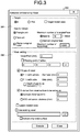
- FIG. 3 is an explanatory diagram for explaining a setting screen. As illustrated in FIG. 3 , a setting screen 200 has setting areas 201 and 202.
- the setting area 201 accepts condition settings such as an extracting method for an exterior portion of the three-dimensional shape. Specifically, the setting area 201 accepts condition settings such as an extracting method for facetizing voxels at a boundary between the first and the second voxels and the non-voxel area or an extracting method for extracting the facets corresponding to the boundary.
- the setting area 202 accepts condition settings for performing voxelization in the first voxelizing unit 10, the area specifying unit 20, or the like. Specifically, the setting area 202 accepts the condition settings such as a pitch of voxelization, a size (details thereof are explained later) of a sphere (or a cube) when performing a process for filling a gap.
- the first voxelizing unit 10 voxelizes (first voxelization) the three-dimensional shape of the product indicated by the three-dimensional shape data of the product under the condition set at S1 (S2).
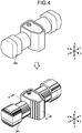
- FIG. 4 is an explanatory diagram for explaining voxelization of a three-dimensional shape.
- the first voxelizing unit 10 voxelizes a three-dimensional shape 300 indicated by the three-dimensional shape data to generate voxels 301 corresponding to the three-dimensional shape 300.
- This voxelization is performed by using, for example, a known algorithm such as setting an area, through which each triangle of the facets included in the three-dimensional shape data passes, to "1 (with a voxel)".
- the area specifying unit 20 specifies an area surrounded by the voxels 301 generated by the first voxelizing unit 10 (S3).
- the second voxelizing unit 30 sets the specified area as voxels to perform voxelization (second voxelization) (S4).
- the second voxelizing unit 30 fills an inner area surrounded by the voxels 301 with the voxels by the processes at S3 and S4.
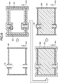
- FIG. 5 is an explanatory diagram for explaining the processes (S3 and S4) of filling the surrounded area. Specifically, FIG. 5 represents a cross section of the voxels 301 in FIG. 4 in an A-A direction.
- the area specifying unit 20 specifies the area surrounded by the voxels 301 from the arrangement of the voxels 301 in the XYZ space. Then, the second voxelizing unit 30 voxelizes the inside of the area surrounded by the voxels 301 and fills the area with the voxels to obtain the voxels 302.
- the area specifying unit 20 may specify an area surrounded by the voxels 301 including an area in which a sphere or a cube of a certain size continuously passes over the voxels 301. Thus, the area specifying unit 20 can fill a gap (a part where voxels are missing) in the voxels 301.
- FIG. 6 is an explanatory diagram for explaining the process of filling a gap.
- the voxels 301 have a gap at a region R1.
- the area specifying unit 20 continuously moves a sphere 303 of the size set with S1 or the like along the voxels 301.
- the area specifying unit 20 obtains an extended area 304 in which the sphere 303 continuously passes over the voxels 301. Because the gap in the voxels 301 at the region R1 is filled with the extended area 304, the area specifying unit 20 can specify the area surrounded by the voxels 301 even if there is a gap in the voxels 301.
- the area specifying unit 20 deletes an area corresponding to a portion extended from the voxels 301 in the outer circumferential direction, from the extended area 304, that is, deletes an area protruding outside the voxels 301. Specifically, the area specifying unit 20 deletes an area that protrudes outside the voxels 301 by the radius of the sphere 303. Accordingly, as illustrated in a region R2 corresponding to the region R1, the extra area protruding outside can be deleted with the gap filled.
- the facetizing unit 40 consults a boundary between the voxels 301 generated by the first voxelizing unit 10 and the voxels 302 generated by the second voxelizing unit 30, and the non-voxel area, that is, rinsezes an exterior portion of the three-dimensional shape indicated by the voxels (S5).
- FIG. 7 and FIG. 8 are explanatory diagrams for explaining facetization.
- the facetizing unit 40 specifies coordinates of XYZ space on the boundary between the voxels 301 and 302 and the non-voxel area.
- the facetizing unit 40 then refers to the facets included in the three-dimensional shape data based on the coordinates of the specified XYZ space to extract a facet corresponding to the coordinates of the specified XYZ space.
- the facetizing unit 40 may also extract the phase/geometric information (BREP) which is a generator of the extracted facets.
- BREP phase/geometric information
- the facetizing unit 40 specifies boundary voxels 302a at the boundary between the voxels 301 and 302 and the non-voxel area. The facetizing unit 40 may then perform facetization by generating facets from the boundary voxels 302a.
- the facetizing unit 40 performs facetization from the boundary voxels 302a.
- surface smoothness smoothing
- the facetizing unit 40 may perform known smoothing processing such as ⁇ smoothing on the facets generated by the Marching Cubes method or the like.
- the output unit 50 outputs the processing result of facetization at S5 (S6). Specifically, the output unit 50 outputs the facets indicating the exterior portion of the three-dimensional shape to the display screen or the like.
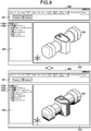
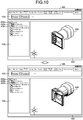
- FIG. 9 and FIG. 10 are explanatory diagrams for explaining a display screen. It is to be noted that FIG. 10 is display examples of the cross sectional shape of the three-dimensional shape 300 and facets 305 in FIG. 9 . As illustrated in FIG. 9 , a display screen 400 includes an operation area 401, a tree display area 402, and a three-dimensional shape display area 403.
- the operation area 401 is an area having various operation buttons, and accepts an operation instruction from the user.
- the tree display area 402 is an area for displaying a display member displayed in the three-dimensional shape display area 403 in a tree form.
- Branches 402b and 402c are set in a tree 402a of the tree display area 402 for each display member displayed in the three-dimensional shape display area 403. By checking on/off checkboxes in the branches 402b and 402c, the user can instruct whether or not to display the display members in the three-dimensional shape display area 403.
- the facets 305 indicating the exterior portion of the three-dimensional shape are displayed in the three-dimensional shape display area 403.
- the user can confirm the exterior portion of the three-dimensional shape with the facets 305.
- the user can switch the display between the three-dimensional shape 300 and the facets 305.
- FIG. 9 and FIG. 10 represent the examples of displaying the facets 305 directly from the three-dimensional shape 300
- the information processing device 1 may display the facets 305 facetized after displaying the display screen for checking voxelization of the three-dimensional shape 300.
- FIG. 11A to FIG. 11C are explanatory diagrams for explaining a display screen when facetization is performed after voxelization.
- the user first performs setting of voxelization by performing operation on the operation area 401 through the display screen 400 which displays the three-dimensional shape 300 in the three-dimensional shape display area 403.
- the user invokes the setting screens 210 and 220, performs condition settings of the voxelization in the first voxelizing unit 10, the area specifying unit 20, and the second voxelizing unit 30, and executes voxelization of the three-dimensional shape 300.
- the voxelization is performed on the three-dimensional shape 300, and, as illustrated in FIG. 11B , the voxels 302 corresponding to the three-dimensional shape 300 are displayed in the three-dimensional shape display area 403. Therefore, the user can confirm the state of the voxels 302 corresponding to the three-dimensional shape 300. The user then invokes a setting screen 230, performs condition settings of facetization in the facetizing unit 40, and executes facetization of the voxels 302.
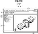
- the facetization is performed on the boundary of the voxels 302, and, as illustrated in FIG. 11C , the facets 305 corresponding to the three-dimensional shape 300 is displayed in the three-dimensional shape display area 403. Therefore, the user can confirm the facets 305 corresponding to the three-dimensional shape 300. In this way, the configuration where the facets 305 are obtained while the user checks each step from the voxelization to the facetization may be adopted.
- the information processing device 1 voxelizes the three-dimensional shape 300, generates the voxels 301 corresponding to the three-dimensional shape 300, and specifies the area surrounded by the voxels 301. Then, the information processing device 1 sets the specified area as the voxels to generate the voxels 302, and infrastructurezes the boundary voxels 302a at the boundary between the voxels 301 and 302 and the non-voxel area. Alternatively, the information processing device 1 extracts facets corresponding to the boundary between the voxels including the voxels 301 and 302 and the non-voxel area, from the facets that express the three-dimensional shape 300.
- the information processing device 1 extracts the exterior of the three-dimensional shape using the voxels 301 and 302 that can simply express the three-dimensional shape, it is possible to suppress the processing load applied to the various computations as compared with the three-dimensional shape data such as the BREP or the facets.
- the components of the illustrated devices are not necessarily physically configured as illustrated.
- the specific mode of distribution and integration of the devices is not limited to the illustrated ones, and all or part of the devices can be configured to be distributed or integrated functionally or physically in arbitrary units according to various loads and usage conditions.
- All or arbitrary part of the various processing functions performed by the information processing device 1 may be executed on a central processing unit (CPU) (or on a microcomputer such as a micro processing unit (MPU) or a micro controller unit (MCU)). In addition, it is needless to say that all or arbitrary part of the various processing functions may be executed on the program analyzed and executed by the CPU (or by the microcomputer such as MPU or MCU) or on the hardware by wired logic.
- the various processing functions performed by the information processing device 1 may be executed in cooperation with a plurality of computers by cloud computing.
- FIG. 12 is a block diagram illustrating an example of a hardware configuration of the information processing device 1 according to the embodiment.
- the information processing device 1 includes a CPU 101 that executes various arithmetic processing, an input device 102 that accepts a data input, a monitor 103, and a speaker 104.
- the information processing device 1 also includes a medium reading device 105 that reads a program or the like from a storage medium, an interface device 106 for connecting to the various devices, and a communication device 107 for communicating with an external device by wired or wireless connection.
- the information processing device 1 further includes random access memory (RAM) 108 that temporarily stores various pieces of information and a hard disk drive 109.
- the units (101 to 109) of the information processing device 1 are connected to a bus 110.
- the hard disk drive 109 stores a program 111 for executing various processing in the first voxelizing unit 10, the area specifying unit 20, the second voxelizing unit 30, the facetizing unit 40, the output unit 50, and the setting unit 60 explained in the embodiment. Moreover, the hard disk drive 109 stores various data 112 (e.g., three-dimensional shape data) referenced by the program 111.
- the input device 102 accepts, for example, an input of operation information from an operator of the information processing device 1.
- the monitor 103 displays, for example, various screens (e.g., the setting screen 200 and the display screen 400) operated by the operator.
- the interface device 106 is connected with, for example, a printing device.
- the communication device 107 is connected to a communication network such as a local area network (LAN), and exchanges various information with an external device via the communication network.
- LAN local area network
- the CPU 101 performs various processing by reading the program 111 stored in the hard disk drive 109, loading the read program into the RAM 108, and executing the program.
- the program 111 does not have to be stored in the hard disk drive 109.
- the program 111 stored in a storage medium readable by the information processing device 1 may be read and executed.
- the storage medium readable by the information processing device 1 corresponds to, for example, a portable recording medium such as a compact disk read only memory (CD-ROM), a digital versatile disk (DVD), and Universal Serial Bus (USB) memory, a semiconductor memory such as a flash memory, and a hard disk drive.
- the configured where the program 111 is stored in a device connected to a public line, the Internet, or LAN, etc. and the information processing device 1 reads the program 111 from any of the devices and executes the program may be adopted.
Landscapes
- Engineering & Computer Science (AREA)
- Physics & Mathematics (AREA)
- Theoretical Computer Science (AREA)
- General Physics & Mathematics (AREA)
- Geometry (AREA)
- Computer Graphics (AREA)
- Software Systems (AREA)
- General Engineering & Computer Science (AREA)
- Evolutionary Computation (AREA)
- Computer Hardware Design (AREA)
- Human Computer Interaction (AREA)
- Image Generation (AREA)
- Processing Or Creating Images (AREA)
- Architecture (AREA)
Abstract
Description
- The embodiments discussed herein are related to a facetization processing method and an information processing device.
- Computer Aided Engineering (CAE) is known as an example of technology to support prior examination of product design, manufacturing, and process design by utilizing computer technology. In the CAE field, by performing simulation based on shape data of three-dimensional shape of a product such as an automobile as a target to be designed, it is possible to verify the assembly process, etc. from the design stage of the target product.
- Patent Literature 1: Japanese Laid-open Patent Publication No.
2006-277672 - However, in the above conventional technology, there is a case in which a processing load increases when extracting an exterior of the product as a target to be designed from the shape data of the three-dimensional shape.
- For example, in manufacturing places of automobiles, etc., there is a case where manufacture of a product to be incorporated in the exterior of a product is consigned to other company. In such a case where the product is consigned to other company, the data indicating the shape of the exterior of the product is extracted and provided. However, in the product such as an automobile, because the size of a surface element indicating the three-dimensional shape of the product is fine and the number of elements is increased, a large processing load is applied to extract the data indicating the shape of the exterior.
- Accordingly, it is an object in one aspect of an embodiment of the invention to provide a facetization processing program, a facet extracting program, a facetization processing method, a facet extracting method, and an information processing device capable of easily extracting an exterior from a three-dimensional shape.
- According to an aspect of an embodiment, a method executed by a computer includes: voxelizing a three-dimensional shape; generating first voxels corresponding to the three-dimensional shape; specifying an area surrounded by the generated first voxels; setting the specified area as voxels to generate second voxels; and facetizing third voxels at a boundary between at least one of the first voxels and a non-voxel area, and the second voxels and the non-voxel area.
-
-
FIG. 1 is a block diagram illustrating an example of a functional configuration of an information processing device according to an embodiment; -
FIG. 2 is a flowchart illustrating an example of an operation of the information processing device according to the embodiment; -
FIG. 3 is an explanatory diagram for explaining a setting screen; -
FIG. 4 is an explanatory diagram for explaining voxelization of a three-dimensional shape; -
FIG. 5 is an explanatory diagram for explaining the process of filling a surrounded area; -
FIG. 6 is an explanatory diagram for explaining the process of filling a gap; -
FIG. 7 is an explanatory diagram for explaining facetization; -
FIG. 8 is an explanatory diagram for explaining facetization; -
FIG. 9 is an explanatory diagram for explaining a display screen; -
FIG. 10 is an explanatory diagram for explaining a display screen; -
FIG. 11A is an explanatory diagram for explaining a display screen when facetization is performed after voxelization; -
FIG. 11B is an explanatory diagram for explaining a display screen when facetization is performed after voxelization; -
FIG. 11C is an explanatory diagram for explaining a display screen when facetization is performed after voxelization; and -
FIG. 12 is a block diagram illustrating an example of a hardware configuration of the information processing device according to the embodiment. - Preferred embodiments of the present invention will be explained with reference to accompanying drawings. In the embodiments, the same reference signs are assigned to components having the same functions and redundant explanation is omitted. The facetization processing program, the facet extracting program, the facetization processing method, the facet extracting method, and the information processing device explained in the following embodiments are only one examples, and are not limited to the embodiments. In addition, the embodiments as follows may be appropriately combined with each other within a range in which no contradiction arises.
-
FIG. 1 is a block diagram illustrating an example of a functional configuration of the information processing device according to the embodiment. As aninformation processing device 1 illustrated inFIG. 1 , for example, a personal computer (PC) can be applied. Theinformation processing device 1 accepts, for example, three-dimensional shape data of a product created by three-dimensional Computer Aided Design (CAD) on a computer. Theinformation processing device 1 then performs processing such as extraction of the exterior of the product based on the accepted three-dimensional shape data, and outputs the processing result to a display or the like. - Here, the three-dimensional shape data is data indicating shapes of components that constitute the product, and Boundary REPresentation (BREP), facets or the like can be applied. The BREP expresses a three-dimensional shape of a product with phase information (Body, Face, Loop, CoEdge, Edge, Vertex, etc.) and geometric information (Base Surface, Base Curve, Base Point, etc.). The facets express a three-dimensional shape of a product with a collection of micro triangles (Body, Face, Triangles, etc.).
- A first voxelizing
unit 10 voxelizes a three-dimensional shape of a product indicated by the three-dimensional shape data of the product to generate voxels (first voxels) corresponding to the three-dimensional shape. - The voxels express a three-dimensional shape with a collection of micro cubes (lattices) in XYZ space. In this way, because the voxels can simply express the three-dimensional shape by presence or absence of micro cubes in the XYZ space, it is possible to suppress the processing load applied to various computations as compared with the three-dimensional shape data such as the BREP and the facets.
- An area specifying unit 20 specifies an area surrounded by the first voxels generated by the first voxelizing
unit 10. A second voxelizingunit 30 sets the area specified by the area specifying unit 20 as voxels and generates the voxels (second voxels). - A facetizing
unit 40 facetizes a boundary between the first voxels generated by the first voxelizingunit 10 and the second voxels generated by the second voxelizingunit 30 and a non-voxel area, that is, facetizes an exterior portion of the three-dimensional shape indicated by the voxels. - Specifically, the facetizing
unit 40 facetizes voxels at a boundary between the first and the second voxels and the non-voxel area. The facetizingunit 40 may facetize an exterior portion of the three-dimensional shape by extracting facets corresponding to the boundary between the first and the second voxels and the non-voxel area from the facets included in the three-dimensional shape data. - An
output unit 50 outputs the result of the processing after the facetization by the facetizingunit 40, that is, the facets indicating the shape of the exterior portion of the three-dimensional shape. As an example, theoutput unit 50 outputs the display data for displaying the exterior portion of the three-dimensional shape based on the facets. As a result, a user can check the shape of the exterior portion of the product indicated by the three-dimensional shape data. - A setting unit 60 is a user interface that accepts various settings from the user. For example, the setting unit 60 performs various settings by displaying a graphical user interface (GUI) on the display and accepting an operation from the user through the GUI. As an example, the setting unit 60 accepts condition settings for extracting the exterior by the voxels in the first voxelizing
unit 10, the area specifying unit 20, the second voxelizingunit 30, and the facetizingunit 40. The setting unit 60 also accepts display settings such as setting for the display data to be output in theoutput unit 50. - Details of the processing in the
information processing device 1 will be explained next.FIG. 2 is flowchart illustrating an example of an operation of theinformation processing device 1 according to the embodiment. - As illustrated in
FIG. 2 , when the process is started, the setting unit 60 sets conditions for extracting the exterior by the voxels based on the operation of the user on the setting screen (S1). -
FIG. 3 is an explanatory diagram for explaining a setting screen. As illustrated inFIG. 3 , asetting screen 200 has settingareas - The
setting area 201 accepts condition settings such as an extracting method for an exterior portion of the three-dimensional shape. Specifically, thesetting area 201 accepts condition settings such as an extracting method for facetizing voxels at a boundary between the first and the second voxels and the non-voxel area or an extracting method for extracting the facets corresponding to the boundary. - The
setting area 202 accepts condition settings for performing voxelization in thefirst voxelizing unit 10, the area specifying unit 20, or the like. Specifically, thesetting area 202 accepts the condition settings such as a pitch of voxelization, a size (details thereof are explained later) of a sphere (or a cube) when performing a process for filling a gap. - Following S1, the
first voxelizing unit 10 voxelizes (first voxelization) the three-dimensional shape of the product indicated by the three-dimensional shape data of the product under the condition set at S1 (S2). -
FIG. 4 is an explanatory diagram for explaining voxelization of a three-dimensional shape. As illustrated inFIG. 4 , thefirst voxelizing unit 10 voxelizes a three-dimensional shape 300 indicated by the three-dimensional shape data to generatevoxels 301 corresponding to the three-dimensional shape 300. This voxelization is performed by using, for example, a known algorithm such as setting an area, through which each triangle of the facets included in the three-dimensional shape data passes, to "1 (with a voxel)". - Then, the area specifying unit 20 specifies an area surrounded by the
voxels 301 generated by the first voxelizing unit 10 (S3). Thesecond voxelizing unit 30 sets the specified area as voxels to perform voxelization (second voxelization) (S4). Thesecond voxelizing unit 30 fills an inner area surrounded by thevoxels 301 with the voxels by the processes at S3 and S4. -
FIG. 5 is an explanatory diagram for explaining the processes (S3 and S4) of filling the surrounded area. Specifically,FIG. 5 represents a cross section of thevoxels 301 inFIG. 4 in an A-A direction. - As illustrated in
FIG. 5 , the area specifying unit 20 specifies the area surrounded by thevoxels 301 from the arrangement of thevoxels 301 in the XYZ space. Then, thesecond voxelizing unit 30 voxelizes the inside of the area surrounded by thevoxels 301 and fills the area with the voxels to obtain thevoxels 302. - The area specifying unit 20 may specify an area surrounded by the
voxels 301 including an area in which a sphere or a cube of a certain size continuously passes over thevoxels 301. Thus, the area specifying unit 20 can fill a gap (a part where voxels are missing) in thevoxels 301. -
FIG. 6 is an explanatory diagram for explaining the process of filling a gap. As illustrated inFIG. 6 , it is assumed that thevoxels 301 have a gap at a region R1. The area specifying unit 20 continuously moves asphere 303 of the size set with S1 or the like along thevoxels 301. As a result, the area specifying unit 20 obtains anextended area 304 in which thesphere 303 continuously passes over thevoxels 301. Because the gap in thevoxels 301 at the region R1 is filled with theextended area 304, the area specifying unit 20 can specify the area surrounded by thevoxels 301 even if there is a gap in thevoxels 301. - In addition, the area specifying unit 20 deletes an area corresponding to a portion extended from the
voxels 301 in the outer circumferential direction, from theextended area 304, that is, deletes an area protruding outside thevoxels 301. Specifically, the area specifying unit 20 deletes an area that protrudes outside thevoxels 301 by the radius of thesphere 303. Accordingly, as illustrated in a region R2 corresponding to the region R1, the extra area protruding outside can be deleted with the gap filled. - Following S4, the
facetizing unit 40 facetizes a boundary between thevoxels 301 generated by thefirst voxelizing unit 10 and thevoxels 302 generated by thesecond voxelizing unit 30, and the non-voxel area, that is, facetizes an exterior portion of the three-dimensional shape indicated by the voxels (S5). -
FIG. 7 andFIG. 8 are explanatory diagrams for explaining facetization. As illustrated inFIG. 7 , thefacetizing unit 40 specifies coordinates of XYZ space on the boundary between thevoxels facetizing unit 40 then refers to the facets included in the three-dimensional shape data based on the coordinates of the specified XYZ space to extract a facet corresponding to the coordinates of the specified XYZ space. Moreover, when the three-dimensional shape data has the phase/geometric information (BREP), thefacetizing unit 40 may also extract the phase/geometric information (BREP) which is a generator of the extracted facets. - As illustrated in
FIG. 8 , thefacetizing unit 40 specifiesboundary voxels 302a at the boundary between thevoxels facetizing unit 40 may then perform facetization by generating facets from theboundary voxels 302a. - As an example, by using a known method such as Marching Cubes, the
facetizing unit 40 performs facetization from theboundary voxels 302a. However, surface smoothness (smoothing) may be lost in the case of facetization based on theboundary voxels 302a. Therefore, thefacetizing unit 40 may perform known smoothing processing such as λµ smoothing on the facets generated by the Marching Cubes method or the like. - Following S5, the
output unit 50 outputs the processing result of facetization at S5 (S6). Specifically, theoutput unit 50 outputs the facets indicating the exterior portion of the three-dimensional shape to the display screen or the like. -
FIG. 9 andFIG. 10 are explanatory diagrams for explaining a display screen. It is to be noted thatFIG. 10 is display examples of the cross sectional shape of the three-dimensional shape 300 andfacets 305 inFIG. 9 . As illustrated inFIG. 9 , adisplay screen 400 includes anoperation area 401, atree display area 402, and a three-dimensionalshape display area 403. - The
operation area 401 is an area having various operation buttons, and accepts an operation instruction from the user. Thetree display area 402 is an area for displaying a display member displayed in the three-dimensionalshape display area 403 in a tree form.Branches tree 402a of thetree display area 402 for each display member displayed in the three-dimensionalshape display area 403. By checking on/off checkboxes in thebranches shape display area 403. - At S6, the
facets 305 indicating the exterior portion of the three-dimensional shape are displayed in the three-dimensionalshape display area 403. As a result, the user can confirm the exterior portion of the three-dimensional shape with thefacets 305. Moreover, by checking on/off checkboxes in thebranches tree 402a in thetree display area 402, the user can switch the display between the three-dimensional shape 300 and thefacets 305. - Specifically, as illustrated in
FIG. 10 , by checking on the checkbox of thebranch 402c and checking off the checkbox of thebranch 402b, it is possible to delete the three-dimensional shape 300 and to display thefacets 305. - Although
FIG. 9 andFIG. 10 represent the examples of displaying thefacets 305 directly from the three-dimensional shape 300, theinformation processing device 1 may display thefacets 305 facetized after displaying the display screen for checking voxelization of the three-dimensional shape 300. -
FIG. 11A to FIG. 11C are explanatory diagrams for explaining a display screen when facetization is performed after voxelization. As illustrated inFIG. 11A , the user first performs setting of voxelization by performing operation on theoperation area 401 through thedisplay screen 400 which displays the three-dimensional shape 300 in the three-dimensionalshape display area 403. Specifically, the user invokes the setting screens 210 and 220, performs condition settings of the voxelization in thefirst voxelizing unit 10, the area specifying unit 20, and thesecond voxelizing unit 30, and executes voxelization of the three-dimensional shape 300. - Thus, the voxelization is performed on the three-
dimensional shape 300, and, as illustrated inFIG. 11B , thevoxels 302 corresponding to the three-dimensional shape 300 are displayed in the three-dimensionalshape display area 403. Therefore, the user can confirm the state of thevoxels 302 corresponding to the three-dimensional shape 300. The user then invokes asetting screen 230, performs condition settings of facetization in thefacetizing unit 40, and executes facetization of thevoxels 302. - Accordingly, the facetization is performed on the boundary of the
voxels 302, and, as illustrated inFIG. 11C , thefacets 305 corresponding to the three-dimensional shape 300 is displayed in the three-dimensionalshape display area 403. Therefore, the user can confirm thefacets 305 corresponding to the three-dimensional shape 300. In this way, the configuration where thefacets 305 are obtained while the user checks each step from the voxelization to the facetization may be adopted. - As explained above, the
information processing device 1 voxelizes the three-dimensional shape 300, generates thevoxels 301 corresponding to the three-dimensional shape 300, and specifies the area surrounded by thevoxels 301. Then, theinformation processing device 1 sets the specified area as the voxels to generate thevoxels 302, and facetizes theboundary voxels 302a at the boundary between thevoxels information processing device 1 extracts facets corresponding to the boundary between the voxels including thevoxels dimensional shape 300. In this way, because theinformation processing device 1 extracts the exterior of the three-dimensional shape using thevoxels - In addition, the components of the illustrated devices are not necessarily physically configured as illustrated. In other words, the specific mode of distribution and integration of the devices is not limited to the illustrated ones, and all or part of the devices can be configured to be distributed or integrated functionally or physically in arbitrary units according to various loads and usage conditions.
- All or arbitrary part of the various processing functions performed by the
information processing device 1 may be executed on a central processing unit (CPU) (or on a microcomputer such as a micro processing unit (MPU) or a micro controller unit (MCU)). In addition, it is needless to say that all or arbitrary part of the various processing functions may be executed on the program analyzed and executed by the CPU (or by the microcomputer such as MPU or MCU) or on the hardware by wired logic. The various processing functions performed by theinformation processing device 1 may be executed in cooperation with a plurality of computers by cloud computing. - Incidentally, the various types of processing explained in the embodiment can be implemented by a computer executing a prepared program. Therefore, an example of the computer (hardware) that executes the program having the same functions as these of the embodiment will be explained below.
FIG. 12 is a block diagram illustrating an example of a hardware configuration of theinformation processing device 1 according to the embodiment. - As illustrated in
FIG. 12 , theinformation processing device 1 includes aCPU 101 that executes various arithmetic processing, aninput device 102 that accepts a data input, amonitor 103, and aspeaker 104. Theinformation processing device 1 also includes amedium reading device 105 that reads a program or the like from a storage medium, aninterface device 106 for connecting to the various devices, and acommunication device 107 for communicating with an external device by wired or wireless connection. Theinformation processing device 1 further includes random access memory (RAM) 108 that temporarily stores various pieces of information and ahard disk drive 109. The units (101 to 109) of theinformation processing device 1 are connected to abus 110. - The
hard disk drive 109 stores aprogram 111 for executing various processing in thefirst voxelizing unit 10, the area specifying unit 20, thesecond voxelizing unit 30, thefacetizing unit 40, theoutput unit 50, and the setting unit 60 explained in the embodiment. Moreover, thehard disk drive 109 stores various data 112 (e.g., three-dimensional shape data) referenced by theprogram 111. Theinput device 102 accepts, for example, an input of operation information from an operator of theinformation processing device 1. Themonitor 103 displays, for example, various screens (e.g., thesetting screen 200 and the display screen 400) operated by the operator. Theinterface device 106 is connected with, for example, a printing device. Thecommunication device 107 is connected to a communication network such as a local area network (LAN), and exchanges various information with an external device via the communication network. - The
CPU 101 performs various processing by reading theprogram 111 stored in thehard disk drive 109, loading the read program into theRAM 108, and executing the program. Theprogram 111 does not have to be stored in thehard disk drive 109. For example, theprogram 111 stored in a storage medium readable by theinformation processing device 1 may be read and executed. The storage medium readable by theinformation processing device 1 corresponds to, for example, a portable recording medium such as a compact disk read only memory (CD-ROM), a digital versatile disk (DVD), and Universal Serial Bus (USB) memory, a semiconductor memory such as a flash memory, and a hard disk drive. The configured where theprogram 111 is stored in a device connected to a public line, the Internet, or LAN, etc. and theinformation processing device 1 reads theprogram 111 from any of the devices and executes the program may be adopted. - According to an embodiment, it is possible to easily extract the exterior from the three-dimensional shape.
Claims (9)
- A method executed by a computer, the method comprising:voxelizing a three-dimensional shape;generating first voxels corresponding to the three-dimensional shape;specifying an area surrounded by the generated first voxels;setting the specified area as voxels to generate second voxels; andfacetizing third voxels at a boundary between at least one of the first voxels and a non-voxel area, and the second voxels and the non-voxel area.
- The method according to claim 1, wherein the specifying the area includes specifying the area including an area in which a sphere or a cube of a certain size continuously passes over the first voxels.
- The method according to claim 2, wherein the specifying the area includes deleting an area corresponding to a portion extended from the first voxels in an outer circumferential direction, from the area in which the sphere or the cube of the certain size passes.
- A program which, when executed by the computer, causes the computer to carry out the method according to any one of claims 1 to 3.
- A storage medium storing the program of claim 4.
- An information processing device (1) comprising:a first voxelizing unit (10) configured to voxelize a three-dimensional shape and to generate first voxels corresponding to the three-dimensional shape;an area specifying unit (20) configured to specify an area surrounded by the generated first voxels;a second voxelizing unit (30) configured to set the specified area as voxels to generate second voxels; anda facetizing unit (40) configured to extract facets corresponding to a boundary between voxels including the first and the second voxels and a non-voxel area from facets that express the three-dimensional shape.
- The information processing device according to claim 6, wherein the area specifying unit (20) specifies the area including an area in which a sphere or a cube of a certain size continuously passes over the first voxels.
- The information processing device according to claim 7, wherein the area specifying unit (20) deletes an area corresponding to a portion extended from the first voxels in an outer circumferential direction, from the area in which the sphere or the cube of the certain size passes.
- The information processing device according to claim 6, wherein the facetizing unit (40) extracts also phase/geometric information included in the three-dimensional shape.
Applications Claiming Priority (1)
| Application Number | Priority Date | Filing Date | Title |
|---|---|---|---|
| JP2016136435A JP6790526B2 (en) | 2016-07-08 | 2016-07-08 | Faceted processing program, facet extraction program, faceted processing method, facet extraction method and information processing device |
Publications (1)
| Publication Number | Publication Date |
|---|---|
| EP3282425A1 true EP3282425A1 (en) | 2018-02-14 |
Family
ID=59239840
Family Applications (1)
| Application Number | Title | Priority Date | Filing Date |
|---|---|---|---|
| EP17178061.2A Withdrawn EP3282425A1 (en) | 2016-07-08 | 2017-06-27 | Facetization processing method and information processing device |
Country Status (5)
| Country | Link |
|---|---|
| US (1) | US10366179B2 (en) |
| EP (1) | EP3282425A1 (en) |
| JP (1) | JP6790526B2 (en) |
| KR (1) | KR101923316B1 (en) |
| CN (1) | CN107590299B (en) |
Families Citing this family (1)
| Publication number | Priority date | Publication date | Assignee | Title |
|---|---|---|---|---|
| JP7439547B2 (en) * | 2020-01-31 | 2024-02-28 | 富士フイルムビジネスイノベーション株式会社 | Information processing device and information processing program |
Citations (4)
| Publication number | Priority date | Publication date | Assignee | Title |
|---|---|---|---|---|
| US6545676B1 (en) * | 1999-05-24 | 2003-04-08 | Parametric Technology Corporation | Method and system for creating a tessellated approximation of an outer envelope of a complex model |
| DE10360150A1 (en) * | 2003-12-20 | 2005-07-14 | Daimlerchrysler Ag | Method for generating an envelope |
| JP2006277672A (en) | 2005-03-30 | 2006-10-12 | Fujitsu Ltd | 3D model processing method |
| US20140146047A1 (en) * | 2012-01-09 | 2014-05-29 | Wen-Jun Wu | System and method for generating an outer layer representation of an object |
Family Cites Families (15)
| Publication number | Priority date | Publication date | Assignee | Title |
|---|---|---|---|---|
| JP3265879B2 (en) * | 1994-11-25 | 2002-03-18 | 日産自動車株式会社 | 3D orthogonal grid data generator |
| EP1519318A4 (en) * | 2002-06-28 | 2008-11-19 | Fujitsu Ltd | PROGRAM AND METHOD FOR COMPARING THREE-DIMENSIONAL IMAGE AND APPARATUS THEREFOR |
| US7859530B2 (en) * | 2003-04-30 | 2010-12-28 | Pixar | Subsurface rendering methods and apparatus |
| US20050151734A1 (en) * | 2004-01-14 | 2005-07-14 | Gubkin Andrew A. | Method and apparatus for rendering, storing and editing voxel objects |
| US7576737B2 (en) * | 2004-09-24 | 2009-08-18 | Konica Minolta Medical & Graphic, Inc. | Image processing device and program |
| JP4764663B2 (en) * | 2005-05-30 | 2011-09-07 | 富士通株式会社 | Method for automatically recognizing geometric shape in virtual three-dimensional coordinate space, three-dimensional CAD system and three-dimensional CAD program |
| GB201003065D0 (en) * | 2010-02-23 | 2010-04-07 | Simpleware Ltd | Image processing method and method of three-dimensional printing incorporating the same |
| JP5022508B1 (en) | 2011-06-02 | 2012-09-12 | 三菱重工業株式会社 | Shape measurement method |
| CN103236079B (en) * | 2013-04-19 | 2015-07-22 | 浙江理工大学 | Improved three-dimensional model voxelization-based inner sphere construction method |
| GB2515510B (en) * | 2013-06-25 | 2019-12-25 | Synopsys Inc | Image processing method |
| JP6087242B2 (en) | 2013-08-08 | 2017-03-01 | 三菱電機株式会社 | Model conversion method and model conversion apparatus |
| US9811714B2 (en) * | 2013-08-28 | 2017-11-07 | Autodesk, Inc. | Building datum extraction from laser scanning data |
| CN103617603B (en) * | 2013-12-06 | 2016-02-24 | 南京大学 | A kind of self-repairing method of 3-dimensional digital geometric mesh model structure |
| US10062203B2 (en) * | 2015-12-18 | 2018-08-28 | Autodesk, Inc. | Voxelization of mesh representations |
| CN105719349B (en) * | 2016-01-19 | 2018-07-31 | 中国科学院自动化研究所 | Based on the tetrahedral grid method and system for maximizing the sampling of Poisson disk |
-
2016
- 2016-07-08 JP JP2016136435A patent/JP6790526B2/en active Active
-
2017
- 2017-06-23 US US15/631,494 patent/US10366179B2/en active Active
- 2017-06-27 EP EP17178061.2A patent/EP3282425A1/en not_active Withdrawn
- 2017-06-28 CN CN201710508970.6A patent/CN107590299B/en active Active
- 2017-06-29 KR KR1020170082431A patent/KR101923316B1/en active Active
Patent Citations (4)
| Publication number | Priority date | Publication date | Assignee | Title |
|---|---|---|---|---|
| US6545676B1 (en) * | 1999-05-24 | 2003-04-08 | Parametric Technology Corporation | Method and system for creating a tessellated approximation of an outer envelope of a complex model |
| DE10360150A1 (en) * | 2003-12-20 | 2005-07-14 | Daimlerchrysler Ag | Method for generating an envelope |
| JP2006277672A (en) | 2005-03-30 | 2006-10-12 | Fujitsu Ltd | 3D model processing method |
| US20140146047A1 (en) * | 2012-01-09 | 2014-05-29 | Wen-Jun Wu | System and method for generating an outer layer representation of an object |
Non-Patent Citations (1)
| Title |
|---|
| F.S. NOORUDDIN ET AL: "Simplification and repair of polygonal models using volumetric techniques", IEEE TRANSACTIONS ON VISUALIZATION AND COMPUTER GRAPHICS, vol. 9, no. 2, April 2003 (2003-04-01), pages 191 - 205, XP055069494, ISSN: 1077-2626, DOI: 10.1109/TVCG.2003.1196006 * |
Also Published As
| Publication number | Publication date |
|---|---|
| KR101923316B1 (en) | 2018-11-28 |
| CN107590299B (en) | 2021-06-11 |
| US20180011946A1 (en) | 2018-01-11 |
| US10366179B2 (en) | 2019-07-30 |
| JP6790526B2 (en) | 2020-11-25 |
| KR20180006305A (en) | 2018-01-17 |
| JP2018005862A (en) | 2018-01-11 |
| CN107590299A (en) | 2018-01-16 |
Similar Documents
| Publication | Publication Date | Title |
|---|---|---|
| US10339266B2 (en) | Mechanisms for constructing spline surfaces to provide inter-surface continuity | |
| US11520944B2 (en) | System and method for modeling of parts with lattice structures | |
| US10534893B2 (en) | Execution of sequential update | |
| US20230114354A1 (en) | Designing a modeled object | |
| US10943037B2 (en) | Generating a CAD model from a finite element mesh | |
| EP3179389B1 (en) | Detecting cut-outs | |
| US10521516B2 (en) | Criterion for sequential update | |
| EP3293648A1 (en) | Representation of a skeleton of a mechanical part | |
| US10297069B2 (en) | Computer-readable recording medium, shortest path determining method, and information processing device | |
| US10096156B2 (en) | Computer-readable recording medium, voxelization method, and information processing device for automatic voxelization of 3D shapes | |
| EP3282425A1 (en) | Facetization processing method and information processing device | |
| JP2021033769A (en) | 3D shape data editing device and 3D shape data editing program | |
| JP6942007B2 (en) | Image processing equipment and programs | |
| US10223824B2 (en) | Information processing apparatus, simulator result display method, and computer-readable recording medium | |
| US10089795B2 (en) | Method and apparatus for determining arrangement position of leader line | |
| KR102818814B1 (en) | Interactive image segmentation method and apparatus thereof | |
| KR102156336B1 (en) | Method for reconstructing three-dimensional shape | |
| US9785636B2 (en) | Document management method and design document management apparatus | |
| WO2017204196A1 (en) | Three-dimensional shape data creation device and three-dimensional shape data creation assist method | |
| KR101689132B1 (en) | Apparatus and method for rendering three dimensional image in electronic device |
Legal Events
| Date | Code | Title | Description |
|---|---|---|---|
| PUAI | Public reference made under article 153(3) epc to a published international application that has entered the european phase |
Free format text: ORIGINAL CODE: 0009012 |
|
| AK | Designated contracting states |
Kind code of ref document: A1 Designated state(s): AL AT BE BG CH CY CZ DE DK EE ES FI FR GB GR HR HU IE IS IT LI LT LU LV MC MK MT NL NO PL PT RO RS SE SI SK SM TR |
|
| AX | Request for extension of the european patent |
Extension state: BA ME |
|
| 17P | Request for examination filed |
Effective date: 20180606 |
|
| RBV | Designated contracting states (corrected) |
Designated state(s): AL AT BE BG CH CY CZ DE DK EE ES FI FR GB GR HR HU IE IS IT LI LT LU LV MC MK MT NL NO PL PT RO RS SE SI SK SM TR |
|
| 17Q | First examination report despatched |
Effective date: 20190528 |
|
| STAA | Information on the status of an ep patent application or granted ep patent |
Free format text: STATUS: THE APPLICATION HAS BEEN WITHDRAWN |
|
| 18W | Application withdrawn |
Effective date: 20190927 |