EP3282421A1 - Systems and methods for identifying body joint locations based on sensor data analysis - Google Patents
Systems and methods for identifying body joint locations based on sensor data analysis Download PDFInfo
- Publication number
- EP3282421A1 EP3282421A1 EP17161945.5A EP17161945A EP3282421A1 EP 3282421 A1 EP3282421 A1 EP 3282421A1 EP 17161945 A EP17161945 A EP 17161945A EP 3282421 A1 EP3282421 A1 EP 3282421A1
- Authority
- EP
- European Patent Office
- Prior art keywords
- joint locations
- body joint
- data
- body segment
- locations
- Prior art date
- Legal status (The legal status is an assumption and is not a legal conclusion. Google has not performed a legal analysis and makes no representation as to the accuracy of the status listed.)
- Granted
Links
Images


Classifications
-
- G—PHYSICS
- G06—COMPUTING OR CALCULATING; COUNTING
- G06T—IMAGE DATA PROCESSING OR GENERATION, IN GENERAL
- G06T7/00—Image analysis
- G06T7/0002—Inspection of images, e.g. flaw detection
- G06T7/0012—Biomedical image inspection
-
- G—PHYSICS
- G06—COMPUTING OR CALCULATING; COUNTING
- G06V—IMAGE OR VIDEO RECOGNITION OR UNDERSTANDING
- G06V40/00—Recognition of biometric, human-related or animal-related patterns in image or video data
- G06V40/20—Movements or behaviour, e.g. gesture recognition
- G06V40/28—Recognition of hand or arm movements, e.g. recognition of deaf sign language
-
- A—HUMAN NECESSITIES
- A61—MEDICAL OR VETERINARY SCIENCE; HYGIENE
- A61B—DIAGNOSIS; SURGERY; IDENTIFICATION
- A61B5/00—Measuring for diagnostic purposes; Identification of persons
- A61B5/103—Measuring devices for testing the shape, pattern, colour, size or movement of the body or parts thereof, for diagnostic purposes
- A61B5/11—Measuring movement of the entire body or parts thereof, e.g. head or hand tremor or mobility of a limb
- A61B5/1121—Determining geometric values, e.g. centre of rotation or angular range of movement
-
- A—HUMAN NECESSITIES
- A61—MEDICAL OR VETERINARY SCIENCE; HYGIENE
- A61B—DIAGNOSIS; SURGERY; IDENTIFICATION
- A61B5/00—Measuring for diagnostic purposes; Identification of persons
- A61B5/103—Measuring devices for testing the shape, pattern, colour, size or movement of the body or parts thereof, for diagnostic purposes
- A61B5/11—Measuring movement of the entire body or parts thereof, e.g. head or hand tremor or mobility of a limb
- A61B5/1126—Measuring movement of the entire body or parts thereof, e.g. head or hand tremor or mobility of a limb using a particular sensing technique
- A61B5/1128—Measuring movement of the entire body or parts thereof, e.g. head or hand tremor or mobility of a limb using a particular sensing technique using image analysis
-
- A—HUMAN NECESSITIES
- A61—MEDICAL OR VETERINARY SCIENCE; HYGIENE
- A61B—DIAGNOSIS; SURGERY; IDENTIFICATION
- A61B5/00—Measuring for diagnostic purposes; Identification of persons
- A61B5/72—Signal processing specially adapted for physiological signals or for diagnostic purposes
- A61B5/7271—Specific aspects of physiological measurement analysis
-
- G—PHYSICS
- G06—COMPUTING OR CALCULATING; COUNTING
- G06T—IMAGE DATA PROCESSING OR GENERATION, IN GENERAL
- G06T7/00—Image analysis
- G06T7/10—Segmentation; Edge detection
- G06T7/143—Segmentation; Edge detection involving probabilistic approaches, e.g. Markov random field [MRF] modelling
-
- G—PHYSICS
- G06—COMPUTING OR CALCULATING; COUNTING
- G06T—IMAGE DATA PROCESSING OR GENERATION, IN GENERAL
- G06T7/00—Image analysis
- G06T7/50—Depth or shape recovery
- G06T7/55—Depth or shape recovery from multiple images
- G06T7/593—Depth or shape recovery from multiple images from stereo images
-
- G—PHYSICS
- G06—COMPUTING OR CALCULATING; COUNTING
- G06T—IMAGE DATA PROCESSING OR GENERATION, IN GENERAL
- G06T7/00—Image analysis
- G06T7/70—Determining position or orientation of objects or cameras
-
- G—PHYSICS
- G06—COMPUTING OR CALCULATING; COUNTING
- G06T—IMAGE DATA PROCESSING OR GENERATION, IN GENERAL
- G06T7/00—Image analysis
- G06T7/70—Determining position or orientation of objects or cameras
- G06T7/73—Determining position or orientation of objects or cameras using feature-based methods
- G06T7/75—Determining position or orientation of objects or cameras using feature-based methods involving models
-
- G—PHYSICS
- G06—COMPUTING OR CALCULATING; COUNTING
- G06T—IMAGE DATA PROCESSING OR GENERATION, IN GENERAL
- G06T2207/00—Indexing scheme for image analysis or image enhancement
- G06T2207/10—Image acquisition modality
- G06T2207/10016—Video; Image sequence
-
- G—PHYSICS
- G06—COMPUTING OR CALCULATING; COUNTING
- G06T—IMAGE DATA PROCESSING OR GENERATION, IN GENERAL
- G06T2207/00—Indexing scheme for image analysis or image enhancement
- G06T2207/10—Image acquisition modality
- G06T2207/10024—Color image
-
- G—PHYSICS
- G06—COMPUTING OR CALCULATING; COUNTING
- G06T—IMAGE DATA PROCESSING OR GENERATION, IN GENERAL
- G06T2207/00—Indexing scheme for image analysis or image enhancement
- G06T2207/10—Image acquisition modality
- G06T2207/10028—Range image; Depth image; 3D point clouds
-
- G—PHYSICS
- G06—COMPUTING OR CALCULATING; COUNTING
- G06T—IMAGE DATA PROCESSING OR GENERATION, IN GENERAL
- G06T2207/00—Indexing scheme for image analysis or image enhancement
- G06T2207/30—Subject of image; Context of image processing
- G06T2207/30004—Biomedical image processing
- G06T2207/30008—Bone
-
- G—PHYSICS
- G06—COMPUTING OR CALCULATING; COUNTING
- G06T—IMAGE DATA PROCESSING OR GENERATION, IN GENERAL
- G06T2207/00—Indexing scheme for image analysis or image enhancement
- G06T2207/30—Subject of image; Context of image processing
- G06T2207/30241—Trajectory
Definitions
- the disclosure herein generally relate to sensor data analysis, and, more particularly, to systems and methods for identifying body joint locations based on sensor data analysis.
- Joint motion analysis is an important aspect of health monitoring / rehabilitation of patients suffering from neurological disorders, post stroke patients, and elderly subjects.
- Joint movement data capture is traditionally done using clinical devices such as Vicon, which is marker-based and extremely expensive and ill-suited for prolonged rehabilitation therapy.
- Kinect® is a marker-less motion capture device that is being used for its low cost, portability and ease of cost when compared to its expensive counterpart.
- the accuracy of Kinect® as an alternative to Marker-based systems has been widely studied and there are extensive reports on its validity and reliability in comparison to Vicon. However, the reports indicate a lower accuracy of the human body joint information provided by Kinect® skeletal data.
- the skeleton data provided by Kinect® requires further optimization to improve its accuracy and allow effective and reliable assessment.
- a hardware processor implemented method for identifying body joint locations comprises obtaining, by one or more hardware processors, input data comprising skeletal data, depth data, and red, green, and blue (RGB) data pertaining to at least one user at one or more time stamps, wherein the one or more input data comprises three dimensional (3D) coordinates pertaining to one or more skeleton joints.
- input data comprising skeletal data, depth data, and red, green, and blue (RGB) data pertaining to at least one user at one or more time stamps
- RGB red, green, and blue
- the method further comprises estimating, using the one or more input data, by the one or more hardware processors, one or more body joint locations and a body segment length of one or more body segments connected to corresponding skeleton joints to obtain (i) an estimate of one or more body joint locations and (ii) an estimate of one or more body segment lengths.
- the one or more body segment lengths are based on a Euclidean distance between adjacent skeleton joints.
- One or more probable correct body joint locations are identified in a bounded neighborhood around the one or more body joint locations that are previously obtained in a previous frame, wherein the one or more probable correct body joint locations are iteratively identified based on the depth data and the RGB data.
- a search region is defined for identifying the one or more probable correct body joint locations using a radius equivalent to a displacement of a corresponding skeleton joint in a single frame.
- the method further comprises performing, by the one or more hardware processors, a comparison of (i) a body segment length associated with each of the one or more probable correct body joint locations and (ii) a reference length.
- the reference length is derived based on the estimate of the one or more body segment lengths.
- a subset of the one or more probable correct body joint locations are identified as one or more candidate body joint locations based on the comparison.
- the subset of the one or more probable correct body joint locations are identified as one or more candidate body joint locations based on the comparison resulting in a minimal body segment length variation.
- a physical orientation of each body segment pertaining to each of the one or more candidate body joint locations is determined by segmenting one or more 3D coordinates of each body segment based on the depth data and performing an analysis on each segmented 3D coordinate.
- a (corrected) body joint location is identified from the one or more candidate body joint locations based on a minimal deviation in direction from the physical orientation of a corresponding body segment along with a feature descriptor of the RGB data and the depth data, wherein the minimal deviation is based on the depth data, and, wherein the minimal deviation is based on one or more actions performed by the user.
- a system for identifying a body joint location comprises a memory storing instructions, one or more communication interfaces, and one or more hardware processors coupled to the memory using the one or more communication interfaces, wherein the one or more hardware processors are configured by the instructions to: obtain one or more input data comprising skeletal data, depth data and red, green, and blue (RGB) data pertaining to at least one user at one or more time stamps, wherein the one or more input data comprising three dimensional (3D) coordinates pertaining to one or more skeleton joints.
- the skeletal data, depth data and red, green, and blue (RGB) data are captured by a sensor (e.g., Kinect® sensor).
- the one or more hardware processors are further configured by the instructions to estimate, using the one or more input data, one or more body joint locations and a body segment length of one or more body segments connecting to corresponding skeleton joints to obtain (i) an estimate of one or more body joint locations and (ii) an estimate of one or more body segment lengths.
- one or more body segment lengths are based on a Euclidean distance between adjacent skeleton joints.
- the system is further configured to identify one or more probable correct body joint locations in a bounded neighborhood around the one or more body joint locations that are previously obtained from a previous frame, wherein the one or more probable correct body joint locations are iteratively identified based on the depth data and the RGB data.
- a search region is defined to identify the one or more probable correct body joint locations based on a radius equivalent to a displacement of a corresponding skeleton joint in a single frame.
- the system further performs a comparison of (i) a body segment length associated with each of the one or more probable correct body joint locations and (ii) a reference length.
- the reference length is derived based on the estimate of the one or more body segment lengths.
- the system further identifies a subset of the one or more probable correct body joint locations as one or more candidate body joint locations based on the comparison.
- the subset of the one or more probable correct body joint locations are identified as one or more candidate body joint locations based on the comparison resulting in a minimal body segment length variation.
- probable correct body joint locations having a minimal body segment length variation with respect to the reference length are identified as one or more candidate body joint locations.
- the system is further configured to determine a physical orientation of each body segment pertaining to each of the one or more candidate body joint locations by segmenting one or more 3D coordinates of each body segment based on the depth data and performing an analysis on each segmented 3D coordinate.
- the system is further configured to identify, from the one or more candidate body joint locations, a (corrected) body joint location based on a minimal deviation in direction from the physical orientation of a corresponding body segment along with a feature descriptor of the RGB data and the depth data, wherein the minimal deviation is based on the depth data, and wherein the minimal deviation is based on one or more actions performed by the user.
- a body joint location having a minimal deviation in direction from the physical orientation of a corresponding body segment is identified as a corrected joint body location along with a feature descriptor of the RGB data and the depth data.
- one or more non-transitory machine readable information storage mediums comprising one or more instructions.
- the one or more instructions which when executed by one or more hardware processors causes obtaining input data comprising skeletal data, depth data and red, green, and blue (RGB) data pertaining to at least one user at one or more time stamps, wherein the input data comprises three dimensional (3D) coordinates pertaining to one or more skeleton joints.
- the one or more instructions which when executed by one or more hardware processors further causes estimating, using the one or more input data, one or more body joint locations and a body segment length of one or more body segments connecting to corresponding skeleton joints to obtain (i) an estimate of one or more body joint locations and (ii) an estimate of one or more body segment lengths.
- the one or more body segment lengths are based on a Euclidean distance between adjacent skeleton joints.
- the one or more instructions which when executed by one or more hardware processors causes identifying one or more probable correct body joint locations in a bounded neighborhood around the one or more body joint locations that are previously obtained, wherein the one or more probable correct body joint locations are iteratively identified based on the depth data and the RGB data.
- a search region is defined for identifying the one or more probable correct body joint locations using a radius equivalent to a displacement of a corresponding skeleton joint.
- the one or more instructions which when executed by one or more hardware processors further causes performing a comparison of (i) a body segment length associated with each of the one or more probable correct body joint locations and (ii) a reference length.
- the reference length is derived based on the estimate of the one or more estimated body segment lengths.
- the one or more instructions which when executed by one or more hardware processors further causes identifying a subset of the one or more probable correct body joint locations as one or more candidate body joint locations based on the comparison.
- identifying a subset of the one or more probable correct body joint locations as one or more candidate body joint locations is based on the comparison resulting in a minimal body segment length variation.
- the one or more instructions which when executed by one or more hardware processors further causes determining a physical orientation of each body segment pertaining to each of the one or more candidate body joint locations by segmenting one or more 3D coordinates of each body segment based on the depth data and performing an analysis on each segmented 3D coordinate.
- the one or more instructions which when executed by one or more hardware processors further causes identifying, from the one or more candidate body joint locations, a (corrected) body joint location based on a minimal deviation in direction from the physical orientation of a corresponding body segment along with a feature descriptor of the RGB data and the depth data, wherein said minimal deviation is based on the depth data, and, wherein the minimal deviation is based on one or more actions performed by the user.
- Body joint movement analysis is extremely essential for health monitoring and treatment of patients with neurological disorders and stroke. Chronic hemiparesis of the upper extremity following a stroke causes major hand movement limitations. There is possibility of permanent reduction in muscle co-activation and corresponding joint torque patterns due to stroke.
- Several studies suggest that abnormal coupling of shoulder abductors with elbow flexors, and shoulder adductors with elbow extensors often leads to some stereotypical movement characteristics exhibited by severe stroke patients. Therefore continuous and effective rehabilitation therapy is absolutely essential to monitor and control such abnormalities. There is a substantial need for home-based rehabilitation post-clinical therapy.
- Marker-based systems for human body motion capture and analysis are popular in upper extremity rehabilitation for their clinically approved levels of accuracy.
- marker less systems for motion capture such as Microsoft Kinect®, are feasible for home-based rehabilitation due to their affordability and portability.
- the accuracy, validity and test-retest reliability measures of Kinect have been studied for range of motion, postural control and gait. The results reported indicate a disparity between body joint locations observed by Kinect and that obtained by a clinical gold standard stereophotogrammetry system such as Vicon. Body segment length variations of the order of 6-8 centimeters (cms) for arm, and 2-5 cms for forearm were reported while using Kinect® as it provides a non-anthropometric skeleton model.
- Kinect® The performance of Kinect® has also been studied for non-healthy subjects and elderly population Experimental results showed that the accuracy of Kinect® for measuring gross spatial movement, such as shoulder and elbow movement, was higher than that for fine movements (such as hands). The disparity in body semantics such as body segment length and orientation increases during movement. It is therefore essential to improve accuracy of Kinect® in measurements related to clinical assessment and biomechanical modeling. For example, accurate measurement of arm length is important for assessing performance of reaching task for patients with impairments in the paretic arm. Prior work has been done on categorizing patients from movement pattern using only bone length derived from Kinect® skeleton data. Some had explicitly mentioned the need of further optimization of joint positions and body segment length using additional depth information from Kinect®.
- the embodiments of the present disclosure aims at improving accuracy of Kinect® in rehabilitation for upper extremities such as shoulder and elbow joints by improving joint center localization using additional Depth and RGB (RGBD) data, with constraints on body segment length and orientation. More particularly, the embodiments of the present disclosure implement systems and methods for sensor data analysis based identification of a body joint location that enables minimizing temporal variation in body segment length based on RGB and depth information obtained from Kinect® sensor, aligns connected joint pairs in the direction of physical body segment orientation using Depth-based segmentation and analysis (e.g., Principal Component Analysis (PCA)) on segmented 3D coordinates, and provides reliable range of motion analysis system based on corrected joint information.
- PCA Principal Component Analysis
- FIGS. 1 through 7 where similar reference characters denote corresponding features consistently throughout the figures, there are shown preferred embodiments and these embodiments are described in the context of the following exemplary system and/or method.
- FIG. 1 illustrates an exemplary block diagram of a system 100 for identifying a body joint location of a user in accordance with an embodiment of the present disclosure.
- the system 100 includes one or more processors 104, communication interface device(s) or input/output (I/O) interface(s) 106, and one or more data storage devices or memory 102 operatively coupled to the one or more processors 104.
- the one or more processors 104 that are hardware processors can be implemented as one or more microprocessors, microcomputers, microcontrollers, digital signal processors, central processing units, state machines, logic circuitries, and/or any devices that manipulate signals based on operational instructions.
- the processor(s) is configured to fetch and execute computer-readable instructions stored in the memory.
- the system 100 can be implemented in a variety of computing systems, such as laptop computers, notebooks, hand-held devices, workstations, mainframe computers, servers, a network cloud and the like.
- the I/O interface device(s) 106 can include a variety of software and hardware interfaces, for example, a web interface, a graphical user interface, and the like and can facilitate multiple communications within a wide variety of networks N/W and protocol types, including wired networks, for example, LAN, cable, etc., and wireless networks, such as WLAN, cellular, or satellite.
- the I/O interface device(s) can include one or more ports for connecting a number of devices to one another or to another server.
- the memory 102 may include any computer-readable medium known in the art including, for example, volatile memory, such as static random access memory (SRAM) and dynamic random access memory (DRAM), and/or non-volatile memory, such as read only memory (ROM), erasable programmable ROM, flash memories, hard disks, optical disks, and magnetic tapes.
- volatile memory such as static random access memory (SRAM) and dynamic random access memory (DRAM)
- non-volatile memory such as read only memory (ROM), erasable programmable ROM, flash memories, hard disks, optical disks, and magnetic tapes.
- ROM read only memory
- erasable programmable ROM erasable programmable ROM
- FIG. 2 illustrates an exemplary flow diagram of a method for identifying a body joint location of a user using the system 100 of FIG. 1 in accordance with an embodiment of the present disclosure.
- the system 100 comprises one or more data storage devices or the memory 102 operatively coupled to the one or more hardware processors 104 and is configured to store instructions for execution of steps of the method by the one or more processors 104.
- the steps of the method of the present disclosure will now be explained with reference to the components of the system 100 as depicted in FIG. 1 , and the flow diagram.
- the one or more processors 104 obtain input data comprising skeletal data, depth data and red, green, and blue (RGB) data pertaining to at least one user.
- RGB red, green, and blue
- the input data may be captured at one or more time stamps.
- the one or more input data comprises three dimensional (3D) coordinates pertaining to one or more skeleton joints.
- the input data comprising skeletal data, depth data and red, green, and blue (RGB) data is captured by a sensor, for example, a Kinect® sensor.
- the skeletal data, depth data and red, green, and blue (RGB) data is received from the Kinect ⁇ sensor at a frame rate of approximately 25-30 frames per second
- the Kinect ⁇ sensor may be integrated within the system 100, in one example embodiment.
- the Kinect® sensor may be an external component that is connected to the system 100 via one or more communication interfaces, in another example embodiment.
- the one or more processors 104 estimate (or compute) one or more body joint locations and a body segment length of one or more body segments connected to corresponding skeleton joints to obtain (i) an estimate of one or more estimated body joint locations and (ii) an estimate of one or more estimated body segment lengths.
- the one or more body segment lengths are based on a Euclidean distance between adjacent skeleton joints in the skeleton data input.
- the estimate of the body joint locations and the body segment lengths are obtained using the input data.
- the one or more processors 104 iteratively identify one or more probable correct body joint locations in a bounded neighborhood around the one or more body joint locations that are previously obtained from a previous frame.
- the one or more probable correct body joint locations are iteratively identified based on the depth data and the RGB data.
- a search region is defined for identifying the one or more probable correct body joint locations using a radius equivalent to a displacement of a corresponding skeleton joint in a single frame.
- the one or more processors 104 perform a comparison of (i) a body segment length associated with each of the one or more probable correct body joint locations and (ii) a reference length.
- the reference length is computed or derived based on the estimate of the one or more body segment lengths (e.g., true body segment lengths).
- the reference length is computed or derived based on Euclidean distance between body joint locations during system initialization.
- the initial estimates of the body joint locations (e.g., true body joint locations) and the reference length of body segment are computed by taking the average of input skeleton joint location and Euclidean distance between adjacent input joint locations respectively, after removing outliers, if any.
- the one or more processors 104 identify at least a subset of the one or more probable correct body joint locations as one or more candidate body joint locations based on the comparison.
- the subset of the one or more probable correct body joint locations are identified as one or more candidate body joint locations based on the comparison resulting in a minimal body segment length variation.
- probable correct body joint locations having a minimal body segment length variation with respect to the reference length are identified as the one or more candidate body joint locations.
- the one or more processors 104 determine a physical orientation of each body segment pertaining to each of the one or more candidate body joint locations by segmenting one or more 3D coordinates of each body segment based on the depth data and performing an analysis on each segmented 3D coordinate.
- the system 100 performs a principle component analysis on each segmented 3D coordinate, based on which the physical orientation is determined.
- the one or more processors 104 identify a corrected body joint location from the one or more candidate body joint locations based on a deviation in direction from the physical orientation of a corresponding body segment along with a feature descriptor of the RGB data and the depth data, wherein the minimal deviation is based on the depth data.
- the system 100 uses the RGB-D based feature descriptor to identify a corrected body joint location having (or that has) a minimal deviation in direction from the physical orientation of a corresponding body segment (as depicted in FIG. 7 ).
- the minimal deviation is based on, or subject to, one or more actions performed by the user.
- B i,j represent the body segment connecting joints i and j .
- the joint coordinates are subject to noise due to room lighting (or any other ambient affecting conditions), infrared (IR) interferences, subject's distance from Kinect® sensor, quantization errors introduced during computations etc.
- the errors in joint center locations C ⁇ t j and C ⁇ t i causes variation in length of B i,j , as well as its orientation in 3D space.
- an initial estimate of the body joint locations and the body segment length is computed based on quartile measures of observations. For each joint, candidate locations are searched in the vicinity of the Kinect® skeleton coordinates, which satisfy the constraint of minimal variation in length of body segment. Then the search is further refined by minimizing temporal variations in RGB-D based feature descriptor weighted by the deviation in direction of B i,j from the physical orientation of the body segment.
- the corrected body joint location C ⁇ t * j at time t is searched in a bounded neighborhood around C ⁇ t j in projected depth and RGB space (coordinate transformation as described above).
- the search region S for j th joint at the time t is defined using a radius equivalent to the joint's displacement in a single frame.
- the search is subject to the constraint that body segment length (the Euclidean distance between 3D coordinates of two physically connected joints) should remain invariant during movement of the corresponding joints.
- the search region S is refined to S 1 by selecting candidate locations Q ⁇ t j ⁇ S that satisfy the length constraint, as shown in below expression by way of example:
- S 1 Q ⁇ t j ⁇ S : ⁇ i L t i j ⁇ L ⁇ i j ⁇ , ⁇ connected i j , ⁇ ⁇ 0
- C ⁇ t * i is the corrected 3D location of joint i
- L t i j is the Euclidean distance between f 1 ⁇ 1 Q ⁇ t j and C ⁇ t * i .
- L ⁇ i j is the physical length of the body segment joining joints i and j , which is estimated during initialization.
- the search regions S and S 1 may be defined by the system 100.
- one or more inputs may be obtained (e.g., from a user) by the system to define the search regions S and S 1.
- the vector B i,j is selected so that it exhibits maximum alignment towards the true body segment orientation. It is possible to segment the human body from the background in Kinect® Depth space. A bounded region around the body joint location of joints i and j is used to separate the coordinates of the body segment or limb from the rest of the human (user) form. An analysis (e.g., but not limited to, principle component analysis) is performed over segmented coordinates to get an Eigen vector E i,j whose direction represents the direction of maximum variation of coordinates representing the body segment. E i,j provides an estimate of the physical orientation of the body orientation in each instance of time.
- principle component analysis e.g., principle component analysis
- the search region (or space) S 1 consists of candidate locations among which the joint's actual location lies.
- a set of features based on RGB and depth characteristics is used to uniquely identify the joint as it makes it's trajectory over time.
- ⁇ D ⁇ D centered at any arbitrary location Q .
- C ⁇ t * j f 1 ⁇ 1 Q ⁇ t * j
- ⁇ , ⁇ , E (0,1) are constants, whose values may be experimentally determined.
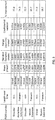
- FIG. 3 illustrates an exemplary table indicating body segment length statistics for ROM exercises for 10 subjects, according to an embodiment of the present disclosure. More particularly, FIG. 3 depicts correction and/or percentage (%) improvement in body segment length each ROM exercise with respect to mean (in meter), standard deviation (in meter), range (in meter), co-efficient of variation for input data obtained from a Kinect® sensor. As depicted in FIG. 3 , for example, for Shoulder ROM exercise (Abduction Adduction), the percentage (%) improvement in body segment length is 73.8 and 74.3 respectively. Similarly, for Shoulder ROM exercise (Flexion and Extension), the percentage (%) improvement in body segment length is 72.9 and 80.7 respectively. Likewise, for Elbow ROM exercise (Flexion and Extension) the percentage (%) improvement in body segment length is 71.6 and 58.7 respectively.
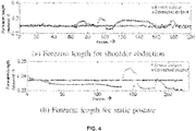
- FIG. 4 illustrates a graphical representation of variation in length of forearm joints in accordance with an embodiment of the present disclosure. More specifically, FIG. 4 depicts variation in length between elbow left and wrist left joints.
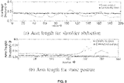
- FIG. 5 illustrates a graphical representation of variation in length of arm in accordance with an embodiment of the present disclosure. More specifically, FIG. 5 depicts variation in length between shoulder left and elbow left joints. The performance is evaluated by the system 100 both for stationary and dynamic joints.
- FIGS. 4 and 5 indicate a significant reduction in temporal variation of arm and forearm length during shoulder abduction, with the proposed methodology.
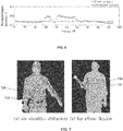
- FIG. 6 illustrates a graphical representation of variation in forearm length for elbow flexion in accordance with an embodiment of the present disclosure.
- FIG. 6 clearly shows similar trend for elbow flexion and extension.
- Performance comparison of length variation is carried out for all subjects using the following metrics - mean, standard deviation, range and coefficient of variation (CV) as depicted in the table of FIG. 3 .
- the results reported in the table of FIG. 3 indicate a clear reduction in standard deviation of body segment length from the order of 1-2 centimeters for Kinect skeleton data to a few millimeters for corrected skeleton data.
- CV coefficient of variation
- FIG. 7 depicts Body segment orientation correction by the system 100 of FIG. 1 in accordance with an embodiment of the present disclosure. More specifically, FIG. 7 depicts body segment orientation wherein dotted line denotes Kinect ⁇ output 702, solid line denotes correction 704 by the system 100.
- the corrected joint information not only helps achieve higher accuracy of measurements for joint Range of Motion analysis, but also aids in improving reliability of other assessment (e.g., clinical) of posture, gait, balance etc. from Kinect® skeleton information (or Kinect® Skeletal data).
- Kinect® skeleton information or Kinect® Skeletal data.
- the body segment orientation obtained from raw Kinect® coordinates often suffers from inaccuracy during motion, an example of which is shown in FIG.
- the systems and methods of the present disclosure provide techniques to improve accuracy of Kinect® skeletal joint coordinates for various applications (e.g., but are not limited to, rehabilitation).
- the Kinect® skeleton being a non-anthropometric model, there are body segment length and orientation variations over time.
- the proposed method implemented by the system 100 achieves and improves accuracy in estimation of body segment length as well as aligns the coordinates in the direction of the physical body segment that helps reconstruct the dynamic trajectory and angle of the body segment motion as accurately as possible.
- embodiments of the present disclosure describe body joint location identification in a 3D space, the embodiments/method may be implemented by the system 100 to identify body joint location in 2D space (or N-dimensions) as well.
- the hardware device can be any kind of device which can be programmed including e.g. any kind of computer like a server or a personal computer, or the like, or any combination thereof.
- the device may also include means which could be e.g. hardware means like e.g. an application-specific integrated circuit (ASIC), a field-programmable gate array (FPGA), or a combination of hardware and software means, e.g.
- ASIC application-specific integrated circuit
- FPGA field-programmable gate array
- the means can include both hardware means and software means.
- the method embodiments described herein could be implemented in hardware and software.
- the device may also include software means.
- the embodiments may be implemented on different hardware devices, e.g. using a plurality of CPUs.
- the embodiments herein can comprise hardware and software elements.
- the embodiments that are implemented in software include but are not limited to, firmware, resident software, microcode, etc.
- the functions performed by various modules described herein may be implemented in other modules or combinations of other modules.
- a computer-usable or computer readable medium can be any apparatus that can comprise, store, communicate, propagate, or transport the program for use by or in connection with the instruction execution system, apparatus, or device.
- a computer-readable storage medium refers to any type of physical memory on which information or data readable by a processor may be stored.
- a computer-readable storage medium may store instructions for execution by one or more processors, including instructions for causing the processor(s) to perform steps or stages consistent with the embodiments described herein.
- the term "computer-readable medium” should be understood to include tangible items and exclude carrier waves and transient signals, i.e., be non-transitory. Examples include random access memory (RAM), read-only memory (ROM), volatile memory, nonvolatile memory, hard drives, CD ROMs, DVDs, flash drives, disks, and any other known physical storage media.
Landscapes
- Engineering & Computer Science (AREA)
- Health & Medical Sciences (AREA)
- Life Sciences & Earth Sciences (AREA)
- Physics & Mathematics (AREA)
- Computer Vision & Pattern Recognition (AREA)
- General Health & Medical Sciences (AREA)
- Theoretical Computer Science (AREA)
- General Physics & Mathematics (AREA)
- Medical Informatics (AREA)
- Pathology (AREA)
- Veterinary Medicine (AREA)
- Surgery (AREA)
- Molecular Biology (AREA)
- Physiology (AREA)
- Heart & Thoracic Surgery (AREA)
- Biomedical Technology (AREA)
- Public Health (AREA)
- Biophysics (AREA)
- Animal Behavior & Ethology (AREA)
- Radiology & Medical Imaging (AREA)
- Nuclear Medicine, Radiotherapy & Molecular Imaging (AREA)
- Oral & Maxillofacial Surgery (AREA)
- Dentistry (AREA)
- Psychiatry (AREA)
- Quality & Reliability (AREA)
- Artificial Intelligence (AREA)
- Signal Processing (AREA)
- Geometry (AREA)
- Probability & Statistics with Applications (AREA)
- Software Systems (AREA)
- Multimedia (AREA)
- Human Computer Interaction (AREA)
- Social Psychology (AREA)
- Measurement Of The Respiration, Hearing Ability, Form, And Blood Characteristics Of Living Organisms (AREA)
- Length Measuring Devices With Unspecified Measuring Means (AREA)
- Image Analysis (AREA)
Abstract
Description
- This patent application claims priority to India Patent Application
201621027388, filed on August 10, 2016 - The disclosure herein generally relate to sensor data analysis, and, more particularly, to systems and methods for identifying body joint locations based on sensor data analysis.
- Joint motion analysis is an important aspect of health monitoring / rehabilitation of patients suffering from neurological disorders, post stroke patients, and elderly subjects. Joint movement data capture is traditionally done using clinical devices such as Vicon, which is marker-based and extremely expensive and ill-suited for prolonged rehabilitation therapy. Kinect® is a marker-less motion capture device that is being used for its low cost, portability and ease of cost when compared to its expensive counterpart. The accuracy of Kinect® as an alternative to Marker-based systems has been widely studied and there are extensive reports on its validity and reliability in comparison to Vicon. However, the reports indicate a lower accuracy of the human body joint information provided by Kinect® skeletal data. The skeleton data provided by Kinect® requires further optimization to improve its accuracy and allow effective and reliable assessment.
- Embodiments of the present disclosure present technological improvements as solutions to one or more of the above-mentioned technical problems recognized by the inventors in conventional systems. For example, in an aspect, a hardware processor implemented method for identifying body joint locations is provided. The method comprises obtaining, by one or more hardware processors, input data comprising skeletal data, depth data, and red, green, and blue (RGB) data pertaining to at least one user at one or more time stamps, wherein the one or more input data comprises three dimensional (3D) coordinates pertaining to one or more skeleton joints. The method further comprises estimating, using the one or more input data, by the one or more hardware processors, one or more body joint locations and a body segment length of one or more body segments connected to corresponding skeleton joints to obtain (i) an estimate of one or more body joint locations and (ii) an estimate of one or more body segment lengths. In an embodiment, the one or more body segment lengths are based on a Euclidean distance between adjacent skeleton joints. One or more probable correct body joint locations are identified in a bounded neighborhood around the one or more body joint locations that are previously obtained in a previous frame, wherein the one or more probable correct body joint locations are iteratively identified based on the depth data and the RGB data. In an example embodiment, a search region is defined for identifying the one or more probable correct body joint locations using a radius equivalent to a displacement of a corresponding skeleton joint in a single frame. The method further comprises performing, by the one or more hardware processors, a comparison of (i) a body segment length associated with each of the one or more probable correct body joint locations and (ii) a reference length. In an embodiment, the reference length is derived based on the estimate of the one or more body segment lengths. A subset of the one or more probable correct body joint locations are identified as one or more candidate body joint locations based on the comparison. In an embodiment, the subset of the one or more probable correct body joint locations are identified as one or more candidate body joint locations based on the comparison resulting in a minimal body segment length variation. A physical orientation of each body segment pertaining to each of the one or more candidate body joint locations is determined by segmenting one or more 3D coordinates of each body segment based on the depth data and performing an analysis on each segmented 3D coordinate. A (corrected) body joint location is identified from the one or more candidate body joint locations based on a minimal deviation in direction from the physical orientation of a corresponding body segment along with a feature descriptor of the RGB data and the depth data, wherein the minimal deviation is based on the depth data, and, wherein the minimal deviation is based on one or more actions performed by the user.
- In another aspect, a system for identifying a body joint location is provided. The system comprises a memory storing instructions, one or more communication interfaces, and one or more hardware processors coupled to the memory using the one or more communication interfaces, wherein the one or more hardware processors are configured by the instructions to: obtain one or more input data comprising skeletal data, depth data and red, green, and blue (RGB) data pertaining to at least one user at one or more time stamps, wherein the one or more input data comprising three dimensional (3D) coordinates pertaining to one or more skeleton joints. The skeletal data, depth data and red, green, and blue (RGB) data are captured by a sensor (e.g., Kinect® sensor). The one or more hardware processors are further configured by the instructions to estimate, using the one or more input data, one or more body joint locations and a body segment length of one or more body segments connecting to corresponding skeleton joints to obtain (i) an estimate of one or more body joint locations and (ii) an estimate of one or more body segment lengths. In an embodiment, one or more body segment lengths are based on a Euclidean distance between adjacent skeleton joints. In an embodiment, the system is further configured to identify one or more probable correct body joint locations in a bounded neighborhood around the one or more body joint locations that are previously obtained from a previous frame, wherein the one or more probable correct body joint locations are iteratively identified based on the depth data and the RGB data. In an embodiment, a search region is defined to identify the one or more probable correct body joint locations based on a radius equivalent to a displacement of a corresponding skeleton joint in a single frame.
- The system further performs a comparison of (i) a body segment length associated with each of the one or more probable correct body joint locations and (ii) a reference length. In an embodiment, the reference length is derived based on the estimate of the one or more body segment lengths. The system further identifies a subset of the one or more probable correct body joint locations as one or more candidate body joint locations based on the comparison. In an embodiment, the subset of the one or more probable correct body joint locations are identified as one or more candidate body joint locations based on the comparison resulting in a minimal body segment length variation. In other words, probable correct body joint locations having a minimal body segment length variation with respect to the reference length are identified as one or more candidate body joint locations.
- The system is further configured to determine a physical orientation of each body segment pertaining to each of the one or more candidate body joint locations by segmenting one or more 3D coordinates of each body segment based on the depth data and performing an analysis on each segmented 3D coordinate. The system is further configured to identify, from the one or more candidate body joint locations, a (corrected) body joint location based on a minimal deviation in direction from the physical orientation of a corresponding body segment along with a feature descriptor of the RGB data and the depth data, wherein the minimal deviation is based on the depth data, and wherein the minimal deviation is based on one or more actions performed by the user. In an embodiment, a body joint location having a minimal deviation in direction from the physical orientation of a corresponding body segment is identified as a corrected joint body location along with a feature descriptor of the RGB data and the depth data.
- In yet another aspect, one or more non-transitory machine readable information storage mediums comprising one or more instructions is provided. The one or more instructions which when executed by one or more hardware processors causes obtaining input data comprising skeletal data, depth data and red, green, and blue (RGB) data pertaining to at least one user at one or more time stamps, wherein the input data comprises three dimensional (3D) coordinates pertaining to one or more skeleton joints. The one or more instructions which when executed by one or more hardware processors further causes estimating, using the one or more input data, one or more body joint locations and a body segment length of one or more body segments connecting to corresponding skeleton joints to obtain (i) an estimate of one or more body joint locations and (ii) an estimate of one or more body segment lengths. In an embodiment, the one or more body segment lengths are based on a Euclidean distance between adjacent skeleton joints. The one or more instructions which when executed by one or more hardware processors causes identifying one or more probable correct body joint locations in a bounded neighborhood around the one or more body joint locations that are previously obtained, wherein the one or more probable correct body joint locations are iteratively identified based on the depth data and the RGB data. In an example embodiment, a search region is defined for identifying the one or more probable correct body joint locations using a radius equivalent to a displacement of a corresponding skeleton joint. The one or more instructions which when executed by one or more hardware processors further causes performing a comparison of (i) a body segment length associated with each of the one or more probable correct body joint locations and (ii) a reference length. In an embodiment, the reference length is derived based on the estimate of the one or more estimated body segment lengths. The one or more instructions which when executed by one or more hardware processors further causes identifying a subset of the one or more probable correct body joint locations as one or more candidate body joint locations based on the comparison. In an embodiment, identifying a subset of the one or more probable correct body joint locations as one or more candidate body joint locations is based on the comparison resulting in a minimal body segment length variation. The one or more instructions which when executed by one or more hardware processors further causes determining a physical orientation of each body segment pertaining to each of the one or more candidate body joint locations by segmenting one or more 3D coordinates of each body segment based on the depth data and performing an analysis on each segmented 3D coordinate. The one or more instructions which when executed by one or more hardware processors further causes identifying, from the one or more candidate body joint locations, a (corrected) body joint location based on a minimal deviation in direction from the physical orientation of a corresponding body segment along with a feature descriptor of the RGB data and the depth data, wherein said minimal deviation is based on the depth data, and, wherein the minimal deviation is based on one or more actions performed by the user.
- It is to be understood that both the foregoing general description and the following detailed description are exemplary and explanatory only and are not restrictive of the invention, as claimed.
- The accompanying drawings, which are incorporated in and constitute a part of this disclosure, illustrate exemplary embodiments and, together with the description, serve to explain the disclosed principles:
-
FIG. 1 illustrates an exemplary block diagram of a system for identifying a body joint location of a user in accordance with an embodiment of the present disclosure. -
FIG. 2 illustrates an exemplary flow diagram of a method for identifying a body joint location of a user using the system ofFIG. 1 in accordance with an embodiment of the present disclosure. -
FIG. 3 illustrates an exemplary table indicating body segment length statistics for ROM exercises for 10 subjects, according to an embodiment of the present disclosure. -
FIG. 4 illustrates a graphical representation of variation in length of forearm joints in accordance with an embodiment of the present disclosure. -
FIG. 5 illustrates a graphical representation of variation in length of arm in accordance with an embodiment of the present disclosure. -
FIG. 6 illustrates a graphical representation of variation in forearm length for elbow flexion in accordance with an embodiment of the present disclosure. -
FIG. 7 depicts Body segment orientation correction by the system ofFIG. 1 in accordance with an embodiment of the present disclosure. - Exemplary embodiments are described with reference to the accompanying drawings. In the figures, the left-most digit(s) of a reference number identifies the figure in which the reference number first appears. Wherever convenient, the same reference numbers are used throughout the drawings to refer to the same or like parts. While examples and features of disclosed principles are described herein, modifications, adaptations, and other implementations are possible without departing from the spirit and scope of the disclosed embodiments. It is intended that the following detailed description be considered as exemplary only, with the true scope and spirit being indicated by the following claims.
- Body joint movement analysis is extremely essential for health monitoring and treatment of patients with neurological disorders and stroke. Chronic hemiparesis of the upper extremity following a stroke causes major hand movement limitations. There is possibility of permanent reduction in muscle co-activation and corresponding joint torque patterns due to stroke. Several studies suggest that abnormal coupling of shoulder abductors with elbow flexors, and shoulder adductors with elbow extensors often leads to some stereotypical movement characteristics exhibited by severe stroke patients. Therefore continuous and effective rehabilitation therapy is absolutely essential to monitor and control such abnormalities. There is a substantial need for home-based rehabilitation post-clinical therapy.
- Marker-based systems for human body motion capture and analysis, (such as Vicon) are popular in upper extremity rehabilitation for their clinically approved levels of accuracy. But marker less systems for motion capture, such as Microsoft Kinect®, are feasible for home-based rehabilitation due to their affordability and portability. The accuracy, validity and test-retest reliability measures of Kinect have been studied for range of motion, postural control and gait. The results reported indicate a disparity between body joint locations observed by Kinect and that obtained by a clinical gold standard stereophotogrammetry system such as Vicon. Body segment length variations of the order of 6-8 centimeters (cms) for arm, and 2-5 cms for forearm were reported while using Kinect® as it provides a non-anthropometric skeleton model. Moreover the error was found to be lower for upper body than lower body joints. The performance of Kinect® has also been studied for non-healthy subjects and elderly population Experimental results showed that the accuracy of Kinect® for measuring gross spatial movement, such as shoulder and elbow movement, was higher than that for fine movements (such as hands). The disparity in body semantics such as body segment length and orientation increases during movement. It is therefore essential to improve accuracy of Kinect® in measurements related to clinical assessment and biomechanical modeling. For example, accurate measurement of arm length is important for assessing performance of reaching task for patients with impairments in the paretic arm. Prior work has been done on categorizing patients from movement pattern using only bone length derived from Kinect® skeleton data. Some had explicitly mentioned the need of further optimization of joint positions and body segment length using additional depth information from Kinect®.
- The embodiments of the present disclosure aims at improving accuracy of Kinect® in rehabilitation for upper extremities such as shoulder and elbow joints by improving joint center localization using additional Depth and RGB (RGBD) data, with constraints on body segment length and orientation. More particularly, the embodiments of the present disclosure implement systems and methods for sensor data analysis based identification of a body joint location that enables minimizing temporal variation in body segment length based on RGB and depth information obtained from Kinect® sensor, aligns connected joint pairs in the direction of physical body segment orientation using Depth-based segmentation and analysis (e.g., Principal Component Analysis (PCA)) on segmented 3D coordinates, and provides reliable range of motion analysis system based on corrected joint information.
- Referring now to the drawings, and more particularly to
FIGS. 1 through 7 , where similar reference characters denote corresponding features consistently throughout the figures, there are shown preferred embodiments and these embodiments are described in the context of the following exemplary system and/or method. -
FIG. 1 illustrates an exemplary block diagram of asystem 100 for identifying a body joint location of a user in accordance with an embodiment of the present disclosure. In an embodiment, thesystem 100 includes one ormore processors 104, communication interface device(s) or input/output (I/O) interface(s) 106, and one or more data storage devices ormemory 102 operatively coupled to the one ormore processors 104. The one ormore processors 104 that are hardware processors can be implemented as one or more microprocessors, microcomputers, microcontrollers, digital signal processors, central processing units, state machines, logic circuitries, and/or any devices that manipulate signals based on operational instructions. Among other capabilities, the processor(s) is configured to fetch and execute computer-readable instructions stored in the memory. In an embodiment, thesystem 100 can be implemented in a variety of computing systems, such as laptop computers, notebooks, hand-held devices, workstations, mainframe computers, servers, a network cloud and the like. - The I/O interface device(s) 106 can include a variety of software and hardware interfaces, for example, a web interface, a graphical user interface, and the like and can facilitate multiple communications within a wide variety of networks N/W and protocol types, including wired networks, for example, LAN, cable, etc., and wireless networks, such as WLAN, cellular, or satellite. In an embodiment, the I/O interface device(s) can include one or more ports for connecting a number of devices to one another or to another server.
- The
memory 102 may include any computer-readable medium known in the art including, for example, volatile memory, such as static random access memory (SRAM) and dynamic random access memory (DRAM), and/or non-volatile memory, such as read only memory (ROM), erasable programmable ROM, flash memories, hard disks, optical disks, and magnetic tapes. In an embodiment, one or more modules (not shown) of thesystem 100 can be stored in thememory 102. -
FIG. 2 illustrates an exemplary flow diagram of a method for identifying a body joint location of a user using thesystem 100 ofFIG. 1 in accordance with an embodiment of the present disclosure. In an embodiment, thesystem 100 comprises one or more data storage devices or thememory 102 operatively coupled to the one ormore hardware processors 104 and is configured to store instructions for execution of steps of the method by the one ormore processors 104. The steps of the method of the present disclosure will now be explained with reference to the components of thesystem 100 as depicted inFIG. 1 , and the flow diagram. In an embodiment of the present disclosure, atstep 202, the one ormore processors 104 obtain input data comprising skeletal data, depth data and red, green, and blue (RGB) data pertaining to at least one user. In an example embodiment, the input data may be captured at one or more time stamps. In an example embodiment, the one or more input data comprises three dimensional (3D) coordinates pertaining to one or more skeleton joints. In an example embodiment, the input data comprising skeletal data, depth data and red, green, and blue (RGB) data is captured by a sensor, for example, a Kinect® sensor. In an example embodiment, the skeletal data, depth data and red, green, and blue (RGB) data is received from the Kinect© sensor at a frame rate of approximately 25-30 frames per second The Kinect© sensor may be integrated within thesystem 100, in one example embodiment. The Kinect® sensor may be an external component that is connected to thesystem 100 via one or more communication interfaces, in another example embodiment. - In an embodiment of the present disclosure, at
step 204, the one ormore processors 104 estimate (or compute) one or more body joint locations and a body segment length of one or more body segments connected to corresponding skeleton joints to obtain (i) an estimate of one or more estimated body joint locations and (ii) an estimate of one or more estimated body segment lengths. In an embodiment, the one or more body segment lengths are based on a Euclidean distance between adjacent skeleton joints in the skeleton data input. In an example embodiment, the estimate of the body joint locations and the body segment lengths are obtained using the input data. - In an embodiment of the present disclosure, at
step 206, the one ormore processors 104 iteratively identify one or more probable correct body joint locations in a bounded neighborhood around the one or more body joint locations that are previously obtained from a previous frame. In one embodiment of the present disclosure, the one or more probable correct body joint locations are iteratively identified based on the depth data and the RGB data. In an example embodiment of the present disclosure, a search region is defined for identifying the one or more probable correct body joint locations using a radius equivalent to a displacement of a corresponding skeleton joint in a single frame. In an embodiment of the present disclosure, atstep 208, the one ormore processors 104 perform a comparison of (i) a body segment length associated with each of the one or more probable correct body joint locations and (ii) a reference length. In an example embodiment, the reference length is computed or derived based on the estimate of the one or more body segment lengths (e.g., true body segment lengths). In other words, the reference length is computed or derived based on Euclidean distance between body joint locations during system initialization. The initial estimates of the body joint locations (e.g., true body joint locations) and the reference length of body segment are computed by taking the average of input skeleton joint location and Euclidean distance between adjacent input joint locations respectively, after removing outliers, if any. - In an embodiment of the present disclosure, at
step 210, the one ormore processors 104 identify at least a subset of the one or more probable correct body joint locations as one or more candidate body joint locations based on the comparison. In an example of the present disclosure, the subset of the one or more probable correct body joint locations are identified as one or more candidate body joint locations based on the comparison resulting in a minimal body segment length variation. In other words, probable correct body joint locations having a minimal body segment length variation with respect to the reference length are identified as the one or more candidate body joint locations. - In an embodiment of the present disclosure, at
step 212, the one ormore processors 104 determine a physical orientation of each body segment pertaining to each of the one or more candidate body joint locations by segmenting one or more 3D coordinates of each body segment based on the depth data and performing an analysis on each segmented 3D coordinate. In one embodiment of the present disclosure, thesystem 100 performs a principle component analysis on each segmented 3D coordinate, based on which the physical orientation is determined. In an embodiment of the present disclosure, atstep 214, the one ormore processors 104 identify a corrected body joint location from the one or more candidate body joint locations based on a deviation in direction from the physical orientation of a corresponding body segment along with a feature descriptor of the RGB data and the depth data, wherein the minimal deviation is based on the depth data. In an example embodiment of the present disclosure, thesystem 100 uses the RGB-D based feature descriptor to identify a corrected body joint location having (or that has) a minimal deviation in direction from the physical orientation of a corresponding body segment (as depicted inFIG. 7 ). In an embodiment, the minimal deviation is based on, or subject to, one or more actions performed by the user. - Ten healthy subjects (age: 21-65 years, weight: 45kg - 120kg and height: 1:42m - 1:96m) with no pre-existing symptoms of neurological diseases, major orthopedic lesions or vestibular disorders, were chosen for the experiments. The Kinect® v1 device has been used to capture Depth, RGB and Skeleton data (at 25fps approximately) along with timestamp information. Participants/subjects stood at a distance of 2:1 meters - 2:4 meters from the Kinect® device (Kinect® sensor), which was placed 1 meter above the ground. Each participant performs the following (active) Range of motion (ROM) exercises - shoulder abduction and adduction, shoulder flexion and extension, elbow flexion and extension. In all experiments for an initial 1-2 seconds the subjects were required to stand completely stationary for initialization of the proposed methodology.
- Joint movement analysis using Kinect® sensor is based on spatiotemporal variation of three-dimensional coordinates of 20 skeleton joints given by:


B i,j represent the body segment connecting joints i and j. The joint coordinates are subject to noise due to room lighting (or any other ambient affecting conditions), infrared (IR) interferences, subject's distance from Kinect® sensor, quantization errors introduced during computations etc. The errors in joint center locations

B i,j, as well as its orientation in 3D space. - Hence, in order to reliably measure parameters such as joint range of motion, correct body joint locations are obtained that result in an accurate body segment length and orientation. With (direct) utilization of the depth sensor values as well as RGB information, it is possible to obtain the correct estimate of the joint's location that satisfies body segment length and orientation constraints. The intuition is that the correct location


FIG. 2 , for the body joint location that satisfies - (1) maximum similarity in time-varying characteristics of depth and RGB, represented by a proposed feature descriptor, (2) maximum alignment ofB i,j towards true physical body segment orientation, (which is estimated from depth segmentation and analysis such as principle component analysis), and (3) minimum deviation in ||B i,j || from reference length estimated during the initialization phase. - During the initialization phase when the subject(s) is made to remain stationary for 30 - 50 frames, an initial estimate of the body joint locations and the body segment length is computed based on quartile measures of observations. For each joint, candidate locations are searched in the vicinity of the Kinect® skeleton coordinates, which satisfy the constraint of minimal variation in length of body segment. Then the search is further refined by minimizing temporal variations in RGB-D based feature descriptor weighted by the deviation in direction of
B i,j from the physical orientation of the body segment. - In order to find depth and RGB value for a particular joint j, the real world coordinates


- The corrected body joint location


- The search is subject to the constraint that body segment length (the Euclidean distance between 3D coordinates of two physically connected joints) should remain invariant during movement of the corresponding joints. The search region S is refined to S1 by selecting candidate locations


system 100. In another example embodiment, one or more inputs may be obtained (e.g., from a user) by the system to define the search regions S and S1. - At each time instance t, the vector
B i,j is selected so that it exhibits maximum alignment towards the true body segment orientation. It is possible to segment the human body from the background in Kinect® Depth space. A bounded region around the body joint location of joints i and j is used to separate the coordinates of the body segment or limb from the rest of the human (user) form. An analysis (e.g., but not limited to, principle component analysis) is performed over segmented coordinates to get an Eigen vectorE i,j whose direction represents the direction of maximum variation of coordinates representing the body segment.E i,j provides an estimate of the physical orientation of the body orientation in each instance of time. - The search region (or space) S1 consists of candidate locations among which the joint's actual location lies. In order to select the true body joint location (example, an exact or actual body joint location amongst the one or more candidate body joint locations), a set of features based on RGB and depth characteristics is used to uniquely identify the joint as it makes it's trajectory over time.
- During any ROM exercise, in-spite of variation of depth values for any joint, the relative depth variation between a depth-pixel and its neighbors ought to remain unchanged for any two consecutive frames. The RGB values in a pixel neighborhood demonstrate similar properties. For a joint centre


P = (px,py) T and is expressed as
Q .


P with variance σ 2. - Similarly λ R centered at


- Finally the corrected location


-
FIG. 3 , with respect toFIGS. 1-2 , illustrates an exemplary table indicating body segment length statistics for ROM exercises for 10 subjects, according to an embodiment of the present disclosure. More particularly,FIG. 3 depicts correction and/or percentage (%) improvement in body segment length each ROM exercise with respect to mean (in meter), standard deviation (in meter), range (in meter), co-efficient of variation for input data obtained from a Kinect® sensor. As depicted inFIG. 3 , for example, for Shoulder ROM exercise (Abduction Adduction), the percentage (%) improvement in body segment length is 73.8 and 74.3 respectively. Similarly, for Shoulder ROM exercise (Flexion and Extension), the percentage (%) improvement in body segment length is 72.9 and 80.7 respectively. Likewise, for Elbow ROM exercise (Flexion and Extension) the percentage (%) improvement in body segment length is 71.6 and 58.7 respectively. -
FIG. 4 , with reference toFIGS. 1 through 3 , illustrates a graphical representation of variation in length of forearm joints in accordance with an embodiment of the present disclosure. More specifically,FIG. 4 depicts variation in length between elbow left and wrist left joints.FIG. 5 , with reference toFIGS. 1 through 4 , illustrates a graphical representation of variation in length of arm in accordance with an embodiment of the present disclosure. More specifically,FIG. 5 depicts variation in length between shoulder left and elbow left joints. The performance is evaluated by thesystem 100 both for stationary and dynamic joints.FIGS. 4 and5 indicate a significant reduction in temporal variation of arm and forearm length during shoulder abduction, with the proposed methodology. -
FIG. 6 , with reference toFIGS. 1 through 5 , illustrates a graphical representation of variation in forearm length for elbow flexion in accordance with an embodiment of the present disclosure.FIG. 6 clearly shows similar trend for elbow flexion and extension. Performance comparison of length variation is carried out for all subjects using the following metrics - mean, standard deviation, range and coefficient of variation (CV) as depicted in the table ofFIG. 3 . The results reported in the table ofFIG. 3 indicate a clear reduction in standard deviation of body segment length from the order of 1-2 centimeters for Kinect skeleton data to a few millimeters for corrected skeleton data. There is an average 72% improvement in CV over all ROM exercises and all subjects. -
FIG. 7 , with reference toFIGS. 1 through 6 , depicts Body segment orientation correction by thesystem 100 ofFIG. 1 in accordance with an embodiment of the present disclosure. More specifically,FIG. 7 depicts body segment orientation wherein dotted line denotes Kinect©output 702, solid line denotescorrection 704 by thesystem 100. The corrected joint information not only helps achieve higher accuracy of measurements for joint Range of Motion analysis, but also aids in improving reliability of other assessment (e.g., clinical) of posture, gait, balance etc. from Kinect® skeleton information (or Kinect® Skeletal data). The body segment orientation obtained from raw Kinect® coordinates often suffers from inaccuracy during motion, an example of which is shown inFIG. 7 where the 2D projection of the elbow and wrist skeletal coordinates is shown to exceed physical boundaries of the hand while the hand is in motion. This situation has been frequently observed during Range of Motion activities of multiple subjects. By correcting the orientation and length of body segment it is evident that the accuracy of dynamic measurement of joint angles is much higher. During range of motion exercise the corrected length and orientation of the limb may reflect the actual trajectory of the physical limb. It has been validated by the ROM measurement with a clinical Goniometer. For shoulder abduction the deviation of angle computed from Kinect® skeleton data is in the order of 6.39 degrees ± 5.06 degrees which eventually corresponds to the fact reported by conventional systems and methods, whereas the proposed method is able to reduce the deviation by 1.88 degrees ± 1.1 degrees. The proposed body segment length and orientation correction also influences joint angle and range of motion analysis. - The systems and methods of the present disclosure provide techniques to improve accuracy of Kinect® skeletal joint coordinates for various applications (e.g., but are not limited to, rehabilitation). The Kinect® skeleton being a non-anthropometric model, there are body segment length and orientation variations over time. The proposed method implemented by the
system 100 achieves and improves accuracy in estimation of body segment length as well as aligns the coordinates in the direction of the physical body segment that helps reconstruct the dynamic trajectory and angle of the body segment motion as accurately as possible. Although embodiments of the present disclosure describe body joint location identification in a 3D space, the embodiments/method may be implemented by thesystem 100 to identify body joint location in 2D space (or N-dimensions) as well. - The written description describes the subject matter herein to enable any person skilled in the art to make and use the embodiments. The scope of the subject matter embodiments is defined by the claims and may include other modifications that occur to those skilled in the art. Such other modifications are intended to be within the scope of the claims if they have similar elements that do not differ from the literal language of the claims or if they include equivalent elements with insubstantial differences from the literal language of the claims.
- It is to be understood that the scope of the protection is extended to such a program and in addition to a computer-readable means having a message therein; such computer-readable storage means contain program-code means for implementation of one or more steps of the method, when the program runs on a server or mobile device or any suitable programmable device. The hardware device can be any kind of device which can be programmed including e.g. any kind of computer like a server or a personal computer, or the like, or any combination thereof. The device may also include means which could be e.g. hardware means like e.g. an application-specific integrated circuit (ASIC), a field-programmable gate array (FPGA), or a combination of hardware and software means, e.g. an ASIC and an FPGA, or at least one microprocessor and at least one memory with software modules located therein. Thus, the means can include both hardware means and software means. The method embodiments described herein could be implemented in hardware and software. The device may also include software means. Alternatively, the embodiments may be implemented on different hardware devices, e.g. using a plurality of CPUs.
- The embodiments herein can comprise hardware and software elements. The embodiments that are implemented in software include but are not limited to, firmware, resident software, microcode, etc. The functions performed by various modules described herein may be implemented in other modules or combinations of other modules. For the purposes of this description, a computer-usable or computer readable medium can be any apparatus that can comprise, store, communicate, propagate, or transport the program for use by or in connection with the instruction execution system, apparatus, or device.
- The illustrated steps are set out to explain the exemplary embodiments shown, and it should be anticipated that ongoing technological development will change the manner in which particular functions are performed. These examples are presented herein for purposes of illustration, and not limitation. Further, the boundaries of the functional building blocks have been arbitrarily defined herein for the convenience of the description. Alternative boundaries can be defined so long as the specified functions and relationships thereof are appropriately performed. Alternatives (including equivalents, extensions, variations, deviations, etc., of those described herein) will be apparent to persons skilled in the relevant art(s) based on the teachings contained herein. Such alternatives fall within the scope and spirit of the disclosed embodiments. Also, the words "comprising," "having," "containing," and "including," and other similar forms are intended to be equivalent in meaning and be open ended in that an item or items following any one of these words is not meant to be an exhaustive listing of such item or items, or meant to be limited to only the listed item or items. It must also be noted that as used herein and in the appended claims, the singular forms "a," "an," and "the" include plural references unless the context clearly dictates otherwise.
- Furthermore, one or more computer-readable storage media may be utilized in implementing embodiments consistent with the present disclosure. A computer-readable storage medium refers to any type of physical memory on which information or data readable by a processor may be stored. Thus, a computer-readable storage medium may store instructions for execution by one or more processors, including instructions for causing the processor(s) to perform steps or stages consistent with the embodiments described herein. The term "computer-readable medium" should be understood to include tangible items and exclude carrier waves and transient signals, i.e., be non-transitory. Examples include random access memory (RAM), read-only memory (ROM), volatile memory, nonvolatile memory, hard drives, CD ROMs, DVDs, flash drives, disks, and any other known physical storage media.
- It is intended that the disclosure and examples be considered as exemplary only, with a true scope and spirit of disclosed embodiments being indicated by the following claims.
Claims (15)
- A processor implemented method, comprising:obtaining, by one or more hardware processors, one or more input data comprising skeletal data, depth data and red, green, and blue (RGB) data pertaining to at least one user at one or more time stamps, wherein said one or more input data comprises three dimensional (3D) coordinates pertaining to one or more skeleton joints;estimating, using said one or more input data, by said one or more hardware processors, in a first set of frames, one or more body joint locations and a body segment length of one or more body segments connected to corresponding skeleton joints to obtain (i) an estimate of one or more body joint locations and (ii) an estimate of one or more body segment lengths;iteratively identifying, by said one or more hardware processors, one or more probable correct body joint locations in a bounded neighborhood around said one or more body joint locations that are previously obtained, wherein said one or more probable correct body joint locations are iteratively identified based on said depth data and said RGB data;performing, by said one or more hardware processors, a comparison of (i) a body segment length associated with each of said one or more probable correct body joint locations and (ii) a reference length;identifying, by said one or more hardware processors, at least a subset of said one or more probable correct body joint locations as one or more candidate body joint locations based on said comparison;determining a physical orientation of each body segment pertaining to each of said one or more candidate body joint locations by segmenting one or more 3D coordinates of each body segment based on said depth data and performing an analysis on each segmented 3D coordinate; andidentifying, from said one or more candidate body joint locations, a body joint location based on a minimal deviation in direction from said physical orientation of a corresponding body segment along with a feature descriptor of said RGB data and said depth data, wherein said minimal deviation is based on said depth data, and wherein said minimal deviation is based on one or more actions performed by said user.
- The processor implemented method of claim 1, wherein identifying, by said one or more hardware processors, at least a subset of said one or more probable correct body joint locations as one or more candidate body joint locations is based on said comparison resulting in a minimal body segment length variation.
- The processor implemented method of claim 1, wherein a search region is defined for identifying said one or more probable correct body joint locations using a radius equivalent to a displacement of a corresponding skeleton joint.
- The processor implemented method of claim 1, wherein said estimate of said one or more body segment lengths is based on a Euclidean distance between adjacent skeleton joints.
- The processor implemented method of claim 1, wherein said reference length is derived based on said estimate of said one or more body segment lengths.
- A system comprising:a memory storing instructions;one or more communication interfaces; andone or more hardware processors coupled to said memory using said one or more communication interfaces, wherein said one or more hardware processors are configured by said instructions to:obtain one or more input data comprising skeletal data, depth data and red, green, and blue (RGB) data pertaining to at least one user at one or more time stamps, wherein said one or more input data comprising three dimensional (3D) coordinates pertaining to one or more skeleton joints,estimate, using said one or more input data, one or more body joint locations and a body segment length of one or more body segments connected to corresponding skeleton joints to obtain (i) an estimate of one or more body joint locations and (ii) an estimate of one or more body segment lengths,identify one or more probable correct body joint locations in a bounded neighborhood around said one or more body joint locations that are previously obtained, wherein said one or more probable correct body joint locations are iteratively identified based on said depth data and said RGB data,perform a comparison of (i) a body segment length associated with each of said one or more probable correct body joint locations and (ii) a reference length;identify at least a subset of said one or more probable correct body joint locations as one or more candidate body joint locations based on said comparison,determine a physical orientation of each body segment pertaining to each of said one or more candidate body joint locations by segmenting one or more 3D coordinates of each body segment based on said depth data and performing an analysis on each segmented 3D coordinate, andidentify, from said one or more candidate body joint locations, a body joint location based on a minimal deviation in direction from said physical orientation of a corresponding body segment along with a feature descriptor of said RGB data and said depth data, wherein said minimal deviation is based on said depth data, and wherein said minimal deviation is based on one or more actions performed by said user.
- The system of claim 6, wherein at least a subset of said one or more probable correct body joint locations are identified as one or more candidate body joint locations based on said comparison resulting in a minimal body segment length variation.
- The system of claim 6, wherein a search region is defined for identifying said one or more probable correct body joint locations based on a radius equivalent to a displacement of a corresponding skeleton joint.
- The system of claim 6, wherein said estimate of said one or more body segment lengths is based on a Euclidean distance between adjacent skeleton joints.
- The system of claim 6, wherein said reference length is derived based on said estimate of said one or more estimated body segment lengths.
- One or more non-transitory machine readable information storage mediums comprising one or more instructions which when executed by one or more hardware processors causes:obtaining, by one or more hardware processors, one or more input data comprising skeletal data, depth data and red, green, and blue (RGB) data pertaining to at least one user at one or more time stamps, wherein said one or more input data comprises three dimensional (3D) coordinates pertaining to one or more skeleton joints;estimating, using said one or more input data, by said one or more hardware processors, in a first set of frames, one or more body joint locations and a body segment length of one or more body segments connected to corresponding skeleton joints to obtain (i) an estimate of one or more body joint locations and (ii) an estimate of one or more body segment lengths;iteratively identifying, by said one or more hardware processors, one or more probable correct body joint locations in a bounded neighborhood around said one or more body joint locations that are previously obtained, wherein said one or more probable correct body joint locations are iteratively identified based on said depth data and said RGB data;performing, by said one or more hardware processors, a comparison of (i) a body segment length associated with each of said one or more probable correct body joint locations and (ii) a reference length;identifying, by said one or more hardware processors, at least a subset of said one or more probable correct body joint locations as one or more candidate body joint locations based on said comparison;determining a physical orientation of each body segment pertaining to each of said one or more candidate body joint locations by segmenting one or more 3D coordinates of each body segment based on said depth data and performing an analysis on each segmented 3D coordinate; andidentifying, from said one or more candidate body joint locations, a body joint location based on a minimal deviation in direction from said physical orientation of a corresponding body segment along with a feature descriptor of said RGB data and said depth data, wherein said minimal deviation is based on said depth data, and wherein said minimal deviation is based on one or more actions performed by said user.
- The one or more non-transitory machine readable information storage mediums of claim 11, wherein identifying, by said one or more hardware processors, at least a subset of said one or more probable correct body joint locations as one or more candidate body joint locations is based on said comparison resulting in a minimal body segment length variation.
- The one or more non-transitory machine readable information storage mediums claim 11, wherein a search region is defined for identifying said one or more probable correct body joint locations using a radius equivalent to a displacement of a corresponding skeleton joint.
- The one or more non-transitory machine readable information storage mediums of claim 11, wherein said estimate of said one or more body segment lengths is based on a Euclidean distance between adjacent skeleton joints.
- The one or more non-transitory machine readable information storage mediums of claim 11, wherein said reference length is derived based on said estimate of said one or more body segment lengths.
Applications Claiming Priority (1)
| Application Number | Priority Date | Filing Date | Title |
|---|---|---|---|
| IN201621027388 | 2016-08-10 |
Publications (2)
| Publication Number | Publication Date |
|---|---|
| EP3282421A1 true EP3282421A1 (en) | 2018-02-14 |
| EP3282421B1 EP3282421B1 (en) | 2020-09-23 |
Family
ID=58464162
Family Applications (1)
| Application Number | Title | Priority Date | Filing Date |
|---|---|---|---|
| EP17161945.5A Active EP3282421B1 (en) | 2016-08-10 | 2017-03-21 | Systems and methods for identifying body joint locations based on sensor data analysis |
Country Status (7)
| Country | Link |
|---|---|
| US (1) | US10068333B2 (en) |
| EP (1) | EP3282421B1 (en) |
| JP (1) | JP6862211B2 (en) |
| CN (1) | CN107729797B (en) |
| AU (1) | AU2017201137B2 (en) |
| SG (1) | SG10201701417TA (en) |
| ZA (1) | ZA201701187B (en) |
Cited By (2)
| Publication number | Priority date | Publication date | Assignee | Title |
|---|---|---|---|---|
| US20200093418A1 (en) * | 2018-09-21 | 2020-03-26 | Kineto Tech Rehab SRL | System and method for optimized monitoring of joints in physiotherapy |
| CN116152922A (en) * | 2023-01-03 | 2023-05-23 | 美的集团(上海)有限公司 | Human motion detection method, device, storage medium and computer program product |
Families Citing this family (10)
| Publication number | Priority date | Publication date | Assignee | Title |
|---|---|---|---|---|
| JP6433149B2 (en) * | 2013-07-30 | 2018-12-05 | キヤノン株式会社 | Posture estimation apparatus, posture estimation method and program |
| CN110634177A (en) * | 2018-06-21 | 2019-12-31 | 华为技术有限公司 | A kind of object modeling motion method, device and equipment |
| US11475630B2 (en) * | 2018-10-17 | 2022-10-18 | Midea Group Co., Ltd. | System and method for generating acupuncture points on reconstructed 3D human body model for physical therapy |
| CN109726672B (en) * | 2018-12-27 | 2020-08-04 | 哈尔滨工业大学 | A fall detection method based on human skeleton sequence and convolutional neural network |
| CN109815858B (en) * | 2019-01-10 | 2021-01-01 | 中国科学院软件研究所 | Target user gait recognition system and method in daily environment |
| CN109977827B (en) * | 2019-03-17 | 2020-11-13 | 浙江大学 | A multi-person 3D pose estimation method using a multi-view matching method |
| JP2023549242A (en) | 2021-03-19 | 2023-11-22 | シェンツェン・ショックス・カンパニー・リミテッド | Exercise monitoring method and system |
| US20230177881A1 (en) * | 2021-07-06 | 2023-06-08 | KinTrans, Inc. | Automatic body movement recognition and association system including smoothing, segmentation, similarity, pooling, and dynamic modeling |
| CN117814805B (en) * | 2024-03-05 | 2024-06-11 | 自贡市第一人民医院 | A method for intelligent processing of clinical nursing equipment data |
| CN120066278B (en) * | 2025-04-25 | 2025-07-01 | 陕西北斗天汇科技有限公司 | Human body 3D situation virtual sand table display control method and sand table display system |
Family Cites Families (16)
| Publication number | Priority date | Publication date | Assignee | Title |
|---|---|---|---|---|
| EP1663002A4 (en) * | 2003-09-19 | 2007-11-28 | Imaging Therapeutics Inc | BONE STRUCTURE PROGNOSTIC METHOD AND SIMULATED BONE REMODELING |
| US20140035805A1 (en) | 2009-04-02 | 2014-02-06 | David MINNEN | Spatial operating environment (soe) with markerless gestural control |
| CN101425140A (en) * | 2008-11-13 | 2009-05-06 | 苏州大学 | Encephalic angioma image recognizing and detecting method based on framework characteristic |
| US8523667B2 (en) * | 2010-03-29 | 2013-09-03 | Microsoft Corporation | Parental control settings based on body dimensions |
| US8351651B2 (en) * | 2010-04-26 | 2013-01-08 | Microsoft Corporation | Hand-location post-process refinement in a tracking system |
| CN102657532B (en) * | 2012-05-04 | 2014-09-17 | 深圳泰山在线科技有限公司 | Height measuring method and device based on body posture identification |
| US10234941B2 (en) * | 2012-10-04 | 2019-03-19 | Microsoft Technology Licensing, Llc | Wearable sensor for tracking articulated body-parts |
| JP6181373B2 (en) * | 2013-01-18 | 2017-08-16 | 東芝メディカルシステムズ株式会社 | Medical information processing apparatus and program |
| JP6433149B2 (en) * | 2013-07-30 | 2018-12-05 | キヤノン株式会社 | Posture estimation apparatus, posture estimation method and program |
| CN103473571B (en) | 2013-09-12 | 2017-01-25 | 天津大学 | Human detection method |
| CN103941857A (en) * | 2014-02-22 | 2014-07-23 | 浙江大学 | Self-adaptive interface generating method based on human bone extraction in gesture interaction |
| WO2015162158A1 (en) | 2014-04-22 | 2015-10-29 | Université Libre de Bruxelles | Human motion tracking |
| US10368784B2 (en) * | 2014-06-23 | 2019-08-06 | Microsoft Technology Licensing, Llc | Sensor data damping |
| DE102014013828A1 (en) | 2014-09-11 | 2016-03-31 | Motognosis UG (haftungsbeschränkt) | System and method for quantitative investigation of postural control of persons |
| CN104598890B (en) | 2015-01-30 | 2017-07-28 | 南京邮电大学 | A kind of Human bodys' response method based on RGB D videos |
| KR101639161B1 (en) * | 2015-06-24 | 2016-07-12 | 이화여자대학교 산학협력단 | Personal authentication method using skeleton information |
-
2017
- 2017-02-16 ZA ZA2017/01187A patent/ZA201701187B/en unknown
- 2017-02-17 JP JP2017027401A patent/JP6862211B2/en active Active
- 2017-02-20 AU AU2017201137A patent/AU2017201137B2/en active Active
- 2017-02-22 SG SG10201701417TA patent/SG10201701417TA/en unknown
- 2017-03-15 CN CN201710154869.5A patent/CN107729797B/en active Active
- 2017-03-21 EP EP17161945.5A patent/EP3282421B1/en active Active
- 2017-03-22 US US15/466,676 patent/US10068333B2/en active Active
Non-Patent Citations (2)
| Title |
|---|
| CHERYL D METCALF ET AL: "Markerless Motion Capture and Measurement of Hand Kinematics: Validation and Application to Home-Based Upper Limb Rehabilitation", IEEE TRANSACTIONS ON BIOMEDICAL ENGINEERING, IEEE SERVICE CENTER, PISCATAWAY, NJ, USA, vol. 60, no. 8, 1 August 2013 (2013-08-01), pages 2184 - 2192, XP011519800, ISSN: 0018-9294, DOI: 10.1109/TBME.2013.2250286 * |
| HO EDMOND S L ET AL: "Improving posture classification accuracy for depth sensor-based human activity monitoring in smart environments", COMPUTER VISION AND IMAGE UNDERSTANDING, ACADEMIC PRESS, US, vol. 148, 12 January 2016 (2016-01-12), pages 97 - 110, XP029556584, ISSN: 1077-3142, DOI: 10.1016/J.CVIU.2015.12.011 * |
Cited By (2)
| Publication number | Priority date | Publication date | Assignee | Title |
|---|---|---|---|---|
| US20200093418A1 (en) * | 2018-09-21 | 2020-03-26 | Kineto Tech Rehab SRL | System and method for optimized monitoring of joints in physiotherapy |
| CN116152922A (en) * | 2023-01-03 | 2023-05-23 | 美的集团(上海)有限公司 | Human motion detection method, device, storage medium and computer program product |
Also Published As
| Publication number | Publication date |
|---|---|
| JP6862211B2 (en) | 2021-04-21 |
| AU2017201137A1 (en) | 2018-03-01 |
| US20180047157A1 (en) | 2018-02-15 |
| CN107729797A (en) | 2018-02-23 |
| SG10201701417TA (en) | 2018-03-28 |
| US10068333B2 (en) | 2018-09-04 |
| CN107729797B (en) | 2021-04-09 |
| AU2017201137B2 (en) | 2021-11-18 |
| ZA201701187B (en) | 2019-07-31 |
| JP2018023749A (en) | 2018-02-15 |
| EP3282421B1 (en) | 2020-09-23 |
Similar Documents
| Publication | Publication Date | Title |
|---|---|---|
| EP3282421B1 (en) | Systems and methods for identifying body joint locations based on sensor data analysis | |
| US12226237B2 (en) | System and method for human gait analysis | |
| US11720185B2 (en) | Method and system for determining a correct reproduction of a movement | |
| EP3731185A1 (en) | Weakly supervised learning of 3d human poses from 2d poses | |
| US11354938B2 (en) | Motion tracking with multiple 3D cameras | |
| US20200372245A1 (en) | Scoring metric for physical activity performance and tracking | |
| CN109034095A (en) | A kind of face alignment detection method, apparatus and storage medium | |
| EP3425591A1 (en) | System and method for tracking body joints | |
| US20160324447A1 (en) | System and Method for Determining Orientation of Body Segments Using Inertial Measurement Units | |
| Bae et al. | Concurrent validity and test reliability of the deep learning markerless motion capture system during the overhead squat | |
| CN113361333B (en) | A non-contact cycling motion state monitoring method and system | |
| CN112699706A (en) | Fall detection method, system and storage medium | |
| US20160249866A1 (en) | Criteria for valid range of motion capture | |
| WO2016135560A2 (en) | Range of motion capture | |
| De Marchi et al. | Combining 3-D Human Pose Estimation and IMU Sensors for Human Identification and Tracking in Multiperson Environments | |
| US20200226788A1 (en) | Information processing apparatus, information processing method, and program | |
| US20250217986A1 (en) | Information processing system, information processing method, and program | |
| CN116250829A (en) | Motion posture evaluation method, device and electronic equipment | |
| EP4383194A1 (en) | Computer vision-assisted analysis of motion of a person | |
| US20250054184A1 (en) | Method and apparatus for estimating head rotation angle | |
| JP7862802B2 (en) | Posture evaluation device, posture evaluation system, posture evaluation method, and program | |
| US20260120315A1 (en) | Approaches to generating semi-synthetic training data for real-time estimation of pose and systems for implementing the same | |
| CN111435535A (en) | Method and device for acquiring joint point information | |
| Akhavizadegan et al. | Real-time automated contour based motion tracking using a single-camera for upper limb angular motion measurement | |
| Zheng et al. | A Real-time 3D Motion Detection System Based on A Monocular Camera |
Legal Events
| Date | Code | Title | Description |
|---|---|---|---|
| PUAI | Public reference made under article 153(3) epc to a published international application that has entered the european phase |
Free format text: ORIGINAL CODE: 0009012 |
|
| STAA | Information on the status of an ep patent application or granted ep patent |
Free format text: STATUS: THE APPLICATION HAS BEEN PUBLISHED |
|
| AK | Designated contracting states |
Kind code of ref document: A1 Designated state(s): AL AT BE BG CH CY CZ DE DK EE ES FI FR GB GR HR HU IE IS IT LI LT LU LV MC MK MT NL NO PL PT RO RS SE SI SK SM TR |
|
| AX | Request for extension of the european patent |
Extension state: BA ME |
|
| STAA | Information on the status of an ep patent application or granted ep patent |
Free format text: STATUS: REQUEST FOR EXAMINATION WAS MADE |
|
| 17P | Request for examination filed |
Effective date: 20180406 |
|
| RBV | Designated contracting states (corrected) |
Designated state(s): AL AT BE BG CH CY CZ DE DK EE ES FI FR GB GR HR HU IE IS IT LI LT LU LV MC MK MT NL NO PL PT RO RS SE SI SK SM TR |
|
| RIN1 | Information on inventor provided before grant (corrected) |
Inventor name: CHAKRAVARTY, KINGSHUK Inventor name: SINHA, SANJANA Inventor name: BHOWMICK, BROJESHWAR Inventor name: DAS, ABHIJIT |
|
| RIN1 | Information on inventor provided before grant (corrected) |
Inventor name: DAS, ABHIJIT Inventor name: BHOWMICK, BROJESHWAR Inventor name: SINHA, SANJANA Inventor name: CHAKRAVARTY, KINGSHUK |
|
| GRAP | Despatch of communication of intention to grant a patent |
Free format text: ORIGINAL CODE: EPIDOSNIGR1 |
|
| STAA | Information on the status of an ep patent application or granted ep patent |
Free format text: STATUS: GRANT OF PATENT IS INTENDED |
|
| INTG | Intention to grant announced |
Effective date: 20191112 |
|
| RIN1 | Information on inventor provided before grant (corrected) |
Inventor name: CHAKRAVARTY, KINGSHUK Inventor name: SINHA, SANJANA Inventor name: DAS, ABHIJIT Inventor name: BHOWMICK, BROJESHWAR |
|
| GRAS | Grant fee paid |
Free format text: ORIGINAL CODE: EPIDOSNIGR3 |
|
| GRAJ | Information related to disapproval of communication of intention to grant by the applicant or resumption of examination proceedings by the epo deleted |
Free format text: ORIGINAL CODE: EPIDOSDIGR1 |
|
| GRAL | Information related to payment of fee for publishing/printing deleted |
Free format text: ORIGINAL CODE: EPIDOSDIGR3 |
|
| STAA | Information on the status of an ep patent application or granted ep patent |
Free format text: STATUS: REQUEST FOR EXAMINATION WAS MADE |
|
| INTC | Intention to grant announced (deleted) | ||
| GRAP | Despatch of communication of intention to grant a patent |
Free format text: ORIGINAL CODE: EPIDOSNIGR1 |
|
| STAA | Information on the status of an ep patent application or granted ep patent |
Free format text: STATUS: GRANT OF PATENT IS INTENDED |
|
| INTG | Intention to grant announced |
Effective date: 20200511 |
|
| GRAS | Grant fee paid |
Free format text: ORIGINAL CODE: EPIDOSNIGR3 |
|
| GRAA | (expected) grant |
Free format text: ORIGINAL CODE: 0009210 |
|
| STAA | Information on the status of an ep patent application or granted ep patent |
Free format text: STATUS: THE PATENT HAS BEEN GRANTED |
|
| AK | Designated contracting states |
Kind code of ref document: B1 Designated state(s): AL AT BE BG CH CY CZ DE DK EE ES FI FR GB GR HR HU IE IS IT LI LT LU LV MC MK MT NL NO PL PT RO RS SE SI SK SM TR |
|
| REG | Reference to a national code |
Ref country code: GB Ref legal event code: FG4D |
|
| REG | Reference to a national code |
Ref country code: CH Ref legal event code: EP |
|
| REG | Reference to a national code |
Ref country code: DE Ref legal event code: R096 Ref document number: 602017023968 Country of ref document: DE |
|
| REG | Reference to a national code |
Ref country code: IE Ref legal event code: FG4D |
|
| REG | Reference to a national code |
Ref country code: AT Ref legal event code: REF Ref document number: 1317151 Country of ref document: AT Kind code of ref document: T Effective date: 20201015 |
|
| REG | Reference to a national code |
Ref country code: CH Ref legal event code: NV Representative=s name: ISLER AND PEDRAZZINI AG, CH |
|
| REG | Reference to a national code |
Ref country code: NL Ref legal event code: FP |
|
| PG25 | Lapsed in a contracting state [announced via postgrant information from national office to epo] |
Ref country code: SE Free format text: LAPSE BECAUSE OF FAILURE TO SUBMIT A TRANSLATION OF THE DESCRIPTION OR TO PAY THE FEE WITHIN THE PRESCRIBED TIME-LIMIT Effective date: 20200923 Ref country code: BG Free format text: LAPSE BECAUSE OF FAILURE TO SUBMIT A TRANSLATION OF THE DESCRIPTION OR TO PAY THE FEE WITHIN THE PRESCRIBED TIME-LIMIT Effective date: 20201223 Ref country code: HR Free format text: LAPSE BECAUSE OF FAILURE TO SUBMIT A TRANSLATION OF THE DESCRIPTION OR TO PAY THE FEE WITHIN THE PRESCRIBED TIME-LIMIT Effective date: 20200923 Ref country code: FI Free format text: LAPSE BECAUSE OF FAILURE TO SUBMIT A TRANSLATION OF THE DESCRIPTION OR TO PAY THE FEE WITHIN THE PRESCRIBED TIME-LIMIT Effective date: 20200923 Ref country code: GR Free format text: LAPSE BECAUSE OF FAILURE TO SUBMIT A TRANSLATION OF THE DESCRIPTION OR TO PAY THE FEE WITHIN THE PRESCRIBED TIME-LIMIT Effective date: 20201224 Ref country code: NO Free format text: LAPSE BECAUSE OF FAILURE TO SUBMIT A TRANSLATION OF THE DESCRIPTION OR TO PAY THE FEE WITHIN THE PRESCRIBED TIME-LIMIT Effective date: 20201223 |
|
| REG | Reference to a national code |
Ref country code: AT Ref legal event code: MK05 Ref document number: 1317151 Country of ref document: AT Kind code of ref document: T Effective date: 20200923 |
|
| PG25 | Lapsed in a contracting state [announced via postgrant information from national office to epo] |
Ref country code: LV Free format text: LAPSE BECAUSE OF FAILURE TO SUBMIT A TRANSLATION OF THE DESCRIPTION OR TO PAY THE FEE WITHIN THE PRESCRIBED TIME-LIMIT Effective date: 20200923 Ref country code: RS Free format text: LAPSE BECAUSE OF FAILURE TO SUBMIT A TRANSLATION OF THE DESCRIPTION OR TO PAY THE FEE WITHIN THE PRESCRIBED TIME-LIMIT Effective date: 20200923 |
|
| REG | Reference to a national code |
Ref country code: LT Ref legal event code: MG4D |
|
| PG25 | Lapsed in a contracting state [announced via postgrant information from national office to epo] |
Ref country code: EE Free format text: LAPSE BECAUSE OF FAILURE TO SUBMIT A TRANSLATION OF THE DESCRIPTION OR TO PAY THE FEE WITHIN THE PRESCRIBED TIME-LIMIT Effective date: 20200923 Ref country code: RO Free format text: LAPSE BECAUSE OF FAILURE TO SUBMIT A TRANSLATION OF THE DESCRIPTION OR TO PAY THE FEE WITHIN THE PRESCRIBED TIME-LIMIT Effective date: 20200923 Ref country code: PT Free format text: LAPSE BECAUSE OF FAILURE TO SUBMIT A TRANSLATION OF THE DESCRIPTION OR TO PAY THE FEE WITHIN THE PRESCRIBED TIME-LIMIT Effective date: 20210125 Ref country code: CZ Free format text: LAPSE BECAUSE OF FAILURE TO SUBMIT A TRANSLATION OF THE DESCRIPTION OR TO PAY THE FEE WITHIN THE PRESCRIBED TIME-LIMIT Effective date: 20200923 Ref country code: LT Free format text: LAPSE BECAUSE OF FAILURE TO SUBMIT A TRANSLATION OF THE DESCRIPTION OR TO PAY THE FEE WITHIN THE PRESCRIBED TIME-LIMIT Effective date: 20200923 Ref country code: SM Free format text: LAPSE BECAUSE OF FAILURE TO SUBMIT A TRANSLATION OF THE DESCRIPTION OR TO PAY THE FEE WITHIN THE PRESCRIBED TIME-LIMIT Effective date: 20200923 |
|
| PG25 | Lapsed in a contracting state [announced via postgrant information from national office to epo] |
Ref country code: PL Free format text: LAPSE BECAUSE OF FAILURE TO SUBMIT A TRANSLATION OF THE DESCRIPTION OR TO PAY THE FEE WITHIN THE PRESCRIBED TIME-LIMIT Effective date: 20200923 Ref country code: IS Free format text: LAPSE BECAUSE OF FAILURE TO SUBMIT A TRANSLATION OF THE DESCRIPTION OR TO PAY THE FEE WITHIN THE PRESCRIBED TIME-LIMIT Effective date: 20210123 Ref country code: ES Free format text: LAPSE BECAUSE OF FAILURE TO SUBMIT A TRANSLATION OF THE DESCRIPTION OR TO PAY THE FEE WITHIN THE PRESCRIBED TIME-LIMIT Effective date: 20200923 Ref country code: AL Free format text: LAPSE BECAUSE OF FAILURE TO SUBMIT A TRANSLATION OF THE DESCRIPTION OR TO PAY THE FEE WITHIN THE PRESCRIBED TIME-LIMIT Effective date: 20200923 Ref country code: AT Free format text: LAPSE BECAUSE OF FAILURE TO SUBMIT A TRANSLATION OF THE DESCRIPTION OR TO PAY THE FEE WITHIN THE PRESCRIBED TIME-LIMIT Effective date: 20200923 |
|
| REG | Reference to a national code |
Ref country code: DE Ref legal event code: R097 Ref document number: 602017023968 Country of ref document: DE |
|
| PG25 | Lapsed in a contracting state [announced via postgrant information from national office to epo] |
Ref country code: SK Free format text: LAPSE BECAUSE OF FAILURE TO SUBMIT A TRANSLATION OF THE DESCRIPTION OR TO PAY THE FEE WITHIN THE PRESCRIBED TIME-LIMIT Effective date: 20200923 |
|
| PLBE | No opposition filed within time limit |
Free format text: ORIGINAL CODE: 0009261 |
|
| STAA | Information on the status of an ep patent application or granted ep patent |
Free format text: STATUS: NO OPPOSITION FILED WITHIN TIME LIMIT |
|
| PG25 | Lapsed in a contracting state [announced via postgrant information from national office to epo] |
Ref country code: SI Free format text: LAPSE BECAUSE OF FAILURE TO SUBMIT A TRANSLATION OF THE DESCRIPTION OR TO PAY THE FEE WITHIN THE PRESCRIBED TIME-LIMIT Effective date: 20200923 Ref country code: DK Free format text: LAPSE BECAUSE OF FAILURE TO SUBMIT A TRANSLATION OF THE DESCRIPTION OR TO PAY THE FEE WITHIN THE PRESCRIBED TIME-LIMIT Effective date: 20200923 |
|
| 26N | No opposition filed |
Effective date: 20210624 |
|
| PG25 | Lapsed in a contracting state [announced via postgrant information from national office to epo] |
Ref country code: IT Free format text: LAPSE BECAUSE OF FAILURE TO SUBMIT A TRANSLATION OF THE DESCRIPTION OR TO PAY THE FEE WITHIN THE PRESCRIBED TIME-LIMIT Effective date: 20200923 Ref country code: MC Free format text: LAPSE BECAUSE OF FAILURE TO SUBMIT A TRANSLATION OF THE DESCRIPTION OR TO PAY THE FEE WITHIN THE PRESCRIBED TIME-LIMIT Effective date: 20200923 |
|
| REG | Reference to a national code |
Ref country code: BE Ref legal event code: MM Effective date: 20210331 |
|
| PG25 | Lapsed in a contracting state [announced via postgrant information from national office to epo] |
Ref country code: IE Free format text: LAPSE BECAUSE OF NON-PAYMENT OF DUE FEES Effective date: 20210321 Ref country code: LU Free format text: LAPSE BECAUSE OF NON-PAYMENT OF DUE FEES Effective date: 20210321 |
|
| PG25 | Lapsed in a contracting state [announced via postgrant information from national office to epo] |
Ref country code: BE Free format text: LAPSE BECAUSE OF NON-PAYMENT OF DUE FEES Effective date: 20210331 |
|
| PG25 | Lapsed in a contracting state [announced via postgrant information from national office to epo] |
Ref country code: CY Free format text: LAPSE BECAUSE OF FAILURE TO SUBMIT A TRANSLATION OF THE DESCRIPTION OR TO PAY THE FEE WITHIN THE PRESCRIBED TIME-LIMIT Effective date: 20200923 |
|
| P01 | Opt-out of the competence of the unified patent court (upc) registered |
Effective date: 20230526 |
|
| PG25 | Lapsed in a contracting state [announced via postgrant information from national office to epo] |
Ref country code: HU Free format text: LAPSE BECAUSE OF FAILURE TO SUBMIT A TRANSLATION OF THE DESCRIPTION OR TO PAY THE FEE WITHIN THE PRESCRIBED TIME-LIMIT; INVALID AB INITIO Effective date: 20170321 |
|
| PG25 | Lapsed in a contracting state [announced via postgrant information from national office to epo] |
Ref country code: MK Free format text: LAPSE BECAUSE OF FAILURE TO SUBMIT A TRANSLATION OF THE DESCRIPTION OR TO PAY THE FEE WITHIN THE PRESCRIBED TIME-LIMIT Effective date: 20200923 |
|
| PG25 | Lapsed in a contracting state [announced via postgrant information from national office to epo] |
Ref country code: TR Free format text: LAPSE BECAUSE OF FAILURE TO SUBMIT A TRANSLATION OF THE DESCRIPTION OR TO PAY THE FEE WITHIN THE PRESCRIBED TIME-LIMIT Effective date: 20200923 |
|
| PG25 | Lapsed in a contracting state [announced via postgrant information from national office to epo] |
Ref country code: MT Free format text: LAPSE BECAUSE OF FAILURE TO SUBMIT A TRANSLATION OF THE DESCRIPTION OR TO PAY THE FEE WITHIN THE PRESCRIBED TIME-LIMIT Effective date: 20200923 |
|
| PGFP | Annual fee paid to national office [announced via postgrant information from national office to epo] |
Ref country code: CH Payment date: 20250401 Year of fee payment: 9 |
|
| REG | Reference to a national code |
Ref country code: CH Ref legal event code: U11 Free format text: ST27 STATUS EVENT CODE: U-0-0-U10-U11 (AS PROVIDED BY THE NATIONAL OFFICE) Effective date: 20260401 |
|
| PGFP | Annual fee paid to national office [announced via postgrant information from national office to epo] |
Ref country code: GB Payment date: 20260304 Year of fee payment: 10 |
|
| PGFP | Annual fee paid to national office [announced via postgrant information from national office to epo] |
Ref country code: DE Payment date: 20260320 Year of fee payment: 10 |
|
| PGFP | Annual fee paid to national office [announced via postgrant information from national office to epo] |
Ref country code: NL Payment date: 20260323 Year of fee payment: 10 |
|
| PGFP | Annual fee paid to national office [announced via postgrant information from national office to epo] |
Ref country code: FR Payment date: 20260323 Year of fee payment: 10 |