EP3282360A1 - Information processing device, relay device, information processing system, and software update method - Google Patents
Information processing device, relay device, information processing system, and software update method Download PDFInfo
- Publication number
- EP3282360A1 EP3282360A1 EP16776595.7A EP16776595A EP3282360A1 EP 3282360 A1 EP3282360 A1 EP 3282360A1 EP 16776595 A EP16776595 A EP 16776595A EP 3282360 A1 EP3282360 A1 EP 3282360A1
- Authority
- EP
- European Patent Office
- Prior art keywords
- version
- relay device
- firmware
- basic software
- information processing
- Prior art date
- Legal status (The legal status is an assumption and is not a legal conclusion. Google has not performed a legal analysis and makes no representation as to the accuracy of the status listed.)
- Granted
Links
Images


Classifications
-
- G—PHYSICS
- G06—COMPUTING OR CALCULATING; COUNTING
- G06F—ELECTRIC DIGITAL DATA PROCESSING
- G06F8/00—Arrangements for software engineering
- G06F8/60—Software deployment
- G06F8/65—Updates
-
- G—PHYSICS
- G06—COMPUTING OR CALCULATING; COUNTING
- G06F—ELECTRIC DIGITAL DATA PROCESSING
- G06F11/00—Error detection; Error correction; Monitoring
-
- G—PHYSICS
- G06—COMPUTING OR CALCULATING; COUNTING
- G06F—ELECTRIC DIGITAL DATA PROCESSING
- G06F13/00—Interconnection of, or transfer of information or other signals between, memories, input/output devices or central processing units
-
- G—PHYSICS
- G06—COMPUTING OR CALCULATING; COUNTING
- G06F—ELECTRIC DIGITAL DATA PROCESSING
- G06F13/00—Interconnection of, or transfer of information or other signals between, memories, input/output devices or central processing units
- G06F13/10—Program control for peripheral devices
- G06F13/102—Program control for peripheral devices where the program performs an interfacing function, e.g. device driver
-
- G—PHYSICS
- G06—COMPUTING OR CALCULATING; COUNTING
- G06F—ELECTRIC DIGITAL DATA PROCESSING
- G06F8/00—Arrangements for software engineering
- G06F8/70—Software maintenance or management
- G06F8/71—Version control; Configuration management
Definitions
- the present invention relates to techniques for updating basic software or firmware in an information processing system with which peripheral devices are connected.
- video image systems having a video image generation device such as a game machine or a personal computer connected with a head-mounted display device that presents its user with video images on a display panel in front of the user's eyes to enhance realistic sensation.
- Peripheral devices such as the head-mounted display device are operated using dedicated firmware.
- the firmware of a peripheral device needs to be updated independently of the basic software of the video image generation device with which the peripheral device is connected. However, the user may find it inconvenient if time is spent on updating the firmware of the peripheral device every time the video image generation device is started even though the peripheral device is not used.
- An object of the invention is to provide techniques for efficiently updating basic software or firmware in an information processing system with which peripheral devices are connected.
- an information processing device connected with a peripheral device via a relay device.
- the information processing device includes a version acquisition unit configured to acquire from the relay device information related to version of firmware installed in the relay device, a version comparison unit configured to compare the version of the firmware installed in the relay device with version of firmware requested by basic software installed in the information processing device, and an update request unit configured such that if the version of the firmware installed in the relay device is older than the version of the firmware requested by the basic software installed in the information processing device, the update request unit supplies the relay device with firmware for the relay device included in the basic software in order to update accordingly the firmware installed in the relay device.
- a relay device connecting a peripheral device to an information processing device.
- the relay device includes a version notification unit configured to acquire information related to version of firmware installed in the relay device and notify the information processing device of the information, and an update unit configured such that if the version of the firmware installed in the relay device is older than version of firmware requested by basic software installed in the information processing device, the update unit receives from the information processing device firmware for the relay device included in the basic software in order to update accordingly the firmware installed in the relay device.
- an information processing system including an information processing device and a relay device connecting a peripheral device to the information processing device.
- the information processing device includes a version acquisition unit configured to acquire from the relay device information related to version of firmware installed in the relay device, a version comparison unit configured to compare the version of the firmware installed in the relay device with version of firmware requested by basic software installed in the information processing device, and an update request unit configured such that if the version of the firmware installed in the relay device is older than the version of the firmware requested by the basic software installed in the information processing device, the update request unit supplies the relay device with firmware for the relay device included in the basic software in order to update accordingly the firmware installed in the relay device.
- the relay device includes a version notification unit configured to acquire the information related to the version of the firmware installed in the relay device and notify the information processing device of the information, and an update unit configured such that if the version of the firmware installed in the relay device is older than the version of the firmware requested by the basic software installed in the information processing device, the update unit receives from the information processing device the firmware for the relay device included in the basic software in order to update accordingly the firmware installed in the relay device.
- a software update method updating firmware of a relay device or basic software of an information processing device the relay device and the information processing device being included in an information processing system, the relay device being used to connect a peripheral device to the information processing device.
- the software update method includes a version acquisition step of acquiring from the relay device information related to version of firmware installed in the relay device, a version comparison step of comparing the version of the firmware installed in the relay device with version of firmware requested by the basic software installed in the information processing device, and an update request step of, if the version of the firmware installed in the relay device is older than the version of the firmware requested by the basic software installed in the information processing device, supplying the relay device with firmware for the relay device included in the basic software in order to update accordingly the firmware installed in the relay device.
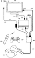
- FIG. 1 is a configuration diagram of a video image system as one embodiment.
- a video image generation device 300 is a typical information processing device according to the present application. More specifically, the video image generation device 300 is a game machine or a personal computer, for example, which generates video images by computer graphics. Although not shown, the video image generation device 300 may connect and communicate with networks to receive data from servers or to transmit data to other terminals.
- a camera 310 may be connected to the video image generation device 300 using a connection cable 240.
- a wireless controller 320 and a motion controller 330 may also be connected wirelessly to the video image generation device 300.
- a video image relay device 200 is connected to the video image generation device 300 via an interface such as a universal serial bus (USB) using a connection cable 230.
- a head-mounted display device 100 is connected to the video image relay device 200 using a dedicated cable 260.
- the head-mounted display device 100 is a typical peripheral device associated with the present application.
- a high-definition multimedia interface (HDMI; registered trademark) output terminal of the video image generation device 300 is connected with an HDMI input terminal of the video image relay device 200 via a connection cable 210.
- An HDMI output terminal of the video image relay device 200 is connected with an HDMI input terminal of a display device 400 via a connection cable 220.
- the video image relay device 200 is connected to a power source via a power cable 250. It is assumed here that the video image relay device 200 is always turned on. Obviously, if the head-mounted display device 100 acting as a peripheral device is not used, the video image relay device 200 may be turned off.
- the video image relay device 200 relays video images output from the video image generation device 300 to the display device 400 and to the head-mounted display device 100.
- the video images generated by the video image generation device 300 are output through the HDMI output terminal of the video image generation device 300 and input to the HDMI input terminal of the video image relay device 200 via the connection cable 210.
- the video images input to the HDMI input terminal of the video image relay device 200 are output unmodified from the HDMI output terminal of the video image relay device 200. From there, the video images are input to the HDMI input terminal of the display device 400 via the connection cable 220. At the same time, the video images input to the HDMI input terminal of the video image relay device 200 are converted to an image format suitable for the head-mounted display device 100, before being input to the head-mounted display device 100 via the dedicated cable 260.
- the video image relay device 200 relays the video images unmodified from the video image generation device 300 to the display device 400.
- the video image relay device 200 converts the video images coming from the video image generation device 300 into a format suitable for the head-mounted display device 100 before relaying the video images to the head-mounted display device 100. This allows the user wearing the head-mounted display device 100 to view the video images in front of his or her eyes, while enabling other users to view the video images conventionally on the display device 400.
- the video image relay device 200 thus functions as a converter-distributer that may convert as needed the video images coming from the video image generation device 300 before distributing them to multiple display devices.
- the basic software for executing the commands of applications such as games is installed in the video image generation device 300.
- the firmware for the head-mounted display device 100 is installed in the video image relay device 200.
- the basic software and the firmware need to be updated as needed.
- the data necessary for updating the basic software and the firmware is either read from a recording medium inserted in the video image generation device 300 and written to a storage area of the video image generation device 300, or downloaded from servers over networks into the storage area of the video image generation device 300.
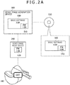
- FIGS. 2A to 2C are explanatory views showing steps of updating the firmware of the video image relay device 200.
- Basic software 500 installed in the video image generation device 300 includes firmware 510 to be installed in the video image relay device 200 for use by the head-mounted display device 100.
- This is a configuration similar to one in which the operating system of a computer includes the drivers of various peripheral devices. The driver for a peripheral device included in the operating system is read and installed into the computer when that peripheral device is configured for use.
- the firmware 510 for the head-mounted display device 100 included in the basic software 500 is installed into the video image relay device 200 before the head-mounted display device 100 is used.
- the basic software 500 of version 3.00 is initially installed in the video image generation device 300.
- the basic software 500 of version 3.00 includes the firmware 510 of version 1.00.
- Firmware 520 of version 1.00 is installed in the video image relay device 200.
- the head-mounted display device 100 is turned off.
- a recording medium 530 storing applications such as games is inserted in the video image generation device 300.
- the recording medium 530 stores the basic software of the latest version along with the applications.
- the recording medium 530 stores basic software 502 of version 4.00 that includes firmware 512 of version 2.00.
- the firmware 512 of version 2.00 is the firmware of the latest version of which the performance is confirmed by the basic software 502 of version 4.00.
- the video image generation device 300 compares the version of the basic software stored on the recording medium 530 with the version of the basic software already installed in the video image generation device 300. If the version of the basic software on the recording medium 530 is newer than the version of the basic software already installed in the video image generation device 300, the video image generation device 300 reads the basic software 502 of the latest version 4.00 from the recording medium 530 and updates the currently installed basic software accordingly.
- the basic software 502 stored on the recording medium 530 includes the firmware 512 of the latest version 2.00.
- the update brings the basic software 500 of the video image generation device 300 to version 4.00 and the firmware 510 included in the basic software 500 to version 2.00.
- the head-mounted display device 100 is turned off.
- the firmware 520 of the video image relay device 200 has yet to be updated; the firmware 520 of the old version 1.00 remains unchanged.
- the video image generation device 300 when the head-mounted display device 100 is turned on, the video image generation device 300 is notified of information about the version of the firmware 520 already installed in the video image relay device 200.
- the video image generation device 300 compares the version of the firmware 520 currently installed in the video image relay device 200 with the version of the firmware requested by the basic software 500 of the video image generation device 300. If the version of the firmware 520 in the video image relay device 200 is older than the version requested by the basic software 500 of the video mage generation device 300, the firmware 510 of the latest version included in the basic software 500 is supplied to the video image relay device 200 in order to update the firmware of the video image relay device 200.
- a predetermined region of the basic software 500 prescribes that the version of the firmware requested by the basic software 500 of the video image generation device 300 be version 2.00 or higher.
- the version of the firmware 520 currently installed in the video image relay device 200 is version 1.00, which is older than version 2.00.
- the firmware 510 of the latest version 2.00 included in the basic software 500 is supplied to the video image relay device 200 to bring the firmware 520 of the video image relay device 200 to version 2.00.
- the firmware 520 of the video image relay device 200 is not updated until the head-mounted display device 100 is turned on. Only when the head-mounted display device 100 is turned on, is the firmware 520 of the video image relay device 200 updated with the firmware 510 of the latest version included in the basic software 500 of the latest version in the video image generation device 300.
- the user may find it inconvenient if it is necessary to wait for the firmware 520 of the video image relay device 200 to be updated despite the user not using the head-mounted display device 100.
- the firmware update method of the present embodiment when the head-mounted display device 100 is turned on, i.e., at the time the head-mounted display device 100 is used, the firmware 520 of the video image relay device 200 is updated as needed. This method offers the advantage of not giving the user unnecessary frustration at the time of updating the firmware.
- FIGS. 3A to 3C are explanatory views showing steps of updating the basic software of the video image generation device 300.
- a video image generation device 300A of user A is connected with a video image relay device 200A that in turn is connected with a head-mounted display device 100A.
- Basic software 500A of version 4.00 is installed in the video image generation device 300A.
- the basic software 500A includes firmware 510A of version 2.00.
- Firmware 520A of version 2.00 is installed in the video image relay device 200A.
- User A disconnects the video image relay device 200A and the head-mounted display device 100A from the video image generation device 300A, and connects the disconnected devices to a video image generation device 300B of user B.
- the situation assumed here may be one in which user B is a friend of user A's and user A brings his or her video image relay device 200A and the head-mounted display device 100A from his or her place to user B's place.
- Basic software 500B of version 3.00 is installed in the video image generation device 300B of user B.
- the basic software 500B includes firmware 510B of version 1.00.
- the video image generation device 300B of user B is connected with the video image relay device 200A and the head-mounted display device 100A of user A.
- the version of the firmware 520A installed in the video image relay device 200A of user A is version 2.00
- the version of the basic software 500B installed in the video image generation device 300B is version 3.00.
- the basic software 500B of version 3.00 installed in the video image generation device 300B supports the firmware of version 1.00 but does not comply with the firmware 520A of the new version 2.00.
- the video image relay device 200A When the head-mounted display device 100A is turned on, the video image relay device 200A notifies the video image generation device 300B of information about the version of the basic software requested by the firmware 520A of version 2.00 installed in the video image relay device 200A. In this case, a predetermined region of the firmware prescribes that the firmware of version 2.00 request the basic software of version 4.00 or higher. This information is conveyed to the video image generation device 300B.
- the video image generation device 300B compares the version of the basic software conveyed from the video image relay device 200A and requested by the firmware 520A of the video image relay device 200A with the version of the basic software 500B in the video image generation device 300B. If the version of the basic software 500B is older than the version conveyed from the video image relay device 200A, the video image generation device 300B downloads the basic software 500B of a new version from a server 700 via a network 600 and installs the downloaded basic software.
- the version of the basic software requested by the firmware 520A of the video image relay device 200A is version 4.00 or higher
- the version of the basic software 500B in the video image generation device 300B is version 3.00, which is older than version 4.00.
- the basic software of the latest version 4.00 is downloaded from the server 700 and installed into the video image generation device 300B.
- the basic software 500B of the video image generation device 300B is replaced with the basic software of version 4.00 requested by the firmware 520A of version 2.00 in the video image relay device 200A.
- the basic software thus comes to support the firmware 520A of version 2.00 in the video image relay device 200A.
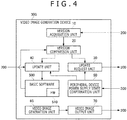
- FIG. 4 is a configuration diagram of the video image generation device 300.
- the drawing shows primarily the functional configuration of the video image generation device 300 for updating the basic software and the firmware.
- the functional configuration of the video image relay device 200 is implemented by hardware, by software, or by a combination of both.
- a version acquisition unit 10 receives from the video image relay device 200 information about the version of the firmware 520 installed in the video image relay device 200.
- the video image relay device 200 is connected with the video image generation device 300 using a cable 230 such as a USB interface cable and when the video image relay device 200 is turned on, the information about the version of the firmware 520 is conveyed from the video image relay device 200 to the video image generation device 300 via the cable 230.
- a version comparison unit 20 receives from the version acquisition unit 10 the information about the version of the firmware 520 in the video image relay device 200.
- the version comparison unit 20 also acquires information about the version of the firmware requested by the basic software 500 installed in the video image generation device 300.
- the information about the version of the firmware requested by the basic software 500 installed in the video image generation device 300 is written in a predetermined region of the basic software 500. The information may be read from that region.
- the firmware 510 itself of the version requested by the basic software 500 installed in the video image generation device 300 is included in the basic software 500.
- Information about the version of the firmware 510 included in the basic software 500 may be read as the information about the version of the firmware requested by the basic software 500.
- the version comparison unit 20 compares the version of the firmware 520 installed in the video image relay device 200 with the version of the firmware requested by the basic software 500 installed in the video image generation device 300. If the version of the firmware 520 installed in the video image relay device 200 is older than the version of the firmware requested by the basic software 500 installed in the video image generation device 300, the version comparison unit 20 notifies an update request unit 30 of the need to update the firmware of the video image relay device 200.
- the update request unit 30 supplies the video image relay device 200 with the firmware 510 included in the basic software 500 of the video image relay device 200 in order to update accordingly the firmware 520 installed in the video image relay device 200.
- a peripheral device power supply state confirmation unit 50 receives from the video image relay device 200 information about a power supply on/off state of the head-mounted display device 100, which is a typical peripheral device connected to the video image relay device 200. The peripheral device power supply state confirmation unit 50 then performs control so as not to let the update request unit 30 update the firmware 520 of the video image relay device 200 until the head-mounted display device 100 is turned on.
- the version acquisition unit 10 further acquires from the video image relay device 200 the information about the version of the basic software requested by the firmware 520 installed in the video image relay device 200.
- the version acquisition unit 10 transfers the acquired information to the version comparison unit 20.
- the version comparison unit 20 further compares the version of the basic software requested by the firmware 520 installed in the video image relay device 200 with the version of the basic software 500 installed in the video image generation device 300. If the version of the basic software 500 installed in the video image generation device 300 is older than the version of the basic software requested by the firmware 520 installed in the video image relay device 200, the version comparison unit 20 notifies an update unit 40 of the need to update the basic software 500 of the video image generation device 300.
- the update unit 40 downloads the basic software of the latest version from the server 700 via the network 600 and updates the basic software 500 of the video image generation device 300 to the latest version.
- the peripheral device power supply state confirmation unit 50 performs control so as not to let the update unit 40 update the basic software 500 of the video image generation device 300 until the head-mounted display device 100 is turned on.
- a video image generation unit 60 generates video images of games or applications and transfers the generated video images to a video image output unit 70.
- the video image output unit 70 transmits the video image data to the video image relay device 200 via the HDMI interface connection cable 210.
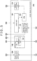
- FIG. 5 is a configuration diagram of the video image relay device 200.
- the functional configuration of the video image relay device 200 is implemented by hardware, by software, or by a combination of both.
- a version notification unit 110 acquires the information about the version of the firmware 520 installed in the video image relay device 200 and notifies the video image generation device 300 of the acquired information.
- an update unit 120 receives from the video image generation device 300 the firmware 510 included in the basic software 500 and updates accordingly the firmware 520 installed in the video image relay device 200.
- a peripheral device power supply state confirmation unit 130 acquires the information about the power supply on/off state of the head-mounted display device 100 from the head-mounted display device 100, which is a typical peripheral device connected to the video image relay device 200. Using the acquired information, the peripheral device power supply state confirmation unit 130 performs control so as not to let the update unit 120 update the firmware 520 of the video image relay device 200 until the head-mounted display device 100 is turned on.
- the peripheral device power supply state confirmation unit 130 transmits to the video image generation device 300 the information about the power supply on/off state of the head-mounted display device 100.
- the version notification unit 110 further notifies the video image generation device 300 of the information about the version of the basic software requested by the firmware 520 installed in the video image relay device 200.
- the information about the version of the basic software requested by the firmware 520 is written in a predetermined region of the firmware 520. The information may be read from that region.
- the video image generation device 300 updates its basic software 500 via the network.
- a distribution unit 140 receives video images from the video image generation device 300 and transmits the received video images to the display device 400 via the HDMI interface connection cable 220.
- the distribution unit 140 includes a conversion unit 142 that converts the video images received from the video image generation device 300 into a format ready for display on the head-mounted display device 100.
- the head-mounted display device 100 adopts optical lenses of large curvatures to provide the user with video images of a large viewing angle in front of and around the user in an arrangement allowing the user to look into a display panel through the lenses.
- the distortion aberration of the lenses of large curvatures distorts video images viewed through the lenses. This problem is bypassed by having images corrected beforehand so that they will appear normally when viewed through the lenses of large curvatures.
- the images thus corrected are displayed on the display panel of the head-mounted display device 100. This allows the user to view the images correctly when looking at the display panel through the lenses of large curvatures.
- the conversion unit 142 takes the video images generated by the video image generation device 300 for the ordinary display device 400 and converts the video images by taking into consideration the above-mentioned lens distortion of the head-mounted display device 100, before transmitting the video images to the head-mounted display device 100.
- a control signal processing unit 150 receives signals for controlling the head-mounted display device 100 from the video image generation device 300 and transmits the signals to the head-mounted display device 100.
- the control signal processing unit 150 further receives data such as attitude information from the head-mounted display device 100 and transmits the data to the video image generation device 300.
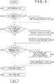
- FIG. 6 is a flowchart showing the steps of updating the basic software and the firmware in the video image system of the present embodiment.
- the user turns on the head-mounted display device 100, which is a peripheral device (S10). If the video image generation device 300 is not started yet (N in S12), the video image generation device 300 is started (S14). If the video image generation device 300 is already started (Y in S12), and if the version of the basic software installed in the video image generation device 300 is older than the version of the basic software requested by the firmware installed in the video image relay device 200 (Y in S16), the basic software of the latest version is downloaded via the network, and the basic software of the video image generation device 300 is updated accordingly (S18). The video image generation device 300 is then restarted (S20).
- the firmware 520 installed in the video image relay device 200 is updated using the firmware 510 included in the basic software 500 (S24).
- the video image relay device 200 is then restarted (S26).
- the firmware 520 of the video image relay device 200 may be updated manually for the purpose of fixing bugs.
- the firmware is downloaded directly from the server via the network for the update without waiting for the basic software 500 of the video image generation device 300 to be updated.
- a recovery menu may be used to reinstall the firmware 520 of the video image relay device 200.
- the firmware 520 of the video image relay device 200 is updated using the firmware 510 included in the basic software 500.
- the firmware 520 of the video image relay device 200 is not updated until the head-mounted display device 100 is turned on. This makes it possible to avoid situations such as one in which the user must wait for the home screen to appear until the firmware 520 of the video image relay device 200 is updated despite the head-mounted display device 100 not being used.
- the firmware 510 included in the basic software 500 of the video image generation device 300 is used to update the firmware 520 of the video image relay device 200, the firmware 520 of the video image relay device 200 is rapidly updated. There is no need for the video image generation device 300 to be connected with the network in order to download the firmware of the latest version.
- the version of the basic software 500 in the video image generation device 300 is older than the version of the basic software requested by the firmware 520 of the video image relay device 200, the basic software 500 of the video image generation device 300 is updated to the latest version via the network.
- the basic software 500 of the video image generation device 300 is not updated until the head-mounted display device 100 is turned on. This also makes it possible to avoid the situation in which the user must wait for the basic software 500 of the video image generation device 300 to be updated despite the head-mounted display device 100 not being used.
- the basic software 500 of the video image generation device 300 and the firmware 520 of the video image relay device 200 are guaranteed to be the mutually requested versions.
- the relationship between the version of the basic software and the version of the firmware is prescribed in such a manner that they are automatically updated to the mutually requested versions.
- the head-mounted display device 100 itself has firmware installed therein.
- the firmware of the head-mounted display device 100 is included in the firmware of the video image relay device 200 and is supplied to the head-mounted display device 100 from the video image relay device 200.
- the firmware of the head-mounted display device 100 may be arranged to be updated simultaneously.
- the video image generation device 300 and the video image relay device 200 may be integrated to form an "integrated video image generation device.”
- the head-mounted display device 100 is directly connected to the integrated video image generation device.
- the firmware update method discussed above in connection with the embodiment may be applied to updating the firmware of the head-mounted display device 100.
- the firmware of the head-mounted display device 100 is updated using the firmware included in the basic software of the integrated video image generation device.
- the head-mounted display device 100 was described above as a typical peripheral device in connection with the embodiment.
- any peripheral device other than the head-mounted display device 100 may be used.
- the firmware update method of the above-described embodiment may also be applied to updating the firmware of such peripheral devices.
- the techniques of the present invention may be used to update basic software or firmware in an information processing system with which peripheral devices are connected.
Landscapes
- Engineering & Computer Science (AREA)
- Theoretical Computer Science (AREA)
- General Engineering & Computer Science (AREA)
- Physics & Mathematics (AREA)
- General Physics & Mathematics (AREA)
- Software Systems (AREA)
- Computer Security & Cryptography (AREA)
- Quality & Reliability (AREA)
- Stored Programmes (AREA)
- Information Transfer Between Computers (AREA)
Abstract
Description
- The present invention relates to techniques for updating basic software or firmware in an information processing system with which peripheral devices are connected.
- There have been developed video image systems having a video image generation device such as a game machine or a personal computer connected with a head-mounted display device that presents its user with video images on a display panel in front of the user's eyes to enhance realistic sensation. Peripheral devices such as the head-mounted display device are operated using dedicated firmware.
- The firmware of a peripheral device needs to be updated independently of the basic software of the video image generation device with which the peripheral device is connected. However, the user may find it inconvenient if time is spent on updating the firmware of the peripheral device every time the video image generation device is started even though the peripheral device is not used.
- The present invention has been made in view of the above circumstances. An object of the invention is to provide techniques for efficiently updating basic software or firmware in an information processing system with which peripheral devices are connected.
- In solving the above problem and according to one embodiment of the present invention, there is provided an information processing device connected with a peripheral device via a relay device. The information processing device includes a version acquisition unit configured to acquire from the relay device information related to version of firmware installed in the relay device, a version comparison unit configured to compare the version of the firmware installed in the relay device with version of firmware requested by basic software installed in the information processing device, and an update request unit configured such that if the version of the firmware installed in the relay device is older than the version of the firmware requested by the basic software installed in the information processing device, the update request unit supplies the relay device with firmware for the relay device included in the basic software in order to update accordingly the firmware installed in the relay device.
- According to another embodiment of the present invention, there is provided a relay device connecting a peripheral device to an information processing device. The relay device includes a version notification unit configured to acquire information related to version of firmware installed in the relay device and notify the information processing device of the information, and an update unit configured such that if the version of the firmware installed in the relay device is older than version of firmware requested by basic software installed in the information processing device, the update unit receives from the information processing device firmware for the relay device included in the basic software in order to update accordingly the firmware installed in the relay device.
- According to a further embodiment of the present invention, there is provided an information processing system including an information processing device and a relay device connecting a peripheral device to the information processing device. The information processing device includes a version acquisition unit configured to acquire from the relay device information related to version of firmware installed in the relay device, a version comparison unit configured to compare the version of the firmware installed in the relay device with version of firmware requested by basic software installed in the information processing device, and an update request unit configured such that if the version of the firmware installed in the relay device is older than the version of the firmware requested by the basic software installed in the information processing device, the update request unit supplies the relay device with firmware for the relay device included in the basic software in order to update accordingly the firmware installed in the relay device. The relay device includes a version notification unit configured to acquire the information related to the version of the firmware installed in the relay device and notify the information processing device of the information, and an update unit configured such that if the version of the firmware installed in the relay device is older than the version of the firmware requested by the basic software installed in the information processing device, the update unit receives from the information processing device the firmware for the relay device included in the basic software in order to update accordingly the firmware installed in the relay device.
- According to a further embodiment of the present invention, there is provided a software update method updating firmware of a relay device or basic software of an information processing device, the relay device and the information processing device being included in an information processing system, the relay device being used to connect a peripheral device to the information processing device. The software update method includes a version acquisition step of acquiring from the relay device information related to version of firmware installed in the relay device, a version comparison step of comparing the version of the firmware installed in the relay device with version of firmware requested by the basic software installed in the information processing device, and an update request step of, if the version of the firmware installed in the relay device is older than the version of the firmware requested by the basic software installed in the information processing device, supplying the relay device with firmware for the relay device included in the basic software in order to update accordingly the firmware installed in the relay device.
- Incidentally, if other combinations of the above-outlined composing elements or the above expressions of the present invention are converted between different forms such as a method, a device, a system, a computer program, a data structure, and a recording medium, they still constitute effective embodiments of the present invention.
- According to the present invention, basic software or firmware in an information processing system with which peripheral devices are connected is updated efficiently.
-
- [
FIG. 1 ]
FIG. 1 is a configuration diagram of a video image system as one embodiment. - [
FIG. 2A ]
FIG. 2A is an explanatory view showing a step of updating firmware of a video image relay device included inFIG. 1 . - [
FIG. 2B ]
FIG. 2B is an explanatory view showing another step of updating the firmware of the video image relay device inFIG. 1 . - [
FIG. 2C ]
FIG. 2C is an explanatory view showing another step of updating the firmware of the video image relay device inFIG. 1 . - [
FIG. 3A ]
FIG. 3A is an explanatory view showing a step of updating basic software of a video image generation device included inFIG. 1 . - [
FIG. 3B ]
FIG. 3B is an explanatory view showing another step of updating the basic software of the video image generation device inFIG. 1 . - [
FIG. 3C ]
FIG. 3C is an explanatory view showing another step of updating the basic software of the video image generation device inFIG. 1 . - [
FIG. 4 ]
FIG. 4 is a configuration diagram of the video image generation device inFIG. 1 . - [
FIG. 5 ]
FIG. 5 is a configuration diagram of the video image relay device inFIG. 1 . - [
FIG. 6 ]
FIG. 6 is a flowchart showing the steps of updating the basic software and the firmware in the video image system inFIG. 1 . -
FIG. 1 is a configuration diagram of a video image system as one embodiment. - A video
image generation device 300 is a typical information processing device according to the present application. More specifically, the videoimage generation device 300 is a game machine or a personal computer, for example, which generates video images by computer graphics. Although not shown, the videoimage generation device 300 may connect and communicate with networks to receive data from servers or to transmit data to other terminals. - A
camera 310 may be connected to the videoimage generation device 300 using aconnection cable 240. Awireless controller 320 and amotion controller 330 may also be connected wirelessly to the videoimage generation device 300. - A video
image relay device 200 is connected to the videoimage generation device 300 via an interface such as a universal serial bus (USB) using aconnection cable 230. A head-mounteddisplay device 100 is connected to the videoimage relay device 200 using adedicated cable 260. The head-mounteddisplay device 100 is a typical peripheral device associated with the present application. - A high-definition multimedia interface (HDMI; registered trademark) output terminal of the video
image generation device 300 is connected with an HDMI input terminal of the videoimage relay device 200 via aconnection cable 210. An HDMI output terminal of the videoimage relay device 200 is connected with an HDMI input terminal of adisplay device 400 via aconnection cable 220. - The video
image relay device 200 is connected to a power source via apower cable 250. It is assumed here that the videoimage relay device 200 is always turned on. Obviously, if the head-mounteddisplay device 100 acting as a peripheral device is not used, the videoimage relay device 200 may be turned off. - The video
image relay device 200 relays video images output from the videoimage generation device 300 to thedisplay device 400 and to the head-mounteddisplay device 100. The video images generated by the videoimage generation device 300 are output through the HDMI output terminal of the videoimage generation device 300 and input to the HDMI input terminal of the videoimage relay device 200 via theconnection cable 210. - The video images input to the HDMI input terminal of the video
image relay device 200 are output unmodified from the HDMI output terminal of the videoimage relay device 200. From there, the video images are input to the HDMI input terminal of thedisplay device 400 via theconnection cable 220. At the same time, the video images input to the HDMI input terminal of the videoimage relay device 200 are converted to an image format suitable for the head-mounteddisplay device 100, before being input to the head-mounteddisplay device 100 via thededicated cable 260. - That is, the video
image relay device 200 relays the video images unmodified from the videoimage generation device 300 to thedisplay device 400. At the same time, the videoimage relay device 200 converts the video images coming from the videoimage generation device 300 into a format suitable for the head-mounteddisplay device 100 before relaying the video images to the head-mounteddisplay device 100. This allows the user wearing the head-mounteddisplay device 100 to view the video images in front of his or her eyes, while enabling other users to view the video images conventionally on thedisplay device 400. The videoimage relay device 200 thus functions as a converter-distributer that may convert as needed the video images coming from the videoimage generation device 300 before distributing them to multiple display devices. - The basic software for executing the commands of applications such as games is installed in the video
image generation device 300. The firmware for the head-mounteddisplay device 100 is installed in the videoimage relay device 200. The basic software and the firmware need to be updated as needed. The data necessary for updating the basic software and the firmware is either read from a recording medium inserted in the videoimage generation device 300 and written to a storage area of the videoimage generation device 300, or downloaded from servers over networks into the storage area of the videoimage generation device 300. -
FIGS. 2A to 2C are explanatory views showing steps of updating the firmware of the videoimage relay device 200. -
Basic software 500 installed in the videoimage generation device 300 includesfirmware 510 to be installed in the videoimage relay device 200 for use by the head-mounteddisplay device 100. This is a configuration similar to one in which the operating system of a computer includes the drivers of various peripheral devices. The driver for a peripheral device included in the operating system is read and installed into the computer when that peripheral device is configured for use. In like manner, thefirmware 510 for the head-mounteddisplay device 100 included in thebasic software 500 is installed into the videoimage relay device 200 before the head-mounteddisplay device 100 is used. - As shown in
FIG. 2A , thebasic software 500 of version 3.00 is initially installed in the videoimage generation device 300. Thebasic software 500 of version 3.00 includes thefirmware 510 of version 1.00.Firmware 520 of version 1.00 is installed in the videoimage relay device 200. The head-mounteddisplay device 100 is turned off. - A
recording medium 530 storing applications such as games is inserted in the videoimage generation device 300. Therecording medium 530 stores the basic software of the latest version along with the applications. In this case, therecording medium 530 storesbasic software 502 of version 4.00 that includesfirmware 512 of version 2.00. Thefirmware 512 of version 2.00 is the firmware of the latest version of which the performance is confirmed by thebasic software 502 of version 4.00. - As shown in
FIG. 2B , when therecording medium 530 is inserted, the videoimage generation device 300 compares the version of the basic software stored on therecording medium 530 with the version of the basic software already installed in the videoimage generation device 300. If the version of the basic software on therecording medium 530 is newer than the version of the basic software already installed in the videoimage generation device 300, the videoimage generation device 300 reads thebasic software 502 of the latest version 4.00 from therecording medium 530 and updates the currently installed basic software accordingly. Thebasic software 502 stored on therecording medium 530 includes thefirmware 512 of the latest version 2.00. Thus the update brings thebasic software 500 of the videoimage generation device 300 to version 4.00 and thefirmware 510 included in thebasic software 500 to version 2.00. - At the time of updating the
basic software 500 of the videoimage generation device 300 inFIG. 2B , the head-mounteddisplay device 100 is turned off. At this point, thefirmware 520 of the videoimage relay device 200 has yet to be updated; thefirmware 520 of the old version 1.00 remains unchanged. - As shown in
FIG. 2C , when the head-mounteddisplay device 100 is turned on, the videoimage generation device 300 is notified of information about the version of thefirmware 520 already installed in the videoimage relay device 200. The videoimage generation device 300 compares the version of thefirmware 520 currently installed in the videoimage relay device 200 with the version of the firmware requested by thebasic software 500 of the videoimage generation device 300. If the version of thefirmware 520 in the videoimage relay device 200 is older than the version requested by thebasic software 500 of the videomage generation device 300, thefirmware 510 of the latest version included in thebasic software 500 is supplied to the videoimage relay device 200 in order to update the firmware of the videoimage relay device 200. - In this case, a predetermined region of the
basic software 500 prescribes that the version of the firmware requested by thebasic software 500 of the videoimage generation device 300 be version 2.00 or higher. The version of thefirmware 520 currently installed in the videoimage relay device 200 is version 1.00, which is older than version 2.00. Thus thefirmware 510 of the latest version 2.00 included in thebasic software 500 is supplied to the videoimage relay device 200 to bring thefirmware 520 of the videoimage relay device 200 to version 2.00. - As described above with reference to
FIGS. 2A to 2C , even when thebasic software 500 of the videoimage generation device 300 is updated together with thefirmware 510 included in thebasic software 500, thefirmware 520 of the videoimage relay device 200 is not updated until the head-mounteddisplay device 100 is turned on. Only when the head-mounteddisplay device 100 is turned on, is thefirmware 520 of the videoimage relay device 200 updated with thefirmware 510 of the latest version included in thebasic software 500 of the latest version in the videoimage generation device 300. - The user may find it inconvenient if it is necessary to wait for the
firmware 520 of the videoimage relay device 200 to be updated despite the user not using the head-mounteddisplay device 100. According to the firmware update method of the present embodiment, when the head-mounteddisplay device 100 is turned on, i.e., at the time the head-mounteddisplay device 100 is used, thefirmware 520 of the videoimage relay device 200 is updated as needed. This method offers the advantage of not giving the user unnecessary frustration at the time of updating the firmware. -
FIGS. 3A to 3C are explanatory views showing steps of updating the basic software of the videoimage generation device 300. - As shown in
FIG. 3A , a videoimage generation device 300A of user A is connected with a videoimage relay device 200A that in turn is connected with a head-mounteddisplay device 100A.Basic software 500A of version 4.00 is installed in the videoimage generation device 300A. Thebasic software 500A includesfirmware 510A of version 2.00.Firmware 520A of version 2.00 is installed in the videoimage relay device 200A. - User A disconnects the video
image relay device 200A and the head-mounteddisplay device 100A from the videoimage generation device 300A, and connects the disconnected devices to a videoimage generation device 300B of user B. The situation assumed here may be one in which user B is a friend of user A's and user A brings his or her videoimage relay device 200A and the head-mounteddisplay device 100A from his or her place to user B's place.Basic software 500B of version 3.00 is installed in the videoimage generation device 300B of user B. Thebasic software 500B includesfirmware 510B of version 1.00. - As shown in
FIG. 3B , the videoimage generation device 300B of user B is connected with the videoimage relay device 200A and the head-mounteddisplay device 100A of user A. At this point, the version of thefirmware 520A installed in the videoimage relay device 200A of user A is version 2.00, whereas the version of thebasic software 500B installed in the videoimage generation device 300B is version 3.00. Thebasic software 500B of version 3.00 installed in the videoimage generation device 300B supports the firmware of version 1.00 but does not comply with thefirmware 520A of the new version 2.00. - When the head-mounted
display device 100A is turned on, the videoimage relay device 200A notifies the videoimage generation device 300B of information about the version of the basic software requested by thefirmware 520A of version 2.00 installed in the videoimage relay device 200A. In this case, a predetermined region of the firmware prescribes that the firmware of version 2.00 request the basic software of version 4.00 or higher. This information is conveyed to the videoimage generation device 300B. - As shown
FIG. 3C , the videoimage generation device 300B compares the version of the basic software conveyed from the videoimage relay device 200A and requested by thefirmware 520A of the videoimage relay device 200A with the version of thebasic software 500B in the videoimage generation device 300B. If the version of thebasic software 500B is older than the version conveyed from the videoimage relay device 200A, the videoimage generation device 300B downloads thebasic software 500B of a new version from aserver 700 via anetwork 600 and installs the downloaded basic software. - In this case, the version of the basic software requested by the
firmware 520A of the videoimage relay device 200A is version 4.00 or higher, whereas the version of thebasic software 500B in the videoimage generation device 300B is version 3.00, which is older than version 4.00. Thus the basic software of the latest version 4.00 is downloaded from theserver 700 and installed into the videoimage generation device 300B. - As a result of this, the
basic software 500B of the videoimage generation device 300B is replaced with the basic software of version 4.00 requested by thefirmware 520A of version 2.00 in the videoimage relay device 200A. The basic software thus comes to support thefirmware 520A of version 2.00 in the videoimage relay device 200A. -
FIG. 4 is a configuration diagram of the videoimage generation device 300. The drawing shows primarily the functional configuration of the videoimage generation device 300 for updating the basic software and the firmware. The functional configuration of the videoimage relay device 200 is implemented by hardware, by software, or by a combination of both. - A
version acquisition unit 10 receives from the videoimage relay device 200 information about the version of thefirmware 520 installed in the videoimage relay device 200. When the videoimage relay device 200 is connected with the videoimage generation device 300 using acable 230 such as a USB interface cable and when the videoimage relay device 200 is turned on, the information about the version of thefirmware 520 is conveyed from the videoimage relay device 200 to the videoimage generation device 300 via thecable 230. - A
version comparison unit 20 receives from theversion acquisition unit 10 the information about the version of thefirmware 520 in the videoimage relay device 200. Theversion comparison unit 20 also acquires information about the version of the firmware requested by thebasic software 500 installed in the videoimage generation device 300. - The information about the version of the firmware requested by the
basic software 500 installed in the videoimage generation device 300 is written in a predetermined region of thebasic software 500. The information may be read from that region. Thefirmware 510 itself of the version requested by thebasic software 500 installed in the videoimage generation device 300 is included in thebasic software 500. Information about the version of thefirmware 510 included in thebasic software 500 may be read as the information about the version of the firmware requested by thebasic software 500. - Next, the
version comparison unit 20 compares the version of thefirmware 520 installed in the videoimage relay device 200 with the version of the firmware requested by thebasic software 500 installed in the videoimage generation device 300. If the version of thefirmware 520 installed in the videoimage relay device 200 is older than the version of the firmware requested by thebasic software 500 installed in the videoimage generation device 300, theversion comparison unit 20 notifies anupdate request unit 30 of the need to update the firmware of the videoimage relay device 200. - Given the notification of the need for the update from the
version comparison unit 20, theupdate request unit 30 supplies the videoimage relay device 200 with thefirmware 510 included in thebasic software 500 of the videoimage relay device 200 in order to update accordingly thefirmware 520 installed in the videoimage relay device 200. - A peripheral device power supply
state confirmation unit 50 receives from the videoimage relay device 200 information about a power supply on/off state of the head-mounteddisplay device 100, which is a typical peripheral device connected to the videoimage relay device 200. The peripheral device power supplystate confirmation unit 50 then performs control so as not to let theupdate request unit 30 update thefirmware 520 of the videoimage relay device 200 until the head-mounteddisplay device 100 is turned on. - The
version acquisition unit 10 further acquires from the videoimage relay device 200 the information about the version of the basic software requested by thefirmware 520 installed in the videoimage relay device 200. Theversion acquisition unit 10 transfers the acquired information to theversion comparison unit 20. - The
version comparison unit 20 further compares the version of the basic software requested by thefirmware 520 installed in the videoimage relay device 200 with the version of thebasic software 500 installed in the videoimage generation device 300. If the version of thebasic software 500 installed in the videoimage generation device 300 is older than the version of the basic software requested by thefirmware 520 installed in the videoimage relay device 200, theversion comparison unit 20 notifies anupdate unit 40 of the need to update thebasic software 500 of the videoimage generation device 300. - Given the notification of the need for the update from the
version comparison unit 20, theupdate unit 40 downloads the basic software of the latest version from theserver 700 via thenetwork 600 and updates thebasic software 500 of the videoimage generation device 300 to the latest version. - The peripheral device power supply
state confirmation unit 50 performs control so as not to let theupdate unit 40 update thebasic software 500 of the videoimage generation device 300 until the head-mounteddisplay device 100 is turned on. - A video
image generation unit 60 generates video images of games or applications and transfers the generated video images to a videoimage output unit 70. The videoimage output unit 70 transmits the video image data to the videoimage relay device 200 via the HDMIinterface connection cable 210. -
FIG. 5 is a configuration diagram of the videoimage relay device 200. The functional configuration of the videoimage relay device 200 is implemented by hardware, by software, or by a combination of both. - A
version notification unit 110 acquires the information about the version of thefirmware 520 installed in the videoimage relay device 200 and notifies the videoimage generation device 300 of the acquired information. - If the version of the
firmware 520 installed in the videoimage relay device 200 is older than the version of the firmware requested by thebasic software 500 installed in the videoimage generation device 300, anupdate unit 120 receives from the videoimage generation device 300 thefirmware 510 included in thebasic software 500 and updates accordingly thefirmware 520 installed in the videoimage relay device 200. - A peripheral device power supply
state confirmation unit 130 acquires the information about the power supply on/off state of the head-mounteddisplay device 100 from the head-mounteddisplay device 100, which is a typical peripheral device connected to the videoimage relay device 200. Using the acquired information, the peripheral device power supplystate confirmation unit 130 performs control so as not to let theupdate unit 120 update thefirmware 520 of the videoimage relay device 200 until the head-mounteddisplay device 100 is turned on. - Also, the peripheral device power supply
state confirmation unit 130 transmits to the videoimage generation device 300 the information about the power supply on/off state of the head-mounteddisplay device 100. - The
version notification unit 110 further notifies the videoimage generation device 300 of the information about the version of the basic software requested by thefirmware 520 installed in the videoimage relay device 200. The information about the version of the basic software requested by thefirmware 520 is written in a predetermined region of thefirmware 520. The information may be read from that region. As described above, if the version of thebasic software 500 installed in the videoimage generation device 300 is older than the version of the basic software requested by thefirmware 520 installed in the videoimage relay device 200 according to the version information conveyed from theversion acquisition unit 10 in the videoimage relay device 200, the videoimage generation device 300 updates itsbasic software 500 via the network. - A
distribution unit 140 receives video images from the videoimage generation device 300 and transmits the received video images to thedisplay device 400 via the HDMIinterface connection cable 220. Thedistribution unit 140 includes aconversion unit 142 that converts the video images received from the videoimage generation device 300 into a format ready for display on the head-mounteddisplay device 100. - The head-mounted
display device 100 adopts optical lenses of large curvatures to provide the user with video images of a large viewing angle in front of and around the user in an arrangement allowing the user to look into a display panel through the lenses. The distortion aberration of the lenses of large curvatures distorts video images viewed through the lenses. This problem is bypassed by having images corrected beforehand so that they will appear normally when viewed through the lenses of large curvatures. The images thus corrected are displayed on the display panel of the head-mounteddisplay device 100. This allows the user to view the images correctly when looking at the display panel through the lenses of large curvatures. - The
conversion unit 142 takes the video images generated by the videoimage generation device 300 for theordinary display device 400 and converts the video images by taking into consideration the above-mentioned lens distortion of the head-mounteddisplay device 100, before transmitting the video images to the head-mounteddisplay device 100. - A control
signal processing unit 150 receives signals for controlling the head-mounteddisplay device 100 from the videoimage generation device 300 and transmits the signals to the head-mounteddisplay device 100. The controlsignal processing unit 150 further receives data such as attitude information from the head-mounteddisplay device 100 and transmits the data to the videoimage generation device 300. -
FIG. 6 is a flowchart showing the steps of updating the basic software and the firmware in the video image system of the present embodiment. - The user turns on the head-mounted
display device 100, which is a peripheral device (S10). If the videoimage generation device 300 is not started yet (N in S12), the videoimage generation device 300 is started (S14). If the videoimage generation device 300 is already started (Y in S12), and if the version of the basic software installed in the videoimage generation device 300 is older than the version of the basic software requested by the firmware installed in the video image relay device 200 (Y in S16), the basic software of the latest version is downloaded via the network, and the basic software of the videoimage generation device 300 is updated accordingly (S18). The videoimage generation device 300 is then restarted (S20). - Next, if the version of the firmware installed in the video
image relay device 200 is older than the version of the firmware requested by the basic software installed in the video image generation device 300 (Y in S22), thefirmware 520 installed in the videoimage relay device 200 is updated using thefirmware 510 included in the basic software 500 (S24). The videoimage relay device 200 is then restarted (S26). - When the update necessary for the
basic software 500 of the videoimage generation device 300 or for thefirmware 520 of the videoimage relay device 200 is completed, with the videoimage generation device 300 or the videoimage relay device 200 restarted following the update, user selection is performed on a login screen (S28). A home screen is then displayed (S30). - Although not discussed in connection with the above embodiment, the
firmware 520 of the videoimage relay device 200 may be updated manually for the purpose of fixing bugs. In such a case, the firmware is downloaded directly from the server via the network for the update without waiting for thebasic software 500 of the videoimage generation device 300 to be updated. In case of a failure such as faulty operation of the head-mounteddisplay device 100, a recovery menu may be used to reinstall thefirmware 520 of the videoimage relay device 200. - According to the software update method of the present embodiment described above, if the version of the
firmware 520 in the videoimage relay device 200 is older than the version of the firmware requested by thebasic software 500 of the videoimage generation device 300, thefirmware 520 of the videoimage relay device 200 is updated using thefirmware 510 included in thebasic software 500. - The
firmware 520 of the videoimage relay device 200 is not updated until the head-mounteddisplay device 100 is turned on. This makes it possible to avoid situations such as one in which the user must wait for the home screen to appear until thefirmware 520 of the videoimage relay device 200 is updated despite the head-mounteddisplay device 100 not being used. - Because the
firmware 510 included in thebasic software 500 of the videoimage generation device 300 is used to update thefirmware 520 of the videoimage relay device 200, thefirmware 520 of the videoimage relay device 200 is rapidly updated. There is no need for the videoimage generation device 300 to be connected with the network in order to download the firmware of the latest version. - If the version of the
basic software 500 in the videoimage generation device 300 is older than the version of the basic software requested by thefirmware 520 of the videoimage relay device 200, thebasic software 500 of the videoimage generation device 300 is updated to the latest version via the network. - In that case, too, the
basic software 500 of the videoimage generation device 300 is not updated until the head-mounteddisplay device 100 is turned on. This also makes it possible to avoid the situation in which the user must wait for thebasic software 500 of the videoimage generation device 300 to be updated despite the head-mounteddisplay device 100 not being used. - According to the present embodiment described above, at the time the head-mounted
display device 100 is used, thebasic software 500 of the videoimage generation device 300 and thefirmware 520 of the videoimage relay device 200 are guaranteed to be the mutually requested versions. The relationship between the version of the basic software and the version of the firmware is prescribed in such a manner that they are automatically updated to the mutually requested versions. This enables the peripheral devices such as the head-mounteddisplay device 100 to be always used in accordance with the basic software and the firmware of appropriate versions without having to designate the version of the firmware for the peripheral devices such as the head-mounteddisplay device 100 on the side of applications such as games. - While the present invention has been described in conjunction with a specific embodiment given as an example, it should be understood by those skilled in the art that the above-described composing elements and various processes may be combined in diverse ways and that such combinations, variations and modifications also fall within the scope of the present invention.
- Whereas the method of updating the firmware of the video
image relay device 200 was explained in connection with the above embodiment, the head-mounteddisplay device 100 itself has firmware installed therein. The firmware of the head-mounteddisplay device 100 is included in the firmware of the videoimage relay device 200 and is supplied to the head-mounteddisplay device 100 from the videoimage relay device 200. When the firmware of the videoimage relay device 200 is updated upon power-up of the head-mounteddisplay device 100, the firmware of the head-mounteddisplay device 100 may be arranged to be updated simultaneously. - If the functional configuration of the video
image relay device 200 is included in the videoimage generation device 300, the videoimage generation device 300 and the videoimage relay device 200 may be integrated to form an "integrated video image generation device." The head-mounteddisplay device 100 is directly connected to the integrated video image generation device. In such a case, the firmware update method discussed above in connection with the embodiment may be applied to updating the firmware of the head-mounteddisplay device 100. Upon power-up of the head-mounteddisplay device 100, the firmware of the head-mounteddisplay device 100 is updated using the firmware included in the basic software of the integrated video image generation device. - The head-mounted
display device 100 was described above as a typical peripheral device in connection with the embodiment. - Alternatively, any peripheral device other than the head-mounted
display device 100 may be used. The firmware update method of the above-described embodiment may also be applied to updating the firmware of such peripheral devices. - 10 Version acquisition unit, 20 Version comparison unit, 30 Update request unit, 40 Update unit, 50 Peripheral device power supply state confirmation unit, 60 Video image generation unit, 70 Video image output unit, 100 Head-mounted display device, 110 Version notification unit, 120 Update unit, 130 Peripheral device power supply state confirmation unit, 140 Distribution unit, 142 Conversion unit, 150 Control signal processing unit, 200 Video image relay device, 300 Video image generation device, 310 Camera, 320 Wireless controller, 330 Motion controller, 400 Display device, 500 Basic software, 510 Firmware, 520 Firmware, 530 Recording medium, 600 Network, 700 Server.
- The techniques of the present invention may be used to update basic software or firmware in an information processing system with which peripheral devices are connected.
Claims (12)
- An information processing device connected with a peripheral device via a relay device, the information processing device comprising:a version acquisition unit configured to acquire from the relay device information related to version of firmware installed in the relay device;a version comparison unit configured to compare the version of the firmware installed in the relay device with version of firmware requested by basic software installed in the information processing device; andan update request unit configured such that if the version of the firmware installed in the relay device is older than the version of the firmware requested by the basic software installed in the information processing device, the update request unit supplies the relay device with firmware for the relay device included in the basic software in order to update accordingly the firmware installed in the relay device.
- The information processing device according to claim 1,
wherein the update request unit prevents the firmware from being updated until the peripheral device is turned on. - The information processing device according to claim 1 or 2, the version acquisition unit further acquiring from the relay device information related to version of the basic software requested by the firmware installed in the relay device, the version comparison unit further comparing the version of the basic software requested by the firmware installed in the relay device with version of the basic software installed in the information processing device,
the information processing device further comprising an update unit configured such that if the version of the basic software installed in the information processing device is older than the version of the basic software requested by the firmware installed in the relay device, the update unit downloads the basic software of the latest version in order to update accordingly the basic software of the information processing device. - The information processing device according to claim 3,
wherein the update unit does not update the basic software until the peripheral device is turned on. - A relay device connecting a peripheral device to an information processing device, the relay device comprising:a version notification unit configured to acquire information related to version of firmware installed in the relay device and notify the information processing device of the information; andan update unit configured such that if the version of the firmware installed in the relay device is older than version of firmware requested by basic software installed in the information processing device, the update unit receives from the information processing device firmware for the relay device included in the basic software in order to update accordingly the firmware installed in the relay device.
- The relay device according to claim 5, wherein the update unit does not update the firmware until the peripheral device is turned on.
- The relay device according to claim 5 or 6, wherein the version notification unit further notifies the information processing device of information related to version of the basic software requested by the firmware installed in the relay device.
- The relay device according to any one of claims 5 to 7, further comprising:a distribution unit configured to convert and distribute as needed a video image generated by the information processing device,wherein the distribution unit converts the video image for display on a display device mounted on the peripheral device and distributes the converted video image to the peripheral device.
- An information processing system comprising:an information processing device; anda relay device connecting a peripheral device to the information processing device,wherein the information processing device includes a version acquisition unit configured to acquire from the relay device information related to version of firmware installed in the relay device,a version comparison unit configured to compare the version of the firmware installed in the relay device with version of firmware requested by basic software installed in the information processing device, andan update request unit configured such that if the version of the firmware installed in the relay device is older than the version of the firmware requested by the basic software installed in the information processing device, the update request unit supplies the relay device with firmware for the relay device included in the basic software in order to update accordingly the firmware installed in the relay device, andthe relay device includesa version notification unit configured to acquire the information related to the version of the firmware installed in the relay device and notify the information processing device of the information, andan update unit configured such that if the version of the firmware installed in the relay device is older than the version of the firmware requested by the basic software installed in the information processing device, the update unit receives from the information processing device the firmware for the relay device included in the basic software in order to update accordingly the firmware installed in the relay device.
- The information processing system according to claim 9,
wherein the version acquisition unit further acquires from the relay device information related to version of the basic software requested by the firmware installed in the relay device,
the version comparison unit further compares the version of the basic software requested by the firmware installed in the relay device with version of the basic software installed in the information processing device,
the information processing device further includes an update unit configured such that if the version of the basic software installed in the information processing device is older than the version of the basic software requested by the firmware installed in the relay device, the update unit downloads the basic software of the latest version in order to update accordingly the basic software of the information processing device, and
the version notification unit further notifies the information processing device of information related to the version of the basic software requested by the firmware installed in the relay device. - A software update method updating firmware of a relay device or basic software of an information processing device, the relay device and the information processing device being included in an information processing system, the relay device being used to connect a peripheral device to the information processing device, the software update method comprising:a version acquisition step of acquiring from the relay device information related to version of firmware installed in the relay device;a version comparison step of comparing the version of the firmware installed in the relay device with version of firmware requested by the basic software installed in the information processing deice; andan update request step of, if the version of the firmware installed in the relay device is older than the version of the firmware requested by the basic software installed in the information processing device, supplying the relay device with firmware for the relay device included in the basic software in order to update accordingly the firmware installed in the relay device.
- The software update method according to claim 11,
the version acquisition step further acquiring information related to version of the basic software requested by the firmware installed in the relay device,
the version comparison step comparing the version of the basic software requested by the firmware installed in the relay device with version of the basic software installed in the information processing device,
the software update method further comprising an update step of, if the version of the basic software installed in the information processing device is older than the version of the basic software requested by the firmware installed in the relay device, downloading the basic software of the latest version in order to update accordingly the basic software of the information processing device.
Applications Claiming Priority (2)
| Application Number | Priority Date | Filing Date | Title |
|---|---|---|---|
| JP2015080334A JP6433844B2 (en) | 2015-04-09 | 2015-04-09 | Information processing apparatus, relay apparatus, information processing system, and software update method |
| PCT/JP2016/061325 WO2016163429A1 (en) | 2015-04-09 | 2016-04-06 | Information processing device, relay device, information processing system, and software update method |
Publications (3)
| Publication Number | Publication Date |
|---|---|
| EP3282360A1 true EP3282360A1 (en) | 2018-02-14 |
| EP3282360A4 EP3282360A4 (en) | 2018-11-07 |
| EP3282360B1 EP3282360B1 (en) | 2022-08-24 |
Family
ID=57072313
Family Applications (1)
| Application Number | Title | Priority Date | Filing Date |
|---|---|---|---|
| EP16776595.7A Active EP3282360B1 (en) | 2015-04-09 | 2016-04-06 | Information processing device, relay device, information processing system, and software update method |
Country Status (6)
| Country | Link |
|---|---|
| US (1) | US10782957B2 (en) |
| EP (1) | EP3282360B1 (en) |
| JP (1) | JP6433844B2 (en) |
| KR (1) | KR102088318B1 (en) |
| CN (1) | CN107408067A (en) |
| WO (1) | WO2016163429A1 (en) |
Families Citing this family (7)
| Publication number | Priority date | Publication date | Assignee | Title |
|---|---|---|---|---|
| JP6414590B2 (en) * | 2014-03-14 | 2018-10-31 | オムロン株式会社 | Control device, control system, support device, and control device maintenance management method |
| JP6965034B2 (en) | 2017-06-19 | 2021-11-10 | 任天堂株式会社 | Information processing equipment, information processing system, information processing method, and information processing program |
| JP6859282B2 (en) | 2018-02-20 | 2021-04-14 | パナソニック株式会社 | Electronic devices, program update methods and computer programs |
| FR3083948A1 (en) * | 2018-07-16 | 2020-01-17 | STMicroelectronics (Grand Ouest) SAS | METHOD AND SYSTEM FOR MANAGING THE OPERATION OF A GROUP OF MULTIPLE CONNECTED OBJECTS |
| WO2020067619A1 (en) | 2018-09-27 | 2020-04-02 | 주식회사 엔도비전 | Hemostatic member for cervix, and hemostatic member kit for cervix |
| CN112348763B (en) * | 2020-11-09 | 2024-05-14 | 西安宇视信息科技有限公司 | Image enhancement method, device, electronic equipment and medium |
| CN113986278A (en) * | 2021-09-30 | 2022-01-28 | 云鲸智能(深圳)有限公司 | Firmware upgrading method, system, robot, base station and storage medium |
Family Cites Families (47)
| Publication number | Priority date | Publication date | Assignee | Title |
|---|---|---|---|---|
| US6075905A (en) * | 1996-07-17 | 2000-06-13 | Sarnoff Corporation | Method and apparatus for mosaic image construction |
| US6002426A (en) * | 1997-07-02 | 1999-12-14 | Cerprobe Corporation | Inverted alignment station and method for calibrating needles of probe card for probe testing of integrated circuits |
| US6360362B1 (en) | 1998-02-20 | 2002-03-19 | Intel Corporation | Automatic update of camera firmware |
| JP2000231060A (en) * | 1999-02-12 | 2000-08-22 | Olympus Optical Co Ltd | Image-formation optical system |
| US6728787B1 (en) * | 2000-03-31 | 2004-04-27 | Mitsubishi Electric Research Labs, Inc | System and method for locating and installing device drivers for peripheral devices |
| US7301655B1 (en) * | 2000-09-29 | 2007-11-27 | Marvell International Technology Ltd. | Printer formatter in a removable card |
| US6832373B2 (en) * | 2000-11-17 | 2004-12-14 | Bitfone Corporation | System and method for updating and distributing information |
| US7055148B2 (en) * | 2000-12-07 | 2006-05-30 | Hewlett-Packard Development Company, L.P. | System and method for updating firmware |
| JP2002278906A (en) * | 2001-03-21 | 2002-09-27 | Nec Corp | Update managing system, update client device, update server device and program |
| US20020188934A1 (en) * | 2001-06-12 | 2002-12-12 | Nortel Networks Limited | Method and system for upgrading existing firmware on third party hardware |
| CA2369228A1 (en) * | 2002-01-24 | 2003-07-24 | Alcatel Canada Inc. | System and method for managing configurable elements of devices in a network element and a network |
| JP4391781B2 (en) | 2003-08-29 | 2009-12-24 | オリンパス株式会社 | Data rewriting device and data rewriting method |
| WO2005045671A1 (en) * | 2003-10-27 | 2005-05-19 | American Power Conversion Corporation | System and method for updating a software program |
| US20060143600A1 (en) * | 2004-12-29 | 2006-06-29 | Andrew Cottrell | Secure firmware update |
| KR100794800B1 (en) * | 2005-12-12 | 2008-01-15 | 삼성전자주식회사 | Software update method and device |
| US20070261046A1 (en) * | 2006-05-04 | 2007-11-08 | Syntax Brillian Corp. | Television and display device with a USB port for updating firmware |
| US7770165B2 (en) * | 2006-08-25 | 2010-08-03 | Microsoft Corporation | Providing firmware updates to portable media devices |
| US7595933B2 (en) * | 2006-10-13 | 2009-09-29 | Apple Inc. | Head mounted display system |
| US8594180B2 (en) | 2007-02-21 | 2013-11-26 | Qualcomm Incorporated | 3D video encoding |
| JP4956247B2 (en) * | 2007-03-23 | 2012-06-20 | キヤノン株式会社 | Information processing apparatus and driver control method |
| JP5024668B2 (en) * | 2007-07-10 | 2012-09-12 | 富士ゼロックス株式会社 | Image forming apparatus and information processing apparatus |
| JP5127490B2 (en) * | 2008-02-07 | 2013-01-23 | キヤノン株式会社 | Image forming apparatus, remote update verification method and program for image forming apparatus |
| RU2011149630A (en) | 2009-06-05 | 2013-07-20 | Шарп Кабусики Кайся | SOFTWARE UPDATE SYSTEM, ELECTRONIC DEVICES AND METHOD OF UPDATING THE SOFTWARE |
| US8966101B2 (en) * | 2009-08-10 | 2015-02-24 | Sling Media Pvt Ltd | Systems and methods for updating firmware over a network |
| KR20110107579A (en) * | 2010-03-25 | 2011-10-04 | 삼성전자주식회사 | Print Control Terminal and Firmware Upgrade Method |
| US9727124B2 (en) * | 2011-04-19 | 2017-08-08 | Apple Inc. | Power saving application update in a portable electronic device |
| JP5453344B2 (en) * | 2011-05-10 | 2014-03-26 | 三菱電機株式会社 | Communication adapter, controller and network system |
| JP5790222B2 (en) * | 2011-07-12 | 2015-10-07 | 株式会社リコー | Communication device, update method, and update program |
| CA3048647C (en) * | 2011-10-28 | 2022-08-16 | Magic Leap, Inc. | System and method for augmented and virtual reality |
| JP2013130923A (en) * | 2011-12-20 | 2013-07-04 | Canon Inc | Image processor, server device, information processing method, and program |
| KR20130078675A (en) * | 2011-12-30 | 2013-07-10 | 삼성전자주식회사 | Display apparatus, upgrading apparatus, display system and control method of the same |
| TW201332337A (en) * | 2012-01-17 | 2013-08-01 | Da2 Technologies Corp | Smart 3D video HDMI distributor |
| KR101357951B1 (en) * | 2012-03-02 | 2014-02-04 | 엘에스산전 주식회사 | Method for maintaining firmware of digital protective relay and the digital protective relay performing the same |
| WO2013136366A1 (en) * | 2012-03-14 | 2013-09-19 | Hitachi, Ltd. | Storage apparatus and program update method |
| US9910659B2 (en) * | 2012-11-07 | 2018-03-06 | Qualcomm Incorporated | Methods for providing anti-rollback protection of a firmware version in a device which has no internal non-volatile memory |
| US8924950B2 (en) | 2012-12-17 | 2014-12-30 | Itron, Inc. | Utility node software/firmware update through a multi-type package |
| JP6102378B2 (en) * | 2013-03-15 | 2017-03-29 | 株式会社リコー | Server, information processing system and program |
| JP5939180B2 (en) * | 2013-03-15 | 2016-06-22 | ブラザー工業株式会社 | Information processing apparatus, relay server, information relay method, information relay program, and communication system |
| JP5864467B2 (en) * | 2013-03-28 | 2016-02-17 | 株式会社沖データ | Information processing apparatus, firmware update method, and computer program |
| US9639342B2 (en) * | 2013-05-01 | 2017-05-02 | Starkey Laboratories, Inc. | Unobtrusive firmware updates for hearing assistance devices |
| US10349031B2 (en) * | 2013-07-28 | 2019-07-09 | Michael J. DeLuca | Augmented reality based user interfacing |
| JP6167736B2 (en) | 2013-08-05 | 2017-07-26 | ソニー株式会社 | Information processing apparatus, server apparatus, information processing method, and program |
| SG11201603070WA (en) * | 2013-11-05 | 2016-05-30 | Ricoh Co Ltd | Communication device, communication system, communication method and communication program |
| JP5949732B2 (en) * | 2013-11-27 | 2016-07-13 | 株式会社オートネットワーク技術研究所 | Program update system and program update method |
| US20160196132A1 (en) * | 2014-07-07 | 2016-07-07 | Symphony Teleca Corporation | Remote Embedded Device Update Platform Apparatuses, Methods and Systems |
| US20160294614A1 (en) * | 2014-07-07 | 2016-10-06 | Symphony Teleca Corporation | Remote Embedded Device Update Platform Apparatuses, Methods and Systems |
| US9430723B1 (en) * | 2015-03-27 | 2016-08-30 | Kyocera Document Solutions Inc. | Printing device software management and common interface |
-
2015
- 2015-04-09 JP JP2015080334A patent/JP6433844B2/en active Active
-
2016
- 2016-04-06 WO PCT/JP2016/061325 patent/WO2016163429A1/en not_active Ceased
- 2016-04-06 KR KR1020177028398A patent/KR102088318B1/en active Active
- 2016-04-06 EP EP16776595.7A patent/EP3282360B1/en active Active
- 2016-04-06 US US15/556,214 patent/US10782957B2/en active Active
- 2016-04-06 CN CN201680017712.1A patent/CN107408067A/en active Pending
Also Published As
| Publication number | Publication date |
|---|---|
| EP3282360B1 (en) | 2022-08-24 |
| KR102088318B1 (en) | 2020-03-12 |
| WO2016163429A1 (en) | 2016-10-13 |
| US20180039491A1 (en) | 2018-02-08 |
| CN107408067A (en) | 2017-11-28 |
| US10782957B2 (en) | 2020-09-22 |
| KR20170127526A (en) | 2017-11-21 |
| EP3282360A4 (en) | 2018-11-07 |
| JP2016200960A (en) | 2016-12-01 |
| JP6433844B2 (en) | 2018-12-05 |
Similar Documents
| Publication | Publication Date | Title |
|---|---|---|
| EP3282360B1 (en) | Information processing device, relay device, information processing system, and software update method | |
| US9055128B2 (en) | Information processing device | |
| CN100435567C (en) | Separated signal processing device and its software version updating method | |
| US20090144455A1 (en) | Firmware updating system for updating firmware of a display device and method thereof | |
| US20070261046A1 (en) | Television and display device with a USB port for updating firmware | |
| US8750147B2 (en) | Information processing device for determining related files for download | |
| JP5307276B2 (en) | USB device remote control method and system for executing the same | |
| US8700748B2 (en) | Information processing device | |
| JP2006268025A (en) | Display device | |
| WO2021051370A1 (en) | Device control method and system as well as control terminal | |
| CN101452689A (en) | Firmware updating system and method for updating display firmware | |
| KR20100131385A (en) | Portable Video Projectors and Projection Methods | |
| US20160253165A1 (en) | Information processing apparatus, control method thereof, program and information recording medium | |
| JP2010016486A (en) | Digital broadcast receiving apparatus and control method and program for the same | |
| CN101211553B (en) | Display apparatus and driving method of display apparatus | |
| US11029945B2 (en) | Electronic device, program update method, and non-transitory recording medium | |
| US9348543B2 (en) | Network system, distribution system, control method, and storage medium for managing firmware | |
| KR20130078675A (en) | Display apparatus, upgrading apparatus, display system and control method of the same | |
| TW201911858A (en) | Image transmission device and image transmission method | |
| KR101970953B1 (en) | Display apparatus and control method thereof | |
| KR101648402B1 (en) | Application processing system | |
| WO2014115298A1 (en) | Monitor stand, display device, multi-monitor system and information writing method | |
| JP2009211286A (en) | Transmission system and method for managing software of transmission system | |
| KR101455399B1 (en) | Method and system for condition setting an image device | |
| CN121037594A (en) | Methods, devices, equipment and storage media for transmitting parameters of surround view cameras |
Legal Events
| Date | Code | Title | Description |
|---|---|---|---|
| STAA | Information on the status of an ep patent application or granted ep patent |
Free format text: STATUS: THE INTERNATIONAL PUBLICATION HAS BEEN MADE |
|
| PUAI | Public reference made under article 153(3) epc to a published international application that has entered the european phase |
Free format text: ORIGINAL CODE: 0009012 |
|
| STAA | Information on the status of an ep patent application or granted ep patent |
Free format text: STATUS: REQUEST FOR EXAMINATION WAS MADE |
|
| 17P | Request for examination filed |
Effective date: 20170919 |
|
| AK | Designated contracting states |
Kind code of ref document: A1 Designated state(s): AL AT BE BG CH CY CZ DE DK EE ES FI FR GB GR HR HU IE IS IT LI LT LU LV MC MK MT NL NO PL PT RO RS SE SI SK SM TR |
|
| AX | Request for extension of the european patent |
Extension state: BA ME |
|
| DAV | Request for validation of the european patent (deleted) | ||
| DAX | Request for extension of the european patent (deleted) | ||
| A4 | Supplementary search report drawn up and despatched |
Effective date: 20181009 |
|
| RIC1 | Information provided on ipc code assigned before grant |
Ipc: G06F 11/00 20060101AFI20181002BHEP Ipc: G06F 8/65 20180101ALI20181002BHEP Ipc: G06F 13/00 20060101ALI20181002BHEP |
|
| STAA | Information on the status of an ep patent application or granted ep patent |
Free format text: STATUS: EXAMINATION IS IN PROGRESS |
|
| 17Q | First examination report despatched |
Effective date: 20200415 |
|
| REG | Reference to a national code |
Ref country code: DE Ref legal event code: R079 Ref document number: 602016074496 Country of ref document: DE Free format text: PREVIOUS MAIN CLASS: G06F0011000000 Ipc: G06F0013100000 |
|
| RIC1 | Information provided on ipc code assigned before grant |
Ipc: G06F 13/00 20060101ALI20210930BHEP Ipc: G06F 11/00 20060101ALI20210930BHEP Ipc: G06F 8/65 20180101ALI20210930BHEP Ipc: G06F 13/10 20060101AFI20210930BHEP |
|
| GRAP | Despatch of communication of intention to grant a patent |
Free format text: ORIGINAL CODE: EPIDOSNIGR1 |
|
| STAA | Information on the status of an ep patent application or granted ep patent |
Free format text: STATUS: GRANT OF PATENT IS INTENDED |
|
| INTG | Intention to grant announced |
Effective date: 20211105 |
|
| GRAJ | Information related to disapproval of communication of intention to grant by the applicant or resumption of examination proceedings by the epo deleted |
Free format text: ORIGINAL CODE: EPIDOSDIGR1 |
|
| STAA | Information on the status of an ep patent application or granted ep patent |
Free format text: STATUS: EXAMINATION IS IN PROGRESS |
|
| GRAP | Despatch of communication of intention to grant a patent |
Free format text: ORIGINAL CODE: EPIDOSNIGR1 |
|
| STAA | Information on the status of an ep patent application or granted ep patent |
Free format text: STATUS: GRANT OF PATENT IS INTENDED |
|
| INTC | Intention to grant announced (deleted) | ||
| INTG | Intention to grant announced |
Effective date: 20220318 |
|
| GRAS | Grant fee paid |
Free format text: ORIGINAL CODE: EPIDOSNIGR3 |
|
| GRAA | (expected) grant |
Free format text: ORIGINAL CODE: 0009210 |
|
| STAA | Information on the status of an ep patent application or granted ep patent |
Free format text: STATUS: THE PATENT HAS BEEN GRANTED |
|
| AK | Designated contracting states |
Kind code of ref document: B1 Designated state(s): AL AT BE BG CH CY CZ DE DK EE ES FI FR GB GR HR HU IE IS IT LI LT LU LV MC MK MT NL NO PL PT RO RS SE SI SK SM TR |
|
| REG | Reference to a national code |
Ref country code: CH Ref legal event code: EP |
|
| REG | Reference to a national code |
Ref country code: IE Ref legal event code: FG4D |
|
| REG | Reference to a national code |
Ref country code: AT Ref legal event code: REF Ref document number: 1514142 Country of ref document: AT Kind code of ref document: T Effective date: 20220915 Ref country code: DE Ref legal event code: R096 Ref document number: 602016074496 Country of ref document: DE |
|
| REG | Reference to a national code |
Ref country code: LT Ref legal event code: MG9D |
|
| REG | Reference to a national code |
Ref country code: NL Ref legal event code: MP Effective date: 20220824 |
|
| PG25 | Lapsed in a contracting state [announced via postgrant information from national office to epo] |
Ref country code: SE Free format text: LAPSE BECAUSE OF FAILURE TO SUBMIT A TRANSLATION OF THE DESCRIPTION OR TO PAY THE FEE WITHIN THE PRESCRIBED TIME-LIMIT Effective date: 20220824 Ref country code: RS Free format text: LAPSE BECAUSE OF FAILURE TO SUBMIT A TRANSLATION OF THE DESCRIPTION OR TO PAY THE FEE WITHIN THE PRESCRIBED TIME-LIMIT Effective date: 20220824 Ref country code: PT Free format text: LAPSE BECAUSE OF FAILURE TO SUBMIT A TRANSLATION OF THE DESCRIPTION OR TO PAY THE FEE WITHIN THE PRESCRIBED TIME-LIMIT Effective date: 20221226 Ref country code: NO Free format text: LAPSE BECAUSE OF FAILURE TO SUBMIT A TRANSLATION OF THE DESCRIPTION OR TO PAY THE FEE WITHIN THE PRESCRIBED TIME-LIMIT Effective date: 20221124 Ref country code: NL Free format text: LAPSE BECAUSE OF FAILURE TO SUBMIT A TRANSLATION OF THE DESCRIPTION OR TO PAY THE FEE WITHIN THE PRESCRIBED TIME-LIMIT Effective date: 20220824 Ref country code: LV Free format text: LAPSE BECAUSE OF FAILURE TO SUBMIT A TRANSLATION OF THE DESCRIPTION OR TO PAY THE FEE WITHIN THE PRESCRIBED TIME-LIMIT Effective date: 20220824 Ref country code: LT Free format text: LAPSE BECAUSE OF FAILURE TO SUBMIT A TRANSLATION OF THE DESCRIPTION OR TO PAY THE FEE WITHIN THE PRESCRIBED TIME-LIMIT Effective date: 20220824 Ref country code: FI Free format text: LAPSE BECAUSE OF FAILURE TO SUBMIT A TRANSLATION OF THE DESCRIPTION OR TO PAY THE FEE WITHIN THE PRESCRIBED TIME-LIMIT Effective date: 20220824 Ref country code: ES Free format text: LAPSE BECAUSE OF FAILURE TO SUBMIT A TRANSLATION OF THE DESCRIPTION OR TO PAY THE FEE WITHIN THE PRESCRIBED TIME-LIMIT Effective date: 20220824 |
|
| REG | Reference to a national code |
Ref country code: AT Ref legal event code: MK05 Ref document number: 1514142 Country of ref document: AT Kind code of ref document: T Effective date: 20220824 |
|
| PG25 | Lapsed in a contracting state [announced via postgrant information from national office to epo] |
Ref country code: PL Free format text: LAPSE BECAUSE OF FAILURE TO SUBMIT A TRANSLATION OF THE DESCRIPTION OR TO PAY THE FEE WITHIN THE PRESCRIBED TIME-LIMIT Effective date: 20220824 Ref country code: IS Free format text: LAPSE BECAUSE OF FAILURE TO SUBMIT A TRANSLATION OF THE DESCRIPTION OR TO PAY THE FEE WITHIN THE PRESCRIBED TIME-LIMIT Effective date: 20221224 Ref country code: HR Free format text: LAPSE BECAUSE OF FAILURE TO SUBMIT A TRANSLATION OF THE DESCRIPTION OR TO PAY THE FEE WITHIN THE PRESCRIBED TIME-LIMIT Effective date: 20220824 Ref country code: GR Free format text: LAPSE BECAUSE OF FAILURE TO SUBMIT A TRANSLATION OF THE DESCRIPTION OR TO PAY THE FEE WITHIN THE PRESCRIBED TIME-LIMIT Effective date: 20221125 |
|
| PG25 | Lapsed in a contracting state [announced via postgrant information from national office to epo] |
Ref country code: SM Free format text: LAPSE BECAUSE OF FAILURE TO SUBMIT A TRANSLATION OF THE DESCRIPTION OR TO PAY THE FEE WITHIN THE PRESCRIBED TIME-LIMIT Effective date: 20220824 Ref country code: RO Free format text: LAPSE BECAUSE OF FAILURE TO SUBMIT A TRANSLATION OF THE DESCRIPTION OR TO PAY THE FEE WITHIN THE PRESCRIBED TIME-LIMIT Effective date: 20220824 Ref country code: DK Free format text: LAPSE BECAUSE OF FAILURE TO SUBMIT A TRANSLATION OF THE DESCRIPTION OR TO PAY THE FEE WITHIN THE PRESCRIBED TIME-LIMIT Effective date: 20220824 Ref country code: CZ Free format text: LAPSE BECAUSE OF FAILURE TO SUBMIT A TRANSLATION OF THE DESCRIPTION OR TO PAY THE FEE WITHIN THE PRESCRIBED TIME-LIMIT Effective date: 20220824 Ref country code: AT Free format text: LAPSE BECAUSE OF FAILURE TO SUBMIT A TRANSLATION OF THE DESCRIPTION OR TO PAY THE FEE WITHIN THE PRESCRIBED TIME-LIMIT Effective date: 20220824 |
|
| REG | Reference to a national code |
Ref country code: DE Ref legal event code: R097 Ref document number: 602016074496 Country of ref document: DE |
|
| PG25 | Lapsed in a contracting state [announced via postgrant information from national office to epo] |
Ref country code: SK Free format text: LAPSE BECAUSE OF FAILURE TO SUBMIT A TRANSLATION OF THE DESCRIPTION OR TO PAY THE FEE WITHIN THE PRESCRIBED TIME-LIMIT Effective date: 20220824 Ref country code: EE Free format text: LAPSE BECAUSE OF FAILURE TO SUBMIT A TRANSLATION OF THE DESCRIPTION OR TO PAY THE FEE WITHIN THE PRESCRIBED TIME-LIMIT Effective date: 20220824 |
|
| P01 | Opt-out of the competence of the unified patent court (upc) registered |
Effective date: 20230519 |
|
| PG25 | Lapsed in a contracting state [announced via postgrant information from national office to epo] |
Ref country code: AL Free format text: LAPSE BECAUSE OF FAILURE TO SUBMIT A TRANSLATION OF THE DESCRIPTION OR TO PAY THE FEE WITHIN THE PRESCRIBED TIME-LIMIT Effective date: 20220824 |
|
| PLBE | No opposition filed within time limit |
Free format text: ORIGINAL CODE: 0009261 |
|
| STAA | Information on the status of an ep patent application or granted ep patent |
Free format text: STATUS: NO OPPOSITION FILED WITHIN TIME LIMIT |
|
| P02 | Opt-out of the competence of the unified patent court (upc) changed |
Effective date: 20230528 |
|
| 26N | No opposition filed |
Effective date: 20230525 |
|
| PG25 | Lapsed in a contracting state [announced via postgrant information from national office to epo] |
Ref country code: SI Free format text: LAPSE BECAUSE OF FAILURE TO SUBMIT A TRANSLATION OF THE DESCRIPTION OR TO PAY THE FEE WITHIN THE PRESCRIBED TIME-LIMIT Effective date: 20220824 |
|
| REG | Reference to a national code |
Ref country code: CH Ref legal event code: PL |
|
| PG25 | Lapsed in a contracting state [announced via postgrant information from national office to epo] |
Ref country code: LU Free format text: LAPSE BECAUSE OF NON-PAYMENT OF DUE FEES Effective date: 20230406 |
|
| REG | Reference to a national code |
Ref country code: BE Ref legal event code: MM Effective date: 20230430 |
|
| PG25 | Lapsed in a contracting state [announced via postgrant information from national office to epo] |
Ref country code: MC Free format text: LAPSE BECAUSE OF FAILURE TO SUBMIT A TRANSLATION OF THE DESCRIPTION OR TO PAY THE FEE WITHIN THE PRESCRIBED TIME-LIMIT Effective date: 20220824 |
|
| PG25 | Lapsed in a contracting state [announced via postgrant information from national office to epo] |
Ref country code: MC Free format text: LAPSE BECAUSE OF FAILURE TO SUBMIT A TRANSLATION OF THE DESCRIPTION OR TO PAY THE FEE WITHIN THE PRESCRIBED TIME-LIMIT Effective date: 20220824 Ref country code: LI Free format text: LAPSE BECAUSE OF NON-PAYMENT OF DUE FEES Effective date: 20230430 Ref country code: CH Free format text: LAPSE BECAUSE OF NON-PAYMENT OF DUE FEES Effective date: 20230430 |
|
| REG | Reference to a national code |
Ref country code: IE Ref legal event code: MM4A |
|
| PG25 | Lapsed in a contracting state [announced via postgrant information from national office to epo] |
Ref country code: BE Free format text: LAPSE BECAUSE OF NON-PAYMENT OF DUE FEES Effective date: 20230430 |
|
| PG25 | Lapsed in a contracting state [announced via postgrant information from national office to epo] |
Ref country code: IE Free format text: LAPSE BECAUSE OF NON-PAYMENT OF DUE FEES Effective date: 20230406 |
|
| PG25 | Lapsed in a contracting state [announced via postgrant information from national office to epo] |
Ref country code: IE Free format text: LAPSE BECAUSE OF NON-PAYMENT OF DUE FEES Effective date: 20230406 |
|
| PG25 | Lapsed in a contracting state [announced via postgrant information from national office to epo] |
Ref country code: IT Free format text: LAPSE BECAUSE OF FAILURE TO SUBMIT A TRANSLATION OF THE DESCRIPTION OR TO PAY THE FEE WITHIN THE PRESCRIBED TIME-LIMIT Effective date: 20220824 |
|
| PG25 | Lapsed in a contracting state [announced via postgrant information from national office to epo] |
Ref country code: BG Free format text: LAPSE BECAUSE OF FAILURE TO SUBMIT A TRANSLATION OF THE DESCRIPTION OR TO PAY THE FEE WITHIN THE PRESCRIBED TIME-LIMIT Effective date: 20220824 |
|
| PG25 | Lapsed in a contracting state [announced via postgrant information from national office to epo] |
Ref country code: BG Free format text: LAPSE BECAUSE OF FAILURE TO SUBMIT A TRANSLATION OF THE DESCRIPTION OR TO PAY THE FEE WITHIN THE PRESCRIBED TIME-LIMIT Effective date: 20220824 |
|
| PGFP | Annual fee paid to national office [announced via postgrant information from national office to epo] |
Ref country code: DE Payment date: 20250319 Year of fee payment: 10 |
|
| PG25 | Lapsed in a contracting state [announced via postgrant information from national office to epo] |
Ref country code: CY Free format text: LAPSE BECAUSE OF FAILURE TO SUBMIT A TRANSLATION OF THE DESCRIPTION OR TO PAY THE FEE WITHIN THE PRESCRIBED TIME-LIMIT; INVALID AB INITIO Effective date: 20160406 |
|
| PG25 | Lapsed in a contracting state [announced via postgrant information from national office to epo] |
Ref country code: HU Free format text: LAPSE BECAUSE OF FAILURE TO SUBMIT A TRANSLATION OF THE DESCRIPTION OR TO PAY THE FEE WITHIN THE PRESCRIBED TIME-LIMIT; INVALID AB INITIO Effective date: 20160406 |
|
| PG25 | Lapsed in a contracting state [announced via postgrant information from national office to epo] |
Ref country code: TR Free format text: LAPSE BECAUSE OF FAILURE TO SUBMIT A TRANSLATION OF THE DESCRIPTION OR TO PAY THE FEE WITHIN THE PRESCRIBED TIME-LIMIT Effective date: 20220824 |
|
| PGFP | Annual fee paid to national office [announced via postgrant information from national office to epo] |
Ref country code: GB Payment date: 20260319 Year of fee payment: 11 |
|
| PGFP | Annual fee paid to national office [announced via postgrant information from national office to epo] |
Ref country code: FR Payment date: 20260320 Year of fee payment: 11 |