EP3282343A1 - Sliding display device - Google Patents
Sliding display device Download PDFInfo
- Publication number
- EP3282343A1 EP3282343A1 EP17185554.7A EP17185554A EP3282343A1 EP 3282343 A1 EP3282343 A1 EP 3282343A1 EP 17185554 A EP17185554 A EP 17185554A EP 3282343 A1 EP3282343 A1 EP 3282343A1
- Authority
- EP
- European Patent Office
- Prior art keywords
- housing
- region
- panel
- flexible display
- display panel
- Prior art date
- Legal status (The legal status is an assumption and is not a legal conclusion. Google has not performed a legal analysis and makes no representation as to the accuracy of the status listed.)
- Granted
Links
Images




Classifications
-
- G—PHYSICS
- G06—COMPUTING OR CALCULATING; COUNTING
- G06F—ELECTRIC DIGITAL DATA PROCESSING
- G06F1/00—Details not covered by groups G06F3/00 - G06F13/00 and G06F21/00
- G06F1/16—Constructional details or arrangements
- G06F1/1601—Constructional details related to the housing of computer displays, e.g. of CRT monitors, of flat displays
-
- G—PHYSICS
- G09—EDUCATION; CRYPTOGRAPHY; DISPLAY; ADVERTISING; SEALS
- G09F—DISPLAYING; ADVERTISING; SIGNS; LABELS OR NAME-PLATES; SEALS
- G09F9/00—Indicating arrangements for variable information in which the information is built-up on a support by selection or combination of individual elements
- G09F9/30—Indicating arrangements for variable information in which the information is built-up on a support by selection or combination of individual elements in which the desired character or characters are formed by combining individual elements
- G09F9/301—Indicating arrangements for variable information in which the information is built-up on a support by selection or combination of individual elements in which the desired character or characters are formed by combining individual elements flexible foldable or roll-able electronic displays, e.g. thin LCD, OLED
-
- G—PHYSICS
- G02—OPTICS
- G02F—OPTICAL DEVICES OR ARRANGEMENTS FOR THE CONTROL OF LIGHT BY MODIFICATION OF THE OPTICAL PROPERTIES OF THE MEDIA OF THE ELEMENTS INVOLVED THEREIN; NON-LINEAR OPTICS; FREQUENCY-CHANGING OF LIGHT; OPTICAL LOGIC ELEMENTS; OPTICAL ANALOGUE/DIGITAL CONVERTERS
- G02F1/00—Devices or arrangements for the control of the intensity, colour, phase, polarisation or direction of light arriving from an independent light source, e.g. switching, gating or modulating; Non-linear optics
- G02F1/01—Devices or arrangements for the control of the intensity, colour, phase, polarisation or direction of light arriving from an independent light source, e.g. switching, gating or modulating; Non-linear optics for the control of the intensity, phase, polarisation or colour
- G02F1/13—Devices or arrangements for the control of the intensity, colour, phase, polarisation or direction of light arriving from an independent light source, e.g. switching, gating or modulating; Non-linear optics for the control of the intensity, phase, polarisation or colour based on liquid crystals, e.g. single liquid crystal display cells
- G02F1/133—Constructional arrangements; Operation of liquid crystal cells; Circuit arrangements
- G02F1/1333—Constructional arrangements; Manufacturing methods
- G02F1/133305—Flexible substrates, e.g. plastics, organic film
-
- G—PHYSICS
- G06—COMPUTING OR CALCULATING; COUNTING
- G06F—ELECTRIC DIGITAL DATA PROCESSING
- G06F1/00—Details not covered by groups G06F3/00 - G06F13/00 and G06F21/00
- G06F1/16—Constructional details or arrangements
- G06F1/1613—Constructional details or arrangements for portable computers
- G06F1/1615—Constructional details or arrangements for portable computers with several enclosures having relative motions, each enclosure supporting at least one I/O or computing function
- G06F1/1624—Constructional details or arrangements for portable computers with several enclosures having relative motions, each enclosure supporting at least one I/O or computing function with sliding enclosures, e.g. sliding keyboard or display
-
- G—PHYSICS
- G06—COMPUTING OR CALCULATING; COUNTING
- G06F—ELECTRIC DIGITAL DATA PROCESSING
- G06F1/00—Details not covered by groups G06F3/00 - G06F13/00 and G06F21/00
- G06F1/16—Constructional details or arrangements
- G06F1/1613—Constructional details or arrangements for portable computers
- G06F1/1626—Constructional details or arrangements for portable computers with a single-body enclosure integrating a flat display, e.g. Personal Digital Assistants [PDAs]
-
- G—PHYSICS
- G06—COMPUTING OR CALCULATING; COUNTING
- G06F—ELECTRIC DIGITAL DATA PROCESSING
- G06F1/00—Details not covered by groups G06F3/00 - G06F13/00 and G06F21/00
- G06F1/16—Constructional details or arrangements
- G06F1/1613—Constructional details or arrangements for portable computers
- G06F1/1633—Constructional details or arrangements of portable computers not specific to the type of enclosures covered by groups G06F1/1615 - G06F1/1626
- G06F1/1637—Details related to the display arrangement, including those related to the mounting of the display in the housing
- G06F1/1652—Details related to the display arrangement, including those related to the mounting of the display in the housing the display being flexible, e.g. mimicking a sheet of paper, or rollable
-
- H—ELECTRICITY
- H04—ELECTRIC COMMUNICATION TECHNIQUE
- H04M—TELEPHONIC COMMUNICATION
- H04M1/00—Substation equipment, e.g. for use by subscribers
- H04M1/02—Constructional features of telephone sets
- H04M1/0202—Portable telephone sets, e.g. cordless phones, mobile phones or bar type handsets
- H04M1/0206—Portable telephones comprising a plurality of mechanically joined movable body parts, e.g. hinged housings
- H04M1/0208—Portable telephones comprising a plurality of mechanically joined movable body parts, e.g. hinged housings characterized by the relative motions of the body parts
- H04M1/0235—Slidable or telescopic telephones, i.e. with a relative translation movement of the body parts; Telephones using a combination of translation and other relative motions of the body parts
-
- H—ELECTRICITY
- H04—ELECTRIC COMMUNICATION TECHNIQUE
- H04M—TELEPHONIC COMMUNICATION
- H04M1/00—Substation equipment, e.g. for use by subscribers
- H04M1/02—Constructional features of telephone sets
- H04M1/0202—Portable telephone sets, e.g. cordless phones, mobile phones or bar type handsets
- H04M1/026—Details of the structure or mounting of specific components
- H04M1/0266—Details of the structure or mounting of specific components for a display module assembly
- H04M1/0268—Details of the structure or mounting of specific components for a display module assembly including a flexible display panel
-
- H—ELECTRICITY
- H05—ELECTRIC TECHNIQUES NOT OTHERWISE PROVIDED FOR
- H05K—PRINTED CIRCUITS; CASINGS OR CONSTRUCTIONAL DETAILS OF ELECTRIC APPARATUS; MANUFACTURE OF ASSEMBLAGES OF ELECTRICAL COMPONENTS
- H05K5/00—Casings, cabinets or drawers for electric apparatus
- H05K5/02—Details
- H05K5/0217—Mechanical details of casings
-
- H—ELECTRICITY
- H10—SEMICONDUCTOR DEVICES; ELECTRIC SOLID-STATE DEVICES NOT OTHERWISE PROVIDED FOR
- H10K—ORGANIC ELECTRIC SOLID-STATE DEVICES
- H10K77/00—Constructional details of devices covered by this subclass and not covered by groups H10K10/80, H10K30/80, H10K50/80 or H10K59/80
- H10K77/10—Substrates, e.g. flexible substrates
- H10K77/111—Flexible substrates
-
- G—PHYSICS
- G02—OPTICS
- G02F—OPTICAL DEVICES OR ARRANGEMENTS FOR THE CONTROL OF LIGHT BY MODIFICATION OF THE OPTICAL PROPERTIES OF THE MEDIA OF THE ELEMENTS INVOLVED THEREIN; NON-LINEAR OPTICS; FREQUENCY-CHANGING OF LIGHT; OPTICAL LOGIC ELEMENTS; OPTICAL ANALOGUE/DIGITAL CONVERTERS
- G02F1/00—Devices or arrangements for the control of the intensity, colour, phase, polarisation or direction of light arriving from an independent light source, e.g. switching, gating or modulating; Non-linear optics
- G02F1/01—Devices or arrangements for the control of the intensity, colour, phase, polarisation or direction of light arriving from an independent light source, e.g. switching, gating or modulating; Non-linear optics for the control of the intensity, phase, polarisation or colour
- G02F1/13—Devices or arrangements for the control of the intensity, colour, phase, polarisation or direction of light arriving from an independent light source, e.g. switching, gating or modulating; Non-linear optics for the control of the intensity, phase, polarisation or colour based on liquid crystals, e.g. single liquid crystal display cells
- G02F1/133—Constructional arrangements; Operation of liquid crystal cells; Circuit arrangements
- G02F1/1333—Constructional arrangements; Manufacturing methods
- G02F1/133308—Support structures for LCD panels, e.g. frames or bezels
-
- G—PHYSICS
- G06—COMPUTING OR CALCULATING; COUNTING
- G06F—ELECTRIC DIGITAL DATA PROCESSING
- G06F2203/00—Indexing scheme relating to G06F3/00 - G06F3/048
- G06F2203/041—Indexing scheme relating to G06F3/041 - G06F3/045
- G06F2203/04102—Flexible digitiser, i.e. constructional details for allowing the whole digitising part of a device to be flexed or rolled like a sheet of paper
-
- H—ELECTRICITY
- H10—SEMICONDUCTOR DEVICES; ELECTRIC SOLID-STATE DEVICES NOT OTHERWISE PROVIDED FOR
- H10K—ORGANIC ELECTRIC SOLID-STATE DEVICES
- H10K2102/00—Constructional details relating to the organic devices covered by this subclass
- H10K2102/301—Details of OLEDs
- H10K2102/311—Flexible OLED
-
- H—ELECTRICITY
- H10—SEMICONDUCTOR DEVICES; ELECTRIC SOLID-STATE DEVICES NOT OTHERWISE PROVIDED FOR
- H10K—ORGANIC ELECTRIC SOLID-STATE DEVICES
- H10K50/00—Organic light-emitting devices
- H10K50/80—Constructional details
- H10K50/84—Passivation; Containers; Encapsulations
- H10K50/841—Self-supporting sealing arrangements
-
- H—ELECTRICITY
- H10—SEMICONDUCTOR DEVICES; ELECTRIC SOLID-STATE DEVICES NOT OTHERWISE PROVIDED FOR
- H10K—ORGANIC ELECTRIC SOLID-STATE DEVICES
- H10K59/00—Integrated devices, or assemblies of multiple devices, comprising at least one organic light-emitting element covered by group H10K50/00
- H10K59/10—OLED displays
- H10K59/12—Active-matrix OLED [AMOLED] displays
-
- H—ELECTRICITY
- H10—SEMICONDUCTOR DEVICES; ELECTRIC SOLID-STATE DEVICES NOT OTHERWISE PROVIDED FOR
- H10K—ORGANIC ELECTRIC SOLID-STATE DEVICES
- H10K59/00—Integrated devices, or assemblies of multiple devices, comprising at least one organic light-emitting element covered by group H10K50/00
- H10K59/30—Devices specially adapted for multicolour light emission
- H10K59/35—Devices specially adapted for multicolour light emission comprising red-green-blue [RGB] subpixels
-
- H—ELECTRICITY
- H10—SEMICONDUCTOR DEVICES; ELECTRIC SOLID-STATE DEVICES NOT OTHERWISE PROVIDED FOR
- H10K—ORGANIC ELECTRIC SOLID-STATE DEVICES
- H10K59/00—Integrated devices, or assemblies of multiple devices, comprising at least one organic light-emitting element covered by group H10K50/00
- H10K59/80—Constructional details
- H10K59/87—Passivation; Containers; Encapsulations
- H10K59/871—Self-supporting sealing arrangements
-
- Y—GENERAL TAGGING OF NEW TECHNOLOGICAL DEVELOPMENTS; GENERAL TAGGING OF CROSS-SECTIONAL TECHNOLOGIES SPANNING OVER SEVERAL SECTIONS OF THE IPC; TECHNICAL SUBJECTS COVERED BY FORMER USPC CROSS-REFERENCE ART COLLECTIONS [XRACs] AND DIGESTS
- Y02—TECHNOLOGIES OR APPLICATIONS FOR MITIGATION OR ADAPTATION AGAINST CLIMATE CHANGE
- Y02E—REDUCTION OF GREENHOUSE GAS [GHG] EMISSIONS, RELATED TO ENERGY GENERATION, TRANSMISSION OR DISTRIBUTION
- Y02E10/00—Energy generation through renewable energy sources
- Y02E10/50—Photovoltaic [PV] energy
- Y02E10/549—Organic PV cells
Definitions
- One or more embodiments described herein relate to a sliding display device.
- Such a display includes a flexible display panel that slides into and out of a housing to respectively display small- and large-size images.
- a sliding display device may include a housing including a display region between a first edge region and a second edge region, a distance between the first edge region and the second edge region to change as the housing is expanded or contracted in a first direction and a second direction opposite to the first direction; a flexible display panel to slide out from the housing through the first and second edge regions as the housing is expanded and to slide into the housing through the first and second edge regions as the housing is contracted; a first main roller to guide a first panel region of the flexible display panel, that is slid into the housing through the first edge region, into an empty space of the housing and to allow the first panel region of the flexible display panel to move along a first moving path in the empty space of the housing; a second main roller to guide a second panel region of the flexible display panel, that is slid into the housing through the second edge region, into the empty space of the housing, a radius of rotation of the second main roller equal to a radius of rotation of the first main roller; and a further element to allow
- the assistant roller or the support beam may be separate from the second main roller.
- a radius of rotation of the assistant roller or of the support beam is different from the radius of rotation of the second main roller.
- a radius of rotation of the assistant roller or of the support beam may be equal to the radius of rotation of the second main roller.
- the sliding display device includes a housing including a display region between a first edge region and a second edge region, a distance between the first edge region and the second edge region to change as the housing is expanded or contracted in a first direction and a second direction opposite to the first direction; a flexible display panel to slide out from the housing through the first and second edge regions as the housing is expanded and to slide into the housing through the first and second edge regions as the housing is contracted; a first main roller to guide a first panel region of the flexible display panel, that is slid into the housing through the first edge region, into an empty space of the housing; a yet further element to assist the first main roller to allow the first panel region of the flexible display panel to move along a first moving path in the empty space of the housing; a second main roller to guide a second panel region of the flexible display panel, that is slid into the housing through the second edge region, into the empty space of the housing, a radius of rotation of the second main roller equal to a radius of rotation of the first
- the further assistant roller may be separate from the first main roller.
- the assistant roller may be separate from the second main roller.
- a radius of rotation of the first assistant roller may be different from the radius of rotation of the first main roller, and a radius of rotation of the second assistant roller may be different from the radius of rotation of the second main roller.
- the radius of rotation of the first assistant roller may be different from the radius of rotation of the second assistant roller.
- the radius of rotation of the first assistant roller may be equal to the radius of rotation of the second assistant roller.
- a sliding display device includes a housing including a display region between a first edge region and a second edge region, a distance between the first edge region and the second edge region to change as the housing is expanded or contracted in a first direction and a second direction opposite to the first direction; a flexible display panel to slide out from the housing through the first and second edge regions as the housing is expanded and to slide into the housing through the first and second edge regions as the housing is contracted; a first main roller to guide a first panel region of the flexible display panel, that is slid into the housing through the first edge region, into an empty space of the housing, and to allow the first panel region of the flexible display panel to move along a first moving path in the empty space of the housing; a second main roller to guide a second panel region of the flexible display panel, that is slid into the housing through the second edge region, into the empty space of the housing, a radius of rotation of the second main roller equal to a radius of rotation of the first main roller; and a support beam to guide a first panel region of the flexible display
- a sliding display device includes a housing including a display region between a first edge region and a second edge region, a distance between the first edge region and the second edge region to change as the housing is expanded or contracted in a first direction and a second direction opposite to the first direction; a flexible display panel to be slide out from the housing through the first and second edge regions as the housing is expanded and to slide into the housing through the first and second edge regions as the housing is contracted; a first main roller to guide a first panel region of the flexible display panel, that is slid into the housing through the first edge region, into an empty space of the housing; a first support beam to support the first panel region of the flexible display panel to allow the first panel region of the flexible display panel to move along a first moving path in the empty space of the housing; a second main roller to guide a second panel region of the flexible display panel, that is slid into the housing through the second edge region, into the empty space of the housing, a radius of rotation of the second main roller equal to
- a sliding display device includes a housing including a display region between a first edge region and a second edge region, a distance between the first edge region and the second edge region to change as the housing is expanded or contracted in a first direction and a second direction opposite to the first direction; a flexible display panel to slide out from the housing through the first and second edge regions as the housing is expanded and to slide into the housing through the first and second edge regions as the housing is contracted; a first support beam to guide a first panel region of the flexible display panel, that is slid into the housing through the first edge region, into an empty space of the housing and to support the first panel region of the flexible display panel to allow the first panel region of the flexible display panel to move along a first moving path in the empty space of the housing, the first support beam having a cylindrical shape with a radius of curvature; and a second support beam to guide a second panel region of the flexible display panel, that is slid into the housing through the second edge region, into the empty space of the housing and
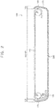
- FIG. 1 is a cross-sectional diagram of an embodiment of a sliding display device 100.
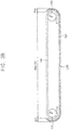
- FIG. 2 is a cross-sectional diagram of an embodiment of an expanded state of a display region DR of the sliding display device 100 in FIG. 1 .
- FIG. 3A is a cross-sectional diagram of one type of proposed sliding display device having a two-way sliding structure without an assistant roller, and
- FIG. 3B is a cross-sectional diagram of the display region DR in FIG. 3A in an expanded position.
- the sliding display device 100 may include a housing 120, a flexible display panel 140, a first main roller 160, a second main roller 170, and an assistant roller 180.
- the sliding display device 100 may include a driving integrated circuit that drives the flexible display panel 140, a power supply circuit that supplies driving power to the flexible display panel 140, etc., in the housing 120.
- the housing 120 may include a display region DR between a first edge region FER and a second edge region SER.
- the flexible display panel 140 may be exposed to a user (e.g., viewer) through the display region DR in a front direction of the housing 120.
- the sliding display device 100 may display an image on the flexible display panel 140 corresponding to the display region DR.
- the distance between the first edge region FER and the second edge region SER may change as the housing 120 is expanded or contracted in a first direction FRD and a second direction SRD opposite to the first direction FRD.
- the size of the display region DR is proportional to the distance between the first edge region FER and the second edge region SER.
- the size of the display region DR may therefore be increased or decreased as the housing 120 is expanded or contracted in the first direction FRD and the second direction SRD.
- the first edge region FER may be a top edge region (or, a bottom edge region) of the housing 120
- the second edge region SER may be the bottom edge region (or, the top edge region) of the housing 120, when the housing 120 is expanded or contracted in a top-bottom direction.
- the first edge region FER may be a right edge region (or, a left edge region) of the housing 120
- the second edge region SER may be the left edge region (or, the right edge region) of the housing 120, when the housing 120 is expanded or contracted in a left-right direction.
- the flexible display panel 140 may slide out from the housing 120 through the first and second edge regions FER and SER when the housing 120 is expanded in the first direction FRD and the second direction SRD.
- the flexible display panel 140 may slide into the housing 120 through the first and second edge regions FER and SER when the housing 120 is contracted in the first direction FRD and the second direction SRD. Because the flexible display panel 140 is manufactured with flexible materials, the flexible display panel 140 may be guided into an empty space of the housing 120 by the first main roller 160, the second main roller 170, and the assistant roller 180 after being slid into the housing 120.
- the housing 120 may include various shapes of path-structures to allow the flexible display panel 140 to slide into and out of the housing 120.
- an exposed area of the flexible display panel 140 may be exposed to the maximum extent (e.g., indicated by MAX-DR).
- the flexible display panel 140 may slide out from the housing 120 through the first and second edge regions FER and SER.
- the flexible display panel 140 may slide into the housing 120 through the first and second edge regions FER and SER.
- the housing 120 may be manufactured with stretchable materials that expand and/or contract in the first direction FRD and the second direction SRD.
- the housing 120 may include a mechanical structure (e.g., a spring structure, etc.) that expands and/or contracts in the first direction FRD and the second direction SRD.
- the flexible display panel 140 may include a plurality of pixels.
- the pixels may include red color (R) displaying pixels, green color (G) displaying pixels, and blue color (B) displaying pixels.
- the pixels may include red color (R) displaying pixels, green color (G) displaying pixels, blue color (B) displaying pixels, and white color (W) displaying pixels.
- the flexible display panel 140 may be driven by the driving integrated circuit to display (or, output) an image using the pixels.
- the driving integrated circuit may include, for example, a scan driver, a data driver, a timing controller, etc.
- the flexible display panel 140 may be an organic light emitting display (OLED) panel with organic light emitting diodes.
- the flexible display panel 140 may be a liquid crystal display (LCD) panel that includes liquid crystals.
- the flexible display panel 140 may be a different type of panel in another embodiment.
- the first main roller 160 may guide a first panel region of the flexible display panel 140 that slides into the housing 120 through the first edge region FER and into an empty space of the housing 120.
- the first main roller 160 may allow the first panel region of the flexible display panel 140 to move along a first moving path in the empty space of the housing 120.
- the first moving path may be a path corresponding to the second direction SRD from the first edge region FER to the second edge region SER.
- the second main roller 170 may allow a second panel region of the flexible display panel 140 to slide into the housing 120 through the second edge region SER and into the empty space of the housing 120.
- the radius of rotation R of the second main roller 170 may be equal to a radius of rotation R of the first main roller 160 or may be different from the radius of rotation R of the first main roller 160.
- a user may perceive that the display region DR adjacent to the first edge region FER and the display region DR adjacent to the second edge region SER are symmetrical.
- the assistant roller 180 may assist the second main roller 170 in moving the second panel region of the flexible display panel 140 along a second moving path, which does not intersect the first moving path, in the empty space of the housing 120.
- the second moving path may extend from the second edge region SER to the first edge region FER in the first direction FRD.
- the assistant roller 180 may be apart from the second main roller 170.
- the radius of rotation R' of the assistant roller 180 may be different from the radius of rotation R of the second main roller 170.
- the assistant roller 180 may prevent the second panel region of the flexible display panel 140 from colliding with the first panel region of the flexible display panel 140 (e.g., may prevent the second moving path of the second panel region of the flexible display panel 140 from intersecting the first moving path of the first panel region of the flexible display panel 140).
- the radius of rotation R' of the assistant roller 180 may therefore be relatively small relative to the thickness of the sliding display device 100.
- the radius of rotation R' of the assistant roller 180 may be less than the radius of rotation R of the second main roller 170.
- the radius of rotation R' of the assistant roller 180 may be equal to or greater than the radius of rotation R of the second main roller 170.
- the proposed sliding display device has a two-way sliding structure without assistant roller 180.
- a first moving path of the first panel region of the flexible display panel 140 may be the same as (or intersect) a second moving path of the second panel region of the flexible display panel 140.
- the first moving path is determined by the first main roller 160 and the second moving path is determined by the second main roller 170.
- the second main roller 170 may have a radius of rotation R equal to the radius of rotation R of the first main roller 160.
- the size of the flexible display panel 140 may be determined to allow the first panel region of the flexible display panel 140 to slide into the housing 120 through the first edge region FER without colliding with the second panel region of the flexible display panel 140, that slides into the housing 120 through the second edge region SER.
- an exposed area of the flexible display panel 140 (i.e., the display region DR) of the proposed sliding display device may be smaller than an exposed area of the flexible display panel 140 of the sliding display device 100 including assistant roller 180, when the exposed area of the flexible display panel 140 is expanded to the maximum extent (e.g., MAX-DR') as the housing 120 is expanded to the maximum extent in the first direction FRD and the second direction SRD (e.g., EXR').
- the maximum extent e.g., MAX-DR'
- the housing 120 is expanded to the maximum extent in the first direction FRD and the second direction SRD (e.g., EXR').
- the proposed sliding display device achieves a maximum size of the flexible display panel 140, by including the first and second main rollers 160 and 170 with different radiuses of rotation, a user may perceive the display region DR adjacent to the first edge region FER and the display region DR adjacent to the second edge region SER to be asymmetrical.
- the sliding display device 100 of the present embodiment may have a two-way sliding structure, in which the flexible display panel 140 slides into the housing 120 through the first and second edge regions FER and SER of the housing 120, and then is guided into the empty space of the housing 120.
- the sliding display device 100 includes the first main roller 160 that allows the first panel region of the flexible display panel 140 to slide into the housing 120 through the first edge region FER along the first moving path in the empty space of the housing 120.
- the second main roller 170 and the assistant roller 180 allow the second panel region of the flexible display panel 140 to slide into the housing 120 through the second edge region SER along the second moving path, which does not intersect the first moving path, in the empty space of the housing 120.
- the sliding display device 100 may achieve an increased or maximum size of the flexible display panel 140 by using the empty space of the housing 120 to an increased or maximum extent, and therefore may allow a user to perceive that the display region DR adjacent to the first edge region FER and the display region DR adjacent to the second edge region SER are symmetrical.
- one assistant roller 180 is used to assist the second main roller 170.
- two or more assistant rollers 180 may be included to assist the second main roller 170.
- FIGS. 4A-4C illustrates various embodiments of edge regions of a housing 120 in the sliding display device 100 of FIG. 1 .
- a housing 120a in the sliding display device 100 may include the first edge region FER and the second edge region SER.
- the display region DR1 between the first edge region FER and the second edge region SER may include the flat panel region of the flexible display panel 140. The user may not perceive a curved panel region of the flexible display panel 140, and thus may watch an image displayed on the flat panel region of the flexible display panel 140.
- the housing 120b in the sliding display device 100 may include the first edge region FER and the second edge region SER which allow both the flat panel region and the curved panel region of the flexible display panel 140 to be exposed to a user.
- the display region DR2 between the first edge region FER and the second edge region SER may include the flat panel region and the curved panel region of the flexible display panel 140.
- the user may not perceive the first edge region FER and the second edge region SER when the user observes the sliding display device 100 in front of the housing 120b of the sliding display device 100.
- the user may watch an image displayed on both the flat panel region and the curved panel region of the flexible display panel 140.
- an icon for executing an application program displayed on the flat panel region of the flexible display panel 140 may be displayed on the curved panel region of the flexible display panel 140.
- the housing 120c in the sliding display device 100 may include the first edge region FER and the second edge region SER which allow both the flat panel region and a portion of the curved panel region of the flexible display panel 140 to be exposed to the user.
- the display region DR3 between the first edge region FER and the second edge region SER may include the flat panel region and the portion of the curved panel region of the flexible display panel 140. In this case, a user may watch an image displayed on both the flat panel region and the portion of the curved panel region of the flexible display panel 140.
- the user may perceive that the display region DR1, DR2, and DR3 adjacent to the first edge region FER and the display region DR1, DR2, and DR3 adjacent to the second edge region SER to be symmetrical.
- FIG. 5 illustrates another embodiment of a sliding display device 200 in cross-section.
- the sliding display device 200 may include a housing 220, a flexible display panel 240, a first main roller 260, a second main roller 270, a first assistant roller 280, and a second assistant roller 290.
- the sliding display device 200 may include a driving integrated circuit that drives the flexible display panel 240, a power supply circuit that supplies driving power to the flexible display panel 240, etc., in the housing 220.
- the housing 220 may include a display region DR between a first edge region FER and a second edge region SER.
- the flexible display panel 240 may be exposed to a user through the display region DR in a front direction of the housing 220.
- the sliding display device 200 may display an image on the flexible display panel 240 corresponding to the display region DR.
- the distance between the first edge region FER and the second edge region SER may change as the housing 220 is expanded or contracted in a first direction FRD and a second direction SRD opposite to the first direction FRD.
- the size of the display region DR is proportional to the distance between the first edge region FER and the second edge region SER, the size of the display region DR may be increased or decreased as housing 220 is expanded or contracted in the first direction FRD and the second direction SRD.
- the first edge region FER may be a top edge region (or, a bottom edge region) of the housing 220
- the second edge region SER may be the bottom edge region (or, the top edge region) of the housing 220, when the housing 220 is expanded or contracted in a top-bottom direction.
- the first edge region FER may be a right edge region (or, a left edge region) of the housing 220
- the second edge region SER may be the left edge region (or, the right edge region) of the housing 220, when the housing 220 is expanded or contracted in a left-right direction.
- the flexible display panel 240 may slide out from the housing 220 through the first and second edge regions FER and SER when the housing 220 is expanded in the first direction FRD and the second direction SRD.
- the flexible display panel 240 may slide into the housing 220 through the first and second edge regions FER and SER when the housing 220 is contracted in the first direction FRD and the second direction SRD.
- the flexible display panel 240 Since the flexible display panel 240 is manufactured with flexible materials, the flexible display panel 240 may be guided into an empty space of the housing 220 by the first main roller 260, the second main roller 270, the first assistant roller 280, and the second assistant roller 290, after sliding into the housing 220.
- the housing 220 may include various shapes of path-structures through which the flexible display panel 240 is moved in the housing 220.
- the flexible display panel 240 may include a plurality of pixels.
- the flexible display panel 240 may be driven by the driving integrated circuit.
- the flexible display panel 240 may display an image using the pixels.
- the first main roller 260 may guide a first panel region of the flexible display panel 240, which is slid into the housing 220 through the first edge region FER, into an empty space of the housing 220.
- the first assistant roller 280 may assist the first main roller 260 to move the first panel region of the flexible display panel 240 along a first moving path in the empty space of the housing 220.
- the first moving path may extend from the first edge region FER to the second edge region SER in the second direction SRD.
- the first assistant roller 280 may be apart from the first main roller 260.
- the second main roller 270 may guide a second panel region of the flexible display panel 240, which is slid into the housing 220 through the second edge region SER, into the empty space of the housing 220.
- the radius of rotation R of the second main roller 270 may be equal to a radius of rotation R of the first main roller 260.
- a user may perceive the display region DR adjacent to the first edge region FER and the display region DR adjacent to the second edge region SER to be symmetrical.
- the second assistant roller 290 may assist the second main roller 270 to allow the second panel region of the flexible display panel 240 to move along a second moving path that does not intersect the first moving path in the empty space of the housing 220.
- the second moving path may extend from the second edge region SER to the first edge region FER in the first direction FRD.
- the second assistant roller 290 may be apart from the second main roller 270.
- the radius of rotation R' of the first assistant roller 280 may be different from a radius of rotation R" of the second assistant roller 290. In another example embodiment, the radius of rotation R' of the first assistant roller 280 may be equal to the radius of rotation R" of the second assistant roller 290. In this case, to prevent the first moving path of the first panel region of the flexible display panel 240 from intersecting the second moving path of the second panel region of the flexible display panel 240, a relative location of the first assistant roller 280 from the first main roller 260 may be different from a relative location of the second assistant roller 290 from the second main roller 270.
- the radius of rotation R' of the first assistant roller 280 may be different from the radius of rotation R of the first main roller 260
- the radius of rotation R" of the second assistant roller 290 may be different from the radius of rotation R of the second main roller 270.
- the first and second assistant rollers 280 and 290 prevent the second panel region of the flexible display panel 240 from colliding with the first panel region of the flexible display panel 240 (e.g., prevent the second moving path of the second panel region of the flexible display panel 240 from intersecting the first moving path of the first panel region of the flexible display panel 240), the radius of rotation R' of the first assistant roller 280 and the radius of rotation R" of the second assistant roller 290 may be relatively small when considering the thickness of the sliding display device 200.
- the radius of rotation R' of the first assistant roller 280 may be less than the radius of rotation R of the first main roller 260.
- the radius of rotation R" of the second assistant roller 290 may be less than the radius of rotation R of the second main roller 270.
- the radius of rotation R' of the first assistant roller 280 may be equal to or greater than the radius of rotation R of the first main roller 260
- the radius of rotation R" of the second assistant roller 290 may be equal to or greater than the radius of rotation R of the second main roller 270.
- the sliding display device 200 may therefore have a two-way sliding structure, in which the flexible display panel 240 slides into the housing 220 through the first and second edge regions FER and SER of the housing 220 and then is guided into the empty space of the housing 220.
- the sliding display device 200 includes the first main roller 260 and the first assistant roller 280 allow the first panel region of the flexible display panel 240 to slide into the housing 220 through the first edge region FER along the first moving path in the empty space of the housing 220.
- the second main roller 270 and the second assistant roller 290 allow the second panel region of the flexible display panel 240 to slide into the housing 220 through the second edge region SER along the second moving path that does not intersect the first moving path in the empty space of the housing 220.
- the sliding display device 200 may achieve an increased or maximum size of the flexible display panel 240 by utilizing the empty space of the housing 220 to the an increased or maximum amount.
- a user perceives the display region DR adjacent to the first edge region FER and the display region DR adjacent to the second edge region SER to be symmetrical.
- FIG. 5 shows one first assistant roller 280 that assists the first main roller 260 and one second assistant roller 290 that assists the second main roller 270.
- two or more first assistant rollers 280 may assist the first main roller 260
- two or more second assistant rollers 290 may assist the second main roller 270.
- FIG. 6 illustrates another embodiment of a sliding display device 300 which may include a housing 320, a flexible display panel 340, a first main roller 360, a second main roller 370, and a support beam 380.
- the sliding display device 300 may include a driving integrated circuit that drives the flexible display panel 340, a power supply circuit that supplies driving power to the flexible display panel 340, etc., in housing 320.
- the housing 320 may include a display region DR between a first edge region FER and a second edge region SER.
- the flexible display panel 340 may be exposed to a user through the display region DR in a front direction of the housing 320.
- the sliding display device 300 may display an image on the flexible display panel 340 corresponding to the display region DR.
- the distance between the first edge region FER and the second edge region SER may change as the housing 320 is expanded or contracted in a first direction FRD and a second direction SRD opposite to the first direction FRD.
- the size of the display region DR is proportional to the distance between the first edge region FER and the second edge region SER, the size of the display region DR may be increased or decreased as the housing 320 is expanded or contracted in the first direction FRD and the second direction SRD.
- the first edge region FER may be a top edge region (or, a bottom edge region) of the housing 320 and the second edge region SER may be the bottom edge region (or, the top edge region) of the housing 320 when the housing 320 is expanded or contracted in a top-bottom direction.
- the first edge region FER may be a right edge region (or, a left edge region) of the housing 320 and the second edge region SER may be the left edge region (or, the right edge region) of the housing 320 when the housing 320 is expanded or contracted in a left-right direction.
- the flexible display panel 340 may slide out from the housing 320 through the first and second edge regions FER and SER when the housing 320 is expanded in the first direction FRD and the second direction SRD.
- the flexible display panel 340 may slide into the housing 320 through the first and second edge regions FER and SER when the housing 320 is contracted in the first direction FRD and the second direction SRD.
- the flexible display panel 340 is manufactured with flexible materials.
- the flexible display panel 340 may be guided into an empty space of the housing 320 by the first main roller 360, the second main roller 370, and the support beam 380 after being slid into the housing 320.
- the housing 320 may include various shapes of path-structures through which the flexible display panel 340 is moved in the housing 320.
- the flexible display panel 340 may include a plurality of pixels.
- the flexible display panel 340 may be driven by the driving integrated circuit.
- the flexible display panel 340 may display an image using the pixels.
- the first main roller 360 may guide a first panel region of the flexible display panel 340, that is slid into the housing 320 through the first edge region FER, into an empty space of the housing 320 and may move the first panel region of the flexible display panel 340 along a first moving path in the empty space of the housing 320.
- the first moving path may be a path corresponding to the second direction SRD from the first edge region FER to the second edge region SER.
- the second main roller 370 may guide a second panel region of the flexible display panel 340, which is slid into the housing 320 through the second edge region SER, into the empty space of the housing 320.
- the radius of rotation R of the second main roller 370 may be equal to a radius of rotation R of the first main roller 360. Since the radius of rotation R of the second main roller 370 is equal to the radius of rotation R of the first main roller 360, a user may perceive the display region DR adjacent to the first edge region FER and the display region DR adjacent to the second edge region SER to be symmetrical.
- the support beam 380 may support the second panel region of the flexible display panel 340 to move the second panel region of the flexible display panel 340 along a second moving path that does not intersect the first moving path in the empty space of housing 320.
- the second moving path may extend from the second edge region SER to the first edge region FER in the first direction FRD.
- the support beam 380 may have, for example, a cylindrical shape to reduce or minimize frictional force between the support beam 380 and the flexible display panel 340.
- the support beam 380 may be apart from the second main roller 370.
- the support beam 380 may prevent the second panel region of the flexible display panel 340 from colliding with the first panel region of the flexible display panel 340 (e.g., prevent the second moving path of the second panel region of the flexible display panel 340 from intersecting the first moving path of the first panel region of the flexible display panel 340).
- the radius of curvature of the support beam 380 may be relatively small considering the thickness of the sliding display device 300. Thus, as illustrated in FIG. 6 , the radius of curvature of the support beam 380 may be less than the radius of rotation R of the second main roller 370. In some example embodiments, the radius of curvature of the support beam 380 may be equal to or greater than the radius of rotation R of the second main roller 370.
- the sliding display device 300 may have a two-way sliding structure, in which the flexible display panel 340 slides into the housing 320 through the first and second edge regions FER and SER of the housing 320 and then is guided into the empty space of the housing 320.
- the sliding display device 300 includes the first main roller 360 that allows the first panel region of the flexible display panel 340 to slide into the housing 320 through the first edge region FER along the first moving path in the empty space of the housing 320.
- the second main roller 370 and the support beam 380 allows the second panel region of the flexible display panel 340 to slide into the housing 320 through the second edge region SER along the second moving path that does not intersect the first moving path in the empty space of the housing 320.
- the sliding display device 300 may achieve an increased or maximum size of the flexible display panel 340 by utilizing the empty space of the housing 320 to an increased or maximum extent. Also, a user perceives the display region DR adjacent to the first edge region FER and the display region DR adjacent to the second edge region SER to be symmetrical.
- one support beam 380 assists the second main roller 370. In some example embodiments, two or more support beams 380 may assist the second main roller 370.
- FIG. 7 illustrates another embodiment of a sliding display device 400 which may include a housing 420, a flexible display panel 440, a first main roller 460, a second main roller 470, a first support beam 480, and a second support beam 490.
- the sliding display device 400 may include a driving integrated circuit that drives the flexible display panel 440, a power supply circuit that supplies driving power to the flexible display panel 440, etc., in the housing 420.
- the housing 420 may include a display region DR between a first edge region FER and a second edge region SER.
- the flexible display panel 440 may be exposed to a user through the display region DR in a front direction of the housing 420.
- the sliding display device 400 may display an image on the flexible display panel 440 corresponding to the display region DR.
- the distance between the first edge region FER and the second edge region SER may change as the housing 420 is expanded or contracted in a first direction FRD and a second direction SRD, which is opposite to the first direction FRD.
- the size of the display region DR is proportional to the distance between the first edge region FER and the second edge region SER.
- the size of the display region DR may be increased or decreased as the housing 420 is expanded or contracted in the first direction FRD and the second direction SRD.
- the first edge region FER may be a top edge region (or, a bottom edge region) of the housing 420
- the second edge region SER may be the bottom edge region (or, the top edge region) of the housing 420, when the housing 420 is expanded or contracted in a top-bottom direction.
- the first edge region FER may be a right edge region (or, a left edge region) of the housing 420
- the second edge region SER may be the left edge region (or, the right edge region) of the housing 420, when the housing 420 is expanded or contracted in a left-right direction.
- the flexible display panel 440 may slide out from the housing 420 through the first and second edge regions FER and SER when the housing 420 is expanded in the first direction FRD and the second direction SRD.
- the flexible display panel 440 may slide into the housing 420 through the first and second edge regions FER and SER when the housing 420 is contracted in the first direction FRD and the second direction SRD.
- the flexible display panel 440 Since the flexible display panel 440 is manufactured with flexible materials, the flexible display panel 440 may be guided into an empty space of the housing 420 by the first main roller 460, the second main roller 470, the first support beam 480, and the second support beam 490 after being slid into the housing 420.
- the housing 420 may include various shapes of path-structures through which the flexible display panel 440 is moved in the housing 420.
- the flexible display panel 440 may include a plurality of pixels.
- the flexible display panel 440 may be driven by the driving integrated circuit.
- the flexible display panel 440 may display an image using the pixels.
- the first main roller 460 may guide a first panel region of the flexible display panel 440, which is slid into the housing 420 through the first edge region FER, into an empty space of the housing 420.
- the first support beam 480 may support the first panel region of the flexible display panel 440, to allow the first panel region of the flexible display panel 440 to move along a first moving path in the empty space of the housing 420.
- the first moving path may be a path corresponding to the second direction SRD from the first edge region FER to the second edge region SER.
- the first support beam 480 may have, for example, a cylindrical shape to reduce or minimize frictional force between the first support beam 480 and the flexible display panel 440.
- the first support beam 480 may be apart from the first main roller 460.
- the second main roller 470 may guide a second panel region of the flexible display panel 440, which is slid into the housing 420 through the second edge region SER, into the empty space of the housing 420.
- the radius of rotation R of the second main roller 470 may be equal to a radius of rotation R of the first main roller 460. Since the radius of rotation R of the second main roller 470 is equal to the radius of rotation R of the first main roller 460, a user may perceive the display region DR adjacent to the first edge region FER and the display region DR adjacent to the second edge region SER to be symmetrical.
- the second support beam 490 may support the second panel region of the flexible display panel 440, to allow the second panel region of the flexible display panel 440 to move along a second moving path that does not intersect the first moving path in the empty space of the housing 420.
- the second moving path may correspond to the first direction FRD from the second edge region SER to the first edge region FER.
- the second support beam 490 may have, for example, a cylindrical shape to reduce or minimize frictional force between the second support beam 490 and the flexible display panel 440.
- the second support beam 490 may be apart from the second main roller 470.
- the radius of curvature of the first support beam 480 may be different from a radius of curvature of the second support beam 490.
- the radius of curvature of the first support beam 480 may be equal to the radius of curvature of the second support beam 490.
- the relative location of the first support beam 480 from the first main roller 460 may be different from a relative location of the second support beam 490 from the second main roller 470.
- the radius of curvature of the first support beam 480 may be different from the radius of rotation R of the first main roller 460
- the radius of curvature of the second support beam 490 may be different from the radius of rotation R of the second main roller 470.
- the first and second support beams 480 and 490 may prevent the second panel region of the flexible display panel 440 from colliding with the first panel region of the flexible display panel 440 (e.g., prevent the second moving path of the second panel region of the flexible display panel 440 from intersecting the first moving path of the first panel region of flexible display panel 440).
- the radius of curvature of the first support beam 480 and the radius of curvature of the second support beam 490 may be relatively small considering a thickness of the sliding display device 400.
- the radius of curvature of the first support beam 480 may be less than the radius of rotation R of the first main roller 460
- the radius of curvature of the second support beam 490 may be less than the radius of rotation R of the second main roller 470.
- the radius of curvature of the first support beam 480 may be equal to or greater than the radius of rotation R of the first main roller 460
- the radius of curvature of the second support beam 490 may be equal to or greater than the radius of rotation R of the second main roller 470.
- the sliding display device 400 may have a two-way sliding structure, in which the flexible display panel 440 slides into the housing 420 through the first and second edge regions FER and SER of the housing 420 and then is guided into the empty space of the housing 420.
- the sliding display device 400 includes the first main roller 460 and the first support beam 480 that allow the first panel region of the flexible display panel 440 to slide into the housing 420 through the first edge region FER along the first moving path in the empty space of the housing 420.
- the second main roller 470 and the second support beam 490 allow the second panel region of the flexible display panel 440 to slide into the housing 420 through the second edge region SER along the second moving path that does not intersect the first moving path in the empty space of the housing 420.
- the sliding display device 400 may achieve an increased or maximum size of the flexible display panel 440 by utilizing the empty space of the housing 420 to an increased or maximum extent, and may allow the user to perceive that the display region DR adjacent to the first edge region FER and the display region DR adjacent to the second edge region SER are symmetrical.
- one first support beam 480 assists the first main roller 460 and one second support beam 490 assists the second main roller 470.
- two or more first support beams 480 may assist the first main roller 460 and two or more second support beams 490 may assist the second main roller 470.
- FIG. 8 illustrates another embodiment of a sliding display device 500 which may include a housing 520, a flexible display panel 540, a first support beam 560, and a second support beam 570.
- the sliding display device 500 may include a driving integrated circuit that drives the flexible display panel 540, a power supply circuit that supplies driving power to the flexible display panel 540, etc., in the housing 520.
- the housing 520 may include a display region DR that is between a first edge region FER and a second edge region SER.
- the flexible display panel 540 may be exposed to a user through the display region DR in a front direction of the housing 520.
- the sliding display device 500 may display an image on the flexible display panel 540 corresponding to the display region DR.
- the distance between the first edge region FER and the second edge region SER may change as the housing 520 is expanded or contracted in a first direction FRD and a second direction SRD, which is opposite to the first direction FRD.
- the size of the display region DR may be proportional to the distance between the first edge region FER and the second edge region SER. The size of the display region DR may therefore be increased or decreased as the housing 520 is expanded or contracted in the first direction FRD and the second direction SRD.
- the first edge region FER may be a top edge region (or, a bottom edge region) of the housing 520
- the second edge region SER may be the bottom edge region (or, the top edge region) of the housing 520, when the housing 520 is expanded or contracted in a top-bottom direction.
- the first edge region FER may be a right edge region (or, a left edge region) of the housing 520
- the second edge region SER may be the left edge region (or, the right edge region) of the housing 520, when the housing 520 is expanded or contracted in a left-right direction.
- the flexible display panel 540 may slide out from the housing 520 through the first and second edge regions FER and SER when the housing 520 is expanded in the first direction FRD and the second direction SRD.
- the flexible display panel 540 may slide into the housing 520 through the first and second edge regions FER and SER when the housing 520 is contracted in the first direction FRD and the second direction SRD.
- the flexible display panel 540 Since the flexible display panel 540 is manufactured with flexible materials, the flexible display panel 540 may be guided into an empty space of the housing 520 by the first support beam 560 and the second support beam 570, after sliding into the housing 520.
- the housing 520 may include various shapes of path-structures through which the flexible display panel 540 is moved in the housing 520.
- the flexible display panel 540 may include a plurality of pixels.
- the flexible display panel 540 may be driven by the driving integrated circuit and may display an image using the pixels.
- the first support beam 560 may have, for example, a cylindrical shape with a radius of curvature R.
- the first support beam 560 may guide a first panel region of the flexible display panel 540, which is slid into the housing 520 through the first edge region FER, into an empty space of the housing 520.
- the first support beam 560 may support the first panel region of the flexible display panel 540, to allow the first panel region of the flexible display panel 540 to move along a first moving path in the empty space of the housing 520.
- the second support beam 570 may have, for example, a cylindrical shape with a first radius of curvature R in a front direction of the housing 520 and may have a second radius of curvature R' that is different from the first radius of curvature R in a back direction of the housing 520.
- the second support beam 570 may guide a second panel region of the flexible display panel 540, which is slid into the housing 520 through the second edge region SER, into the empty space of the housing 520.
- the second support beam 570 may support the second panel region of the flexible display panel 540, to allow the second panel region of the flexible display panel 540 to move along a second moving path that does not intersect the first moving path in the empty space of the housing 520. Since the first radius of curvature R of the second support beam 570 may be equal to the radius of curvature R of the first support beam 560 in the front direction of the housing 520. Thus, a user may perceive the display region DR adjacent to the first edge region FER and the display region DR adjacent to the second edge region SER to be symmetrical.
- the second radius of curvature R' of the second support beam 570 may be different from the radius of curvature R of the first support beam 560 in the back direction of the housing 520.
- the first moving path of the first panel region of the flexible display panel 540 may be prevented from intersecting the second moving path of the second panel region of the flexible display panel 540 in the empty space of the housing 520.
- the first radius of curvature R of the second support beam 570 may be greater than the second radius of curvature R' of the second support beam 570.
- the sliding display device 500 may have a two-way sliding structure, in which the flexible display panel 540 slides into the housing 520 through the first and second edge regions FER and SER of the housing 520 and then is guided into the empty space of the housing 520.
- the sliding display device 500 includes the first support beam 560 and a second support beam 570.
- the first support beam 560 allows the first panel region of the flexible display panel 540 to slide into the housing 520 through the first edge region FER along the first moving path in the empty space of the housing 520.
- the second support beam 570 allows the second panel region of the flexible display panel 540 to slide into the housing 520 through the second edge region SER along the second moving path that does not intersect the first moving path in the empty space of the housing 520.
- the sliding display device 500 may achieve an increased or maximum size of the flexible display panel 540 by utilizing the empty space of the housing 520 to an increased or maximum extent. Also, these features may allow a user to perceive the display region DR adjacent to the first edge region FER and the display region DR adjacent to the second edge region SER to be symmetrical.
- FIG. 9 illustrates another embodiment of a sliding display device 600 which may include a housing 620, a flexible display panel 640, a first support beam 660, and a second support beam 670.
- the sliding display device 600 may include a driving integrated circuit to drive the flexible display panel 640, a power supply circuit to supply driving power to the flexible display panel 640, etc., in the housing 620.
- the housing 620 may include a display region DR between a first edge region FER and a second edge region SER.
- the flexible display panel 640 may be exposed to a user through the display region DR in a front direction of the housing 620.
- the sliding display device 600 may display an image on the flexible display panel 640 corresponding to the display region DR.
- the distance between the first edge region FER and the second edge region SER may change as the housing 620 is expanded or contracted in a first direction FRD and a second direction SRD, which is opposite to the first direction FRD.
- a size of the display region DR is proportional to the distance between the first edge region FER and the second edge region SER, the size of the display region DR may therefore be increased or decreased as the housing 620 is expanded or contracted in the first direction FRD and the second direction SRD.
- the first edge region FER may be a top edge region (or, a bottom edge region) of the housing 620
- the second edge region SER may be the bottom edge region (or, the top edge region) of the housing 620, when the housing 620 is expanded or contracted in a top-bottom direction.
- the first edge region FER may be a right edge region (or, a left edge region) of the housing 620
- the second edge region SER may be the left edge region (or, the right edge region) of the housing 620, when the housing 620 is expanded or contracted in a left-right direction.
- the flexible display panel 640 may slide out from the housing 620 through the first and second edge regions FER and SER when the housing 620 is expanded in the first direction FRD and the second direction SRD.
- the flexible display panel 640 may slide into the housing 620 through the first and second edge regions FER and SER when the housing 620 is contracted in the first direction FRD and the second direction SRD.
- the flexible display panel 640 Since the flexible display panel 640 is manufactured with flexible materials, the flexible display panel 640 may be guided into an empty space of the housing 620 by the first support beam 660 and the second support beam 670, after sliding into the housing 620.
- the housing 620 may include various shapes of path-structures to allow the flexible display panel 640 to move in the housing 620.
- the flexible display panel 640 may include a plurality of pixels.
- the flexible display panel 640 may be driven by the driving integrated circuit.
- the flexible display panel 640 may display an image using the pixels.
- the first support beam 660 may have, for example, a cylindrical shape with a radius of curvature R.
- the first support beam 660 may guide a first panel region of the flexible display panel 640, which slides into the housing 620 through the first edge region FER, into an empty space of the housing 620.
- the first support beam 660 may support the first panel region of the flexible display panel 640, to allow the first panel region of the flexible display panel 640 to move along a first moving path in the empty space of the housing 620.
- the second support beam 670 may have, for example, a cylindrical shape with a first radius of curvature R in a front direction of the housing 620 and a second radius of curvature R' different from the first radius of curvature R in a back direction of the housing 620.
- the second support beam 670 may guide a second panel region of the flexible display panel 640, which slides into the housing 620 through the second edge region SER, into the empty space of the housing 620.
- the second support beam 670 may support the second panel region of the flexible display panel 640, to allow the second panel region of the flexible display panel 640 to move along a second moving path that does not intersect the first moving path in the empty space of the housing 620.
- the first radius of curvature R of the second support beam 670 is equal to the radius of curvature R of the first support beam 660 in the front direction of the housing 620, a user may perceive the display region DR adjacent to the first edge region FER and the display region DR adjacent to the second edge region SER to be symmetrical.
- the first moving path of the first panel region of the flexible display panel 640 may be prevented from intersecting the second moving path of the second panel region of the flexible display panel 640 in the empty space of the housing 620.
- the first radius of curvature R of the second support beam 670 may be less than the second radius of curvature R' of the second support beam 670.
- the sliding display device 600 may have a two-way sliding structure, in which the flexible display panel 640 slides into the housing 620 through the first and second edge regions FER and SER of the housing 620 and then is guided into the empty space of the housing 620.
- the sliding display device 600 includes the first support beam 660 and a second support beam 670.
- the first support beam 660 moves the first panel region of the flexible display panel 640, which slides into the housing 620 through the first edge region FER, along the first moving path in the empty space of the housing 620.
- the second support beam 670 moves the second panel region of the flexible display panel 640, which slides into the housing 620 through the second edge region SER, along the second moving path that does not intersect the first moving path in the empty space of the housing 620.
- the sliding display device 600 may achieve an increased or maximum size of the flexible display panel 640 by utilizing the empty space of the housing 620 to an increased or maximum extent. Also, a user may perceive the display region DR adjacent to the first edge region FER and the display region DR adjacent to the second edge region SER to be symmetrical.
- FIG. 10 illustrates an embodiment of an electronic device 700 which may include a processor 710, a memory device 720, a storage device 730, an input/output (I/O) device 740, a sliding detection sensor 750, and a sliding display device 760.
- the sliding display device 760 may correspond to the sliding display device of any of the aforementioned embodiments.
- the sliding display device 760 may be implemented by an organic light emitting display (OLED) device, a liquid crystal display (LCD) device, or another type of display device.
- the electronic device 700 may include a plurality of ports, for example, for communicating with a video card, a sound card, a memory card, a universal serial bus (USB) device, or other electronic devices.
- the electronic device 700 may be implemented, for example, as a cellular phone, a smart phone, a video phone, a smart pad, a smart watch, a tablet PC, a car navigation system, a television, a computer monitor, a laptop, or a head mounted display (HMD) device.
- HMD head mounted display
- the processor 710 may perform various computing functions.
- the processor 710 may control a displaying operation of the sliding display device 760 based on a sliding detection signal output from the sliding detection sensor 750.
- the sliding detection signal may indicate, for example, whether a flexible display panel is slid into the housing of the sliding display device 760 and/or whether the flexible display panel is slid out from the housing.
- the processor 710 may be, for example, a micro processor, a central processing unit (CPU), an application processor (AP), or another processing device or controller.
- the processor 710 may be coupled to other components via an address bus, a control bus, a data bus, or another communication path. Further, the processor 710 may be coupled to an extended bus such as a peripheral component interconnection (PCI) bus.
- PCI peripheral component interconnection
- the memory device 720 may store data for operations of the electronic device 700.
- the memory device 720 may be or include at least one non-volatile memory device such as an erasable programmable read-only memory (EPROM) device, an electrically erasable programmable read-only memory (EEPROM) device, a flash memory device, a phase change random access memory (PRAM) device, a resistance random access memory (RRAM) device, a nano floating gate memory (NFGM) device, a polymer random access memory (PoRAM) device, a magnetic random access memory (MRAM) device, a ferroelectric random access memory (FRAM) device, etc, and/or at least one volatile memory device such as a dynamic random access memory (DRAM) device, a static random access memory (SRAM) device, a mobile DRAM device, etc.
- DRAM dynamic random access memory
- SRAM static random access memory
- the storage device 730 may include a solid state drive (SSD) device, a hard disk drive (HDD) device, a CD-ROM device, etc.
- the I/O device 740 may include an input device such as a keyboard, a keypad, a mouse device, a touchpad, a touch-screen, etc, and an output device such as a printer, a speaker, etc.
- the electronic device 700 may include a power supply that supplies power for operations of the electronic device 700.
- the sliding detection sensor 750 may generate the sliding detection signal for output to the processor 710.
- the sliding display device 760 may perform a displaying operation suitable to an exposure of the flexible display panel.
- the sliding display device 760 may perform a displaying operation according to a size of a display region (e.g., a region of the flexible display panel that is exposed to a user).
- the sliding display device 760 may be coupled to other components via the buses or other communication links.
- the sliding display device 760 may be in the I/O device 740.
- the sliding display device 760 may have a two-way sliding structure, in which the flexible display panel slides into the housing through first and second edge regions and then is guided into an empty space of the housing.
- the sliding display device 760 may include a display region that is between a first edge region and a second edge region.
- the sliding display device 760 may include the housing that is expanded or contracted in a first direction and a second direction opposite to the first direction (e.g., a distance between the first edge region and the second edge region is changed).
- the flexible display panel slides out from the housing through the first and second edge regions to expand the housing and slides into the housing through the first and second edge regions to contract the housing.
- the sliding display device 760 may include a first main roller and a second main roller.
- the first main roller guides a first panel region of the flexible display panel, which is slid into the housing through the first edge region, into an empty space of the housing and moves the first panel region along a first moving path in the empty space of the housing.
- the second main roller guides a second panel region of the flexible display panel, which is slid into the housing through the second edge region, into the empty space of the housing.
- the radius of rotation of the first main roller is equal to a radius of rotation of the second main roller.
- An assistant roller may assist the second main roller to move the second panel region along a second moving path that does not intersect the first moving path in the empty space of the housing.
- the sliding display device 760 may include a first main roller, a first assistant roller, a second main roller, and a second assistant roller.
- the first main roller guides a first panel region of the flexible display panel, which is slid into the housing through the first edge region, into an empty space of the housing.
- the first assistant roller assists the first main roller to move the first panel region along a first moving path in the empty space of the housing.
- the second main roller guides a second panel region of the flexible display panel, which is slid into the housing through the second edge region, into the empty space of the housing.
- the radius of rotation of the first main roller is equal to a radius of rotation of the second main roller.
- the second assistant roller assists the second main roller to move the second panel region along a second moving path that does not intersect the first moving path in the empty space of the housing.
- the sliding display device 760 may include a first main roller, a second main roller, and a support beam.
- the first main roller guides a first panel region of the flexible display panel, which is slid into the housing through the first edge region, into an empty space of the housing and moves the first panel region along a first moving path in the empty space of the housing.
- the second main roller guides a second panel region of the flexible display panel, which is slid into the housing through the second edge region, into the empty space of the housing.
- the radius of rotation of the first main roller is equal to a radius of rotation of the second main roller.
- the support beam supports the second panel region to allow the second panel region to move along a second moving path that does not intersect the first moving path in the empty space of the housing.
- the sliding display device 760 may include a first main roller, a second main roller, a first support beam, and a second support beam.
- the first main roller guides a first panel region of the flexible display panel, which is slid into the housing through the first edge region, into an empty space of the housing.
- the first support beam supports the first panel region to allow the first panel region to move along a first moving path in the empty space of the housing.
- the second main roller guides a second panel region of the flexible display panel, which is slid into the housing through the second edge region, into the empty space of the housing.
- the radius of rotation of the first main roller is equal to a radius of rotation of the second main roller.
- the second support beam supports the second panel region to allow the second panel region to move along a second moving path that does not intersect the first moving path in the empty space of the housing.
- the sliding display device 760 may include a first support beam and a second support beam.
- the first support beam guides a first panel region of the flexible display panel, which is slid into the housing through the first edge region, into an empty space of the housing, and supports the first panel region to allow the first panel region to move along a first moving path in the empty space of the housing.
- the first support beam may have, for example, a cylindrical shape with a first radius of curvature.
- the second support beam guides a second panel region of the flexible display panel, that is slid into the housing through the second edge region, into the empty space of the housing, and supports the second panel region to allow the second panel region to move along a second moving path that does not intersect the first moving path in the empty space of the housing.
- the second support beam may have, for example, a cylindrical shape with a first radius of curvature in a front direction of the housing and a second radius of curvature different from the first radius of curvature in a back direction of the housing.
- the sliding display device 760 includes at least one roller and/or at least one support beam to achieve an increased or maximum size of the flexible display panel, by utilizing the empty space of the housing to an increased or maximum extent. Also, these features may allow a user (e.g., a viewer) to perceive that the display region adjacent to the first edge region and the display region adjacent to the second edge region are symmetrical.
- the electronic device may be, for example, a cellular phone, a smart phone, a video phone, a smart pad, a smart watch, a tablet PC, a car navigation system, a television, a computer monitor, a laptop, or a head mounted display device.
Landscapes
- Engineering & Computer Science (AREA)
- Theoretical Computer Science (AREA)
- Physics & Mathematics (AREA)
- General Physics & Mathematics (AREA)
- Computer Hardware Design (AREA)
- General Engineering & Computer Science (AREA)
- Human Computer Interaction (AREA)
- Signal Processing (AREA)
- Mathematical Physics (AREA)
- Nonlinear Science (AREA)
- Devices For Indicating Variable Information By Combining Individual Elements (AREA)
- Microelectronics & Electronic Packaging (AREA)
- Chemical & Material Sciences (AREA)
- Crystallography & Structural Chemistry (AREA)
- Optics & Photonics (AREA)
- Electroluminescent Light Sources (AREA)
Abstract
Description
- One or more embodiments described herein relate to a sliding display device.
- The demand for portable electronic devices that display large-size images is increasing. A sliding display has been proposed in an attempt to satisfy this demand. Such a display includes a flexible display panel that slides into and out of a housing to respectively display small- and large-size images.
- However, such as display device has drawbacks, not the least of which includes an inefficient use of empty space in the housing when the flexible panel is inside the housing.
- In accordance with the invention a sliding display device is proposed comprising the features of claim 1. Advantageous embodiments are specified in the dependent claims.
- In accordance with one or more embodiments, a sliding display device may include a housing including a display region between a first edge region and a second edge region, a distance between the first edge region and the second edge region to change as the housing is expanded or contracted in a first direction and a second direction opposite to the first direction; a flexible display panel to slide out from the housing through the first and second edge regions as the housing is expanded and to slide into the housing through the first and second edge regions as the housing is contracted; a first main roller to guide a first panel region of the flexible display panel, that is slid into the housing through the first edge region, into an empty space of the housing and to allow the first panel region of the flexible display panel to move along a first moving path in the empty space of the housing; a second main roller to guide a second panel region of the flexible display panel, that is slid into the housing through the second edge region, into the empty space of the housing, a radius of rotation of the second main roller equal to a radius of rotation of the first main roller; and a further element to allow the second panel region of the flexible display panel to move along a second moving path not intersecting the first moving path in the empty space of the housing. The further element may be an assistant roller to assist the second main roller or a support beam.
- The assistant roller or the support beam may be separate from the second main roller. A radius of rotation of the assistant roller or of the support beam is different from the radius of rotation of the second main roller. A radius of rotation of the assistant roller or of the support beam may be equal to the radius of rotation of the second main roller.
- In accordance with one or more other embodiments, the sliding display device includes a housing including a display region between a first edge region and a second edge region, a distance between the first edge region and the second edge region to change as the housing is expanded or contracted in a first direction and a second direction opposite to the first direction; a flexible display panel to slide out from the housing through the first and second edge regions as the housing is expanded and to slide into the housing through the first and second edge regions as the housing is contracted; a first main roller to guide a first panel region of the flexible display panel, that is slid into the housing through the first edge region, into an empty space of the housing; a yet further element to assist the first main roller to allow the first panel region of the flexible display panel to move along a first moving path in the empty space of the housing; a second main roller to guide a second panel region of the flexible display panel, that is slid into the housing through the second edge region, into the empty space of the housing, a radius of rotation of the second main roller equal to a radius of rotation of the first main roller; and the assistant roller or the support beam to assist the second main roller to allow the second panel region of the flexible display panel to move along a second moving path that does not intersect the first moving path in the empty space of the housing. The yet further element may be an further assistant roller to assist the second main roller or a further support beam to support the first panel region of the flexible display panel.
- The further assistant roller may be separate from the first main roller. The assistant roller may be separate from the second main roller. A radius of rotation of the first assistant roller may be different from the radius of rotation of the first main roller, and a radius of rotation of the second assistant roller may be different from the radius of rotation of the second main roller. The radius of rotation of the first assistant roller may be different from the radius of rotation of the second assistant roller. The radius of rotation of the first assistant roller may be equal to the radius of rotation of the second assistant roller.
- In accordance with one or more other embodiments, a sliding display device includes a housing including a display region between a first edge region and a second edge region, a distance between the first edge region and the second edge region to change as the housing is expanded or contracted in a first direction and a second direction opposite to the first direction; a flexible display panel to slide out from the housing through the first and second edge regions as the housing is expanded and to slide into the housing through the first and second edge regions as the housing is contracted; a first main roller to guide a first panel region of the flexible display panel, that is slid into the housing through the first edge region, into an empty space of the housing, and to allow the first panel region of the flexible display panel to move along a first moving path in the empty space of the housing; a second main roller to guide a second panel region of the flexible display panel, that is slid into the housing through the second edge region, into the empty space of the housing, a radius of rotation of the second main roller equal to a radius of rotation of the first main roller; and a support beam to support the second panel region of the flexible display panel to allow the second panel region of the flexible display panel to move along a second moving path that does not intersect the first moving path in the empty space of the housing. The support beam may have a cylindrical shape. The support beam may be separate from the second main roller.
- In accordance with one or more other embodiments, a sliding display device includes a housing including a display region between a first edge region and a second edge region, a distance between the first edge region and the second edge region to change as the housing is expanded or contracted in a first direction and a second direction opposite to the first direction; a flexible display panel to be slide out from the housing through the first and second edge regions as the housing is expanded and to slide into the housing through the first and second edge regions as the housing is contracted; a first main roller to guide a first panel region of the flexible display panel, that is slid into the housing through the first edge region, into an empty space of the housing; a first support beam to support the first panel region of the flexible display panel to allow the first panel region of the flexible display panel to move along a first moving path in the empty space of the housing; a second main roller to guide a second panel region of the flexible display panel, that is slid into the housing through the second edge region, into the empty space of the housing, a radius of rotation of the second main roller equal to a radius of rotation of the first main roller; and a second support beam to support the second panel region of the flexible display panel to allow the second panel region of the flexible display panel to move along a second moving path that does not intersect the first moving path in the empty space of the housing. Each of the first support beam and the second support beam may have a cylindrical shape. The first support beam may be separate from the first main roller. The second support beam may be separate from the second main roller.
- In accordance with one or more other embodiments, a sliding display device includes a housing including a display region between a first edge region and a second edge region, a distance between the first edge region and the second edge region to change as the housing is expanded or contracted in a first direction and a second direction opposite to the first direction; a flexible display panel to slide out from the housing through the first and second edge regions as the housing is expanded and to slide into the housing through the first and second edge regions as the housing is contracted; a first support beam to guide a first panel region of the flexible display panel, that is slid into the housing through the first edge region, into an empty space of the housing and to support the first panel region of the flexible display panel to allow the first panel region of the flexible display panel to move along a first moving path in the empty space of the housing, the first support beam having a cylindrical shape with a radius of curvature; and a second support beam to guide a second panel region of the flexible display panel, that is slid into the housing through the second edge region, into the empty space of the housing and to support the second panel region of the flexible display panel to allow the second panel region of the flexible display panel to move along a second moving path that does not intersect the first moving path in the empty space of the housing, the second support beam having a cylindrical shape with a first radius of curvature in a front direction of the housing and a second radius of curvature in a back direction of the housing, wherein the radius of curvature of the first support beam is equal to the first radius of curvature of the second support beam, and the first radius of curvature of the second support beam is different from the second radius of curvature of the second support beam. The first radius of curvature of the second support beam may be greater than the second radius of curvature of the second support beam. The first radius of curvature of the second support beam may be less than the second radius of curvature of the second support beam.
- Features will become apparent to those of skill in the art by describing in detail exemplary embodiments with reference to the attached drawings in which:
-
FIG. 1 illustrates an embodiment of a sliding display device; -
FIG. 2 illustrates an embodiment of a display region in an expanded position; -
FIG. 3A illustrates one type of sliding display device that has been proposed, andFIG. 3B illustrates a display region of the sliding display device inFIG. 3A in an expanded position; -
FIGS. 4A-4C illustrate various embodiments of an edge region of a housing of the sliding display device inFIG. 1 ; -
FIG. 5 illustrates another embodiment of a sliding display device; -
FIG. 6 illustrates another embodiment of a sliding display device; -
FIG. 7 illustrates another embodiment of a sliding display device; -
FIG. 8 illustrates another embodiment of a sliding display device; -
FIG. 9 illustrates another embodiment of a sliding display device; and -
FIG. 10 illustrates an embodiment of an electronic device. - Example embodiments will be described with reference to the accompanying drawings; however, they may be embodied in different forms and should not be construed as limited to the embodiments set forth herein. Rather, these embodiments are provided so that this disclosure will be thorough and complete, and will fully convey exemplary implementations to those skilled in the art. The embodiments (or portions thereof) may be combined to form additional embodiments.
- In the drawings, it will also be understood that when a layer or element is referred to as being "on" another layer or substrate, it can be directly on the other layer or substrate, or intervening layers may also be present. Further, it will be understood that when a layer is referred to as being "under" another layer, it can be directly under and one or more intervening layers may also be present. In addition, it will also be understood that when a layer is referred to as being "between" two layers, it can be the only layer between the two layers, or one or more intervening layers may also be present. Like reference numerals refer to like elements throughout.
-
FIG. 1 is a cross-sectional diagram of an embodiment of a slidingdisplay device 100.FIG. 2 is a cross-sectional diagram of an embodiment of an expanded state of a display region DR of thesliding display device 100 inFIG. 1 .FIG. 3A is a cross-sectional diagram of one type of proposed sliding display device having a two-way sliding structure without an assistant roller, andFIG. 3B is a cross-sectional diagram of the display region DR inFIG. 3A in an expanded position. - Referring to
FIGS. 1-3B , the slidingdisplay device 100 may include ahousing 120, aflexible display panel 140, a firstmain roller 160, a secondmain roller 170, and anassistant roller 180. The slidingdisplay device 100 may include a driving integrated circuit that drives theflexible display panel 140, a power supply circuit that supplies driving power to theflexible display panel 140, etc., in thehousing 120. - The
housing 120 may include a display region DR between a first edge region FER and a second edge region SER. Theflexible display panel 140 may be exposed to a user (e.g., viewer) through the display region DR in a front direction of thehousing 120. Thus, the slidingdisplay device 100 may display an image on theflexible display panel 140 corresponding to the display region DR. In example embodiments, the distance between the first edge region FER and the second edge region SER may change as thehousing 120 is expanded or contracted in a first direction FRD and a second direction SRD opposite to the first direction FRD. - In one embodiment, the size of the display region DR is proportional to the distance between the first edge region FER and the second edge region SER. The size of the display region DR may therefore be increased or decreased as the
housing 120 is expanded or contracted in the first direction FRD and the second direction SRD. - In an example embodiment, the first edge region FER may be a top edge region (or, a bottom edge region) of the
housing 120, and the second edge region SER may be the bottom edge region (or, the top edge region) of thehousing 120, when thehousing 120 is expanded or contracted in a top-bottom direction. - In another example embodiment, the first edge region FER may be a right edge region (or, a left edge region) of the
housing 120, and the second edge region SER may be the left edge region (or, the right edge region) of thehousing 120, when thehousing 120 is expanded or contracted in a left-right direction. - The
flexible display panel 140 may slide out from thehousing 120 through the first and second edge regions FER and SER when thehousing 120 is expanded in the first direction FRD and the second direction SRD. Theflexible display panel 140 may slide into thehousing 120 through the first and second edge regions FER and SER when thehousing 120 is contracted in the first direction FRD and the second direction SRD. Because theflexible display panel 140 is manufactured with flexible materials, theflexible display panel 140 may be guided into an empty space of thehousing 120 by the firstmain roller 160, the secondmain roller 170, and theassistant roller 180 after being slid into thehousing 120. Thehousing 120 may include various shapes of path-structures to allow theflexible display panel 140 to slide into and out of thehousing 120. - For example, in
FIG. 2 , when thehousing 120 is expanded to the maximum extent in the first direction FRD and the second direction SRD (e.g., indicated by EXR), an exposed area of the flexible display panel 140 (e.g., display region DR) may be exposed to the maximum extent (e.g., indicated by MAX-DR). For example, as thehousing 120 is expanded in the first direction FRD and the second direction SRD, theflexible display panel 140 may slide out from thehousing 120 through the first and second edge regions FER and SER. As thehousing 120 contracts in the first direction FRD and the second direction SRD, theflexible display panel 140 may slide into thehousing 120 through the first and second edge regions FER and SER. An expanded state of thehousing 120 in the first direction FRD and the second direction SRD is conceptually illustrated inFIG. 2 . - In one embodiment, the
housing 120 may be manufactured with stretchable materials that expand and/or contract in the first direction FRD and the second direction SRD. In another embodiment, thehousing 120 may include a mechanical structure (e.g., a spring structure, etc.) that expands and/or contracts in the first direction FRD and the second direction SRD. - The
flexible display panel 140 may include a plurality of pixels. In an example embodiment, the pixels may include red color (R) displaying pixels, green color (G) displaying pixels, and blue color (B) displaying pixels. In another example embodiment, the pixels may include red color (R) displaying pixels, green color (G) displaying pixels, blue color (B) displaying pixels, and white color (W) displaying pixels. Theflexible display panel 140 may be driven by the driving integrated circuit to display (or, output) an image using the pixels. The driving integrated circuit may include, for example, a scan driver, a data driver, a timing controller, etc. In an example embodiment, theflexible display panel 140 may be an organic light emitting display (OLED) panel with organic light emitting diodes. In another example embodiment, theflexible display panel 140 may be a liquid crystal display (LCD) panel that includes liquid crystals. Theflexible display panel 140 may be a different type of panel in another embodiment. - The first
main roller 160 may guide a first panel region of theflexible display panel 140 that slides into thehousing 120 through the first edge region FER and into an empty space of thehousing 120. The firstmain roller 160 may allow the first panel region of theflexible display panel 140 to move along a first moving path in the empty space of thehousing 120. For example, as illustrated inFIG. 1 , the first moving path may be a path corresponding to the second direction SRD from the first edge region FER to the second edge region SER. - The second
main roller 170 may allow a second panel region of theflexible display panel 140 to slide into thehousing 120 through the second edge region SER and into the empty space of thehousing 120. The radius of rotation R of the secondmain roller 170 may be equal to a radius of rotation R of the firstmain roller 160 or may be different from the radius of rotation R of the firstmain roller 160. When the radius of rotation R of the secondmain roller 170 is equal to the radius of rotation R of the firstmain roller 160, a user may perceive that the display region DR adjacent to the first edge region FER and the display region DR adjacent to the second edge region SER are symmetrical. - The
assistant roller 180 may assist the secondmain roller 170 in moving the second panel region of theflexible display panel 140 along a second moving path, which does not intersect the first moving path, in the empty space of thehousing 120. For example, inFIG. 1 , the second moving path may extend from the second edge region SER to the first edge region FER in the first direction FRD. In an example embodiment, theassistant roller 180 may be apart from the secondmain roller 170. - In some example embodiments, the radius of rotation R' of the
assistant roller 180 may be different from the radius of rotation R of the secondmain roller 170. Theassistant roller 180 may prevent the second panel region of theflexible display panel 140 from colliding with the first panel region of the flexible display panel 140 (e.g., may prevent the second moving path of the second panel region of theflexible display panel 140 from intersecting the first moving path of the first panel region of the flexible display panel 140). The radius of rotation R' of theassistant roller 180 may therefore be relatively small relative to the thickness of the slidingdisplay device 100. Thus, in one embodiment, as illustrated inFIG. 1 , the radius of rotation R' of theassistant roller 180 may be less than the radius of rotation R of the secondmain roller 170. In some example embodiments, the radius of rotation R' of theassistant roller 180 may be equal to or greater than the radius of rotation R of the secondmain roller 170. - Referring to
FIGS. 3A and3B , the proposed sliding display device has a two-way sliding structure withoutassistant roller 180. A first moving path of the first panel region of theflexible display panel 140 may be the same as (or intersect) a second moving path of the second panel region of theflexible display panel 140. The first moving path is determined by the firstmain roller 160 and the second moving path is determined by the secondmain roller 170. The secondmain roller 170 may have a radius of rotation R equal to the radius of rotation R of the firstmain roller 160. Thus, as illustrated inFIG. 3A , the size of theflexible display panel 140 may be determined to allow the first panel region of theflexible display panel 140 to slide into thehousing 120 through the first edge region FER without colliding with the second panel region of theflexible display panel 140, that slides into thehousing 120 through the second edge region SER. - As a result, as illustrated in
FIG. 3B , an exposed area of the flexible display panel 140 (i.e., the display region DR) of the proposed sliding display device may be smaller than an exposed area of theflexible display panel 140 of the slidingdisplay device 100 includingassistant roller 180, when the exposed area of theflexible display panel 140 is expanded to the maximum extent (e.g., MAX-DR') as thehousing 120 is expanded to the maximum extent in the first direction FRD and the second direction SRD (e.g., EXR'). - If the proposed sliding display device achieves a maximum size of the
flexible display panel 140, by including the first and secondmain rollers - To overcome this problem, the sliding
display device 100 of the present embodiment may have a two-way sliding structure, in which theflexible display panel 140 slides into thehousing 120 through the first and second edge regions FER and SER of thehousing 120, and then is guided into the empty space of thehousing 120. The slidingdisplay device 100 includes the firstmain roller 160 that allows the first panel region of theflexible display panel 140 to slide into thehousing 120 through the first edge region FER along the first moving path in the empty space of thehousing 120. The secondmain roller 170 and theassistant roller 180 allow the second panel region of theflexible display panel 140 to slide into thehousing 120 through the second edge region SER along the second moving path, which does not intersect the first moving path, in the empty space of thehousing 120. - As a result, the sliding
display device 100 may achieve an increased or maximum size of theflexible display panel 140 by using the empty space of thehousing 120 to an increased or maximum extent, and therefore may allow a user to perceive that the display region DR adjacent to the first edge region FER and the display region DR adjacent to the second edge region SER are symmetrical. In the present embodiment, oneassistant roller 180 is used to assist the secondmain roller 170. In some example embodiments, two or moreassistant rollers 180 may be included to assist the secondmain roller 170. -
FIGS. 4A-4C illustrates various embodiments of edge regions of ahousing 120 in the slidingdisplay device 100 ofFIG. 1 . Referring toFIG. 4A , ahousing 120a in the slidingdisplay device 100 may include the first edge region FER and the second edge region SER. In this embodiment, only a flat panel region of theflexible display panel 140 is exposed to the user. Thus, the display region DR1 between the first edge region FER and the second edge region SER may include the flat panel region of theflexible display panel 140. The user may not perceive a curved panel region of theflexible display panel 140, and thus may watch an image displayed on the flat panel region of theflexible display panel 140. - Referring to
FIG. 4B , thehousing 120b in the slidingdisplay device 100 may include the first edge region FER and the second edge region SER which allow both the flat panel region and the curved panel region of theflexible display panel 140 to be exposed to a user. Thus, the display region DR2 between the first edge region FER and the second edge region SER may include the flat panel region and the curved panel region of theflexible display panel 140. In this case, the user may not perceive the first edge region FER and the second edge region SER when the user observes the slidingdisplay device 100 in front of thehousing 120b of the slidingdisplay device 100. Thus, the user may watch an image displayed on both the flat panel region and the curved panel region of theflexible display panel 140. In one embodiment, an icon for executing an application program displayed on the flat panel region of theflexible display panel 140 may be displayed on the curved panel region of theflexible display panel 140. - Referring to
FIG. 4C , thehousing 120c in the slidingdisplay device 100 may include the first edge region FER and the second edge region SER which allow both the flat panel region and a portion of the curved panel region of theflexible display panel 140 to be exposed to the user. Thus, the display region DR3 between the first edge region FER and the second edge region SER may include the flat panel region and the portion of the curved panel region of theflexible display panel 140. In this case, a user may watch an image displayed on both the flat panel region and the portion of the curved panel region of theflexible display panel 140. - As described above, since the radius of rotation R of the first
main roller 160 is equal to the radius of rotation R of the secondmain roller 170, and the first and secondmain rollers flexible display panel 140 in a front direction of thehousing -
FIG. 5 illustrates another embodiment of a slidingdisplay device 200 in cross-section. Referring toFIG. 5 , the slidingdisplay device 200 may include ahousing 220, aflexible display panel 240, a firstmain roller 260, a secondmain roller 270, afirst assistant roller 280, and asecond assistant roller 290. The slidingdisplay device 200 may include a driving integrated circuit that drives theflexible display panel 240, a power supply circuit that supplies driving power to theflexible display panel 240, etc., in thehousing 220. - The
housing 220 may include a display region DR between a first edge region FER and a second edge region SER. Theflexible display panel 240 may be exposed to a user through the display region DR in a front direction of thehousing 220. Thus, the slidingdisplay device 200 may display an image on theflexible display panel 240 corresponding to the display region DR. In example embodiments, the distance between the first edge region FER and the second edge region SER may change as thehousing 220 is expanded or contracted in a first direction FRD and a second direction SRD opposite to the first direction FRD. Thus, since the size of the display region DR is proportional to the distance between the first edge region FER and the second edge region SER, the size of the display region DR may be increased or decreased ashousing 220 is expanded or contracted in the first direction FRD and the second direction SRD. - In an example embodiment, the first edge region FER may be a top edge region (or, a bottom edge region) of the
housing 220, and the second edge region SER may be the bottom edge region (or, the top edge region) of thehousing 220, when thehousing 220 is expanded or contracted in a top-bottom direction. - In another example embodiment, the first edge region FER may be a right edge region (or, a left edge region) of the
housing 220, and the second edge region SER may be the left edge region (or, the right edge region) of thehousing 220, when thehousing 220 is expanded or contracted in a left-right direction. - The
flexible display panel 240 may slide out from thehousing 220 through the first and second edge regions FER and SER when thehousing 220 is expanded in the first direction FRD and the second direction SRD. Theflexible display panel 240 may slide into thehousing 220 through the first and second edge regions FER and SER when thehousing 220 is contracted in the first direction FRD and the second direction SRD. - Since the
flexible display panel 240 is manufactured with flexible materials, theflexible display panel 240 may be guided into an empty space of thehousing 220 by the firstmain roller 260, the secondmain roller 270, thefirst assistant roller 280, and thesecond assistant roller 290, after sliding into thehousing 220. Thehousing 220 may include various shapes of path-structures through which theflexible display panel 240 is moved in thehousing 220. Theflexible display panel 240 may include a plurality of pixels. Theflexible display panel 240 may be driven by the driving integrated circuit. Theflexible display panel 240 may display an image using the pixels. - The first
main roller 260 may guide a first panel region of theflexible display panel 240, which is slid into thehousing 220 through the first edge region FER, into an empty space of thehousing 220. Thefirst assistant roller 280 may assist the firstmain roller 260 to move the first panel region of theflexible display panel 240 along a first moving path in the empty space of thehousing 220. For example, inFIG. 5 , the first moving path may extend from the first edge region FER to the second edge region SER in the second direction SRD. - In an example embodiment, the
first assistant roller 280 may be apart from the firstmain roller 260. The secondmain roller 270 may guide a second panel region of theflexible display panel 240, which is slid into thehousing 220 through the second edge region SER, into the empty space of thehousing 220. The radius of rotation R of the secondmain roller 270 may be equal to a radius of rotation R of the firstmain roller 260. When the radius of rotation R of the secondmain roller 270 is equal to the radius of rotation R of the firstmain roller 260, a user may perceive the display region DR adjacent to the first edge region FER and the display region DR adjacent to the second edge region SER to be symmetrical. - The
second assistant roller 290 may assist the secondmain roller 270 to allow the second panel region of theflexible display panel 240 to move along a second moving path that does not intersect the first moving path in the empty space of thehousing 220. For example, inFIG. 5 , the second moving path may extend from the second edge region SER to the first edge region FER in the first direction FRD. In an example embodiment, thesecond assistant roller 290 may be apart from the secondmain roller 270. - In an example embodiment, as illustrated in
FIG. 5 , the radius of rotation R' of thefirst assistant roller 280 may be different from a radius of rotation R" of thesecond assistant roller 290. In another example embodiment, the radius of rotation R' of thefirst assistant roller 280 may be equal to the radius of rotation R" of thesecond assistant roller 290. In this case, to prevent the first moving path of the first panel region of theflexible display panel 240 from intersecting the second moving path of the second panel region of theflexible display panel 240, a relative location of thefirst assistant roller 280 from the firstmain roller 260 may be different from a relative location of thesecond assistant roller 290 from the secondmain roller 270. - In some example embodiments, the radius of rotation R' of the
first assistant roller 280 may be different from the radius of rotation R of the firstmain roller 260, and the radius of rotation R" of thesecond assistant roller 290 may be different from the radius of rotation R of the secondmain roller 270. The first and secondassistant rollers flexible display panel 240 from colliding with the first panel region of the flexible display panel 240 (e.g., prevent the second moving path of the second panel region of theflexible display panel 240 from intersecting the first moving path of the first panel region of the flexible display panel 240), the radius of rotation R' of thefirst assistant roller 280 and the radius of rotation R" of thesecond assistant roller 290 may be relatively small when considering the thickness of the slidingdisplay device 200. - Thus, as illustrated in
FIG. 5 , the radius of rotation R' of thefirst assistant roller 280 may be less than the radius of rotation R of the firstmain roller 260. Also, the radius of rotation R" of thesecond assistant roller 290 may be less than the radius of rotation R of the secondmain roller 270. However, in some example embodiments, the radius of rotation R' of thefirst assistant roller 280 may be equal to or greater than the radius of rotation R of the firstmain roller 260, and the radius of rotation R" of thesecond assistant roller 290 may be equal to or greater than the radius of rotation R of the secondmain roller 270. - The sliding
display device 200 may therefore have a two-way sliding structure, in which theflexible display panel 240 slides into thehousing 220 through the first and second edge regions FER and SER of thehousing 220 and then is guided into the empty space of thehousing 220. The slidingdisplay device 200 includes the firstmain roller 260 and thefirst assistant roller 280 allow the first panel region of theflexible display panel 240 to slide into thehousing 220 through the first edge region FER along the first moving path in the empty space of thehousing 220. The secondmain roller 270 and thesecond assistant roller 290 allow the second panel region of theflexible display panel 240 to slide into thehousing 220 through the second edge region SER along the second moving path that does not intersect the first moving path in the empty space of thehousing 220. As a result, the slidingdisplay device 200 may achieve an increased or maximum size of theflexible display panel 240 by utilizing the empty space of thehousing 220 to the an increased or maximum amount. Also, a user perceives the display region DR adjacent to the first edge region FER and the display region DR adjacent to the second edge region SER to be symmetrical.FIG. 5 shows onefirst assistant roller 280 that assists the firstmain roller 260 and onesecond assistant roller 290 that assists the secondmain roller 270. In some example embodiments, two or more firstassistant rollers 280 may assist the firstmain roller 260, and/or two or more secondassistant rollers 290 may assist the secondmain roller 270. -
FIG. 6 illustrates another embodiment of a slidingdisplay device 300 which may include ahousing 320, aflexible display panel 340, a firstmain roller 360, a secondmain roller 370, and asupport beam 380. The slidingdisplay device 300 may include a driving integrated circuit that drives theflexible display panel 340, a power supply circuit that supplies driving power to theflexible display panel 340, etc., inhousing 320. - The
housing 320 may include a display region DR between a first edge region FER and a second edge region SER. Theflexible display panel 340 may be exposed to a user through the display region DR in a front direction of thehousing 320. Thus, the slidingdisplay device 300 may display an image on theflexible display panel 340 corresponding to the display region DR. In example embodiments, the distance between the first edge region FER and the second edge region SER may change as thehousing 320 is expanded or contracted in a first direction FRD and a second direction SRD opposite to the first direction FRD. Thus, since the size of the display region DR is proportional to the distance between the first edge region FER and the second edge region SER, the size of the display region DR may be increased or decreased as thehousing 320 is expanded or contracted in the first direction FRD and the second direction SRD. - In an example embodiment, the first edge region FER may be a top edge region (or, a bottom edge region) of the
housing 320 and the second edge region SER may be the bottom edge region (or, the top edge region) of thehousing 320 when thehousing 320 is expanded or contracted in a top-bottom direction. - In another example embodiment, the first edge region FER may be a right edge region (or, a left edge region) of the
housing 320 and the second edge region SER may be the left edge region (or, the right edge region) of thehousing 320 when thehousing 320 is expanded or contracted in a left-right direction. - The
flexible display panel 340 may slide out from thehousing 320 through the first and second edge regions FER and SER when thehousing 320 is expanded in the first direction FRD and the second direction SRD. Theflexible display panel 340 may slide into thehousing 320 through the first and second edge regions FER and SER when thehousing 320 is contracted in the first direction FRD and the second direction SRD. - The
flexible display panel 340 is manufactured with flexible materials. Theflexible display panel 340 may be guided into an empty space of thehousing 320 by the firstmain roller 360, the secondmain roller 370, and thesupport beam 380 after being slid into thehousing 320. Thehousing 320 may include various shapes of path-structures through which theflexible display panel 340 is moved in thehousing 320. Theflexible display panel 340 may include a plurality of pixels. Theflexible display panel 340 may be driven by the driving integrated circuit. Theflexible display panel 340 may display an image using the pixels. - The first
main roller 360 may guide a first panel region of theflexible display panel 340, that is slid into thehousing 320 through the first edge region FER, into an empty space of thehousing 320 and may move the first panel region of theflexible display panel 340 along a first moving path in the empty space of thehousing 320. For example, inFIG. 6 , the first moving path may be a path corresponding to the second direction SRD from the first edge region FER to the second edge region SER. The secondmain roller 370 may guide a second panel region of theflexible display panel 340, which is slid into thehousing 320 through the second edge region SER, into the empty space of thehousing 320. - The radius of rotation R of the second
main roller 370 may be equal to a radius of rotation R of the firstmain roller 360. Since the radius of rotation R of the secondmain roller 370 is equal to the radius of rotation R of the firstmain roller 360, a user may perceive the display region DR adjacent to the first edge region FER and the display region DR adjacent to the second edge region SER to be symmetrical. - The
support beam 380 may support the second panel region of theflexible display panel 340 to move the second panel region of theflexible display panel 340 along a second moving path that does not intersect the first moving path in the empty space ofhousing 320. For example, inFIG. 6 , the second moving path may extend from the second edge region SER to the first edge region FER in the first direction FRD. Thesupport beam 380 may have, for example, a cylindrical shape to reduce or minimize frictional force between thesupport beam 380 and theflexible display panel 340. - In an example embodiment, the
support beam 380 may be apart from the secondmain roller 370. Thesupport beam 380 may prevent the second panel region of theflexible display panel 340 from colliding with the first panel region of the flexible display panel 340 (e.g., prevent the second moving path of the second panel region of theflexible display panel 340 from intersecting the first moving path of the first panel region of the flexible display panel 340). The radius of curvature of thesupport beam 380 may be relatively small considering the thickness of the slidingdisplay device 300. Thus, as illustrated inFIG. 6 , the radius of curvature of thesupport beam 380 may be less than the radius of rotation R of the secondmain roller 370. In some example embodiments, the radius of curvature of thesupport beam 380 may be equal to or greater than the radius of rotation R of the secondmain roller 370. - In accordance with the present embodiment, the sliding
display device 300 may have a two-way sliding structure, in which theflexible display panel 340 slides into thehousing 320 through the first and second edge regions FER and SER of thehousing 320 and then is guided into the empty space of thehousing 320. The slidingdisplay device 300 includes the firstmain roller 360 that allows the first panel region of theflexible display panel 340 to slide into thehousing 320 through the first edge region FER along the first moving path in the empty space of thehousing 320. The secondmain roller 370 and thesupport beam 380 allows the second panel region of theflexible display panel 340 to slide into thehousing 320 through the second edge region SER along the second moving path that does not intersect the first moving path in the empty space of thehousing 320. - As a result, the sliding
display device 300 may achieve an increased or maximum size of theflexible display panel 340 by utilizing the empty space of thehousing 320 to an increased or maximum extent. Also, a user perceives the display region DR adjacent to the first edge region FER and the display region DR adjacent to the second edge region SER to be symmetrical. InFIG. 6 , onesupport beam 380 assists the secondmain roller 370. In some example embodiments, two or more support beams 380 may assist the secondmain roller 370. -
FIG. 7 illustrates another embodiment of a slidingdisplay device 400 which may include ahousing 420, aflexible display panel 440, a firstmain roller 460, a secondmain roller 470, afirst support beam 480, and asecond support beam 490. The slidingdisplay device 400 may include a driving integrated circuit that drives theflexible display panel 440, a power supply circuit that supplies driving power to theflexible display panel 440, etc., in thehousing 420. - The
housing 420 may include a display region DR between a first edge region FER and a second edge region SER. Theflexible display panel 440 may be exposed to a user through the display region DR in a front direction of thehousing 420. Thus, the slidingdisplay device 400 may display an image on theflexible display panel 440 corresponding to the display region DR. In example embodiments, the distance between the first edge region FER and the second edge region SER may change as thehousing 420 is expanded or contracted in a first direction FRD and a second direction SRD, which is opposite to the first direction FRD. For example, the size of the display region DR is proportional to the distance between the first edge region FER and the second edge region SER. Thus, the size of the display region DR may be increased or decreased as thehousing 420 is expanded or contracted in the first direction FRD and the second direction SRD. - In an example embodiment, the first edge region FER may be a top edge region (or, a bottom edge region) of the
housing 420, and the second edge region SER may be the bottom edge region (or, the top edge region) of thehousing 420, when thehousing 420 is expanded or contracted in a top-bottom direction. In another example embodiment, the first edge region FER may be a right edge region (or, a left edge region) of thehousing 420, and the second edge region SER may be the left edge region (or, the right edge region) of thehousing 420, when thehousing 420 is expanded or contracted in a left-right direction. - The
flexible display panel 440 may slide out from thehousing 420 through the first and second edge regions FER and SER when thehousing 420 is expanded in the first direction FRD and the second direction SRD. Theflexible display panel 440 may slide into thehousing 420 through the first and second edge regions FER and SER when thehousing 420 is contracted in the first direction FRD and the second direction SRD. - Since the
flexible display panel 440 is manufactured with flexible materials, theflexible display panel 440 may be guided into an empty space of thehousing 420 by the firstmain roller 460, the secondmain roller 470, thefirst support beam 480, and thesecond support beam 490 after being slid into thehousing 420. Thehousing 420 may include various shapes of path-structures through which theflexible display panel 440 is moved in thehousing 420. Theflexible display panel 440 may include a plurality of pixels. Theflexible display panel 440 may be driven by the driving integrated circuit. Theflexible display panel 440 may display an image using the pixels. - The first
main roller 460 may guide a first panel region of theflexible display panel 440, which is slid into thehousing 420 through the first edge region FER, into an empty space of thehousing 420. Thefirst support beam 480 may support the first panel region of theflexible display panel 440, to allow the first panel region of theflexible display panel 440 to move along a first moving path in the empty space of thehousing 420. For example, inFIG. 7 , the first moving path may be a path corresponding to the second direction SRD from the first edge region FER to the second edge region SER. Thefirst support beam 480 may have, for example, a cylindrical shape to reduce or minimize frictional force between thefirst support beam 480 and theflexible display panel 440. - In an example embodiment, the
first support beam 480 may be apart from the firstmain roller 460. The secondmain roller 470 may guide a second panel region of theflexible display panel 440, which is slid into thehousing 420 through the second edge region SER, into the empty space of thehousing 420. The radius of rotation R of the secondmain roller 470 may be equal to a radius of rotation R of the firstmain roller 460. Since the radius of rotation R of the secondmain roller 470 is equal to the radius of rotation R of the firstmain roller 460, a user may perceive the display region DR adjacent to the first edge region FER and the display region DR adjacent to the second edge region SER to be symmetrical. - The
second support beam 490 may support the second panel region of theflexible display panel 440, to allow the second panel region of theflexible display panel 440 to move along a second moving path that does not intersect the first moving path in the empty space of thehousing 420. For example, as illustrated inFIG. 7 , the second moving path may correspond to the first direction FRD from the second edge region SER to the first edge region FER. Thesecond support beam 490 may have, for example, a cylindrical shape to reduce or minimize frictional force between thesecond support beam 490 and theflexible display panel 440. In an example embodiment, thesecond support beam 490 may be apart from the secondmain roller 470. - In an example embodiment, as illustrated in
FIG. 7 , the radius of curvature of thefirst support beam 480 may be different from a radius of curvature of thesecond support beam 490. In another example embodiment, the radius of curvature of thefirst support beam 480 may be equal to the radius of curvature of thesecond support beam 490. In this case, to prevent the first moving path of the first panel region of theflexible display panel 440 from intersecting the second moving path of the second panel region of theflexible display panel 440, the relative location of thefirst support beam 480 from the firstmain roller 460 may be different from a relative location of thesecond support beam 490 from the secondmain roller 470. - In some example embodiments, the radius of curvature of the
first support beam 480 may be different from the radius of rotation R of the firstmain roller 460, and the radius of curvature of thesecond support beam 490 may be different from the radius of rotation R of the secondmain roller 470. The first and second support beams 480 and 490 may prevent the second panel region of theflexible display panel 440 from colliding with the first panel region of the flexible display panel 440 (e.g., prevent the second moving path of the second panel region of theflexible display panel 440 from intersecting the first moving path of the first panel region of flexible display panel 440). - The radius of curvature of the
first support beam 480 and the radius of curvature of thesecond support beam 490 may be relatively small considering a thickness of the slidingdisplay device 400. Thus, as illustrated inFIG. 7 , the radius of curvature of thefirst support beam 480 may be less than the radius of rotation R of the firstmain roller 460, and the radius of curvature of thesecond support beam 490 may be less than the radius of rotation R of the secondmain roller 470. In some example embodiments, the radius of curvature of thefirst support beam 480 may be equal to or greater than the radius of rotation R of the firstmain roller 460, and the radius of curvature of thesecond support beam 490 may be equal to or greater than the radius of rotation R of the secondmain roller 470. - In the present embodiment, the sliding
display device 400 may have a two-way sliding structure, in which theflexible display panel 440 slides into thehousing 420 through the first and second edge regions FER and SER of thehousing 420 and then is guided into the empty space of thehousing 420. The slidingdisplay device 400 includes the firstmain roller 460 and thefirst support beam 480 that allow the first panel region of theflexible display panel 440 to slide into thehousing 420 through the first edge region FER along the first moving path in the empty space of thehousing 420. The secondmain roller 470 and thesecond support beam 490 allow the second panel region of theflexible display panel 440 to slide into thehousing 420 through the second edge region SER along the second moving path that does not intersect the first moving path in the empty space of thehousing 420. - As a result, the sliding
display device 400 may achieve an increased or maximum size of theflexible display panel 440 by utilizing the empty space of thehousing 420 to an increased or maximum extent, and may allow the user to perceive that the display region DR adjacent to the first edge region FER and the display region DR adjacent to the second edge region SER are symmetrical. InFIG. 7 , onefirst support beam 480 assists the firstmain roller 460 and onesecond support beam 490 assists the secondmain roller 470. In some example embodiments, two or more first support beams 480 may assist the firstmain roller 460 and two or more second support beams 490 may assist the secondmain roller 470. -
FIG. 8 illustrates another embodiment of a slidingdisplay device 500 which may include ahousing 520, aflexible display panel 540, afirst support beam 560, and asecond support beam 570. The slidingdisplay device 500 may include a driving integrated circuit that drives theflexible display panel 540, a power supply circuit that supplies driving power to theflexible display panel 540, etc., in thehousing 520. - The
housing 520 may include a display region DR that is between a first edge region FER and a second edge region SER. Theflexible display panel 540 may be exposed to a user through the display region DR in a front direction of thehousing 520. Thus, the slidingdisplay device 500 may display an image on theflexible display panel 540 corresponding to the display region DR. - In example embodiments, the distance between the first edge region FER and the second edge region SER may change as the
housing 520 is expanded or contracted in a first direction FRD and a second direction SRD, which is opposite to the first direction FRD. For example, the size of the display region DR may be proportional to the distance between the first edge region FER and the second edge region SER. The size of the display region DR may therefore be increased or decreased as thehousing 520 is expanded or contracted in the first direction FRD and the second direction SRD. - In an example embodiment, the first edge region FER may be a top edge region (or, a bottom edge region) of the
housing 520, and the second edge region SER may be the bottom edge region (or, the top edge region) of thehousing 520, when thehousing 520 is expanded or contracted in a top-bottom direction. - In another example embodiment, the first edge region FER may be a right edge region (or, a left edge region) of the
housing 520, and the second edge region SER may be the left edge region (or, the right edge region) of thehousing 520, when thehousing 520 is expanded or contracted in a left-right direction. - The
flexible display panel 540 may slide out from thehousing 520 through the first and second edge regions FER and SER when thehousing 520 is expanded in the first direction FRD and the second direction SRD. Theflexible display panel 540 may slide into thehousing 520 through the first and second edge regions FER and SER when thehousing 520 is contracted in the first direction FRD and the second direction SRD. - Since the
flexible display panel 540 is manufactured with flexible materials, theflexible display panel 540 may be guided into an empty space of thehousing 520 by thefirst support beam 560 and thesecond support beam 570, after sliding into thehousing 520. Thehousing 520 may include various shapes of path-structures through which theflexible display panel 540 is moved in thehousing 520. Theflexible display panel 540 may include a plurality of pixels. Theflexible display panel 540 may be driven by the driving integrated circuit and may display an image using the pixels. - The
first support beam 560 may have, for example, a cylindrical shape with a radius of curvature R. Thefirst support beam 560 may guide a first panel region of theflexible display panel 540, which is slid into thehousing 520 through the first edge region FER, into an empty space of thehousing 520. Thefirst support beam 560 may support the first panel region of theflexible display panel 540, to allow the first panel region of theflexible display panel 540 to move along a first moving path in the empty space of thehousing 520. - The
second support beam 570 may have, for example, a cylindrical shape with a first radius of curvature R in a front direction of thehousing 520 and may have a second radius of curvature R' that is different from the first radius of curvature R in a back direction of thehousing 520. Thesecond support beam 570 may guide a second panel region of theflexible display panel 540, which is slid into thehousing 520 through the second edge region SER, into the empty space of thehousing 520. - The
second support beam 570 may support the second panel region of theflexible display panel 540, to allow the second panel region of theflexible display panel 540 to move along a second moving path that does not intersect the first moving path in the empty space of thehousing 520. Since the first radius of curvature R of thesecond support beam 570 may be equal to the radius of curvature R of thefirst support beam 560 in the front direction of thehousing 520. Thus, a user may perceive the display region DR adjacent to the first edge region FER and the display region DR adjacent to the second edge region SER to be symmetrical. - In addition, the second radius of curvature R' of the
second support beam 570 may be different from the radius of curvature R of thefirst support beam 560 in the back direction of thehousing 520. Thus, the first moving path of the first panel region of theflexible display panel 540 may be prevented from intersecting the second moving path of the second panel region of theflexible display panel 540 in the empty space of thehousing 520. As illustrated inFIG. 8 , the first radius of curvature R of thesecond support beam 570 may be greater than the second radius of curvature R' of thesecond support beam 570. - In the present embodiment, the sliding
display device 500 may have a two-way sliding structure, in which theflexible display panel 540 slides into thehousing 520 through the first and second edge regions FER and SER of thehousing 520 and then is guided into the empty space of thehousing 520. The slidingdisplay device 500 includes thefirst support beam 560 and asecond support beam 570. Thefirst support beam 560 allows the first panel region of theflexible display panel 540 to slide into thehousing 520 through the first edge region FER along the first moving path in the empty space of thehousing 520. Thesecond support beam 570 allows the second panel region of theflexible display panel 540 to slide into thehousing 520 through the second edge region SER along the second moving path that does not intersect the first moving path in the empty space of thehousing 520. As a result, the slidingdisplay device 500 may achieve an increased or maximum size of theflexible display panel 540 by utilizing the empty space of thehousing 520 to an increased or maximum extent. Also, these features may allow a user to perceive the display region DR adjacent to the first edge region FER and the display region DR adjacent to the second edge region SER to be symmetrical. -
FIG. 9 illustrates another embodiment of a slidingdisplay device 600 which may include ahousing 620, aflexible display panel 640, afirst support beam 660, and asecond support beam 670. The slidingdisplay device 600 may include a driving integrated circuit to drive theflexible display panel 640, a power supply circuit to supply driving power to theflexible display panel 640, etc., in thehousing 620. - The
housing 620 may include a display region DR between a first edge region FER and a second edge region SER. Theflexible display panel 640 may be exposed to a user through the display region DR in a front direction of thehousing 620. Thus, the slidingdisplay device 600 may display an image on theflexible display panel 640 corresponding to the display region DR. In example embodiments, the distance between the first edge region FER and the second edge region SER may change as thehousing 620 is expanded or contracted in a first direction FRD and a second direction SRD, which is opposite to the first direction FRD. For example, since a size of the display region DR is proportional to the distance between the first edge region FER and the second edge region SER, the size of the display region DR may therefore be increased or decreased as thehousing 620 is expanded or contracted in the first direction FRD and the second direction SRD. - In an example embodiment, the first edge region FER may be a top edge region (or, a bottom edge region) of the
housing 620, and the second edge region SER may be the bottom edge region (or, the top edge region) of thehousing 620, when thehousing 620 is expanded or contracted in a top-bottom direction. In another example embodiment, the first edge region FER may be a right edge region (or, a left edge region) of thehousing 620, and the second edge region SER may be the left edge region (or, the right edge region) of thehousing 620, when thehousing 620 is expanded or contracted in a left-right direction. - The
flexible display panel 640 may slide out from thehousing 620 through the first and second edge regions FER and SER when thehousing 620 is expanded in the first direction FRD and the second direction SRD. Theflexible display panel 640 may slide into thehousing 620 through the first and second edge regions FER and SER when thehousing 620 is contracted in the first direction FRD and the second direction SRD. - Since the
flexible display panel 640 is manufactured with flexible materials, theflexible display panel 640 may be guided into an empty space of thehousing 620 by thefirst support beam 660 and thesecond support beam 670, after sliding into thehousing 620. Thehousing 620 may include various shapes of path-structures to allow theflexible display panel 640 to move in thehousing 620. Theflexible display panel 640 may include a plurality of pixels. Theflexible display panel 640 may be driven by the driving integrated circuit. Theflexible display panel 640 may display an image using the pixels. - The
first support beam 660 may have, for example, a cylindrical shape with a radius of curvature R. Thefirst support beam 660 may guide a first panel region of theflexible display panel 640, which slides into thehousing 620 through the first edge region FER, into an empty space of thehousing 620. Thefirst support beam 660 may support the first panel region of theflexible display panel 640, to allow the first panel region of theflexible display panel 640 to move along a first moving path in the empty space of thehousing 620. - The
second support beam 670 may have, for example, a cylindrical shape with a first radius of curvature R in a front direction of thehousing 620 and a second radius of curvature R' different from the first radius of curvature R in a back direction of thehousing 620. Thesecond support beam 670 may guide a second panel region of theflexible display panel 640, which slides into thehousing 620 through the second edge region SER, into the empty space of thehousing 620. Thesecond support beam 670 may support the second panel region of theflexible display panel 640, to allow the second panel region of theflexible display panel 640 to move along a second moving path that does not intersect the first moving path in the empty space of thehousing 620. - Since the first radius of curvature R of the
second support beam 670 is equal to the radius of curvature R of thefirst support beam 660 in the front direction of thehousing 620, a user may perceive the display region DR adjacent to the first edge region FER and the display region DR adjacent to the second edge region SER to be symmetrical. - In addition, since the second radius of curvature R' of the
second support beam 670 is different from the radius of curvature R of thefirst support beam 660 in the back direction of thehousing 620, the first moving path of the first panel region of theflexible display panel 640 may be prevented from intersecting the second moving path of the second panel region of theflexible display panel 640 in the empty space of thehousing 620. As illustrated inFIG. 9 , the first radius of curvature R of thesecond support beam 670 may be less than the second radius of curvature R' of thesecond support beam 670. - The sliding
display device 600 may have a two-way sliding structure, in which theflexible display panel 640 slides into thehousing 620 through the first and second edge regions FER and SER of thehousing 620 and then is guided into the empty space of thehousing 620. The slidingdisplay device 600 includes thefirst support beam 660 and asecond support beam 670. Thefirst support beam 660 moves the first panel region of theflexible display panel 640, which slides into thehousing 620 through the first edge region FER, along the first moving path in the empty space of thehousing 620. Thesecond support beam 670 moves the second panel region of theflexible display panel 640, which slides into thehousing 620 through the second edge region SER, along the second moving path that does not intersect the first moving path in the empty space of thehousing 620. As a result, the slidingdisplay device 600 may achieve an increased or maximum size of theflexible display panel 640 by utilizing the empty space of thehousing 620 to an increased or maximum extent. Also, a user may perceive the display region DR adjacent to the first edge region FER and the display region DR adjacent to the second edge region SER to be symmetrical. -
FIG. 10 illustrates an embodiment of anelectronic device 700 which may include aprocessor 710, amemory device 720, astorage device 730, an input/output (I/O)device 740, a slidingdetection sensor 750, and a slidingdisplay device 760. The slidingdisplay device 760 may correspond to the sliding display device of any of the aforementioned embodiments. - The sliding
display device 760 may be implemented by an organic light emitting display (OLED) device, a liquid crystal display (LCD) device, or another type of display device. In addition, theelectronic device 700 may include a plurality of ports, for example, for communicating with a video card, a sound card, a memory card, a universal serial bus (USB) device, or other electronic devices. Theelectronic device 700 may be implemented, for example, as a cellular phone, a smart phone, a video phone, a smart pad, a smart watch, a tablet PC, a car navigation system, a television, a computer monitor, a laptop, or a head mounted display (HMD) device. - The
processor 710 may perform various computing functions. Theprocessor 710 may control a displaying operation of the slidingdisplay device 760 based on a sliding detection signal output from the slidingdetection sensor 750. The sliding detection signal may indicate, for example, whether a flexible display panel is slid into the housing of the slidingdisplay device 760 and/or whether the flexible display panel is slid out from the housing. Theprocessor 710 may be, for example, a micro processor, a central processing unit (CPU), an application processor (AP), or another processing device or controller. Theprocessor 710 may be coupled to other components via an address bus, a control bus, a data bus, or another communication path. Further, theprocessor 710 may be coupled to an extended bus such as a peripheral component interconnection (PCI) bus. - The
memory device 720 may store data for operations of theelectronic device 700. Thememory device 720 may be or include at least one non-volatile memory device such as an erasable programmable read-only memory (EPROM) device, an electrically erasable programmable read-only memory (EEPROM) device, a flash memory device, a phase change random access memory (PRAM) device, a resistance random access memory (RRAM) device, a nano floating gate memory (NFGM) device, a polymer random access memory (PoRAM) device, a magnetic random access memory (MRAM) device, a ferroelectric random access memory (FRAM) device, etc, and/or at least one volatile memory device such as a dynamic random access memory (DRAM) device, a static random access memory (SRAM) device, a mobile DRAM device, etc. - The
storage device 730 may include a solid state drive (SSD) device, a hard disk drive (HDD) device, a CD-ROM device, etc. The I/O device 740 may include an input device such as a keyboard, a keypad, a mouse device, a touchpad, a touch-screen, etc, and an output device such as a printer, a speaker, etc. In some example embodiments, theelectronic device 700 may include a power supply that supplies power for operations of theelectronic device 700. - The sliding
detection sensor 750 may generate the sliding detection signal for output to theprocessor 710. Thus, the slidingdisplay device 760 may perform a displaying operation suitable to an exposure of the flexible display panel. For example, the slidingdisplay device 760 may perform a displaying operation according to a size of a display region (e.g., a region of the flexible display panel that is exposed to a user). The slidingdisplay device 760 may be coupled to other components via the buses or other communication links. In some example embodiments, the slidingdisplay device 760 may be in the I/O device 740. - As described above, the sliding
display device 760 may have a two-way sliding structure, in which the flexible display panel slides into the housing through first and second edge regions and then is guided into an empty space of the housing. The slidingdisplay device 760 may include a display region that is between a first edge region and a second edge region. The slidingdisplay device 760 may include the housing that is expanded or contracted in a first direction and a second direction opposite to the first direction (e.g., a distance between the first edge region and the second edge region is changed). The flexible display panel slides out from the housing through the first and second edge regions to expand the housing and slides into the housing through the first and second edge regions to contract the housing. - In an example embodiment, the sliding
display device 760 may include a first main roller and a second main roller. The first main roller guides a first panel region of the flexible display panel, which is slid into the housing through the first edge region, into an empty space of the housing and moves the first panel region along a first moving path in the empty space of the housing. The second main roller guides a second panel region of the flexible display panel, which is slid into the housing through the second edge region, into the empty space of the housing. The radius of rotation of the first main roller is equal to a radius of rotation of the second main roller. An assistant roller may assist the second main roller to move the second panel region along a second moving path that does not intersect the first moving path in the empty space of the housing. - In another example embodiment, the sliding
display device 760 may include a first main roller, a first assistant roller, a second main roller, and a second assistant roller. The first main roller guides a first panel region of the flexible display panel, which is slid into the housing through the first edge region, into an empty space of the housing. The first assistant roller assists the first main roller to move the first panel region along a first moving path in the empty space of the housing. The second main roller guides a second panel region of the flexible display panel, which is slid into the housing through the second edge region, into the empty space of the housing. The radius of rotation of the first main roller is equal to a radius of rotation of the second main roller. The second assistant roller assists the second main roller to move the second panel region along a second moving path that does not intersect the first moving path in the empty space of the housing. - In another example embodiment, the sliding
display device 760 may include a first main roller, a second main roller, and a support beam. The first main roller guides a first panel region of the flexible display panel, which is slid into the housing through the first edge region, into an empty space of the housing and moves the first panel region along a first moving path in the empty space of the housing. The second main roller guides a second panel region of the flexible display panel, which is slid into the housing through the second edge region, into the empty space of the housing. The radius of rotation of the first main roller is equal to a radius of rotation of the second main roller. The support beam supports the second panel region to allow the second panel region to move along a second moving path that does not intersect the first moving path in the empty space of the housing. - In another example embodiment, the sliding
display device 760 may include a first main roller, a second main roller, a first support beam, and a second support beam. The first main roller guides a first panel region of the flexible display panel, which is slid into the housing through the first edge region, into an empty space of the housing. The first support beam supports the first panel region to allow the first panel region to move along a first moving path in the empty space of the housing. The second main roller guides a second panel region of the flexible display panel, which is slid into the housing through the second edge region, into the empty space of the housing. The radius of rotation of the first main roller is equal to a radius of rotation of the second main roller. The second support beam supports the second panel region to allow the second panel region to move along a second moving path that does not intersect the first moving path in the empty space of the housing. - In another example embodiment, the sliding
display device 760 may include a first support beam and a second support beam. The first support beam guides a first panel region of the flexible display panel, which is slid into the housing through the first edge region, into an empty space of the housing, and supports the first panel region to allow the first panel region to move along a first moving path in the empty space of the housing. The first support beam may have, for example, a cylindrical shape with a first radius of curvature. - The second support beam guides a second panel region of the flexible display panel, that is slid into the housing through the second edge region, into the empty space of the housing, and supports the second panel region to allow the second panel region to move along a second moving path that does not intersect the first moving path in the empty space of the housing. The second support beam may have, for example, a cylindrical shape with a first radius of curvature in a front direction of the housing and a second radius of curvature different from the first radius of curvature in a back direction of the housing.
- Thus, the sliding
display device 760 includes at least one roller and/or at least one support beam to achieve an increased or maximum size of the flexible display panel, by utilizing the empty space of the housing to an increased or maximum extent. Also, these features may allow a user (e.g., a viewer) to perceive that the display region adjacent to the first edge region and the display region adjacent to the second edge region are symmetrical. - The electronic device may be, for example, a cellular phone, a smart phone, a video phone, a smart pad, a smart watch, a tablet PC, a car navigation system, a television, a computer monitor, a laptop, or a head mounted display device.
- Example embodiments have been disclosed herein, and although specific terms are employed, they are used and are to be interpreted in a generic and descriptive sense only and not for purpose of limitation. In some instances, as would be apparent to one of ordinary skill in the art as of the filing of the present application, features, characteristics, and/or elements described in connection with a particular embodiment may be used singly or in combination with features, characteristics, and/or elements described in connection with other embodiments unless otherwise indicated. Accordingly, it will be understood by those of skill in the art that various changes in form and details may be made without departing from the scope of the embodiments set forth in the following claims.
Claims (15)
- A sliding display device (100, 200, 300, 400), comprising:a housing (120, 120a, 120b, 120c, 220) including a display region between a first edge region and a second edge region, a distance between the first edge region and the second edge region to change as the housing (120) is expanded or contracted in a first direction and a second direction opposite to the first direction;a flexible display panel (140, 240, 340, 440, 540, 640) to slide out from the housing (120) through the first and second edge regions as the housing (120) is expanded and to slide into the housing (120, 120a, 120b, 120c, 220) through the first and second edge regions as the housing (120, 120a, 120b, 120c, 220) is contracted;a first main roller (160, 260, 360, 460) to guide a first panel region of the flexible display panel (140, 240, 340, 440, 540, 640), that is slid into the housing (120) through the first edge region, into an empty space of the housing (120, 120a, 120b, 120c, 220) and to allow the first panel region of the flexible display panel (140, 240, 340, 440, 540, 640) to move along a first moving path in the empty space of the housing (120, 120a, 120b, 120c, 220);a second main roller (170, 270, 370, 470) to guide a second panel region of the flexible display panel (140, 240, 340, 440, 540, 640), that is slid into the housing (120, 120a, 120b, 120c, 220) through the second edge region, into the empty space of the housing (120, 120a, 120b, 120c, 220), a radius of rotation of the second main roller (170, 270, 370, 470) equal to a radius of rotation of the first main roller (160, 360, 460); anda further element to allow the second panel region of the flexible display panel (140, 240, 340, 440, 540, 640) to move along a second moving path that does not intersect the first moving path in the empty space of the housing (120, 120a, 120b, 120c, 220), the further element being an assistant roller (180, 290, 380, 480) to assist the second main roller (170, 270, 370, 470) or a support beam (490) to support the second panel region of the flexible display panel (140, 240, 340, 440, 540, 640).
- The sliding display device (100, 200, 300, 400) as claimed in claim 1, wherein the further element is separate from the second main roller (170, 270, 370, 470).
- The sliding display device (100, 300, 400) as claimed in claim 1 or 2, wherein a radius of rotation of the assistant roller (180, 380, 480) is different from the radius of rotation of the second main roller (170, 370, 470).
- The sliding display device (200) as claimed in claim 1 or 2, wherein a radius of rotation of the assistant roller (290) is equal to the radius of rotation of the second main roller (270).
- A sliding display device (200, 400) according to any of the preceding claims, further comprising:a yet further element to assist the first main roller (260, 460) to allow the first panel region of the flexible display panel (240, 440) to move along a first moving path in the empty space of the housing (120), the yet further element being a further assistant roller (280) or a further support beam (480) to support the first panel region of the flexible display panel (140).
- The sliding display device (200, 400) as claimed in claim 5, wherein the yet further element is separate from the first main roller (260, 460).
- The sliding display device (200) as claimed in claim 5 or 6, wherein:a radius of rotation of the further assistant roller (280) is different from the radius of rotation of the first main roller (260), anda radius of rotation of the assistant roller (390) is different from the radius of rotation of the second main roller (270).
- The sliding display device (200) as claimed in claim 7, wherein the radius of rotation of the further assistant roller (280) is different from the radius of rotation of the assistant roller (290).
- The sliding display device (200) as claimed in claim 7, wherein the radius of rotation of the further assistant roller (280) is equal to the radius of rotation of the assistant roller (290).
- The sliding display device (300, 400) as claimed in any of the preceding claims, wherein the support beam (380, 490) has a cylindrical shape.
- A sliding display device (400) of any of the preceding claims, further comprising:a further support beam (480) to support the first panel region of the flexible display panel (440) to allow the first panel region of the flexible display panel (440) to move along a first moving path in the empty space of the housing (420).
- The sliding display device (400) as claimed in claim 11, wherein each of the support beam (490) and the further support beam (480) has a cylindrical shape.
- A sliding display device (500, 600), comprising:a housing (520, 620) including a display region between a first edge region and a second edge region, a distance between the first edge region and the second edge region to change as the housing is expanded or contracted in a first direction and a second direction opposite to the first direction;a flexible display panel (540, 640) to slide out from the housing through the first and second edge regions as the housing (520, 620) is expanded and to slide into the housing (520, 620) through the first and second edge regions as the housing (520, 620) is contracted;a first support beam (560, 570) to guide a first panel region of the flexible display panel (540, 640), that is slid into the housing (520, 620) through the first edge region, into an empty space of the housing (520, 620) and to support the first panel region of the flexible display panel (540, 640) to allow the first panel region of the flexible display panel to move along a first moving path in the empty space of the housing (520, 620), the first support beam having a cylindrical shape with a radius of curvature; anda second support beam (570, 670) to guide a second panel region of the flexible display panel (540, 640), that is slid into the housing (520, 620) through the second edge region, into the empty space of the housing (520, 620) and to support the second panel region of the flexible display panel (540, 640) to allow the second panel region of the flexible display panel (540, 640) to move along a second moving path that does not intersect the first moving path in the empty space of the housing (520, 620), the second support beam (490) having a cylindrical shape with a first radius of curvature in a front direction of the housing (120) and a second radius of curvature in a back direction of the housing (120),wherein the radius of curvature of the first support beam (480) is equal to the first radius of curvature of the second support beam (490), and the first radius of curvature of the second support beam (490) is different from the second radius of curvature of the second support beam (490).
- The sliding display device (400) as claimed in claim 13, wherein the first radius of curvature of the second support beam (490) is greater than the second radius of curvature of the second support beam (490).
- The sliding display device (400) as claimed in claim 13 or 14, wherein the first radius of curvature of the second support beam (490) is less than the second radius of curvature of the second support beam (490).
Applications Claiming Priority (1)
| Application Number | Priority Date | Filing Date | Title |
|---|---|---|---|
| KR1020160102402A KR102493528B1 (en) | 2016-08-11 | 2016-08-11 | Sliding display device |
Publications (2)
| Publication Number | Publication Date |
|---|---|
| EP3282343A1 true EP3282343A1 (en) | 2018-02-14 |
| EP3282343B1 EP3282343B1 (en) | 2019-02-27 |
Family
ID=59649498
Family Applications (1)
| Application Number | Title | Priority Date | Filing Date |
|---|---|---|---|
| EP17185554.7A Active EP3282343B1 (en) | 2016-08-11 | 2017-08-09 | Sliding display device |
Country Status (4)
| Country | Link |
|---|---|
| US (1) | US10136524B2 (en) |
| EP (1) | EP3282343B1 (en) |
| KR (1) | KR102493528B1 (en) |
| CN (1) | CN107731098B (en) |
Cited By (5)
| Publication number | Priority date | Publication date | Assignee | Title |
|---|---|---|---|---|
| CN109637375A (en) * | 2019-01-30 | 2019-04-16 | 武汉华星光电半导体显示技术有限公司 | Double-side display device |
| CN110930888A (en) * | 2019-12-26 | 2020-03-27 | 武汉天马微电子有限公司 | Display device and display method thereof |
| CN111128016A (en) * | 2019-11-25 | 2020-05-08 | Oppo广东移动通信有限公司 | Electronic device |
| EP3726332A1 (en) * | 2019-04-19 | 2020-10-21 | Beijing Xiaomi Mobile Software Co., Ltd. | Mobile terminal, method and apparatus for controlling screen, and storage medium |
| WO2021148130A1 (en) * | 2020-01-24 | 2021-07-29 | Huawei Technologies Co., Ltd. | Support structure for a slidable display |
Families Citing this family (30)
| Publication number | Priority date | Publication date | Assignee | Title |
|---|---|---|---|---|
| CN106713554A (en) * | 2017-02-23 | 2017-05-24 | 维沃移动通信有限公司 | Display screen assembly and mobile terminal |
| US10694625B2 (en) * | 2017-10-31 | 2020-06-23 | Lg Display Co., Ltd. | Rollable display |
| KR102255469B1 (en) | 2018-03-06 | 2021-05-24 | 삼성전자주식회사 | Electronic device comprising a rollable display and method for operating thereof |
| KR102623425B1 (en) * | 2018-07-10 | 2024-01-11 | 삼성디스플레이 주식회사 | Display apparatus |
| US11395422B2 (en) * | 2018-09-27 | 2022-07-19 | Sharp Kabushiki Kaisha | Display device |
| TWI675235B (en) * | 2018-10-11 | 2019-10-21 | 友達光電股份有限公司 | Display apparatus |
| KR102622319B1 (en) * | 2019-01-03 | 2024-01-10 | 삼성디스플레이 주식회사 | Slidable display device |
| KR102690763B1 (en) * | 2019-03-29 | 2024-08-02 | 삼성디스플레이 주식회사 | Display device |
| KR102604086B1 (en) * | 2019-04-11 | 2023-11-17 | 엘지전자 주식회사 | flexible display device |
| CN111835893A (en) * | 2019-04-22 | 2020-10-27 | 北京小米移动软件有限公司 | Terminals and telescopic mechanical parts |
| CN110047385B (en) * | 2019-04-30 | 2024-10-01 | 武汉华星光电半导体显示技术有限公司 | Flexible display device |
| KR102803889B1 (en) | 2019-05-03 | 2025-05-08 | 삼성디스플레이 주식회사 | Display device |
| CN110047387B (en) | 2019-05-06 | 2024-02-09 | 武汉华星光电半导体显示技术有限公司 | Organic light emitting diode display device |
| CN111953820B (en) * | 2019-05-17 | 2025-07-25 | 北京小米移动软件有限公司 | Electronic devices |
| KR102887285B1 (en) | 2020-04-24 | 2025-11-18 | 삼성디스플레이 주식회사 | Electronic device and charging method for electronic device |
| CN111425725B (en) * | 2020-05-21 | 2024-08-13 | 京东方科技集团股份有限公司 | Under-screen support structure and display device |
| CN111613144B (en) * | 2020-05-29 | 2022-06-17 | 京东方科技集团股份有限公司 | Flexible screen terminal |
| CN111599278B (en) | 2020-06-03 | 2022-05-31 | 京东方科技集团股份有限公司 | Display device and electronic equipment |
| WO2021251646A1 (en) | 2020-06-12 | 2021-12-16 | 삼성전자 주식회사 | Electronic device including display having plurality of states and method for controlling same |
| CN111739421B (en) * | 2020-06-24 | 2021-08-24 | 武汉华星光电半导体显示技术有限公司 | Display device |
| CN212873896U (en) | 2020-08-12 | 2021-04-02 | 京东方科技集团股份有限公司 | display device |
| KR102875433B1 (en) | 2020-09-01 | 2025-10-24 | 삼성전자주식회사 | electronic device having a flexible display |
| TWI789841B (en) * | 2020-09-09 | 2023-01-11 | 仁寶電腦工業股份有限公司 | Display and electronic apparatus |
| CN112331085B (en) * | 2020-11-20 | 2023-07-18 | 京东方科技集团股份有限公司 | A flexible screen display device |
| WO2022119118A1 (en) | 2020-12-03 | 2022-06-09 | 삼성전자 주식회사 | Electronic device including flexible display, and screen control method |
| US11665839B2 (en) | 2020-12-16 | 2023-05-30 | Wuhan China Star Optoelectronics Semiconductor Display Technology Co., Ltd. | Flexible display device |
| CN112466217A (en) * | 2020-12-16 | 2021-03-09 | 武汉华星光电半导体显示技术有限公司 | Flexible display device |
| US11651712B2 (en) * | 2020-12-30 | 2023-05-16 | Samsung Display Co., Ltd. | Display panel and display device |
| KR20220117077A (en) * | 2021-02-16 | 2022-08-23 | 삼성전자주식회사 | Electronic device including glass with differential edge shape |
| EP4575711A4 (en) * | 2022-09-21 | 2025-12-10 | Samsung Electronics Co Ltd | ELECTRONIC DEVICE WITH STRUCTURE TO SUPPORT A DISPLAY |
Citations (4)
| Publication number | Priority date | Publication date | Assignee | Title |
|---|---|---|---|---|
| US20070146243A1 (en) * | 2005-12-27 | 2007-06-28 | Lite-On Technology Corporation | Variable-sized screen |
| EP2469808A2 (en) * | 2010-12-23 | 2012-06-27 | Pantech Co., Ltd. | Mobile device |
| WO2016018300A1 (en) * | 2014-07-30 | 2016-02-04 | Hewlett-Packard Development Company, L.P. | Display with shape changing support panel |
| US20160100478A1 (en) * | 2014-10-06 | 2016-04-07 | Samsung Display Co., Ltd. | Display device |
Family Cites Families (14)
| Publication number | Priority date | Publication date | Assignee | Title |
|---|---|---|---|---|
| KR101049240B1 (en) * | 2002-11-21 | 2011-07-14 | 코닌클리케 필립스 일렉트로닉스 엔.브이. | Flexible display |
| WO2004114259A2 (en) * | 2003-06-23 | 2004-12-29 | Simon Richard Daniel | Display device having an extendible screen |
| TW200627124A (en) * | 2005-01-25 | 2006-08-01 | Wistron Corp | Electronic Device with Continuously Adjustable Size of Display Area |
| US8711566B2 (en) * | 2011-09-02 | 2014-04-29 | Microsoft Corporation | Expandable mobile device |
| KR20140079286A (en) * | 2012-12-18 | 2014-06-26 | 동우 화인켐 주식회사 | Mobile device having flexible display |
| KR102066716B1 (en) * | 2013-06-20 | 2020-01-15 | 삼성전자주식회사 | Method of operating and electronic device thereof |
| TWI608328B (en) * | 2013-10-24 | 2017-12-11 | 緯創資通股份有限公司 | Electronic device |
| KR102365299B1 (en) * | 2014-08-01 | 2022-02-21 | 삼성디스플레이 주식회사 | Display device |
| CN204270215U (en) * | 2014-11-27 | 2015-04-15 | 长春师范大学 | A dustproof case for computer |
| US9772657B2 (en) * | 2015-04-30 | 2017-09-26 | Samsung Electronics Co., Ltd. | Rollable display device |
| KR102148980B1 (en) * | 2015-07-20 | 2020-08-28 | 삼성전자주식회사 | Electronic apparatus having a flexible display |
| KR102630108B1 (en) * | 2016-10-04 | 2024-01-26 | 삼성디스플레이 주식회사 | Display device |
| KR102627801B1 (en) * | 2016-10-10 | 2024-01-22 | 삼성디스플레이 주식회사 | Expandable display device |
| KR102595848B1 (en) * | 2016-10-11 | 2023-11-02 | 삼성디스플레이 주식회사 | Expandable display devide |
-
2016
- 2016-08-11 KR KR1020160102402A patent/KR102493528B1/en active Active
-
2017
- 2017-07-26 US US15/659,911 patent/US10136524B2/en active Active
- 2017-08-09 EP EP17185554.7A patent/EP3282343B1/en active Active
- 2017-08-10 CN CN201710679520.3A patent/CN107731098B/en active Active
Patent Citations (4)
| Publication number | Priority date | Publication date | Assignee | Title |
|---|---|---|---|---|
| US20070146243A1 (en) * | 2005-12-27 | 2007-06-28 | Lite-On Technology Corporation | Variable-sized screen |
| EP2469808A2 (en) * | 2010-12-23 | 2012-06-27 | Pantech Co., Ltd. | Mobile device |
| WO2016018300A1 (en) * | 2014-07-30 | 2016-02-04 | Hewlett-Packard Development Company, L.P. | Display with shape changing support panel |
| US20160100478A1 (en) * | 2014-10-06 | 2016-04-07 | Samsung Display Co., Ltd. | Display device |
Cited By (7)
| Publication number | Priority date | Publication date | Assignee | Title |
|---|---|---|---|---|
| CN109637375A (en) * | 2019-01-30 | 2019-04-16 | 武汉华星光电半导体显示技术有限公司 | Double-side display device |
| EP3726332A1 (en) * | 2019-04-19 | 2020-10-21 | Beijing Xiaomi Mobile Software Co., Ltd. | Mobile terminal, method and apparatus for controlling screen, and storage medium |
| US10827052B1 (en) | 2019-04-19 | 2020-11-03 | Beijing Xiaomi Mobile Software Co., Ltd. | Mobile terminal, method and apparatus for controlling screen, and storage medium |
| CN111128016A (en) * | 2019-11-25 | 2020-05-08 | Oppo广东移动通信有限公司 | Electronic device |
| CN110930888A (en) * | 2019-12-26 | 2020-03-27 | 武汉天马微电子有限公司 | Display device and display method thereof |
| WO2021148130A1 (en) * | 2020-01-24 | 2021-07-29 | Huawei Technologies Co., Ltd. | Support structure for a slidable display |
| US12113921B2 (en) | 2020-01-24 | 2024-10-08 | Huawei Technologies Co., Ltd. | Support structure for a slidable display |
Also Published As
| Publication number | Publication date |
|---|---|
| KR20180018941A (en) | 2018-02-22 |
| CN107731098A (en) | 2018-02-23 |
| US20180049328A1 (en) | 2018-02-15 |
| KR102493528B1 (en) | 2023-02-01 |
| CN107731098B (en) | 2021-06-18 |
| US10136524B2 (en) | 2018-11-20 |
| EP3282343B1 (en) | 2019-02-27 |
Similar Documents
| Publication | Publication Date | Title |
|---|---|---|
| EP3282343B1 (en) | Sliding display device | |
| KR102676027B1 (en) | Display device | |
| CN106486010B (en) | Support frame for flexible display and flexible display device including the same | |
| KR102493527B1 (en) | Rollable display device and electronic device including the same | |
| US20140029190A1 (en) | Electronic device | |
| KR102487504B1 (en) | Electronic device and operating method of the same | |
| US20180343755A1 (en) | Display device and electronic device including the same | |
| JP2015097083A (en) | Information processing device | |
| US10802268B2 (en) | Organic light emitting display panel, organic light emitting display device having the same, and liquid crystal display device | |
| US10653005B2 (en) | Rollable display device and electronic device including the same | |
| CN112909049A (en) | Electronic device | |
| JP2014026385A (en) | Electronic apparatus | |
| US10990780B2 (en) | Display device and electronic device having the same | |
| US9091876B2 (en) | Time-division liquid crystal barrier and stereoscopic image display device having the same | |
| KR20210048633A (en) | Display apparatus | |
| KR20170097627A (en) | Electroactive privacy layer of a display device | |
| US9001110B2 (en) | Dual liquid crystal barrier, and stereoscopic image display device having the same | |
| US11132928B2 (en) | Horizontal line driver and display device including the same | |
| US10803550B2 (en) | Image processing device controlling scaling ratio of sub-image data and display device including the same | |
| US20210043697A1 (en) | Display apparatus | |
| US10095272B2 (en) | Flexible display device | |
| US20160163268A1 (en) | Display devices and methods of driving the same | |
| KR20210099273A (en) | An electronic device including a display and an enhancing method of a distortion of an image displayed by the electronic device |
Legal Events
| Date | Code | Title | Description |
|---|---|---|---|
| PUAI | Public reference made under article 153(3) epc to a published international application that has entered the european phase |
Free format text: ORIGINAL CODE: 0009012 |
|
| STAA | Information on the status of an ep patent application or granted ep patent |
Free format text: STATUS: THE APPLICATION HAS BEEN PUBLISHED |
|
| AK | Designated contracting states |
Kind code of ref document: A1 Designated state(s): AL AT BE BG CH CY CZ DE DK EE ES FI FR GB GR HR HU IE IS IT LI LT LU LV MC MK MT NL NO PL PT RO RS SE SI SK SM TR |
|
| AX | Request for extension of the european patent |
Extension state: BA ME |
|
| STAA | Information on the status of an ep patent application or granted ep patent |
Free format text: STATUS: REQUEST FOR EXAMINATION WAS MADE |
|
| 17P | Request for examination filed |
Effective date: 20180813 |
|
| RBV | Designated contracting states (corrected) |
Designated state(s): AL AT BE BG CH CY CZ DE DK EE ES FI FR GB GR HR HU IE IS IT LI LT LU LV MC MK MT NL NO PL PT RO RS SE SI SK SM TR |
|
| GRAP | Despatch of communication of intention to grant a patent |
Free format text: ORIGINAL CODE: EPIDOSNIGR1 |
|
| STAA | Information on the status of an ep patent application or granted ep patent |
Free format text: STATUS: GRANT OF PATENT IS INTENDED |
|
| RIC1 | Information provided on ipc code assigned before grant |
Ipc: G06F 1/16 20060101AFI20180830BHEP Ipc: H04M 1/02 20060101ALI20180830BHEP |
|
| INTG | Intention to grant announced |
Effective date: 20180925 |
|
| RAP1 | Party data changed (applicant data changed or rights of an application transferred) |
Owner name: SAMSUNG DISPLAY CO., LTD. |
|
| GRAS | Grant fee paid |
Free format text: ORIGINAL CODE: EPIDOSNIGR3 |
|
| GRAA | (expected) grant |
Free format text: ORIGINAL CODE: 0009210 |
|
| STAA | Information on the status of an ep patent application or granted ep patent |
Free format text: STATUS: THE PATENT HAS BEEN GRANTED |
|
| AK | Designated contracting states |
Kind code of ref document: B1 Designated state(s): AL AT BE BG CH CY CZ DE DK EE ES FI FR GB GR HR HU IE IS IT LI LT LU LV MC MK MT NL NO PL PT RO RS SE SI SK SM TR |
|
| REG | Reference to a national code |
Ref country code: GB Ref legal event code: FG4D |
|
| REG | Reference to a national code |
Ref country code: CH Ref legal event code: EP |
|
| REG | Reference to a national code |
Ref country code: DE Ref legal event code: R096 Ref document number: 602017002346 Country of ref document: DE |
|
| REG | Reference to a national code |
Ref country code: AT Ref legal event code: REF Ref document number: 1102299 Country of ref document: AT Kind code of ref document: T Effective date: 20190315 |
|
| REG | Reference to a national code |
Ref country code: IE Ref legal event code: FG4D |
|
| REG | Reference to a national code |
Ref country code: NL Ref legal event code: MP Effective date: 20190227 |
|
| REG | Reference to a national code |
Ref country code: LT Ref legal event code: MG4D |
|
| PG25 | Lapsed in a contracting state [announced via postgrant information from national office to epo] |
Ref country code: NL Free format text: LAPSE BECAUSE OF FAILURE TO SUBMIT A TRANSLATION OF THE DESCRIPTION OR TO PAY THE FEE WITHIN THE PRESCRIBED TIME-LIMIT Effective date: 20190227 Ref country code: LT Free format text: LAPSE BECAUSE OF FAILURE TO SUBMIT A TRANSLATION OF THE DESCRIPTION OR TO PAY THE FEE WITHIN THE PRESCRIBED TIME-LIMIT Effective date: 20190227 Ref country code: PT Free format text: LAPSE BECAUSE OF FAILURE TO SUBMIT A TRANSLATION OF THE DESCRIPTION OR TO PAY THE FEE WITHIN THE PRESCRIBED TIME-LIMIT Effective date: 20190627 Ref country code: NO Free format text: LAPSE BECAUSE OF FAILURE TO SUBMIT A TRANSLATION OF THE DESCRIPTION OR TO PAY THE FEE WITHIN THE PRESCRIBED TIME-LIMIT Effective date: 20190527 Ref country code: FI Free format text: LAPSE BECAUSE OF FAILURE TO SUBMIT A TRANSLATION OF THE DESCRIPTION OR TO PAY THE FEE WITHIN THE PRESCRIBED TIME-LIMIT Effective date: 20190227 Ref country code: SE Free format text: LAPSE BECAUSE OF FAILURE TO SUBMIT A TRANSLATION OF THE DESCRIPTION OR TO PAY THE FEE WITHIN THE PRESCRIBED TIME-LIMIT Effective date: 20190227 |
|
| PG25 | Lapsed in a contracting state [announced via postgrant information from national office to epo] |
Ref country code: HR Free format text: LAPSE BECAUSE OF FAILURE TO SUBMIT A TRANSLATION OF THE DESCRIPTION OR TO PAY THE FEE WITHIN THE PRESCRIBED TIME-LIMIT Effective date: 20190227 Ref country code: RS Free format text: LAPSE BECAUSE OF FAILURE TO SUBMIT A TRANSLATION OF THE DESCRIPTION OR TO PAY THE FEE WITHIN THE PRESCRIBED TIME-LIMIT Effective date: 20190227 Ref country code: BG Free format text: LAPSE BECAUSE OF FAILURE TO SUBMIT A TRANSLATION OF THE DESCRIPTION OR TO PAY THE FEE WITHIN THE PRESCRIBED TIME-LIMIT Effective date: 20190527 Ref country code: GR Free format text: LAPSE BECAUSE OF FAILURE TO SUBMIT A TRANSLATION OF THE DESCRIPTION OR TO PAY THE FEE WITHIN THE PRESCRIBED TIME-LIMIT Effective date: 20190528 Ref country code: IS Free format text: LAPSE BECAUSE OF FAILURE TO SUBMIT A TRANSLATION OF THE DESCRIPTION OR TO PAY THE FEE WITHIN THE PRESCRIBED TIME-LIMIT Effective date: 20190627 Ref country code: LV Free format text: LAPSE BECAUSE OF FAILURE TO SUBMIT A TRANSLATION OF THE DESCRIPTION OR TO PAY THE FEE WITHIN THE PRESCRIBED TIME-LIMIT Effective date: 20190227 |
|
| REG | Reference to a national code |
Ref country code: AT Ref legal event code: MK05 Ref document number: 1102299 Country of ref document: AT Kind code of ref document: T Effective date: 20190227 |
|
| PG25 | Lapsed in a contracting state [announced via postgrant information from national office to epo] |
Ref country code: EE Free format text: LAPSE BECAUSE OF FAILURE TO SUBMIT A TRANSLATION OF THE DESCRIPTION OR TO PAY THE FEE WITHIN THE PRESCRIBED TIME-LIMIT Effective date: 20190227 Ref country code: SK Free format text: LAPSE BECAUSE OF FAILURE TO SUBMIT A TRANSLATION OF THE DESCRIPTION OR TO PAY THE FEE WITHIN THE PRESCRIBED TIME-LIMIT Effective date: 20190227 Ref country code: RO Free format text: LAPSE BECAUSE OF FAILURE TO SUBMIT A TRANSLATION OF THE DESCRIPTION OR TO PAY THE FEE WITHIN THE PRESCRIBED TIME-LIMIT Effective date: 20190227 Ref country code: CZ Free format text: LAPSE BECAUSE OF FAILURE TO SUBMIT A TRANSLATION OF THE DESCRIPTION OR TO PAY THE FEE WITHIN THE PRESCRIBED TIME-LIMIT Effective date: 20190227 Ref country code: ES Free format text: LAPSE BECAUSE OF FAILURE TO SUBMIT A TRANSLATION OF THE DESCRIPTION OR TO PAY THE FEE WITHIN THE PRESCRIBED TIME-LIMIT Effective date: 20190227 Ref country code: AL Free format text: LAPSE BECAUSE OF FAILURE TO SUBMIT A TRANSLATION OF THE DESCRIPTION OR TO PAY THE FEE WITHIN THE PRESCRIBED TIME-LIMIT Effective date: 20190227 Ref country code: IT Free format text: LAPSE BECAUSE OF FAILURE TO SUBMIT A TRANSLATION OF THE DESCRIPTION OR TO PAY THE FEE WITHIN THE PRESCRIBED TIME-LIMIT Effective date: 20190227 Ref country code: DK Free format text: LAPSE BECAUSE OF FAILURE TO SUBMIT A TRANSLATION OF THE DESCRIPTION OR TO PAY THE FEE WITHIN THE PRESCRIBED TIME-LIMIT Effective date: 20190227 |
|
| REG | Reference to a national code |
Ref country code: DE Ref legal event code: R097 Ref document number: 602017002346 Country of ref document: DE |
|
| PG25 | Lapsed in a contracting state [announced via postgrant information from national office to epo] |
Ref country code: PL Free format text: LAPSE BECAUSE OF FAILURE TO SUBMIT A TRANSLATION OF THE DESCRIPTION OR TO PAY THE FEE WITHIN THE PRESCRIBED TIME-LIMIT Effective date: 20190227 Ref country code: SM Free format text: LAPSE BECAUSE OF FAILURE TO SUBMIT A TRANSLATION OF THE DESCRIPTION OR TO PAY THE FEE WITHIN THE PRESCRIBED TIME-LIMIT Effective date: 20190227 |
|
| PG25 | Lapsed in a contracting state [announced via postgrant information from national office to epo] |
Ref country code: AT Free format text: LAPSE BECAUSE OF FAILURE TO SUBMIT A TRANSLATION OF THE DESCRIPTION OR TO PAY THE FEE WITHIN THE PRESCRIBED TIME-LIMIT Effective date: 20190227 |
|
| PLBE | No opposition filed within time limit |
Free format text: ORIGINAL CODE: 0009261 |
|
| STAA | Information on the status of an ep patent application or granted ep patent |
Free format text: STATUS: NO OPPOSITION FILED WITHIN TIME LIMIT |
|
| 26N | No opposition filed |
Effective date: 20191128 |
|
| PG25 | Lapsed in a contracting state [announced via postgrant information from national office to epo] |
Ref country code: SI Free format text: LAPSE BECAUSE OF FAILURE TO SUBMIT A TRANSLATION OF THE DESCRIPTION OR TO PAY THE FEE WITHIN THE PRESCRIBED TIME-LIMIT Effective date: 20190227 |
|
| PG25 | Lapsed in a contracting state [announced via postgrant information from national office to epo] |
Ref country code: TR Free format text: LAPSE BECAUSE OF FAILURE TO SUBMIT A TRANSLATION OF THE DESCRIPTION OR TO PAY THE FEE WITHIN THE PRESCRIBED TIME-LIMIT Effective date: 20190227 |
|
| PG25 | Lapsed in a contracting state [announced via postgrant information from national office to epo] |
Ref country code: MC Free format text: LAPSE BECAUSE OF FAILURE TO SUBMIT A TRANSLATION OF THE DESCRIPTION OR TO PAY THE FEE WITHIN THE PRESCRIBED TIME-LIMIT Effective date: 20190227 Ref country code: LU Free format text: LAPSE BECAUSE OF NON-PAYMENT OF DUE FEES Effective date: 20190809 |
|
| REG | Reference to a national code |
Ref country code: BE Ref legal event code: MM Effective date: 20190831 |
|
| PG25 | Lapsed in a contracting state [announced via postgrant information from national office to epo] |
Ref country code: IE Free format text: LAPSE BECAUSE OF NON-PAYMENT OF DUE FEES Effective date: 20190809 |
|
| PG25 | Lapsed in a contracting state [announced via postgrant information from national office to epo] |
Ref country code: BE Free format text: LAPSE BECAUSE OF NON-PAYMENT OF DUE FEES Effective date: 20190831 |
|
| REG | Reference to a national code |
Ref country code: CH Ref legal event code: PL |
|
| PG25 | Lapsed in a contracting state [announced via postgrant information from national office to epo] |
Ref country code: LI Free format text: LAPSE BECAUSE OF NON-PAYMENT OF DUE FEES Effective date: 20200831 Ref country code: CH Free format text: LAPSE BECAUSE OF NON-PAYMENT OF DUE FEES Effective date: 20200831 |
|
| PG25 | Lapsed in a contracting state [announced via postgrant information from national office to epo] |
Ref country code: CY Free format text: LAPSE BECAUSE OF FAILURE TO SUBMIT A TRANSLATION OF THE DESCRIPTION OR TO PAY THE FEE WITHIN THE PRESCRIBED TIME-LIMIT Effective date: 20190227 |
|
| PG25 | Lapsed in a contracting state [announced via postgrant information from national office to epo] |
Ref country code: MT Free format text: LAPSE BECAUSE OF FAILURE TO SUBMIT A TRANSLATION OF THE DESCRIPTION OR TO PAY THE FEE WITHIN THE PRESCRIBED TIME-LIMIT Effective date: 20190227 Ref country code: HU Free format text: LAPSE BECAUSE OF FAILURE TO SUBMIT A TRANSLATION OF THE DESCRIPTION OR TO PAY THE FEE WITHIN THE PRESCRIBED TIME-LIMIT; INVALID AB INITIO Effective date: 20170809 |
|
| PG25 | Lapsed in a contracting state [announced via postgrant information from national office to epo] |
Ref country code: MK Free format text: LAPSE BECAUSE OF FAILURE TO SUBMIT A TRANSLATION OF THE DESCRIPTION OR TO PAY THE FEE WITHIN THE PRESCRIBED TIME-LIMIT Effective date: 20190227 |
|
| P01 | Opt-out of the competence of the unified patent court (upc) registered |
Effective date: 20230516 |
|
| PGFP | Annual fee paid to national office [announced via postgrant information from national office to epo] |
Ref country code: DE Payment date: 20250721 Year of fee payment: 9 |
|
| PGFP | Annual fee paid to national office [announced via postgrant information from national office to epo] |
Ref country code: GB Payment date: 20250722 Year of fee payment: 9 |
|
| PGFP | Annual fee paid to national office [announced via postgrant information from national office to epo] |
Ref country code: FR Payment date: 20250725 Year of fee payment: 9 |