EP3282337B2 - Heat exchanger system and method for detecting a relocation of a temperature sensor in a heat exchanger system - Google Patents
Heat exchanger system and method for detecting a relocation of a temperature sensor in a heat exchanger system Download PDFInfo
- Publication number
- EP3282337B2 EP3282337B2 EP16183491.6A EP16183491A EP3282337B2 EP 3282337 B2 EP3282337 B2 EP 3282337B2 EP 16183491 A EP16183491 A EP 16183491A EP 3282337 B2 EP3282337 B2 EP 3282337B2
- Authority
- EP
- European Patent Office
- Prior art keywords
- heat exchanger
- temperature sensor
- temperature
- relocation detection
- detection unit
- Prior art date
- Legal status (The legal status is an assumption and is not a legal conclusion. Google has not performed a legal analysis and makes no representation as to the accuracy of the status listed.)
- Active
Links
- 238000000034 method Methods 0.000 title claims description 13
- 238000001514 detection method Methods 0.000 claims description 85
- 238000012544 monitoring process Methods 0.000 claims description 19
- 239000012530 fluid Substances 0.000 claims description 18
- 238000005259 measurement Methods 0.000 claims description 4
- 238000012423 maintenance Methods 0.000 description 10
- 238000010438 heat treatment Methods 0.000 description 6
- 238000012546 transfer Methods 0.000 description 5
- 238000013500 data storage Methods 0.000 description 3
- 230000007423 decrease Effects 0.000 description 3
- 230000003287 optical effect Effects 0.000 description 3
- 239000012809 cooling fluid Substances 0.000 description 2
- CBENFWSGALASAD-UHFFFAOYSA-N Ozone Chemical compound [O-][O+]=O CBENFWSGALASAD-UHFFFAOYSA-N 0.000 description 1
- 238000004364 calculation method Methods 0.000 description 1
- 238000006243 chemical reaction Methods 0.000 description 1
- 238000002485 combustion reaction Methods 0.000 description 1
- 238000004891 communication Methods 0.000 description 1
- 239000002826 coolant Substances 0.000 description 1
- 230000010354 integration Effects 0.000 description 1
- 238000012545 processing Methods 0.000 description 1
- 230000005855 radiation Effects 0.000 description 1
Images


Classifications
-
- G—PHYSICS
- G05—CONTROLLING; REGULATING
- G05D—SYSTEMS FOR CONTROLLING OR REGULATING NON-ELECTRIC VARIABLES
- G05D23/00—Control of temperature
- G05D23/19—Control of temperature characterised by the use of electric means
- G05D23/1919—Control of temperature characterised by the use of electric means characterised by the type of controller
-
- G—PHYSICS
- G05—CONTROLLING; REGULATING
- G05D—SYSTEMS FOR CONTROLLING OR REGULATING NON-ELECTRIC VARIABLES
- G05D23/00—Control of temperature
- G05D23/19—Control of temperature characterised by the use of electric means
- G05D23/1917—Control of temperature characterised by the use of electric means using digital means
-
- G—PHYSICS
- G05—CONTROLLING; REGULATING
- G05D—SYSTEMS FOR CONTROLLING OR REGULATING NON-ELECTRIC VARIABLES
- G05D23/00—Control of temperature
- G05D23/19—Control of temperature characterised by the use of electric means
- G05D23/1927—Control of temperature characterised by the use of electric means using a plurality of sensors
- G05D23/193—Control of temperature characterised by the use of electric means using a plurality of sensors sensing the temperaure in different places in thermal relationship with one or more spaces
- G05D23/1931—Control of temperature characterised by the use of electric means using a plurality of sensors sensing the temperaure in different places in thermal relationship with one or more spaces to control the temperature of one space
Definitions
- the present invention relates to a heat exchanger system comprising a heat exchanger and a temperature sensor arrangement.
- the present invention relates to a method for detecting a relocation of a temperature sensor in the heat exchanger system.
- heat exchanger systems comprising the heat exchanger and the temperature sensor arrangement are known.
- some heat exchanger systems comprise the heat exchanger having a thermostat head including two temperature sensors, one for monitoring an ambient room temperature and one for monitoring a valve temperature of the heat exchanger. This shall allow a precise setting of heat exchanger temperatures by using temperatures measured by each of the temperature sensors for estimating a room temperature and setting a fluid flow through the heat exchanger accordingly.
- an anti-tampering device is attached to a radiator of a motor vehicle with an internal combustion engine.
- a first and a second temperature sensor are connected to a control unit.
- the first temperature sensor is located at an inlet of the radiator or adjacent thereto and second temperature sensor is constituted of a general coolant temperature sensor of the vehicle.
- An anti-tampering device is attached to the radiator.
- US 2013/0081799 A1 discloses a heating system comprising a heating device and a series of room heat exchangers.
- the room heat exchangers are connected in parallel between a supply line and a return line.
- Room heat exchanger valves are adjusted using actuators or motor units, and can be limited in each position by stops.
- the actuators are wirelessly connected or tethered to a central processing unit, which receives and processes data acquired by temperature sensors at a supply point and at a return point of each individual room heat exchanger, respectively.
- the setting of the heat exchanger temperature still is not adequate.
- the fluid flow rate through the heat exchanger remains too low although the heating power provided by the heat exchanger is not adequate at the set flow rate which leads to the room temperature being below a desired level.
- the flow rate is set too high although a desired room temperature is already reached.
- the heat exchanger system comprises one or more electronic relocation detection units being adapted to detect by monitoring the temperature difference between the first temperature measured by the first temperature sensor and the second temperature measured by the second temperature sensor, whether one or more temperature sensors of the temperature sensor arrangement are relocated relative to the heat exchanger.
- temperature sensors of temperature sensor arrangements sometimes become relocated, which may even mean removed, from heat exchanger systems, for example due to vandalism or with the intention to commit billing fraud.
- This may, for example, be a severe problem in large heating networks with many heat exchangers, like in public buildings, schools, hotels, or the like. Monitoring of each heat exchanger in such a large network can be time consuming and cost intensive.
- the heat exchanger system comprises one or more electronic relocation detection units providing an electronic relocation detection function
- monitoring whether one or more of the temperature sensors are relocated can become much easier. That a temperature sensor has been relocated is detected electronically so that the mounting location of the relocated temperature sensor may be readjusted in short time or a replacement temperature sensor may be installed in case the temperature sensor was fully removed.
- the room temperature estimate calculated from the temperature sensor measurements will be correct most of the time, leading to a good setting for the fluid flow through the heat exchanger which is adequately corresponding to the room temperature and preventing fraud.
- the heat exchanger system comprises a valve element and a valve actuator element. It is preferred that the valve element is arranged in a valve housing.
- the valve element is preferably arranged at an inlet pipe of the heat exchanger and adapted to control a heating or cooling fluid flow through the heat exchanger.
- the valve element is arranged at an outlet pipe or at a supply pipe which may be located before the inlet or after the outlet pipe, with respect to a fluid flow direction across the heat exchanger.
- An opening degree of the valve element may be monitored, preferably by the electronic relocation detection unit. In some embodiments, the opening degree may be used by the electronic relocation detection unit in order to detect whether one or more of the temperature sensors of the temperature sensor arrangement are relocated relative to the heat exchanger.
- the temperature sensor arrangement comprises one or more temperature sensors, at least one electronic relocation detection unit being adapted to monitor a temperature change of at least one temperature measured by at least one of the temperature sensors.
- a change in the temperature for example an increase or a decrease, in at least one of the temperature sensors of the temperature sensor arrangement is expected. If no such change is detected, the electronic relocation detection unit preferably takes this as an indication that the temperature sensor arrangement was tempered with, thus at least one of the temperature sensors of the temperature sensor arrangement was relocated or removed relative to the heat exchanger.
- the temperature sensor arrangement comprises a first temperature sensor and a second temperature sensor, at least one electronic relocation detection unit being adapted to monitor a temperature difference between a first temperature measured by the first temperature sensor and a second temperature measured by the second temperature sensor.
- Monitoring the temperature difference between the first temperature and the second temperature allows to detect when one or both of the first temperature sensor and the second temperature sensor are relocated from their respective predetermined mounting location relative to the heat exchanger as the first temperature and/or the second temperature may change. For example, when the temperature difference changes and reaches a predetermined threshold, the electronic relocation detection unit may take this as an indication that one or both of the first temperature sensor and the second temperature sensor have been relocated.
- the temperature difference reaches the predetermined threshold or drops below and one of the first temperature sensor and the second temperature sensor detect the temperature above, for example, 30° C which is well above any expected room temperature, it is likely that both of the temperature sensors are still located on or close to the heat exchanger but have been relocated closer to each other so that their location may need to be adjusted.
- the temperature difference reaches or drops below the predetermined threshold and both of the temperature sensors detect a temperature below, for example, 30°C which is well below any expected temperature to be measured directly next to the heat exchanger, it is likely that both, the first temperature sensor and the second temperature sensor, have been completely removed from the heat exchanger and thus need to be replaced.
- the electronic relocation detection unit is preferably adapted to send a warning when the temperature difference reaches or drops below the predetermined threshold.
- the warning is preferably an optical warning, an acoustical warning or an electrical signal, preferably a voltage output or a current output.
- the predetermined temperature difference threshold is preferably smaller than 50° C, more preferably smaller than 40° C, more preferably smaller than 30° C, more preferably smaller than 15° C and even more preferably smaller than 5° C. It is most preferred that the predetermined temperature threshold equals 0° C. This is in many embodiments a safe indicator that at least one of the first and the second temperature sensors have been moved as in general no two temperature sensors would show the same temperature when mounted at different predetermined mounting locations in a heat exchanger system. Therefore, when the temperature difference is 0° C, either both sensors are probably mounted at about the same location or both temperature sensors have been removed from the heat exchanger system.
- the electronic relocation detection unit monitors a change of a response time of the temperature difference. For example, if the distance between the first temperature sensor and the second temperature sensor was increased, for example, due to relocating one or both of them, the response time of the temperature difference may increase. In this case, the electronic relocation detection unit may send a warning so that maintenance can be initiated.
- the first temperature sensor is arranged closer to a heat exchanger inlet pipe than the second temperature sensor. It is preferred in some heat exchanger systems to measure an inlet temperature of the heat exchanger. Preferably, the first temperature sensor is arranged to measure the heat exchanger inlet temperature.
- the second temperature sensor is preferably arranged to detect a temperature different from that of the inlet temperature. Preferably, the second temperature sensor is arranged to measure a room temperature, also called ambient temperature, or a heat exchanger return temperature.
- the heat exchanger inlet temperature corresponds preferably to a temperature of the fluid flow entering the heat exchanger.
- the heat exchanger return temperature corresponds preferably to a temperature of the fluid flow leaving the heat exchanger.
- the first temperature sensor is mounted to the heat exchanger system by a mounting unit, the mounting unit preferably being a thermostat head.
- the mounting unit includes one or more of at least one temperature sensor of the temperature sensor arrangement, one or more batteries, a data communication unit, the valve actuator, and the electronic relocation detection unit.
- the second temperature sensor is arranged thermally connected to a heat exchanger return pipe or arranged to measure a room temperature.
- the second temperature sensor is mounted to the heat exchanger system by means of the mounting unit, preferably a mounting bracket.
- the second temperature sensor is mounted to the heat exchanger return pipe by the mounting unit. This allows good measuring of the return temperature of the heat exchanger.
- the second temperature sensor is mounted by means of the mounting unit so as to measure the room temperature.
- the mounting unit may in this case be the thermostat head.
- a dedicated mounting unit for the second temperature sensor may be omitted.
- the second temperature sensor may not only be mounted at the return pipe or arranged to measure the room temperature. Other locations, for example, on a surface or a rib of the heat exchanger, are possible as well in some embodiments.
- the first temperature sensor and the second temperature sensor are included in the thermostat head, the first temperature sensor being arranged thermally connected to the heat exchanger inlet pipe and the second temperature sensor being arranged more distant from the heat exchanger inlet pipe than the first temperature sensor.
- the first temperature sensor is preferably mounted closer to the heat exchanger inlet pipe than the second temperature sensor.
- the second temperature sensor is arranged at a longitudinal end of the thermostat head more distant from the heat exchanger input pipe than the first temperature sensor.
- the thermostat head can be removed from the heat exchanger rather easily so that having the electronic relocation detection unit detecting whether one or more temperature sensors of the temperature sensor arrangement are relocated together with the thermostat head and relative to the heat exchanger may be very useful when the first temperature sensor and/or the second temperature sensor are included in the thermostat head.
- the electronic relocation detection unit may send a warning, preferably in order to initiate maintenance and/or to detect fraud.
- the first temperature sensor is included in the thermostat head, the first temperature sensor being arranged thermally connected to the heat exchanger inlet pipe and the second temperature sensor being arranged thermally connected to the heat exchanger return pipe.
- the second temperature sensor is preferably mounted to the heat exchanger return pipe by means of an additional mounting unit. It is in some embodiments of interest to monitor the temperature difference between heat exchanger inlet and heat exchanger return. For example, a high temperature difference may indicate that the fluid flow needs to be increased. A low temperature difference on the other hand may indicate that the heat transfer between the room in which the heat exchanger system is installed and the heat exchanger needs to be improved.
- the inlet temperature and the return temperature shall be measured so as to calculate heat cost allocation for billing of the used heat in, for example, a room or a house.
- the electronic relocation detection unit monitoring the temperature change of at least one temperature measured by at least one of the temperature sensors.
- the temperature difference between two temperature sensors is monitored by the electronic relocation detection unit. Both has been described in more detail above already.
- At least one relocation detection unit is adapted to monitor whether a stroke length of the valve actuator element for controlling the fluid flow through the heat exchanger reaches a predetermined stroke length.
- the stroke length is used as an indicator whether one or more temperature sensors of the temperature sensor arrangement are relocated relative to the heat exchanger.
- the valve actuator element is preferably arranged in the thermostat head.
- a preferred valve actuator element is a spindle.
- the valve actuator element drives the valve element in the valve housing being preferably arranged at the heat exchanger inlet pipe in order to control the fluid flow through the heat exchanger. Thus, the flow of the heating or cooling fluid may be controlled.
- the electronic relocation detection unit takes this as an indication that the thermostat head is relocated together with the one or more temperature sensors present in the thermostat head.
- the electronic relocation detection unit will preferably send a warning to notify about the relocation of the temperature sensors.
- maintenance may be initiated and/or fraud may be detected.
- the predetermined stroke length equals a maximum stroke length.
- the maximum stroke length is only reached when the thermostat head is removed from the valve housing. Therefore, this is a strong indication that the thermostat head is removed together with the one or more temperature sensors in the thermostat head.
- the electronic relocation detection unit may preferably send a warning. Then, maintenance may be initiated.
- the predetermined stroke length may be less than 100 %, preferably less than 90 %, preferably less than 75 %, preferably less than 60 % or preferably less than 50 %.
- the preferred predetermined stroke length is preferably more than 30 %, preferably more than 40 %, preferably more than 50 %, preferably more than 60 %, preferably more than 70 %, preferably more than 80 %, and most preferably more than 90 % of the maximum stroke length.
- the predetermined stroke length is unlikely to be reached during normal use of the thermostat head, thus when it is mounted to the heat exchanger, it may be used as an indication for relocation of the thermostat head together with the included temperature sensors when the predetermined stroke length is reached.
- the heat exchanger system comprises the thermostat head for controlling the valve of the heat exchanger, the thermostat head including one or more of the temperature sensors of the temperature sensor arrangement and a battery, at least one electronic relocation detection unit being adapted to monitor if the battery is present in the thermostat head.
- Some thermostat heads comprise the battery as a power supply.
- the electronic relocation detection unit may send a warning when an absence of the battery is detected, detecting a relocation of any temperature sensors arranged in the thermostat head together with the thermostat head as well. The detection may be based on mechanical, optical or electronical detection of the presence of the battery.
- the electronic relocation detection unit monitors an electronic signal emitted by the thermostat head.
- a change in the signal may be taken as an indication that the battery was removed.
- the thermostat head stops to emit the signal once the battery is removed. Then the electronic relocation detection unit may interpret the absence of the signal as an indication that the temperature sensor arrangement included in the thermostat head was relocated relative to the heat exchanger.
- the thermostat head comprises a data connection unit, at least one electronic relocation detection unit being adapted to monitor a presence of an electronic signal provided by the data connection unit.
- the data connection unit preferably provides a wireless connection between the thermostat head and another element of the heat exchanger system.
- the wireless connection is a Bluetooth connection or a wireless LAN connection.
- temperature data more preferably the first temperature and/or the second temperature are sent via the data connection unit.
- the thermostat head may be wirelessly connected to another mounting unit for data transfer and, preferably, vice versa.
- the mounting unit is connected to an internet router and/or a central server by the data connection unit. This allows data transfer to a central data storage facility.
- the electronic signal of the wireless connection may vanish as the wireless connection collapses due to a power loss.
- the relocation detection unit preferably detects the collapse of the wireless signal and sends a warning, preferably over the data connection unit. Based on this, maintenance may be initiated and/or fraud may be detected. Even if the thermostat head and the included temperature sensors are still mounted to the heat exchanger system at least the battery may need to be replaced with a fresh one.
- the data connection unit provides a wired data connection instead.
- a wired data connection is a serial, parallel or LAN-wired connection.
- the mounting unit preferably for the second temperature sensor, may comprise a wireless or wired data connection unit in order to transfer data, preferably the first temperature and/or the second temperature, preferably to the thermostat head or a central data storage.
- At least one of the electronic relocation detection units is arranged in a common assembly together with one or more temperature sensors of the temperature sensor arrangement.
- the electronic relocation detection unit is preferably arranged in the mounting unit, preferably in the thermostat head. This allows good integration.
- the electronic relocation detection unit is part of an electronic unit of the mounting unit.
- a preferred relocation detection unit comprises a microprocessor, preferably adapted to perform calculations, preferably on the basis of the first temperature and/or the second temperature.
- the relocation detection unit is a microprocessor, embodied as a software on a data carrier, or built from electronic components.
- an electronic relocation detection function detects by monitoring the temperature difference between the first temperature measured by the first temperature sensor and the second temperature measured by the second temperature sensor, whether the temperature sensor is relocated relative to the heat exchanger.
- the electronic relocation detection function is provided by the electronic relocation detection unit.
- the method comprises the step of the electronic relocation detection function monitoring a temperature change of at least one temperature sensor. Further preferred features of this method were already described in view of the heat exchanger system further above.
- the method comprises the step of the electronic relocation detection function monitoring whether the stroke length of the valve actuator element reaches the predetermined stroke length. Further preferred features were as well already described above with reference to the heat exchanger system.
- the method comprises the step of the electronic relocation detection function monitoring whether the battery is present in the thermostat head of the heat exchanger system, the thermostat head comprising one or more temperature sensors. Preferred features of this step have as well already been described further above in view of the heat exchanger system.
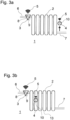
- Fig. 1a shows a heat exchanger system 1 in a first state.
- the heat exchanger system 1 comprises a heat exchanger 2, a thermostat head 3 and a mounting bracket 4.
- the thermostat head 3 and the mounting bracket 4 are adapted to transfer data between each other by means of a data connection unit via a wireless data connection 5.
- the thermostat head 3 is mounted to a heat exchanger input pipe 6.
- the mounting bracket 4 is mounted to a heat exchanger return pipe 7.
- the thermostat head 3 and the mounting bracket 4 are examples for mounting units.
- the heat exchanger system 1 furthermore comprises a temperature sensor arrangement and two electronic relocation detection units 8 being adapted to detect that one or more temperature sensors (not shown in Fig. 1a and 1b ) of the temperature sensor arrangement are relocated relative to the heat exchanger 2.
- Each relocation detection unit 8 is a microprocessor.
- the thermostat head 3 may be removed from the input pipe 6.
- the electronic relocation detection unit 8 arranged in the thermostat head 3 detects that the temperature sensors included in the thermostat head 3 are relocated relative to the heat exchanger 2.
- Another electronic relocation detection unit 8 is in this embodiment included in the mounting bracket 4.
- the electronic relocation detection unit 8 of the thermostat head 3 sends a warning via the wireless data connection 5, in this case to a central data storage server, in order to initiate maintenance and to detect fraud.
- a replacement thermostat head 3 can be installed in order to reinstall the relocated temperature sensors.
- Fig. 2a now shows a thermostat head 3 as it may be, for example, used in the embodiment depicted in Fig. 1a and 1b in more detail.
- the thermostat head 3 comprises a first temperature sensor 9 and a second temperature sensor 10.
- the relocation detection unit 8 is arranged in a common assembly together with the first temperature sensor 9 and the second temperature sensor 10, thus in this case in the thermostat head 3.
- the electronic relocation detection unit 8 is adapted to monitor a change in a first temperature measured by the first temperature sensor 9 and a second temperature measured by the second temperature sensor 10. Furthermore, it is adapted to monitor a temperature difference between the first temperature measured by the first temperature sensor 9 and the second temperature measured by the second temperature sensor 10. When the temperature difference becomes zero, this is taken as an indication that the thermostat head 3 was removed from the heat exchanger inlet pipe 6 together with the first temperature sensor 9 and the second temperature sensor 10, as will be explained in more detail in the following.
- the thermostat head 3 is mounted to a valve housing 11 which itself is mounted to the input pipe 6.
- the thermostat head 3 is adapted to actuate a valve stem 12 in order to actuate a valve element in the valve housing 11. Details are omitted as this function is well known to the person skilled in the art.
- the first temperature sensor 9 is arranged closer to the heat exchanger inlet pipe 6 than the second temperature sensor 10. Specifically, the first temperature sensor 9 is arranged thermally connected to the heat exchanger inlet pipe 6, which is illustrated by the six heat radiation waves emitted from the inlet pipe 6, and the second temperature sensor 10 is arranged more distant from the heat exchanger inlet pipe 6 than the first temperature sensor 9 in order to measure a room temperature. Therefore, a predetermined range of temperature differences is to be expected between the first temperature and the second temperature.
- the electronic relocation detection unit 8 can send a warning so that maintenance may be initiated.
- Fig. 3a and 3b show two states of another embodiment of the heat exchanger system 1.
- the thermostat head 3 includes the first temperature sensor 9 which is thermally connected to a heat exchanger inlet pipe 6.
- the mounting bracket 4 comprises the second temperature sensor 10 being arranged thermally connected to the heat exchanger return pipe 7.
- the thermostat head 3 again comprises the electronic relocation detection unit 8 being adapted to detect whether one or more temperature sensors of the temperature sensor arrangement are relocated relative to the heat exchanger 2.
- the second temperature sensor 10 which shall measure the heat exchanger return temperature at the heat exchanger return pipe 7 is removed from the return pipe 7.
- the electronic relocation detection unit 8 of the thermostat head 3 receives the second temperature via the wireless connection 5, detects a change in the temperature difference between the first temperature sensor 9 and the second temperature sensor 10 and takes this as an indication that the second temperature sensor 10 is dismounted from the return pipe 7. Therefore the relocation detection unit sends a warning via the wireless connection 5.
- Fig. 3b shows a situation in which the mounting bracket 4 is dismounted from the return pipe 7 and mounted to a rib 13 of the heat exchanger 2.
- the electronic relocation detection unit 8 arranged in the thermostat head 3 monitors a temperature response time between the first temperature sensor 9 and the second temperature sensor 10. As in this exemplary embodiment the second temperature sensor 10 was moved closer to the inlet pipe 6, the response time difference between the first temperature sensor 9 and the second temperature sensor 10 decreases. The electronic relocation detection unit 8 detects this decrease in response time and takes this as an indication that the second temperature sensor 10 was moved as furthermore the first temperature remains constant and the second temperature increases. Therefore, a warning is sent via the wireless data connection 5 so that maintenance can be initiated.
- Fig. 4a now shows a further thermostat head 3 for a heat exchanger system 1.
- this thermostat head 3 comprises the first temperature sensor 9 and the relocation detection unit 8. They are integrated in an electronic unit 14 which is adapted to drive a valve actuator element 15 for controlling a fluid flow through the heat exchanger 2.
- the relocation detection unit 8 interprets this as an indication that the first temperature sensor 8 was relocated relative to the heat exchanger 2.
- the electronic relocation detection unit 8 initiates a warning to be sent via the data connection unit of the electronic unit 14 so as to initiate maintenance. It should be understood that instead of sending a warning over the data connection unit also an acoustic or optical warning could be given, for example a warning sound or a warning light emitted by the thermostat head 3.
- Fig. 5a and 5b show a further thermostat head 3 for a heat exchanger system 1.
- the shown thermostat head 3 comprises two batteries 16a, 16b.
- the relocation detection unit 8 is adapted to monitor whether the battery is present in the thermostat head 3.
- the relocation detection unit 8 is not arranged in a common assembly together with one or more of the temperature sensors 9, 10 of the temperature sensor arrangement, like the thermostat head 3 or the mounting bracket 4.
- the heat exchanger system 1 comprises a remote electronic relocation detection unit 8 detecting whether one or more temperature sensors 9, 10 of the temperature sensor arrangement of the heat exchanger system 1 are relocated relative to the heat exchanger 2.
- the electronic relocation detection unit 8 is arranged in a central server in this embodiment.
- the electronic relocation detection unit 8 is adapted to monitor a presence of an electronic signal provided by the data connection unit of the thermostat head 3. As can be seen in Fig. 5b , once the batteries 16a, 16b are removed from the thermostat head 3 the wireless data connection 5 of the thermostat head 3, thus the signal, collapses.
- the electronic relocation detection unit 8 detects that the electronic signal, thus the wireless data connection 5, is absent and takes this as an indication that the temperature sensor 9 of the temperature sensor arrangement was relocated relative to the heat exchanger 2 as the batteries 16a, 16b can only be removed from the thermostat head 3 when the thermostat head 3 and thus the first temperature sensor 9 is relocated relative to the heat exchanger 2 by removing the thermostat head 3 from the valve housing 11.
- the above described embodiments have temperature sensor arrangements comprising only one or two temperature sensors, there are also embodiments with three or more temperature sensors.
- the thermostat head 3 comprises two temperature sensors 9, 10 and at least one additional mounting unit comprises at least one further temperature sensor, like the mounting bracket 4 in Fig. 3a and 3b .
- the temperature difference between temperature sensors 9, 10 is taken as an indicator that one or more temperature sensors 9, 10 of the temperature sensor arrangement are relocated relative to the heat exchanger 2
- the electronic relocation detection unit 8 may monitor the temperature change at the first temperature sensor 9. When the valve is opened so that hot fluid flows into the heat exchanger 2 and the first temperature does not increase, the first temperature sensor 9 must have been tampered with, thus it probably was removed.
- a method for detecting a relocation of the temperature sensor 9, 10 in the heat exchanger system 1 is achieved in which the electronic relocation detection unit 8 detects whether the temperature sensor 9, 10 is relocated relative to the heat exchanger 2.
- This electronic relocation detection function can be reached in different ways, for example by monitoring a temperature change of one or more temperature sensors, like the first temperature sensor 9 and/or the second temperature sensor 10, by monitoring whether a stroke length of the valve actuator element 15 reaches the predetermined stroke length or by monitoring whether the battery 16a, 16b is present in the thermostat head 3 of the heat exchanger system 1, the thermostat head 3 comprising a temperature sensor arrangement.
- the electronic relocation detection unit 8 adapted to detect whether one or more temperature sensors 9, 10 of the temperature sensor arrangement are relocated relative to the heat exchanger 2, as described above, it becomes possible to allow a good setting for the fluid flow through the heat exchanger 2 which is adequately corresponding to the room temperature as it becomes possible to notice in an easy way when the temperature sensor arrangement is tempered. Thus, mismeasurements of the temperature can be detected, maintenance can be initiated accordingly and/or fraud can be detected.
Landscapes
- Engineering & Computer Science (AREA)
- Physics & Mathematics (AREA)
- General Physics & Mathematics (AREA)
- Automation & Control Theory (AREA)
- Remote Sensing (AREA)
- Emergency Alarm Devices (AREA)
- Air Conditioning Control Device (AREA)
Description
- The present invention relates to a heat exchanger system comprising a heat exchanger and a temperature sensor arrangement.
- Furthermore, the present invention relates to a method for detecting a relocation of a temperature sensor in the heat exchanger system.
- From prior art, heat exchanger systems comprising the heat exchanger and the temperature sensor arrangement are known. For example, some heat exchanger systems comprise the heat exchanger having a thermostat head including two temperature sensors, one for monitoring an ambient room temperature and one for monitoring a valve temperature of the heat exchanger. This shall allow a precise setting of heat exchanger temperatures by using temperatures measured by each of the temperature sensors for estimating a room temperature and setting a fluid flow through the heat exchanger accordingly.
- According to
EP 1 645 324 A1 -
US 2013/0081799 A1 discloses a heating system comprising a heating device and a series of room heat exchangers. The room heat exchangers are connected in parallel between a supply line and a return line. Room heat exchanger valves are adjusted using actuators or motor units, and can be limited in each position by stops. The actuators are wirelessly connected or tethered to a central processing unit, which receives and processes data acquired by temperature sensors at a supply point and at a return point of each individual room heat exchanger, respectively. - However, it was found that despite such measures for some heat exchanger systems the setting of the heat exchanger temperature still is not adequate. Sometimes, for example, the fluid flow rate through the heat exchanger remains too low although the heating power provided by the heat exchanger is not adequate at the set flow rate which leads to the room temperature being below a desired level. In other cases, the flow rate is set too high although a desired room temperature is already reached.
- The invention is defined by
independent claims - It is therefore an object of the invention to allow a good setting for the fluid flow through the heat exchanger which is adequately corresponding to the room temperature.
- The object of the invention is solved by the heat exchanger system according to
claim 1. In particular, the heat exchanger system comprises one or more electronic relocation detection units being adapted to detect by monitoring the temperature difference between the first temperature measured by the first temperature sensor and the second temperature measured by the second temperature sensor, whether one or more temperature sensors of the temperature sensor arrangement are relocated relative to the heat exchanger. - The inventors realized that one of the causes for inadequate fluid flow is that temperature sensors of temperature sensor arrangements sometimes become relocated, which may even mean removed, from heat exchanger systems, for example due to vandalism or with the intention to commit billing fraud. This may, for example, be a severe problem in large heating networks with many heat exchangers, like in public buildings, schools, hotels, or the like. Monitoring of each heat exchanger in such a large network can be time consuming and cost intensive.
- Therefore, when the heat exchanger system comprises one or more electronic relocation detection units providing an electronic relocation detection function, monitoring whether one or more of the temperature sensors are relocated can become much easier. That a temperature sensor has been relocated is detected electronically so that the mounting location of the relocated temperature sensor may be readjusted in short time or a replacement temperature sensor may be installed in case the temperature sensor was fully removed. Thus, the room temperature estimate calculated from the temperature sensor measurements will be correct most of the time, leading to a good setting for the fluid flow through the heat exchanger which is adequately corresponding to the room temperature and preventing fraud.
- Preferably, the heat exchanger system comprises a valve element and a valve actuator element. It is preferred that the valve element is arranged in a valve housing. The valve element is preferably arranged at an inlet pipe of the heat exchanger and adapted to control a heating or cooling fluid flow through the heat exchanger. However, in some embodiments the valve element is arranged at an outlet pipe or at a supply pipe which may be located before the inlet or after the outlet pipe, with respect to a fluid flow direction across the heat exchanger. An opening degree of the valve element may be monitored, preferably by the electronic relocation detection unit. In some embodiments, the opening degree may be used by the electronic relocation detection unit in order to detect whether one or more of the temperature sensors of the temperature sensor arrangement are relocated relative to the heat exchanger.
- The temperature sensor arrangement comprises one or more temperature sensors, at least one electronic relocation detection unit being adapted to monitor a temperature change of at least one temperature measured by at least one of the temperature sensors. When hot or cold fluid is supplied via the inlet pipe to the heat exchanger, preferably by opening the valve element to a predetermined opening degree, a change in the temperature, for example an increase or a decrease, in at least one of the temperature sensors of the temperature sensor arrangement is expected. If no such change is detected, the electronic relocation detection unit preferably takes this as an indication that the temperature sensor arrangement was tempered with, thus at least one of the temperature sensors of the temperature sensor arrangement was relocated or removed relative to the heat exchanger.
- In a preferred embodiment of the invention the temperature sensor arrangement comprises a first temperature sensor and a second temperature sensor, at least one electronic relocation detection unit being adapted to monitor a temperature difference between a first temperature measured by the first temperature sensor and a second temperature measured by the second temperature sensor. Monitoring the temperature difference between the first temperature and the second temperature allows to detect when one or both of the first temperature sensor and the second temperature sensor are relocated from their respective predetermined mounting location relative to the heat exchanger as the first temperature and/or the second temperature may change. For example, when the temperature difference changes and reaches a predetermined threshold, the electronic relocation detection unit may take this as an indication that one or both of the first temperature sensor and the second temperature sensor have been relocated. For example, if the temperature difference reaches the predetermined threshold or drops below and one of the first temperature sensor and the second temperature sensor detect the temperature above, for example, 30° C which is well above any expected room temperature, it is likely that both of the temperature sensors are still located on or close to the heat exchanger but have been relocated closer to each other so that their location may need to be adjusted. On the other hand, for example, if the temperature difference reaches or drops below the predetermined threshold and both of the temperature sensors detect a temperature below, for example, 30°C which is well below any expected temperature to be measured directly next to the heat exchanger, it is likely that both, the first temperature sensor and the second temperature sensor, have been completely removed from the heat exchanger and thus need to be replaced.
- The electronic relocation detection unit is preferably adapted to send a warning when the temperature difference reaches or drops below the predetermined threshold. The warning is preferably an optical warning, an acoustical warning or an electrical signal, preferably a voltage output or a current output. The predetermined temperature difference threshold is preferably smaller than 50° C, more preferably smaller than 40° C, more preferably smaller than 30° C, more preferably smaller than 15° C and even more preferably smaller than 5° C. It is most preferred that the predetermined temperature threshold equals 0° C. This is in many embodiments a safe indicator that at least one of the first and the second temperature sensors have been moved as in general no two temperature sensors would show the same temperature when mounted at different predetermined mounting locations in a heat exchanger system. Therefore, when the temperature difference is 0° C, either both sensors are probably mounted at about the same location or both temperature sensors have been removed from the heat exchanger system.
- In some embodiments the electronic relocation detection unit monitors a change of a response time of the temperature difference. For example, if the distance between the first temperature sensor and the second temperature sensor was increased, for example, due to relocating one or both of them, the response time of the temperature difference may increase. In this case, the electronic relocation detection unit may send a warning so that maintenance can be initiated.
- The first temperature sensor is arranged closer to a heat exchanger inlet pipe than the second temperature sensor. It is preferred in some heat exchanger systems to measure an inlet temperature of the heat exchanger. Preferably, the first temperature sensor is arranged to measure the heat exchanger inlet temperature. The second temperature sensor is preferably arranged to detect a temperature different from that of the inlet temperature. Preferably, the second temperature sensor is arranged to measure a room temperature, also called ambient temperature, or a heat exchanger return temperature. The heat exchanger inlet temperature corresponds preferably to a temperature of the fluid flow entering the heat exchanger. The heat exchanger return temperature corresponds preferably to a temperature of the fluid flow leaving the heat exchanger. Measuring the input temperature with the first temperature sensor and a further temperature with the second temperature sensor allows to determine whether the fluid flow through the heat exchanger is adequate in view of the room temperature. Therefore, having the electronic relocation detection unit may be of great use in order to detect whether the temperature sensor arrangement remains in the desired location relative to the heat exchanger. Preferably, the first temperature sensor is mounted to the heat exchanger system by a mounting unit, the mounting unit preferably being a thermostat head. Preferably, the mounting unit includes one or more of at least one temperature sensor of the temperature sensor arrangement, one or more batteries, a data communication unit, the valve actuator, and the electronic relocation detection unit.
- Preferably, the second temperature sensor is arranged thermally connected to a heat exchanger return pipe or arranged to measure a room temperature. Preferably, the second temperature sensor is mounted to the heat exchanger system by means of the mounting unit, preferably a mounting bracket. In some embodiments, the second temperature sensor is mounted to the heat exchanger return pipe by the mounting unit. This allows good measuring of the return temperature of the heat exchanger. In other embodiments, the second temperature sensor is mounted by means of the mounting unit so as to measure the room temperature. The mounting unit may in this case be the thermostat head. Thus, a dedicated mounting unit for the second temperature sensor may be omitted. However, the second temperature sensor may not only be mounted at the return pipe or arranged to measure the room temperature. Other locations, for example, on a surface or a rib of the heat exchanger, are possible as well in some embodiments.
- The first temperature sensor and the second temperature sensor are included in the thermostat head, the first temperature sensor being arranged thermally connected to the heat exchanger inlet pipe and the second temperature sensor being arranged more distant from the heat exchanger inlet pipe than the first temperature sensor. Thus, the first temperature sensor is preferably mounted closer to the heat exchanger inlet pipe than the second temperature sensor. Preferably, the second temperature sensor is arranged at a longitudinal end of the thermostat head more distant from the heat exchanger input pipe than the first temperature sensor. In many heat exchanger systems, the thermostat head can be removed from the heat exchanger rather easily so that having the electronic relocation detection unit detecting whether one or more temperature sensors of the temperature sensor arrangement are relocated together with the thermostat head and relative to the heat exchanger may be very useful when the first temperature sensor and/or the second temperature sensor are included in the thermostat head. In case the electronic relocation detection unit detects that the first temperature sensor and/or the second temperature sensor are removed together with the thermostat head, the electronic relocation detection unit may send a warning, preferably in order to initiate maintenance and/or to detect fraud.
- In another embodiment, the first temperature sensor is included in the thermostat head, the first temperature sensor being arranged thermally connected to the heat exchanger inlet pipe and the second temperature sensor being arranged thermally connected to the heat exchanger return pipe. The second temperature sensor is preferably mounted to the heat exchanger return pipe by means of an additional mounting unit. It is in some embodiments of interest to monitor the temperature difference between heat exchanger inlet and heat exchanger return. For example, a high temperature difference may indicate that the fluid flow needs to be increased. A low temperature difference on the other hand may indicate that the heat transfer between the room in which the heat exchanger system is installed and the heat exchanger needs to be improved. Therefore, it is of importance to monitor the mounting location of inlet temperature sensors and return temperature sensors and to detect by means of one or more electronic relocation detection units whether one or more of the temperature sensors are relocated relative to the heat exchanger. In some embodiments, the inlet temperature and the return temperature shall be measured so as to calculate heat cost allocation for billing of the used heat in, for example, a room or a house. In this situation, it can be extremely important to detect whether one or more of the temperature sensors of the temperature sensor arrangement are relocated relative to the heat exchanger. In some embodiments this is done by the electronic relocation detection unit monitoring the temperature change of at least one temperature measured by at least one of the temperature sensors. In other embodiments, the temperature difference between two temperature sensors is monitored by the electronic relocation detection unit. Both has been described in more detail above already.
- It is preferred that at least one relocation detection unit is adapted to monitor whether a stroke length of the valve actuator element for controlling the fluid flow through the heat exchanger reaches a predetermined stroke length. In some embodiments, the stroke length is used as an indicator whether one or more temperature sensors of the temperature sensor arrangement are relocated relative to the heat exchanger. The valve actuator element is preferably arranged in the thermostat head. A preferred valve actuator element is a spindle. The valve actuator element drives the valve element in the valve housing being preferably arranged at the heat exchanger inlet pipe in order to control the fluid flow through the heat exchanger. Thus, the flow of the heating or cooling fluid may be controlled. When the predetermined stroke length is reached, the electronic relocation detection unit takes this as an indication that the thermostat head is relocated together with the one or more temperature sensors present in the thermostat head. Thus, when the one or more temperature sensors are removed or relocated together with the thermostat head from the heat exchanger, the electronic relocation detection unit will preferably send a warning to notify about the relocation of the temperature sensors. Thus, maintenance may be initiated and/or fraud may be detected.
- Preferably, the predetermined stroke length equals a maximum stroke length. Preferably, the maximum stroke length is only reached when the thermostat head is removed from the valve housing. Therefore, this is a strong indication that the thermostat head is removed together with the one or more temperature sensors in the thermostat head. Thus, when the stroke length reaches 100 %, i.e. maximum, the electronic relocation detection unit may preferably send a warning. Then, maintenance may be initiated. However, in some embodiments the predetermined stroke length may be less than 100 %, preferably less than 90 %, preferably less than 75 %, preferably less than 60 % or preferably less than 50 %. On the other hand, the preferred predetermined stroke length is preferably more than 30 %, preferably more than 40 %, preferably more than 50 %, preferably more than 60 %, preferably more than 70 %, preferably more than 80 %, and most preferably more than 90 % of the maximum stroke length. As long as the predetermined stroke length is unlikely to be reached during normal use of the thermostat head, thus when it is mounted to the heat exchanger, it may be used as an indication for relocation of the thermostat head together with the included temperature sensors when the predetermined stroke length is reached.
- It is preferred that the heat exchanger system comprises the thermostat head for controlling the valve of the heat exchanger, the thermostat head including one or more of the temperature sensors of the temperature sensor arrangement and a battery, at least one electronic relocation detection unit being adapted to monitor if the battery is present in the thermostat head. Some thermostat heads comprise the battery as a power supply. As a removal of the battery often coincides with a relocation or removal of the thermostat head itself, the electronic relocation detection unit may send a warning when an absence of the battery is detected, detecting a relocation of any temperature sensors arranged in the thermostat head together with the thermostat head as well. The detection may be based on mechanical, optical or electronical detection of the presence of the battery. Preferably, the electronic relocation detection unit monitors an electronic signal emitted by the thermostat head. A change in the signal may be taken as an indication that the battery was removed. For example, in some embodiments, the thermostat head stops to emit the signal once the battery is removed. Then the electronic relocation detection unit may interpret the absence of the signal as an indication that the temperature sensor arrangement included in the thermostat head was relocated relative to the heat exchanger.
- In a preferred embodiment, the thermostat head comprises a data connection unit, at least one electronic relocation detection unit being adapted to monitor a presence of an electronic signal provided by the data connection unit. The data connection unit preferably provides a wireless connection between the thermostat head and another element of the heat exchanger system. Preferably, the wireless connection is a Bluetooth connection or a wireless LAN connection. Preferably, temperature data, more preferably the first temperature and/or the second temperature are sent via the data connection unit. For example, the thermostat head may be wirelessly connected to another mounting unit for data transfer and, preferably, vice versa. In some embodiments, the mounting unit is connected to an internet router and/or a central server by the data connection unit. This allows data transfer to a central data storage facility. When the battery is removed, the electronic signal of the wireless connection may vanish as the wireless connection collapses due to a power loss. The relocation detection unit preferably detects the collapse of the wireless signal and sends a warning, preferably over the data connection unit. Based on this, maintenance may be initiated and/or fraud may be detected. Even if the thermostat head and the included temperature sensors are still mounted to the heat exchanger system at least the battery may need to be replaced with a fresh one. In some embodiments, the data connection unit provides a wired data connection instead. Preferably, such a wired data connection is a serial, parallel or LAN-wired connection. Additionally or in the alternative, the mounting unit, preferably for the second temperature sensor, may comprise a wireless or wired data connection unit in order to transfer data, preferably the first temperature and/or the second temperature, preferably to the thermostat head or a central data storage.
- It is preferred that at least one of the electronic relocation detection units is arranged in a common assembly together with one or more temperature sensors of the temperature sensor arrangement. The electronic relocation detection unit is preferably arranged in the mounting unit, preferably in the thermostat head. This allows good integration. Preferably, the electronic relocation detection unit is part of an electronic unit of the mounting unit. Thus, there may be a plurality of electronic relocation detection units in the system when there is a plurality of mounting units. For example, in some embodiments there is one relocation detection unit in each thermostat head and/or one electronic relocation detection unit in each corresponding mounting unit mounted to the same heat exchanger as the thermostat head. This preferably allows to monitor the removal of temperature sensors in the mounting unit, preferably mounted at the heat exchanger outlet pipe, using the relocation detection unit included in the corresponding thermostat head on the same heat exchanger and vice versa. Thus, preferably the thermostat head and the other mounting units mounted to the same heat exchanger are connected to each other via a data connection, preferably a wireless data connection. A preferred relocation detection unit comprises a microprocessor, preferably adapted to perform calculations, preferably on the basis of the first temperature and/or the second temperature. In some embodiments, the relocation detection unit is a microprocessor, embodied as a software on a data carrier, or built from electronic components.
- Furthermore, the object of the invention is solved by a method as described in the outset according to
claim 8, in which an electronic relocation detection function detects by monitoring the temperature difference between the first temperature measured by the first temperature sensor and the second temperature measured by the second temperature sensor, whether the temperature sensor is relocated relative to the heat exchanger. - This allows to detect an unwanted relocation quickly so that the temperature sensor can be reinstalled at its predetermined mounting location. Therefore, a good setting for the fluid flow through the heat exchanger which adequately corresponds to the room temperature becomes possible. In a preferred method, the electronic relocation detection function is provided by the electronic relocation detection unit.
- The method comprises the step of the electronic relocation detection function monitoring a temperature change of at least one temperature sensor. Further preferred features of this method were already described in view of the heat exchanger system further above.
- Preferably, the method comprises the step of the electronic relocation detection function monitoring whether the stroke length of the valve actuator element reaches the predetermined stroke length. Further preferred features were as well already described above with reference to the heat exchanger system.
- It is furthermore preferred that the method comprises the step of the electronic relocation detection function monitoring whether the battery is present in the thermostat head of the heat exchanger system, the thermostat head comprising one or more temperature sensors. Preferred features of this step have as well already been described further above in view of the heat exchanger system.
- In the following the present invention will be described in further detail by means of exemplary embodiments and referring to the attached figures, in which:
- Fig. 1a+1b
- show a heat exchanger system in different states;
- Fig. 2a+2b
- show a thermostat head in an embodiment of the heat exchanger system according to the invention in different states;
- Fig. 3a+3b
- show different states of a heat exchanger system according to another embodiment;
- Fig. 4a+4b
- show another thermostat head in different states; and
- Fig. 5a+5b
- show yet another thermostat head for a heat exchanger system in different states.
- In the following detailed description and the attached patent claims reference signs were introduced. However, it should be understood that the reference signs shall merely improve readability and are in no way meant to be limiting. Furthermore, it should be understood that the given embodiments are schematic examples only and that further embodiments which are not shown may also be covered by the attached set of patent claims. While the following embodiments only show up to two mounting units for temperature sensors, embodiments comprising three or more mounting units are envisaged.
-
Fig. 1a shows aheat exchanger system 1 in a first state. Theheat exchanger system 1 comprises aheat exchanger 2, athermostat head 3 and a mountingbracket 4. Thethermostat head 3 and the mountingbracket 4 are adapted to transfer data between each other by means of a data connection unit via awireless data connection 5. Thethermostat head 3 is mounted to a heatexchanger input pipe 6. The mountingbracket 4 is mounted to a heatexchanger return pipe 7. Thethermostat head 3 and the mountingbracket 4 are examples for mounting units. - The
heat exchanger system 1 furthermore comprises a temperature sensor arrangement and two electronicrelocation detection units 8 being adapted to detect that one or more temperature sensors (not shown inFig. 1a and 1b ) of the temperature sensor arrangement are relocated relative to theheat exchanger 2. Eachrelocation detection unit 8 is a microprocessor. - As shown in
Fig. 1b , thethermostat head 3 may be removed from theinput pipe 6. As thethermostat head 3 in this exemplaric embodiment comprises one or more temperature sensors (not shown inFig. 1a and 1b ), the electronicrelocation detection unit 8 arranged in thethermostat head 3 detects that the temperature sensors included in thethermostat head 3 are relocated relative to theheat exchanger 2. Another electronicrelocation detection unit 8 is in this embodiment included in the mountingbracket 4. When the relocation of the temperature sensors is detected, the electronicrelocation detection unit 8 of thethermostat head 3 sends a warning via thewireless data connection 5, in this case to a central data storage server, in order to initiate maintenance and to detect fraud. Thus, areplacement thermostat head 3 can be installed in order to reinstall the relocated temperature sensors. -
Fig. 2a now shows athermostat head 3 as it may be, for example, used in the embodiment depicted inFig. 1a and 1b in more detail. Thethermostat head 3 comprises afirst temperature sensor 9 and asecond temperature sensor 10. Therelocation detection unit 8 is arranged in a common assembly together with thefirst temperature sensor 9 and thesecond temperature sensor 10, thus in this case in thethermostat head 3. The electronicrelocation detection unit 8 is adapted to monitor a change in a first temperature measured by thefirst temperature sensor 9 and a second temperature measured by thesecond temperature sensor 10. Furthermore, it is adapted to monitor a temperature difference between the first temperature measured by thefirst temperature sensor 9 and the second temperature measured by thesecond temperature sensor 10. When the temperature difference becomes zero, this is taken as an indication that thethermostat head 3 was removed from the heatexchanger inlet pipe 6 together with thefirst temperature sensor 9 and thesecond temperature sensor 10, as will be explained in more detail in the following. - As shown in
Fig. 2a and 2b thethermostat head 3 is mounted to avalve housing 11 which itself is mounted to theinput pipe 6. Thethermostat head 3 is adapted to actuate avalve stem 12 in order to actuate a valve element in thevalve housing 11. Details are omitted as this function is well known to the person skilled in the art. - As can be seen, the
first temperature sensor 9 is arranged closer to the heatexchanger inlet pipe 6 than thesecond temperature sensor 10. Specifically, thefirst temperature sensor 9 is arranged thermally connected to the heatexchanger inlet pipe 6, which is illustrated by the six heat radiation waves emitted from theinlet pipe 6, and thesecond temperature sensor 10 is arranged more distant from the heatexchanger inlet pipe 6 than thefirst temperature sensor 9 in order to measure a room temperature. Therefore, a predetermined range of temperature differences is to be expected between the first temperature and the second temperature. - When the temperature difference falls below a certain threshold, e.g. in this embodiment reaches zero, this is taken as an indication that the
first temperature sensor 9 and thesecond temperature sensor 10 have been relocated relative to theheat exchanger 2, thus that thethermostat head 3 was removed from thevalve housing 11. - This is due to the fact that, as can be understood in view of
Fig. 2b , thefirst temperature sensor 9 will also begin to measure the room temperature once it is more distant from the heatexchanger inlet pipe 6. Thus, the electronicrelocation detection unit 8 can send a warning so that maintenance may be initiated. -
Fig. 3a and 3b show two states of another embodiment of theheat exchanger system 1. In this embodiment, thethermostat head 3 includes thefirst temperature sensor 9 which is thermally connected to a heatexchanger inlet pipe 6. The mountingbracket 4 comprises thesecond temperature sensor 10 being arranged thermally connected to the heatexchanger return pipe 7. Thethermostat head 3 again comprises the electronicrelocation detection unit 8 being adapted to detect whether one or more temperature sensors of the temperature sensor arrangement are relocated relative to theheat exchanger 2. According to
Fig. 3a , thesecond temperature sensor 10 which shall measure the heat exchanger return temperature at the heatexchanger return pipe 7 is removed from thereturn pipe 7. Thus, in this embodiment the electronicrelocation detection unit 8 of thethermostat head 3 receives the second temperature via thewireless connection 5, detects a change in the temperature difference between thefirst temperature sensor 9 and thesecond temperature sensor 10 and takes this as an indication that thesecond temperature sensor 10 is dismounted from thereturn pipe 7. Therefore the relocation detection unit sends a warning via thewireless connection 5. -
Fig. 3b shows a situation in which the mountingbracket 4 is dismounted from thereturn pipe 7 and mounted to arib 13 of theheat exchanger 2. In this exemplary embodiment the electronicrelocation detection unit 8 arranged in thethermostat head 3 monitors a temperature response time between thefirst temperature sensor 9 and thesecond temperature sensor 10. As in this exemplary embodiment thesecond temperature sensor 10 was moved closer to theinlet pipe 6, the response time difference between thefirst temperature sensor 9 and thesecond temperature sensor 10 decreases. The electronicrelocation detection unit 8 detects this decrease in response time and takes this as an indication that thesecond temperature sensor 10 was moved as furthermore the first temperature remains constant and the second temperature increases. Therefore, a warning is sent via thewireless data connection 5 so that maintenance can be initiated. -
Fig. 4a now shows afurther thermostat head 3 for aheat exchanger system 1. Again, thisthermostat head 3 comprises thefirst temperature sensor 9 and therelocation detection unit 8. They are integrated in anelectronic unit 14 which is adapted to drive avalve actuator element 15 for controlling a fluid flow through theheat exchanger 2. As can be seen inFig. 4b , once thethermostat head 3 is removed from the heatexchanger inlet pipe 6 the stroke length of thevalve actuator element 15 becomes a maximum stroke length. Therelocation detection unit 8 interprets this as an indication that thefirst temperature sensor 8 was relocated relative to theheat exchanger 2. Thus, the electronicrelocation detection unit 8 initiates a warning to be sent via the data connection unit of theelectronic unit 14 so as to initiate maintenance. It should be understood that instead of sending a warning over the data connection unit also an acoustic or optical warning could be given, for example a warning sound or a warning light emitted by thethermostat head 3. -
Fig. 5a and 5b show afurther thermostat head 3 for aheat exchanger system 1. The shownthermostat head 3 comprises twobatteries relocation detection unit 8 is adapted to monitor whether the battery is present in thethermostat head 3. In this embodiment, therelocation detection unit 8 is not arranged in a common assembly together with one or more of thetemperature sensors thermostat head 3 or the mountingbracket 4. Instead, theheat exchanger system 1 comprises a remote electronicrelocation detection unit 8 detecting whether one ormore temperature sensors heat exchanger system 1 are relocated relative to theheat exchanger 2. The electronicrelocation detection unit 8 is arranged in a central server in this embodiment. - Specifically, the electronic
relocation detection unit 8 is adapted to monitor a presence of an electronic signal provided by the data connection unit of thethermostat head 3. As can be seen inFig. 5b , once thebatteries thermostat head 3 thewireless data connection 5 of thethermostat head 3, thus the signal, collapses. The electronicrelocation detection unit 8 detects that the electronic signal, thus thewireless data connection 5, is absent and takes this as an indication that thetemperature sensor 9 of the temperature sensor arrangement was relocated relative to theheat exchanger 2 as thebatteries thermostat head 3 when thethermostat head 3 and thus thefirst temperature sensor 9 is relocated relative to theheat exchanger 2 by removing thethermostat head 3 from thevalve housing 11. - Although the above described embodiments have temperature sensor arrangements comprising only one or two temperature sensors, there are also embodiments with three or more temperature sensors. For example, there may then be one or two temperature sensors in the
thermostat head 3, as described above, and additional temperature sensors in further mounting units at thesame heat exchanger 2. In preferred embodiments, thethermostat head 3 comprises twotemperature sensors bracket 4 inFig. 3a and 3b . - Furthermore, while in the above described embodiments the temperature difference between
temperature sensors more temperature sensors heat exchanger 2, there are embodiments which are not shown in which only the temperature change of one or more temperature sensors is monitored by the electronicrelocation detection unit 8 to detect whether one ormore temperature sensors heat exchanger 2. For example, the electronicrelocation detection unit 8 may monitor the temperature change at thefirst temperature sensor 9. When the valve is opened so that hot fluid flows into theheat exchanger 2 and the first temperature does not increase, thefirst temperature sensor 9 must have been tampered with, thus it probably was removed. - Thus, it becomes clear that according to the invention a method for detecting a relocation of the
temperature sensor heat exchanger system 1 is achieved in which the electronicrelocation detection unit 8 detects whether thetemperature sensor heat exchanger 2. This electronic relocation detection function can be reached in different ways, for example by monitoring a temperature change of one or more temperature sensors, like thefirst temperature sensor 9 and/or thesecond temperature sensor 10, by monitoring whether a stroke length of thevalve actuator element 15 reaches the predetermined stroke length or by monitoring whether thebattery thermostat head 3 of theheat exchanger system 1, thethermostat head 3 comprising a temperature sensor arrangement. - By having the electronic
relocation detection unit 8 adapted to detect whether one ormore temperature sensors heat exchanger 2, as described above, it becomes possible to allow a good setting for the fluid flow through theheat exchanger 2 which is adequately corresponding to the room temperature as it becomes possible to notice in an easy way when the temperature sensor arrangement is tempered. Thus, mismeasurements of the temperature can be detected, maintenance can be initiated accordingly and/or fraud can be detected.
Claims (10)
- A heat exchanger system (1) comprising a heat exchanger (2) and a temperature sensor arrangement,wherein the temperature sensor arrangement comprises a first temperature sensor (9) and a second temperature sensor (10), at least one electronic relocation detection unit (8) being adapted to monitor a temperature change of at least one temperature measured by at least one of the temperature sensors (9, 10), wherein the temperature sensor measurements lead to a setting for the flow through the heat exchanger,wherein the first temperature sensor (9) is arranged thermally connected to a heat exchanger inlet pipe (6) and is arranged closer to the heat exchanger inlet pipe (6) than a second temperature sensor (10) and wherein the second temperature sensor (10) is arranged more distant from the heat exchanger inlet pipe (6) than the first temperature sensor (9),wherein the first temperature sensor (9) and the second temperature sensor (10) are included in a thermostat head (3),characterized in that the heat exchanger system comprises one or more electronic relocation detection units (8) being adapted to detect by monitoring the temperature difference between the first temperature measured by the first temperature sensor (9) and the second temperature measured by the second temperature sensor (10), whether the temperature sensors (9, 10) of the temperature sensor arrangement are relocated relative to the heat exchanger (2).
- The heat exchanger system according to claim 1, wherein the second temperature sensor (10) is arranged to measure a room temperature.
- The heat exchanger system according to claim 1 or 2, characterized in that the at least one electronic relocation detection unit (8) is adapted to monitor whether a stroke length of a valve actuator element (15) for controlling a fluid flow through the heat exchanger (2) reaches a predetermined stroke length.
- The heat exchanger system according to claim 3, characterized in that the predetermined stroke length equals a maximum stroke length.
- The heat exchanger system according to any of the claims 1 to 4, characterized by the thermostat head (3) for controlling a valve of the heat exchanger (2), the thermostat head (3) further including a battery (16a, 16b), at least one electronic relocation detection unit (8) being adapted to monitor whether the battery is present in the thermostat head (3).
- The heat exchanger system according to claim 5, characterized in that the thermostat head (3) comprises a data connection unit, the at least one electronic relocation detection unit (8) being adapted to monitor a presence of an electronic signal (5) provided by the data connection unit.
- The heat exchanger system according to any of the claims 1 to 6, characterized in that the at least one electronic relocation detection unit (8) is arranged in a common assembly together with one or more of the temperature sensors (9, 10) of the temperature sensor arrangement.
- A method for detecting a relocation of a temperature sensor (9, 10) in a heat exchanger system (1) comprising a heat exchanger (2) and a temperature sensor arrangement, which comprises a first temperature sensor (9), a second temperature sensor (10), and at least one electronic relocation detection unit (8), wherein the first temperature sensor (9) is arranged thermally connected to a heat exchanger inlet pipe (6) and is arranged closer to the heat exchanger inlet pipe (6) than a second temperature sensor (10) and wherein the second temperature sensor (10) is arranged more distant from the heat exchanger inlet pipe (6) than the first temperature sensor (9), wherein the temperature sensor measurements lead to a setting for the flow through the heat exchanger,
comprising the steps of:monitoring a temperature change of at least one temperature measured by at least one of the temperature sensors (9, 10) with the at least one electronic relocation detection unit (8),wherein the temperature sensor measurements lead to a setting for the flow through the heat exchanger,wherein the first temperature sensor (9) and the second temperature sensor (10) are included in a thermostat head (3).characterized in that an electronic relocation detection function detects by monitoring the temperature difference between the first temperature measured by the first temperature sensor (9) and the second temperature measured by the second temperature sensor (10), whether one or more temperature sensors (9, 10) of the temperature sensor arrangement are relocated relative to the heat exchanger (2). - The method according to claim 8, characterized by the step of the electronic relocation detection function monitoring whether a stroke length of a valve actuator element (15) reaches a predetermined stroke length.
- The method according to claim 8 or 9, characterized by the step of the electronic relocation detection function monitoring whether a battery is present in a thermostat head (3) of the heat exchanger system (2), the thermostat head (3) comprising a temperature sensors arrangement.
Priority Applications (3)
| Application Number | Priority Date | Filing Date | Title |
|---|---|---|---|
| DK16183491.6T DK3282337T4 (en) | 2016-08-10 | 2016-08-10 | Heat exchanger system and method for detecting a relocation of a temperature sensor in a heat exchanger system |
| PL16183491.6T PL3282337T5 (en) | 2016-08-10 | 2016-08-10 | Heat exchanger system and method for detecting a relocation of a temperature sensor in a heat exchanger system |
| EP16183491.6A EP3282337B2 (en) | 2016-08-10 | 2016-08-10 | Heat exchanger system and method for detecting a relocation of a temperature sensor in a heat exchanger system |
Applications Claiming Priority (1)
| Application Number | Priority Date | Filing Date | Title |
|---|---|---|---|
| EP16183491.6A EP3282337B2 (en) | 2016-08-10 | 2016-08-10 | Heat exchanger system and method for detecting a relocation of a temperature sensor in a heat exchanger system |
Publications (3)
| Publication Number | Publication Date |
|---|---|
| EP3282337A1 EP3282337A1 (en) | 2018-02-14 |
| EP3282337B1 EP3282337B1 (en) | 2020-01-15 |
| EP3282337B2 true EP3282337B2 (en) | 2023-05-24 |
Family
ID=56800150
Family Applications (1)
| Application Number | Title | Priority Date | Filing Date |
|---|---|---|---|
| EP16183491.6A Active EP3282337B2 (en) | 2016-08-10 | 2016-08-10 | Heat exchanger system and method for detecting a relocation of a temperature sensor in a heat exchanger system |
Country Status (3)
| Country | Link |
|---|---|
| EP (1) | EP3282337B2 (en) |
| DK (1) | DK3282337T4 (en) |
| PL (1) | PL3282337T5 (en) |
Families Citing this family (1)
| Publication number | Priority date | Publication date | Assignee | Title |
|---|---|---|---|---|
| SK10179Y1 (en) | 2024-02-12 | 2024-11-06 | Amicus Sk, S.R.O. | Heating element valve head, heating control system and method therefor |
Citations (14)
| Publication number | Priority date | Publication date | Assignee | Title |
|---|---|---|---|---|
| DE3704778A1 (en) † | 1987-02-16 | 1987-10-08 | Ruediger Gilde | Combined electromechanical electronic heating measurement process for consumption-proportional breakdown of the heating costs in dwellings occupied by more than one family |
| DE4025323A1 (en) † | 1990-08-10 | 1992-02-13 | Oventrop Sohn Kg F W | Throughflow measurer for radiators of central heating system - has electronic computer receiving measurement values from length and pressure differential measuring units |
| DE19749623A1 (en) † | 1996-11-11 | 1998-05-14 | Rettig Laempoe Oy | Control unit for central heating radiator with liquid circulation |
| DE29710248U1 (en) † | 1997-06-12 | 1998-10-15 | Raab Karcher Energy Services GmbH, 45131 Essen | Device for recording heat consumption and for regulating the heating power of a single radiator for room temperature control |
| EP1158250B1 (en) † | 2000-05-20 | 2004-11-24 | Techem Energy Services GmbH & Co. KG | Apparatus for detecting the heat output of a radiator and regulating the room temperature |
| DE102004020292B3 (en) † | 2004-04-26 | 2005-12-01 | Danfoss A/S | Heater unit or radiator arrangement with analysis unit releasably fastened to a connector unit |
| EP1645324A1 (en) † | 2004-10-11 | 2006-04-12 | Ford Global Technologies, LLC | Anti tampering arrangement and method for detecting tampering with a device |
| US20070018830A1 (en) † | 2005-07-20 | 2007-01-25 | Honda Motor Co., Ltd. | Vehicle component tamper detection system |
| EP2068138A2 (en) † | 2007-12-07 | 2009-06-10 | Ista International GmbH | Method and device for recording the heat given off by a heating surface |
| EP2442038A2 (en) † | 2010-10-13 | 2012-04-18 | Mondial Tecno S.r.l. | Integrated apparatus for metering the heat supplied by radiators and for controlling a thermostatic valve |
| US20130081799A1 (en) † | 2010-06-09 | 2013-04-04 | Loeblich & Huebner Energie-Effizienz Und Haustechnik Gmbh | Method for setting the volumetric flow rate of a heating and/or cooling medium by means of room heat exchangers of a heating or cooling system |
| US20140100673A1 (en) † | 2012-10-05 | 2014-04-10 | Fisher Controls International Llc | Methods and Apparatus for Process Device Calibration |
| US20150187194A1 (en) † | 2013-12-29 | 2015-07-02 | Keanu Hypolite | Device, system, and method of smoke and hazard detection |
| DE202016101631U1 (en) † | 2016-03-08 | 2016-04-18 | Techem Energy Services Gmbh | Heat cost allocator for detecting the amount of heat emitted by a radiator |
-
2016
- 2016-08-10 DK DK16183491.6T patent/DK3282337T4/en active
- 2016-08-10 EP EP16183491.6A patent/EP3282337B2/en active Active
- 2016-08-10 PL PL16183491.6T patent/PL3282337T5/en unknown
Patent Citations (14)
| Publication number | Priority date | Publication date | Assignee | Title |
|---|---|---|---|---|
| DE3704778A1 (en) † | 1987-02-16 | 1987-10-08 | Ruediger Gilde | Combined electromechanical electronic heating measurement process for consumption-proportional breakdown of the heating costs in dwellings occupied by more than one family |
| DE4025323A1 (en) † | 1990-08-10 | 1992-02-13 | Oventrop Sohn Kg F W | Throughflow measurer for radiators of central heating system - has electronic computer receiving measurement values from length and pressure differential measuring units |
| DE19749623A1 (en) † | 1996-11-11 | 1998-05-14 | Rettig Laempoe Oy | Control unit for central heating radiator with liquid circulation |
| DE29710248U1 (en) † | 1997-06-12 | 1998-10-15 | Raab Karcher Energy Services GmbH, 45131 Essen | Device for recording heat consumption and for regulating the heating power of a single radiator for room temperature control |
| EP1158250B1 (en) † | 2000-05-20 | 2004-11-24 | Techem Energy Services GmbH & Co. KG | Apparatus for detecting the heat output of a radiator and regulating the room temperature |
| DE102004020292B3 (en) † | 2004-04-26 | 2005-12-01 | Danfoss A/S | Heater unit or radiator arrangement with analysis unit releasably fastened to a connector unit |
| EP1645324A1 (en) † | 2004-10-11 | 2006-04-12 | Ford Global Technologies, LLC | Anti tampering arrangement and method for detecting tampering with a device |
| US20070018830A1 (en) † | 2005-07-20 | 2007-01-25 | Honda Motor Co., Ltd. | Vehicle component tamper detection system |
| EP2068138A2 (en) † | 2007-12-07 | 2009-06-10 | Ista International GmbH | Method and device for recording the heat given off by a heating surface |
| US20130081799A1 (en) † | 2010-06-09 | 2013-04-04 | Loeblich & Huebner Energie-Effizienz Und Haustechnik Gmbh | Method for setting the volumetric flow rate of a heating and/or cooling medium by means of room heat exchangers of a heating or cooling system |
| EP2442038A2 (en) † | 2010-10-13 | 2012-04-18 | Mondial Tecno S.r.l. | Integrated apparatus for metering the heat supplied by radiators and for controlling a thermostatic valve |
| US20140100673A1 (en) † | 2012-10-05 | 2014-04-10 | Fisher Controls International Llc | Methods and Apparatus for Process Device Calibration |
| US20150187194A1 (en) † | 2013-12-29 | 2015-07-02 | Keanu Hypolite | Device, system, and method of smoke and hazard detection |
| DE202016101631U1 (en) † | 2016-03-08 | 2016-04-18 | Techem Energy Services Gmbh | Heat cost allocator for detecting the amount of heat emitted by a radiator |
Non-Patent Citations (1)
| Title |
|---|
| DIN EN 834: 2013-13, 2013 † |
Also Published As
| Publication number | Publication date |
|---|---|
| EP3282337B1 (en) | 2020-01-15 |
| DK3282337T4 (en) | 2024-03-11 |
| EP3282337A1 (en) | 2018-02-14 |
| PL3282337T5 (en) | 2023-09-18 |
| DK3282337T3 (en) | 2020-03-30 |
| PL3282337T3 (en) | 2020-06-29 |
Similar Documents
| Publication | Publication Date | Title |
|---|---|---|
| JP6194410B2 (en) | Monitoring system | |
| US9631833B2 (en) | Climate control systems, and methods relating thereto | |
| EP3543710B1 (en) | Power efficient heater control of air data sensor | |
| EP2843500B1 (en) | Oil cooling device for server and method for driving same | |
| US7548170B1 (en) | Rear door heat exchanger instrumentation for heat quantity measurement | |
| CN104406453B (en) | The control device of condenser on-line cleaning equipment and control method and central air-conditioning | |
| EP2950626B1 (en) | Error detection system for cooling apparatus | |
| CN105026868A (en) | Method for Airflow Failure and Cause Identification | |
| CN103870379A (en) | Fan abnormity alarming system and method | |
| JP2015226407A5 (en) | ||
| EP3282337B1 (en) | Heat exchanger system and method for detecting a relocation of a temperature sensor in a heat exchanger system | |
| US10712222B2 (en) | Air pressure and temperature measurement system | |
| CN108885022A (en) | Air-conditioning blows out temperature estimation rneans and program | |
| CN107143904B (en) | Continuous water supply type room heating temperature control and heat metering device and method | |
| JP2010007569A (en) | Cooling judgment method for engine and judgment system thereof | |
| KR101747835B1 (en) | Remote server | |
| US20180119845A1 (en) | Sensor connection structure | |
| CN100480589C (en) | Radiator | |
| JP4765798B2 (en) | Diagnostic device and air conditioning management device | |
| US11730991B2 (en) | Sprinkler self-diagnosis | |
| KR20170069802A (en) | Control system for cooling fan and control method using the same | |
| KR20160074770A (en) | Air Condition System for Data Center and Sever Rack Mountable Temperature-Humidity Sensor thereof | |
| CN110067636A (en) | A kind of vehicle cooling system early warning system and method | |
| JP2005309724A (en) | Abnormality diagnosis system and abnormality diagnosis method | |
| JP4547312B2 (en) | Temperature sensor and fire detector |
Legal Events
| Date | Code | Title | Description |
|---|---|---|---|
| PUAI | Public reference made under article 153(3) epc to a published international application that has entered the european phase |
Free format text: ORIGINAL CODE: 0009012 |
|
| STAA | Information on the status of an ep patent application or granted ep patent |
Free format text: STATUS: THE APPLICATION HAS BEEN PUBLISHED |
|
| AK | Designated contracting states |
Kind code of ref document: A1 Designated state(s): AL AT BE BG CH CY CZ DE DK EE ES FI FR GB GR HR HU IE IS IT LI LT LU LV MC MK MT NL NO PL PT RO RS SE SI SK SM TR |
|
| AX | Request for extension of the european patent |
Extension state: BA ME |
|
| STAA | Information on the status of an ep patent application or granted ep patent |
Free format text: STATUS: REQUEST FOR EXAMINATION WAS MADE |
|
| 17P | Request for examination filed |
Effective date: 20180810 |
|
| RBV | Designated contracting states (corrected) |
Designated state(s): AL AT BE BG CH CY CZ DE DK EE ES FI FR GB GR HR HU IE IS IT LI LT LU LV MC MK MT NL NO PL PT RO RS SE SI SK SM TR |
|
| STAA | Information on the status of an ep patent application or granted ep patent |
Free format text: STATUS: EXAMINATION IS IN PROGRESS |
|
| 17Q | First examination report despatched |
Effective date: 20190102 |
|
| GRAP | Despatch of communication of intention to grant a patent |
Free format text: ORIGINAL CODE: EPIDOSNIGR1 |
|
| STAA | Information on the status of an ep patent application or granted ep patent |
Free format text: STATUS: GRANT OF PATENT IS INTENDED |
|
| INTG | Intention to grant announced |
Effective date: 20190906 |
|
| GRAS | Grant fee paid |
Free format text: ORIGINAL CODE: EPIDOSNIGR3 |
|
| GRAA | (expected) grant |
Free format text: ORIGINAL CODE: 0009210 |
|
| STAA | Information on the status of an ep patent application or granted ep patent |
Free format text: STATUS: THE PATENT HAS BEEN GRANTED |
|
| AK | Designated contracting states |
Kind code of ref document: B1 Designated state(s): AL AT BE BG CH CY CZ DE DK EE ES FI FR GB GR HR HU IE IS IT LI LT LU LV MC MK MT NL NO PL PT RO RS SE SI SK SM TR |
|
| REG | Reference to a national code |
Ref country code: CH Ref legal event code: EP Ref country code: GB Ref legal event code: FG4D |
|
| REG | Reference to a national code |
Ref country code: IE Ref legal event code: FG4D |
|
| REG | Reference to a national code |
Ref country code: DE Ref legal event code: R096 Ref document number: 602016028182 Country of ref document: DE |
|
| REG | Reference to a national code |
Ref country code: AT Ref legal event code: REF Ref document number: 1225710 Country of ref document: AT Kind code of ref document: T Effective date: 20200215 |
|
| REG | Reference to a national code |
Ref country code: DK Ref legal event code: T3 Effective date: 20200327 |
|
| REG | Reference to a national code |
Ref country code: NL Ref legal event code: MP Effective date: 20200115 |
|
| REG | Reference to a national code |
Ref country code: LT Ref legal event code: MG4D |
|
| PG25 | Lapsed in a contracting state [announced via postgrant information from national office to epo] |
Ref country code: RS Free format text: LAPSE BECAUSE OF FAILURE TO SUBMIT A TRANSLATION OF THE DESCRIPTION OR TO PAY THE FEE WITHIN THE PRESCRIBED TIME-LIMIT Effective date: 20200115 Ref country code: PT Free format text: LAPSE BECAUSE OF FAILURE TO SUBMIT A TRANSLATION OF THE DESCRIPTION OR TO PAY THE FEE WITHIN THE PRESCRIBED TIME-LIMIT Effective date: 20200607 Ref country code: NO Free format text: LAPSE BECAUSE OF FAILURE TO SUBMIT A TRANSLATION OF THE DESCRIPTION OR TO PAY THE FEE WITHIN THE PRESCRIBED TIME-LIMIT Effective date: 20200415 Ref country code: FI Free format text: LAPSE BECAUSE OF FAILURE TO SUBMIT A TRANSLATION OF THE DESCRIPTION OR TO PAY THE FEE WITHIN THE PRESCRIBED TIME-LIMIT Effective date: 20200115 Ref country code: NL Free format text: LAPSE BECAUSE OF FAILURE TO SUBMIT A TRANSLATION OF THE DESCRIPTION OR TO PAY THE FEE WITHIN THE PRESCRIBED TIME-LIMIT Effective date: 20200115 |
|
| PG25 | Lapsed in a contracting state [announced via postgrant information from national office to epo] |
Ref country code: SE Free format text: LAPSE BECAUSE OF FAILURE TO SUBMIT A TRANSLATION OF THE DESCRIPTION OR TO PAY THE FEE WITHIN THE PRESCRIBED TIME-LIMIT Effective date: 20200115 Ref country code: LV Free format text: LAPSE BECAUSE OF FAILURE TO SUBMIT A TRANSLATION OF THE DESCRIPTION OR TO PAY THE FEE WITHIN THE PRESCRIBED TIME-LIMIT Effective date: 20200115 Ref country code: HR Free format text: LAPSE BECAUSE OF FAILURE TO SUBMIT A TRANSLATION OF THE DESCRIPTION OR TO PAY THE FEE WITHIN THE PRESCRIBED TIME-LIMIT Effective date: 20200115 Ref country code: GR Free format text: LAPSE BECAUSE OF FAILURE TO SUBMIT A TRANSLATION OF THE DESCRIPTION OR TO PAY THE FEE WITHIN THE PRESCRIBED TIME-LIMIT Effective date: 20200416 Ref country code: BG Free format text: LAPSE BECAUSE OF FAILURE TO SUBMIT A TRANSLATION OF THE DESCRIPTION OR TO PAY THE FEE WITHIN THE PRESCRIBED TIME-LIMIT Effective date: 20200415 Ref country code: IS Free format text: LAPSE BECAUSE OF FAILURE TO SUBMIT A TRANSLATION OF THE DESCRIPTION OR TO PAY THE FEE WITHIN THE PRESCRIBED TIME-LIMIT Effective date: 20200515 |
|
| REG | Reference to a national code |
Ref country code: DE Ref legal event code: R026 Ref document number: 602016028182 Country of ref document: DE |
|
| PLBI | Opposition filed |
Free format text: ORIGINAL CODE: 0009260 |
|
| PLAX | Notice of opposition and request to file observation + time limit sent |
Free format text: ORIGINAL CODE: EPIDOSNOBS2 |
|
| PG25 | Lapsed in a contracting state [announced via postgrant information from national office to epo] |
Ref country code: SK Free format text: LAPSE BECAUSE OF FAILURE TO SUBMIT A TRANSLATION OF THE DESCRIPTION OR TO PAY THE FEE WITHIN THE PRESCRIBED TIME-LIMIT Effective date: 20200115 Ref country code: RO Free format text: LAPSE BECAUSE OF FAILURE TO SUBMIT A TRANSLATION OF THE DESCRIPTION OR TO PAY THE FEE WITHIN THE PRESCRIBED TIME-LIMIT Effective date: 20200115 Ref country code: CZ Free format text: LAPSE BECAUSE OF FAILURE TO SUBMIT A TRANSLATION OF THE DESCRIPTION OR TO PAY THE FEE WITHIN THE PRESCRIBED TIME-LIMIT Effective date: 20200115 Ref country code: ES Free format text: LAPSE BECAUSE OF FAILURE TO SUBMIT A TRANSLATION OF THE DESCRIPTION OR TO PAY THE FEE WITHIN THE PRESCRIBED TIME-LIMIT Effective date: 20200115 Ref country code: LT Free format text: LAPSE BECAUSE OF FAILURE TO SUBMIT A TRANSLATION OF THE DESCRIPTION OR TO PAY THE FEE WITHIN THE PRESCRIBED TIME-LIMIT Effective date: 20200115 Ref country code: SM Free format text: LAPSE BECAUSE OF FAILURE TO SUBMIT A TRANSLATION OF THE DESCRIPTION OR TO PAY THE FEE WITHIN THE PRESCRIBED TIME-LIMIT Effective date: 20200115 Ref country code: EE Free format text: LAPSE BECAUSE OF FAILURE TO SUBMIT A TRANSLATION OF THE DESCRIPTION OR TO PAY THE FEE WITHIN THE PRESCRIBED TIME-LIMIT Effective date: 20200115 |
|
| REG | Reference to a national code |
Ref country code: AT Ref legal event code: MK05 Ref document number: 1225710 Country of ref document: AT Kind code of ref document: T Effective date: 20200115 |
|
| 26 | Opposition filed |
Opponent name: TECHEM ENERGY SERVICES GMBH Effective date: 20201015 |
|
| PLBB | Reply of patent proprietor to notice(s) of opposition received |
Free format text: ORIGINAL CODE: EPIDOSNOBS3 |
|
| PG25 | Lapsed in a contracting state [announced via postgrant information from national office to epo] |
Ref country code: AT Free format text: LAPSE BECAUSE OF FAILURE TO SUBMIT A TRANSLATION OF THE DESCRIPTION OR TO PAY THE FEE WITHIN THE PRESCRIBED TIME-LIMIT Effective date: 20200115 Ref country code: IT Free format text: LAPSE BECAUSE OF FAILURE TO SUBMIT A TRANSLATION OF THE DESCRIPTION OR TO PAY THE FEE WITHIN THE PRESCRIBED TIME-LIMIT Effective date: 20200115 |
|
| PG25 | Lapsed in a contracting state [announced via postgrant information from national office to epo] |
Ref country code: SI Free format text: LAPSE BECAUSE OF FAILURE TO SUBMIT A TRANSLATION OF THE DESCRIPTION OR TO PAY THE FEE WITHIN THE PRESCRIBED TIME-LIMIT Effective date: 20200115 |
|
| PG25 | Lapsed in a contracting state [announced via postgrant information from national office to epo] |
Ref country code: MC Free format text: LAPSE BECAUSE OF FAILURE TO SUBMIT A TRANSLATION OF THE DESCRIPTION OR TO PAY THE FEE WITHIN THE PRESCRIBED TIME-LIMIT Effective date: 20200115 |
|
| PG25 | Lapsed in a contracting state [announced via postgrant information from national office to epo] |
Ref country code: LU Free format text: LAPSE BECAUSE OF NON-PAYMENT OF DUE FEES Effective date: 20200810 |
|
| REG | Reference to a national code |
Ref country code: BE Ref legal event code: MM Effective date: 20200831 |
|
| PG25 | Lapsed in a contracting state [announced via postgrant information from national office to epo] |
Ref country code: IE Free format text: LAPSE BECAUSE OF NON-PAYMENT OF DUE FEES Effective date: 20200810 Ref country code: BE Free format text: LAPSE BECAUSE OF NON-PAYMENT OF DUE FEES Effective date: 20200831 |
|
| PG25 | Lapsed in a contracting state [announced via postgrant information from national office to epo] |
Ref country code: TR Free format text: LAPSE BECAUSE OF FAILURE TO SUBMIT A TRANSLATION OF THE DESCRIPTION OR TO PAY THE FEE WITHIN THE PRESCRIBED TIME-LIMIT Effective date: 20200115 Ref country code: MT Free format text: LAPSE BECAUSE OF FAILURE TO SUBMIT A TRANSLATION OF THE DESCRIPTION OR TO PAY THE FEE WITHIN THE PRESCRIBED TIME-LIMIT Effective date: 20200115 Ref country code: CY Free format text: LAPSE BECAUSE OF FAILURE TO SUBMIT A TRANSLATION OF THE DESCRIPTION OR TO PAY THE FEE WITHIN THE PRESCRIBED TIME-LIMIT Effective date: 20200115 |
|
| APBM | Appeal reference recorded |
Free format text: ORIGINAL CODE: EPIDOSNREFNO |
|
| APBP | Date of receipt of notice of appeal recorded |
Free format text: ORIGINAL CODE: EPIDOSNNOA2O |
|
| APAH | Appeal reference modified |
Free format text: ORIGINAL CODE: EPIDOSCREFNO |
|
| PG25 | Lapsed in a contracting state [announced via postgrant information from national office to epo] |
Ref country code: MK Free format text: LAPSE BECAUSE OF FAILURE TO SUBMIT A TRANSLATION OF THE DESCRIPTION OR TO PAY THE FEE WITHIN THE PRESCRIBED TIME-LIMIT Effective date: 20200115 Ref country code: AL Free format text: LAPSE BECAUSE OF FAILURE TO SUBMIT A TRANSLATION OF THE DESCRIPTION OR TO PAY THE FEE WITHIN THE PRESCRIBED TIME-LIMIT Effective date: 20200115 |
|
| APBU | Appeal procedure closed |
Free format text: ORIGINAL CODE: EPIDOSNNOA9O |
|
| PUAH | Patent maintained in amended form |
Free format text: ORIGINAL CODE: 0009272 |
|
| STAA | Information on the status of an ep patent application or granted ep patent |
Free format text: STATUS: PATENT MAINTAINED AS AMENDED |
|
| 27A | Patent maintained in amended form |
Effective date: 20230524 |
|
| AK | Designated contracting states |
Kind code of ref document: B2 Designated state(s): AL AT BE BG CH CY CZ DE DK EE ES FI FR GB GR HR HU IE IS IT LI LT LU LV MC MK MT NL NO PL PT RO RS SE SI SK SM TR |
|
| REG | Reference to a national code |
Ref country code: DE Ref legal event code: R102 Ref document number: 602016028182 Country of ref document: DE |
|
| P01 | Opt-out of the competence of the unified patent court (upc) registered |
Effective date: 20230617 |
|
| PG25 | Lapsed in a contracting state [announced via postgrant information from national office to epo] |
Ref country code: DK Free format text: LAPSE BECAUSE OF FAILURE TO SUBMIT A TRANSLATION OF THE DESCRIPTION OR TO PAY THE FEE WITHIN THE PRESCRIBED TIME-LIMIT Effective date: 20230524 |
|
| REG | Reference to a national code |
Ref country code: DK Ref legal event code: T4 Effective date: 20240308 |
|
| PGFP | Annual fee paid to national office [announced via postgrant information from national office to epo] |
Ref country code: DE Payment date: 20240702 Year of fee payment: 9 |
|
| PG2D | Information on lapse in contracting state deleted |
Ref country code: DK |
|
| PGFP | Annual fee paid to national office [announced via postgrant information from national office to epo] |
Ref country code: DK Payment date: 20240813 Year of fee payment: 9 |
|
| PGFP | Annual fee paid to national office [announced via postgrant information from national office to epo] |
Ref country code: GB Payment date: 20240701 Year of fee payment: 9 |
|
| PGFP | Annual fee paid to national office [announced via postgrant information from national office to epo] |
Ref country code: FR Payment date: 20240726 Year of fee payment: 9 |
|
| PGFP | Annual fee paid to national office [announced via postgrant information from national office to epo] |
Ref country code: CH Payment date: 20240901 Year of fee payment: 9 |
|
| PGFP | Annual fee paid to national office [announced via postgrant information from national office to epo] |
Ref country code: PL Payment date: 20240716 Year of fee payment: 9 |