EP3282282A1 - Occupancy detection apparatus and method for controlling the same - Google Patents
Occupancy detection apparatus and method for controlling the same Download PDFInfo
- Publication number
- EP3282282A1 EP3282282A1 EP17185315.3A EP17185315A EP3282282A1 EP 3282282 A1 EP3282282 A1 EP 3282282A1 EP 17185315 A EP17185315 A EP 17185315A EP 3282282 A1 EP3282282 A1 EP 3282282A1
- Authority
- EP
- European Patent Office
- Prior art keywords
- signal
- reception antenna
- occupancy detection
- detection apparatus
- reflected
- Prior art date
- Legal status (The legal status is an assumption and is not a legal conclusion. Google has not performed a legal analysis and makes no representation as to the accuracy of the status listed.)
- Withdrawn
Links
Images






Classifications
-
- G—PHYSICS
- G01—MEASURING; TESTING
- G01S—RADIO DIRECTION-FINDING; RADIO NAVIGATION; DETERMINING DISTANCE OR VELOCITY BY USE OF RADIO WAVES; LOCATING OR PRESENCE-DETECTING BY USE OF THE REFLECTION OR RERADIATION OF RADIO WAVES; ANALOGOUS ARRANGEMENTS USING OTHER WAVES
- G01S13/00—Systems using the reflection or reradiation of radio waves, e.g. radar systems; Analogous systems using reflection or reradiation of waves whose nature or wavelength is irrelevant or unspecified
- G01S13/02—Systems using reflection of radio waves, e.g. primary radar systems; Analogous systems
- G01S13/04—Systems determining presence of a target
-
- F—MECHANICAL ENGINEERING; LIGHTING; HEATING; WEAPONS; BLASTING
- F24—HEATING; RANGES; VENTILATING
- F24F—AIR-CONDITIONING; AIR-HUMIDIFICATION; VENTILATION; USE OF AIR CURRENTS FOR SCREENING
- F24F11/00—Control or safety arrangements
- F24F11/30—Control or safety arrangements for purposes related to the operation of the system, e.g. for safety or monitoring
-
- G—PHYSICS
- G01—MEASURING; TESTING
- G01S—RADIO DIRECTION-FINDING; RADIO NAVIGATION; DETERMINING DISTANCE OR VELOCITY BY USE OF RADIO WAVES; LOCATING OR PRESENCE-DETECTING BY USE OF THE REFLECTION OR RERADIATION OF RADIO WAVES; ANALOGOUS ARRANGEMENTS USING OTHER WAVES
- G01S13/00—Systems using the reflection or reradiation of radio waves, e.g. radar systems; Analogous systems using reflection or reradiation of waves whose nature or wavelength is irrelevant or unspecified
- G01S13/02—Systems using reflection of radio waves, e.g. primary radar systems; Analogous systems
- G01S13/0209—Systems with very large relative bandwidth, i.e. larger than 10 %, e.g. baseband, pulse, carrier-free, ultrawideband
-
- G—PHYSICS
- G01—MEASURING; TESTING
- G01S—RADIO DIRECTION-FINDING; RADIO NAVIGATION; DETERMINING DISTANCE OR VELOCITY BY USE OF RADIO WAVES; LOCATING OR PRESENCE-DETECTING BY USE OF THE REFLECTION OR RERADIATION OF RADIO WAVES; ANALOGOUS ARRANGEMENTS USING OTHER WAVES
- G01S13/00—Systems using the reflection or reradiation of radio waves, e.g. radar systems; Analogous systems using reflection or reradiation of waves whose nature or wavelength is irrelevant or unspecified
- G01S13/02—Systems using reflection of radio waves, e.g. primary radar systems; Analogous systems
- G01S13/06—Systems determining position data of a target
-
- G—PHYSICS
- G01—MEASURING; TESTING
- G01S—RADIO DIRECTION-FINDING; RADIO NAVIGATION; DETERMINING DISTANCE OR VELOCITY BY USE OF RADIO WAVES; LOCATING OR PRESENCE-DETECTING BY USE OF THE REFLECTION OR RERADIATION OF RADIO WAVES; ANALOGOUS ARRANGEMENTS USING OTHER WAVES
- G01S13/00—Systems using the reflection or reradiation of radio waves, e.g. radar systems; Analogous systems using reflection or reradiation of waves whose nature or wavelength is irrelevant or unspecified
- G01S13/02—Systems using reflection of radio waves, e.g. primary radar systems; Analogous systems
- G01S13/06—Systems determining position data of a target
- G01S13/08—Systems for measuring distance only
- G01S13/10—Systems for measuring distance only using transmission of interrupted, pulse modulated waves
- G01S13/12—Systems for measuring distance only using transmission of interrupted, pulse modulated waves wherein the pulse-recurrence frequency is varied to provide a desired time relationship between the transmission of a pulse and the receipt of the echo of a preceding pulse
-
- G—PHYSICS
- G01—MEASURING; TESTING
- G01S—RADIO DIRECTION-FINDING; RADIO NAVIGATION; DETERMINING DISTANCE OR VELOCITY BY USE OF RADIO WAVES; LOCATING OR PRESENCE-DETECTING BY USE OF THE REFLECTION OR RERADIATION OF RADIO WAVES; ANALOGOUS ARRANGEMENTS USING OTHER WAVES
- G01S13/00—Systems using the reflection or reradiation of radio waves, e.g. radar systems; Analogous systems using reflection or reradiation of waves whose nature or wavelength is irrelevant or unspecified
- G01S13/02—Systems using reflection of radio waves, e.g. primary radar systems; Analogous systems
- G01S13/06—Systems determining position data of a target
- G01S13/42—Simultaneous measurement of distance and other co-ordinates
-
- G—PHYSICS
- G01—MEASURING; TESTING
- G01S—RADIO DIRECTION-FINDING; RADIO NAVIGATION; DETERMINING DISTANCE OR VELOCITY BY USE OF RADIO WAVES; LOCATING OR PRESENCE-DETECTING BY USE OF THE REFLECTION OR RERADIATION OF RADIO WAVES; ANALOGOUS ARRANGEMENTS USING OTHER WAVES
- G01S13/00—Systems using the reflection or reradiation of radio waves, e.g. radar systems; Analogous systems using reflection or reradiation of waves whose nature or wavelength is irrelevant or unspecified
- G01S13/02—Systems using reflection of radio waves, e.g. primary radar systems; Analogous systems
- G01S13/06—Systems determining position data of a target
- G01S13/46—Indirect determination of position data
- G01S13/48—Indirect determination of position data using multiple beams at emission or reception
-
- G—PHYSICS
- G01—MEASURING; TESTING
- G01S—RADIO DIRECTION-FINDING; RADIO NAVIGATION; DETERMINING DISTANCE OR VELOCITY BY USE OF RADIO WAVES; LOCATING OR PRESENCE-DETECTING BY USE OF THE REFLECTION OR RERADIATION OF RADIO WAVES; ANALOGOUS ARRANGEMENTS USING OTHER WAVES
- G01S13/00—Systems using the reflection or reradiation of radio waves, e.g. radar systems; Analogous systems using reflection or reradiation of waves whose nature or wavelength is irrelevant or unspecified
- G01S13/02—Systems using reflection of radio waves, e.g. primary radar systems; Analogous systems
- G01S13/50—Systems of measurement based on relative movement of target
- G01S13/52—Discriminating between fixed and moving objects or between objects moving at different speeds
- G01S13/522—Discriminating between fixed and moving objects or between objects moving at different speeds using transmissions of interrupted pulse modulated waves
- G01S13/524—Discriminating between fixed and moving objects or between objects moving at different speeds using transmissions of interrupted pulse modulated waves based upon the phase or frequency shift resulting from movement of objects, with reference to the transmitted signals, e.g. coherent MTi
- G01S13/5244—Adaptive clutter cancellation
-
- G—PHYSICS
- G01—MEASURING; TESTING
- G01S—RADIO DIRECTION-FINDING; RADIO NAVIGATION; DETERMINING DISTANCE OR VELOCITY BY USE OF RADIO WAVES; LOCATING OR PRESENCE-DETECTING BY USE OF THE REFLECTION OR RERADIATION OF RADIO WAVES; ANALOGOUS ARRANGEMENTS USING OTHER WAVES
- G01S13/00—Systems using the reflection or reradiation of radio waves, e.g. radar systems; Analogous systems using reflection or reradiation of waves whose nature or wavelength is irrelevant or unspecified
- G01S13/02—Systems using reflection of radio waves, e.g. primary radar systems; Analogous systems
- G01S13/50—Systems of measurement based on relative movement of target
- G01S13/52—Discriminating between fixed and moving objects or between objects moving at different speeds
- G01S13/56—Discriminating between fixed and moving objects or between objects moving at different speeds for presence detection
-
- G—PHYSICS
- G01—MEASURING; TESTING
- G01S—RADIO DIRECTION-FINDING; RADIO NAVIGATION; DETERMINING DISTANCE OR VELOCITY BY USE OF RADIO WAVES; LOCATING OR PRESENCE-DETECTING BY USE OF THE REFLECTION OR RERADIATION OF RADIO WAVES; ANALOGOUS ARRANGEMENTS USING OTHER WAVES
- G01S7/00—Details of systems according to groups G01S13/00, G01S15/00, G01S17/00
- G01S7/02—Details of systems according to groups G01S13/00, G01S15/00, G01S17/00 of systems according to group G01S13/00
- G01S7/41—Details of systems according to groups G01S13/00, G01S15/00, G01S17/00 of systems according to group G01S13/00 using analysis of echo signal for target characterisation; Target signature; Target cross-section
- G01S7/414—Discriminating targets with respect to background clutter
-
- H—ELECTRICITY
- H02—GENERATION; CONVERSION OR DISTRIBUTION OF ELECTRIC POWER
- H02J—ELECTRIC POWER NETWORKS; CIRCUIT ARRANGEMENTS OR SYSTEMS FOR SUPPLYING OR DISTRIBUTING ELECTRIC POWER; SYSTEMS FOR STORING ELECTRIC ENERGY
- H02J9/00—Circuit arrangements for emergency or stand-by power supply, e.g. for emergency lighting
- H02J9/005—Circuit arrangements for emergency or stand-by power supply, e.g. for emergency lighting using a power saving mode
-
- F—MECHANICAL ENGINEERING; LIGHTING; HEATING; WEAPONS; BLASTING
- F24—HEATING; RANGES; VENTILATING
- F24F—AIR-CONDITIONING; AIR-HUMIDIFICATION; VENTILATION; USE OF AIR CURRENTS FOR SCREENING
- F24F2120/00—Control inputs relating to users or occupants
- F24F2120/10—Occupancy
-
- G—PHYSICS
- G01—MEASURING; TESTING
- G01S—RADIO DIRECTION-FINDING; RADIO NAVIGATION; DETERMINING DISTANCE OR VELOCITY BY USE OF RADIO WAVES; LOCATING OR PRESENCE-DETECTING BY USE OF THE REFLECTION OR RERADIATION OF RADIO WAVES; ANALOGOUS ARRANGEMENTS USING OTHER WAVES
- G01S13/00—Systems using the reflection or reradiation of radio waves, e.g. radar systems; Analogous systems using reflection or reradiation of waves whose nature or wavelength is irrelevant or unspecified
- G01S13/02—Systems using reflection of radio waves, e.g. primary radar systems; Analogous systems
- G01S13/50—Systems of measurement based on relative movement of target
- G01S13/52—Discriminating between fixed and moving objects or between objects moving at different speeds
- G01S13/538—Discriminating between fixed and moving objects or between objects moving at different speeds eliminating objects that have not moved between successive antenna scans, e.g. area MTi
-
- Y—GENERAL TAGGING OF NEW TECHNOLOGICAL DEVELOPMENTS; GENERAL TAGGING OF CROSS-SECTIONAL TECHNOLOGIES SPANNING OVER SEVERAL SECTIONS OF THE IPC; TECHNICAL SUBJECTS COVERED BY FORMER USPC CROSS-REFERENCE ART COLLECTIONS [XRACs] AND DIGESTS
- Y02—TECHNOLOGIES OR APPLICATIONS FOR MITIGATION OR ADAPTATION AGAINST CLIMATE CHANGE
- Y02B—CLIMATE CHANGE MITIGATION TECHNOLOGIES RELATED TO BUILDINGS, e.g. HOUSING, HOUSE APPLIANCES OR RELATED END-USER APPLICATIONS
- Y02B20/00—Energy efficient lighting technologies, e.g. halogen lamps or gas discharge lamps
- Y02B20/40—Control techniques providing energy savings, e.g. smart controller or presence detection
Definitions
- the present disclosure relates to an occupancy detection apparatus and a method for controlling the same, and more particularly, to an occupancy detection apparatus based on Impulse Response-Ultra Wide Band (IR-UWB), and a method for controlling the same
- IR-UWB Impulse Response-Ultra Wide Band
- HVAC Heating, Ventilation, Air Conditioning
- Such a service is provided using an energy source like electricity or gas.
- Korea Energy Agency publicized the results of an analysis of energy consumption characteristics of each domestic sector in 2014, which reveal that a building sector occupies about 24.2% of the total domestic energy consumption, and the energy increase rate of the building sector is higher than an industrial sector and a transportation sector.
- energy consumption is estimated based on an energy consumption model and a service is controlled according to the estimated energy consumption, or a service is controlled based on a user's location.
- a building under control and facilities (a chiller, a cooling tower, a pump, and so on) in the building are modeled, and an energy consumption is estimated.
- An optimum facility operation scheme is provided based on the estimated energy consumption, thereby saving energy.
- a service is provided based on the location of a user in a building.
- the illumination and cooling/heating of an empty space are turned off, and a service is provided adaptively to a place in which a user is located, thereby saving energy.
- occupancy is detected by a sensor or Radio Frequency (RF).
- RF Radio Frequency
- the conventional method has limitations in providing a service by detecting the accurate location and distance of an object in a large space due to its constraint in terms of installation of a plurality of sensors and accuracy.
- FIG. 1 is a simplified conceptual view illustrating a conventional occupancy detection apparatus using a Passive InfraRed (PIR) sensor.
- PIR Passive InfraRed
- the PIR sensor also called a moving IR detector, senses an object that radiates IR light. Every object having a temperature above the absolute temperature zero radiates IR light, and the temperature (36.5°C) of a human body is representable within an IR range.
- the occupancy detection apparatus using a PIR sensor includes an IR radiator 10 and a light receiving sensor 30. IR light emitted from the IR radiator 10 is reflected from a person 20. The light receiving sensor 30 may sense reflected light 31, and accordingly determine whether there is any occupant.
- the PIR sensor Owing to its cheap price and sensitiveness to a motion, the PIR sensor is mostly used indoors. However, the high sensitivity of the PIR sensor to sun light, a flash, or temperature may lead to malfunction of the PIR sensor.
- the PIR sensor is capable of determining only the presence or absence of a moving object in a space, it is difficult to provide a per-location service in a large space with the PIR sensor.
- the PIR sensor since the PIR sensor determines only the presence or absence of any person in a sensing space and does not determine the location of a person, the PIR sensor may not be used in a large conference room.
- FIG. 2 is a simplified conceptual view illustrating a conventional Impulse Response-Ultra Wide Band (IR-UWB)-based occupancy detection apparatus
- FIG. 3 is a graph illustrating the spectrums of a UWB scheme and other schemes, referred to for describing UWB.
- IR-UWB Impulse Response-Ultra Wide Band
- the conventional IR-UWB-based occupancy detection apparatus includes at least three radar modules 41a, 41b, and 41c, and a controller 42.
- Each of the radar modules 41a, 41b, and 41c may include one transmission antenna and one reception antenna, output an impulse signal, and receive a reflected signal.
- a UWB system 61 is designed by a wireless transmission technology in which digital data is transmitted in an ultra wide frequency band with very low power.
- the UWB system 61 has a relatively low spectrum across a very wide frequency band, compared to a conventional narrow band system 63 or a conventional wideband Code Division Multiple Access (CDMA) system 65.
- CDMA Code Division Multiple Access
- the UWB-based location sensing or occupancy detection scheme consumes low power and is robust against a jamming and multi-path environment. Due to its high accuracy of location detection, the UWB-based location sensing or occupancy detection scheme is widely used in determining an accurate distance.
- UWB-based schemes are classified into a carrier-based scheme and an impulse-based (carrier-free) scheme.
- a scheme of calculating a distance using the Time of Arrival (ToA) of IR reflected waves is often used. This takes the advantage of high distance measurement accuracy that UWB offers due to non-use of a carrier and use of very short pulses (nsec).
- the conventional IR-UWB-based scheme suffers from an installation limitation in that a location can be determined only through a plurality of pieces of equipment.
- the three or more radar modules 41a, 41b, and 41c are installed indoors and information about a distance to an occupant 50 is collected through the radar modules 41a, 41b, and 41c, in order to determine the location of the occupant 50.
- each of the radar modules 41a, 41b, and 41c includes a pair of transmission and reception antennas, it is capable of simply measuring only a distance.
- the distances measured by the radar modules 41a, 41b, and 41c should be subjected to triangulation.
- the controller 42 should be additionally provided to collect sensing data from the plurality of radar modules 41a, 41b, and 41c, to thereby sense an occupant, and each of the controller 42 and the radar modules 41a, 41b, and 41c should have a communication module for communication.
- the conventional occupancy detection scheme requires the three or more radar modules 41a, 41b, and 41c, for sensing the person 50, and additionally, the controller 42 for performing a positioning algorithm.
- the conventional radar modules 41a, 41b, and 41c sense a distance of about 6 to 7m. To sense the occupant 50 in a large space spanning 10m or larger, a double or more of the sensors are required.
- active research is conducted on a technique of locating a user indoors through a single device to perform location-based control and thus save energy in a building.
- an aspect of the present disclosure is to provide an occupancy detection apparatus for accurately measuring the location of an occupant by means of a single device, and a method for controlling the same.
- Another aspect of the present disclosure is to an occupancy detection apparatus for efficiently measuring and tracking a location of an occupant, while saving fabrication cost and management cost, and a method for controlling the same.
- Another aspect of the present disclosure is to an occupancy detection apparatus for supporting location-based control to reduce the energy consumption of a building, and a method for controlling the same.
- an occupancy detection apparatus includes a transmitter including one transmission antenna for outputting a transmission signal, a receiver including a first reception antenna and a second reception antenna, each for receiving a reflected signal corresponding to the transmission signal, and a processor for eliminating a background signal corresponding to a background from each of the reflected signals, and extracting a signal reflected from an occupant from each of the reflected signals by extracting a correlation between the transmission signal and the reflected signal free of the background signal.
- a method for controlling an occupancy detection apparatus includes outputting a transmission signal through one transmission antenna, receiving a reflected signal corresponding to the transmission signal through each of a first reception antenna and a second reception antenna, eliminating a background signal corresponding to a background from each of the reflected signals, and extracting a signal reflected from an occupant from each of the reflected signals by extracting a correlation between the transmission signal and the reflected signal free of the background signal.
- module' and 'unit' used to signify components are used herein to help the understanding of the components and thus they should not be considered as having specific meanings or roles. Accordingly, the terms 'module' and 'unit' may be used interchangeably.
- FIG. 4 is a simplified conceptual view illustrating an occupancy detection apparatus according to an embodiment of the present disclosure.
- the number of occupancy sensors may be reduced and thus the configuration of occupancy sensors may be simplified.
- the occupancy detection apparatus 100 may be configured to include one transmission antenna 111 and two reception antennas 121 and 122.
- the occupancy detection apparatus 100 senses and tracks the location of an occupant by processing two signals received from the two reception antennas 121 and 122 in real time.
- a switch 140 may switch between the first and second reception antennas 121 and 122, and periodically collect two reception signals from the reception antennas 121 and 122. According to an embodiment, the switch 140 may operate under the control of a controller 135.
- a received signal may be an impulse response resulting from reflection of an impulse signal output from the transmission antenna 111 from an external object or person.
- the occupancy detection apparatus 100 may also calculate a per-distance signal level based on the average value of a predetermined number of received signals during processing of the received signals, and use the calculated per-distance signal level as data for occupancy detection.
- the occupancy detection apparatus 100 may eliminate a signal generated from a background from each of the received signals and perform dynamic background subtraction on a motion.
- the occupancy detection apparatus 100 may extract a correlation with the transmission signal from a background differential signal, and thus extract only a signal reflected from the occupant 70 from the received signal.
- the occupancy detection apparatus 100 may determine whether a detected object is actually a person by selecting only a peak signal matching to an occupant signal characteristic from among extracted signals.
- the occupancy detection apparatus 100 may select a target according to a direction from which the target enters a sensing range, and track the location of the target based on the histories of signals received from the left and right first and second reception antennas 121 and 122, and the speed of the occupant.
- illumination/Heating, Ventilation, Air Conditioning may be controlled intelligently and a service may be provided to users as much as needed, through occupancy detection.
- the occupancy detection apparatus is easily installed, reduces cost, and is capable of long-distance occupancy detection by pre-processing a received signal, compared to a conventional occupancy detection apparatus.
- the occupancy detection apparatus may sense a plurality of zones through a single piece of equipment by location tracking.
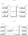
- FIGS. 5A and 5B are block diagrams of occupancy detection apparatuses according to embodiments of the present disclosure
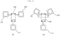
- FIG. 6 is a view referred to for describing antenna layouts in an occupancy detection apparatus according to an embodiment of the present disclosure.
- FIG. 7 is a flowchart illustrating a method for controlling an occupancy detection apparatus according to an embodiment of the present disclosure
- FIGS. 8 to 17 are views referred to for describing a method for controlling an occupancy detection apparatus according to an embodiment of the present disclosure.
- each of occupancy detection apparatuses 100a and 100b may include a transmitter 110 including the single transmission antenna 111 for outputting a transmission signal, a receiver 120 including the first and second reception antennas 121 and 122 for receiving reflected signals corresponding to the transmission signal, and a processor 130 for processing the reflected signals.
- the transmitter 110 may output a transmission signal to the outside (S710).
- the transmitter 110 may generate an IR-UWB impulse signal and output the IR-UWB impulse signal to the outside.
- the transmitter 110 may further include an impulse generator (not shown).
- the impulse generator may generate an IR-UWB impulse signal based on data for generation of a transmission signal, provided by the processor 130.
- the processor 130 may have the functionality of the impulse generator, and thus may generate a transmission signal and output the transmission signal to the outside through the transmission antenna 111.
- the processor 130 may be a kind of transceiver serving as a transmitter and a receiver.
- the processor 130 may have a bandwidth filter and thus may extract and process a signal in a predetermined frequency band.
- the transmission antenna 111 of the transmitter 110 is a directional antenna.
- the receiver 120 which includes the first and second reception antennas 121 and 122, may receive a signal which has been output from the transmitter 110 and reflected from an external object or a person (S720).
- the processor 130 may provide overall control to each of the occupancy detection apparatuses 100a and 100b, and process a signal for occupancy detection.
- the processor 130 may perform signal processing for the average value of signals repeatedly received a predetermined number of times through the first and second reception antennas 121 and 122.
- the processor 130 may control alternate switching between the first and second reception antennas 121 and 122 so that a plurality of reflected signals may be collected periodically through each of the first and second reception antennas 122.
- each of the occupancy detection apparatuses 100a and 100b may further include a switch 140 for alternately switching between the first and second reception antennas 121 and 122 so that a plurality of reflected signals may be collected periodically through each of the first and second reception antennas 122.
- the occupancy detection apparatus 100b may further include the dedicated controller 135 for controlling the switch 140.
- the first and second reception antennas 121 and 122 of the receiver 120 are directional antennas.
- a lens may be attached to each of the transmission antenna 111 and the first and second reception antennas 121 and 122 so that a transmission and reception angle may be narrowed and a transmission and reception distance may be increased.
- the first and second reception antennas 121 and 122 are preferably arranged to be symmetrical with respect to the processor 130 and the transmission antenna 111.
- the first reception antenna 121, the second reception antenna 122, and the transmission antenna 111 may be arranged in the form of 'T'.
- the first reception antenna 121, the second reception antenna 122, and the transmission antenna 111 may be arranged in the form of 'Y'.
- each of the occupancy detection apparatuses 100a and 100b may further include a memory 150 for storing data and an algorithm required for operations.
- each of the occupancy detection apparatuses 100a and 100b may further include a power supply 160 for receiving internal or external power and supplying required power to each component under the control of the processor 130.
- the power supply 160 may include one or more batteries and, in this case, the batteries may be chargeable built-in ones.
- a battery When needed, a battery may be detachably engaged with a body of each of the occupancy detection apparatuses 100a and 100b.
- the power supply 160 may include a connection port which may be configured as an exemplary interface electrically connected to an external charger for supplying power to charge the battery.
- the power supply 160 may be configured to charge the battery wirelessly without using the connection port.
- the power supply 160 may receive power by at least one of an inductive coupling scheme based on magnetic induction from an external wireless power transmitter, and a magnetic resonance coupling scheme based on electromagnetic resonance.
- each of the occupancy detection apparatuses 100a and 100b may further include an illumination unit 170 for outputting light in one or more colors.
- At least one light source is provided inside the illumination unit 170 and is preferably a Light Emitting Diode (LED).
- LED Light Emitting Diode
- the illumination unit 170 may output light, for power, communication, or an operation failure in each of the occupancy detection apparatuses 100a and 100b.
- the illumination unit 170 may output light in different colors according to power, communication, or operation states of each of the occupancy detection apparatuses 100a and 100b.
- each of the occupancy detection apparatuses 100a and 100b may further include a communication unit (not shown) for outputting light in one or more colors.
- the processor 130 may process a reflected signal corresponding to a transmission signal and thus acquires per-sample signal strengths.
- a sample may be configured to be about 4mm long(unit).
- a peak signal is selected through filtering, background subtraction, and cross-correlation.
- a basic signal process may be performed in the manner/order of a CLEAN algorithm.
- the processor 130 may perform dynamic background subtraction on the reflected signals received through the first and second reception antennas 121 and 122 (S730).
- the original signal of the reflected signals is subjected to background subtraction so that a background signal(noise) may be eliminated (S730).
- the received reflected signals contain a signal reflected from a stationary neighboring object as well as a signal reflected from a target.
- the signal reflected from the neighboring object should be processed and eliminated as a background. This process is called background subtraction.
- the processor 130 may eliminate a background signal corresponding to the background from the reflected signals by background subtraction (S730).
- the processor 130 may extract a correlation with the transmission signal from the signals free of the background signal, and extract signals reflected from an occupant in the reflected signals (S740).
- the correlation extraction is a process of searching for a signal matching to a transmission signal by cross-correlation.
- the processor 130 excludes a signal determined to be noise with no similarity to and correlation with the transmission signal from the reflected signals.
- the processor 130 extracts peak signals matching to an occupant signal characteristic (a threshold) from the extracted signals (S740), and select a target based on the peak signals (S750).
- a threshold an occupant signal characteristic
- the processor 130 may extract a peak signal from each of the signals received from the first and second reception antennas 121 and 122.
- the processor 130 may track the location of the target based on the histories of the signals received through the first and second reception antennas 121 and 122 (S760).
- FIG. 8 is a detailed flowchart illustrating the signal process of the processor 130.
- tracking of the location of an occupant may include selecting a received signal matching to a transmission signal and extracting a peak signal (S810), selecting a target corresponding to the extracted peak signal (S811, S812, S821, and S822), selecting/releasing the target as a tracking target (S831, S832, S840, S841, and S845), and tracking the location of the target (S850 and S860).
- signal processing may be performed on the average value of signals received N times (e.g., 30 times) from each of the left and right first and second reception antennas 121 and 122 of the occupancy detection apparatus 100.
- the transmission antenna 111 outputs a transmission signal (S710).
- the transmission signal is reflected from an occupant and received through the left first and right second reception antennas 121 and 122 (S720).
- the processor 130 processes the reflected signals received through the first and second reception antennas 121 and 122, to thereby acquire per-sample signal strengths.
- a sample may be configured to be a predetermined unit, for example, 4mm long.
- the occupancy detection apparatus 100 determines a tracking target based on the distance of a target signal processed in the first and second reception antennas 121 and 122, and tracks the tracking target.
- the occupancy detection apparatus 100 basically uses the distances DL between the first reception antenna 121 and tracking targets 911, 912, and 913 and the distances DR between the second reception antenna 122 and the tracking targets 911, 912, and 913 in sensing the positions P of the tracking targets 911, 912, and 913 and the distances D to the tracking targets 911, 912, and 913.
- the processor 130 extracts peak signals by subjecting the original signal to filtering, background subtraction, and cross-correlation (S810).
- a basic signal process may be performed in the manner/sequence of the known CLEAN algorithm.
- a background signal is eliminated from the original signal by background subtraction (S730).
- the received reflected signals contain a signal reflected from a stationary neighboring object as well as a signal reflected from a target.
- the signal reflected from the neighboring object should be processed and eliminated as a background. This process is called background subtraction.
- FIGS. 10A to 10F illustrate exemplary signals during the peak signal extraction S810.
- FIG. 10A is an exemplary view illustrating an original signal
- FIG. 10B is an exemplary view illustrating a signal obtained by normalizing the original signal to zero.
- the processor 130 may process a signal by normalizing the signal.
- the processor 130 may extract a repeated background signal from the normalized original signal by dynamic subtraction.
- the occupancy detection apparatus 100 may process signals by switching between the first and second reception antennas 121 and 122.
- FIGS. 10A, 10B, and 10C illustrate an exemplary process of processing a signal received from one of the first and second reception antennas 121 and 122
- FIG. 10D is an exemplary view illustrating a result of processing a signal received from the other reception antenna 121 or 122 in the same manner.
- a reflected signal i.e., impulse response
- the processor 130 may determine similarity and correlation over time between the transmission signal and the signals received through the first and second reception antennas 121 and 122.
- FIG. 10E is an exemplary view illustrating a result of normalizing a signal free of noise by cross-correlation, that is, a signal determined to be correlated with the transmission signal.
- the processor 130 may extract a peak signal by determining the strengths of the signals after the cross-correlation (S810).
- the final extracted signals may be amplified.
- the signals may be weak. Then, a threshold may be set, and signals having strengths equal to or greater than the threshold may be selected as final peak signals (S811 and S812).
- a signal received from a remote place is less than a signal reflected in a near place in terms of magnitude.
- an actual target may not be selected as a target.
- a processed signal is compensated according to a distance and a different threshold is set according to the distance. Only if the processed signal is compensated according to a distance and a different threshold is applied according to the distance, even a remote target may be sensed.
- a final peak signal may be selected in each of the signals received through the first and second reception antennas 121 and 122 (S811 and S812).
- the processor 130 may select a target based on the extracted and selected signals (S821 and S822).
- the extracted peak signal is subjected to steps S821 and S822 in which it is determined that the target is a person. Temporary signals such as noise and reflected signals may be eliminated from the peak signals extracted in the target selection steps S821 and S822 and the resulting signals may be managed in the memory 150.
- the target buffers are managed respectively in the first and second reception antennas, and the processor 130 may perform target selection, update, and abnormality processing by controlling the target buffers.
- a peak signal is generated a predetermined number of times (e.g., three times) successively in an adjacent area of the extracted peak signal, it may be determined that the target is a person, and the peak signal may be registered in a target buffer.
- the distance to the adjacent area spans 200 samples (75 to 80cm), and may be determined based on a person's stride (80cm for a 180-cm tall person).
- a distance measuring algorithm may be performed at an average rate of 320ms, which means that the algorithm may be performed three times within 1 second.
- a signal sensed successively within 1 second within a person's stride may be buffered in the target buffer.
- FIG. 10G illustrates an example in which, when second and third signals are sensed within N samples of a first signal, it is determined that a corresponding object is an actually moving object (person) and the corresponding signal is registered in the target buffer.
- a corresponding distance is updated for the signal registered once to the target buffer, according to a movement (S831 and S832).
- An extracted peak signal generated within N samples (e.g., 200 samples) is continuously updated based on a final distance.
- the update may also be performed for each of the first and second reception antennas 121 and 122, like other steps.
- the generated signal has not been generated within 200 samples of the signal managed in the target buffer, the signal is subjected as a new signal to the target selection step.
- T1' is generated with respect to T1
- a corresponding target is updated to T1'.
- T1" is also handled in the same manner.
- T2 is regarded as a new target and thus a target update is not performed. In this case, a target selection operation is performed separately for T2.
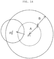
- the processor 130 may control a search range to be extended by a predetermined area, for example, 10 samples in the next period. This is done to extend an update range in case a movement is too fast to be sensed.
- variable search range may be referred to as a moving range factor.
- the processor 130 may not sense a movement (for about 35cm for about 3 seconds, in the case of 9 times) even after the update range is increased repeatedly a predetermined number of times (e.g., 9 times), the processor 130 may reset the search range to zero.
- the processor 130 maintains target information in the target buffer for a predetermined time and then excludes the corresponding target.
- the reason for maintaining the target information for the predetermined time is to manage the target during tracking in consideration of a case in which the target is stationary.
- the processor 130 may reset the moving range factor to zero and then perform the target update operation.
- FIG. 12 illustrates an example in which if a signal is not sensed after the target T1 is updated to T1', a signal sensing range is increased by up to A samples.
- the occupancy detection apparatus 100 selects, tracks, and releases a tracking target based on a distance of a target signal processed in the first and second reception antennas 121 and 122.
- the occupancy detection apparatus 100 first senses and determines the location and distance of a tracking target (S840) and registers the tracking target according to a condition (S845).
- an exceptional situation such as a case in which an object stops or two or more persons are overlapped during tracking (S850)
- the occupancy detection apparatus 100 performs tracking (S850), while processing the exceptional situation (S860). and releases tracking according to a release condition (S845).
- the occupancy detection apparatus 100 may basically use the difference between the distance between a tracking target and the first reception antenna RX1 and the distance between the tracking target and the second reception antenna RX2 in sensing the position P and distance D of the tracking target.
- the difference Ddiff between distances is calculated and compared with a predetermined reference Dcenter, thereby determining the location of the target.
- the processor 130 may set a specific area adjacent to a sensing range as a waiting space, and track the location of a target that has moved from the waiting space into the sensing range.
- the processor 130 may determine whether the target has entered the waiting space (S841), select a target that has entered the waiting space as a tracking target (S845), and continuously track the tracking target by updating the location and distance of the tracking target (S850).
- a first area 1310 in which only a left target is sensed, a second area 1320 in which only a right target is sensed, and a third area 1330 in which only a remote target is sensed may be set as waiting spaces.
- the waiting spaces 1310, 1320, and 1330 may be set to be adjacent to a sensing range 1340.
- only a left reception antenna for example, only the first reception antenna may be configured to receive a signal from the first area 1310, and only a right reception antenna, for example, only the second reception antenna may be configured to receive a signal from the second area 1320.
- the first and second reception antennas 121 and 122 may alternately receive signals from the third area 1330 and the sensing range 1340 by switching.
- the waiting spaces 1310, 1320, and 1330 are waiting areas which may be regarded as preparation areas from which a target is about to enter the sensing range 1340 in which the target is tracked.
- the occupancy detection apparatus 100 may register a tracking target based on a sensed location and distance.
- a target registered in a tracking buffer may be tracked while being updated based on a distance updated according to reflected signals received through the first and second reception antennas 121 and 122.
- the processor 130 may register the object in the memory 150 or the tracking buffer and track the object.
- the processor 130 may release the tracking target from the tracking buffer and regard the released target as a waiting person.
- the tracking buffer may be provided together with the target buffer in the memory 150.
- an exceptional situation for example, an object stops during tracking, a signal may not be received even though a move-out condition is not satisfied.
- the exceptional situation may be handled so that the tracking state may be maintained for the target for which the move-out condition is not satisfied (S860).
- the processor 130 may determine that the persons are separated.
- the targets are separated, they are registered as new tracking targets without the target selection and tracking registration process.
- the persons enter together and are not separated they may be determined to be a single tracking target.
- P2 may be registered as a new tracking target.
- the processor 130 may determine that the persons have been separated.
- FIGS. 15 , 16 , and 17 illustrate results of a test in which the occupancy detection apparatus is operated in a space of about 15mx17m.
- FIG. 15 (a) and (b) illustrate distributions of repeated errors per distance for the left first and right second reception antennas.
- (b) of FIG. 15 a specific area 1515 corresponding to a specific area 1510 in (a) of FIG. 15 .
- the first reception antenna has a distance error ranging from -0.32m to +0.97m
- the second reception antenna has a distance error ranging from -0.39m to +0.76m.
- the error averages of the first and second reception antennas tend to be equal for the same distance. For example, for 5m, the first reception antenna has an error of 0.15m and the second reception antenna has a similar error of 0.16m.
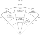
- FIG. 16 illustrates average values of RX1 and RX2 in each zone and results for left, right, and center zones.
- FIG. 16 describes a test in which an area within 5m is divided into zones on a 1m basis according to left, right, and center, and the accuracy of determining the zones.
- measurement is performed while persons under test are moving slightly in each zone, and 100 measurement values are taken. Overall errors are observed at the boundaries between the left, right, and the center zones, whereas an accuracy of 100% is achieved in zones not near to the boundaries.
- FIG. 17 illustrates tracking accuracies as results of measured distances and determined locations regarding directions in which a person moves and places in which the person stays.
- FIG. 17 when a motion is tracked within 2 to 14m, the presence or absence of an occupant is checked when the occupant enters each zone.
- a person under test To check entry and exit, a person under test enters a tracking zone from a location apart to the right by 2 to 3m and moves out of the tracking zone to the left by 14m, and maintains a normal stride and speed during entry and exit. The person under test stays 3 seconds in each zone and then moves to the next zone, and a tracking result is measured in real time.
- the person under test moves at a normal stride, and stays 2 seconds in each zone.
- An accuracy of 93.1% is achieved across the total zones, and the tracking target is not lost at all.
- the average values of roaming times are checked.
- the location of an occupant can be accurately measured and tracked by means of a single occupancy detection apparatus. Further, a plurality of zones can be sensed by the single device through location tracking.
- the occupancy detection apparatus is easily installed, and reduces fabrication cost and management cost.
- a location-based control system for reducing the energy consumption of a building may be realized using the occupancy detection apparatus.
- the occupancy detection apparatus apparatus and the method for controlling the same are not restricted to the exemplary embodiments set forth herein. Therefore, variations and combinations of the exemplary embodiments set forth herein may fall within the scope of the present disclosure.
- the method for controlling the occupancy detection apparatus may be implemented as code that can be written on a computer-readable recording medium and thus read by a processor.
- the computer-readable recording medium may be any type of recording device in which data is stored in a computer-readable manner. Examples of the computer-readable recording medium include a ROM, a RAM, a CD-ROM, a magnetic tape, a floppy disc, an optical data storage, and a carrier wave (e.g., data transmission over the Internet).
- the computer-readable recording medium can be distributed over a plurality of computer systems connected to a network so that computer-readable code is written thereto and executed therefrom in a decentralized manner. Programs, code, and code segments to realize the embodiments herein can be construed by one of ordinary skill in the art.
Landscapes
- Engineering & Computer Science (AREA)
- Radar, Positioning & Navigation (AREA)
- Remote Sensing (AREA)
- Computer Networks & Wireless Communication (AREA)
- Physics & Mathematics (AREA)
- General Physics & Mathematics (AREA)
- Chemical & Material Sciences (AREA)
- Combustion & Propulsion (AREA)
- Mechanical Engineering (AREA)
- General Engineering & Computer Science (AREA)
- Business, Economics & Management (AREA)
- Emergency Management (AREA)
- Power Engineering (AREA)
- Radar Systems Or Details Thereof (AREA)
- Geophysics And Detection Of Objects (AREA)
Abstract
Description
- The present disclosure relates to an occupancy detection apparatus and a method for controlling the same, and more particularly, to an occupancy detection apparatus based on Impulse Response-Ultra Wide Band (IR-UWB), and a method for controlling the same
- Offices, schools, clinics, a common living space in a house, and buildings provide necessary services to users. For example, a Heating, Ventilation, Air Conditioning (HVAC) system is a representative facility system that offers a service.
- Such a service is provided using an energy source like electricity or gas. Korea Energy Agency publicized the results of an analysis of energy consumption characteristics of each domestic sector in 2014, which reveal that a building sector occupies about 24.2% of the total domestic energy consumption, and the energy increase rate of the building sector is higher than an industrial sector and a transportation sector.
- It is expected that the energy consumption of the building sector will further be increased due to the trend toward large buildings and enhanced convenience. Accordingly, reduction of energy in buildings may lead to a great decrease in total energy consumption.
- In order to reduce the energy consumption of a building without making users feel uncomfortable, more and more research has recently been conducted on intelligent control techniques for providing as much an illumination service and a heating and cooling service as needed only at a necessary time instant.
- For intelligent control, energy consumption is estimated based on an energy consumption model and a service is controlled according to the estimated energy consumption, or a service is controlled based on a user's location.
- According to the energy consumption model-based estimation control scheme, a building under control and facilities (a chiller, a cooling tower, a pump, and so on) in the building are modeled, and an energy consumption is estimated. An optimum facility operation scheme is provided based on the estimated energy consumption, thereby saving energy.
- For this purpose, a technology of modeling a building and facilities in the building, and accurate indoor/outdoor state information about the building determined by means of various sensors (for sensing a flow rate, temperature/humidity, and so on) are required. To build this system in the building, the initial investment is huge.
- According to the location-based control scheme, a service is provided based on the location of a user in a building. The illumination and cooling/heating of an empty space are turned off, and a service is provided adaptively to a place in which a user is located, thereby saving energy.
- Because a number of services may be provided by indoor location sensing, multi-sided research has been made to sense a motion of a person and locate the person in an indoor environment.
- Conventionally, occupancy is detected by a sensor or Radio Frequency (RF). However, the conventional method has limitations in providing a service by detecting the accurate location and distance of an object in a large space due to its constraint in terms of installation of a plurality of sensors and accuracy.
-
FIG. 1 is a simplified conceptual view illustrating a conventional occupancy detection apparatus using a Passive InfraRed (PIR) sensor. - The PIR sensor, also called a moving IR detector, senses an object that radiates IR light. Every object having a temperature above the absolute temperature zero radiates IR light, and the temperature (36.5°C) of a human body is representable within an IR range.
- The occupancy detection apparatus using a PIR sensor includes an
IR radiator 10 and alight receiving sensor 30. IR light emitted from theIR radiator 10 is reflected from aperson 20. Thelight receiving sensor 30 may sense reflectedlight 31, and accordingly determine whether there is any occupant. - Owing to its cheap price and sensitiveness to a motion, the PIR sensor is mostly used indoors. However, the high sensitivity of the PIR sensor to sun light, a flash, or temperature may lead to malfunction of the PIR sensor.
- Moreover, since the PIR sensor is capable of determining only the presence or absence of a moving object in a space, it is difficult to provide a per-location service in a large space with the PIR sensor.
- In other words, since the PIR sensor determines only the presence or absence of any person in a sensing space and does not determine the location of a person, the PIR sensor may not be used in a large conference room.
- Although a technique of conducting communication between PIR sensors has also been studied to locate a person in a large space, such a technique requires use of a plurality of PIR sensors.
-
FIG. 2 is a simplified conceptual view illustrating a conventional Impulse Response-Ultra Wide Band (IR-UWB)-based occupancy detection apparatus, andFIG. 3 is a graph illustrating the spectrums of a UWB scheme and other schemes, referred to for describing UWB. - Referring to
FIG. 2 , the conventional IR-UWB-based occupancy detection apparatus includes at least threeradar modules controller 42. - Each of the
radar modules - Referring to the frequency spectrums illustrated in
FIG. 3 , aUWB system 61 is designed by a wireless transmission technology in which digital data is transmitted in an ultra wide frequency band with very low power. The UWBsystem 61 has a relatively low spectrum across a very wide frequency band, compared to a conventionalnarrow band system 63 or a conventional wideband Code Division Multiple Access (CDMA)system 65. - The UWB-based location sensing or occupancy detection scheme consumes low power and is robust against a jamming and multi-path environment. Due to its high accuracy of location detection, the UWB-based location sensing or occupancy detection scheme is widely used in determining an accurate distance.
- UWB-based schemes are classified into a carrier-based scheme and an impulse-based (carrier-free) scheme. In general, a scheme of calculating a distance using the Time of Arrival (ToA) of IR reflected waves is often used. This takes the advantage of high distance measurement accuracy that UWB offers due to non-use of a carrier and use of very short pulses (nsec).
- However, despite the high distance measurement accuracy, the conventional IR-UWB-based scheme suffers from an installation limitation in that a location can be determined only through a plurality of pieces of equipment.
- Referring to
FIG. 2 , conventionally, the three ormore radar modules occupant 50 is collected through theradar modules occupant 50. - Since each of the
radar modules - To locate the
occupant 50 accurately, the distances measured by theradar modules - Therefore, the
controller 42 should be additionally provided to collect sensing data from the plurality ofradar modules controller 42 and theradar modules - That is, the conventional occupancy detection scheme requires the three or
more radar modules person 50, and additionally, thecontroller 42 for performing a positioning algorithm. - As a result, the number of modules and cost for occupancy detection are increased.
- Further, the
conventional radar modules occupant 50 in a large space spanning 10m or larger, a double or more of the sensors are required. - To determine a distance and a location through a single device by dividing a large space into smaller zones without imposing constraints on users, hardware and an algorithm other than used in the conventional approaches need to be designed.
- In this context, active research is conducted on a technique of locating a user indoors through a single device to perform location-based control and thus save energy in a building.
- Therefore, the present disclosure has been made in view of the above problems, and an aspect of the present disclosure is to provide an occupancy detection apparatus for accurately measuring the location of an occupant by means of a single device, and a method for controlling the same.
- Another aspect of the present disclosure is to an occupancy detection apparatus for efficiently measuring and tracking a location of an occupant, while saving fabrication cost and management cost, and a method for controlling the same.
- Another aspect of the present disclosure is to an occupancy detection apparatus for supporting location-based control to reduce the energy consumption of a building, and a method for controlling the same.
- In an aspect of the present disclosure, an occupancy detection apparatus includes a transmitter including one transmission antenna for outputting a transmission signal, a receiver including a first reception antenna and a second reception antenna, each for receiving a reflected signal corresponding to the transmission signal, and a processor for eliminating a background signal corresponding to a background from each of the reflected signals, and extracting a signal reflected from an occupant from each of the reflected signals by extracting a correlation between the transmission signal and the reflected signal free of the background signal.
- In another aspect of the present disclosure, a method for controlling an occupancy detection apparatus includes outputting a transmission signal through one transmission antenna, receiving a reflected signal corresponding to the transmission signal through each of a first reception antenna and a second reception antenna, eliminating a background signal corresponding to a background from each of the reflected signals, and extracting a signal reflected from an occupant from each of the reflected signals by extracting a correlation between the transmission signal and the reflected signal free of the background signal.
- The above and other objects, features and other advantages of the present disclosure will be more clearly understood from the following detailed description taken in conjunction with the accompanying drawings, in which:
-
FIG. 1 is a simplified conceptual view of a conventional occupancy detection apparatus using a Passive InfraRed (PIR) sensor; -
FIG. 2 is a simplified conceptual view of a conventional Impulse Response-Ultra Wide Band (IR-UWB)-based occupancy detection apparatus; -
FIG. 3 is a view referred to for describing UWB; -
FIG. 4 is a simplified conceptual view of an occupancy detection apparatus according to an embodiment of the present disclosure; -
FIGS. 5A and 5B are block diagrams of occupancy detection apparatuses according to embodiments of the present disclosure; -
FIG. 6 is a view referred to for describing antenna layouts in an occupancy detection apparatus according to an embodiment of the present disclosure; -
FIG. 7 is a flowchart illustrating a method for controlling an occupancy detection apparatus according to an embodiment of the present disclosure; and -
FIGS. 8 to 17 are views referred to for describing a method for controlling an occupancy detection apparatus according to an embodiment of the present disclosure. - Embodiments of the present disclosure will be described below in detail with reference to the attached drawings. However, the embodiments do not limit the present disclosure, and various modifications may be made to the present disclosure.
- To describe the present disclosure clearly and simply, a part with no relation to the present disclosure is not illustrated in the drawings, and like reference numerals denote the same or very similar components throughout the specification.
- The terms 'module' and 'unit' used to signify components are used herein to help the understanding of the components and thus they should not be considered as having specific meanings or roles. Accordingly, the terms 'module' and 'unit' may be used interchangeably.
-
FIG. 4 is a simplified conceptual view illustrating an occupancy detection apparatus according to an embodiment of the present disclosure. - Referring to
FIG. 4 , as the location of anoccupant 70 is detected by a singleoccupancy detection apparatus 100 in an occupancy detection method according to an embodiment of the present disclosure, the number of occupancy sensors may be reduced and thus the configuration of occupancy sensors may be simplified. - According to an embodiment of the present disclosure, the
occupancy detection apparatus 100 may be configured to include onetransmission antenna 111 and tworeception antennas - The
occupancy detection apparatus 100 senses and tracks the location of an occupant by processing two signals received from the tworeception antennas - A
switch 140 may switch between the first andsecond reception antennas reception antennas switch 140 may operate under the control of acontroller 135. - A received signal may be an impulse response resulting from reflection of an impulse signal output from the
transmission antenna 111 from an external object or person. - The
occupancy detection apparatus 100 may also calculate a per-distance signal level based on the average value of a predetermined number of received signals during processing of the received signals, and use the calculated per-distance signal level as data for occupancy detection. - The
occupancy detection apparatus 100 may eliminate a signal generated from a background from each of the received signals and perform dynamic background subtraction on a motion. - Subsequently, the
occupancy detection apparatus 100 may extract a correlation with the transmission signal from a background differential signal, and thus extract only a signal reflected from theoccupant 70 from the received signal. - The
occupancy detection apparatus 100 may determine whether a detected object is actually a person by selecting only a peak signal matching to an occupant signal characteristic from among extracted signals. - Further, the
occupancy detection apparatus 100 may select a target according to a direction from which the target enters a sensing range, and track the location of the target based on the histories of signals received from the left and right first andsecond reception antennas - According to the present disclosure, illumination/Heating, Ventilation, Air Conditioning (HVAC) may be controlled intelligently and a service may be provided to users as much as needed, through occupancy detection.
- According to the present disclosure, the occupancy detection apparatus is easily installed, reduces cost, and is capable of long-distance occupancy detection by pre-processing a received signal, compared to a conventional occupancy detection apparatus.
- According to an embodiment of the present disclosure, the occupancy detection apparatus may sense a plurality of zones through a single piece of equipment by location tracking.
- With reference to the attached drawings, an occupancy detection apparatus and a method for controlling the same according to an embodiment of the present disclosure will be described below in detail.
-
FIGS. 5A and 5B are block diagrams of occupancy detection apparatuses according to embodiments of the present disclosure, andFIG. 6 is a view referred to for describing antenna layouts in an occupancy detection apparatus according to an embodiment of the present disclosure. -
FIG. 7 is a flowchart illustrating a method for controlling an occupancy detection apparatus according to an embodiment of the present disclosure, andFIGS. 8 to 17 are views referred to for describing a method for controlling an occupancy detection apparatus according to an embodiment of the present disclosure. - Referring to the drawings, each of
occupancy detection apparatuses transmitter 110 including thesingle transmission antenna 111 for outputting a transmission signal, areceiver 120 including the first andsecond reception antennas processor 130 for processing the reflected signals. - The
transmitter 110 may output a transmission signal to the outside (S710). For example, thetransmitter 110 may generate an IR-UWB impulse signal and output the IR-UWB impulse signal to the outside. - For this purpose, the
transmitter 110 may further include an impulse generator (not shown). In this case, the impulse generator may generate an IR-UWB impulse signal based on data for generation of a transmission signal, provided by theprocessor 130. - Alternatively or additionally, the
processor 130 may have the functionality of the impulse generator, and thus may generate a transmission signal and output the transmission signal to the outside through thetransmission antenna 111. - The
processor 130 may be a kind of transceiver serving as a transmitter and a receiver. - The
processor 130 may have a bandwidth filter and thus may extract and process a signal in a predetermined frequency band. - Preferably, the
transmission antenna 111 of thetransmitter 110 is a directional antenna. - Meanwhile, the
receiver 120, which includes the first andsecond reception antennas transmitter 110 and reflected from an external object or a person (S720). - The
processor 130 may provide overall control to each of theoccupancy detection apparatuses - The
processor 130 may perform signal processing for the average value of signals repeatedly received a predetermined number of times through the first andsecond reception antennas - According to an embodiment, the
processor 130 may control alternate switching between the first andsecond reception antennas second reception antennas 122. - Alternatively or additionally, each of the
occupancy detection apparatuses switch 140 for alternately switching between the first andsecond reception antennas second reception antennas 122. - In this case, the
occupancy detection apparatus 100b according to an embodiment of the present disclosure may further include thededicated controller 135 for controlling theswitch 140. - Preferably, the first and
second reception antennas receiver 120 are directional antennas. - According to an embodiment of the present disclosure, a lens may be attached to each of the
transmission antenna 111 and the first andsecond reception antennas - Referring to (a) and (b) of
FIG. 6 , the first andsecond reception antennas processor 130 and thetransmission antenna 111. - As illustrated in (a) of
FIG. 6 , thefirst reception antenna 121, thesecond reception antenna 122, and thetransmission antenna 111 may be arranged in the form of 'T'. - As illustrated in (b) of
FIG. 6 , thefirst reception antenna 121, thesecond reception antenna 122, and thetransmission antenna 111 may be arranged in the form of 'Y'. - According to an embodiment of the present disclosure, each of the
occupancy detection apparatuses memory 150 for storing data and an algorithm required for operations. - Further, the
memory 150 may store and manage reflected signals received through thereceiver 120.
According to an embodiment of the present disclosure, each of theoccupancy detection apparatuses power supply 160 for receiving internal or external power and supplying required power to each component under the control of theprocessor 130. - The
power supply 160 may include one or more batteries and, in this case, the batteries may be chargeable built-in ones. - When needed, a battery may be detachably engaged with a body of each of the
occupancy detection apparatuses
Thepower supply 160 may include a connection port which may be configured as an exemplary interface electrically connected to an external charger for supplying power to charge the battery. - Further, the
power supply 160 may be configured to charge the battery wirelessly without using the connection port. In this case, thepower supply 160 may receive power by at least one of an inductive coupling scheme based on magnetic induction from an external wireless power transmitter, and a magnetic resonance coupling scheme based on electromagnetic resonance. - According to an embodiment of the present disclosure, each of the
occupancy detection apparatuses illumination unit 170 for outputting light in one or more colors. - At least one light source is provided inside the
illumination unit 170 and is preferably a Light Emitting Diode (LED). - The
illumination unit 170 may output light, for power, communication, or an operation failure in each of theoccupancy detection apparatuses - The
illumination unit 170 may output light in different colors according to power, communication, or operation states of each of theoccupancy detection apparatuses - According to an embodiment of the present disclosure, each of the
occupancy detection apparatuses - The
processor 130 may process a reflected signal corresponding to a transmission signal and thus acquires per-sample signal strengths. Herein, a sample may be configured to be about 4mm long(unit). - For this processed signal (original signal), a peak signal is selected through filtering, background subtraction, and cross-correlation. A basic signal process may be performed in the manner/order of a CLEAN algorithm.
- The
processor 130 may perform dynamic background subtraction on the reflected signals received through the first andsecond reception antennas 121 and 122 (S730). - The original signal of the reflected signals is subjected to background subtraction so that a background signal(noise) may be eliminated (S730). The received reflected signals contain a signal reflected from a stationary neighboring object as well as a signal reflected from a target. Thus, the signal reflected from the neighboring object should be processed and eliminated as a background. This process is called background subtraction.
- The
processor 130 may eliminate a background signal corresponding to the background from the reflected signals by background subtraction (S730). - The
processor 130 may extract a correlation with the transmission signal from the signals free of the background signal, and extract signals reflected from an occupant in the reflected signals (S740). - The correlation extraction is a process of searching for a signal matching to a transmission signal by cross-correlation. The
processor 130 excludes a signal determined to be noise with no similarity to and correlation with the transmission signal from the reflected signals. - Subsequently, the
processor 130 extracts peak signals matching to an occupant signal characteristic (a threshold) from the extracted signals (S740), and select a target based on the peak signals (S750). - In the peak signal extraction step S740, the
processor 130 may extract a peak signal from each of the signals received from the first andsecond reception antennas - The
processor 130 may track the location of the target based on the histories of the signals received through the first andsecond reception antennas 121 and 122 (S760). -
FIG. 8 is a detailed flowchart illustrating the signal process of theprocessor 130. - Referring to
FIG. 8 , tracking of the location of an occupant may include selecting a received signal matching to a transmission signal and extracting a peak signal (S810), selecting a target corresponding to the extracted peak signal (S811, S812, S821, and S822), selecting/releasing the target as a tracking target (S831, S832, S840, S841, and S845), and tracking the location of the target (S850 and S860). In each step, signal processing may be performed on the average value of signals received N times (e.g., 30 times) from each of the left and right first andsecond reception antennas occupancy detection apparatus 100. - The
transmission antenna 111 outputs a transmission signal (S710). The transmission signal is reflected from an occupant and received through the left first and rightsecond reception antennas 121 and 122 (S720). Theprocessor 130 processes the reflected signals received through the first andsecond reception antennas - Referring to
FIG. 9 , according to an embodiment of the present disclosure, theoccupancy detection apparatus 100 determines a tracking target based on the distance of a target signal processed in the first andsecond reception antennas - According to an embodiment of the present disclosure, the
occupancy detection apparatus 100 basically uses the distances DL between thefirst reception antenna 121 and trackingtargets second reception antenna 122 and the tracking targets 911, 912, and 913 in sensing the positions P of the tracking targets 911, 912, and 913 and the distances D to the tracking targets 911, 912, and 913. - The
processor 130 extracts peak signals by subjecting the original signal to filtering, background subtraction, and cross-correlation (S810). A basic signal process may be performed in the manner/sequence of the known CLEAN algorithm. - A background signal is eliminated from the original signal by background subtraction (S730). The received reflected signals contain a signal reflected from a stationary neighboring object as well as a signal reflected from a target. The signal reflected from the neighboring object should be processed and eliminated as a background. This process is called background subtraction.
-
FIGS. 10A to 10F illustrate exemplary signals during the peak signal extraction S810. -
FIG. 10A is an exemplary view illustrating an original signal, andFIG. 10B is an exemplary view illustrating a signal obtained by normalizing the original signal to zero. Theprocessor 130 may process a signal by normalizing the signal. - As illustrated in
FIG. 10C , theprocessor 130 may extract a repeated background signal from the normalized original signal by dynamic subtraction. - Meanwhile, the
occupancy detection apparatus 100 according to an embodiment of the present disclosure may process signals by switching between the first andsecond reception antennas -
FIGS. 10A, 10B, and 10C illustrate an exemplary process of processing a signal received from one of the first andsecond reception antennas FIG. 10D is an exemplary view illustrating a result of processing a signal received from theother reception antenna - After the background subtraction, a reflected signal (i.e., impulse response) matching to the transmission signal is detected. The
processor 130 may determine similarity and correlation over time between the transmission signal and the signals received through the first andsecond reception antennas - By this operation, a signal determined to be noise with no similarity to and no correlation with the transmission signal is excluded from the received signals.
-
FIG. 10E is an exemplary view illustrating a result of normalizing a signal free of noise by cross-correlation, that is, a signal determined to be correlated with the transmission signal. - Referring to
FIG. 10F , theprocessor 130 may extract a peak signal by determining the strengths of the signals after the cross-correlation (S810). In addition, the final extracted signals may be amplified. - In the case of multi-path received signals, the signals may be weak. Then, a threshold may be set, and signals having strengths equal to or greater than the threshold may be selected as final peak signals (S811 and S812).
- However, if the same threshold is applied to all distances, a signal received from a remote place is less than a signal reflected in a near place in terms of magnitude. As a consequence, an actual target may not be selected as a target.
- Therefore, it is more preferred that a processed signal is compensated according to a distance and a different threshold is set according to the distance. Only if the processed signal is compensated according to a distance and a different threshold is applied according to the distance, even a remote target may be sensed.
- Meanwhile, like the peak signal extraction, a final peak signal may be selected in each of the signals received through the first and
second reception antennas 121 and 122 (S811 and S812). - The
processor 130 may select a target based on the extracted and selected signals (S821 and S822). - The extracted peak signal is subjected to steps S821 and S822 in which it is determined that the target is a person. Temporary signals such as noise and reflected signals may be eliminated from the peak signals extracted in the target selection steps S821 and S822 and the resulting signals may be managed in the
memory 150. - It is efficient in terms of speed to manage the extracted peak signals in additional target buffers.
- According to an embodiment of the present disclosure, the target buffers are managed respectively in the first and second reception antennas, and the
processor 130 may perform target selection, update, and abnormality processing by controlling the target buffers. - In the target selection steps S821 and S822, if a peak signal is generated a predetermined number of times (e.g., three times) successively in an adjacent area of the extracted peak signal, it may be determined that the target is a person, and the peak signal may be registered in a target buffer.
- For example, the distance to the adjacent area spans 200 samples (75 to 80cm), and may be determined based on a person's stride (80cm for a 180-cm tall person).
- Further, a distance measuring algorithm may be performed at an average rate of 320ms, which means that the algorithm may be performed three times within 1 second.
- Eventually, a signal sensed successively within 1 second within a person's stride may be buffered in the target buffer.
-
FIG. 10G illustrates an example in which, when second and third signals are sensed within N samples of a first signal, it is determined that a corresponding object is an actually moving object (person) and the corresponding signal is registered in the target buffer. - A corresponding distance is updated for the signal registered once to the target buffer, according to a movement (S831 and S832). An extracted peak signal generated within N samples (e.g., 200 samples) is continuously updated based on a final distance.
- The update may also be performed for each of the first and
second reception antennas - If the generated signal has not been generated within 200 samples of the signal managed in the target buffer, the signal is subjected as a new signal to the target selection step.
- Referring to
FIGS. 11A and 11B , if T1' is generated with respect to T1, a corresponding target is updated to T1'. In the examples ofFIG. 11C , T1" is also handled in the same manner. - On the other hand, as illustrated in
FIG. 11D , in the start where the target T becomes T1', if a signal T2 is generated outside a signal sensing range, T2 is regarded as a new target and thus a target update is not performed. In this case, a target selection operation is performed separately for T2. - Meanwhile, in the target update steps S831 and S822, an abnormal situation may occur during the target update.
- For example, if a signal is not sensed during target update, the
processor 130 may control a search range to be extended by a predetermined area, for example, 10 samples in the next period. This is done to extend an update range in case a movement is too fast to be sensed. - Meanwhile, a variable search range may be referred to as a moving range factor.
- Meanwhile, if the
processor 130 may not sense a movement (for about 35cm for about 3 seconds, in the case of 9 times) even after the update range is increased repeatedly a predetermined number of times (e.g., 9 times), theprocessor 130 may reset the search range to zero. - Further, after the reset, the
processor 130 maintains target information in the target buffer for a predetermined time and then excludes the corresponding target. The reason for maintaining the target information for the predetermined time is to manage the target during tracking in consideration of a case in which the target is stationary. - On the other hand, if a signal is sensed again within the search range during increasing the search range, the
processor 130 may reset the moving range factor to zero and then perform the target update operation. -
FIG. 12 illustrates an example in which if a signal is not sensed after the target T1 is updated to T1', a signal sensing range is increased by up to A samples. - (a) of
FIG. 12 illustrates a signal sensing range separately as a default search range N and an extended search range A, and (b) ofFIG. 12 intuitively illustrates extension of an actual search range. - According to an embodiment of the present disclosure, the
occupancy detection apparatus 100 selects, tracks, and releases a tracking target based on a distance of a target signal processed in the first andsecond reception antennas - According to an embodiment of the present disclosure, the
occupancy detection apparatus 100 first senses and determines the location and distance of a tracking target (S840) and registers the tracking target according to a condition (S845). - According to an embodiment of the present disclosure, if an exceptional situation occurs such as a case in which an object stops or two or more persons are overlapped during tracking (S850), the
occupancy detection apparatus 100 performs tracking (S850), while processing the exceptional situation (S860). and releases tracking according to a release condition (S845). - According to an embodiment of the present disclosure, the
occupancy detection apparatus 100 may basically use the difference between the distance between a tracking target and the first reception antenna RX1 and the distance between the tracking target and the second reception antenna RX2 in sensing the position P and distance D of the tracking target. - Referring to
FIG. 9 again, for signals determined as targets in RX1(DL) and RX2(DR), the difference Ddiff between distances is calculated and compared with a predetermined reference Dcenter, thereby determining the location of the target. - For example, if the difference Ddiff is equal to or less than the predetermined reference Dcenter, it is determined that the target is located at the center (PC), and if the difference Ddiff is greater than the predetermined reference Dcenter, it is determined that the target is located to the left (PL)/right (PR). A basic method for determining a distance and a location is given as follows.


- According to an embodiment, the
processor 130 may set a specific area adjacent to a sensing range as a waiting space, and track the location of a target that has moved from the waiting space into the sensing range. - That is, the
processor 130 may determine whether the target has entered the waiting space (S841), select a target that has entered the waiting space as a tracking target (S845), and continuously track the tracking target by updating the location and distance of the tracking target (S850). - Referring to
FIG. 13 , afirst area 1310 in which only a left target is sensed, asecond area 1320 in which only a right target is sensed, and athird area 1330 in which only a remote target is sensed may be set as waiting spaces. - The waiting
spaces sensing range 1340. - According to an embodiment, only a left reception antenna, for example, only the first reception antenna may be configured to receive a signal from the
first area 1310, and only a right reception antenna, for example, only the second reception antenna may be configured to receive a signal from thesecond area 1320. - In this case, the first and
second reception antennas third area 1330 and thesensing range 1340 by switching. - The waiting
spaces sensing range 1340 in which the target is tracked. - According to an embodiment of the present disclosure, the
occupancy detection apparatus 100 may register a tracking target based on a sensed location and distance. A target registered in a tracking buffer may be tracked while being updated based on a distance updated according to reflected signals received through the first andsecond reception antennas - When an object sensed in the waiting
space sensing range 1340, theprocessor 130 may register the object in thememory 150 or the tracking buffer and track the object. - If the tracking target moves out of the
sensing range 1340 to the waitingspace processor 130 may release the tracking target from the tracking buffer and regard the released target as a waiting person. - Meanwhile, the tracking buffer may be provided together with the target buffer in the
memory 150. - Preferably, it is efficient in terms of speed to separately include the tracking buffer from the
memory 150 and manage tracking information in the tracking buffer. - Meanwhile, when an exceptional situation occurs, for example, an object stops during tracking, a signal may not be received even though a move-out condition is not satisfied. The exceptional situation may be handled so that the tracking state may be maintained for the target for which the move-out condition is not satisfied (S860).
- This is done to maintain the target buffer for a predetermined time during target selection and update.
- Meanwhile, an exceptional situation may occur, in which two or more persons enter from the same location.
- For example, when two persons enter the
sensing range 1340 from the leftthird area 1330, a case in which they are separated after entry may be considered. Thus, if a signal is sensed in a specific range from the position and distance of a place from which they enter, for example, in an area apart by 200 to 400 samples, theprocessor 130 may determine that the persons are separated. - If it is determined that the targets are separated, they are registered as new tracking targets without the target selection and tracking registration process.
- If the persons enter together and are not separated, they may be determined to be a single tracking target.
- Referring to
FIG. 14 , if two persons are at the same position P1 and then sensed at P2, P2 may be registered as a new tracking target. Herein, if a signal is sensed at a location apart from the entered position and distance of the persons by A to B samples, theprocessor 130 may determine that the persons have been separated. -
FIGS. 15 ,16 , and17 illustrate results of a test in which the occupancy detection apparatus is operated in a space of about 15mx17m. - In
FIG. 15 , (a) and (b) illustrate distributions of repeated errors per distance for the left first and right second reception antennas. In (b) ofFIG. 15 , aspecific area 1515 corresponding to aspecific area 1510 in (a) ofFIG. 15 . - Referring to
FIG. 15 , it is noted that a distribution of errors within 20cm occupies 90% or above of total errors. The first reception antenna has a distance error ranging from -0.32m to +0.97m, and the second reception antenna has a distance error ranging from -0.39m to +0.76m. These are error ranges which are possible due to motions of the head, abdomen, and arms in the case of sensing a person. - Referring to
FIG. 15 , it is noted that a distribution of errors within 20 seconds occupies 92.6% of total errors. It is also noted that the error averages of the first and second reception antennas tend to be equal for the same distance. For example, for 5m, the first reception antenna has an error of 0.15m and the second reception antenna has a similar error of 0.16m. -
FIG. 16 illustrates average values of RX1 and RX2 in each zone and results for left, right, and center zones. -
FIG. 16 describes a test in which an area within 5m is divided into zones on a 1m basis according to left, right, and center, and the accuracy of determining the zones. In the test, measurement is performed while persons under test are moving slightly in each zone, and 100 measurement values are taken. Overall errors are observed at the boundaries between the left, right, and the center zones, whereas an accuracy of 100% is achieved in zones not near to the boundaries. -
FIG. 17 illustrates tracking accuracies as results of measured distances and determined locations regarding directions in which a person moves and places in which the person stays. InFIG. 17 , when a motion is tracked within 2 to 14m, the presence or absence of an occupant is checked when the occupant enters each zone. - To check entry and exit, a person under test enters a tracking zone from a location apart to the right by 2 to 3m and moves out of the tracking zone to the left by 14m, and maintains a normal stride and speed during entry and exit. The person under test stays 3 seconds in each zone and then moves to the next zone, and a tracking result is measured in real time.
- In the above scenario, the person under test moves at a normal stride, and stays 2 seconds in each zone. An accuracy of 93.1% is achieved across the total zones, and the tracking target is not lost at all. To check variations in signals of RX1 and RX2 during roaming, the average values of roaming times are checked.
- According to the present disclosure, the location of an occupant can be accurately measured and tracked by means of a single occupancy detection apparatus. Further, a plurality of zones can be sensed by the single device through location tracking.
- Therefore, intelligent illumination/HAVC control is possible, energy consumption is reduced, and as much a service as need is provided to a user, through occupancy detection.
- Further, the occupancy detection apparatus is easily installed, and reduces fabrication cost and management cost.
- According to an embodiment of the present disclosure, a location-based control system for reducing the energy consumption of a building may be realized using the occupancy detection apparatus.
- The occupancy detection apparatus apparatus and the method for controlling the same according to the foregoing exemplary embodiments are not restricted to the exemplary embodiments set forth herein. Therefore, variations and combinations of the exemplary embodiments set forth herein may fall within the scope of the present disclosure.
- The method for controlling the occupancy detection apparatus according to the foregoing exemplary embodiments may be implemented as code that can be written on a computer-readable recording medium and thus read by a processor. The computer-readable recording medium may be any type of recording device in which data is stored in a computer-readable manner. Examples of the computer-readable recording medium include a ROM, a RAM, a CD-ROM, a magnetic tape, a floppy disc, an optical data storage, and a carrier wave (e.g., data transmission over the Internet). The computer-readable recording medium can be distributed over a plurality of computer systems connected to a network so that computer-readable code is written thereto and executed therefrom in a decentralized manner. Programs, code, and code segments to realize the embodiments herein can be construed by one of ordinary skill in the art.
Claims (15)
- An occupancy detection apparatus (100) comprising:a transmitter (110) including one transmission antenna (111) for outputting a transmission signal;a receiver (120) including a first reception antenna (121) and a second reception antenna (122), each for receiving a reflected signal corresponding to the transmission signal; anda processor (130) for eliminating a background signal corresponding to a background from each of the reflected signals, and extracting a signal reflected from an occupant (70) from each of the reflected signals by extracting a correlation between the transmission signal and the reflected signal free of the background signal.
- The occupancy detection apparatus according to claim 1, further comprising a switch (140) for alternately switching the first reception antenna (121) and the second reception antenna (122) to periodically collect a plurality of reflected signals through each of the first reception antenna (121) and the second reception antenna (122).
- The occupancy detection apparatus according to claim 1, wherein the processor (130) alternately switches the first reception antenna (121) and the second reception antenna (122) to periodically collect a plurality of reflected signals through each of the first reception antenna (121) and the second reception antenna (122).
- The occupancy detection apparatus according to claim 1, 2, or 3, wherein the transmission signal is an Impulse Response-Ultra WideBand, IR-UWB, impulse signal.
- The occupancy detection apparatus according to any one of claims 1 to 4, wherein the first reception antenna (121) and the second reception antenna (122) are arranged symmetrically with respect to the processor (130) and the transmission antenna (111).
- The occupancy detection apparatus according to any one of claims 1 to 5, wherein the first reception antenna (121), the second reception antenna (122), and the transmission antenna (111) are arranged in the form of 'T' or 'Y'.
- The occupancy detection apparatus according to any one of claims 1 to 6, wherein a peak signal matching to an occupant signal characteristic is extracted from the extracted signal, and a target is determined based on the peak signal.
- The occupancy detection apparatus according to claim 7, wherein the processor (130) is configured to extract the peak signal from each of the signals received through the first and second reception antennas (121, 122).
- The occupancy detection apparatus according to claim 7, or 8, wherein the processor is configured to track a location of the target based on histories of the signals received through the first and second reception antennas (121, 122).
- The occupancy detection apparatus according to any one of claims 1 to 9, wherein the processor (130) is configured to set a predetermined area adjacent to a sensing range as a waiting space, and to track a location of a target that moves out of the waiting space into the sensing range.
- A method for controlling an occupancy detection apparatus, the method comprising:outputting (S710) a transmission signal through one transmission antenna;receiving (S720) a reflected signal corresponding to the transmission signal through each of a first reception antenna and a second reception antenna;eliminating (S730) a background signal corresponding to a background from each of the reflected signals; andextracting (S740) a signal reflected from an occupant from each of the reflected signals by extracting a correlation between the transmission signal and the reflected signal free of the background signal.
- The method according to claim 11, wherein the reception of a reflected signal comprises periodically collecting a plurality of reflected signals through each of the first reception antenna and the second reception antenna by alternately switching the first reception antenna and the second reception antenna.
- The method according to claim 11, or 12, wherein the transmission signal is an Impulse Response-Ultra WideBand, IR-UWB, impulse signal.
- The method according to claim 11, 12, or 13, further comprising extracting a peak signal matching to an occupant signal characteristic from the extracted signal,
and wherein the peak extraction comprises extracting the peak signal from each of the signals received through the first and second reception antennas. - The method according to any one of claims 11 to 14, further comprising determining a target based on the peak signal,
setting a predetermined area adjacent to a sensing range as a waiting space,
tracking a location of the target based on histories of the signals received through the first and second reception antennas,
and wherein the target tracking comprises tracking a location of a target that moves out of the waiting space into the sensing range.
Applications Claiming Priority (1)
| Application Number | Priority Date | Filing Date | Title |
|---|---|---|---|
| KR1020160100645A KR20180016820A (en) | 2016-08-08 | 2016-08-08 | Occupancy detection apparatus and control method thereof |
Publications (1)
| Publication Number | Publication Date |
|---|---|
| EP3282282A1 true EP3282282A1 (en) | 2018-02-14 |
Family
ID=59649496
Family Applications (1)
| Application Number | Title | Priority Date | Filing Date |
|---|---|---|---|
| EP17185315.3A Withdrawn EP3282282A1 (en) | 2016-08-08 | 2017-08-08 | Occupancy detection apparatus and method for controlling the same |
Country Status (4)
| Country | Link |
|---|---|
| US (1) | US10627500B2 (en) |
| EP (1) | EP3282282A1 (en) |
| KR (1) | KR20180016820A (en) |
| WO (1) | WO2018030615A1 (en) |
Cited By (1)
| Publication number | Priority date | Publication date | Assignee | Title |
|---|---|---|---|---|
| CN109869866A (en) * | 2019-01-16 | 2019-06-11 | 中铁建设集团有限公司 | A kind of intelligent environment control system based on indoor accurate position and automatic imitation |
Families Citing this family (9)
| Publication number | Priority date | Publication date | Assignee | Title |
|---|---|---|---|---|
| US20200408875A1 (en) * | 2015-07-17 | 2020-12-31 | Chao-Lun Mai | Method, apparatus, and system for positioning and powering a wireless monitoring system |
| EP3621002A1 (en) * | 2018-09-06 | 2020-03-11 | Koninklijke Philips N.V. | Monitoring moveable entities in a predetermined area |
| CN109920106A (en) * | 2019-02-18 | 2019-06-21 | 云南电网有限责任公司文山供电局 | Channel dynamic gate system and method based on 4G/5G |
| WO2021001934A1 (en) * | 2019-07-02 | 2021-01-07 | 三菱電機株式会社 | Detection device for air conditioning, air conditioning control device, air conditioning device, air conditioning system, and air conditioning method |
| KR102130126B1 (en) * | 2020-02-25 | 2020-07-06 | 주식회사 웹스텍 | Building Energy Management Systems and Methods |
| US11420578B2 (en) * | 2020-03-02 | 2022-08-23 | Universal City Studios Llc | Rider monitoring using depth sensor |
| EP4095556B1 (en) | 2021-05-28 | 2024-07-17 | Tata Consultancy Services Limited | Method and system for detection of a desired object occluded by packaging |
| KR20230006259A (en) * | 2021-07-02 | 2023-01-10 | 삼성전자주식회사 | Electronic device and method using uwb signal |
| CN121522590A (en) * | 2024-08-12 | 2026-02-13 | 阿尔卑斯阿尔派株式会社 | Data processing methods and data processing systems |
Citations (5)
| Publication number | Priority date | Publication date | Assignee | Title |
|---|---|---|---|---|
| WO2008001092A2 (en) * | 2006-06-28 | 2008-01-03 | Cambridge Consultants Limited | Radar for through wall detection |
| US20130093616A1 (en) * | 2011-10-14 | 2013-04-18 | Samsung Techwin Co., Ltd. | Radar sensor and method of detecting object using the same |
| JP2013096828A (en) * | 2011-10-31 | 2013-05-20 | Panasonic Corp | Doppler radar system and object detection method |
| US20140159941A1 (en) * | 2012-02-29 | 2014-06-12 | Panasonic Corporation | Device for detecting intruding objects, and method for detecting intruding objects |
| JP2015190777A (en) * | 2014-03-27 | 2015-11-02 | 株式会社豊田中央研究所 | Pedestrian detection device |
Family Cites Families (9)
| Publication number | Priority date | Publication date | Assignee | Title |
|---|---|---|---|---|
| US6177903B1 (en) * | 1999-06-14 | 2001-01-23 | Time Domain Corporation | System and method for intrusion detection using a time domain radar array |
| US7869810B2 (en) * | 2005-04-25 | 2011-01-11 | Agilent Technologies, Inc. | Method and system for computing and displaying location information from cross-correlation data |
| JP5345029B2 (en) * | 2009-09-10 | 2013-11-20 | 富士通テン株式会社 | Radar equipment |
| JP5798150B2 (en) | 2013-05-30 | 2015-10-21 | 本田技研工業株式会社 | Object detection device |
| KR101591164B1 (en) * | 2014-03-21 | 2016-02-02 | 한양대학교 산학협력단 | Method and apparatus for detecting object in ultra wide band radar |
| US20160180175A1 (en) * | 2014-12-18 | 2016-06-23 | Pointgrab Ltd. | Method and system for determining occupancy |
| US9866337B2 (en) * | 2015-03-31 | 2018-01-09 | The Regents Of The University Of California | System and method of occupancy estimation utilizing transmitted signals |
| US10620307B2 (en) * | 2015-11-04 | 2020-04-14 | University Of Hawaii | Systems and methods for detection of occupancy using radio waves |
| JP6911861B2 (en) * | 2016-08-05 | 2021-07-28 | 日本電気株式会社 | Object detection device and object detection method |
-
2016
- 2016-08-08 KR KR1020160100645A patent/KR20180016820A/en not_active Withdrawn
-
2017
- 2017-05-26 WO PCT/KR2017/005513 patent/WO2018030615A1/en not_active Ceased
- 2017-08-08 EP EP17185315.3A patent/EP3282282A1/en not_active Withdrawn
- 2017-08-08 US US15/671,480 patent/US10627500B2/en active Active
Patent Citations (5)
| Publication number | Priority date | Publication date | Assignee | Title |
|---|---|---|---|---|
| WO2008001092A2 (en) * | 2006-06-28 | 2008-01-03 | Cambridge Consultants Limited | Radar for through wall detection |
| US20130093616A1 (en) * | 2011-10-14 | 2013-04-18 | Samsung Techwin Co., Ltd. | Radar sensor and method of detecting object using the same |
| JP2013096828A (en) * | 2011-10-31 | 2013-05-20 | Panasonic Corp | Doppler radar system and object detection method |
| US20140159941A1 (en) * | 2012-02-29 | 2014-06-12 | Panasonic Corporation | Device for detecting intruding objects, and method for detecting intruding objects |
| JP2015190777A (en) * | 2014-03-27 | 2015-11-02 | 株式会社豊田中央研究所 | Pedestrian detection device |
Cited By (2)
| Publication number | Priority date | Publication date | Assignee | Title |
|---|---|---|---|---|
| CN109869866A (en) * | 2019-01-16 | 2019-06-11 | 中铁建设集团有限公司 | A kind of intelligent environment control system based on indoor accurate position and automatic imitation |
| CN109869866B (en) * | 2019-01-16 | 2021-01-26 | 中铁建设集团有限公司 | An intelligent environment control system based on indoor precise positioning and automatic simulation |
Also Published As
| Publication number | Publication date |
|---|---|
| WO2018030615A1 (en) | 2018-02-15 |
| KR20180016820A (en) | 2018-02-20 |
| US20180038949A1 (en) | 2018-02-08 |
| US10627500B2 (en) | 2020-04-21 |
Similar Documents
| Publication | Publication Date | Title |
|---|---|---|
| EP3282282A1 (en) | Occupancy detection apparatus and method for controlling the same | |
| Seco et al. | A survey of mathematical methods for indoor localization | |
| Le | Enhanced indoor localization based BLE using Gaussian process regression and improved weighted kNN | |
| WO2019136918A1 (en) | Indoor positioning method, server and positioning system | |
| CN103763680A (en) | Indoor positioning and tracking method and system based on signal propagation | |
| Cavur et al. | RSSI-based hybrid algorithm for real-time tracking in underground mining by using RFID technology | |
| Rose et al. | 3D trilateration localization using RSSI in indoor environment | |
| Khalife et al. | Indoor localization based on floor plans and power maps: Non-line of sight to virtual line of sight | |
| Zhou-guo et al. | An improved indoor UHF RFID localization method based on deviation correction | |
| Ng et al. | A kernel method to nonlinear location estimation with RSS-based fingerprint | |
| Khan et al. | Indoor Wi-Fi positioning algorithm based on combination of location fingerprint and unscented Kalman filter | |
| Din et al. | Indoor positioning: technology comparison analysis | |
| CN104394588A (en) | Indoor positioning method based on Wi-Fi fingerprints and multi-dimensional scaling analysis | |
| WO2024007352A1 (en) | Audio-based positioning and object finding method, system and device | |
| Jiang | A WLAN fingerprinting based indoor localization technique | |
| Mazan et al. | A Study of Devising Neural Network Based Indoor Localization Using Beacons: First Results. | |
| CN117368952A (en) | Fusion positioning method, device, equipment, storage medium and chip of user equipment | |
| Seong et al. | Environment adaptive localization method using Wi-Fi and Bluetooth low energy | |
| Tsang et al. | A bluetooth-based indoor positioning system: a simple and rapid approach | |
| CN110888108B (en) | A positioning method based on RFID and phase calibration | |
| Zhang et al. | Indoor positioning based on FM radio signals strength | |
| Yuan et al. | Efficient WiFi fingerprint training using semi-supervised learning | |
| CN109254264A (en) | Improved UHF-RFID positioning method | |
| Habaebi et al. | Mobile drone localization in indoor environment based on passive RFID | |
| Li et al. | An experimental study of two-way ranging optimization in uwb-based simultaneous localization and wall-mapping systems |
Legal Events
| Date | Code | Title | Description |
|---|---|---|---|
| PUAI | Public reference made under article 153(3) epc to a published international application that has entered the european phase |
Free format text: ORIGINAL CODE: 0009012 |
|
| STAA | Information on the status of an ep patent application or granted ep patent |
Free format text: STATUS: REQUEST FOR EXAMINATION WAS MADE |
|
| 17P | Request for examination filed |
Effective date: 20170908 |
|
| AK | Designated contracting states |
Kind code of ref document: A1 Designated state(s): AL AT BE BG CH CY CZ DE DK EE ES FI FR GB GR HR HU IE IS IT LI LT LU LV MC MK MT NL NO PL PT RO RS SE SI SK SM TR |
|
| AX | Request for extension of the european patent |
Extension state: BA ME |
|
| RBV | Designated contracting states (corrected) |
Designated state(s): AL AT BE BG CH CY CZ DE DK EE ES FI FR GB GR HR HU IE IS IT LI LT LU LV MC MK MT NL NO PL PT RO RS SE SI SK SM TR |
|
| STAA | Information on the status of an ep patent application or granted ep patent |
Free format text: STATUS: EXAMINATION IS IN PROGRESS |
|
| 17Q | First examination report despatched |
Effective date: 20190423 |
|
| STAA | Information on the status of an ep patent application or granted ep patent |
Free format text: STATUS: THE APPLICATION IS DEEMED TO BE WITHDRAWN |
|
| 18D | Application deemed to be withdrawn |
Effective date: 20240723 |