EP3282194A1 - A control knob equipped with a gear box for controlling power level of a burner in a gas cooker - Google Patents
A control knob equipped with a gear box for controlling power level of a burner in a gas cooker Download PDFInfo
- Publication number
- EP3282194A1 EP3282194A1 EP17182520.1A EP17182520A EP3282194A1 EP 3282194 A1 EP3282194 A1 EP 3282194A1 EP 17182520 A EP17182520 A EP 17182520A EP 3282194 A1 EP3282194 A1 EP 3282194A1
- Authority
- EP
- European Patent Office
- Prior art keywords
- gear
- counter
- teeth
- control knob
- shaft
- Prior art date
- Legal status (The legal status is an assumption and is not a legal conclusion. Google has not performed a legal analysis and makes no representation as to the accuracy of the status listed.)
- Granted
Links
- 230000008878 coupling Effects 0.000 claims abstract description 35
- 238000010168 coupling process Methods 0.000 claims abstract description 35
- 238000005859 coupling reaction Methods 0.000 claims abstract description 35
- 230000003247 decreasing effect Effects 0.000 description 2
- 238000010411 cooking Methods 0.000 description 1
- 230000000694 effects Effects 0.000 description 1
- 238000001746 injection moulding Methods 0.000 description 1
- 239000000463 material Substances 0.000 description 1
- 239000002184 metal Substances 0.000 description 1
- 238000000034 method Methods 0.000 description 1
- 238000012986 modification Methods 0.000 description 1
- 230000004048 modification Effects 0.000 description 1
- 230000001953 sensory effect Effects 0.000 description 1
Images


Classifications
-
- F—MECHANICAL ENGINEERING; LIGHTING; HEATING; WEAPONS; BLASTING
- F24—HEATING; RANGES; VENTILATING
- F24C—DOMESTIC STOVES OR RANGES ; DETAILS OF DOMESTIC STOVES OR RANGES, OF GENERAL APPLICATION
- F24C3/00—Stoves or ranges for gaseous fuels
- F24C3/12—Arrangement or mounting of control or safety devices
- F24C3/126—Arrangement or mounting of control or safety devices on ranges
-
- F—MECHANICAL ENGINEERING; LIGHTING; HEATING; WEAPONS; BLASTING
- F16—ENGINEERING ELEMENTS AND UNITS; GENERAL MEASURES FOR PRODUCING AND MAINTAINING EFFECTIVE FUNCTIONING OF MACHINES OR INSTALLATIONS; THERMAL INSULATION IN GENERAL
- F16K—VALVES; TAPS; COCKS; ACTUATING-FLOATS; DEVICES FOR VENTING OR AERATING
- F16K31/00—Actuating devices; Operating means; Releasing devices
- F16K31/44—Mechanical actuating means
- F16K31/53—Mechanical actuating means with toothed gearing
-
- F—MECHANICAL ENGINEERING; LIGHTING; HEATING; WEAPONS; BLASTING
- F16—ENGINEERING ELEMENTS AND UNITS; GENERAL MEASURES FOR PRODUCING AND MAINTAINING EFFECTIVE FUNCTIONING OF MACHINES OR INSTALLATIONS; THERMAL INSULATION IN GENERAL
- F16K—VALVES; TAPS; COCKS; ACTUATING-FLOATS; DEVICES FOR VENTING OR AERATING
- F16K31/00—Actuating devices; Operating means; Releasing devices
- F16K31/44—Mechanical actuating means
- F16K31/60—Handles
Definitions
- the present invention relates to a gas cooker with control knobs and particularly to a gas cooker having a cooker body with a front panel to which a control knob is mounted, a gas tap having a flow control member controlled by a gas tap shaft which is rotated by said control knob.
- each rotary control knob interacts with a gas tap inside the gas cooker.
- each gas tap includes a flow control member rotated by its respective gas tap shaft. Accordingly, each control knob is connected to one gas tap shaft in a shape coupling manner so that gas flow and thus the power level of the associated burner is adjusted when a user rotates the control knob.
- US5906141 describes a device which permits locking of a control knob which can rotate around a cylindrical support and includes a lateral face with at least one first locking boss and a lateral face of a bracelet which has at least one second locking boss.
- the ring is movable in translation according to the axis between a locked position of the knob, in which the ring is prevented from rotating around the axis when the first and second bosses are engaged, and between a released position in which the first and second bosses are decoupled.
- EP1388872 describes an operating mechanism for rotational switch avoiding unintentional actuation. Accordingly, a variable output device mounted on a mounting unit with the operating shaft displaceable.
- TR2013/15150 describes a cooking appliance including a tactile feedback device, of which at least a portion is accommodated within a tap body of the gas tap, and which includes a follower configured to extend radially from the tap body towards a flow control element in order to provide sensory adjustment of gas adjustment levels by rotation of the button.
- An object of the invention is to obtain a linear relation between the rotation angle of the control knob and the power level of an associated burner.
- Another object of the invention is to allow users to adjust power level of the burners more precisely.
- Another object of the invention is to allow users to give a tactile feeling of burner power level when rotating a control knob.
- the present invention relates to a gas cooker having a cooker body with a front panel to which a control knob is mounted and a gas tap with a flow control member controlled by a gas tap shaft rotated by the rotation of said control knob.
- the invention is characterized in that it comprises a gear box having a primary shaft connected to the control knob, a secondary shaft extending parallel to said primary shaft, coupling means to connect output of the secondary shaft to the gas tap shaft, a primary gear group with plurality of gears inserted to the primary shaft in a shape coupling manner and as one adjacent to other, a secondary gear group with plurality of counter gears inserted to the secondary shaft in a shape coupling manner and as one adjacent to other and in a manner that each counter gear remains engaged with its corresponding gear in the primary gear group between predefined rotation angles of the control knob, and that the gear ratios between the gears and counter gears are so configured that the relation between the power level of the associated burner and rotation angle of the control knob becomes essentially linear at least when reducing the power of the burner from maximum power to a lower value by rotating the control knob.
- each gear and counter gear comprises teeth which partly extend along their outer periphery so that the gear and its counter gear only remain engaged along a certain rotation angle range of the control knob.
- the teeth of each gears and counter gears are aligned as outwardly eccentric with respect to the teeth of its adjacent gear and counter gear, respectively, so that the teeth and counter teeth only engage after the teeth of adjacent gear and counter gear disengage.
- At least one of the gears or counter gears comprises a ring portion through which the primary or secondary shaft passes in a shape coupling manner and an extension or extension extending radially outwardly from the external surface of the ring portion and having said teeth on its distal side.
- the gear ratios between the gears and counter gears are so configured that the relation between the power level of the associated burner and rotation angle of the control knob becomes essentially linear when reducing the power of the burner from maximum power to the minimum value.
- the gear box comprises a first gear inserted to the primary shaft and having first teeth extending partly along its periphery and a first counter gear having first counter teeth extending partly along its periphery and inserted to the secondary shaft in a manner to engage with the first teeth during a first rotation angle range of the control knob.
- the gear ratio between the first gear and the first counter gear is equal to 1.
- the rotation angle of the gas tap shaft is the same with that of the control knob at the beginning, i.e. opening the burner with full flame.
- the gear box further comprises a second gear inserted to the primary shaft as adjacent to the first gear and having second teeth extending partly along its periphery and a second counter gear having second counter teeth extending partly along its periphery and inserted to the secondary shaft as adjacent to the first counter gear and in a manner to engage with the second teeth during a second rotation angle range of the control knob.
- the gear ratio between the second gear and the second counter gear is higher than 1.
- the gear box further comprises a third gear inserted to the primary shaft as adjacent to the second gear and having third teeth extending partly along its periphery and a third counter gear having third counter teeth extending partly along its periphery and inserted to the secondary shaft as adjacent to the second counter gear and in a manner to engage with the third teeth during a third rotation angle range of the control knob.
- the gear ratio between the third gear and the third counter gear is lower than 1.
- the gear box further comprises a fourth gear inserted to the primary shaft as adjacent to the third gear and having fourth teeth extending partly along its periphery and a fourth counter gear having fourth counter teeth extending partly along its periphery and inserted to the secondary shaft as adjacent to the third counter gear and in a manner to engage with the fourth teeth during a fourth rotation angle range of the control knob.
- the fourth gear ratio between the fourth gear and the fourth counter gear is lower than the third gear ratio.
- the gear box further comprises a fifth gear inserted to the primary shaft as adjacent to the fourth gear and having fifth teeth extending partly along its periphery and a fifth counter gear having fifth counter teeth extending partly along its periphery and inserted to the secondary shaft as adjacent to the fourth counter gear and in a manner to engage with the fifth teeth during a fifth rotation angle range of the control knob.
- the fifth gear ratio between the fifth gear and the fifth counter gear is lower than the fourth gear ratio.
- the gear box further comprises a sixth gear inserted to the primary shaft as adjacent to the fifth gear and having sixth teeth extending partly along its periphery and a sixth counter gear having sixth counter teeth extending partly along its periphery and inserted to the secondary shaft as adjacent to the fifth counter gear and in a manner to engage with the sixth teeth during a sixth rotation angle range of the control knob.
- the sixth gear ratio between the sixth gear and the sixth counter gear is lower than the fifth gear ratio.
- the coupling means comprises a wheel gear inserted to a distal end of the primary shaft in a freely rotating manner and coupled to the gas tap shaft via its coupling extension and a counter wheel gear inserted to the secondary shaft in a shape coupling manner and in a manner to engage with the wheel gear.
- the gear ratio between the wheel gear and the counter wheel gear is equal to 1.
- the gear box further comprises a toothed section formed on the lateral side of the first gear facing to control knob and a ring inserted to the proximal end of the primary shaft as adjacent to the first gear in a manner that a projection on its lateral side facing to the first gear engages with teeth in the toothed section during rotation of the control knob.
- FIG 1 illustrates a gas cooker (1) having a cooker body (10) and a front panel (11) to which plurality of control knobs (12) embodying the present invention is mounted.
- the gas cooker (1) also comprises gas taps each having a flow control member rotated by its respective gas tap shaft (not shown in figures). Accordingly, each control knob (12) is connected to one gas tap shaft in a shape coupling manner so that gas flow is adjusted when user rotates the control knob (12).
- the control knobs of the present invention might be applied to any other electric or gas fired device.
- Said gear box (40) mainly comprises a primary gear group with plurality of gears rotating around a primary shaft (20) which is rotated by the control knob (12) and extending along a primary axis (A).
- the gear box (40) also comprises a secondary gear group with plurality of counter gears rotating around a secondary shaft (30), which forms the output of the gear box (40), after engaging with their corresponding gears in the primary gear group.
- the secondary shaft extends along a secondary axis (B) which is parallel to said primary axis (A).
- Gear ratio between each gear and counter gear in the gear box (40) is so configured that power level of the associated burner (13) changes linearly as the user rotates the control knob (12).
- teeth of each gear and its counter gear are configured so that they only engage during a certain rotation angle range of the control knob (12) once their adjacent gear and counter gear disengages.
- engagement duration of each gear and its counter defines one power level range adjusted by the rotation of the control knob (12).
- the primary gear group comprises a first gear (60) having a first ring portion (61) and a first extension (62) extending radially outwardly from the external surface of the first ring portion (61).
- the primary shaft (20) passes through the first ring portion (61) in a shape coupling manner so that they rotate together.
- both the first ring portion (61) and the cross section of the primary shaft (20) are formed in C like form for enabling shape coupling.
- the first extension (62) is in quarter-circle form and comprises first teeth (621) on its arched side.
- the secondary gear group comprises a first counter gear (70) again having a first counter ring portion (71), through which the secondary shaft (30) passes in a shape coupling manner, and a first counter extension (72) in quarter-circle form with first counter teeth (721) thereon.
- the first counter gear (70) is almost in equivalent form with the first gear (60) and thus, no further structural details will be given to prevent unnecessary duplications.
- the distance between the center of a ring section and teeth of any gear or counter gear defines radius of the associated gear.
- R1 represents the radius of the first gear (60). Accordingly, since the first gear (60) and the first counter gear (70) have the same radius, the first gear ratio therebetween becomes 1.
- rotation amount obtained at output of the gear box (40) becomes the same as the input.
- the total length of the first teeth (621) or correspondingly the first counter teeth (721) is higher than the radius of their respective ring portions (61, 71) so that the first teeth (621) and first counter teeth (721) remain engaged during a first rotation range of the control knob (12).
- said first rotation angle range is, for instance, 90 degree. Accordingly, the user rotates the control knob (12) from position 0 where there is no flame in the associated burner to position 1 where the burner provides a flame with maximum power.
- the primary gear group further comprises a second gear (80) having a second ring portion (81) and a second extension (82) extending radially outwardly from the external surface of the second ring portion (81).
- the second gear (80) is inserted to the primary shaft (20) as adjacent to the first gear (60) via its second ring portion (81) in a shape coupling manner.
- the second extension (82) comprises second teeth (821) on its distal side and is in an elongated form to adequately increase the radius of the second gear.
- the secondary gear group comprises a second counter gear (90) having a second counter ring portion (91) with second counter teeth (92) on the outer periphery of the ring portion so that the radius of the second counter gear (90) is kept as minimum as possible.
- the second counter gear (90) is inserted to the secondary shaft (30) as adjacent to the first counter gear (70) via its second counter ring portion (91) in a shape coupling manner.
- the second teeth (821) are aligned as outwardly eccentric with respect to the first teeth (621) and similarly the second counter (92) teeth are aligned as outwardly eccentric with respect to the first counter teeth (721) so that the second teeth and second counter teeth (821, 92) engages right after the first teeth (621) and the first counter teeth (721) disengages as illustrated in figure 6 .
- the total length of the second teeth (821) or correspondingly the second counter teeth (92) is lower than the radius of their respective ring portions (81, 91) so that the second teeth (821) and second counter teeth (92) only remain engaged during a second rotation range of the control knob (12).
- said second rotation angle is, for instance, 20 degree. Accordingly, the user rotates the control knob (12) from position 1 where there is full flame to position 2 where the power level in the burner and thus flame size is a relatively reduced.
- the primary gear group further comprises a third gear (100) having a third ring portion (101) and a third extension (102) extending radially outwardly from the external surface of its third ring portion (101).
- the third gear (100) is inserted to the primary shaft (20) as adjacent to the second gear (80) via its third ring portion (101) in a shape coupling manner.
- the third extension (102) comprises third teeth (1021) on its distal side and is not elongated to keep the radius of the third gear (100) relatively small.
- the secondary gear group further comprises a third counter gear (110) having a third counter ring portion (111) and a third counter extension (112) extending radially outwardly from the external surface of the third counter ring portion (111).
- the third counter gear (110) is inserted to the secondary shaft (30) as adjacent to the second counter gear (90) via its third counter ring portion (111) in a shape coupling manner.
- the third counter extension (112) comprises third counter teeth (1121) on its distal side and is elongated to adequately increase the radius of the third counter gear (110).
- the third teeth (1021) are aligned as outwardly eccentric with respect to the second teeth (821) and similarly the third counter teeth (1121) are aligned as outwardly eccentric with respect to the second counter teeth (92) so that they (1021, 1121) engage right after the second teeth (821) and the second counter teeth (92) disengages as illustrated in figure 7 .
- the total length of the third teeth (1021) or correspondingly the third counter teeth (1121) is lower than radius of their respective ring portions (101, 111) or even lower than the teeth lengths of the second gear (80). Accordingly, the third teeth (1021) and third counter teeth (1121) only remain engaged during a third rotation range of the control knob (12).
- said third rotation angle is, for instance, 20 degree. In such case, the user rotates the control knob (12) from position 2 to 3 where the power level in the burner is a bit more reduced.
- the primary gear group further comprises a fourth gear (120) having a fourth ring portion (121) and a fourth extension (122) extending radially outwardly from the external surface of the fourth ring portion (121).
- the fourth gear (120) is inserted to the primary shaft (20) as adjacent to the third gear (100) via its fourth ring portion (121) in a shape coupling manner.
- the fourth extension (122) comprises fourth teeth (1221) on its distal side and is not elongated to keep the radius of the fourth gear (120) relatively small.
- the secondary gear group further comprises a fourth counter gear (130) having a fourth counter ring portion (131) and a fourth counter extension (132) extending radially outwardly from the external surface of its fourth counter ring portion (131).
- the fourth counter gear (130) is inserted to the secondary shaft (30) as adjacent to the third counter gear (110) via its fourth counter ring portion (131) in a shape coupling manner.
- the fourth counter extension (132) comprises fourth counter teeth (1321) on its distal side and is elongated to adequately increase the radius of the fourth counter gear (130).
- the radius of the fourth gear (120) is so lower than that of the fourth counter gear (130) that the fourth gear ratio becomes even lower than the third gear ratio. Accordingly, rotation amount at the output of the gear box (40) is a bit more reduced compared to previous stage.
- the fourth teeth (1221) are aligned as outwardly eccentric with respect to the third teeth (1021) and similarly the fourth counter teeth (1321) are aligned as outwardly eccentric with respect to the third counter teeth (1121) so that fourth teeth (1221) and fourth counter teeth (1321) engages right after the third teeth (1021) and the third counter teeth (1121) disengages as illustrated in figure 8 .
- the total length of the fourth teeth (1221) or correspondingly the fourth counter teeth (1321) is lower than radius of their respective ring portions (121, 131) or even equal to or lower than the teeth lengths of the third gear (100).
- said fourth rotation angle is, for instance, 20 degree.
- the user rotates the control knob (12) from position 3 to 4 where the power level in the burner (13) is a bit more reduced.
- the primary gear group further comprises a fifth gear (140) having a fifth ring portion (141) and a fifth extension (142) extending radially outwardly from the external surface of the fifth ring portion (141).
- the fifth gear (140) is inserted to the primary shaft (20) as adjacent to the fourth gear (120) via its fifth ring portion (141) in a shape coupling manner.
- the fifth extension (142) comprises fifth teeth (1421) on its distal side and is not elongated to keep the radius of the fifth gear (140) relatively small.
- the secondary gear group further comprises a fifth counter gear (150) having a fifth counter ring portion (151) and a fifth counter extension (152) extending radially outwardly from the external surface of its fifth counter ring portion (151).
- the fifth counter gear (150) is inserted to the secondary shaft (30) as adjacent to the fourth counter gear (130) via its fifth counter ring portion (151) in a shape coupling manner.
- the fifth counter extension (152) comprises fifth counter teeth (1521) on its distal side and is elongated to adequately increase the radius of the fifth counter gear (150).
- the radius of the fifth gear (140) is so lower than that of the fifth counter gear (150) that the fifth gear ratio becomes even lower than the fourth gear ratio. Accordingly, rotation amount at the output of the gear box (40) is a bit more reduced compared to previous stage.
- the fifth teeth (1421) are aligned as outwardly eccentric with respect to the fourth teeth (1221) and similarly the fifth counter teeth (1521) are aligned as outwardly eccentric with respect to the fourth counter teeth (1321) so that they engages (1421, 1521) right after the fourth teeth (1221) and the fourth counter teeth (1321) disengages.
- the total length of the fifth teeth (1421) or correspondingly the fifth counter teeth (1521) is lower than radius of their respective ring portions (141, 151) or even equal to or lower than the teeth lengths of the fourth gear (120). Accordingly, the fifth teeth (1421) and fifth counter teeth (1521) only remain engaged during a fifth rotation range of the control knob (12).
- said fourth rotation angle is, for instance, 20 degree. In such case, the user rotates the control knob (12) from position 4 to 5 where the power level in the burner (13) is a bit more reduced.
- the primary gear group further comprises a sixth gear (160) having a sixth ring portion (161) with sixth teeth (162) on the outer periphery of its sixth ring portion (161) so that the radius of the sixth gear (160) is kept as minimum as possible.
- the sixth gear (160) is inserted to the primary shaft (20) as adjacent to the fifth gear (140) via its sixth ring portion (161) in a shape coupling manner.
- the secondary gear group further comprises a sixth counter gear (170) having a sixth counter ring portion (171) and a sixth counter extension (172) extending radially outwardly from the external surface of its sixth counter ring portion (171).
- the sixth counter gear (170) is inserted to the secondary shaft (30) as adjacent to the fifth counter gear (150) via its sixth counter ring portion (171) in a shape coupling manner.
- the sixth counter extension (172) comprises sixth counter teeth (1721) on its distal side and is elongated to adequately increase the radius of the sixth counter gear (170).
- the radius of the sixth gear (160) is so lower than that of the sixth counter gear (170) that the sixth gear ratio becomes even lower than the fifth gear ratio. Accordingly, rotation amount at the output of the gear box (40) is a bit more reduced compared to previous stage.
- the sixth teeth (162) are aligned as outwardly eccentric with respect to the fifth teeth (1421)and similarly the sixth counter teeth (1721)are aligned as outwardly eccentric with respect to the fifth counter teeth (1521) so that they (162, 1721) engage right after the fifth teeth (1421) and the fifth counter teeth (1521) disengages.
- the total length of the sixth teeth (162) or correspondingly the sixth counter teeth (1721) is lower than radius of their respective ring portions (161, 171) or even equal to or lower than then the teeth lengths of the fifth gear (140).
- said sixth rotation angle is, for instance, 20 degree. In such case, the user rotates the control knob (12) from position 5 to 6 where the power level in the burner (13) is minimum.
- each gear and counter gear in the gear box (40) have teeth partly extending along their periphery, as different from standard wheel type gears, so that they only remain engaged along a certain rotation angle range of the control knob (12).
- gears and counter gears are obtained by removing certain portions of a wheel type gear, which is an easy to find component, by metal processing equipment.
- all the gears and counter gears can be made of a plastic material. In such case, injection molding technique may be preferred to produce plastic gears or counter gears.
- the primary gear group further comprises a wheel gear (180) which is provided as adjacent to the sixth gear (160) on the primary shaft (20) and inserted to the primary shaft (20) in a freely rotating manner via its circular shaft opening.
- the wheel gear (180) comprises a coupling extension (181) on its circular side facing to gas tap.
- a tap shaft connection (200) which is coupled to the gas tap shaft, is attached the said coupling extension (181) in a shape coupling manner so that gas tap shaft rotates along with the rotation of the wheel gear (180).
- the secondary gear group further comprises a counter wheel gear (190) which is provided as adjacent to the sixth counter gear (170) on the secondary shaft (30) and inserted to the secondary shaft (30) in a shape coupling manner via its C shaped shaft opening.
- the gear ratio between the wheel gear (180) and counter wheel gear (190) is 1. Accordingly, the wheel gear (180) only rotates along with the counter wheel gear (190) so that the rotational movement in the secondary shaft (30) is transferred to the gas tap shaft.
- the invention also provides step feeling to the user when rotating the control knob (12).
- a ring (50) is inserted to the primary shaft (20) before the first gear (60).
- the ring (50) has a projection (51) on its lateral surface facing to the first ring portion (61) of the first gear (60).
- the first ring portion (61) is provided with a recess (611) and a toothed section (612) spaced apart from the recess (611) on the annular face of the first ring portion (61).
- the projection (51) engages with the recess (611) and then the toothed section (612) as the user rotates the control knob (12) between power adjustment levels from 0 to 6.
- Number of teeth in the toothed section (612) defines number of steps to be felt by the user.
- the periphery of the ring (50) also comprises a flat face (52) which abuts to a fixing wall (42) provided inside the casing (41) of the gear box (40). Thanks to this, rotation of the ring (50) is prevented inside the casing (41) while the ring (50) is axially movable on the primary shaft (20).
- a pressing spring (43) presses the ring (50) towards the first gear (60) in the primary axis (A) direction and the ring (50) retracts when the projection (51) coincides with teeth in said toothed section (612) or is released from said recess (611).
- the primary shaft (20) also comprises an abutment to which the ring (50) is rested to limit its backward movement towards the control knob (12).
- the projection (51) is inside the recess (611) and then is released from the recess (611) as the user rotates the control knob (12) to position 1.
- the projection (51) advances along the teeth of toothed section (612) in an axially reciprocating manner.
Landscapes
- Engineering & Computer Science (AREA)
- General Engineering & Computer Science (AREA)
- Mechanical Engineering (AREA)
- Chemical & Material Sciences (AREA)
- Combustion & Propulsion (AREA)
- Feeding And Controlling Fuel (AREA)
- Mechanically-Actuated Valves (AREA)
Abstract
Description
- The present invention relates to a gas cooker with control knobs and particularly to a gas cooker having a cooker body with a front panel to which a control knob is mounted, a gas tap having a flow control member controlled by a gas tap shaft which is rotated by said control knob.
- In gas cookers, each rotary control knob interacts with a gas tap inside the gas cooker. In detail, each gas tap includes a flow control member rotated by its respective gas tap shaft. Accordingly, each control knob is connected to one gas tap shaft in a shape coupling manner so that gas flow and thus the power level of the associated burner is adjusted when a user rotates the control knob.
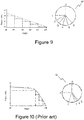
- One of the problems encountered in gas cookers is the difficulty to control the power level of the burners as the relation between the change of control knob's rotation angle and of the burner power lever is not linear. Referring to the prior art figure, there is a big angle range during which the power is decreasing a small value, followed by a small angle in which the power is decreasing considerably. This makes very difficult for a user to set intermediate power values by the control knob.
- There have been various attempts to solve above mentioned drawbacks. For instance,
US5906141 describes a device which permits locking of a control knob which can rotate around a cylindrical support and includes a lateral face with at least one first locking boss and a lateral face of a bracelet which has at least one second locking boss. The ring is movable in translation according to the axis between a locked position of the knob, in which the ring is prevented from rotating around the axis when the first and second bosses are engaged, and between a released position in which the first and second bosses are decoupled. -
EP1388872 describes an operating mechanism for rotational switch avoiding unintentional actuation. Accordingly, a variable output device mounted on a mounting unit with the operating shaft displaceable. -
TR2013/15150 - An object of the invention is to obtain a linear relation between the rotation angle of the control knob and the power level of an associated burner.
- Another object of the invention is to allow users to adjust power level of the burners more precisely.
- Another object of the invention is to allow users to give a tactile feeling of burner power level when rotating a control knob.
- In order to achieve above mentioned objects or those to be deducted from the specification, the present invention relates to a gas cooker having a cooker body with a front panel to which a control knob is mounted and a gas tap with a flow control member controlled by a gas tap shaft rotated by the rotation of said control knob. The invention is characterized in that it comprises a gear box having a primary shaft connected to the control knob, a secondary shaft extending parallel to said primary shaft, coupling means to connect output of the secondary shaft to the gas tap shaft, a primary gear group with plurality of gears inserted to the primary shaft in a shape coupling manner and as one adjacent to other, a secondary gear group with plurality of counter gears inserted to the secondary shaft in a shape coupling manner and as one adjacent to other and in a manner that each counter gear remains engaged with its corresponding gear in the primary gear group between predefined rotation angles of the control knob, and that the gear ratios between the gears and counter gears are so configured that the relation between the power level of the associated burner and rotation angle of the control knob becomes essentially linear at least when reducing the power of the burner from maximum power to a lower value by rotating the control knob.
- In a probable embodiment of the invention, each gear and counter gear comprises teeth which partly extend along their outer periphery so that the gear and its counter gear only remain engaged along a certain rotation angle range of the control knob.
- In another probable embodiment of the invention, the teeth of each gears and counter gears are aligned as outwardly eccentric with respect to the teeth of its adjacent gear and counter gear, respectively, so that the teeth and counter teeth only engage after the teeth of adjacent gear and counter gear disengage.
- In another probable embodiment of the invention, at least one of the gears or counter gears comprises a ring portion through which the primary or secondary shaft passes in a shape coupling manner and an extension or extension extending radially outwardly from the external surface of the ring portion and having said teeth on its distal side.
- In another probable embodiment of the invention, the gear ratios between the gears and counter gears are so configured that the relation between the power level of the associated burner and rotation angle of the control knob becomes essentially linear when reducing the power of the burner from maximum power to the minimum value.
- In another probable embodiment of the invention, the gear box comprises a first gear inserted to the primary shaft and having first teeth extending partly along its periphery and a first counter gear having first counter teeth extending partly along its periphery and inserted to the secondary shaft in a manner to engage with the first teeth during a first rotation angle range of the control knob.
- In another probable embodiment of the invention, the gear ratio between the first gear and the first counter gear is equal to 1. Thus, the rotation angle of the gas tap shaft is the same with that of the control knob at the beginning, i.e. opening the burner with full flame.
- In another probable embodiment of the invention, the gear box further comprises a second gear inserted to the primary shaft as adjacent to the first gear and having second teeth extending partly along its periphery and a second counter gear having second counter teeth extending partly along its periphery and inserted to the secondary shaft as adjacent to the first counter gear and in a manner to engage with the second teeth during a second rotation angle range of the control knob. Related to this, the gear ratio between the second gear and the second counter gear is higher than 1.
- In another probable embodiment of the invention, wherein the gear box further comprises a third gear inserted to the primary shaft as adjacent to the second gear and having third teeth extending partly along its periphery and a third counter gear having third counter teeth extending partly along its periphery and inserted to the secondary shaft as adjacent to the second counter gear and in a manner to engage with the third teeth during a third rotation angle range of the control knob. Related to this, the gear ratio between the third gear and the third counter gear is lower than 1.
- In another probable embodiment of the invention, the gear box further comprises a fourth gear inserted to the primary shaft as adjacent to the third gear and having fourth teeth extending partly along its periphery and a fourth counter gear having fourth counter teeth extending partly along its periphery and inserted to the secondary shaft as adjacent to the third counter gear and in a manner to engage with the fourth teeth during a fourth rotation angle range of the control knob.
- In another probable embodiment of the invention, the fourth gear ratio between the fourth gear and the fourth counter gear is lower than the third gear ratio.
- In another probable embodiment of the invention, the gear box further comprises a fifth gear inserted to the primary shaft as adjacent to the fourth gear and having fifth teeth extending partly along its periphery and a fifth counter gear having fifth counter teeth extending partly along its periphery and inserted to the secondary shaft as adjacent to the fourth counter gear and in a manner to engage with the fifth teeth during a fifth rotation angle range of the control knob.
- In another probable embodiment of the invention, the fifth gear ratio between the fifth gear and the fifth counter gear is lower than the fourth gear ratio.
- In another probable embodiment of the invention, the gear box further comprises a sixth gear inserted to the primary shaft as adjacent to the fifth gear and having sixth teeth extending partly along its periphery and a sixth counter gear having sixth counter teeth extending partly along its periphery and inserted to the secondary shaft as adjacent to the fifth counter gear and in a manner to engage with the sixth teeth during a sixth rotation angle range of the control knob.
- In another probable embodiment of the invention, the sixth gear ratio between the sixth gear and the sixth counter gear is lower than the fifth gear ratio.
- In another probable embodiment of the invention, the coupling means comprises a wheel gear inserted to a distal end of the primary shaft in a freely rotating manner and coupled to the gas tap shaft via its coupling extension and a counter wheel gear inserted to the secondary shaft in a shape coupling manner and in a manner to engage with the wheel gear.
- In another probable embodiment of the invention, the gear ratio between the wheel gear and the counter wheel gear is equal to 1.
- In another probable embodiment of the invention, the gear box further comprises a toothed section formed on the lateral side of the first gear facing to control knob and a ring inserted to the proximal end of the primary shaft as adjacent to the first gear in a manner that a projection on its lateral side facing to the first gear engages with teeth in the toothed section during rotation of the control knob.
-
-
Figure 1 illustrates a gas cooker equipped with the present invention -
Figure 2 illustrates exploded view of the gear box of the invention. -
Figure 3 illustrates step feeling arrangement of the invention. -
Figure 4 illustrates top view of the gear box of the invention. -
Figure 5, 6, 7 and 8 illustrate operation principle of the invention. -
Figure 9 illustrates a graphic showing the linear relation between the burner power level and control knob rotation angle. -
Figure 10 illustrates non-linear relation between the burner power level and control knob rotation angle in the prior art. - Preferred embodiments of the present invention will now be more particularly described by way of non-limiting examples with reference to the accompanying drawings.
-
Figure 1 illustrates a gas cooker (1) having a cooker body (10) and a front panel (11) to which plurality of control knobs (12) embodying the present invention is mounted. The gas cooker (1) also comprises gas taps each having a flow control member rotated by its respective gas tap shaft (not shown in figures). Accordingly, each control knob (12) is connected to one gas tap shaft in a shape coupling manner so that gas flow is adjusted when user rotates the control knob (12). In alternative embodiments, the control knobs of the present invention, however, might be applied to any other electric or gas fired device. - There is provided a gear box (40) between the control knob (12) and gas tap (not shown in figures). Said gear box (40) mainly comprises a primary gear group with plurality of gears rotating around a primary shaft (20) which is rotated by the control knob (12) and extending along a primary axis (A). The gear box (40) also comprises a secondary gear group with plurality of counter gears rotating around a secondary shaft (30), which forms the output of the gear box (40), after engaging with their corresponding gears in the primary gear group. The secondary shaft extends along a secondary axis (B) which is parallel to said primary axis (A).
- Gear ratio between each gear and counter gear in the gear box (40) is so configured that power level of the associated burner (13) changes linearly as the user rotates the control knob (12). On the other hand, teeth of each gear and its counter gear are configured so that they only engage during a certain rotation angle range of the control knob (12) once their adjacent gear and counter gear disengages. Thus, engagement duration of each gear and its counter defines one power level range adjusted by the rotation of the control knob (12).
- Referring to
figure 2 , in detail, the primary gear group comprises a first gear (60) having a first ring portion (61) and a first extension (62) extending radially outwardly from the external surface of the first ring portion (61). The primary shaft (20) passes through the first ring portion (61) in a shape coupling manner so that they rotate together. In a preferred embodiment, both the first ring portion (61) and the cross section of the primary shaft (20) are formed in C like form for enabling shape coupling. The first extension (62) is in quarter-circle form and comprises first teeth (621) on its arched side. - Correspondingly, the secondary gear group comprises a first counter gear (70) again having a first counter ring portion (71), through which the secondary shaft (30) passes in a shape coupling manner, and a first counter extension (72) in quarter-circle form with first counter teeth (721) thereon. The first counter gear (70) is almost in equivalent form with the first gear (60) and thus, no further structural details will be given to prevent unnecessary duplications. As understood, the distance between the center of a ring section and teeth of any gear or counter gear defines radius of the associated gear. For instance, in
figure 3 , R1 represents the radius of the first gear (60). Accordingly, since the first gear (60) and the first counter gear (70) have the same radius, the first gear ratio therebetween becomes 1. Thus, rotation amount obtained at output of the gear box (40) becomes the same as the input. - The total length of the first teeth (621) or correspondingly the first counter teeth (721) is higher than the radius of their respective ring portions (61, 71) so that the first teeth (621) and first counter teeth (721) remain engaged during a first rotation range of the control knob (12). Referring to
figure 9 , in a preferred embodiment, said first rotation angle range is, for instance, 90 degree. Accordingly, the user rotates the control knob (12) fromposition 0 where there is no flame in the associated burner toposition 1 where the burner provides a flame with maximum power. - In detail, the primary gear group further comprises a second gear (80) having a second ring portion (81) and a second extension (82) extending radially outwardly from the external surface of the second ring portion (81). The second gear (80) is inserted to the primary shaft (20) as adjacent to the first gear (60) via its second ring portion (81) in a shape coupling manner. The second extension (82) comprises second teeth (821) on its distal side and is in an elongated form to adequately increase the radius of the second gear.
- Correspondingly, the secondary gear group comprises a second counter gear (90) having a second counter ring portion (91) with second counter teeth (92) on the outer periphery of the ring portion so that the radius of the second counter gear (90) is kept as minimum as possible. The second counter gear (90) is inserted to the secondary shaft (30) as adjacent to the first counter gear (70) via its second counter ring portion (91) in a shape coupling manner.
- As also seen from the
figure 2 , since the radius of the second gear (80) is considerably higher than that of the second counter gear (90), the second gear ratio between the second gear (80) and second counter gear (90) becomes higher than 1. Accordingly, rotation amount at the output of the gear box (40), i.e. of the secondary shaft (30), becomes considerably higher than the input. - On the other hand, referring to
figure 5 , the second teeth (821) are aligned as outwardly eccentric with respect to the first teeth (621) and similarly the second counter (92) teeth are aligned as outwardly eccentric with respect to the first counter teeth (721) so that the second teeth and second counter teeth (821, 92) engages right after the first teeth (621) and the first counter teeth (721) disengages as illustrated infigure 6 . Related to this, the total length of the second teeth (821) or correspondingly the second counter teeth (92) is lower than the radius of their respective ring portions (81, 91) so that the second teeth (821) and second counter teeth (92) only remain engaged during a second rotation range of the control knob (12). Referring tofigure 9 , in a preferred embodiment, said second rotation angle is, for instance, 20 degree. Accordingly, the user rotates the control knob (12) fromposition 1 where there is full flame toposition 2 where the power level in the burner and thus flame size is a relatively reduced. - The primary gear group further comprises a third gear (100) having a third ring portion (101) and a third extension (102) extending radially outwardly from the external surface of its third ring portion (101). The third gear (100) is inserted to the primary shaft (20) as adjacent to the second gear (80) via its third ring portion (101) in a shape coupling manner. The third extension (102) comprises third teeth (1021) on its distal side and is not elongated to keep the radius of the third gear (100) relatively small.
- Correspondingly, the secondary gear group further comprises a third counter gear (110) having a third counter ring portion (111) and a third counter extension (112) extending radially outwardly from the external surface of the third counter ring portion (111). The third counter gear (110) is inserted to the secondary shaft (30) as adjacent to the second counter gear (90) via its third counter ring portion (111) in a shape coupling manner. The third counter extension (112) comprises third counter teeth (1121) on its distal side and is elongated to adequately increase the radius of the third counter gear (110).
- As also seen from the
figure 2 , since the radius of the third gear (100) is considerably lower than that of the third counter gear (110) the third gear ratio between the third gear (100) and third counter gear (110) becomes lower than 1. Accordingly, rotation amount at the output of the gear box (40) becomes considerably lower than the input. - On the other hand, referring to
figure 5 and 6 , the third teeth (1021) are aligned as outwardly eccentric with respect to the second teeth (821) and similarly the third counter teeth (1121) are aligned as outwardly eccentric with respect to the second counter teeth (92) so that they (1021, 1121) engage right after the second teeth (821) and the second counter teeth (92) disengages as illustrated infigure 7 . Related to this, the total length of the third teeth (1021) or correspondingly the third counter teeth (1121) is lower than radius of their respective ring portions (101, 111) or even lower than the teeth lengths of the second gear (80). Accordingly, the third teeth (1021) and third counter teeth (1121) only remain engaged during a third rotation range of the control knob (12). Referring tofigure 9 , in a preferred embodiment, said third rotation angle is, for instance, 20 degree. In such case, the user rotates the control knob (12) fromposition 2 to 3 where the power level in the burner is a bit more reduced. - The primary gear group further comprises a fourth gear (120) having a fourth ring portion (121) and a fourth extension (122) extending radially outwardly from the external surface of the fourth ring portion (121). The fourth gear (120) is inserted to the primary shaft (20) as adjacent to the third gear (100) via its fourth ring portion (121) in a shape coupling manner. The fourth extension (122) comprises fourth teeth (1221) on its distal side and is not elongated to keep the radius of the fourth gear (120) relatively small.
- Correspondingly, the secondary gear group further comprises a fourth counter gear (130) having a fourth counter ring portion (131) and a fourth counter extension (132) extending radially outwardly from the external surface of its fourth counter ring portion (131). The fourth counter gear (130) is inserted to the secondary shaft (30) as adjacent to the third counter gear (110) via its fourth counter ring portion (131) in a shape coupling manner. The fourth counter extension (132) comprises fourth counter teeth (1321) on its distal side and is elongated to adequately increase the radius of the fourth counter gear (130).
- As also seen from the
figure 2 , the radius of the fourth gear (120) is so lower than that of the fourth counter gear (130) that the fourth gear ratio becomes even lower than the third gear ratio. Accordingly, rotation amount at the output of the gear box (40) is a bit more reduced compared to previous stage. - On the other hand, referring to
figure 6 , the fourth teeth (1221) are aligned as outwardly eccentric with respect to the third teeth (1021) and similarly the fourth counter teeth (1321) are aligned as outwardly eccentric with respect to the third counter teeth (1121) so that fourth teeth (1221) and fourth counter teeth (1321) engages right after the third teeth (1021) and the third counter teeth (1121) disengages as illustrated infigure 8 . Related to this, the total length of the fourth teeth (1221) or correspondingly the fourth counter teeth (1321) is lower than radius of their respective ring portions (121, 131) or even equal to or lower than the teeth lengths of the third gear (100). Accordingly, the fourth teeth (1221) and fourth counter teeth (1321) only remain engaged during a fourth rotation range of the control knob (12). Referring tofigure 9 , in a preferred embodiment, said fourth rotation angle is, for instance, 20 degree. In such case, the user rotates the control knob (12) fromposition 3 to 4 where the power level in the burner (13) is a bit more reduced. - The primary gear group further comprises a fifth gear (140) having a fifth ring portion (141) and a fifth extension (142) extending radially outwardly from the external surface of the fifth ring portion (141). The fifth gear (140) is inserted to the primary shaft (20) as adjacent to the fourth gear (120) via its fifth ring portion (141) in a shape coupling manner. The fifth extension (142) comprises fifth teeth (1421) on its distal side and is not elongated to keep the radius of the fifth gear (140) relatively small.
- Correspondingly, the secondary gear group further comprises a fifth counter gear (150) having a fifth counter ring portion (151) and a fifth counter extension (152) extending radially outwardly from the external surface of its fifth counter ring portion (151). The fifth counter gear (150) is inserted to the secondary shaft (30) as adjacent to the fourth counter gear (130) via its fifth counter ring portion (151) in a shape coupling manner. The fifth counter extension (152) comprises fifth counter teeth (1521) on its distal side and is elongated to adequately increase the radius of the fifth counter gear (150).
- As also seen from the
figure 2 , the radius of the fifth gear (140) is so lower than that of the fifth counter gear (150) that the fifth gear ratio becomes even lower than the fourth gear ratio. Accordingly, rotation amount at the output of the gear box (40) is a bit more reduced compared to previous stage. - On the other hand, referring to
figure 6 , the fifth teeth (1421) are aligned as outwardly eccentric with respect to the fourth teeth (1221) and similarly the fifth counter teeth (1521) are aligned as outwardly eccentric with respect to the fourth counter teeth (1321) so that they engages (1421, 1521) right after the fourth teeth (1221) and the fourth counter teeth (1321) disengages. Related to this, the total length of the fifth teeth (1421) or correspondingly the fifth counter teeth (1521) is lower than radius of their respective ring portions (141, 151) or even equal to or lower than the teeth lengths of the fourth gear (120). Accordingly, the fifth teeth (1421) and fifth counter teeth (1521) only remain engaged during a fifth rotation range of the control knob (12). Referring tofigure 9 , in a preferred embodiment, said fourth rotation angle is, for instance, 20 degree. In such case, the user rotates the control knob (12) fromposition 4 to 5 where the power level in the burner (13) is a bit more reduced. - The primary gear group further comprises a sixth gear (160) having a sixth ring portion (161) with sixth teeth (162) on the outer periphery of its sixth ring portion (161) so that the radius of the sixth gear (160) is kept as minimum as possible. The sixth gear (160) is inserted to the primary shaft (20) as adjacent to the fifth gear (140) via its sixth ring portion (161) in a shape coupling manner.
- Correspondingly, the secondary gear group further comprises a sixth counter gear (170) having a sixth counter ring portion (171) and a sixth counter extension (172) extending radially outwardly from the external surface of its sixth counter ring portion (171). The sixth counter gear (170) is inserted to the secondary shaft (30) as adjacent to the fifth counter gear (150) via its sixth counter ring portion (171) in a shape coupling manner. The sixth counter extension (172) comprises sixth counter teeth (1721) on its distal side and is elongated to adequately increase the radius of the sixth counter gear (170).
- As also seen from the
figure 2 , the radius of the sixth gear (160) is so lower than that of the sixth counter gear (170) that the sixth gear ratio becomes even lower than the fifth gear ratio. Accordingly, rotation amount at the output of the gear box (40) is a bit more reduced compared to previous stage. - On the other hand, referring to
figure 6 , the sixth teeth (162) are aligned as outwardly eccentric with respect to the fifth teeth (1421)and similarly the sixth counter teeth (1721)are aligned as outwardly eccentric with respect to the fifth counter teeth (1521) so that they (162, 1721) engage right after the fifth teeth (1421) and the fifth counter teeth (1521) disengages. Related to this, the total length of the sixth teeth (162) or correspondingly the sixth counter teeth (1721) is lower than radius of their respective ring portions (161, 171) or even equal to or lower than then the teeth lengths of the fifth gear (140). Accordingly, the sixth teeth (162) and sixth counter teeth (1721) only remain engaged during a sixth rotation range of the control knob (12). Referring tofigure 9 , in a preferred embodiment, said sixth rotation angle is, for instance, 20 degree. In such case, the user rotates the control knob (12) fromposition 5 to 6 where the power level in the burner (13) is minimum. - As seen from the above explanations and associated figures, each gear and counter gear in the gear box (40) have teeth partly extending along their periphery, as different from standard wheel type gears, so that they only remain engaged along a certain rotation angle range of the control knob (12). To obtain such a gear form, preferably, gears and counter gears are obtained by removing certain portions of a wheel type gear, which is an easy to find component, by metal processing equipment. In another alternative embodiment, all the gears and counter gears can be made of a plastic material. In such case, injection molding technique may be preferred to produce plastic gears or counter gears.
- It is apparent for a skilled person in the art that the number of the gear or counter gears and thus relevant parameters such as gear ratio, teeth lengths or their alignment can be changed depending on requirements defined by users or by home appliance to which the present invention is to be applied.
- Referring to
figure 2 , the primary gear group further comprises a wheel gear (180) which is provided as adjacent to the sixth gear (160) on the primary shaft (20) and inserted to the primary shaft (20) in a freely rotating manner via its circular shaft opening. The wheel gear (180) comprises a coupling extension (181) on its circular side facing to gas tap. A tap shaft connection (200), which is coupled to the gas tap shaft, is attached the said coupling extension (181) in a shape coupling manner so that gas tap shaft rotates along with the rotation of the wheel gear (180). - Correspondingly, the secondary gear group further comprises a counter wheel gear (190) which is provided as adjacent to the sixth counter gear (170) on the secondary shaft (30) and inserted to the secondary shaft (30) in a shape coupling manner via its C shaped shaft opening. The gear ratio between the wheel gear (180) and counter wheel gear (190) is 1. Accordingly, the wheel gear (180) only rotates along with the counter wheel gear (190) so that the rotational movement in the secondary shaft (30) is transferred to the gas tap shaft.
- The invention also provides step feeling to the user when rotating the control knob (12). Referring to
figure 3 , to achieve this tactile effect, a ring (50) is inserted to the primary shaft (20) before the first gear (60). The ring (50) has a projection (51) on its lateral surface facing to the first ring portion (61) of the first gear (60). Correspondingly, the first ring portion (61) is provided with a recess (611) and a toothed section (612) spaced apart from the recess (611) on the annular face of the first ring portion (61). The projection (51) engages with the recess (611) and then the toothed section (612) as the user rotates the control knob (12) between power adjustment levels from 0 to 6. Number of teeth in the toothed section (612) defines number of steps to be felt by the user. - Referring to
figure 3 and 4 , the periphery of the ring (50) also comprises a flat face (52) which abuts to a fixing wall (42) provided inside the casing (41) of the gear box (40). Thank to this, rotation of the ring (50) is prevented inside the casing (41) while the ring (50) is axially movable on the primary shaft (20). Related to this, a pressing spring (43) presses the ring (50) towards the first gear (60) in the primary axis (A) direction and the ring (50) retracts when the projection (51) coincides with teeth in said toothed section (612) or is released from said recess (611). The primary shaft (20) also comprises an abutment to which the ring (50) is rested to limit its backward movement towards the control knob (12). In a preferred embodiment, referring tofigure 5 , atposition 0, the projection (51) is inside the recess (611) and then is released from the recess (611) as the user rotates the control knob (12) toposition 1. Referring tofigures 6 to 8 , betweenpositions - It will be readily apparent that modifications of the embodiments hereinbefore described are possible. In particular, although numerous features are shown in combination, these features can also be taken into consideration individually and also combined into any feasible further combinations.
-
- 1 Gas cooker
- 10 Cooker body
- 11 Front panel
- 12 Control knob
- 13 Burner
- 20 Primary shaft
- 30 Secondary shaft
- 40 Gear box
- 41 Casing
- 42 Fixing wall
- 43 Pressing Spring
- 50 Ring
- 51 Projection
- 52 Flat face
- 60 First gear
- 61 First ring portion
- 611 Recess
- 612 Toothed section
- 62 First extension
- 621 First teeth
- 70 First counter gear
- 71 First counter ring portion
- 72 First counter extension
- 721 First counter teeth
- 80 Second gear
- 81 Second ring portion
- 82 Second Extension
- 821 Second teeth
- 90 Second counter gear
- 91 Second counter ring portion
- 92 Second counter teeth
- 100 Third gear
- 101 Third ring portion
- 102 Third extension
- 1021 Third teeth
- 110 Third counter gear
- 111 Third counter ring portion
- 112 Third counter extension
- 1121 Third counter teeth
- 120 Fourth gear
- 121 Fourth ring portion
- 122 Fourth extension
- 1221 Fourth teeth
- 130 Fourth counter gear
- 131 Fourth counter ring portion
- 132 Fourth counter extension
- 1321 Fourth counter teeth
- 140 Fifth gear
- 141 Fifth ring portion
- 142 Fifth extension
- 1421 Fifth teeth
- 150 Fifth counter gear
- 151 Fifth counter ring portion
- 152 Fifth counter extension
- 1521 Fifth counter teeth
- 160 Sixth gear
- 161 Sixth ring portion
- 162 Sixth teeth
- 170 Sixth counter gear
- 171 Sixth counter ring portion
- 172 Sixth counter extension
- 1721 Sixth counter teeth
- 180 Wheel gear
- 181 Coupling extension
- 190 Counter wheel gear
- 200 Tap shaft connection
- A: Primary axis
- B: Secondary axis
- R1 : Radius of the first gear
Claims (20)
- A gas cooker (1) having a cooker body (10) with a front panel (11) to which a control knob (12) is mounted and a gas tap with a flow control member controlled by a gas tap shaft rotated by the rotation of said control knob (12), characterized in that it comprises a gear box (40) having a primary shaft (20) connected to the control knob (12), a secondary shaft (30) extending parallel to said primary shaft (20), coupling means to connect output of the secondary shaft (30) to the gas tap shaft, a primary gear group with plurality of gears inserted to the primary shaft (20) in a shape coupling manner and as one adjacent to other, a secondary gear group with plurality of counter gears inserted to the secondary shaft (30) in a shape coupling manner and as one adjacent to other and in a manner that each counter gear remains engaged with its corresponding gear in the primary gear group between predefined rotation angles of the control knob (12), and that the gear ratios between the gears and counter gears are so configured that the relation between the power level of the associated burner and rotation angle of the control knob (12) becomes essentially linear at least when reducing the power of the burner from maximum power to a lower value by rotating the control knob (12).
- A gas cooker (1) according to claim 1, wherein each gear and counter gear comprises teeth which partly extend along their outer periphery so that the gear and its counter gear only remain engaged along a certain rotation angle range of the control knob.
- A gas cooker (1) according to claim 1 or 2, wherein the teeth of each gears and counter gears are aligned as outwardly eccentric with respect to the teeth of its adjacent gear and counter gear, respectively, so that the teeth and counter teeth only engage after the teeth of adjacent gear and counter gear disengage.
- A gas cooker (1) according to any of the preceding claims, wherein at least one of the gears or counter gears comprises a ring portion through which the primary or secondary shaft (20, 30) passes in a shape coupling manner and an extension or extension extending radially outwardly from the external surface of the ring portion and having said teeth on its distal side.
- A gas cooker (1) according to any of the preceding claims, wherein the gear ratios between the gears and counter gears are so configured that the relation between the power level of the associated burner and rotation angle of the control knob (12) becomes essentially linear when reducing the power of the burner from maximum power to minimum value.
- A gas cooker (1) according to claim 1, wherein the gear box (40) comprises a first gear (60) inserted to the primary shaft (20) and having first teeth (621) extending partly along its periphery and a first counter gear (70) having first counter teeth (721) extending partly along its periphery and inserted to the secondary shaft (30) in a manner to engage with the first teeth (621) during a first rotation angle range of the control knob (12).
- A gas cooker (1) according to claim 6, wherein the gear ratio between the first gear (60) and the first counter gear (70) is equal to 1.
- A gas cooker (1) according to claim 6, wherein the gear box (40) further comprises a second gear (80) inserted to the primary shaft (20) as adjacent to the first gear (60) and having second teeth (821) extending partly along its periphery and a second counter gear (90) having second counter teeth (92) extending partly along its periphery and inserted to the secondary shaft (30) as adjacent to the first counter gear (70) and in a manner to engage with the second teeth (821) during a second rotation angle range of the control knob (12).
- A gas cooker (1) according to claim 8, wherein the gear ratio between the second gear (80) and the second counter gear (90) is higher than 1.
- A gas cooker (1) according to claim 8, wherein the gear box (40) further comprises a third gear (100) inserted to the primary shaft (20) as adjacent to the second gear (80) and having third teeth (1021) extending partly along its periphery and a third counter gear (110) having third counter teeth (1121) extending partly along its periphery and inserted to the secondary shaft (30) as adjacent to the second counter gear (90) and in a manner to engage with the third teeth (1021) during a third rotation angle range of the control knob (12).
- A gas cooker (1) according to claim 10, wherein the gear ratio between the third gear (100) and the third counter gear (110) is lower than 1.
- A gas cooker (1) according to claim 10, wherein the gear box (40) further comprises a fourth gear (120) inserted to the primary shaft (20) as adjacent to the third gear (100) and having fourth teeth (1221) extending partly along its periphery and a fourth counter gear (130) having fourth counter teeth (1321) extending partly along its periphery and inserted to the secondary shaft (30) as adjacent to the third counter gear (110) and in a manner to engage with the fourth teeth (120) during a fourth rotation angle range of the control knob (12).
- A gas cooker (1) according to claim 12, wherein the fourth gear ratio between the fourth gear (120) and the fourth counter gear (130) is lower than the third gear ratio.
- A gas cooker (1) according to claim 12, wherein the gear box (40) further comprises a fifth gear (140) inserted to the primary shaft (20) as adjacent to the fourth gear (120) and having fifth teeth (1421) extending partly along its periphery and a fifth counter gear (150) having fifth counter teeth (1521) extending partly along its periphery and inserted to the secondary shaft (30) as adjacent to the fourth counter gear (130) and in a manner to engage with the fifth teeth (1421) during a fifth rotation angle range of the control knob (12).
- A gas cooker (1) according to claim 14, wherein the fifth gear ratio between the fifth gear (140) and the fifth counter gear (150) is lower than the fourth gear ratio.
- A gas cooker (1) according to claim 14, wherein the gear box (40) further comprises a sixth gear (160) inserted to the primary shaft (20) as adjacent to the fifth gear (140) and having sixth teeth (162) extending partly along its periphery and a sixth counter gear (170) having sixth counter teeth (1721) extending partly along its periphery and inserted to the secondary shaft (30) as adjacent to the fifth counter gear (150) and in a manner to engage with the sixth teeth (162) during a sixth rotation angle range of the control knob (12).
- A gas cooker (1) according to claim 16, wherein the sixth gear ratio between the sixth gear (160) and the sixth counter gear (170) is lower than the fifth gear ratio.
- A gas cooker (1) according to claim 1, wherein the coupling means comprises a wheel gear (180) inserted to a distal end of the primary shaft (20) in a freely rotating manner and coupled to the gas tap shaft via its coupling extension (181) and a counter wheel gear (190) inserted to the secondary shaft (30) in a shape coupling manner and in a manner to engage with the wheel gear (180).
- A gas cooker (1) according to claim 18, wherein the gear ratio between the wheel gear (180) and the counter wheel gear (190) is equal to 1.
- A gas cooker (1) according to claim 1, wherein the gear box (40) further comprises a toothed section (612) formed on the lateral side of the first gear (60) facing to control knob (12) and a ring (50) inserted to the proximal end of the primary shaft (20) as adjacent to the first gear (60) in a manner that a projection (51) on its lateral side facing to the first gear (60) engages with teeth in the toothed section (612) during rotation of the control knob (12).
Applications Claiming Priority (1)
| Application Number | Priority Date | Filing Date | Title |
|---|---|---|---|
| TR2016/11375A TR201611375A2 (en) | 2016-08-12 | 2016-08-12 | A Control Knob Equipped With a Gear Box For Controlling Power Level Of a Burner in a Gas Cooker |
Publications (2)
| Publication Number | Publication Date |
|---|---|
| EP3282194A1 true EP3282194A1 (en) | 2018-02-14 |
| EP3282194B1 EP3282194B1 (en) | 2019-02-20 |
Family
ID=59485157
Family Applications (1)
| Application Number | Title | Priority Date | Filing Date |
|---|---|---|---|
| EP17182520.1A Active EP3282194B1 (en) | 2016-08-12 | 2017-07-21 | A control knob equipped with a gear box for controlling power level of a burner in a gas cooker |
Country Status (3)
| Country | Link |
|---|---|
| EP (1) | EP3282194B1 (en) |
| CN (1) | CN107726376B (en) |
| TR (1) | TR201611375A2 (en) |
Citations (9)
| Publication number | Priority date | Publication date | Assignee | Title |
|---|---|---|---|---|
| US3606612A (en) * | 1969-10-20 | 1971-09-20 | Columbia Gas Syst | Gas burner and control |
| US5740789A (en) * | 1995-08-21 | 1998-04-21 | Chang; Che Yuan | Modification of the gas stove by installing oxygen booster |
| US5906141A (en) | 1996-02-28 | 1999-05-25 | Dosapro-Milton Roy S.A. | Locking device for the angular position of a control knob |
| EP1388872A2 (en) | 2002-08-07 | 2004-02-11 | Matsushita Electric Industrial Co., Ltd. | Operating mechanism for rotational switch avoiding unintentional actuation |
| JP3789382B2 (en) * | 2002-04-05 | 2006-06-21 | リンナイ株式会社 | Gas flow control device |
| KR20080000325U (en) * | 2008-02-21 | 2008-03-19 | 김태한 | Gas valve knob |
| US7513247B2 (en) * | 2003-01-13 | 2009-04-07 | Bsh Bosch Und Siemens Hausgeraete Gmbh | Gas cooking equipment and method for producing gas cooking equipment |
| DE102009012290A1 (en) * | 2009-03-11 | 2010-09-16 | Heatec Thermotechnik Gmbh | Gas valve module for gas valve arrangement, has module housing which has base body and gas-tight housing cover connected with base body, and gas supply channel is provided in base body |
| US8869835B1 (en) * | 2012-04-17 | 2014-10-28 | Burner Systems International, Inc. | Dual valve |
Family Cites Families (4)
| Publication number | Priority date | Publication date | Assignee | Title |
|---|---|---|---|---|
| CN2260252Y (en) * | 1996-07-31 | 1997-08-20 | 梁学忠 | Multi-stage adjusting valve for domestic gas range |
| CN2329876Y (en) * | 1998-05-22 | 1999-07-21 | 宁波金欧厨具有限公司 | Firepower section change-over positioning mechanism for gas range |
| EP2889539B1 (en) * | 2013-12-24 | 2017-01-11 | BSH Hausgeräte GmbH | A cooking apparatus which includes a gas tap equipped with a tactile feedback device |
| CN204115014U (en) * | 2014-10-14 | 2015-01-21 | 樱花卫厨(中国)股份有限公司 | Paragraph type fire power regulator |
-
2016
- 2016-08-12 TR TR2016/11375A patent/TR201611375A2/en unknown
-
2017
- 2017-07-21 EP EP17182520.1A patent/EP3282194B1/en active Active
- 2017-08-11 CN CN201710685945.5A patent/CN107726376B/en not_active Expired - Fee Related
Patent Citations (9)
| Publication number | Priority date | Publication date | Assignee | Title |
|---|---|---|---|---|
| US3606612A (en) * | 1969-10-20 | 1971-09-20 | Columbia Gas Syst | Gas burner and control |
| US5740789A (en) * | 1995-08-21 | 1998-04-21 | Chang; Che Yuan | Modification of the gas stove by installing oxygen booster |
| US5906141A (en) | 1996-02-28 | 1999-05-25 | Dosapro-Milton Roy S.A. | Locking device for the angular position of a control knob |
| JP3789382B2 (en) * | 2002-04-05 | 2006-06-21 | リンナイ株式会社 | Gas flow control device |
| EP1388872A2 (en) | 2002-08-07 | 2004-02-11 | Matsushita Electric Industrial Co., Ltd. | Operating mechanism for rotational switch avoiding unintentional actuation |
| US7513247B2 (en) * | 2003-01-13 | 2009-04-07 | Bsh Bosch Und Siemens Hausgeraete Gmbh | Gas cooking equipment and method for producing gas cooking equipment |
| KR20080000325U (en) * | 2008-02-21 | 2008-03-19 | 김태한 | Gas valve knob |
| DE102009012290A1 (en) * | 2009-03-11 | 2010-09-16 | Heatec Thermotechnik Gmbh | Gas valve module for gas valve arrangement, has module housing which has base body and gas-tight housing cover connected with base body, and gas supply channel is provided in base body |
| US8869835B1 (en) * | 2012-04-17 | 2014-10-28 | Burner Systems International, Inc. | Dual valve |
Also Published As
| Publication number | Publication date |
|---|---|
| CN107726376B (en) | 2020-01-17 |
| CN107726376A (en) | 2018-02-23 |
| TR201611375A2 (en) | 2018-02-21 |
| EP3282194B1 (en) | 2019-02-20 |
Similar Documents
| Publication | Publication Date | Title |
|---|---|---|
| US5662465A (en) | Controlling flow of fuel gas to a burner | |
| US10379569B2 (en) | Multi-function appliance knob incorporating multiple rotation modulating mechanisms | |
| US4037490A (en) | Two-step control knob operation | |
| EP3087320B1 (en) | A cooking appliance which includes a gas tap equipped with a tactile feedback device | |
| EP3505829A1 (en) | A cooking appliance having a control knob | |
| EP3462092A1 (en) | A cooking device having a control knob | |
| EP3192930B1 (en) | Fitting with extendible sprinkler | |
| EP3282194B1 (en) | A control knob equipped with a gear box for controlling power level of a burner in a gas cooker | |
| EP3845816B1 (en) | Cooking apparatus with a knob assembly | |
| CN112944009A (en) | Plug valve and gas stove | |
| EP2889539B1 (en) | A cooking apparatus which includes a gas tap equipped with a tactile feedback device | |
| EP2857920B1 (en) | A thermostatic head for a valve | |
| EP2889540B1 (en) | A cooking appliance which includes a gas tap button equipped with tactile feedback effect | |
| WO2018121951A1 (en) | Cooker device comprising a button | |
| EP3312485B1 (en) | A temperature limiting adjustable device | |
| EP2741007B1 (en) | Ignition switch assembly for a gas tap | |
| EP3273321B1 (en) | A rotary control knob of a gas cooker | |
| EP2896886A1 (en) | Gas cooktop and appliance comprising such a gas cooktop | |
| CN108319125B (en) | Timer structure for electric appliance | |
| EP2868978A1 (en) | A domestic appliance fitted with a button socket | |
| EP3847397B1 (en) | A gas cooker comprising a knob | |
| US20180045418A1 (en) | Gas cooktop with defined simmer settings | |
| US20260126178A1 (en) | Control Knob For Cooking Appliance | |
| KR100888464B1 (en) | The gas burner in which able to control fire adjustment at many direction | |
| CN115435137B (en) | Flow control valves and household appliances |
Legal Events
| Date | Code | Title | Description |
|---|---|---|---|
| PUAI | Public reference made under article 153(3) epc to a published international application that has entered the european phase |
Free format text: ORIGINAL CODE: 0009012 |
|
| STAA | Information on the status of an ep patent application or granted ep patent |
Free format text: STATUS: THE APPLICATION HAS BEEN PUBLISHED |
|
| AK | Designated contracting states |
Kind code of ref document: A1 Designated state(s): AL AT BE BG CH CY CZ DE DK EE ES FI FR GB GR HR HU IE IS IT LI LT LU LV MC MK MT NL NO PL PT RO RS SE SI SK SM TR |
|
| AX | Request for extension of the european patent |
Extension state: BA ME |
|
| STAA | Information on the status of an ep patent application or granted ep patent |
Free format text: STATUS: REQUEST FOR EXAMINATION WAS MADE |
|
| 17P | Request for examination filed |
Effective date: 20180814 |
|
| GRAP | Despatch of communication of intention to grant a patent |
Free format text: ORIGINAL CODE: EPIDOSNIGR1 |
|
| RBV | Designated contracting states (corrected) |
Designated state(s): AL AT BE BG CH CY CZ DE DK EE ES FI FR GB GR HR HU IE IS IT LI LT LU LV MC MK MT NL NO PL PT RO RS SE SI SK SM TR |
|
| STAA | Information on the status of an ep patent application or granted ep patent |
Free format text: STATUS: GRANT OF PATENT IS INTENDED |
|
| INTG | Intention to grant announced |
Effective date: 20180920 |
|
| GRAS | Grant fee paid |
Free format text: ORIGINAL CODE: EPIDOSNIGR3 |
|
| GRAA | (expected) grant |
Free format text: ORIGINAL CODE: 0009210 |
|
| STAA | Information on the status of an ep patent application or granted ep patent |
Free format text: STATUS: THE PATENT HAS BEEN GRANTED |
|
| AK | Designated contracting states |
Kind code of ref document: B1 Designated state(s): AL AT BE BG CH CY CZ DE DK EE ES FI FR GB GR HR HU IE IS IT LI LT LU LV MC MK MT NL NO PL PT RO RS SE SI SK SM TR |
|
| REG | Reference to a national code |
Ref country code: GB Ref legal event code: FG4D |
|
| REG | Reference to a national code |
Ref country code: CH Ref legal event code: EP |
|
| REG | Reference to a national code |
Ref country code: DE Ref legal event code: R096 Ref document number: 602017002210 Country of ref document: DE |
|
| REG | Reference to a national code |
Ref country code: AT Ref legal event code: REF Ref document number: 1098690 Country of ref document: AT Kind code of ref document: T Effective date: 20190315 |
|
| REG | Reference to a national code |
Ref country code: IE Ref legal event code: FG4D |
|
| REG | Reference to a national code |
Ref country code: SE Ref legal event code: TRGR |
|
| REG | Reference to a national code |
Ref country code: LT Ref legal event code: MG4D Ref country code: NL Ref legal event code: MP Effective date: 20190220 |
|
| PG25 | Lapsed in a contracting state [announced via postgrant information from national office to epo] |
Ref country code: LT Free format text: LAPSE BECAUSE OF FAILURE TO SUBMIT A TRANSLATION OF THE DESCRIPTION OR TO PAY THE FEE WITHIN THE PRESCRIBED TIME-LIMIT Effective date: 20190220 Ref country code: FI Free format text: LAPSE BECAUSE OF FAILURE TO SUBMIT A TRANSLATION OF THE DESCRIPTION OR TO PAY THE FEE WITHIN THE PRESCRIBED TIME-LIMIT Effective date: 20190220 Ref country code: PT Free format text: LAPSE BECAUSE OF FAILURE TO SUBMIT A TRANSLATION OF THE DESCRIPTION OR TO PAY THE FEE WITHIN THE PRESCRIBED TIME-LIMIT Effective date: 20190620 Ref country code: NO Free format text: LAPSE BECAUSE OF FAILURE TO SUBMIT A TRANSLATION OF THE DESCRIPTION OR TO PAY THE FEE WITHIN THE PRESCRIBED TIME-LIMIT Effective date: 20190520 |
|
| PG25 | Lapsed in a contracting state [announced via postgrant information from national office to epo] |
Ref country code: HR Free format text: LAPSE BECAUSE OF FAILURE TO SUBMIT A TRANSLATION OF THE DESCRIPTION OR TO PAY THE FEE WITHIN THE PRESCRIBED TIME-LIMIT Effective date: 20190220 Ref country code: NL Free format text: LAPSE BECAUSE OF FAILURE TO SUBMIT A TRANSLATION OF THE DESCRIPTION OR TO PAY THE FEE WITHIN THE PRESCRIBED TIME-LIMIT Effective date: 20190220 Ref country code: RS Free format text: LAPSE BECAUSE OF FAILURE TO SUBMIT A TRANSLATION OF THE DESCRIPTION OR TO PAY THE FEE WITHIN THE PRESCRIBED TIME-LIMIT Effective date: 20190220 Ref country code: BG Free format text: LAPSE BECAUSE OF FAILURE TO SUBMIT A TRANSLATION OF THE DESCRIPTION OR TO PAY THE FEE WITHIN THE PRESCRIBED TIME-LIMIT Effective date: 20190520 Ref country code: LV Free format text: LAPSE BECAUSE OF FAILURE TO SUBMIT A TRANSLATION OF THE DESCRIPTION OR TO PAY THE FEE WITHIN THE PRESCRIBED TIME-LIMIT Effective date: 20190220 Ref country code: IS Free format text: LAPSE BECAUSE OF FAILURE TO SUBMIT A TRANSLATION OF THE DESCRIPTION OR TO PAY THE FEE WITHIN THE PRESCRIBED TIME-LIMIT Effective date: 20190620 Ref country code: GR Free format text: LAPSE BECAUSE OF FAILURE TO SUBMIT A TRANSLATION OF THE DESCRIPTION OR TO PAY THE FEE WITHIN THE PRESCRIBED TIME-LIMIT Effective date: 20190521 |
|
| REG | Reference to a national code |
Ref country code: AT Ref legal event code: MK05 Ref document number: 1098690 Country of ref document: AT Kind code of ref document: T Effective date: 20190220 |
|
| PG25 | Lapsed in a contracting state [announced via postgrant information from national office to epo] |
Ref country code: SK Free format text: LAPSE BECAUSE OF FAILURE TO SUBMIT A TRANSLATION OF THE DESCRIPTION OR TO PAY THE FEE WITHIN THE PRESCRIBED TIME-LIMIT Effective date: 20190220 Ref country code: EE Free format text: LAPSE BECAUSE OF FAILURE TO SUBMIT A TRANSLATION OF THE DESCRIPTION OR TO PAY THE FEE WITHIN THE PRESCRIBED TIME-LIMIT Effective date: 20190220 Ref country code: DK Free format text: LAPSE BECAUSE OF FAILURE TO SUBMIT A TRANSLATION OF THE DESCRIPTION OR TO PAY THE FEE WITHIN THE PRESCRIBED TIME-LIMIT Effective date: 20190220 Ref country code: AL Free format text: LAPSE BECAUSE OF FAILURE TO SUBMIT A TRANSLATION OF THE DESCRIPTION OR TO PAY THE FEE WITHIN THE PRESCRIBED TIME-LIMIT Effective date: 20190220 Ref country code: CZ Free format text: LAPSE BECAUSE OF FAILURE TO SUBMIT A TRANSLATION OF THE DESCRIPTION OR TO PAY THE FEE WITHIN THE PRESCRIBED TIME-LIMIT Effective date: 20190220 Ref country code: RO Free format text: LAPSE BECAUSE OF FAILURE TO SUBMIT A TRANSLATION OF THE DESCRIPTION OR TO PAY THE FEE WITHIN THE PRESCRIBED TIME-LIMIT Effective date: 20190220 Ref country code: ES Free format text: LAPSE BECAUSE OF FAILURE TO SUBMIT A TRANSLATION OF THE DESCRIPTION OR TO PAY THE FEE WITHIN THE PRESCRIBED TIME-LIMIT Effective date: 20190220 |
|
| REG | Reference to a national code |
Ref country code: DE Ref legal event code: R097 Ref document number: 602017002210 Country of ref document: DE |
|
| PG25 | Lapsed in a contracting state [announced via postgrant information from national office to epo] |
Ref country code: SM Free format text: LAPSE BECAUSE OF FAILURE TO SUBMIT A TRANSLATION OF THE DESCRIPTION OR TO PAY THE FEE WITHIN THE PRESCRIBED TIME-LIMIT Effective date: 20190220 Ref country code: PL Free format text: LAPSE BECAUSE OF FAILURE TO SUBMIT A TRANSLATION OF THE DESCRIPTION OR TO PAY THE FEE WITHIN THE PRESCRIBED TIME-LIMIT Effective date: 20190220 |
|
| PLBE | No opposition filed within time limit |
Free format text: ORIGINAL CODE: 0009261 |
|
| STAA | Information on the status of an ep patent application or granted ep patent |
Free format text: STATUS: NO OPPOSITION FILED WITHIN TIME LIMIT |
|
| PG25 | Lapsed in a contracting state [announced via postgrant information from national office to epo] |
Ref country code: AT Free format text: LAPSE BECAUSE OF FAILURE TO SUBMIT A TRANSLATION OF THE DESCRIPTION OR TO PAY THE FEE WITHIN THE PRESCRIBED TIME-LIMIT Effective date: 20190220 |
|
| 26N | No opposition filed |
Effective date: 20191121 |
|
| REG | Reference to a national code |
Ref country code: DE Ref legal event code: R119 Ref document number: 602017002210 Country of ref document: DE |
|
| PG25 | Lapsed in a contracting state [announced via postgrant information from national office to epo] |
Ref country code: MC Free format text: LAPSE BECAUSE OF FAILURE TO SUBMIT A TRANSLATION OF THE DESCRIPTION OR TO PAY THE FEE WITHIN THE PRESCRIBED TIME-LIMIT Effective date: 20190220 Ref country code: SI Free format text: LAPSE BECAUSE OF FAILURE TO SUBMIT A TRANSLATION OF THE DESCRIPTION OR TO PAY THE FEE WITHIN THE PRESCRIBED TIME-LIMIT Effective date: 20190220 |
|
| REG | Reference to a national code |
Ref country code: BE Ref legal event code: MM Effective date: 20190731 |
|
| PG25 | Lapsed in a contracting state [announced via postgrant information from national office to epo] |
Ref country code: DE Free format text: LAPSE BECAUSE OF NON-PAYMENT OF DUE FEES Effective date: 20200201 |
|
| PG25 | Lapsed in a contracting state [announced via postgrant information from national office to epo] |
Ref country code: BE Free format text: LAPSE BECAUSE OF NON-PAYMENT OF DUE FEES Effective date: 20190731 Ref country code: LU Free format text: LAPSE BECAUSE OF NON-PAYMENT OF DUE FEES Effective date: 20190721 |
|
| PG25 | Lapsed in a contracting state [announced via postgrant information from national office to epo] |
Ref country code: IE Free format text: LAPSE BECAUSE OF NON-PAYMENT OF DUE FEES Effective date: 20190721 |
|
| REG | Reference to a national code |
Ref country code: CH Ref legal event code: PL |
|
| PG25 | Lapsed in a contracting state [announced via postgrant information from national office to epo] |
Ref country code: CH Free format text: LAPSE BECAUSE OF NON-PAYMENT OF DUE FEES Effective date: 20200731 Ref country code: LI Free format text: LAPSE BECAUSE OF NON-PAYMENT OF DUE FEES Effective date: 20200731 |
|
| PG25 | Lapsed in a contracting state [announced via postgrant information from national office to epo] |
Ref country code: CY Free format text: LAPSE BECAUSE OF FAILURE TO SUBMIT A TRANSLATION OF THE DESCRIPTION OR TO PAY THE FEE WITHIN THE PRESCRIBED TIME-LIMIT Effective date: 20190220 |
|
| PG25 | Lapsed in a contracting state [announced via postgrant information from national office to epo] |
Ref country code: HU Free format text: LAPSE BECAUSE OF FAILURE TO SUBMIT A TRANSLATION OF THE DESCRIPTION OR TO PAY THE FEE WITHIN THE PRESCRIBED TIME-LIMIT; INVALID AB INITIO Effective date: 20170721 Ref country code: MT Free format text: LAPSE BECAUSE OF FAILURE TO SUBMIT A TRANSLATION OF THE DESCRIPTION OR TO PAY THE FEE WITHIN THE PRESCRIBED TIME-LIMIT Effective date: 20190220 |
|
| PGFP | Annual fee paid to national office [announced via postgrant information from national office to epo] |
Ref country code: FR Payment date: 20210722 Year of fee payment: 5 Ref country code: IT Payment date: 20210730 Year of fee payment: 5 |
|
| PGFP | Annual fee paid to national office [announced via postgrant information from national office to epo] |
Ref country code: TR Payment date: 20210713 Year of fee payment: 5 Ref country code: SE Payment date: 20210721 Year of fee payment: 5 |
|
| GBPC | Gb: european patent ceased through non-payment of renewal fee |
Effective date: 20210721 |
|
| PG25 | Lapsed in a contracting state [announced via postgrant information from national office to epo] |
Ref country code: GB Free format text: LAPSE BECAUSE OF NON-PAYMENT OF DUE FEES Effective date: 20210721 |
|
| PG25 | Lapsed in a contracting state [announced via postgrant information from national office to epo] |
Ref country code: MK Free format text: LAPSE BECAUSE OF FAILURE TO SUBMIT A TRANSLATION OF THE DESCRIPTION OR TO PAY THE FEE WITHIN THE PRESCRIBED TIME-LIMIT Effective date: 20190220 |
|
| REG | Reference to a national code |
Ref country code: SE Ref legal event code: EUG |
|
| PG25 | Lapsed in a contracting state [announced via postgrant information from national office to epo] |
Ref country code: SE Free format text: LAPSE BECAUSE OF NON-PAYMENT OF DUE FEES Effective date: 20220722 Ref country code: FR Free format text: LAPSE BECAUSE OF NON-PAYMENT OF DUE FEES Effective date: 20220731 |
|
| PG25 | Lapsed in a contracting state [announced via postgrant information from national office to epo] |
Ref country code: IT Free format text: LAPSE BECAUSE OF NON-PAYMENT OF DUE FEES Effective date: 20220721 |