EP3281862A1 - Rotorcraft variable thrust cross-flow fan systems - Google Patents
Rotorcraft variable thrust cross-flow fan systems Download PDFInfo
- Publication number
- EP3281862A1 EP3281862A1 EP16188806.0A EP16188806A EP3281862A1 EP 3281862 A1 EP3281862 A1 EP 3281862A1 EP 16188806 A EP16188806 A EP 16188806A EP 3281862 A1 EP3281862 A1 EP 3281862A1
- Authority
- EP
- European Patent Office
- Prior art keywords
- blades
- flow fan
- cross
- thrust
- pitch angle
- Prior art date
- Legal status (The legal status is an assumption and is not a legal conclusion. Google has not performed a legal analysis and makes no representation as to the accuracy of the status listed.)
- Granted
Links
Images





Classifications
-
- B—PERFORMING OPERATIONS; TRANSPORTING
- B64—AIRCRAFT; AVIATION; COSMONAUTICS
- B64C—AEROPLANES; HELICOPTERS
- B64C27/00—Rotorcraft; Rotors peculiar thereto
- B64C27/82—Rotorcraft; Rotors peculiar thereto characterised by the provision of an auxiliary rotor or fluid-jet device for counter-balancing lifting rotor torque or changing direction of rotorcraft
-
- B—PERFORMING OPERATIONS; TRANSPORTING
- B64—AIRCRAFT; AVIATION; COSMONAUTICS
- B64C—AEROPLANES; HELICOPTERS
- B64C11/00—Propellers, e.g. of ducted type; Features common to propellers and rotors for rotorcraft
- B64C11/006—Paddle wheels
-
- B—PERFORMING OPERATIONS; TRANSPORTING
- B64—AIRCRAFT; AVIATION; COSMONAUTICS
- B64C—AEROPLANES; HELICOPTERS
- B64C27/00—Rotorcraft; Rotors peculiar thereto
- B64C27/04—Helicopters
- B64C27/06—Helicopters with single rotor
-
- B—PERFORMING OPERATIONS; TRANSPORTING
- B64—AIRCRAFT; AVIATION; COSMONAUTICS
- B64C—AEROPLANES; HELICOPTERS
- B64C39/00—Aircraft not otherwise provided for
- B64C39/003—Aircraft not otherwise provided for with wings, paddle wheels, bladed wheels, moving or rotating in relation to the fuselage
- B64C39/008—Aircraft not otherwise provided for with wings, paddle wheels, bladed wheels, moving or rotating in relation to the fuselage about a longitudinal axis
-
- F—MECHANICAL ENGINEERING; LIGHTING; HEATING; WEAPONS; BLASTING
- F04—POSITIVE - DISPLACEMENT MACHINES FOR LIQUIDS; PUMPS FOR LIQUIDS OR ELASTIC FLUIDS
- F04D—NON-POSITIVE-DISPLACEMENT PUMPS
- F04D17/00—Radial-flow pumps, e.g. centrifugal pumps; Helico-centrifugal pumps
- F04D17/02—Radial-flow pumps, e.g. centrifugal pumps; Helico-centrifugal pumps having non-centrifugal stages, e.g. centripetal
- F04D17/04—Radial-flow pumps, e.g. centrifugal pumps; Helico-centrifugal pumps having non-centrifugal stages, e.g. centripetal of transverse-flow type
-
- F—MECHANICAL ENGINEERING; LIGHTING; HEATING; WEAPONS; BLASTING
- F04—POSITIVE - DISPLACEMENT MACHINES FOR LIQUIDS; PUMPS FOR LIQUIDS OR ELASTIC FLUIDS
- F04D—NON-POSITIVE-DISPLACEMENT PUMPS
- F04D29/00—Details, component parts, or accessories
- F04D29/26—Rotors specially for elastic fluids
- F04D29/28—Rotors specially for elastic fluids for centrifugal or helico-centrifugal pumps for radial-flow or helico-centrifugal pumps
- F04D29/281—Rotors specially for elastic fluids for centrifugal or helico-centrifugal pumps for radial-flow or helico-centrifugal pumps for fans or blowers
- F04D29/282—Rotors specially for elastic fluids for centrifugal or helico-centrifugal pumps for radial-flow or helico-centrifugal pumps for fans or blowers the leading edge of each vane being substantially parallel to the rotation axis
- F04D29/283—Rotors specially for elastic fluids for centrifugal or helico-centrifugal pumps for radial-flow or helico-centrifugal pumps for fans or blowers the leading edge of each vane being substantially parallel to the rotation axis rotors of the squirrel-cage type
-
- F—MECHANICAL ENGINEERING; LIGHTING; HEATING; WEAPONS; BLASTING
- F04—POSITIVE - DISPLACEMENT MACHINES FOR LIQUIDS; PUMPS FOR LIQUIDS OR ELASTIC FLUIDS
- F04D—NON-POSITIVE-DISPLACEMENT PUMPS
- F04D29/00—Details, component parts, or accessories
- F04D29/26—Rotors specially for elastic fluids
- F04D29/28—Rotors specially for elastic fluids for centrifugal or helico-centrifugal pumps for radial-flow or helico-centrifugal pumps
- F04D29/287—Rotors specially for elastic fluids for centrifugal or helico-centrifugal pumps for radial-flow or helico-centrifugal pumps with adjusting means
-
- F—MECHANICAL ENGINEERING; LIGHTING; HEATING; WEAPONS; BLASTING
- F04—POSITIVE - DISPLACEMENT MACHINES FOR LIQUIDS; PUMPS FOR LIQUIDS OR ELASTIC FLUIDS
- F04D—NON-POSITIVE-DISPLACEMENT PUMPS
- F04D29/00—Details, component parts, or accessories
- F04D29/26—Rotors specially for elastic fluids
- F04D29/28—Rotors specially for elastic fluids for centrifugal or helico-centrifugal pumps for radial-flow or helico-centrifugal pumps
- F04D29/30—Vanes
-
- F—MECHANICAL ENGINEERING; LIGHTING; HEATING; WEAPONS; BLASTING
- F04—POSITIVE - DISPLACEMENT MACHINES FOR LIQUIDS; PUMPS FOR LIQUIDS OR ELASTIC FLUIDS
- F04D—NON-POSITIVE-DISPLACEMENT PUMPS
- F04D29/00—Details, component parts, or accessories
- F04D29/26—Rotors specially for elastic fluids
- F04D29/32—Rotors specially for elastic fluids for axial flow pumps
- F04D29/34—Blade mountings
- F04D29/36—Blade mountings adjustable
- F04D29/362—Blade mountings adjustable during rotation
-
- B—PERFORMING OPERATIONS; TRANSPORTING
- B64—AIRCRAFT; AVIATION; COSMONAUTICS
- B64C—AEROPLANES; HELICOPTERS
- B64C27/00—Rotorcraft; Rotors peculiar thereto
- B64C27/82—Rotorcraft; Rotors peculiar thereto characterised by the provision of an auxiliary rotor or fluid-jet device for counter-balancing lifting rotor torque or changing direction of rotorcraft
- B64C2027/8245—Rotorcraft; Rotors peculiar thereto characterised by the provision of an auxiliary rotor or fluid-jet device for counter-balancing lifting rotor torque or changing direction of rotorcraft using air jets
-
- B—PERFORMING OPERATIONS; TRANSPORTING
- B64—AIRCRAFT; AVIATION; COSMONAUTICS
- B64C—AEROPLANES; HELICOPTERS
- B64C27/00—Rotorcraft; Rotors peculiar thereto
- B64C27/82—Rotorcraft; Rotors peculiar thereto characterised by the provision of an auxiliary rotor or fluid-jet device for counter-balancing lifting rotor torque or changing direction of rotorcraft
- B64C2027/8254—Shrouded tail rotors, e.g. "Fenestron" fans
-
- F—MECHANICAL ENGINEERING; LIGHTING; HEATING; WEAPONS; BLASTING
- F05—INDEXING SCHEMES RELATING TO ENGINES OR PUMPS IN VARIOUS SUBCLASSES OF CLASSES F01-F04
- F05D—INDEXING SCHEME FOR ASPECTS RELATING TO NON-POSITIVE-DISPLACEMENT MACHINES OR ENGINES, GAS-TURBINES OR JET-PROPULSION PLANTS
- F05D2220/00—Application
- F05D2220/90—Application in vehicles adapted for vertical or short take off and landing (v/stol vehicles)
Definitions
- the present disclosure relates, in general, to cross-flow fan systems for use on rotorcraft and, in particular, to cross-flow fan systems operable to be mountable in a tailboom of a rotorcraft and operable to provide variable thrust for anti-torque and yaw control of the rotorcraft.
- the main rotor of a helicopter which produces lift necessary for flight, also produces a counteracting torque force on the fuselage of the helicopter.
- the helicopter's tail rotor located to the rear of the main rotor, is used to counteract this torque and to control the yaw of the helicopter.
- Tail rotors are typically mounted on a horizontal axis perpendicular to the direction of flight of the rotorcraft.
- the blades of a tail rotor typically change pitch to control thrust direction and intensity.
- Tail rotors have several drawbacks. First, because the tail rotor blades are large and openly exposed, they are susceptible to striking people or other objects while in operation. Second, the noise produced by traditional tail rotors can be unacceptably high, creating flyover acoustic problems. Such noise may be undesirable in a low noise environment or during clandestine activities. Traditional tail rotors may also create undesirable profile drag during flight, and/or cause thrust reduction during sideward flight.
- cross-flow fans to control helicopter yaw. It has been found, however, that cross-flow fans systems require redundancy of parts and detrimentally complex gearing and clutching schemes to provide thrust in more than a single direction. For example, rotorcrafts that employ cross-flow fans with unidirectional thrust functionality may require two or more cross-flow fans pointed in opposite directions to achieve thrust in both the pro-torque and anti-torque directions. Accordingly, the need has arisen for improved anti-torque systems for use on rotorcraft that have a reduced noise signature, a reduced impact risk and a reduced profile drag while also providing thrust in more than one direction.
- the present disclosure is directed to a variable thrust cross-flow fan system for a rotorcraft.
- the system includes a cross-flow fan assembly having a longitudinal axis and including first and second driver plates having a plurality of blades rotatably mounted therebetween.
- the plurality of blades are disposed radially outwardly from the longitudinal axis such that the plurality of blades have a generally circular path of travel when the cross-flow fan assembly rotates about the longitudinal axis.
- the plurality of blades are moveable between a plurality of pitch angle configurations.
- a control assembly is coupled to the plurality of blades.
- the control assembly is operable to change the pitch angle configuration of the plurality of blades to generate variable thrust at a substantially constant rotational speed of the cross-flow fan assembly.
- control assembly may include a control cam that is operable to translate relative to the cross-flow fan assembly to change the pitch angle configuration of the plurality of blades.
- control cam is operable to rotate relative to the cross-flow fan assembly.
- control cam is substantially non-rotatable relative to the cross-flow fan assembly.
- control assembly includes a control cam and a plurality of linkages.
- control cam may be coupled to the plurality of blades by the plurality of linkages, wherein each of the plurality of linkages has an inner end and an outer end with the inner end of each of the plurality of linkages slidably coupled to the control cam and the outer end of each of the plurality of linkages fixedly coupled to one of the plurality of blades.
- the control cam forms at least one follower slot such that a follower pin on the inner end of each of the plurality of linkages may slidably engaged with the at least one follower slot.
- the control cam forms a plurality of follower slots such that a follower pin on the inner end of each of the plurality of linkages may slidably engaged with one of the plurality of follower slots.
- the plurality of pitch angle configurations may include at least one right thrust configuration, a neutral configuration and at least one left thrust configuration. In certain embodiments, the plurality of pitch angle configurations may include a plurality of anti-torque thrust configurations and/or a plurality of pro-torque thrust configurations.
- the plurality of pitch angle configurations may include pitch angle configurations wherein each of the plurality of blades changes pitch angle during each revolution around the generally circular path of travel, wherein each of the plurality of blades fluctuates between a positive pitch angle and a negative pitch angle during each revolution around the generally circular path of travel and wherein one or more blades of the plurality of blades has the negative pitch angle while one or more blades of the plurality of blades has the positive pitch angle.
- variable thrust is a reversible thrust.
- control assembly is operable to change the pitch angle configuration of the plurality of blades to selectively generate thrust in a plurality of directions including a first direction and a second direction.
- first direction may be substantially opposite from the second direction.
- variable thrust cross-flow fan system may include an actuator assembly that is operably coupled to the control assembly and operable to translate the control assembly relative to the cross-flow fan assembly to change the pitch angle configuration of the plurality of blades.
- the present disclosure is directed to a rotorcraft including a fuselage, a tailboom extending from the fuselage, a drive system having an engine, transmission and a drive shaft extending at least partially within the tailboom and a variable thrust cross-flow fan system located at an aft portion of the tailboom.
- the variable thrust cross-flow fan system includes a cross-flow fan assembly mechanically coupled to the drive shaft and operable to rotate with the drive shaft about a longitudinal axis.
- the cross-flow fan assembly includes first and second driver plates having a plurality of blades rotatably mounted therebetween.
- the plurality of blades are disposed radially outwardly from the longitudinal axis such that the plurality of blades have a generally circular path of travel when the cross-flow fan assembly rotates about the longitudinal axis.
- the plurality of blades are moveable between a plurality of pitch angle configurations.
- a control assembly is coupled to the plurality of blades. The control assembly is operable to change the pitch angle configuration of the plurality of blades to generate variable thrust at a substantially constant rotational speed of the cross-flow fan assembly.
- variable thrust cross-flow fan system provides anti-torque thrust for the rotorcraft. In certain embodiments, the variable thrust cross-flow fan system provides yaw control thrust for the rotorcraft. In various embodiments, the plurality of pitch angle configurations includes a plurality of anti-torque thrust configurations, a neutral configuration and a plurality of pro-torque thrust configurations.
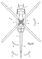
- Rotorcraft 10 has a main rotor 12 with a plurality of main rotor blades 14. The pitch of main rotor blades 14 can be collectively and cyclically manipulated to selectively control direction, thrust and lift of rotorcraft 10.
- Rotorcraft 10 has a landing gear system 16 to provide ground support for rotorcraft 10.
- Rotorcraft 10 includes a left side 18 and a right side 20.
- Rotorcraft 10 includes a fuselage 22, and a tailboom 24 extending from the rear of fuselage 22.
- Main rotor 12 rotates in a direction indicated by an arrow 26. Such rotation produces a torque on fuselage 22 in a direction indicated by an arrow 28.
- a “right” thrust refers to a thrust in the starboard direction of an aircraft.
- a “left” thrust refers to a thrust in the port direction of an aircraft.
- Aft portion 30 of tailboom 24 includes a variable thrust cross-flow fan system 32 that is operable to produce variable thrust in both a pro-torque direction 34 and an anti-torque direction 36.
- Variable thrust cross-flow fan system 32 is mounted along the longitudinal axis of tailboom 24.
- variable thrust cross-flow fan system 32 may provide a multi-directional, including bi-directional, and variable intensity thrust to provide anti-torque and yaw control for rotorcraft 10.
- Variable thrust cross-flow fan system 32 is rotatable around a central longitudinal axis by a drive system 38.
- drive system 38 includes an engine and transmission 40 and a drive shaft 42.
- Engine and transmission 40 provide torque and rotational energy to a drive shaft 44 that rotates main rotor 12.
- engine and transmission 40 provide torque and rotational energy to drive shaft 42.
- Drive shaft 42 may be a single long shaft or a series of shorter shafts and may preferably having flexible couplings to allow flexure.
- Drive shaft 42 mechanically couples to variable thrust cross-flow fan system 32. It should be noted that since engine 40 preferably operates at a constant rotational speed or velocity during flight operations, the gearing in transmission 40 is used to adjust the engine output to an optimum rotational speed for variable thrust cross-flow fan system 32.
- variable thrust cross-flow fan system 32 has a plurality of blades 46 that are rotated responsive to the rotation of drive shaft 42.
- blades 46 of variable thrust cross-flow fan system 32 rotate at a constant speed proportional to that of main rotor 12 based upon the gear ratios of transmission 42. Rotating blades 46 of variable thrust cross-flow fan system 32 at a constant speed is advantageous, at this eliminates any additional systems and the associated complications necessary to enable variable speed rotation.
- Variable thrust cross-flow fan system 32 produces a variable and reversible thrust, including thrusts in the pro-torque and anti-torque directions 34, 36, by changing the pitch, or angles of attack, of blades 46 of variable thrust cross-flow fan system 32 responsive to commands from an actuator assembly 48.
- Actuator assembly 48 may receive input from a pilot via anti-torque pedals or other source to operate variable thrust cross-flow fan system 32 to control the yaw of rotorcraft 10, including compensating for the torque on fuselage 22 caused by main rotor 12.
- both the airflow and thrust produced by variable thrust cross-flow fan system 32 is substantially perpendicular to drive shaft 42, and therefore in a substantially lateral direction relative to rotorcraft 10.
- rotorcraft 10 is merely illustrative of a variety of aircraft that can implement the embodiments disclosed herein.
- Other aircraft implementations can include hybrid aircraft, tilt rotor aircraft, unmanned aircraft, gyrocopters and a variety of helicopter configurations, to name a few examples.
- the illustrative embodiments may also be used on airplanes. It should be appreciated that even though aircraft are particularly well suited to implement the embodiments of the present disclosure, non-aircraft vehicles and devices can also implement the embodiments.
- variable thrust cross-flow fan system 100 includes a cross-flow fan assembly 102.
- Cross-flow fan assembly 102 includes a forward driver plate 104 and an aft driver plate 106, which are coupled to, and rotatable by, drive shaft 108.
- Cross-flow fan assembly 102 also includes blades 110a-110g. Each blade 110a-110g has a respective forward end 112a-112g and a respective aft end 114a-114g.
- each of blades 110a-110g are rotatably coupled to an aft side of forward driver plate 104.
- the aft ends 114a-114g of blades 110a-110g are rotatably coupled to a forward side 116 of aft driver plate 106.
- blades 110a-110g may rotate or pivot while rotating around drive shaft 108.
- cross-flow fan assembly 102, along with blades 110a-110g rotate in a direction indicated by an arrow 117.
- the term "coupled” may include direct or indirect coupling by any means, including moving and non-moving mechanical connections.
- Forward driver plate 104 forms linkage holes 118a-118g.
- Driver plate 106 also forms corresponding linkage holes that are not visible in the illustrated embodiments.
- forward end 112a of blade 110a includes a forward driver pin 122 and aft end 114a of blade 110a include an aft driver pin 124.
- Blades 110b-110g include similar forward and aft driver pins.
- Each of the forward driver pins is insertable and rotatable within a respective linkage hole 118a-118g of forward drive plate 104.
- each of the aft driver pins is insertable and rotatable within a respective linkage hole formed by aft driver plate 106.
- driver pins 122, 124 are integral with or coupled to respective end caps 126, 128, as best seen in figure 5 .
- driver pins 122, 124 may be the opposite ends of a shaft (not shown) that extends longitudinally through the body of blade 110a.
- Variable thrust cross-flow fan system 100 includes a control cam 130, which is movable relative to cross-flow fan assembly 102, and in particular to forward driver plate 104, along axis 132.
- control cam 130 rotates at substantially the same speed and direction 117 as cross-flow fan assembly 102.
- Control cam 130 is coupled to blades 110a-110g.
- control cam 130 is coupled to blades 110a-110g by linkages 134a-134g.
- linkage 134a has an inner end 136 and an outer end 138. Outer end 138 of linkage 134a is fixedly coupled to forward driver pin 122 of blade 110a, and therefore blade 110a does not rotate relative to linkage 134a.
- each of linkages 134a-134g is fixedly coupled to a respective one of blades 110a-110g, as illustrated.
- Inner end 136 of linkage 134a is slidably coupled to control cam 130 at follower slot 140a of control cam 130.
- inner ends of linkages 134b-134g are coupled to control cam 130 at follower slots 140b-140g of control cam 130.
- follower slots 140a-140g allow the inner ends of linkages 134a-134g to move concentrically relative to control cam 130, while constraining the inner ends of linkages 134a-134g from moving in the radial direction.
- inner end 136 of linkage 134a includes a follower pin 142a that is at least partially inserted, and slidably engaged, with follower slot 140a.
- follower pin 142a may slide along all or a portion of the length of follower slot 140a.
- follower pin 142a may extend between two portions of linkage 134a that are on opposite sides of control cam 130.
- follower pins 142a-142g on the inner end of each of linkages 134a-134g are slidably engaged with their respective follower slots 140a-140g in the same or similar manner as that described for linkage 134a.
- control cam 130 is generally circular having a center point 144 and radius 146.
- Each of follower slots 140a-140g form at least a portion of a circle, or circular arc, and has center point 144 and radius 148.
- radius 146 of control cam 130 is larger than radius 148 of follower slots 140a-140g.
- control cam 130, linkages 134a-134g and follower pins 142a-142g may be considered a control assembly coupled to blades 110a-110g.
- blade 110a has leading edge 150 and chord line 152.
- Chord line 152 extends from leading edge 150 to trailing edge 154 of blade 110a.
- Chord line 152 has a length L.
- forward driver pin 122 may be located a distance of approximately L/4, or quarter chord, from leading edge 150.
- blade 110a may be rotatable around a point that is L/4 from leading edge 150, whether or not forward driver pin 122 is utilized.
- forward driver pin 122, or a point of rotation for blade 110a may be located anywhere along chord line 152.
- Each of blades 110a-110g may have the same or similar placement of a point of rotation or a forward driver pin as that described with respect to blade 110a in figure 4A .
- blades 110a-110g form an acute angle with the respective linkages 134a-134g to which they are coupled.
- linkage 134a has a centerline 156.
- Angle 158 formed between chord line 152 of blade 110a and centerline 156 of linkage 134a is an acute angle.
- angle 158 may be another type of angle, such as an obtuse angle.
- Control cam 130 is shown in the illustrated embodiments to be circular, however, a control cam of the present disclosure may be any shape that enables some or all of the control cam functionality described in the illustrative embodiments.
- control cam 130 may have an irregular shape, while still forming follower slots 140a-140g.
- Cross-flow fan assembly 102 may have any length depending on the application. Varying the length of blades 110a-110g may help to accommodate the centrifugal load on each of blades 110a-110g. By way of non-limiting example, blades 110a-110g may be on the order of one or more inches or one or more feet.
- cross-flow fan assembly 102 may have any number of blades depending on the particular application both less than or greater than seven. The number of linkages, follower slots, follower pins and other parts accompanying each blade may also vary as the number of blades changes.
- Blades 110a-110g preferably have a shape suitable for providing thrust in accordance with the illustrative embodiments.
- blades 110a-110g may have an airfoil shape, arc shape or teardrop shape.
- Blades 110a-110g may also be either symmetric or non-symmetric along each blade's chord line.
- Blades 110a-110g may have any thickness or stiffness suitable to withstand the centrifugal load of the particular application and may be formed from any suitable material, including metals such as aluminum and composites such as carbon epoxy.
- Blades 110a-110g may be hollow or solid and may be formed using any suitable method of manufacture.
- blades 110a-110g may move into one of an infinite number of pitch angle configurations in response to movement of control cam 130 along axis 132.
- Control cam 130 is movable relative to forward driver plate 104, and in particular, control cam 130 is movable, or translatable, into an infinite number of positions along a plane substantially parallel to forward driver plate 104.
- control cam 130 rotates blades 110a-110g via linkages 134a-134g.
- each of blades 110a-110g may have a different pitch angle
- the positions of all of blades 110a-110g are referred to, in the collective sense, as pitch angle configurations.
- the control assembly is operable to change the pitch angle configuration of blades 110a-110g to selectively generate thrust in a plurality of directions including a first direction and a second, opposite direction.
- blades 110a-110g rotate in a counterclockwise manner, indicated by arrow 117, along a circular path of travel 160.
- each blade 110a-110g may have a positive, negative or zero pitch angle at any particular point around circular path of travel 160 during each revolution.
- Blade 110a is shown to have substantially zero pitch in figure 4A , a positive pitch angle in figure 4B and a negative pitch angle in figure 4C .
- circular path of travel 160 is the path along which forward driver pin 122 travels.
- a tangential projection 162 is also shown for blade 110a.
- tangential projection 162 is tangential to the circular path of travel 160 at a point at which circular path of travel 160 and forward driver pin 122 intersect. Tangential projection 162 may also be a line tangential to the circular path of travel of a point of rotation for blade 110a. In figure 4A , blade 110a may be considered to have substantially zero, or extremely low, pitch because the angle between tangential projection 162 and chord line 152 of blade 110a is substantially, or very close to, zero.
- blade 110a is shown to have a positive pitch angle.
- Blade 110a has a positive pitch angle because trailing edge 154 is biased away from center point 165 of circular path of travel 160 and angle 164 formed between chord line 152 and tangential projection 162 is non-zero.
- blade 110a has a negative pitch angle because trailing edge 154 of blade 110a is biased towards center point 165 of circular path of travel 160 and angle 164 formed between chord line 152 and tangential projection 162 is non-zero.
- control cam 130 is substantially concentric with drive shaft 108, forward driver plate 104 and circular path of travel 160.
- blades 110a-110g are in a neutral configuration and each of blades 110a-110g have a substantially zero pitch during each rotation around circular path of travel 160, as illustrated in figure 4A .
- blades 110a-110g are in the neutral configuration, all of blades 110a-110g have a zero angle of attack, and therefore produce no thrust in either direction.
- blades 110a-110g are in a right thrust configuration as a result of control cam 130 moving to a left position relative to the rotorcraft.
- the pitch angles of each of blades 110a-110g fluctuate between positive and negative pitch angles during each revolution around circular path of travel 160 such that a right thrust is produced thereby.
- control cam 130 is in a position that causes blades 110a-110g to be in the right thrust position, blades 110a-110g rotate eccentrically in relation to control cam 130.
- Control cam 130 is also eccentric to the axis of rotation of both drive shaft 108 and cross-flow fan assembly 102 while in the right thrust position.
- control cam 130 moves in the opposite direction as the thrust produced when blades 110a-110g rotate along circular path of travel 160.
- Blades 110a, 110b, 110g are located on a left portion of circular path of travel 160 and each have varying positive pitch angles depending on their respective locations in the rotation cycle.
- Blade 110a which is substantially leftmost in circular path of travel 160, has the largest positive pitch angle of all blades 110a-110g.
- Each blade 110a-110g progressively moves into or out of this most positive pitch angle of blade 110a as each blade 110a-110g moves into or out of the substantially leftmost position at which blade 110a is shown.
- Blades 110c, 110d, 110e, 110f are each on a right portion of circular path of travel 160 for blades 110a-110g. Blades 110c, 110d, 110e, 110f that are on the right portion of the circular path of travel 160 each have varying negative pitch angles. Each blade 110a-110g has its largest negative pitch angle when it reaches the rightmost point of circular path of travel 160. The pitch angles of blades 110a-110g are substantially zero at the topmost and bottommost points of circular path of travel 160, thereby causing substantially zero thrust in the vertical directions. Each of blades 110a-110g have substantially zero pitch angles twice during each revolution along circular path of travel 160, namely, at the topmost and bottommost points of circular path of travel 160.
- the right thrust configuration of blades 110a-110g shown in figure 3B produces a rightward thrust for the rotorcraft as the blades 110a-110g rotate in the direction indicated by arrow 117.
- the right thrust may be either a pro-torque thrust or an anti-torque thrust, depending on the rotational direction of the rotors of the rotorcraft.
- the right thrust configuration shown in figure 3B may be either a pro-torque thrust configuration or an anti-torque thrust configuration.
- control cam 130 has moved rightward, relative to the rotorcraft, from the neutral position of figure 3A to cause blades 110a-110g to move into a left thrust configuration.
- blades 110a-110g rotate, along arrow 117, to produce a left thrust for the rotorcraft.
- the left thrust may be either a pro-torque thrust or an anti-torque thrust, depending on the rotational direction of the rotors of the rotorcraft.
- the left thrust configuration shown in figure 3C may be either a pro-torque thrust configuration or an anti-torque thrust configuration.
- blades 110a-110g change pitch angle during each revolution around circular path of travel 160.
- each of blades 110a-110g fluctuates between a positive and negative pitch angle during each revolution around circular path of travel 160.
- Control cam 130 has moved in an opposite direction from the leftward thrust produced by blades 110a-110g in the left thrust configuration. Also, the distance between the leftmost point of control cam 130 and the leftmost point of forward driver plate 104 is greater than the distance between the rightmost point of control cam 130 and the rightmost point of forward driver plate 104.
- the circular path of travel 160 in the left thrust configuration is eccentric to control cam 130. In the left thrust configuration, control cam 130 is also eccentric to the axis of rotation of drive shaft 108 and cross-flow fan assembly 102. In the left thrust configuration, blades 110c, 110d, 110e, located on the right portion of circular path of travel 160, each have positive pitch angles that are different from one another.
- Blades 110a, 110b, 110f, 110g located on the left portion of circular path of travel 160, each have varying negative pitch angles. Blades 110a-110g, when at the topmost or bottommost point of each revolution, have a substantially zero pitch angle, thereby producing substantially zero vertical thrust in the illustrated embodiment. Each of blades 110a-110g have substantially zero pitch angles twice during each revolution along circular path of travel 160, namely, at the topmost and bottommost points of circular path of travel 160,
- each blade 110a-110g may produce a lift, or thrust, force approximately along a radial line between each blade's quarter chord point and center point 165 of circular path of travel 160.
- the thrust force generated by each blade 110a-110g may be proportional to the angle of attack, or pitch, of the individual blade.
- a pilot of the rotorcraft may vary the thrust of variable thrust cross-flow fan system 100 by changing the lateral position of control cam 130.
- the right and left thrusts described herein, opposite in direction, are produced by a single cross-flow fan assembly 102 that rotates at a substantially constant speed that is substantially equal to the rotational speed of drive shaft 108.
- control cam 130 may be in an infinite number of positions along the axis 132 to produce an infinite number of potential thrust intensities in either the right or left direction.
- a pilot of the rotorcraft by controlling the position of control cam 130, may manage the yaw and torque forces experienced by the rotorcraft during flight.
- variable thrust cross-flow fan system 200 includes a plurality of blades 210a-210h that are shown in a variety of pitch angle configurations, which change in response to an input received from a pilot of the rotorcraft.
- Figures 6A-6E show a tailboom housing 274 having an upper potion 274a and lower portion 274b. The illustrated cross sections are viewed from a location aft of the rotorcraft such that tailboom housing 274 has a left portion 270 and a right portion 272.
- blades 210a-210h form obtuse angles with the respective linkages to which they are attached. As discussed above, blades 210a-210h may form either obtuse or acute angles with their respective linkages. Also, in the illustrated embodiment, blades 210a-210h rotate in a counterclockwise direction at a substantially constant speed during rotorcraft flight.
- blades 210a-210h are in a neutral pitch angle configuration as the control cam (not shown) is substantially concentric with circular path of travel 260 of blades 210a-210h.
- Input may be received from a pilot of the rotorcraft that causes the control cam to be shifted from the neutral position.
- the input may be one or more anti-torque pedals in the cockpit of the rotorcraft.
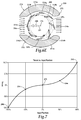
- the anti-torque pedals may allow for varying degrees of input intensity, expressed as a continuum on the x-axis of figure 7 .
- the anti-torque pedals may allow for input ranging from -100% to 100%, and all points therebetween.
- variable thrust cross-flow fan system 200 may have a direction and intensity that is determined by the input position originating from the cockpit of the rotorcraft or elsewhere.
- blades 210a-210h have a neutral pitch angle configuration
- substantially zero thrust is produced.
- a neutral position center point 279 which is the center point of the control cam when the control cam is in the neutral configuration
- the input position originating from an input control of the rotorcraft may be at 0%, as indicated by point 278 in figure 7 .
- a maximum right thrust 280 is produced by blades 210a-210h in the depicted pitch angle configuration. In this right thrust configuration, maximum right thrust 280 is at 100% of variable thrust cross-flow fan system's thrust range (-100% to 100%), as indicated by point 282 in figure 7 .
- Maximum right thrust 280 corresponds with an input position of 100% from one of the exemplary input controls described above.
- control cam In the maximum right thrust configuration of figure 6A , the control cam has moved rightward of neutral position 276 of the control cam to a maximum allowable extent. The distance that the control cam has moved is schematically illustrated by showing neutral position center point 279 relative to center point 281 of the control cam. It is also noted that the control cam has moved in the same direction as the thrust produced by blades 210a-210h. This is in contrast to the illustrative embodiments shown in figures 2, 3A-3C, 4A-4C and 5 , in which the control cam moved in an opposite direction as the thrust produced by the blades of the variable thrust cross-flow fan system 100.
- the direction that the control cam moves relative to the thrust direction may be caused by whether the angle between each blade and its respective linkage is acute or obtuse.
- blades 210a-210h remain in a right thrust pitch angle configuration.
- the control cam is closer to neutral position 276 than it was in figure 6A , thereby causing an intermediate right thrust 284, which is less than maximum right thrust 280 in figure 6A .
- the reduced thrust is generated as the maximum pitch angles of blades 210a-210h is reduced and the air flow through variable thrust cross-flow fan system 200 is reduced as indicated by the reduced density airflow arrows 204.
- the distance that the control cam has moved is schematically illustrated by showing neutral position center point 279 relative to center point 281 of the control cam.
- intermediate right thrust 284 is approximately 20% of maximum right thrust 280, as indicated by point 286.
- an input position of 50% produces the intermediate right thrust 284 of approximately 20% of maximum right thrust 280.
- blades 210a-210h transition between positive pitch, zero pitch, negative pitch, zero pitch and back to positive pitch during each revolution of the cross-flow fan assembly.
- blades 210a-210h approach the leftmost point of circular path of travel 260, the blades have progressively greater positive pitch reaching a maximum positive pitch at the leftmost point of circular path of travel 260.
- blades 210a-210h retreat from the leftmost point of circular path of travel 260, the blades have progressively lesser positive pitch reaching zero pitch proximate bottommost point of circular path of travel 260.
- blades 210a-210h As blades 210a-210h approach the rightmost point of circular path of travel 260, the blades have progressively greater negative pitch reaching a maximum negative pitch at the rightmost point of circular path of travel 260. Thereafter, as blades 210a-210h retreat from the rightmost point of circular path of travel 260, the blades have progressively lesser negative pitch, reaching zero pitch proximate topmost point of circular path of travel 260. Each blade 210a-210h repeats this cycle on each revolution of the cross-flow fan assembly.
- a maximum left thrust 288 is produced by blades 210a-210h in the depicted pitch angle configuration which corresponds to point 290 in figure 7 and the -100% location on the continuum of -100% to 100%.
- the control cam has been moved a maximum allowable distance to the left of neutral position 276.
- the distance that the control cam has moved is schematically illustrated by showing neutral position center point 279 relative to center point 281 of the control cam.
- a leftward move of the control cam corresponds to a leftward thrust.
- the left thrust that is produced by blades 210a-210h is the opposite of the airflow direction through blades 210a-210h, as indicated by high-density airflow arrows 206.
- maximum left thrust 288 corresponds with an input position of -100% from one of the exemplary input controls described above.
- blades 210a-210h produce an intermediate left thrust 292 in the depicted pitch angle configuration.
- Intermediate left thrust 292 is less than maximum left thrust 288.
- intermediate left thrust 292 is approximately 20% of maximum left thrust 288, as indicated by point 294 in figure 7 .
- the control cam is closer to neutral position 276 than in the maximum left thrust configuration of figure 6E .
- the distance that the control cam has moved is schematically illustrated by showing neutral position center point 279 relative to center point 281 of the control cam.
- the input position has been set at -50% from one of the exemplary input controls described above, as shown in figure 7 .
- the reduced thrust is generated as the maximum pitch angles of blades 210a-210h is reduced and the air flow through variable thrust cross-flow fan system 200 is reduced as indicated by the reduced density airflow arrows 208.
- blades 210a-210h transition between positive pitch, zero pitch, negative pitch, zero pitch and back to positive pitch during each revolution of the cross-flow fan assembly.
- blades 210a-210h approach the rightmost point of circular path of travel 260, the blades have progressively greater positive pitch reaching a maximum positive pitch at the rightmost point of circular path of travel 260.
- blades 210a-210h retreat from the rightmost point of circular path of travel 260, the blades have progressively lesser positive pitch reaching zero pitch proximate topmost point of circular path of travel 260.
- blades 210a-210h As blades 210a-210h approach the leftmost point of circular path of travel 260, the blades have progressively greater negative pitch reaching a maximum negative pitch at the leftmost point of circular path of travel 260. Thereafter, as blades 210a-210h retreat from the leftmost point of circular path of travel 260, the blades have progressively lesser negative pitch, reaching zero pitch proximate bottommost point of circular path of travel 260. Each blade 210a-210h repeats this cycle on each revolution of the cross-flow fan assembly.
- FIGS 6A-6E illustrate that the variability of the thrust based upon the pitch angle configuration of blades 210a-210h which varies responsive to control cam movement.
- the thrust generated by variable thrust cross-flow fan system 200 is variable in both intensity and direction, either a leftward or rightward direction, and is therefore reversible.
- five pitch angle configurations of blades 210a-210h have been shown in figures 6A-6E , it should be understood by those skilled in the art that blades 210a-210h may have an infinite number of pitch angle configurations producing an infinite number of thrust intensities, by moving the control cam along an infinite number of possible points along an axis lateral to the direction of travel of the rotorcraft.
- the thrust intensity and direction may vary according to the illustrated curve, including any point thereon.
- a pilot may vary the input position of an input control to vary the thrust intensity and direction produced by variable thrust cross-flow fan system 200 to manage the yaw and anti-torque of the rotorcraft.
- the input versus torque curve for a particular implementation will vary based upon factors including the size, shape and materials used to form the blades, the number of blades, the rotational speed of the cross-flow fan system and other parameters.
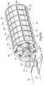
- variable thrust cross-flow fan system 300 includes a plurality of blades, only blades 310a-310d being visible, wherein each of the blades is divided into seven blade segments.
- the blade segments of each blade 310a-310d are separated by divider plates 396a-396f, which are disposed at regular intervals between forward driver plate 304 and aft driver plate 306.
- divider plates 396a-396f are substantially parallel to both forward driver plate 304 and aft driver plate 306.
- divider plates 396a-396f may be substantially the same shape as forward driver plate 304 and aft driver plate 306.
- Each divider plate 396a-396f divides adjacent segments of each blade 310a-310d. For example, divider plate 396a divides blade segments 326, 328 of blade 310c. By dividing blades 310a-310d into smaller blade segments, divider plates 396a-396f may increase the tolerance of blades 310a-310d to centrifugal forces resulting from the rotation of cross-flow fan assembly 302.
- Figures 8A-8C also show an actuator mechanism 304 by which control cam 330 may be moved in order to change the pitch configurations of blades 310a-310d.
- variable thrust cross-flow fan system 300 includes an input receiving post 336 that is adjacent to control cam 330 and rotatable about a vertical axis.
- a bypass plate 338 is coupled to control cam 330.
- Bypass plate 338 includes an aperture 340.
- Drive shaft 308 passes through aperture 340 of bypass plate 338 and is foreshorten in the illustrated embodiment for clarity of presentation.
- Aperture 340 provides lateral clearance for drive shaft 308 such that when bypass plate 338 moves along a lateral plane parallel to forward drive plate 304, bypass plate 338 and drive shaft 308 are substantially non-touching. Such clearance prevents bypass plate 338 from interfering with the rotation of drive shaft 308.
- a bell crank 342 includes a first end 344 and a second end 346. First end 344 of bell crank 342 is coupled to input receiving post 336. Second end 346 of bell crank 342 is coupled to an extender link 348, which is coupled to bypass plate 338. Wires 350, 352 are coupled to input receiving post 336. The position of wires 350, 352 may respond to an input position, such as the input positions shown in figure 7 . Wires 350, 352 may be moved by the pilot of the rotorcraft, which in turn rotates input receiving post 336 and thereby moves bypass plate 338 and control cam 330 into one of several positions along a plane substantially parallel to forward driver plate 304. Movement of control cam 330, as described above, causes blades 310a-310d to move into a particular pitch angle configuration. Therefore, moving wires 350, 352, via input from an input control, changes the thrust intensity and direction produced by blades 310a-310d.
- blades 310a-310d are in a neutral configuration, thereby creating substantially zero thrust while in constant speed rotation.
- wires 350, 352 have been operated to rotate input receiving post 336 and cause blades 310a-310d to move into a right thrust configuration.
- wires 350, 352 have been operated to rotate input receiving post 336 to cause blades 310a-310d to move into a left thrust configuration.
- wires 350, 352 may be attached to anti-torque pedals located in a cockpit of the rotorcraft.
- the anti-torque pedals may allow for input positions along a continuum of -100% to 100% as shown in figure 7 , depending on how far each anti-torque pedal is depressed.
- actuation mechanism 304 for operating control cam 330 and thus the intensity and direction of thrust generated by variable thrust cross-flow fan system 300 has been described and depicted, it should be understood by those skilled in the art that other actuation mechanisms could be used to operate a control cam and variable thrust cross-flow fan system of the present disclosure.
- an actuation mechanism of the present disclosure could alternatively be a hydraulic actuation mechanism, an electrically actuation mechanism in a fly-by-wire environment, or other suitable actuation mechanism operable to allow for input anywhere along the spectrum shown on the x-axis of figure 7 .
- housing 400 provides an enclosure for the moving parts of a variable thrust cross-flow fan system and forces air flow to follow a predetermined path.
- Housing 400 may be mounted in or be formed integrally with a tailboom of a rotorcraft.
- housing 400 includes a left duct 402, which may open onto the left side of the tailboom.
- Housing 400 also includes a right duct 404, which may open up to the right side of the tailboom. Left duct and right duct 402, 404 allow air to pass through the housing 400 so that thrust may be generated in accordance with the illustrative embodiments described above.
- Each duct 402, 404 includes a plurality of horizontal slats 406 to provide for directional control of the airflow and thrust of variable thrust cross-flow fan system.
- Slats 406 may be adjustable or movable based on input from a pilot to enable thrust vectoring operations.
- slats 406 may be tilted such that a left thrust generated by the variable thrust cross-flow fan system has an upward or downward component, thereby providing pitch, in addition to yaw, control of the rotorcraft.
- duct 402, 404 could include vertical slats for additional directional control of the airflow and thrust of variable thrust cross-flow fan system.
- housing 400 is shown to have oppositely disposed ducts on its left and right side, a housing of the present disclosure may have ducts in other locations and other orientations, including top ducts, bottom ducts, or any combination of two or more ducts disposed about a variable thrust cross-flow fan system of the present disclosure.
- the control cam may be allowed to travel in directions other than the lateral horizontal axis of the rotorcraft to enable variable thrust.
- control cam may be allowed to travel diagonally or vertically in order to create the desired thrust direction and intensity the variable thrust cross-flow fan system.
- a pilot may control both the yaw and pitch of the rotorcraft.
- Housing 400 may be used to achieve a pressure differential that allows for more efficient thrust. In some examples, an 80-100% improvement in thrust may be achievable using such a pressure differential. Housing 400 also provides protection for the blades of the variable thrust cross-flow fan system, such as by preventing objects from hitting the blades. Housing 400 also prevents injury by creating a barrier between people and the blades.
- variable thrust cross-flow fan system 500 includes a plurality of blades 510a-510h that are rotatably coupled to driver plates 504, 506. Blades 510a-510h are fixably coupled to respective linkages 534a-534h via driver pins 522a-522h.
- control cam 530 is non-rotating relative to cross-flow fan assembly 502 and drive shaft 508. Instead, control cam 530 includes one continuous follower slot 540 along which follower pins 542a-542h may move.
- control cam 530 linkages 534a-534h, driver pins 522a-522h and follower pins 542a-542h may be considered a control assembly coupled to blades 510a-510h.
- movement of control cam 530 moves blades 510a-510h into different pitch angle configurations to provide variable thrust as well as reversible thrust in two or more directions.
- the illustrative embodiments are described as providing thrust for a rotorcraft, or indeed for any object on which the variable thrust cross-flow fan system is mounted, the illustrative embodiments may also be used as a turbine in, for example, a generator. In these alternative embodiments, the pitch angle configuration of the blades may be changed in order to most effectively receive or harness a fluid, such as air or water, to turn the cross-flow fan assembly in a manner that produces energy.
- a fluid such as air or water
Landscapes
- Engineering & Computer Science (AREA)
- Mechanical Engineering (AREA)
- Aviation & Aerospace Engineering (AREA)
- General Engineering & Computer Science (AREA)
- Structures Of Non-Positive Displacement Pumps (AREA)
Abstract
Description
- The present disclosure relates, in general, to cross-flow fan systems for use on rotorcraft and, in particular, to cross-flow fan systems operable to be mountable in a tailboom of a rotorcraft and operable to provide variable thrust for anti-torque and yaw control of the rotorcraft.
- The main rotor of a helicopter, which produces lift necessary for flight, also produces a counteracting torque force on the fuselage of the helicopter. The helicopter's tail rotor, located to the rear of the main rotor, is used to counteract this torque and to control the yaw of the helicopter. Tail rotors are typically mounted on a horizontal axis perpendicular to the direction of flight of the rotorcraft. The blades of a tail rotor typically change pitch to control thrust direction and intensity.
- Traditional tail rotors have several drawbacks. First, because the tail rotor blades are large and openly exposed, they are susceptible to striking people or other objects while in operation. Second, the noise produced by traditional tail rotors can be unacceptably high, creating flyover acoustic problems. Such noise may be undesirable in a low noise environment or during clandestine activities. Traditional tail rotors may also create undesirable profile drag during flight, and/or cause thrust reduction during sideward flight.
- Attempts have been made to use cross-flow fans to control helicopter yaw. It has been found, however, that cross-flow fans systems require redundancy of parts and detrimentally complex gearing and clutching schemes to provide thrust in more than a single direction. For example, rotorcrafts that employ cross-flow fans with unidirectional thrust functionality may require two or more cross-flow fans pointed in opposite directions to achieve thrust in both the pro-torque and anti-torque directions. Accordingly, the need has arisen for improved anti-torque systems for use on rotorcraft that have a reduced noise signature, a reduced impact risk and a reduced profile drag while also providing thrust in more than one direction.
- In a first aspect, the present disclosure is directed to a variable thrust cross-flow fan system for a rotorcraft. The system includes a cross-flow fan assembly having a longitudinal axis and including first and second driver plates having a plurality of blades rotatably mounted therebetween. The plurality of blades are disposed radially outwardly from the longitudinal axis such that the plurality of blades have a generally circular path of travel when the cross-flow fan assembly rotates about the longitudinal axis. The plurality of blades are moveable between a plurality of pitch angle configurations. A control assembly is coupled to the plurality of blades. The control assembly is operable to change the pitch angle configuration of the plurality of blades to generate variable thrust at a substantially constant rotational speed of the cross-flow fan assembly.
- In certain embodiments, the control assembly may include a control cam that is operable to translate relative to the cross-flow fan assembly to change the pitch angle configuration of the plurality of blades. In some embodiments, the control cam is operable to rotate relative to the cross-flow fan assembly. In other embodiments, the control cam is substantially non-rotatable relative to the cross-flow fan assembly. In certain embodiments, the control assembly includes a control cam and a plurality of linkages. In such embodiments, the control cam may be coupled to the plurality of blades by the plurality of linkages, wherein each of the plurality of linkages has an inner end and an outer end with the inner end of each of the plurality of linkages slidably coupled to the control cam and the outer end of each of the plurality of linkages fixedly coupled to one of the plurality of blades. In some embodiments, the control cam forms at least one follower slot such that a follower pin on the inner end of each of the plurality of linkages may slidably engaged with the at least one follower slot. In other embodiments, the control cam forms a plurality of follower slots such that a follower pin on the inner end of each of the plurality of linkages may slidably engaged with one of the plurality of follower slots.
- In some embodiments, the plurality of pitch angle configurations may include at least one right thrust configuration, a neutral configuration and at least one left thrust configuration. In certain embodiments, the plurality of pitch angle configurations may include a plurality of anti-torque thrust configurations and/or a plurality of pro-torque thrust configurations. In some embodiments, the plurality of pitch angle configurations may include pitch angle configurations wherein each of the plurality of blades changes pitch angle during each revolution around the generally circular path of travel, wherein each of the plurality of blades fluctuates between a positive pitch angle and a negative pitch angle during each revolution around the generally circular path of travel and wherein one or more blades of the plurality of blades has the negative pitch angle while one or more blades of the plurality of blades has the positive pitch angle.
- In some embodiments, the variable thrust is a reversible thrust. In certain embodiments, the control assembly is operable to change the pitch angle configuration of the plurality of blades to selectively generate thrust in a plurality of directions including a first direction and a second direction. In such embodiments, the first direction may be substantially opposite from the second direction.
- In some embodiments, the variable thrust cross-flow fan system may include an actuator assembly that is operably coupled to the control assembly and operable to translate the control assembly relative to the cross-flow fan assembly to change the pitch angle configuration of the plurality of blades.
- In a second aspect, the present disclosure is directed to a rotorcraft including a fuselage, a tailboom extending from the fuselage, a drive system having an engine, transmission and a drive shaft extending at least partially within the tailboom and a variable thrust cross-flow fan system located at an aft portion of the tailboom. The variable thrust cross-flow fan system includes a cross-flow fan assembly mechanically coupled to the drive shaft and operable to rotate with the drive shaft about a longitudinal axis. The cross-flow fan assembly includes first and second driver plates having a plurality of blades rotatably mounted therebetween. The plurality of blades are disposed radially outwardly from the longitudinal axis such that the plurality of blades have a generally circular path of travel when the cross-flow fan assembly rotates about the longitudinal axis. The plurality of blades are moveable between a plurality of pitch angle configurations. A control assembly is coupled to the plurality of blades. The control assembly is operable to change the pitch angle configuration of the plurality of blades to generate variable thrust at a substantially constant rotational speed of the cross-flow fan assembly.
- In some embodiments, the variable thrust cross-flow fan system provides anti-torque thrust for the rotorcraft. In certain embodiments, the variable thrust cross-flow fan system provides yaw control thrust for the rotorcraft. In various embodiments, the plurality of pitch angle configurations includes a plurality of anti-torque thrust configurations, a neutral configuration and a plurality of pro-torque thrust configurations.
- For a more complete understanding of the features and advantages of the present disclosure, reference is now made to the detailed description along with the accompanying schematic figures in which corresponding numerals in the different figures refer to corresponding parts and in which:
-
Figures 1A-1C are schematic illustrations of an exemplary rotorcraft operating a variable thrust cross-flow fan system in accordance with embodiments of the present disclosure; -
Figure 2 is an isometric view of a variable thrust cross-flow fan system in accordance with embodiments of the present disclosure; -
Figures 3A-3C are side views of a variable thrust cross-flow fan system in accordance with embodiments of the present disclosure; -
Figures 4A-4C are side views of a blade of a variable thrust cross-flow fan system having various pitch angles in accordance with embodiments of the present disclosure; -
Figure 5 is a top view of a blade of a variable thrust cross-flow fan system in accordance with embodiments of the present disclosure; -
Figures 6A-6E are schematic illustrations of the blades of a variable thrust cross-flow fan system producing variable thrust in accordance with embodiments of the present disclosure; -
Figure 7 is a chart illustrating position versus thrust for a variable thrust cross-flow fan system in accordance with embodiments of the present disclosure; -
Figures 8A-8C are various isometric views a variable thrust cross-flow fan system and actuation assembly in accordance with embodiments of the present disclosure; -
Figure 9 is an isometric view of a housing for a variable thrust cross-flow fan system in accordance with embodiments of the present disclosure; and -
Figure 10 is an isometric view of a variable thrust cross-flow fan system in accordance with embodiments of the present disclosure. - While the making and using of various embodiments of the present disclosure are discussed in detail below, it should be appreciated that the present disclosure provides many applicable inventive concepts, which can be embodied in a wide variety of specific contexts. The specific embodiments discussed herein are merely illustrative and do not delimit the scope of the present disclosure. In the interest of clarity, all features of an actual implementation may not be described in this specification. It will of course be appreciated that in the development of any such actual embodiment, numerous implementation-specific decisions must be made to achieve the developer's specific goals, such as compliance with system-related and business-related constraints, which will vary from one implementation to another. Moreover, it will be appreciated that such a development effort might be complex and time-consuming but would nevertheless be a routine undertaking for those of ordinary skill in the art having the benefit of this disclosure.
- In the specification, reference may be made to the spatial relationships between various components and to the spatial orientation of various aspects of components as the devices are depicted in the attached drawings. However, as will be recognized by those skilled in the art after a complete reading of the present disclosure, the devices, members, apparatuses, and the like described herein may be positioned in any desired orientation. Thus, unless otherwise indicated, the use of terms such as "above," "below," "upper," "lower" or other like terms to describe a spatial relationship between various components or to describe the spatial orientation of aspects of such components should be understood to describe a relative relationship between the components or a spatial orientation of aspects of such components, respectively, as the devices described herein may be oriented in any desired direction.
- Referring to
Figures 1A-1C , arotorcraft 10 is schematically illustrated.Rotorcraft 10 has amain rotor 12 with a plurality ofmain rotor blades 14. The pitch ofmain rotor blades 14 can be collectively and cyclically manipulated to selectively control direction, thrust and lift ofrotorcraft 10.Rotorcraft 10 has alanding gear system 16 to provide ground support forrotorcraft 10.Rotorcraft 10 includes aleft side 18 and aright side 20.Rotorcraft 10 includes afuselage 22, and a tailboom 24 extending from the rear offuselage 22.Main rotor 12 rotates in a direction indicated by anarrow 26. Such rotation produces a torque onfuselage 22 in a direction indicated by anarrow 28. As used herein, including in the claims, the terms "left" and "right," unless otherwise indicated, refer to the port and starboard sides of an aircraft, respectively. For example, a "right" thrust refers to a thrust in the starboard direction of an aircraft. Conversely, a "left" thrust refers to a thrust in the port direction of an aircraft. -
Aft portion 30 oftailboom 24 includes a variable thrustcross-flow fan system 32 that is operable to produce variable thrust in both apro-torque direction 34 and ananti-torque direction 36. Variable thrustcross-flow fan system 32 is mounted along the longitudinal axis oftailboom 24. In some embodiments, variable thrustcross-flow fan system 32 may provide a multi-directional, including bi-directional, and variable intensity thrust to provide anti-torque and yaw control forrotorcraft 10. Variable thrustcross-flow fan system 32 is rotatable around a central longitudinal axis by adrive system 38. In the illustrated embodiment,drive system 38 includes an engine andtransmission 40 and adrive shaft 42. Engine andtransmission 40 provide torque and rotational energy to adrive shaft 44 that rotatesmain rotor 12. In addition, engine andtransmission 40 provide torque and rotational energy to driveshaft 42. Driveshaft 42 may be a single long shaft or a series of shorter shafts and may preferably having flexible couplings to allow flexure. Driveshaft 42 mechanically couples to variable thrustcross-flow fan system 32. It should be noted that sinceengine 40 preferably operates at a constant rotational speed or velocity during flight operations, the gearing intransmission 40 is used to adjust the engine output to an optimum rotational speed for variable thrustcross-flow fan system 32. - As discussed herein, variable thrust
cross-flow fan system 32 has a plurality ofblades 46 that are rotated responsive to the rotation ofdrive shaft 42. Preferably,blades 46 of variable thrustcross-flow fan system 32 rotate at a constant speed proportional to that ofmain rotor 12 based upon the gear ratios oftransmission 42. Rotatingblades 46 of variable thrustcross-flow fan system 32 at a constant speed is advantageous, at this eliminates any additional systems and the associated complications necessary to enable variable speed rotation. - Variable thrust
cross-flow fan system 32 produces a variable and reversible thrust, including thrusts in the pro-torque andanti-torque directions blades 46 of variable thrustcross-flow fan system 32 responsive to commands from anactuator assembly 48.Actuator assembly 48 may receive input from a pilot via anti-torque pedals or other source to operate variable thrustcross-flow fan system 32 to control the yaw ofrotorcraft 10, including compensating for the torque onfuselage 22 caused bymain rotor 12. In some embodiments, both the airflow and thrust produced by variable thrustcross-flow fan system 32 is substantially perpendicular to driveshaft 42, and therefore in a substantially lateral direction relative torotorcraft 10. - It should be appreciated that
rotorcraft 10 is merely illustrative of a variety of aircraft that can implement the embodiments disclosed herein. Other aircraft implementations can include hybrid aircraft, tilt rotor aircraft, unmanned aircraft, gyrocopters and a variety of helicopter configurations, to name a few examples. The illustrative embodiments may also be used on airplanes. It should be appreciated that even though aircraft are particularly well suited to implement the embodiments of the present disclosure, non-aircraft vehicles and devices can also implement the embodiments. - Referring to
figures 2, 3A-3C, 4A-4C and 5 , a variable thrust cross-flow fan system, including various configurations thereof, is schematically illustrated and generally designated 100. Variable thrustcross-flow fan system 100 includes across-flow fan assembly 102.Cross-flow fan assembly 102 includes aforward driver plate 104 and anaft driver plate 106, which are coupled to, and rotatable by,drive shaft 108.Cross-flow fan assembly 102 also includesblades 110a-110g. Eachblade 110a-110g has a respectiveforward end 112a-112g and a respectiveaft end 114a-114g. The forward ends 112a-112g of each ofblades 110a-110g are rotatably coupled to an aft side offorward driver plate 104. The aft ends 114a-114g ofblades 110a-110g are rotatably coupled to aforward side 116 ofaft driver plate 106. Thus, whendrive shaft 108 rotates forward andaft driver plates blades 110a-110g may rotate or pivot while rotating arounddrive shaft 108. In the illustrated embodiment,cross-flow fan assembly 102, along withblades 110a-110g, rotate in a direction indicated by anarrow 117. As used herein, the term "coupled" may include direct or indirect coupling by any means, including moving and non-moving mechanical connections. -
Forward driver plate 104forms linkage holes 118a-118g.Driver plate 106 also forms corresponding linkage holes that are not visible in the illustrated embodiments. As best seen infigure 5 ,forward end 112a ofblade 110a includes aforward driver pin 122 andaft end 114a ofblade 110a include anaft driver pin 124.Blades 110b-110g include similar forward and aft driver pins. Each of the forward driver pins is insertable and rotatable within arespective linkage hole 118a-118g offorward drive plate 104. Likewise, each of the aft driver pins is insertable and rotatable within a respective linkage hole formed byaft driver plate 106. In the illustrated embodiment, driver pins 122, 124 are integral with or coupled torespective end caps figure 5 . In another embodiment, driver pins 122, 124 may be the opposite ends of a shaft (not shown) that extends longitudinally through the body ofblade 110a. - Variable thrust
cross-flow fan system 100 includes acontrol cam 130, which is movable relative tocross-flow fan assembly 102, and in particular to forwarddriver plate 104, alongaxis 132. In the illustrated embodiment,control cam 130 rotates at substantially the same speed anddirection 117 ascross-flow fan assembly 102.Control cam 130 is coupled toblades 110a-110g. In particular,control cam 130 is coupled toblades 110a-110g bylinkages 134a-134g. With particular reference tolinkage 134a infigure 2 ,linkage 134a has aninner end 136 and anouter end 138.Outer end 138 oflinkage 134a is fixedly coupled toforward driver pin 122 ofblade 110a, and thereforeblade 110a does not rotate relative tolinkage 134a. Similarly, each oflinkages 134a-134g is fixedly coupled to a respective one ofblades 110a-110g, as illustrated. -
Inner end 136 oflinkage 134a is slidably coupled to controlcam 130 atfollower slot 140a ofcontrol cam 130. Similarly, inner ends oflinkages 134b-134g are coupled to controlcam 130 atfollower slots 140b-140g ofcontrol cam 130.Follower slots 140a-140g allow the inner ends oflinkages 134a-134g to move concentrically relative to controlcam 130, while constraining the inner ends oflinkages 134a-134g from moving in the radial direction. Referring again tolinkage 134a as representative of alllinkages 134a-134g,inner end 136 oflinkage 134a includes afollower pin 142a that is at least partially inserted, and slidably engaged, withfollower slot 140a. Indeed,follower pin 142a may slide along all or a portion of the length offollower slot 140a. In some embodiments,follower pin 142a may extend between two portions oflinkage 134a that are on opposite sides ofcontrol cam 130. Similarly,follower pins 142a-142g on the inner end of each oflinkages 134a-134g are slidably engaged with theirrespective follower slots 140a-140g in the same or similar manner as that described forlinkage 134a. With particular reference tofigure 3A ,control cam 130 is generally circular having acenter point 144 andradius 146. Each offollower slots 140a-140g form at least a portion of a circle, or circular arc, and hascenter point 144 andradius 148. In the illustrated embodiment,radius 146 ofcontrol cam 130 is larger thanradius 148 offollower slots 140a-140g. Together,control cam 130,linkages 134a-134g andfollower pins 142a-142g may be considered a control assembly coupled toblades 110a-110g. - With particular reference to
figure 4A ,blade 110a has leadingedge 150 andchord line 152.Chord line 152 extends from leadingedge 150 to trailingedge 154 ofblade 110a.Chord line 152 has a length L. In some embodiments,forward driver pin 122 may be located a distance of approximately L/4, or quarter chord, from leadingedge 150. In other embodiments,blade 110a may be rotatable around a point that is L/4 from leadingedge 150, whether or notforward driver pin 122 is utilized. In yet other embodiments,forward driver pin 122, or a point of rotation forblade 110a, may be located anywhere alongchord line 152. Each ofblades 110a-110g may have the same or similar placement of a point of rotation or a forward driver pin as that described with respect toblade 110a infigure 4A . - In the illustrated embodiment,
blades 110a-110g form an acute angle with therespective linkages 134a-134g to which they are coupled. With particular reference tofigure 4A ,linkage 134a has acenterline 156.Angle 158 formed betweenchord line 152 ofblade 110a andcenterline 156 oflinkage 134a is an acute angle. In other embodiments,angle 158 may be another type of angle, such as an obtuse angle.Control cam 130 is shown in the illustrated embodiments to be circular, however, a control cam of the present disclosure may be any shape that enables some or all of the control cam functionality described in the illustrative embodiments. For example,control cam 130 may have an irregular shape, while still formingfollower slots 140a-140g. -
Cross-flow fan assembly 102, and thereforeblades 110a-110g, may have any length depending on the application. Varying the length ofblades 110a-110g may help to accommodate the centrifugal load on each ofblades 110a-110g. By way of non-limiting example,blades 110a-110g may be on the order of one or more inches or one or more feet. In addition, while the illustrated embodiments showcross-flow fan assembly 102 to have sevenblades 110a-110g,cross-flow fan assembly 102 may have any number of blades depending on the particular application both less than or greater than seven. The number of linkages, follower slots, follower pins and other parts accompanying each blade may also vary as the number of blades changes.Blades 110a-110g preferably have a shape suitable for providing thrust in accordance with the illustrative embodiments. By way of non-limiting example,blades 110a-110g may have an airfoil shape, arc shape or teardrop shape.Blades 110a-110g may also be either symmetric or non-symmetric along each blade's chord line.Blades 110a-110g may have any thickness or stiffness suitable to withstand the centrifugal load of the particular application and may be formed from any suitable material, including metals such as aluminum and composites such as carbon epoxy.Blades 110a-110g may be hollow or solid and may be formed using any suitable method of manufacture. - To produce thrust,
blades 110a-110g may move into one of an infinite number of pitch angle configurations in response to movement ofcontrol cam 130 alongaxis 132.Control cam 130 is movable relative to forwarddriver plate 104, and in particular,control cam 130 is movable, or translatable, into an infinite number of positions along a plane substantially parallel toforward driver plate 104. By traveling alongaxis 132,control cam 130 rotatesblades 110a-110g vialinkages 134a-134g. While each ofblades 110a-110g may have a different pitch angle, the positions of all ofblades 110a-110g are referred to, in the collective sense, as pitch angle configurations. In some embodiments, the control assembly is operable to change the pitch angle configuration ofblades 110a-110g to selectively generate thrust in a plurality of directions including a first direction and a second, opposite direction. - In the illustrated embodiment,
blades 110a-110g rotate in a counterclockwise manner, indicated byarrow 117, along a circular path oftravel 160. Depending on the pitch angle configuration, eachblade 110a-110g may have a positive, negative or zero pitch angle at any particular point around circular path oftravel 160 during each revolution.Blade 110a is shown to have substantially zero pitch infigure 4A , a positive pitch angle infigure 4B and a negative pitch angle infigure 4C . Referring particularly tofigure 4A , circular path oftravel 160 is the path along whichforward driver pin 122 travels. Atangential projection 162 is also shown forblade 110a. For purposes of reference,tangential projection 162 is tangential to the circular path oftravel 160 at a point at which circular path oftravel 160 andforward driver pin 122 intersect.Tangential projection 162 may also be a line tangential to the circular path of travel of a point of rotation forblade 110a. Infigure 4A ,blade 110a may be considered to have substantially zero, or extremely low, pitch because the angle betweentangential projection 162 andchord line 152 ofblade 110a is substantially, or very close to, zero. - Referring to
figures 3B and 4B ,blade 110a is shown to have a positive pitch angle.Blade 110a has a positive pitch angle because trailingedge 154 is biased away fromcenter point 165 of circular path oftravel 160 andangle 164 formed betweenchord line 152 andtangential projection 162 is non-zero. Referring tofigure 4C ,blade 110a has a negative pitch angle because trailingedge 154 ofblade 110a is biased towardscenter point 165 of circular path oftravel 160 andangle 164 formed betweenchord line 152 andtangential projection 162 is non-zero. - Referring to
figures 3A-3C , three positions ofcontrol cam 130 are shown. Infigure 3A ,control cam 130 is substantially concentric withdrive shaft 108,forward driver plate 104 and circular path oftravel 160. In this state,blades 110a-110g are in a neutral configuration and each ofblades 110a-110g have a substantially zero pitch during each rotation around circular path oftravel 160, as illustrated infigure 4A . Whenblades 110a-110g are in the neutral configuration, all ofblades 110a-110g have a zero angle of attack, and therefore produce no thrust in either direction. - Referring to
figure 3B ,blades 110a-110g are in a right thrust configuration as a result ofcontrol cam 130 moving to a left position relative to the rotorcraft. In the right thrust configuration, the pitch angles of each ofblades 110a-110g fluctuate between positive and negative pitch angles during each revolution around circular path oftravel 160 such that a right thrust is produced thereby. Whencontrol cam 130 is in a position that causesblades 110a-110g to be in the right thrust position,blades 110a-110g rotate eccentrically in relation to controlcam 130.Control cam 130 is also eccentric to the axis of rotation of both driveshaft 108 andcross-flow fan assembly 102 while in the right thrust position. Also, while in the right thrust position of the illustrated embodiment, the leftmost edges ofcontrol cam 130 andforward driver plate 104 are closer together than the rightmost edges ofcontrol cam 130 andforward driver plate 104.Control cam 130 moves in the opposite direction as the thrust produced whenblades 110a-110g rotate along circular path oftravel 160. -
Blades travel 160 and each have varying positive pitch angles depending on their respective locations in the rotation cycle.Blade 110a, which is substantially leftmost in circular path oftravel 160, has the largest positive pitch angle of allblades 110a-110g. Eachblade 110a-110g progressively moves into or out of this most positive pitch angle ofblade 110a as eachblade 110a-110g moves into or out of the substantially leftmost position at whichblade 110a is shown. -
Blades travel 160 forblades 110a-110g.Blades travel 160 each have varying negative pitch angles. Eachblade 110a-110g has its largest negative pitch angle when it reaches the rightmost point of circular path oftravel 160. The pitch angles ofblades 110a-110g are substantially zero at the topmost and bottommost points of circular path oftravel 160, thereby causing substantially zero thrust in the vertical directions. Each ofblades 110a-110g have substantially zero pitch angles twice during each revolution along circular path oftravel 160, namely, at the topmost and bottommost points of circular path oftravel 160. Taken together, the right thrust configuration ofblades 110a-110g shown infigure 3B produces a rightward thrust for the rotorcraft as theblades 110a-110g rotate in the direction indicated byarrow 117. It will be appreciated that the right thrust may be either a pro-torque thrust or an anti-torque thrust, depending on the rotational direction of the rotors of the rotorcraft. Thus, the right thrust configuration shown infigure 3B may be either a pro-torque thrust configuration or an anti-torque thrust configuration. - Referring to
figure 3C ,control cam 130 has moved rightward, relative to the rotorcraft, from the neutral position offigure 3A to causeblades 110a-110g to move into a left thrust configuration. In the left thrust configuration,blades 110a-110g rotate, alongarrow 117, to produce a left thrust for the rotorcraft. It will be appreciated that the left thrust may be either a pro-torque thrust or an anti-torque thrust, depending on the rotational direction of the rotors of the rotorcraft. Thus, the left thrust configuration shown infigure 3C may be either a pro-torque thrust configuration or an anti-torque thrust configuration. Similar to the right thrust configuration shown infigure 3B , in the leftthrust configuration blades 110a-110g change pitch angle during each revolution around circular path oftravel 160. In particular, in the left thrust configuration each ofblades 110a-110g fluctuates between a positive and negative pitch angle during each revolution around circular path oftravel 160. -
Control cam 130 has moved in an opposite direction from the leftward thrust produced byblades 110a-110g in the left thrust configuration. Also, the distance between the leftmost point ofcontrol cam 130 and the leftmost point offorward driver plate 104 is greater than the distance between the rightmost point ofcontrol cam 130 and the rightmost point offorward driver plate 104. The circular path oftravel 160 in the left thrust configuration is eccentric to controlcam 130. In the left thrust configuration,control cam 130 is also eccentric to the axis of rotation ofdrive shaft 108 andcross-flow fan assembly 102. In the left thrust configuration,blades travel 160, each have positive pitch angles that are different from one another.Blades travel 160, each have varying negative pitch angles.Blades 110a-110g, when at the topmost or bottommost point of each revolution, have a substantially zero pitch angle, thereby producing substantially zero vertical thrust in the illustrated embodiment. Each ofblades 110a-110g have substantially zero pitch angles twice during each revolution along circular path oftravel 160, namely, at the topmost and bottommost points of circular path oftravel 160, - In the right and left thrust configurations shown in
figures 3B and3C , eachblade 110a-110g may produce a lift, or thrust, force approximately along a radial line between each blade's quarter chord point andcenter point 165 of circular path oftravel 160. The thrust force generated by eachblade 110a-110g may be proportional to the angle of attack, or pitch, of the individual blade. In the manner described, a pilot of the rotorcraft may vary the thrust of variable thrustcross-flow fan system 100 by changing the lateral position ofcontrol cam 130. The right and left thrusts described herein, opposite in direction, are produced by a singlecross-flow fan assembly 102 that rotates at a substantially constant speed that is substantially equal to the rotational speed ofdrive shaft 108. Indeed,control cam 130 may be in an infinite number of positions along theaxis 132 to produce an infinite number of potential thrust intensities in either the right or left direction. By producing a reversible thrust in this manner, a pilot of the rotorcraft, by controlling the position ofcontrol cam 130, may manage the yaw and torque forces experienced by the rotorcraft during flight. - Referring next to
figures 6A-6E and 7 , a variable thrust cross-flow fan system is schematically illustrated and generally designated 200. Variable thrustcross-flow fan system 200 includes a plurality ofblades 210a-210h that are shown in a variety of pitch angle configurations, which change in response to an input received from a pilot of the rotorcraft.Figures 6A-6E show atailboom housing 274 having anupper potion 274a andlower portion 274b. The illustrated cross sections are viewed from a location aft of the rotorcraft such thattailboom housing 274 has aleft portion 270 and aright portion 272. In the illustrated embodiment, it is noted thatblades 210a-210h form obtuse angles with the respective linkages to which they are attached. As discussed above,blades 210a-210h may form either obtuse or acute angles with their respective linkages. Also, in the illustrated embodiment,blades 210a-210h rotate in a counterclockwise direction at a substantially constant speed during rotorcraft flight. - Referring specifically to
figure 6C ,blades 210a-210h are in a neutral pitch angle configuration as the control cam (not shown) is substantially concentric with circular path oftravel 260 ofblades 210a-210h. Input may be received from a pilot of the rotorcraft that causes the control cam to be shifted from the neutral position. For example, the input may be one or more anti-torque pedals in the cockpit of the rotorcraft. The anti-torque pedals may allow for varying degrees of input intensity, expressed as a continuum on the x-axis offigure 7 . In particular, the anti-torque pedals may allow for input ranging from -100% to 100%, and all points therebetween. Other examples of input controls by which the control cam may be moved to produce a reversible thrust include a control stick, buttons, knobs, sliders, voice controls, touchscreen controls or electronic input, to name a few. Each of these input controls may allow for the continuum of input positions expressed on the x-axis offigure 7 . In this manner, the reversible thrust produced by variable thrustcross-flow fan system 200 may have a direction and intensity that is determined by the input position originating from the cockpit of the rotorcraft or elsewhere. - In the present example, in which
blades 210a-210h have a neutral pitch angle configuration, substantially zero thrust is produced. A neutralposition center point 279, which is the center point of the control cam when the control cam is in the neutral configuration, is shown. Further, the input position originating from an input control of the rotorcraft may be at 0%, as indicated bypoint 278 infigure 7 . Moving tofigure 6A , a maximumright thrust 280 is produced byblades 210a-210h in the depicted pitch angle configuration. In this right thrust configuration, maximumright thrust 280 is at 100% of variable thrust cross-flow fan system's thrust range (-100% to 100%), as indicated bypoint 282 infigure 7 . Maximumright thrust 280 corresponds with an input position of 100% from one of the exemplary input controls described above. - In the maximum right thrust configuration of
figure 6A , the control cam has moved rightward ofneutral position 276 of the control cam to a maximum allowable extent. The distance that the control cam has moved is schematically illustrated by showing neutralposition center point 279 relative to centerpoint 281 of the control cam. It is also noted that the control cam has moved in the same direction as the thrust produced byblades 210a-210h. This is in contrast to the illustrative embodiments shown infigures 2, 3A-3C, 4A-4C and 5 , in which the control cam moved in an opposite direction as the thrust produced by the blades of the variable thrustcross-flow fan system 100. Among other factors, the direction that the control cam moves relative to the thrust direction may be caused by whether the angle between each blade and its respective linkage is acute or obtuse. Air flows throughblades 210a-210h as indicated by high-density airflow arrows 202. It is noted that air flows throughblades 210a-210h in an opposite direction as the thrust produced byblades 210a-210h. - Moving to
figure 6B ,blades 210a-210h remain in a right thrust pitch angle configuration. However, the control cam is closer toneutral position 276 than it was infigure 6A , thereby causing an intermediateright thrust 284, which is less than maximumright thrust 280 infigure 6A . The reduced thrust is generated as the maximum pitch angles ofblades 210a-210h is reduced and the air flow through variable thrustcross-flow fan system 200 is reduced as indicated by the reduceddensity airflow arrows 204. The distance that the control cam has moved is schematically illustrated by showing neutralposition center point 279 relative to centerpoint 281 of the control cam. With reference tofigure 7 , intermediateright thrust 284 is approximately 20% of maximumright thrust 280, as indicated bypoint 286. In the illustrated embodiment, an input position of 50% produces the intermediate right thrust 284 of approximately 20% of maximumright thrust 280. - In the right thrust configurations shown in
figures 6A and 6B , as eachblade 210a-210h follows circular path oftravel 260,blades 210a-210h transition between positive pitch, zero pitch, negative pitch, zero pitch and back to positive pitch during each revolution of the cross-flow fan assembly. Asblades 210a-210h approach the leftmost point of circular path oftravel 260, the blades have progressively greater positive pitch reaching a maximum positive pitch at the leftmost point of circular path oftravel 260. Thereafter, asblades 210a-210h retreat from the leftmost point of circular path oftravel 260, the blades have progressively lesser positive pitch reaching zero pitch proximate bottommost point of circular path oftravel 260. Asblades 210a-210h approach the rightmost point of circular path oftravel 260, the blades have progressively greater negative pitch reaching a maximum negative pitch at the rightmost point of circular path oftravel 260. Thereafter, asblades 210a-210h retreat from the rightmost point of circular path oftravel 260, the blades have progressively lesser negative pitch, reaching zero pitch proximate topmost point of circular path oftravel 260. Eachblade 210a-210h repeats this cycle on each revolution of the cross-flow fan assembly. - With reference to
figure 6E , a maximumleft thrust 288 is produced byblades 210a-210h in the depicted pitch angle configuration which corresponds to point 290 infigure 7 and the -100% location on the continuum of -100% to 100%. Whenblades 210a-210h produce maximumleft thrust 288, the control cam has been moved a maximum allowable distance to the left ofneutral position 276. The distance that the control cam has moved is schematically illustrated by showing neutralposition center point 279 relative to centerpoint 281 of the control cam. In the illustrated embodiment, a leftward move of the control cam corresponds to a leftward thrust. The left thrust that is produced byblades 210a-210h is the opposite of the airflow direction throughblades 210a-210h, as indicated by high-density airflow arrows 206. As shown infigure 7 , maximumleft thrust 288 corresponds with an input position of -100% from one of the exemplary input controls described above. - Finally, with reference to
figure 6D ,blades 210a-210h produce an intermediateleft thrust 292 in the depicted pitch angle configuration. Intermediateleft thrust 292 is less than maximumleft thrust 288. In particular, intermediateleft thrust 292 is approximately 20% of maximumleft thrust 288, as indicated bypoint 294 infigure 7 . The control cam is closer toneutral position 276 than in the maximum left thrust configuration offigure 6E . The distance that the control cam has moved is schematically illustrated by showing neutralposition center point 279 relative to centerpoint 281 of the control cam. To achieve intermediateleft thrust 292, the input position has been set at -50% from one of the exemplary input controls described above, as shown infigure 7 . The reduced thrust is generated as the maximum pitch angles ofblades 210a-210h is reduced and the air flow through variable thrustcross-flow fan system 200 is reduced as indicated by the reduceddensity airflow arrows 208. - In the left thrust configurations shown in
figures 6D and6E , as eachblade 210a-210h follows circular path oftravel 260,blades 210a-210h transition between positive pitch, zero pitch, negative pitch, zero pitch and back to positive pitch during each revolution of the cross-flow fan assembly. Asblades 210a-210h approach the rightmost point of circular path oftravel 260, the blades have progressively greater positive pitch reaching a maximum positive pitch at the rightmost point of circular path oftravel 260. Thereafter, asblades 210a-210h retreat from the rightmost point of circular path oftravel 260, the blades have progressively lesser positive pitch reaching zero pitch proximate topmost point of circular path oftravel 260. Asblades 210a-210h approach the leftmost point of circular path oftravel 260, the blades have progressively greater negative pitch reaching a maximum negative pitch at the leftmost point of circular path oftravel 260. Thereafter, asblades 210a-210h retreat from the leftmost point of circular path oftravel 260, the blades have progressively lesser negative pitch, reaching zero pitch proximate bottommost point of circular path oftravel 260. Eachblade 210a-210h repeats this cycle on each revolution of the cross-flow fan assembly. -
Figures 6A-6E illustrate that the variability of the thrust based upon the pitch angle configuration ofblades 210a-210h which varies responsive to control cam movement. As illustrated and described, the thrust generated by variable thrustcross-flow fan system 200 is variable in both intensity and direction, either a leftward or rightward direction, and is therefore reversible. Even though five pitch angle configurations ofblades 210a-210h have been shown infigures 6A-6E , it should be understood by those skilled in the art thatblades 210a-210h may have an infinite number of pitch angle configurations producing an infinite number of thrust intensities, by moving the control cam along an infinite number of possible points along an axis lateral to the direction of travel of the rotorcraft. Indeed, with reference tofigure 7 , the thrust intensity and direction may vary according to the illustrated curve, including any point thereon. In this manner, a pilot may vary the input position of an input control to vary the thrust intensity and direction produced by variable thrustcross-flow fan system 200 to manage the yaw and anti-torque of the rotorcraft. Even though a particular input versus torque curve has been depicted and described, it should be understood by those skilled in the art that the input versus torque curve for a particular implementation will vary based upon factors including the size, shape and materials used to form the blades, the number of blades, the rotational speed of the cross-flow fan system and other parameters. - Referring now to
figures 8A-8C , a variable thrust cross-flow fan system is schematically illustrated and generally designated 300. In the illustrative embodiment, variable thrustcross-flow fan system 300 includes a plurality of blades, onlyblades 310a-310d being visible, wherein each of the blades is divided into seven blade segments. The blade segments of eachblade 310a-310d are separated bydivider plates 396a-396f, which are disposed at regular intervals betweenforward driver plate 304 andaft driver plate 306. Each ofdivider plates 396a-396f is substantially parallel to bothforward driver plate 304 andaft driver plate 306. In addition,divider plates 396a-396f may be substantially the same shape asforward driver plate 304 andaft driver plate 306. Eachdivider plate 396a-396f divides adjacent segments of eachblade 310a-310d. For example,divider plate 396a dividesblade segments blade 310c. By dividingblades 310a-310d into smaller blade segments,divider plates 396a-396f may increase the tolerance ofblades 310a-310d to centrifugal forces resulting from the rotation ofcross-flow fan assembly 302. -
Figures 8A-8C also show anactuator mechanism 304 by whichcontrol cam 330 may be moved in order to change the pitch configurations ofblades 310a-310d. In particular, variable thrustcross-flow fan system 300 includes aninput receiving post 336 that is adjacent to controlcam 330 and rotatable about a vertical axis. Abypass plate 338 is coupled to controlcam 330.Bypass plate 338 includes anaperture 340. Driveshaft 308 passes throughaperture 340 ofbypass plate 338 and is foreshorten in the illustrated embodiment for clarity of presentation.Aperture 340 provides lateral clearance fordrive shaft 308 such that whenbypass plate 338 moves along a lateral plane parallel toforward drive plate 304,bypass plate 338 and driveshaft 308 are substantially non-touching. Such clearance preventsbypass plate 338 from interfering with the rotation ofdrive shaft 308. - A
bell crank 342 includes afirst end 344 and asecond end 346.First end 344 ofbell crank 342 is coupled to input receivingpost 336.Second end 346 ofbell crank 342 is coupled to anextender link 348, which is coupled to bypassplate 338.Wires post 336. The position ofwires figure 7 .Wires input receiving post 336 and thereby movesbypass plate 338 andcontrol cam 330 into one of several positions along a plane substantially parallel toforward driver plate 304. Movement ofcontrol cam 330, as described above, causesblades 310a-310d to move into a particular pitch angle configuration. Therefore, movingwires blades 310a-310d. - Referring specifically to
figure 8B ,blades 310a-310d are in a neutral configuration, thereby creating substantially zero thrust while in constant speed rotation. Referring tofigure 8A ,wires input receiving post 336 andcause blades 310a-310d to move into a right thrust configuration. Referring tofigure 8C ,wires input receiving post 336 to causeblades 310a-310d to move into a left thrust configuration. In one non-limiting example,wires figure 7 , depending on how far each anti-torque pedal is depressed. Even though aparticular actuation mechanism 304 for operatingcontrol cam 330 and thus the intensity and direction of thrust generated by variable thrustcross-flow fan system 300 has been described and depicted, it should be understood by those skilled in the art that other actuation mechanisms could be used to operate a control cam and variable thrust cross-flow fan system of the present disclosure. For example, an actuation mechanism of the present disclosure could alternatively be a hydraulic actuation mechanism, an electrically actuation mechanism in a fly-by-wire environment, or other suitable actuation mechanism operable to allow for input anywhere along the spectrum shown on the x-axis offigure 7 . - Referring to
figure 9 , a housing assembly for a variable thrust cross-flow fan system is schematically illustrated and generally designated 400.Housing 400 provides an enclosure for the moving parts of a variable thrust cross-flow fan system and forces air flow to follow a predetermined path.Housing 400 may be mounted in or be formed integrally with a tailboom of a rotorcraft. In the illustrated embodiment,housing 400 includes aleft duct 402, which may open onto the left side of the tailboom.Housing 400 also includes aright duct 404, which may open up to the right side of the tailboom. Left duct andright duct housing 400 so that thrust may be generated in accordance with the illustrative embodiments described above. Eachduct horizontal slats 406 to provide for directional control of the airflow and thrust of variable thrust cross-flow fan system.Slats 406 may be adjustable or movable based on input from a pilot to enable thrust vectoring operations. For example,slats 406 may be tilted such that a left thrust generated by the variable thrust cross-flow fan system has an upward or downward component, thereby providing pitch, in addition to yaw, control of the rotorcraft. - Alternatively or additionally,
duct housing 400 is shown to have oppositely disposed ducts on its left and right side, a housing of the present disclosure may have ducts in other locations and other orientations, including top ducts, bottom ducts, or any combination of two or more ducts disposed about a variable thrust cross-flow fan system of the present disclosure. In embodiments in which alternate thrust patterns are permitted, the control cam may be allowed to travel in directions other than the lateral horizontal axis of the rotorcraft to enable variable thrust. For example, the control cam may be allowed to travel diagonally or vertically in order to create the desired thrust direction and intensity the variable thrust cross-flow fan system. By allowing for a thrust in all radial directions surrounding the tailboom, a pilot may control both the yaw and pitch of the rotorcraft. -
Housing 400 may be used to achieve a pressure differential that allows for more efficient thrust. In some examples, an 80-100% improvement in thrust may be achievable using such a pressure differential.Housing 400 also provides protection for the blades of the variable thrust cross-flow fan system, such as by preventing objects from hitting the blades.Housing 400 also prevents injury by creating a barrier between people and the blades. - Referring to
figure 10 , a variable thrust cross-flow fan system is schematically illustrated and generally designated 500. Variable thrustcross-flow fan system 500 includes a plurality ofblades 510a-510h that are rotatably coupled todriver plates Blades 510a-510h are fixably coupled torespective linkages 534a-534h viadriver pins 522a-522h. In contrast to previously illustrated embodiments,control cam 530 is non-rotating relative tocross-flow fan assembly 502 and driveshaft 508. Instead, controlcam 530 includes onecontinuous follower slot 540 along which follower pins 542a-542h may move. Together,control cam 530,linkages 534a-534h,driver pins 522a-522h andfollower pins 542a-542h may be considered a control assembly coupled toblades 510a-510h. As described in the above embodiments, movement ofcontrol cam 530 movesblades 510a-510h into different pitch angle configurations to provide variable thrust as well as reversible thrust in two or more directions. - While the illustrative embodiments are described as providing thrust for a rotorcraft, or indeed for any object on which the variable thrust cross-flow fan system is mounted, the illustrative embodiments may also be used as a turbine in, for example, a generator. In these alternative embodiments, the pitch angle configuration of the blades may be changed in order to most effectively receive or harness a fluid, such as air or water, to turn the cross-flow fan assembly in a manner that produces energy.
- The foregoing description of embodiments of the disclosure has been presented for purposes of illustration and description. It is not intended to be exhaustive or to limit the disclosure to the precise form disclosed, and modifications and variations are possible in light of the above teachings or may be acquired from practice of the disclosure. The embodiments were chosen and described in order to explain the principals of the disclosure and its practical application to enable one skilled in the art to utilize the disclosure in various embodiments and with various modifications as are suited to the particular use contemplated. Other substitutions, modifications, changes and omissions may be made in the design, operating conditions and arrangement of the embodiments without departing from the scope of the present disclosure. Such modifications and combinations of the illustrative embodiments as well as other embodiments will be apparent to persons skilled in the art upon reference to the description. It is, therefore, intended that the appended claims encompass any such modifications or embodiments.
Claims (15)
- A variable thrust cross-flow fan system for a rotorcraft, the system comprising:a cross-flow fan assembly having a longitudinal axis and including first and second driver plates having a plurality of blades rotatably mounted therebetween, the plurality of blades disposed radially outwardly from the longitudinal axis such that the plurality of blades have a generally circular path of travel when the cross-flow fan assembly rotates about the longitudinal axis, the plurality of blades moveable between a plurality of pitch angle configurations; anda control assembly coupled to the plurality of blades, the control assembly operable to change the pitch angle configuration of the plurality of blades to generate variable thrust at a substantially constant rotational speed of the cross-flow fan assembly.
- The variable thrust cross-flow fan system as recited in claim 1 wherein the control assembly further comprises a control cam, and wherein said control cam is:i) operable to translate relative to the cross-flow fan assembly to change the pitch angle configuration of the plurality of blades; and/or eithera) operable to rotate relative to the cross-flow fan assembly; orb) substantially non-rotatable relative to the cross-flow fan assembly.
- The variable thrust cross-flow fan system as recited in claim 1 wherein the control assembly further comprises a control cam and a plurality of linkages, the control cam coupled to the plurality of blades by the plurality of linkages wherein each of the plurality of linkages has an inner end and an outer end, the inner end of each of the plurality of linkages slidably coupled to the control cam, the outer end of each of the plurality of linkages fixedly coupled to one of the plurality of blades.
- The variable thrust cross-flow fan system as recited in claim 3 wherein the control cam forms at least one follower slot, or a plurality of slots;
wherein the inner end of each of the plurality of linkages includes a follower pin; and
wherein the follower pin of each of the plurality of linkages is slidably engaged with the at least one follower slot, or one of the plurality of follower slots. - The variable thrust cross-flow fan system as recited in any preceding claim wherein the plurality of pitch angle configurations includes at least one right thrust configuration, a neutral configuration and at least one left thrust configuration.
- The variable thrust cross-flow fan system as recited in any preceding claim wherein the plurality of pitch angle configurations includes a plurality of anti-torque thrust configurations, and/or wherein the plurality of pitch angle configurations includes a plurality of pro-torque thrust configurations.
- The variable thrust cross-flow fan system as recited in any preceding claim wherein the plurality of pitch angle configurations includes pitch angle configurations wherein each of the plurality of blades changes pitch angle during each revolution around the generally circular path of travel.
- The variable thrust cross-flow fan system as recited in any preceding claim wherein the plurality of pitch angle configurations includes pitch angle configurations wherein each of the plurality of blades fluctuates between a positive pitch angle and a negative pitch angle during each revolution around the generally circular path of travel.
- The variable thrust cross-flow fan system as recited in claim 8 wherein the plurality of pitch angle configurations includes pitch angle configurations wherein one or more blades of the plurality of blades has the negative pitch angle while one or more blades of the plurality of blades has the positive pitch angle.
- The variable thrust cross-flow fan system as recited in any preceding claim wherein the variable thrust is a reversible thrust.
- The variable thrust cross-flow fan system as recited in any preceding claim wherein the control assembly is operable to change the pitch angle configuration of the plurality of blades to selectively generate thrust in a plurality of directions including a first direction and a second direction, the first direction substantially opposite from the second direction.
- The variable thrust cross-flow fan system as recited in any preceding claim 1 further comprises an actuator assembly operably coupled to the control assembly, the actuator assembly operable to translate the control assembly relative to the cross-flow fan assembly to change the pitch angle configuration of the plurality of blades.
- A rotorcraft, comprising:a fuselage;a tailboom extending from the fuselage, the tailboom having an aft portion;a drive system having an engine, transmission and a drive shaft extending at least partially within the tailboom; anda variable thrust cross-flow fan system located at the aft portion of the tailboom, the variable thrust cross-flow fan system including:a cross-flow fan assembly mechanically coupled to the drive shaft and operable to rotate with the drive shaft about a longitudinal axis, the cross-flow fan assembly including first and second driver plates having a plurality of blades rotatably mounted therebetween, the plurality of blades disposed radially outwardly from the longitudinal axis such that the plurality of blades have a generally circular path of travel when the cross-flow fan assembly rotates about the longitudinal axis, the plurality of blades moveable between a plurality of pitch angle configurations; anda control assembly coupled to the plurality of blades, the control assembly operable to change the pitch angle configuration of the plurality of blades to generate variable thrust at a substantially constant rotational speed of the cross-flow fan assembly.
- The rotorcraft as recited in claim 13 wherein the variable thrust cross-flow fan system provides anti-torque thrust for the rotorcraft and/or wherein the variable thrust cross-flow fan system provides yaw control thrust for the rotorcraft.
- The rotorcraft as recited in claim 13 or claim 14 wherein the plurality of pitch angle configurations includes a plurality of anti-torque thrust configurations, a neutral configuration and a plurality of pro-torque thrust configurations.
Applications Claiming Priority (1)
| Application Number | Priority Date | Filing Date | Title |
|---|---|---|---|
| US15/233,897 US10279900B2 (en) | 2016-08-10 | 2016-08-10 | Rotorcraft variable thrust cross-flow fan systems |
Publications (2)
| Publication Number | Publication Date |
|---|---|
| EP3281862A1 true EP3281862A1 (en) | 2018-02-14 |
| EP3281862B1 EP3281862B1 (en) | 2018-11-28 |
Family
ID=56926122
Family Applications (1)
| Application Number | Title | Priority Date | Filing Date |
|---|---|---|---|
| EP16188806.0A Active EP3281862B1 (en) | 2016-08-10 | 2016-09-14 | Rotorcraft variable thrust cross-flow fan systems |
Country Status (2)
| Country | Link |
|---|---|
| US (1) | US10279900B2 (en) |
| EP (1) | EP3281862B1 (en) |
Cited By (1)
| Publication number | Priority date | Publication date | Assignee | Title |
|---|---|---|---|---|
| WO2022089262A1 (en) * | 2020-10-28 | 2022-05-05 | 青岛海尔空调器有限总公司 | Cross flow fan and air conditioner |
Families Citing this family (9)
| Publication number | Priority date | Publication date | Assignee | Title |
|---|---|---|---|---|
| AT518116B1 (en) * | 2015-12-30 | 2019-05-15 | Cyclotech Gmbh | FLIGHT UNIT |
| WO2018140199A2 (en) * | 2017-01-03 | 2018-08-02 | The Texas A&M University System | Cycloidal rotor micro-air vehicle |
| DE102017011890B4 (en) * | 2017-12-14 | 2023-02-09 | Cyclotech Gmbh | Propulsion device for an aircraft |
| US11053003B2 (en) * | 2018-11-15 | 2021-07-06 | Pitch Aeronautics LLC | Cyclorotor thrust control, transmission and mounting system |
| US11427300B2 (en) * | 2019-03-29 | 2022-08-30 | Copperhead Aeronautics, Llc | Lift nacelle |
| US11718394B2 (en) * | 2019-04-16 | 2023-08-08 | The Boeing Company | Anti-torque and propulsion system for rotorcraft |
| JP7789645B2 (en) * | 2022-09-09 | 2025-12-22 | 本田技研工業株式会社 | Thrust generator |
| KR102778492B1 (en) * | 2022-12-26 | 2025-03-06 | 세종대학교산학협력단 | Rotor used in cyclocopter and cyclocopter having the same |
| CN117145784B (en) * | 2023-09-25 | 2026-05-08 | 安徽工业大学 | A type of irregular crossflow fan |
Citations (4)
| Publication number | Priority date | Publication date | Assignee | Title |
|---|---|---|---|---|
| US6007021A (en) * | 1997-11-18 | 1999-12-28 | Tsepenyuk; Mikhail | Flying apparatus for a vertical take off and landing |
| US20060249621A1 (en) * | 2005-05-04 | 2006-11-09 | Tgs Innovations, Lp | Rotary wing aircraft |
| EP2511177A1 (en) * | 2011-04-11 | 2012-10-17 | Eurocopter Deutschland GmbH | Helicopter with cycloidal rotor system |
| US20130119186A1 (en) * | 2010-07-26 | 2013-05-16 | Siemens Aktiengesellschaft | Torque compensation for a helicopter |
Family Cites Families (60)
| Publication number | Priority date | Publication date | Assignee | Title |
|---|---|---|---|---|
| US1487228A (en) | 1924-01-25 | 1924-03-18 | Garcia Emilio | Aeroplane |
| FR636843A (en) | 1926-06-30 | 1928-04-17 | Rotating wings | |
| US1666132A (en) | 1927-07-28 | 1928-04-17 | Gallet Maurice | Aeroplane |
| US1936786A (en) | 1931-04-17 | 1933-11-28 | Gebhert Albert | Aircraft wings |
| FR880130A (en) | 1941-09-29 | 1943-03-15 | Aircraft upgrades | |
| US2402311A (en) | 1943-09-17 | 1946-06-18 | Ernest E Bissett | Airplane |
| US2479125A (en) | 1943-10-06 | 1949-08-16 | Lloyd H Leonard | Variable attitude helicopter airplane |
| US2444781A (en) | 1943-12-08 | 1948-07-06 | Lloyd H Leonard | Axial flow helicopter |
| US2526941A (en) | 1948-06-10 | 1950-10-24 | Northrop Aircraft Inc | Gas turbine system for aircraft propulsion |
| US2604276A (en) | 1950-09-12 | 1952-07-22 | Northrop Aircraft Inc | Pusher power plant for airplanes |
| US2866608A (en) | 1955-05-18 | 1958-12-30 | Lloyd H Leonard | Vertical-take-off type aircraft with jet driven rotor system |
| DE1040907B (en) | 1956-12-07 | 1958-10-09 | Nikolaus Laing | Jet blower for aircraft |
| GB885663A (en) | 1956-12-07 | 1961-12-28 | Laing Nikolaus | Improvement relating to aircraft |
| US3059876A (en) | 1958-07-03 | 1962-10-23 | Haviland H Platt | Vertical take-off airplane |
| US3159361A (en) | 1962-02-14 | 1964-12-01 | Carl W Weiland | Aircraft |
| US3178131A (en) | 1963-10-03 | 1965-04-13 | Laing Nikolaus | Aircraft wing structure |
| US4165058A (en) | 1976-01-13 | 1979-08-21 | The Boeing Company | Tandem wing airplane |
| FR2375090A1 (en) | 1976-12-27 | 1978-07-21 | Chabonat Marcel | IMPROVEMENTS PROVIDED TO PROPULSIVE LIFTING ROTORS |
| US4194707A (en) | 1977-12-16 | 1980-03-25 | Sharpe Thomas H | Lift augmenting device for aircraft |
| FR2645828B1 (en) | 1989-04-17 | 1991-06-21 | Servanty Pierre | ROTOR CAPABLE OF DEVELOPING LIFT AND / OR PROPELLANT EFFORTS IN A FLUID, PILOTAGE PROCESS AND AIRCRAFT EQUIPPED WITH SUCH A ROTOR |
| US5289994A (en) | 1989-10-10 | 1994-03-01 | Juan Del Campo Aguilera | Equipment carrying remote controlled aircraft |
| US5176338A (en) | 1991-03-08 | 1993-01-05 | The United States Of America As Represented By The Secretary Of The Air Force | N-dimensional fighter aircraft |
| US5265827A (en) | 1991-06-17 | 1993-11-30 | Northrop Corporation | Paddle wheel rotorcraft |
| US5205512A (en) | 1991-08-19 | 1993-04-27 | The Boeing Company | Fluid control apparatus |
| GB2316374A (en) | 1996-08-20 | 1998-02-25 | Patrick Peebles | Fluid dynamic lift generation |
| US6007027A (en) * | 1997-11-14 | 1999-12-28 | Motorola, Inc. | Method and apparatus for early service using phased satellite depolyment |
| US7654486B2 (en) | 2002-09-11 | 2010-02-02 | Milde Jr Karl F | VTOL personal aircraft |
| US7461811B2 (en) | 2002-09-11 | 2008-12-09 | Milde Jr Karl F | VTOL personal aircraft |
| DE60321390D1 (en) | 2003-01-23 | 2008-07-10 | Bell Helicopter Textron Inc | PROPELLER LEAF WITH GUIDE EDGE NUT |
| CN100398397C (en) | 2003-08-27 | 2008-07-02 | 贝尔直升机泰克斯特龙公司 | aircraft protective skin |
| CN101048313A (en) | 2004-09-28 | 2007-10-03 | 贝尔直升机泰克斯特龙公司 | Propulsive anti-torque system for rotorcraft |
| JP2006152921A (en) | 2004-11-29 | 2006-06-15 | Sony Corp | Blower fan for cooling and video display device |
| US7159817B2 (en) | 2005-01-13 | 2007-01-09 | Vandermey Timothy | Vertical take-off and landing (VTOL) aircraft with distributed thrust and control |
| WO2006116072A1 (en) | 2005-04-21 | 2006-11-02 | Syracuse University | Cross-flow fan propulsion system |
| US20070200029A1 (en) * | 2006-02-27 | 2007-08-30 | Sullivan Callum R | Hydraulic cycloidal control system |
| JP2009051381A (en) | 2007-08-28 | 2009-03-12 | Mitsubishi Heavy Ind Ltd | Cycloidal blade |
| IL199009A (en) | 2009-05-27 | 2013-11-28 | Israel Aerospace Ind Ltd | aircraft |
| US8800912B2 (en) | 2009-10-09 | 2014-08-12 | Oliver Vtol, Llc | Three wing, six-tilt propulsion unit, VTOL aircraft |
| US8196855B2 (en) * | 2009-11-23 | 2012-06-12 | Balkus Jr Carl E | Helicopter auxiliary anti-torque system |
| US20120111994A1 (en) | 2010-01-15 | 2012-05-10 | Propulsive Wing, LLC | Cross-flow fan propulsion system |
| US8636243B2 (en) | 2010-11-12 | 2014-01-28 | Textron Innovations Inc. | Anti-torque nozzle system with internal sleeve valve for a rotorcraft |
| US8469308B2 (en) | 2010-11-12 | 2013-06-25 | Textron Innovations Inc. | Aircraft wing extension and nozzle system |
| WO2012064345A1 (en) | 2010-11-12 | 2012-05-18 | Bell Helicopter Textron Inc. | Propulsive anti-torque nozzle system with rotating thrust director for a rotorcraft |
| US8596570B1 (en) | 2011-02-22 | 2013-12-03 | David Carambat | Aircraft vehicle centrifugal fan apparatus |
| EP2551190B1 (en) | 2011-07-29 | 2013-11-20 | AGUSTAWESTLAND S.p.A. | Convertiplane |
| US9260185B2 (en) | 2012-01-25 | 2016-02-16 | Textron Innovations Inc. | System and method of harvesting power with a rotor hub damper |
| IL222053A (en) | 2012-09-23 | 2016-11-30 | Israel Aerospace Ind Ltd | A device, method, and computerized product for aircraft management |
| FR2999150B1 (en) | 2012-12-10 | 2015-10-09 | Bermond Gerome Maurice Paul | CONVERTIBLE AIRCRAFT COMPRISING TWO CAREN ROTORS AT THE END OF A WING AND A HORIZONTAL FAN IN FUSELAGE |
| EP2808253B1 (en) | 2013-05-30 | 2016-12-07 | AIRBUS HELICOPTERS DEUTSCHLAND GmbH | Helicopter with cross flow fan |
| SE541609C2 (en) | 2013-06-25 | 2019-11-12 | Foersvarets Materielverk | Propulsion system for aircraft |
| US9834303B2 (en) | 2013-08-14 | 2017-12-05 | Bell Helicopter Textron Inc. | Method and apparatus of connecting a fixed drive system to a rotating drive system for a tiltrotor aircraft |
| DE102013020601B4 (en) | 2013-12-11 | 2018-03-22 | Airbus Defence and Space GmbH | aircraft configuration |
| US9567075B2 (en) | 2014-02-10 | 2017-02-14 | Northrop Grumman Systems Corporation | Tilt wing aerial vehicle |
| BR112016025875B1 (en) | 2014-05-07 | 2022-08-23 | XTI Aircraft Company | VTOL AIRCRAFT |
| US9878257B2 (en) | 2014-06-10 | 2018-01-30 | University Of Kansas | Aerial vehicles and methods of use |
| CN104276284B (en) | 2014-10-08 | 2016-04-20 | 中国航空工业集团公司西安飞机设计研究所 | A kind of series type fan rotor aircraft layout |
| CN204674831U (en) | 2015-05-13 | 2015-09-30 | 卢逊 | Many fan arms aircraft |
| JP2017015527A (en) | 2015-06-30 | 2017-01-19 | 株式会社トプコン | Wide area sensor system, flight detection method and program |
| US10655728B2 (en) | 2015-12-01 | 2020-05-19 | The Boeing Company | Reconfigurable lubrication system for tiltrotor transmission |
| FR3052677A1 (en) | 2016-06-20 | 2017-12-22 | Parrot Drones | DRONE COMPRISING PORTABLE WINGS. |
-
2016
- 2016-08-10 US US15/233,897 patent/US10279900B2/en active Active
- 2016-09-14 EP EP16188806.0A patent/EP3281862B1/en active Active
Patent Citations (4)
| Publication number | Priority date | Publication date | Assignee | Title |
|---|---|---|---|---|
| US6007021A (en) * | 1997-11-18 | 1999-12-28 | Tsepenyuk; Mikhail | Flying apparatus for a vertical take off and landing |
| US20060249621A1 (en) * | 2005-05-04 | 2006-11-09 | Tgs Innovations, Lp | Rotary wing aircraft |
| US20130119186A1 (en) * | 2010-07-26 | 2013-05-16 | Siemens Aktiengesellschaft | Torque compensation for a helicopter |
| EP2511177A1 (en) * | 2011-04-11 | 2012-10-17 | Eurocopter Deutschland GmbH | Helicopter with cycloidal rotor system |
Cited By (1)
| Publication number | Priority date | Publication date | Assignee | Title |
|---|---|---|---|---|
| WO2022089262A1 (en) * | 2020-10-28 | 2022-05-05 | 青岛海尔空调器有限总公司 | Cross flow fan and air conditioner |
Also Published As
| Publication number | Publication date |
|---|---|
| EP3281862B1 (en) | 2018-11-28 |
| US10279900B2 (en) | 2019-05-07 |
| US20180044009A1 (en) | 2018-02-15 |
Similar Documents
| Publication | Publication Date | Title |
|---|---|---|
| US10279900B2 (en) | Rotorcraft variable thrust cross-flow fan systems | |
| CN107792357B (en) | Inclined ducted fan aircraft generating pitch control torque | |
| US10377480B2 (en) | Apparatus and method for directing thrust from tilting cross-flow fan wings on an aircraft | |
| US10479495B2 (en) | Aircraft tail with cross-flow fan systems | |
| US10421541B2 (en) | Aircraft with tilting cross-flow fan wings | |
| EP2070815B1 (en) | Ducted fan vehicles particularly useful as VTOL aircraft | |
| CA2969660C (en) | Variable directional thrust for helicopter tail anti-torque system | |
| US7275712B2 (en) | Ducted fan vehicles particularly useful as VTOL aircraft | |
| RU2631728C1 (en) | Combined aircraft equipped with moment compensation device and method for forming additional rotation moment for mentioned aircraft | |
| WO2018078386A1 (en) | Vertical take-off and landing aircraft | |
| EP2957502B1 (en) | Convertible helicopter ring member | |
| US6834829B2 (en) | Vertical lift aircraft having an enclosed rotary wing | |
| EP3406521B1 (en) | Rotorcraft anti-torque and directional control using a centrifugal blower | |
| EP4086171B1 (en) | A cyclic pitch angle adjustment apparatus |
Legal Events
| Date | Code | Title | Description |
|---|---|---|---|
| STAA | Information on the status of an ep patent application or granted ep patent |
Free format text: STATUS: EXAMINATION IS IN PROGRESS |
|
| PUAI | Public reference made under article 153(3) epc to a published international application that has entered the european phase |
Free format text: ORIGINAL CODE: 0009012 |
|
| 17P | Request for examination filed |
Effective date: 20160914 |
|
| AK | Designated contracting states |
Kind code of ref document: A1 Designated state(s): AL AT BE BG CH CY CZ DE DK EE ES FI FR GB GR HR HU IE IS IT LI LT LU LV MC MK MT NL NO PL PT RO RS SE SI SK SM TR |
|
| AX | Request for extension of the european patent |
Extension state: BA ME |
|
| RIN1 | Information on inventor provided before grant (corrected) |
Inventor name: DREIER, MARK Inventor name: SMITH, DUDLEY Inventor name: IVANS, STEVEN Inventor name: ROBERTSON, DANIEL Inventor name: GRONINGA, KIRK |
|
| REG | Reference to a national code |
Ref country code: DE Ref legal event code: R079 Ref document number: 602016007548 Country of ref document: DE Free format text: PREVIOUS MAIN CLASS: B64C0011000000 Ipc: F04D0029360000 |
|
| RIC1 | Information provided on ipc code assigned before grant |
Ipc: B64C 11/00 20060101ALI20180727BHEP Ipc: F04D 17/04 20060101ALI20180727BHEP Ipc: B64C 39/00 20060101ALI20180727BHEP Ipc: B64C 27/82 20060101ALI20180727BHEP Ipc: F04D 29/36 20060101AFI20180727BHEP Ipc: B64C 27/06 20060101ALI20180727BHEP |
|
| GRAP | Despatch of communication of intention to grant a patent |
Free format text: ORIGINAL CODE: EPIDOSNIGR1 |
|
| STAA | Information on the status of an ep patent application or granted ep patent |
Free format text: STATUS: GRANT OF PATENT IS INTENDED |
|
| INTG | Intention to grant announced |
Effective date: 20180907 |
|
| GRAS | Grant fee paid |
Free format text: ORIGINAL CODE: EPIDOSNIGR3 |
|
| GRAA | (expected) grant |
Free format text: ORIGINAL CODE: 0009210 |
|
| STAA | Information on the status of an ep patent application or granted ep patent |
Free format text: STATUS: THE PATENT HAS BEEN GRANTED |
|
| AK | Designated contracting states |
Kind code of ref document: B1 Designated state(s): AL AT BE BG CH CY CZ DE DK EE ES FI FR GB GR HR HU IE IS IT LI LT LU LV MC MK MT NL NO PL PT RO RS SE SI SK SM TR |
|
| REG | Reference to a national code |
Ref country code: CH Ref legal event code: EP |
|
| REG | Reference to a national code |
Ref country code: AT Ref legal event code: REF Ref document number: 1070572 Country of ref document: AT Kind code of ref document: T Effective date: 20181215 |
|
| REG | Reference to a national code |
Ref country code: DE Ref legal event code: R096 Ref document number: 602016007548 Country of ref document: DE |
|
| REG | Reference to a national code |
Ref country code: IE Ref legal event code: FG4D |
|
| REG | Reference to a national code |
Ref country code: NL Ref legal event code: MP Effective date: 20181128 |
|
| REG | Reference to a national code |
Ref country code: LT Ref legal event code: MG4D |
|
| REG | Reference to a national code |
Ref country code: AT Ref legal event code: MK05 Ref document number: 1070572 Country of ref document: AT Kind code of ref document: T Effective date: 20181128 |
|
| PG25 | Lapsed in a contracting state [announced via postgrant information from national office to epo] |
Ref country code: FI Free format text: LAPSE BECAUSE OF FAILURE TO SUBMIT A TRANSLATION OF THE DESCRIPTION OR TO PAY THE FEE WITHIN THE PRESCRIBED TIME-LIMIT Effective date: 20181128 Ref country code: LV Free format text: LAPSE BECAUSE OF FAILURE TO SUBMIT A TRANSLATION OF THE DESCRIPTION OR TO PAY THE FEE WITHIN THE PRESCRIBED TIME-LIMIT Effective date: 20181128 Ref country code: AT Free format text: LAPSE BECAUSE OF FAILURE TO SUBMIT A TRANSLATION OF THE DESCRIPTION OR TO PAY THE FEE WITHIN THE PRESCRIBED TIME-LIMIT Effective date: 20181128 Ref country code: HR Free format text: LAPSE BECAUSE OF FAILURE TO SUBMIT A TRANSLATION OF THE DESCRIPTION OR TO PAY THE FEE WITHIN THE PRESCRIBED TIME-LIMIT Effective date: 20181128 Ref country code: BG Free format text: LAPSE BECAUSE OF FAILURE TO SUBMIT A TRANSLATION OF THE DESCRIPTION OR TO PAY THE FEE WITHIN THE PRESCRIBED TIME-LIMIT Effective date: 20190228 Ref country code: LT Free format text: LAPSE BECAUSE OF FAILURE TO SUBMIT A TRANSLATION OF THE DESCRIPTION OR TO PAY THE FEE WITHIN THE PRESCRIBED TIME-LIMIT Effective date: 20181128 Ref country code: NO Free format text: LAPSE BECAUSE OF FAILURE TO SUBMIT A TRANSLATION OF THE DESCRIPTION OR TO PAY THE FEE WITHIN THE PRESCRIBED TIME-LIMIT Effective date: 20190228 Ref country code: ES Free format text: LAPSE BECAUSE OF FAILURE TO SUBMIT A TRANSLATION OF THE DESCRIPTION OR TO PAY THE FEE WITHIN THE PRESCRIBED TIME-LIMIT Effective date: 20181128 Ref country code: IS Free format text: LAPSE BECAUSE OF FAILURE TO SUBMIT A TRANSLATION OF THE DESCRIPTION OR TO PAY THE FEE WITHIN THE PRESCRIBED TIME-LIMIT Effective date: 20190328 |
|
| PG25 | Lapsed in a contracting state [announced via postgrant information from national office to epo] |
Ref country code: PT Free format text: LAPSE BECAUSE OF FAILURE TO SUBMIT A TRANSLATION OF THE DESCRIPTION OR TO PAY THE FEE WITHIN THE PRESCRIBED TIME-LIMIT Effective date: 20190328 Ref country code: GR Free format text: LAPSE BECAUSE OF FAILURE TO SUBMIT A TRANSLATION OF THE DESCRIPTION OR TO PAY THE FEE WITHIN THE PRESCRIBED TIME-LIMIT Effective date: 20190301 Ref country code: RS Free format text: LAPSE BECAUSE OF FAILURE TO SUBMIT A TRANSLATION OF THE DESCRIPTION OR TO PAY THE FEE WITHIN THE PRESCRIBED TIME-LIMIT Effective date: 20181128 Ref country code: SE Free format text: LAPSE BECAUSE OF FAILURE TO SUBMIT A TRANSLATION OF THE DESCRIPTION OR TO PAY THE FEE WITHIN THE PRESCRIBED TIME-LIMIT Effective date: 20181128 Ref country code: AL Free format text: LAPSE BECAUSE OF FAILURE TO SUBMIT A TRANSLATION OF THE DESCRIPTION OR TO PAY THE FEE WITHIN THE PRESCRIBED TIME-LIMIT Effective date: 20181128 |
|
| PG25 | Lapsed in a contracting state [announced via postgrant information from national office to epo] |
Ref country code: NL Free format text: LAPSE BECAUSE OF FAILURE TO SUBMIT A TRANSLATION OF THE DESCRIPTION OR TO PAY THE FEE WITHIN THE PRESCRIBED TIME-LIMIT Effective date: 20181128 |
|
| PG25 | Lapsed in a contracting state [announced via postgrant information from national office to epo] |
Ref country code: CZ Free format text: LAPSE BECAUSE OF FAILURE TO SUBMIT A TRANSLATION OF THE DESCRIPTION OR TO PAY THE FEE WITHIN THE PRESCRIBED TIME-LIMIT Effective date: 20181128 Ref country code: DK Free format text: LAPSE BECAUSE OF FAILURE TO SUBMIT A TRANSLATION OF THE DESCRIPTION OR TO PAY THE FEE WITHIN THE PRESCRIBED TIME-LIMIT Effective date: 20181128 Ref country code: PL Free format text: LAPSE BECAUSE OF FAILURE TO SUBMIT A TRANSLATION OF THE DESCRIPTION OR TO PAY THE FEE WITHIN THE PRESCRIBED TIME-LIMIT Effective date: 20181128 |
|
| REG | Reference to a national code |
Ref country code: DE Ref legal event code: R097 Ref document number: 602016007548 Country of ref document: DE |
|
| PG25 | Lapsed in a contracting state [announced via postgrant information from national office to epo] |
Ref country code: EE Free format text: LAPSE BECAUSE OF FAILURE TO SUBMIT A TRANSLATION OF THE DESCRIPTION OR TO PAY THE FEE WITHIN THE PRESCRIBED TIME-LIMIT Effective date: 20181128 Ref country code: SM Free format text: LAPSE BECAUSE OF FAILURE TO SUBMIT A TRANSLATION OF THE DESCRIPTION OR TO PAY THE FEE WITHIN THE PRESCRIBED TIME-LIMIT Effective date: 20181128 Ref country code: SK Free format text: LAPSE BECAUSE OF FAILURE TO SUBMIT A TRANSLATION OF THE DESCRIPTION OR TO PAY THE FEE WITHIN THE PRESCRIBED TIME-LIMIT Effective date: 20181128 Ref country code: RO Free format text: LAPSE BECAUSE OF FAILURE TO SUBMIT A TRANSLATION OF THE DESCRIPTION OR TO PAY THE FEE WITHIN THE PRESCRIBED TIME-LIMIT Effective date: 20181128 |
|
| PLBE | No opposition filed within time limit |
Free format text: ORIGINAL CODE: 0009261 |
|
| STAA | Information on the status of an ep patent application or granted ep patent |
Free format text: STATUS: NO OPPOSITION FILED WITHIN TIME LIMIT |
|
| 26N | No opposition filed |
Effective date: 20190829 |
|
| PG25 | Lapsed in a contracting state [announced via postgrant information from national office to epo] |
Ref country code: TR Free format text: LAPSE BECAUSE OF FAILURE TO SUBMIT A TRANSLATION OF THE DESCRIPTION OR TO PAY THE FEE WITHIN THE PRESCRIBED TIME-LIMIT Effective date: 20181128 |
|
| PG25 | Lapsed in a contracting state [announced via postgrant information from national office to epo] |
Ref country code: MC Free format text: LAPSE BECAUSE OF FAILURE TO SUBMIT A TRANSLATION OF THE DESCRIPTION OR TO PAY THE FEE WITHIN THE PRESCRIBED TIME-LIMIT Effective date: 20181128 |
|
| REG | Reference to a national code |
Ref country code: CH Ref legal event code: PL |
|
| PG25 | Lapsed in a contracting state [announced via postgrant information from national office to epo] |
Ref country code: IE Free format text: LAPSE BECAUSE OF NON-PAYMENT OF DUE FEES Effective date: 20190914 Ref country code: LI Free format text: LAPSE BECAUSE OF NON-PAYMENT OF DUE FEES Effective date: 20190930 Ref country code: CH Free format text: LAPSE BECAUSE OF NON-PAYMENT OF DUE FEES Effective date: 20190930 Ref country code: LU Free format text: LAPSE BECAUSE OF NON-PAYMENT OF DUE FEES Effective date: 20190914 |
|
| REG | Reference to a national code |
Ref country code: BE Ref legal event code: MM Effective date: 20190930 |
|
| PG25 | Lapsed in a contracting state [announced via postgrant information from national office to epo] |
Ref country code: BE Free format text: LAPSE BECAUSE OF NON-PAYMENT OF DUE FEES Effective date: 20190930 |
|
| PG25 | Lapsed in a contracting state [announced via postgrant information from national office to epo] |
Ref country code: CY Free format text: LAPSE BECAUSE OF FAILURE TO SUBMIT A TRANSLATION OF THE DESCRIPTION OR TO PAY THE FEE WITHIN THE PRESCRIBED TIME-LIMIT Effective date: 20181128 |
|
| PG25 | Lapsed in a contracting state [announced via postgrant information from national office to epo] |
Ref country code: MT Free format text: LAPSE BECAUSE OF FAILURE TO SUBMIT A TRANSLATION OF THE DESCRIPTION OR TO PAY THE FEE WITHIN THE PRESCRIBED TIME-LIMIT Effective date: 20181128 Ref country code: HU Free format text: LAPSE BECAUSE OF FAILURE TO SUBMIT A TRANSLATION OF THE DESCRIPTION OR TO PAY THE FEE WITHIN THE PRESCRIBED TIME-LIMIT; INVALID AB INITIO Effective date: 20160914 |
|
| PG25 | Lapsed in a contracting state [announced via postgrant information from national office to epo] |
Ref country code: SI Free format text: LAPSE BECAUSE OF FAILURE TO SUBMIT A TRANSLATION OF THE DESCRIPTION OR TO PAY THE FEE WITHIN THE PRESCRIBED TIME-LIMIT Effective date: 20181128 |
|
| PGFP | Annual fee paid to national office [announced via postgrant information from national office to epo] |
Ref country code: GB Payment date: 20210927 Year of fee payment: 6 |
|
| PG25 | Lapsed in a contracting state [announced via postgrant information from national office to epo] |
Ref country code: MK Free format text: LAPSE BECAUSE OF FAILURE TO SUBMIT A TRANSLATION OF THE DESCRIPTION OR TO PAY THE FEE WITHIN THE PRESCRIBED TIME-LIMIT Effective date: 20181128 |
|
| GBPC | Gb: european patent ceased through non-payment of renewal fee |
Effective date: 20220914 |
|
| P01 | Opt-out of the competence of the unified patent court (upc) registered |
Effective date: 20230602 |
|
| PG25 | Lapsed in a contracting state [announced via postgrant information from national office to epo] |
Ref country code: GB Free format text: LAPSE BECAUSE OF NON-PAYMENT OF DUE FEES Effective date: 20220914 |
|
| PGFP | Annual fee paid to national office [announced via postgrant information from national office to epo] |
Ref country code: DE Payment date: 20250929 Year of fee payment: 10 |
|
| PGFP | Annual fee paid to national office [announced via postgrant information from national office to epo] |
Ref country code: IT Payment date: 20250919 Year of fee payment: 10 |
|
| PGFP | Annual fee paid to national office [announced via postgrant information from national office to epo] |
Ref country code: FR Payment date: 20250925 Year of fee payment: 10 |