EP3281759A1 - Process for making seals for packaging by injection in mould - Google Patents
Process for making seals for packaging by injection in mould Download PDFInfo
- Publication number
- EP3281759A1 EP3281759A1 EP16001773.7A EP16001773A EP3281759A1 EP 3281759 A1 EP3281759 A1 EP 3281759A1 EP 16001773 A EP16001773 A EP 16001773A EP 3281759 A1 EP3281759 A1 EP 3281759A1
- Authority
- EP
- European Patent Office
- Prior art keywords
- seal
- mould
- cap
- expulsion
- packaging
- Prior art date
- Legal status (The legal status is an assumption and is not a legal conclusion. Google has not performed a legal analysis and makes no representation as to the accuracy of the status listed.)
- Granted
Links
Images




Classifications
-
- B—PERFORMING OPERATIONS; TRANSPORTING
- B29—WORKING OF PLASTICS; WORKING OF SUBSTANCES IN A PLASTIC STATE IN GENERAL
- B29C—SHAPING OR JOINING OF PLASTICS; SHAPING OF MATERIAL IN A PLASTIC STATE, NOT OTHERWISE PROVIDED FOR; AFTER-TREATMENT OF THE SHAPED PRODUCTS, e.g. REPAIRING
- B29C45/00—Injection moulding, i.e. forcing the required volume of moulding material through a nozzle into a closed mould; Apparatus therefor
- B29C45/0081—Injection moulding, i.e. forcing the required volume of moulding material through a nozzle into a closed mould; Apparatus therefor of objects with parts connected by a thin section, e.g. hinge, tear line
-
- B—PERFORMING OPERATIONS; TRANSPORTING
- B29—WORKING OF PLASTICS; WORKING OF SUBSTANCES IN A PLASTIC STATE IN GENERAL
- B29C—SHAPING OR JOINING OF PLASTICS; SHAPING OF MATERIAL IN A PLASTIC STATE, NOT OTHERWISE PROVIDED FOR; AFTER-TREATMENT OF THE SHAPED PRODUCTS, e.g. REPAIRING
- B29C45/00—Injection moulding, i.e. forcing the required volume of moulding material through a nozzle into a closed mould; Apparatus therefor
- B29C45/0053—Injection moulding, i.e. forcing the required volume of moulding material through a nozzle into a closed mould; Apparatus therefor combined with a final operation, e.g. shaping
- B29C45/006—Joining parts moulded in separate cavities
-
- B—PERFORMING OPERATIONS; TRANSPORTING
- B29—WORKING OF PLASTICS; WORKING OF SUBSTANCES IN A PLASTIC STATE IN GENERAL
- B29C—SHAPING OR JOINING OF PLASTICS; SHAPING OF MATERIAL IN A PLASTIC STATE, NOT OTHERWISE PROVIDED FOR; AFTER-TREATMENT OF THE SHAPED PRODUCTS, e.g. REPAIRING
- B29C45/00—Injection moulding, i.e. forcing the required volume of moulding material through a nozzle into a closed mould; Apparatus therefor
- B29C45/17—Component parts, details or accessories; Auxiliary operations
- B29C45/26—Moulds
- B29C45/33—Moulds having transversely, e.g. radially, movable mould parts
-
- B—PERFORMING OPERATIONS; TRANSPORTING
- B29—WORKING OF PLASTICS; WORKING OF SUBSTANCES IN A PLASTIC STATE IN GENERAL
- B29C—SHAPING OR JOINING OF PLASTICS; SHAPING OF MATERIAL IN A PLASTIC STATE, NOT OTHERWISE PROVIDED FOR; AFTER-TREATMENT OF THE SHAPED PRODUCTS, e.g. REPAIRING
- B29C45/00—Injection moulding, i.e. forcing the required volume of moulding material through a nozzle into a closed mould; Apparatus therefor
- B29C45/17—Component parts, details or accessories; Auxiliary operations
- B29C45/40—Removing or ejecting moulded articles
- B29C45/43—Removing or ejecting moulded articles using fluid under pressure
-
- B—PERFORMING OPERATIONS; TRANSPORTING
- B65—CONVEYING; PACKING; STORING; HANDLING THIN OR FILAMENTARY MATERIAL
- B65D—CONTAINERS FOR STORAGE OR TRANSPORT OF ARTICLES OR MATERIALS, e.g. BAGS, BARRELS, BOTTLES, BOXES, CANS, CARTONS, CRATES, DRUMS, JARS, TANKS, HOPPERS, FORWARDING CONTAINERS; ACCESSORIES, CLOSURES, OR FITTINGS THEREFOR; PACKAGING ELEMENTS; PACKAGES
- B65D47/00—Closures with filling and discharging, or with discharging, devices
- B65D47/04—Closures with discharging devices other than pumps
- B65D47/06—Closures with discharging devices other than pumps with pouring spouts or tubes; with discharge nozzles or passages
- B65D47/08—Closures with discharging devices other than pumps with pouring spouts or tubes; with discharge nozzles or passages having articulated or hinged closures
- B65D47/0804—Closures with discharging devices other than pumps with pouring spouts or tubes; with discharge nozzles or passages having articulated or hinged closures integrally formed with the base element provided with the spout or discharge passage
-
- B—PERFORMING OPERATIONS; TRANSPORTING
- B29—WORKING OF PLASTICS; WORKING OF SUBSTANCES IN A PLASTIC STATE IN GENERAL
- B29C—SHAPING OR JOINING OF PLASTICS; SHAPING OF MATERIAL IN A PLASTIC STATE, NOT OTHERWISE PROVIDED FOR; AFTER-TREATMENT OF THE SHAPED PRODUCTS, e.g. REPAIRING
- B29C45/00—Injection moulding, i.e. forcing the required volume of moulding material through a nozzle into a closed mould; Apparatus therefor
- B29C45/0053—Injection moulding, i.e. forcing the required volume of moulding material through a nozzle into a closed mould; Apparatus therefor combined with a final operation, e.g. shaping
- B29C45/006—Joining parts moulded in separate cavities
- B29C2045/0065—Joining parts moulded in separate cavities the parts being interconnected before assembling by a breaking or shearing point
-
- B—PERFORMING OPERATIONS; TRANSPORTING
- B29—WORKING OF PLASTICS; WORKING OF SUBSTANCES IN A PLASTIC STATE IN GENERAL
- B29L—INDEXING SCHEME ASSOCIATED WITH SUBCLASS B29C, RELATING TO PARTICULAR ARTICLES
- B29L2031/00—Other particular articles
- B29L2031/56—Stoppers or lids for bottles, jars, or the like, e.g. closures
Definitions
- This invention belongs to the technical field of the injection moulding of seals for packaging, with moulds consisting of a fixed part and a moving part and in which the seal has a frame for connecting to the packaging, a cap and a hinged connection between both and means for coupling the cap to the frame as well as an additional tamperproof seal.
- seals consisting of a polyethylene cap but in recent years a type of seal has been introduced into the market that helps to preserve food in optimal conditions. These seals have a cap connected to a frame fixed to the packaging with the cap and frame connected by a hinge.
- This type of seal is manufactured by injection with the assembly consisting of the cap, frame and hinge forming a single piece. Normally, this type of seal includes a dosing blade fixed to the frame which is released from it for the first use, being then fixed to one of the tongues under the cap so that the user need not contact the powdered product to take it whenever it is to be used.
- the hinge connects the cap and the frame and is thinner to allow opening movements without breaking.
- the seal is injected open so that its later preparation must be undertaken in a manual closing phase for stacking and transport.
- the reference documents ES1069709 and ES1029543 can be mentioned as an example of the state of the technique.
- the reference document ES1069709 refers to a cap for disposable packaging for wet towels, of the type consisting of an access opening for extracting towels.
- the cap of this packaging includes means for connecting the access opening of the packaging removably so that the cap can be used on other disposable packaging.
- the cap has a base containing the means for connecting to the opening in the packaging, an intermediate support coupled to the base and an element for opening and closing this intermediate support.
- the cap with all these elements is manufactured in a single piece of injected plastic with the base, the intermediate support and the opening and closing element made in the unfolded position.
- the opening and closing element and the intermediate support must be folded on the base to facilitate the transport and storage of these caps, requiring a phase to close the assembly which delays the process and increases production costs.
- the fact that the cap is closed after it has left the injection mould means that the plastic has cooled and therefore that the bending of the connection consisting of a thin and flexible strip forming a hinge generates stresses in this connector, material fatigue and, therefore, quicker breaking.
- Reference document ES1029543 defines a complementary closure device for box and similar type packaging applicable to the opening on these packages once they have been opened initially and designed to recover the sealed situation, with two complementary and clearly different parts consisting of a ring fitted with means to fix it to the package opening and a cap equipped in turn with means for sealing on the ring. Both elements are related with a short strip forming a bridge between them with a weak transverse line that converts it into a hinge for folding the cap against the ring.
- the process for making the seal for packaging by injection in a mould where the mould consists of a first fixed base a floating plate and a first moulding plate and a moving part with a second fixed base, an expulsion assembly and a second moulding plate, the seal being such that it includes a frame joining the packing, a cap and a hinged connection between both and where the seal includes means of coupling the cap to the frame and inviolability means for it as presented here, involves the phases described below.
- a first phase consists of the closure of the moving and fixed parts of the mould, forming a space for moulding the seal between the first and second moulding plates.
- This moulding space has the form of the seal in the open position of the cap with respect to the frame where the cap is located over the frame in the same vertical plane.
- the fourth phase consists of the opening of the mould by the separation of the moving part in which the seal is held with respect to the fixed part.
- the impulsion of compressed air undertaken in the phase of freeing the cap is undertaken on its upper level.
- the third phase of the pre-expulsion of the seal involves a first horizontal movement of the floating plate towards the moving part of the mould so that this moving part moves together with the floating plate and the first moulding plate remains fixed, connected to the first fixed base and a vertical movement of sliders in the moving part of the mould. Both the first horizontal movement and the vertical movement are undertaken simultaneously.
- the first horizontal movement of the floating plate involves two stages, a first stage in which the floating plate moves for a horizontal distance H1 and a skid on the fixed part moves by this same horizontal distance H1 accompanying the injected seal in its movement and a second stage in which the floating plate moves for a horizontal distance H2 and this skid remains fixed in the position reached in the first stage.
- the fifth phase of freeing the cap involves a second horizontal movement of the expulsion assembly of the moving part.
- This expulsion assembly moves a distance H3 in the opposite direction to the first horizontal movement of the floating plate and before the compressed air impulsion.
- the second fixed base and the second moulding plate remain fixed in their positions.
- This expulsion assembly on the moving part consists of a seal expulsion element and a first and second moving plate.
- the first moving plate is located in an intermediate position between the second fixed base and the second moving plate and the expulsion element crosses through the second moulding plate of the moving part and presents a first end connected to the first moving plate and a second end in contact with the injected seal.
- the sixth phase of the final expulsion of the seal involves a third horizontal movement of a distance H4 in the same direction as the second horizontal movement of both the first moving plate of the moving part and the seal expulsion element. During this third horizontal movement, the second moving plate remains fixed in the position reached after the second movement.
- the means of coupling the cap to the frame consist of at least several adjustment tabs that couple together and are arranged in the cap and the frame, respectively.
- the inviolability means consist of a removable strip in the frame and an inviolability tab coupled to it and located in the cap.
- the seal contains a dosing blade inside it, fixed to the frame.
- the seal includes tongues fixing the dosing blade after its use inside the cap.
- the cap is closed during the seal manufacture process itself, when it is extracted and because all is undertaken mechanically, a seal is obtained in which no human action is involved at any time and, therefore, its manufacture complies with the necessary sanitary conditions for use with food packaging without the need to apply costly sanitary processes that slow down the process.
- the process of manufacturing the seal (1) for packaging by injection in a mould proposed here requires a mould (2) consisting of a fixed part (2.1) with a first fixed base (3), a floating plate (4) and a first moulding plate (5) and a moving part (2.2) with a second fixed base (6), an expulsion assembly and a second moulding plate (7) and where the seal (1) to be manufactured consists of a frame (8) connecting to the packaging, a cap (9) and a hinged connection (10) between both, as well as means of coupling the cap to the frame and means for its Inviolability.
- This manufacturing process involves the following phases.
- a first phase is the closure of the moving part (2.2) and the fixed part (2.1) of the mould (2).
- a moulding space (11) is generated between the first and second moulding plates (5, 7) with the shape of the seal (1).
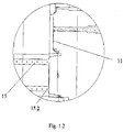
- This moulding space (11) which can be seen in greater detail in Figure 1.2 , is in the form of the seal in an open position of the cap (9) with respect to the frame (8) and with the cap (9) located on the frame (8) in the same vertical plane.
- the second phase (not shown in the figures) that follows is the injection of the material to make the seal (1) into the moulding space (11).
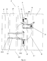
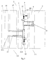
- the third phase is shown in Figures 2.1 and 3 and consists of the pre-expulsion of the manufactured seal (1).
- the seal (1) is separated from the fixed part (2.1) of the mould (2).
- this third seal (1) pre-expulsion phase involves a first horizontal movement of the floating plate (4) towards the moving part (2.2) of the mould (2), during which the joint movement of this moving part (2.2) of the mould (2) is generated, while the first moulding plate (5) remains fixed, joined to the first fixed base (3).
- the first horizontal movement of the floating plate (4) this occurs in two stages.
- the first stage can be seen in Figure 2.1 and involves the movement of the floating plate (4) and of a skid (13) on the fixed part (2,1) that accompanies the injected seal (1) in its movement over a horizontal distance H1.
- Figure 2.2 shows the injected seal in detail, which is pushed by the skid (13).
- the second stage consists of the horizontal movement of the floating plate (4) for a distance H2, where the skid (13) that accompanied the seal (1) in the first stage remains fixed during this second stage in the position reached in the first stage.
- Figure 5 shows the fifth phase in which the cap (9) is freed from the moving part (2.2) of the mould (2) and its descent on the frame (8) by the impulsion of compressed air (14) through a compressed air circuit (not shown in the figures) inside the mould (2).
- the hinged connection (10) between the cap (9) and the frame (8) is folded while the seal (1) is still fixed to part of the mould (2) and is still hot.
- the material of the seal (1) finishes crystallising in the closed position, avoiding the generation of stresses while closing the cap (9), thus considerably increasing the useful life of the hinged connection (10) and, therefore, of the seal (1).
- this freeing of the cap (9) involves a second horizontal movement of the expulsion assembly of the moving part (2.2) in the opposite direction of the first horizontal movement of the floating plate (4) and before the impulsion of compressed air (14). This second movement is over a distance H3.
- the expulsion assembly of the moving part consists of an expulsion element (15) for the seal (1) and a first and second moving plate.
- the first moving plate (16) is located in an intermediate position between the second fixed base (6) and the second moving plate (17) and the expulsion element (15) crosses through the second moulding plate (7) of the moving part (2.2) with a first end (15.1) connected to the first moving plate (16) and a second end (15.2) in contact with the injected seal (1).
- the sixth phase of the process then takes place, the final expulsion of the seal (1) from the mould (2) and its collection by an expulsion robot.
- this sixth phase involves a third horizontal movement of the first moving plate (16) of the moving part (2.2) and of the seal (1) expulsion element (15), in the same direction as the second horizontal movement of the expulsion assembly and for a distance H4.
- the second moving plate (17) remains fixed in the position reached after the second movement.
- this expulsion robot collects the injected seal (1) and makes a movement that presses the cap (9) on the frame (8) such that the seal (1) couplings fit and, likewise, the inviolability means are closed.
- the means for coupling the cap (9) to the frame (8) consist of several adjustment tabs (20) that couple together with one in the cap (9) and the other in the frame (8), in the areas of both opposite the hinged connection (10).
- the inviolability means are formed by a removable strip (21) in the frame (8) and an inviolability tab (22) that couples in it and located in the cap (9).
- the seal contains a dosing blade (18) fixed to the frame (8) and in addition the seal (1) includes fixing tongues (19) inside the cap (9) to hold this dosing blade (19) after its use.
- the product obtained is a closed seal in which no manual phase is involved at any time since it is completely automated.
Landscapes
- Engineering & Computer Science (AREA)
- Mechanical Engineering (AREA)
- Manufacturing & Machinery (AREA)
- Moulds For Moulding Plastics Or The Like (AREA)
- Closures For Containers (AREA)
Abstract
Description
- This invention belongs to the technical field of the injection moulding of seals for packaging, with moulds consisting of a fixed part and a moving part and in which the seal has a frame for connecting to the packaging, a cap and a hinged connection between both and means for coupling the cap to the frame as well as an additional tamperproof seal.
- Currently, many food product packages have seals consisting of a polyethylene cap but in recent years a type of seal has been introduced into the market that helps to preserve food in optimal conditions. These seals have a cap connected to a frame fixed to the packaging with the cap and frame connected by a hinge.
- This type of seal is manufactured by injection with the assembly consisting of the cap, frame and hinge forming a single piece. Normally, this type of seal includes a dosing blade fixed to the frame which is released from it for the first use, being then fixed to one of the tongues under the cap so that the user need not contact the powdered product to take it whenever it is to be used.
- The hinge connects the cap and the frame and is thinner to allow opening movements without breaking.
- The seal is injected open so that its later preparation must be undertaken in a manual closing phase for stacking and transport.
- This necessary manual handling of the pieces limits the productivity of the process since it greatly increases manufacturing time and increases the product's sanitary control tasks during its manufacture as well as increasing its cost.
- The reference documents
ES1069709 ES1029543 - The reference document
ES1069709 - The cap has a base containing the means for connecting to the opening in the packaging, an intermediate support coupled to the base and an element for opening and closing this intermediate support. In addition, the cap with all these elements is manufactured in a single piece of injected plastic with the base, the intermediate support and the opening and closing element made in the unfolded position.
- Thus, being manufactured in an unfolded position, it has the disadvantage that the opening and closing element and the intermediate support must be folded on the base to facilitate the transport and storage of these caps, requiring a phase to close the assembly which delays the process and increases production costs. In addition, the fact that the cap is closed after it has left the injection mould means that the plastic has cooled and therefore that the bending of the connection consisting of a thin and flexible strip forming a hinge generates stresses in this connector, material fatigue and, therefore, quicker breaking.
- Reference document
ES1029543 - In this case, the definition of a packaging seal consisting of an element connecting it and a cap can be seen again. Although this document does not state explicitly the way in which this is done, it does state that it is a single-piece body injected in plastic so that, logically, it must be injected in the open position given that otherwise the parts forming it would form a single block that would be impossible to open.
- Thus, the same disadvantages found in the previous document appear again, that is, a final manual phase is necessary to close the cap on the ring, which increases production times and makes the product more expensive. In addition, by closing the cap once the assembly has left the mould and the plastic has cooled, by bending the fine strip of plastic that forms the hinge, this undergoes stresses that reduce its strength as well as the number of openings and closings it can withstand before breaking. Therefore, this type of packaging seal usually always breaks at the hinge before the product in the packaging has been completely consumed.
- In the case of this second document, there is an added problem since it concerns packaging for containing a food product and must therefore comply with certain sanitary standards. Therefore, the fact that all the caps must be closed manually requires setting up sanitary protocols for all the processes that involve intermediate storage, transfer of material, etc, which logically make the end product more expensive and reduce its productivity.
- The process for making the seal for packaging by injection in a mould where the mould consists of a first fixed base a floating plate and a first moulding plate and a moving part with a second fixed base, an expulsion assembly and a second moulding plate, the seal being such that it includes a frame joining the packing, a cap and a hinged connection between both and where the seal includes means of coupling the cap to the frame and inviolability means for it as presented here, involves the phases described below.
- A first phase consists of the closure of the moving and fixed parts of the mould, forming a space for moulding the seal between the first and second moulding plates. This moulding space has the form of the seal in the open position of the cap with respect to the frame where the cap is located over the frame in the same vertical plane.
- Then there is a second phase of injection of material into the moulding space to make the seal.
- Once the seal has been made by injection, there is a third phase of its pre-expulsion with respect to the fixed part of the mould.
- Then, the fourth phase consists of the opening of the mould by the separation of the moving part in which the seal is held with respect to the fixed part.
- With the mould already open, there is a fifth phase of freeing the cap from the moving part of the mould and its descent over the frame by compressed air through a compressed air circuit located inside the mould.
- Finally, there is a sixth phase of the final expulsion of the seal from the mould and its collection by an expulsion robot. During the expulsion, this robot presses the cap on the frame so that it is fixed to it by coupling means and the means of inviolability are closed.
- In accordance with a preferred undertaking, the impulsion of compressed air undertaken in the phase of freeing the cap is undertaken on its upper level.
- In accordance with a preferred undertaking, the third phase of the pre-expulsion of the seal involves a first horizontal movement of the floating plate towards the moving part of the mould so that this moving part moves together with the floating plate and the first moulding plate remains fixed, connected to the first fixed base and a vertical movement of sliders in the moving part of the mould. Both the first horizontal movement and the vertical movement are undertaken simultaneously.
- These sliders hold the injected seal at its upper and lower ends. Their vertical movement is undertaken in the divergent direction with respect to the seal such that the seal is freed from these sliders.
- Thus, the first horizontal movement of the floating plate involves two stages, a first stage in which the floating plate moves for a horizontal distance H1 and a skid on the fixed part moves by this same horizontal distance H1 accompanying the injected seal in its movement and a second stage in which the floating plate moves for a horizontal distance H2 and this skid remains fixed in the position reached in the first stage.
- In accordance with another aspect and in a preferred undertaking, the fifth phase of freeing the cap involves a second horizontal movement of the expulsion assembly of the moving part.
- This expulsion assembly moves a distance H3 in the opposite direction to the first horizontal movement of the floating plate and before the compressed air impulsion. The second fixed base and the second moulding plate remain fixed in their positions.
- This expulsion assembly on the moving part consists of a seal expulsion element and a first and second moving plate. The first moving plate is located in an intermediate position between the second fixed base and the second moving plate and the expulsion element crosses through the second moulding plate of the moving part and presents a first end connected to the first moving plate and a second end in contact with the injected seal.
- In this case and in accordance with a preferred undertaking, the sixth phase of the final expulsion of the seal involves a third horizontal movement of a distance H4 in the same direction as the second horizontal movement of both the first moving plate of the moving part and the seal expulsion element. During this third horizontal movement, the second moving plate remains fixed in the position reached after the second movement.
- In accordance with a preferred undertaking, the means of coupling the cap to the frame consist of at least several adjustment tabs that couple together and are arranged in the cap and the frame, respectively.
- In accordance with a preferred undertaking, the inviolability means consist of a removable strip in the frame and an inviolability tab coupled to it and located in the cap.
- In a preferred undertaking, the seal contains a dosing blade inside it, fixed to the frame.
- In this case and in accordance with a preferred undertaking, the seal includes tongues fixing the dosing blade after its use inside the cap.
- With the process of manufacturing the seal for packaging by injection in a mould as proposed here, a significant improvement in the state of the technique is obtained.
- This is because a process for making these seals is achieved in which the cap and the frame of the seal are injected in a vertical position but in which the cap is closed on the frame immediately after injection.
- Thus, because.the cap is closed during the seal manufacture process itself, when it is extracted and because all is undertaken mechanically, a seal is obtained in which no human action is involved at any time and, therefore, its manufacture complies with the necessary sanitary conditions for use with food packaging without the need to apply costly sanitary processes that slow down the process.
- Likewise, since a final phase to close the cap on the frame is not needed, eliminating precisely this phase in which the human factor is much slower than the rest of the process, this is must quicker and an important increase in its productivity is obtained.
- In addition, costs are reduced by eliminating both labour and the exhaustive sanitary control required on these workers and the process undertaking times are reduced.
- Therefore, a seals manufacturing process is obtained that provides an important improvement over existing processes in the state of the technique since it eliminates their disadvantages and improves the productivity of the process.
- To help in the better understanding of the properties of the invention, in accordance with a preferred example of its practical undertaking, a series of drawings is supplied as an integral part of the description that are illustrative and not limiting, showing the following.
-
Figures 1.1 and1.2 . show a schematic view in cross section of the injection mould in a first phase of the process of manufacturing the packaging seal by injection in a mould and a detailed view A, respectively, for a preferred manner of undertaking the invention. -
Figures 2.1 and2.2 . show a schematic view in cross section of the injection mould in the first stage of the third phase of the process of manufacturing the packaging seal by injection in a mould and a detailed view B, respectively, for a preferred manner of undertaking the invention. -
Figure 3 shows a schematic view in cross section of the injection mould in the second stage of the third phase of the process of manufacturing the packaging seal by injection in a mould, for a preferred manner of undertaking the invention. -
Figure 4 shows a schematic view in cross section of the injection mould in a fourth phase of the process of manufacturing the packaging seal by injection in a mould, for a preferred manner of undertaking the invention. -
Figure 5 shows a schematic view in cross section of the injection mould in a fifth phase of the process of manufacturing the packaging seal by injection in a mould, for a preferred manner of undertaking the invention. -
Figures 6.1 and6.2 show a schematic view in cross section of the injection mould in a sixth phase of the process of manufacturing the packaging seal by injection in a mould and a detailed view C, respectively, for a preferred manner of undertaking the invention. - In the supplied figures, it can be seen how in a preferred manner of undertaking the invention, the process of manufacturing the seal (1) for packaging by injection in a mould proposed here, requires a mould (2) consisting of a fixed part (2.1) with a first fixed base (3), a floating plate (4) and a first moulding plate (5) and a moving part (2.2) with a second fixed base (6), an expulsion assembly and a second moulding plate (7) and where the seal (1) to be manufactured consists of a frame (8) connecting to the packaging, a cap (9) and a hinged connection (10) between both, as well as means of coupling the cap to the frame and means for its Inviolability.
- This manufacturing process involves the following phases.
- As shown in
Figure 1.1 , a first phase is the closure of the moving part (2.2) and the fixed part (2.1) of the mould (2). On closure, a moulding space (11) is generated between the first and second moulding plates (5, 7) with the shape of the seal (1). This moulding space (11), which can be seen in greater detail inFigure 1.2 , is in the form of the seal in an open position of the cap (9) with respect to the frame (8) and with the cap (9) located on the frame (8) in the same vertical plane. - The second phase (not shown in the figures) that follows is the injection of the material to make the seal (1) into the moulding space (11).
- The third phase is shown in
Figures 2.1 and3 and consists of the pre-expulsion of the manufactured seal (1). During this pre-expulsion phase, the seal (1) is separated from the fixed part (2.1) of the mould (2). - In this preferred manner of undertaking the invention, this third seal (1) pre-expulsion phase involves a first horizontal movement of the floating plate (4) towards the moving part (2.2) of the mould (2), during which the joint movement of this moving part (2.2) of the mould (2) is generated, while the first moulding plate (5) remains fixed, joined to the first fixed base (3).
- Likewise, as can be seen in
Figures 2.1 and3 , simultaneously with the first horizontal movement, there is a vertical movement of sliders (12) on the moving part (2.2) of the mould (2). - These sliders (12) hold the upper and lower ends of the injected seal (1) and move vertically away from the seal (1) such that these sliders (12) release its ends.
- Regarding the first horizontal movement of the floating plate (4), this occurs in two stages. The first stage can be seen in
Figure 2.1 and involves the movement of the floating plate (4) and of a skid (13) on the fixed part (2,1) that accompanies the injected seal (1) in its movement over a horizontal distance H1.Figure 2.2 , shows the injected seal in detail, which is pushed by the skid (13). - As shown in
Figure 3 , the second stage consists of the horizontal movement of the floating plate (4) for a distance H2, where the skid (13) that accompanied the seal (1) in the first stage remains fixed during this second stage in the position reached in the first stage. - There is then a fourth phase, shown in
Figure 4 , which consists of the opening of the mould (2) through the separation of the moving part (2.2) in which the (1) is held from the fixed part (2.1). -
Figure 5 shows the fifth phase in which the cap (9) is freed from the moving part (2.2) of the mould (2) and its descent on the frame (8) by the impulsion of compressed air (14) through a compressed air circuit (not shown in the figures) inside the mould (2). As the cap (9) descends, the hinged connection (10) between the cap (9) and the frame (8) is folded while the seal (1) is still fixed to part of the mould (2) and is still hot. Thus the material of the seal (1) finishes crystallising in the closed position, avoiding the generation of stresses while closing the cap (9), thus considerably increasing the useful life of the hinged connection (10) and, therefore, of the seal (1). - In this preferred manner of undertaking the invention this impulsion of compressed air (14) takes place on the upper level of the cap (9).
- As shown in
Figure 5 , in this preferred manner of undertaking the invention, this freeing of the cap (9) involves a second horizontal movement of the expulsion assembly of the moving part (2.2) in the opposite direction of the first horizontal movement of the floating plate (4) and before the impulsion of compressed air (14). This second movement is over a distance H3. - During this second movement, the second fixed base (6) and the second moulding plate (7) remain fixed in their positions.
- In this preferred manner of undertaking the invention, the expulsion assembly of the moving part consists of an expulsion element (15) for the seal (1) and a first and second moving plate. The first moving plate (16) is located in an intermediate position between the second fixed base (6) and the second moving plate (17) and the expulsion element (15) crosses through the second moulding plate (7) of the moving part (2.2) with a first end (15.1) connected to the first moving plate (16) and a second end (15.2) in contact with the injected seal (1).
- Thus, when the expulsion assembly moves and the second moulding plate (7) remains fixed, the expulsion element (15), in contact with the injected seal (1), pushes it, removing it from the second moulding plate (7).
- The sixth phase of the process then takes place, the final expulsion of the seal (1) from the mould (2) and its collection by an expulsion robot.
- In this preferred manner of undertaking the invention, as shown in
Figure 6.1 , this sixth phase involves a third horizontal movement of the first moving plate (16) of the moving part (2.2) and of the seal (1) expulsion element (15), in the same direction as the second horizontal movement of the expulsion assembly and for a distance H4. During this third horizontal movement, the second moving plate (17) remains fixed in the position reached after the second movement. - Thus, as can be seen in
Figure 6.2 , the injected seal (1) is fully extracted from the plates forming the moving part (2.2) of the mould (2), facilitating access to it by an expulsion robot (not shown in the figures). - Thus, this expulsion robot collects the injected seal (1) and makes a movement that presses the cap (9) on the frame (8) such that the seal (1) couplings fit and, likewise, the inviolability means are closed.
- In this preferred manner of undertaking the invention, as shown in
Figure 6.2 , the means for coupling the cap (9) to the frame (8) consist of several adjustment tabs (20) that couple together with one in the cap (9) and the other in the frame (8), in the areas of both opposite the hinged connection (10). - Likewise, in this preferred manner of undertaking the invention, the inviolability means are formed by a removable strip (21) in the frame (8) and an inviolability tab (22) that couples in it and located in the cap (9).
- In this preferred manner of undertaking the invention the seal contains a dosing blade (18) fixed to the frame (8) and in addition the seal (1) includes fixing tongues (19) inside the cap (9) to hold this dosing blade (19) after its use.
- The undertaking form described is only one example of this invention, so that the specific details, terms and phrases used in this memorandum must not be considered limiting but must be understood only as a base for the claims and as a representative base that provides an understandable description as well as sufficient information for the expert in the matter to apply this invention.
- With the process of manufacturing a packaging seal by injection in a mould presented here, important improvements are achieved with respect to the state of the technique.
- Firstly it must be emphasized that in the process described here, the product obtained is a closed seal in which no manual phase is involved at any time since it is completely automated.
- This great advantage gives greater speed in undertaking the complete process, a reduction in sanitary control costs since the product is not handled by the workers and, therefore greater process productivity.
- An additional advantage is also obtained that is of great relevance since by closing the cap on the frame while these are still fixed to the moving part of the mould, which was just opened after making the seal, this seal has not had time to cool or crystallise completely so that the hinged connection is folded to close the cap and is in this position when the material of which the seal is made finishes crystallising. Thus the internal stresses in the area of the hinged connection are eliminated, preventing reductions in its strength that cause the early breaking of the hinged connection.
- This is therefore a very effective process for manufacturing seals which achieves the closed seal simply and without increasing undertaking times, increasing sanitary conditions and reducing costs.
Claims (9)
- Process for manufacturing the seal (1) for packaging by injection in a mould, in which the mould (2) consists of a fixed part (2.1) with a first fixed base (3), a floating plate (4) and a first moulding plate (5) and a moving part (2.2) with a second fixed base (6), an expulsion assembly and a second moulding plate (7), the seal (1) consisting of a frame (8) connecting to the packaging, a cap (9), a hinged connection (10) between both, means of coupling the cap (9) to the frame (8) and means for its inviolability, featuring the following phases- closure of the moving part (2.2) and the fixed part (2.1) of the mould (2), forming between the first and the second moulding plates (5, 7) a moulding space (11) for the seal (1) with the cap (9) in the open position with respect to the frame (8), where the cap (9) is located over the frame (8) in the same vertical plane;- injection of the material to make the seal (1) into the moulding space (11);- pre-expulsion of the seal (1) from the fixed part (2.1) of the mould (2);- opening of the mould (2) through the separation of the moving part (2.2) in which the seal (1) is fixed from the fixed part (2.1);- freeing of the cap (9) from the moving part (2.2) of the mould (2) and its descent on the frame (8) through the impulsion of compressed air (14) through a compressed air circuit located in the mould (2), and;- final expulsion of the seal (1) from the mould and its collection by an expulsion robot;- in which during the expulsion this robot presses the cap (9) on the frame (8) so that it is fixed to it by coupling means and the inviolability means are closed.
- Process for manufacturing the seal (1) for packaging by injection in a mould, as in claim 1, featuring the impulsion of compressed air (14) on the upper level of the cap (9).
- Process for manufacturing the seal (1) for packaging by injection in a mould, as in any of the above claims, featuring the pre-expulsion of the seal (1) consisting of a first horizontal movement of the floating plate (4) towards the moving part (2.2) of the mould (2), where this moving part (2.2) moves together with the floating plate (4) and the first moulding plate (5) remains fixed, joined to the first fixed base (3) and a vertical movement of sliders (12) in the moving part (2.2) of the mould (2) that hold the injected seal (1) at its upper and lower ends, this vertical movement being in the divergent direction with respect to the seal (1) such that these sliders (12) release its ends, where both movements are made simultaneously and where the first horizontal movement of the floating plate (4) presents a first stage in which this floating plate (4) moves for a horizontal distance H1 and where a skid (13) on the fixed part (2.1) moves by this same horizontal distance H1 accompanying the injected seal (1) in its movement and a second stage in which the floating plate (4) moves by a horizontal distance H2 and this skid (13) remains fixed in the position reached in the first stage.
- Process for manufacturing the seal (1) for packaging by injection in a mould, as in any of the above claims, featuring the freeing of the cap (9) with a second horizontal movement of the expulsion assembly on the moving part (2.2), such that this expulsion assembly moves by a distance H3 with respect to the second fixed base (6) and the second moulding plate (7) which remain fixed in their positions, in the opposite direction to the first horizontal movement of the floating plate (4) and before the impulsion of compressed air (14), where the expulsion assembly on the moving part (2.2) consists of a seal (1) expulsion element (15) and a second moving plate, the first moving plate (16) being in an intermediate position between the second fixed base (6) and the second moving plate (17), where the expulsion element (15) crosses through the second moulding plate (7) of the moving part (2.2) and has a first end (15.1) connected to the first moving plate (16) and a second end (15.2) in contact with the injected seal (1).
- Process for manufacturing the seal (1) for packaging by injection in a mould, as in claim 4, featuring the final expulsion of the seal (1) with a third horizontal movement for a distance H4 in the same direction as the second horizontal movement, of the first moving plate (16) and of the seal expulsion element (15), where the second moving plate (17) remains fixed in the position reached after that second movement.
- Process for manufacturing the seal (1) for packaging by injection in a mould, as in any of the above claims, featuring the means for coupling the cap (9) to the frame (8) being formed of at least several adjustment tabs (20) that couple together and are arranged in the cap (9) and the frame (8), respectively.
- Process for manufacturing the seal (1) for packaging by injection in a mould, as in any of the above claims, featuring the inviolability means formed by a removable strip (21) in the frame (8) and an inviolability tab (22) coupled in it and located in the cap (9).
- Process for manufacturing the seal (1) for packaging by injection in a mould, as in any of the above claims, featuring the seal (1) with a dosing blade (18) inside it, fixed to the frame (8).
- Process for manufacturing the seal (1) for packaging by injection in a mould, as in claim 8, featuring the seal (1) with fixing tongues (19) for the dosing blade (18) after its use, inside the cap (9).
Priority Applications (4)
| Application Number | Priority Date | Filing Date | Title |
|---|---|---|---|
| PT16001773T PT3281759T (en) | 2016-08-10 | 2016-08-10 | Process for making seals for packaging by injection in mould |
| ES16001773.7T ES2692156T3 (en) | 2016-08-10 | 2016-08-10 | Process of sealing execution for container by injection in mold |
| TR2018/15763T TR201815763T4 (en) | 2016-08-10 | 2016-08-10 | Process for making insulating elements for packaging by injection molding. |
| EP16001773.7A EP3281759B1 (en) | 2016-08-10 | 2016-08-10 | Process for making seals for packaging by injection in mould |
Applications Claiming Priority (1)
| Application Number | Priority Date | Filing Date | Title |
|---|---|---|---|
| EP16001773.7A EP3281759B1 (en) | 2016-08-10 | 2016-08-10 | Process for making seals for packaging by injection in mould |
Publications (2)
| Publication Number | Publication Date |
|---|---|
| EP3281759A1 true EP3281759A1 (en) | 2018-02-14 |
| EP3281759B1 EP3281759B1 (en) | 2018-07-25 |
Family
ID=56681920
Family Applications (1)
| Application Number | Title | Priority Date | Filing Date |
|---|---|---|---|
| EP16001773.7A Active EP3281759B1 (en) | 2016-08-10 | 2016-08-10 | Process for making seals for packaging by injection in mould |
Country Status (4)
| Country | Link |
|---|---|
| EP (1) | EP3281759B1 (en) |
| ES (1) | ES2692156T3 (en) |
| PT (1) | PT3281759T (en) |
| TR (1) | TR201815763T4 (en) |
Cited By (1)
| Publication number | Priority date | Publication date | Assignee | Title |
|---|---|---|---|---|
| EP3546170A1 (en) * | 2018-03-28 | 2019-10-02 | 3M Innovative Properties Company | A method of forming a flip-top cap and a flip-top cap |
Citations (9)
| Publication number | Priority date | Publication date | Assignee | Title |
|---|---|---|---|---|
| US2875472A (en) * | 1957-03-26 | 1959-03-03 | Marcus William | Molding apparatus for container covers |
| US3537676A (en) * | 1967-12-20 | 1970-11-03 | Valve Corp Of America | Mold apparatus for closure with integral cap |
| US4351630A (en) * | 1980-12-31 | 1982-09-28 | Global Precision Inc. | Pivoting hinge exercising mechanism |
| JPS61255823A (en) * | 1985-05-08 | 1986-11-13 | Yoshino Kogyosho Co Ltd | Method and apparatus for demolding cap made of synthetic resin |
| ES1029543U (en) | 1994-11-30 | 1995-05-16 | Fernandez Manuel Lopez | Complementary closure device for containers boat type and the like. (Machine-translation by Google Translate, not legally binding) |
| US20080260890A1 (en) * | 2007-04-17 | 2008-10-23 | Husky Injection Molding Systems Ltd. | Apparatus for Folding and Removing a Hinged Molded Part and Associated Method of Use |
| ES1069709U (en) | 2009-02-17 | 2009-05-01 | ARBORA & AUSONIA S.L.U | Cover for disposable containers of wetting towels (Machine-translation by Google Translate, not legally binding) |
| WO2009111854A1 (en) * | 2008-03-12 | 2009-09-17 | Stack Teck Systems Limited | In-mold closing mechanism and method |
| WO2013178234A1 (en) * | 2012-05-29 | 2013-12-05 | Aptar Freyung Gmbh | Dispensing closure |
-
2016
- 2016-08-10 EP EP16001773.7A patent/EP3281759B1/en active Active
- 2016-08-10 ES ES16001773.7T patent/ES2692156T3/en active Active
- 2016-08-10 PT PT16001773T patent/PT3281759T/en unknown
- 2016-08-10 TR TR2018/15763T patent/TR201815763T4/en unknown
Patent Citations (9)
| Publication number | Priority date | Publication date | Assignee | Title |
|---|---|---|---|---|
| US2875472A (en) * | 1957-03-26 | 1959-03-03 | Marcus William | Molding apparatus for container covers |
| US3537676A (en) * | 1967-12-20 | 1970-11-03 | Valve Corp Of America | Mold apparatus for closure with integral cap |
| US4351630A (en) * | 1980-12-31 | 1982-09-28 | Global Precision Inc. | Pivoting hinge exercising mechanism |
| JPS61255823A (en) * | 1985-05-08 | 1986-11-13 | Yoshino Kogyosho Co Ltd | Method and apparatus for demolding cap made of synthetic resin |
| ES1029543U (en) | 1994-11-30 | 1995-05-16 | Fernandez Manuel Lopez | Complementary closure device for containers boat type and the like. (Machine-translation by Google Translate, not legally binding) |
| US20080260890A1 (en) * | 2007-04-17 | 2008-10-23 | Husky Injection Molding Systems Ltd. | Apparatus for Folding and Removing a Hinged Molded Part and Associated Method of Use |
| WO2009111854A1 (en) * | 2008-03-12 | 2009-09-17 | Stack Teck Systems Limited | In-mold closing mechanism and method |
| ES1069709U (en) | 2009-02-17 | 2009-05-01 | ARBORA & AUSONIA S.L.U | Cover for disposable containers of wetting towels (Machine-translation by Google Translate, not legally binding) |
| WO2013178234A1 (en) * | 2012-05-29 | 2013-12-05 | Aptar Freyung Gmbh | Dispensing closure |
Cited By (2)
| Publication number | Priority date | Publication date | Assignee | Title |
|---|---|---|---|---|
| EP3546170A1 (en) * | 2018-03-28 | 2019-10-02 | 3M Innovative Properties Company | A method of forming a flip-top cap and a flip-top cap |
| WO2019186327A1 (en) * | 2018-03-28 | 2019-10-03 | 3M Innovative Properties Company | A method of forming a flip-top cap and a flip-top cap |
Also Published As
| Publication number | Publication date |
|---|---|
| TR201815763T4 (en) | 2018-11-21 |
| PT3281759T (en) | 2018-10-30 |
| EP3281759B1 (en) | 2018-07-25 |
| ES2692156T3 (en) | 2018-11-30 |
Similar Documents
| Publication | Publication Date | Title |
|---|---|---|
| JP3942196B2 (en) | Recloseable container and method for manufacturing the same | |
| CN102933468B (en) | tamper warning bottle cap | |
| US9828146B2 (en) | Tamper evident flip-top closure, method and tool for making the same | |
| CA2574036A1 (en) | Tamper-indicating dispensing closure | |
| JP2018519051A5 (en) | ||
| BR112018012709B1 (en) | CAN LID | |
| CN103079965A (en) | A package closure and a device and a method for producing a package closure | |
| EP0605617A1 (en) | Apparatus for and method of making an injection molded frame having a panel insert | |
| IT9068016A1 (en) | PROCEDURE AND DEVICE FOR THE FORMING OF THE GUARANTEE BAND OF A CLOSING CAP | |
| EP3281759A1 (en) | Process for making seals for packaging by injection in mould | |
| CN102574613B (en) | A closure | |
| ITMI20101243A1 (en) | "DISPENSER PLUG WITH AUTOMATIC VALVE FOR CONTAINERS TO CARRY AND DELIVER LIQUID OR CREMOSE SUBSTANCES" | |
| RU2016149539A (en) | COOKING DEVICE, METHOD FOR MANUFACTURING A COOKING DEVICE AND A PACKAGING CONTAINER HAVING SUCH A COOKING DEVICE | |
| SE544254C2 (en) | A package closure and a method for producing a package closure | |
| EP3853141B1 (en) | Tethered plastic stopper | |
| EP2190750B1 (en) | Re-closable container for fluid products | |
| US20250051060A1 (en) | Package closures and methods and devices for producing package closures | |
| EP2106370B1 (en) | Process for making plastic closures | |
| EP2314444A1 (en) | A closure | |
| JP3086079B2 (en) | Container lid and method of manufacturing the same | |
| NO791255L (en) | COMPOSITE CONTAINER. | |
| CN110668003A (en) | Safe and reliable's combination bottle lid and container | |
| WO2007144741A1 (en) | Process for manufacturing bottles for fluid products, particularly pharmaceutical, medicinal and cosmetic products | |
| JP2003165556A (en) | Cap for separated collection with cavity part | |
| EP2314520A1 (en) | A closure |
Legal Events
| Date | Code | Title | Description |
|---|---|---|---|
| PUAI | Public reference made under article 153(3) epc to a published international application that has entered the european phase |
Free format text: ORIGINAL CODE: 0009012 |
|
| 17P | Request for examination filed |
Effective date: 20160815 |
|
| AK | Designated contracting states |
Kind code of ref document: A1 Designated state(s): AL AT BE BG CH CY CZ DE DK EE ES FI FR GB GR HR HU IE IS IT LI LT LU LV MC MK MT NL NO PL PT RO RS SE SI SK SM TR |
|
| AX | Request for extension of the european patent |
Extension state: BA ME |
|
| GRAP | Despatch of communication of intention to grant a patent |
Free format text: ORIGINAL CODE: EPIDOSNIGR1 |
|
| INTG | Intention to grant announced |
Effective date: 20180227 |
|
| GRAS | Grant fee paid |
Free format text: ORIGINAL CODE: EPIDOSNIGR3 |
|
| GRAA | (expected) grant |
Free format text: ORIGINAL CODE: 0009210 |
|
| AK | Designated contracting states |
Kind code of ref document: B1 Designated state(s): AL AT BE BG CH CY CZ DE DK EE ES FI FR GB GR HR HU IE IS IT LI LT LU LV MC MK MT NL NO PL PT RO RS SE SI SK SM TR |
|
| REG | Reference to a national code |
Ref country code: GB Ref legal event code: FG4D |
|
| REG | Reference to a national code |
Ref country code: CH Ref legal event code: EP |
|
| REG | Reference to a national code |
Ref country code: AT Ref legal event code: REF Ref document number: 1021279 Country of ref document: AT Kind code of ref document: T Effective date: 20180815 |
|
| REG | Reference to a national code |
Ref country code: IE Ref legal event code: FG4D |
|
| REG | Reference to a national code |
Ref country code: DE Ref legal event code: R096 Ref document number: 602016004170 Country of ref document: DE |
|
| REG | Reference to a national code |
Ref country code: PT Ref legal event code: SC4A Ref document number: 3281759 Country of ref document: PT Date of ref document: 20181030 Kind code of ref document: T Free format text: AVAILABILITY OF NATIONAL TRANSLATION Effective date: 20181023 |
|
| REG | Reference to a national code |
Ref country code: CH Ref legal event code: NV Representative=s name: JUNOD, MUHLSTEIN, LEVY AND PUDER, AVOCATS, CH |
|
| REG | Reference to a national code |
Ref country code: NL Ref legal event code: FP |
|
| REG | Reference to a national code |
Ref country code: ES Ref legal event code: FG2A Ref document number: 2692156 Country of ref document: ES Kind code of ref document: T3 Effective date: 20181130 |
|
| REG | Reference to a national code |
Ref country code: LT Ref legal event code: MG4D |
|
| PG25 | Lapsed in a contracting state [announced via postgrant information from national office to epo] |
Ref country code: FI Free format text: LAPSE BECAUSE OF FAILURE TO SUBMIT A TRANSLATION OF THE DESCRIPTION OR TO PAY THE FEE WITHIN THE PRESCRIBED TIME-LIMIT Effective date: 20180725 Ref country code: IS Free format text: LAPSE BECAUSE OF FAILURE TO SUBMIT A TRANSLATION OF THE DESCRIPTION OR TO PAY THE FEE WITHIN THE PRESCRIBED TIME-LIMIT Effective date: 20181125 Ref country code: NO Free format text: LAPSE BECAUSE OF FAILURE TO SUBMIT A TRANSLATION OF THE DESCRIPTION OR TO PAY THE FEE WITHIN THE PRESCRIBED TIME-LIMIT Effective date: 20181025 Ref country code: SE Free format text: LAPSE BECAUSE OF FAILURE TO SUBMIT A TRANSLATION OF THE DESCRIPTION OR TO PAY THE FEE WITHIN THE PRESCRIBED TIME-LIMIT Effective date: 20180725 Ref country code: BG Free format text: LAPSE BECAUSE OF FAILURE TO SUBMIT A TRANSLATION OF THE DESCRIPTION OR TO PAY THE FEE WITHIN THE PRESCRIBED TIME-LIMIT Effective date: 20181025 Ref country code: GR Free format text: LAPSE BECAUSE OF FAILURE TO SUBMIT A TRANSLATION OF THE DESCRIPTION OR TO PAY THE FEE WITHIN THE PRESCRIBED TIME-LIMIT Effective date: 20181026 Ref country code: RS Free format text: LAPSE BECAUSE OF FAILURE TO SUBMIT A TRANSLATION OF THE DESCRIPTION OR TO PAY THE FEE WITHIN THE PRESCRIBED TIME-LIMIT Effective date: 20180725 Ref country code: LT Free format text: LAPSE BECAUSE OF FAILURE TO SUBMIT A TRANSLATION OF THE DESCRIPTION OR TO PAY THE FEE WITHIN THE PRESCRIBED TIME-LIMIT Effective date: 20180725 Ref country code: PL Free format text: LAPSE BECAUSE OF FAILURE TO SUBMIT A TRANSLATION OF THE DESCRIPTION OR TO PAY THE FEE WITHIN THE PRESCRIBED TIME-LIMIT Effective date: 20180725 |
|
| PG25 | Lapsed in a contracting state [announced via postgrant information from national office to epo] |
Ref country code: AL Free format text: LAPSE BECAUSE OF FAILURE TO SUBMIT A TRANSLATION OF THE DESCRIPTION OR TO PAY THE FEE WITHIN THE PRESCRIBED TIME-LIMIT Effective date: 20180725 Ref country code: LV Free format text: LAPSE BECAUSE OF FAILURE TO SUBMIT A TRANSLATION OF THE DESCRIPTION OR TO PAY THE FEE WITHIN THE PRESCRIBED TIME-LIMIT Effective date: 20180725 Ref country code: HR Free format text: LAPSE BECAUSE OF FAILURE TO SUBMIT A TRANSLATION OF THE DESCRIPTION OR TO PAY THE FEE WITHIN THE PRESCRIBED TIME-LIMIT Effective date: 20180725 |
|
| REG | Reference to a national code |
Ref country code: DE Ref legal event code: R097 Ref document number: 602016004170 Country of ref document: DE |
|
| PG25 | Lapsed in a contracting state [announced via postgrant information from national office to epo] |
Ref country code: MC Free format text: LAPSE BECAUSE OF FAILURE TO SUBMIT A TRANSLATION OF THE DESCRIPTION OR TO PAY THE FEE WITHIN THE PRESCRIBED TIME-LIMIT Effective date: 20180725 Ref country code: RO Free format text: LAPSE BECAUSE OF FAILURE TO SUBMIT A TRANSLATION OF THE DESCRIPTION OR TO PAY THE FEE WITHIN THE PRESCRIBED TIME-LIMIT Effective date: 20180725 Ref country code: LU Free format text: LAPSE BECAUSE OF NON-PAYMENT OF DUE FEES Effective date: 20180810 Ref country code: EE Free format text: LAPSE BECAUSE OF FAILURE TO SUBMIT A TRANSLATION OF THE DESCRIPTION OR TO PAY THE FEE WITHIN THE PRESCRIBED TIME-LIMIT Effective date: 20180725 Ref country code: CZ Free format text: LAPSE BECAUSE OF FAILURE TO SUBMIT A TRANSLATION OF THE DESCRIPTION OR TO PAY THE FEE WITHIN THE PRESCRIBED TIME-LIMIT Effective date: 20180725 |
|
| REG | Reference to a national code |
Ref country code: IE Ref legal event code: MM4A |
|
| PG25 | Lapsed in a contracting state [announced via postgrant information from national office to epo] |
Ref country code: DK Free format text: LAPSE BECAUSE OF FAILURE TO SUBMIT A TRANSLATION OF THE DESCRIPTION OR TO PAY THE FEE WITHIN THE PRESCRIBED TIME-LIMIT Effective date: 20180725 Ref country code: SM Free format text: LAPSE BECAUSE OF FAILURE TO SUBMIT A TRANSLATION OF THE DESCRIPTION OR TO PAY THE FEE WITHIN THE PRESCRIBED TIME-LIMIT Effective date: 20180725 Ref country code: SK Free format text: LAPSE BECAUSE OF FAILURE TO SUBMIT A TRANSLATION OF THE DESCRIPTION OR TO PAY THE FEE WITHIN THE PRESCRIBED TIME-LIMIT Effective date: 20180725 |
|
| PLBE | No opposition filed within time limit |
Free format text: ORIGINAL CODE: 0009261 |
|
| STAA | Information on the status of an ep patent application or granted ep patent |
Free format text: STATUS: NO OPPOSITION FILED WITHIN TIME LIMIT |
|
| 26N | No opposition filed |
Effective date: 20190426 |
|
| PG25 | Lapsed in a contracting state [announced via postgrant information from national office to epo] |
Ref country code: IE Free format text: LAPSE BECAUSE OF NON-PAYMENT OF DUE FEES Effective date: 20180810 |
|
| PG25 | Lapsed in a contracting state [announced via postgrant information from national office to epo] |
Ref country code: SI Free format text: LAPSE BECAUSE OF FAILURE TO SUBMIT A TRANSLATION OF THE DESCRIPTION OR TO PAY THE FEE WITHIN THE PRESCRIBED TIME-LIMIT Effective date: 20180725 |
|
| PG25 | Lapsed in a contracting state [announced via postgrant information from national office to epo] |
Ref country code: MT Free format text: LAPSE BECAUSE OF NON-PAYMENT OF DUE FEES Effective date: 20180810 |
|
| PG25 | Lapsed in a contracting state [announced via postgrant information from national office to epo] |
Ref country code: HU Free format text: LAPSE BECAUSE OF FAILURE TO SUBMIT A TRANSLATION OF THE DESCRIPTION OR TO PAY THE FEE WITHIN THE PRESCRIBED TIME-LIMIT; INVALID AB INITIO Effective date: 20160810 Ref country code: CY Free format text: LAPSE BECAUSE OF FAILURE TO SUBMIT A TRANSLATION OF THE DESCRIPTION OR TO PAY THE FEE WITHIN THE PRESCRIBED TIME-LIMIT Effective date: 20180725 Ref country code: MK Free format text: LAPSE BECAUSE OF NON-PAYMENT OF DUE FEES Effective date: 20180725 |
|
| GBPC | Gb: european patent ceased through non-payment of renewal fee |
Effective date: 20200810 |
|
| REG | Reference to a national code |
Ref country code: AT Ref legal event code: UEP Ref document number: 1021279 Country of ref document: AT Kind code of ref document: T Effective date: 20180725 |
|
| PG25 | Lapsed in a contracting state [announced via postgrant information from national office to epo] |
Ref country code: GB Free format text: LAPSE BECAUSE OF NON-PAYMENT OF DUE FEES Effective date: 20200810 |
|
| P01 | Opt-out of the competence of the unified patent court (upc) registered |
Effective date: 20230529 |
|
| PGFP | Annual fee paid to national office [announced via postgrant information from national office to epo] |
Ref country code: NL Payment date: 20250805 Year of fee payment: 10 |
|
| PGFP | Annual fee paid to national office [announced via postgrant information from national office to epo] |
Ref country code: ES Payment date: 20250909 Year of fee payment: 10 Ref country code: PT Payment date: 20250723 Year of fee payment: 10 |
|
| PGFP | Annual fee paid to national office [announced via postgrant information from national office to epo] |
Ref country code: DE Payment date: 20250819 Year of fee payment: 10 |
|
| PGFP | Annual fee paid to national office [announced via postgrant information from national office to epo] |
Ref country code: TR Payment date: 20250723 Year of fee payment: 10 Ref country code: IT Payment date: 20250728 Year of fee payment: 10 |
|
| PGFP | Annual fee paid to national office [announced via postgrant information from national office to epo] |
Ref country code: BE Payment date: 20250729 Year of fee payment: 10 |
|
| PGFP | Annual fee paid to national office [announced via postgrant information from national office to epo] |
Ref country code: FR Payment date: 20250723 Year of fee payment: 10 Ref country code: AT Payment date: 20250808 Year of fee payment: 10 |
|
| PGFP | Annual fee paid to national office [announced via postgrant information from national office to epo] |
Ref country code: CH Payment date: 20250901 Year of fee payment: 10 |