EP3281659A1 - Apparatus and system for fluid delivery - Google Patents
Apparatus and system for fluid delivery Download PDFInfo
- Publication number
- EP3281659A1 EP3281659A1 EP17173314.0A EP17173314A EP3281659A1 EP 3281659 A1 EP3281659 A1 EP 3281659A1 EP 17173314 A EP17173314 A EP 17173314A EP 3281659 A1 EP3281659 A1 EP 3281659A1
- Authority
- EP
- European Patent Office
- Prior art keywords
- slider
- housing
- fluid
- mandrel
- sleeve
- Prior art date
- Legal status (The legal status is an assumption and is not a legal conclusion. Google has not performed a legal analysis and makes no representation as to the accuracy of the status listed.)
- Granted
Links
Images




Classifications
-
- A—HUMAN NECESSITIES
- A61—MEDICAL OR VETERINARY SCIENCE; HYGIENE
- A61M—DEVICES FOR INTRODUCING MEDIA INTO, OR ONTO, THE BODY; DEVICES FOR TRANSDUCING BODY MEDIA OR FOR TAKING MEDIA FROM THE BODY; DEVICES FOR PRODUCING OR ENDING SLEEP OR STUPOR
- A61M5/00—Devices for bringing media into the body in a subcutaneous, intra-vascular or intramuscular way; Accessories therefor, e.g. filling or cleaning devices, arm rests
- A61M5/178—Syringes
- A61M5/31—Details
- A61M5/315—Pistons; Piston-rods; Guiding, blocking or restricting the movement of the rod or piston; Appliances on the rod for facilitating dosing ; Dosing mechanisms
- A61M5/31511—Piston or piston-rod constructions, e.g. connection of piston with piston-rod
-
- A—HUMAN NECESSITIES
- A61—MEDICAL OR VETERINARY SCIENCE; HYGIENE
- A61M—DEVICES FOR INTRODUCING MEDIA INTO, OR ONTO, THE BODY; DEVICES FOR TRANSDUCING BODY MEDIA OR FOR TAKING MEDIA FROM THE BODY; DEVICES FOR PRODUCING OR ENDING SLEEP OR STUPOR
- A61M5/00—Devices for bringing media into the body in a subcutaneous, intra-vascular or intramuscular way; Accessories therefor, e.g. filling or cleaning devices, arm rests
- A61M5/14—Infusion devices, e.g. infusing by gravity; Blood infusion; Accessories therefor
- A61M5/168—Means for controlling media flow to the body or for metering media to the body, e.g. drip meters, counters
- A61M5/16877—Passive flow controllers; Devices for setting a flow rate
- A61M5/16881—Regulating valves
-
- A—HUMAN NECESSITIES
- A61—MEDICAL OR VETERINARY SCIENCE; HYGIENE
- A61M—DEVICES FOR INTRODUCING MEDIA INTO, OR ONTO, THE BODY; DEVICES FOR TRANSDUCING BODY MEDIA OR FOR TAKING MEDIA FROM THE BODY; DEVICES FOR PRODUCING OR ENDING SLEEP OR STUPOR
- A61M5/00—Devices for bringing media into the body in a subcutaneous, intra-vascular or intramuscular way; Accessories therefor, e.g. filling or cleaning devices, arm rests
- A61M5/14—Infusion devices, e.g. infusing by gravity; Blood infusion; Accessories therefor
- A61M5/142—Pressure infusion, e.g. using pumps
- A61M5/145—Pressure infusion, e.g. using pumps using pressurised reservoirs, e.g. by means of pistons
- A61M5/1452—Pressure infusion, e.g. using pumps using pressurised reservoirs, e.g. by means of pistons pressurised by means of pistons
- A61M5/14566—Pressure infusion, e.g. using pumps using pressurised reservoirs, e.g. by means of pistons pressurised by means of pistons with a replaceable reservoir for receiving a piston rod of the pump
-
- A—HUMAN NECESSITIES
- A61—MEDICAL OR VETERINARY SCIENCE; HYGIENE
- A61M—DEVICES FOR INTRODUCING MEDIA INTO, OR ONTO, THE BODY; DEVICES FOR TRANSDUCING BODY MEDIA OR FOR TAKING MEDIA FROM THE BODY; DEVICES FOR PRODUCING OR ENDING SLEEP OR STUPOR
- A61M39/00—Tubes, tube connectors, tube couplings, valves, access sites or the like, specially adapted for medical use
- A61M39/22—Valves or arrangement of valves
- A61M39/28—Clamping means for squeezing flexible tubes, e.g. roller clamps
- A61M39/286—Wedge clamps, e.g. roller clamps with inclined guides
- A61M39/287—Wedge formed by a slot having varying width, e.g. slide clamps
-
- A—HUMAN NECESSITIES
- A61—MEDICAL OR VETERINARY SCIENCE; HYGIENE
- A61M—DEVICES FOR INTRODUCING MEDIA INTO, OR ONTO, THE BODY; DEVICES FOR TRANSDUCING BODY MEDIA OR FOR TAKING MEDIA FROM THE BODY; DEVICES FOR PRODUCING OR ENDING SLEEP OR STUPOR
- A61M5/00—Devices for bringing media into the body in a subcutaneous, intra-vascular or intramuscular way; Accessories therefor, e.g. filling or cleaning devices, arm rests
- A61M5/14—Infusion devices, e.g. infusing by gravity; Blood infusion; Accessories therefor
- A61M5/142—Pressure infusion, e.g. using pumps
- A61M5/14244—Pressure infusion, e.g. using pumps adapted to be carried by the patient, e.g. portable on the body
-
- A—HUMAN NECESSITIES
- A61—MEDICAL OR VETERINARY SCIENCE; HYGIENE
- A61M—DEVICES FOR INTRODUCING MEDIA INTO, OR ONTO, THE BODY; DEVICES FOR TRANSDUCING BODY MEDIA OR FOR TAKING MEDIA FROM THE BODY; DEVICES FOR PRODUCING OR ENDING SLEEP OR STUPOR
- A61M5/00—Devices for bringing media into the body in a subcutaneous, intra-vascular or intramuscular way; Accessories therefor, e.g. filling or cleaning devices, arm rests
- A61M5/14—Infusion devices, e.g. infusing by gravity; Blood infusion; Accessories therefor
- A61M5/142—Pressure infusion, e.g. using pumps
- A61M5/145—Pressure infusion, e.g. using pumps using pressurised reservoirs, e.g. by means of pistons
- A61M5/1452—Pressure infusion, e.g. using pumps using pressurised reservoirs, e.g. by means of pistons pressurised by means of pistons
-
- A—HUMAN NECESSITIES
- A61—MEDICAL OR VETERINARY SCIENCE; HYGIENE
- A61M—DEVICES FOR INTRODUCING MEDIA INTO, OR ONTO, THE BODY; DEVICES FOR TRANSDUCING BODY MEDIA OR FOR TAKING MEDIA FROM THE BODY; DEVICES FOR PRODUCING OR ENDING SLEEP OR STUPOR
- A61M5/00—Devices for bringing media into the body in a subcutaneous, intra-vascular or intramuscular way; Accessories therefor, e.g. filling or cleaning devices, arm rests
- A61M5/14—Infusion devices, e.g. infusing by gravity; Blood infusion; Accessories therefor
- A61M5/142—Pressure infusion, e.g. using pumps
- A61M5/145—Pressure infusion, e.g. using pumps using pressurised reservoirs, e.g. by means of pistons
- A61M5/1452—Pressure infusion, e.g. using pumps using pressurised reservoirs, e.g. by means of pistons pressurised by means of pistons
- A61M5/1456—Pressure infusion, e.g. using pumps using pressurised reservoirs, e.g. by means of pistons pressurised by means of pistons with a replaceable reservoir comprising a piston rod to be moved into the reservoir, e.g. the piston rod is part of the removable reservoir
-
- A—HUMAN NECESSITIES
- A61—MEDICAL OR VETERINARY SCIENCE; HYGIENE
- A61M—DEVICES FOR INTRODUCING MEDIA INTO, OR ONTO, THE BODY; DEVICES FOR TRANSDUCING BODY MEDIA OR FOR TAKING MEDIA FROM THE BODY; DEVICES FOR PRODUCING OR ENDING SLEEP OR STUPOR
- A61M5/00—Devices for bringing media into the body in a subcutaneous, intra-vascular or intramuscular way; Accessories therefor, e.g. filling or cleaning devices, arm rests
- A61M5/14—Infusion devices, e.g. infusing by gravity; Blood infusion; Accessories therefor
- A61M5/168—Means for controlling media flow to the body or for metering media to the body, e.g. drip meters, counters
- A61M5/16804—Active flow controllers
-
- A—HUMAN NECESSITIES
- A61—MEDICAL OR VETERINARY SCIENCE; HYGIENE
- A61M—DEVICES FOR INTRODUCING MEDIA INTO, OR ONTO, THE BODY; DEVICES FOR TRANSDUCING BODY MEDIA OR FOR TAKING MEDIA FROM THE BODY; DEVICES FOR PRODUCING OR ENDING SLEEP OR STUPOR
- A61M5/00—Devices for bringing media into the body in a subcutaneous, intra-vascular or intramuscular way; Accessories therefor, e.g. filling or cleaning devices, arm rests
- A61M5/14—Infusion devices, e.g. infusing by gravity; Blood infusion; Accessories therefor
- A61M5/168—Means for controlling media flow to the body or for metering media to the body, e.g. drip meters, counters
- A61M5/16831—Monitoring, detecting, signalling or eliminating infusion flow anomalies
-
- A—HUMAN NECESSITIES
- A61—MEDICAL OR VETERINARY SCIENCE; HYGIENE
- A61M—DEVICES FOR INTRODUCING MEDIA INTO, OR ONTO, THE BODY; DEVICES FOR TRANSDUCING BODY MEDIA OR FOR TAKING MEDIA FROM THE BODY; DEVICES FOR PRODUCING OR ENDING SLEEP OR STUPOR
- A61M5/00—Devices for bringing media into the body in a subcutaneous, intra-vascular or intramuscular way; Accessories therefor, e.g. filling or cleaning devices, arm rests
- A61M5/178—Syringes
- A61M5/1782—Devices aiding filling of syringes in situ
-
- A—HUMAN NECESSITIES
- A61—MEDICAL OR VETERINARY SCIENCE; HYGIENE
- A61M—DEVICES FOR INTRODUCING MEDIA INTO, OR ONTO, THE BODY; DEVICES FOR TRANSDUCING BODY MEDIA OR FOR TAKING MEDIA FROM THE BODY; DEVICES FOR PRODUCING OR ENDING SLEEP OR STUPOR
- A61M5/00—Devices for bringing media into the body in a subcutaneous, intra-vascular or intramuscular way; Accessories therefor, e.g. filling or cleaning devices, arm rests
- A61M5/178—Syringes
- A61M5/20—Automatic syringes, e.g. with automatically actuated piston rod, with automatic needle injection, filling automatically
- A61M5/2033—Spring-loaded one-shot injectors with or without automatic needle insertion
-
- A—HUMAN NECESSITIES
- A61—MEDICAL OR VETERINARY SCIENCE; HYGIENE
- A61M—DEVICES FOR INTRODUCING MEDIA INTO, OR ONTO, THE BODY; DEVICES FOR TRANSDUCING BODY MEDIA OR FOR TAKING MEDIA FROM THE BODY; DEVICES FOR PRODUCING OR ENDING SLEEP OR STUPOR
- A61M5/00—Devices for bringing media into the body in a subcutaneous, intra-vascular or intramuscular way; Accessories therefor, e.g. filling or cleaning devices, arm rests
- A61M5/178—Syringes
- A61M5/31—Details
- A61M5/3129—Syringe barrels
-
- A—HUMAN NECESSITIES
- A61—MEDICAL OR VETERINARY SCIENCE; HYGIENE
- A61M—DEVICES FOR INTRODUCING MEDIA INTO, OR ONTO, THE BODY; DEVICES FOR TRANSDUCING BODY MEDIA OR FOR TAKING MEDIA FROM THE BODY; DEVICES FOR PRODUCING OR ENDING SLEEP OR STUPOR
- A61M5/00—Devices for bringing media into the body in a subcutaneous, intra-vascular or intramuscular way; Accessories therefor, e.g. filling or cleaning devices, arm rests
- A61M5/178—Syringes
- A61M5/31—Details
- A61M5/315—Pistons; Piston-rods; Guiding, blocking or restricting the movement of the rod or piston; Appliances on the rod for facilitating dosing ; Dosing mechanisms
- A61M5/31501—Means for blocking or restricting the movement of the rod or piston
- A61M5/31505—Integral with the syringe barrel, i.e. connected to the barrel so as to make up a single complete piece or unit
-
- A—HUMAN NECESSITIES
- A61—MEDICAL OR VETERINARY SCIENCE; HYGIENE
- A61M—DEVICES FOR INTRODUCING MEDIA INTO, OR ONTO, THE BODY; DEVICES FOR TRANSDUCING BODY MEDIA OR FOR TAKING MEDIA FROM THE BODY; DEVICES FOR PRODUCING OR ENDING SLEEP OR STUPOR
- A61M5/00—Devices for bringing media into the body in a subcutaneous, intra-vascular or intramuscular way; Accessories therefor, e.g. filling or cleaning devices, arm rests
- A61M5/178—Syringes
- A61M5/31—Details
- A61M5/3129—Syringe barrels
- A61M2005/3131—Syringe barrels specially adapted for improving sealing or sliding
Definitions
- the present disclosure relates to an apparatus and system for delivering fluid from a fluid container.
- it relates to an apparatus and system for infusion and injection of fluid medical substance.
- the general principle of such mechanical pumps is based on a force or pressure action on a body of fluid within an enclosed container or receptacle such that the fluid is pushed out through a flow restrictor connected to the fluid container.
- the flow rate achieved is determined by the internal diameter of the lumen of the restrictor based on Bernoulli's and/or Hagen principle.
- a reusable spring driven apparatus that enables fluid delivery including the infusion of medication at an accurate and uniform flow rate is disclosed.
- a syringe has a rigid cylindrical barrel that is open on the back end and a plunger or a piston like contraption is axially movable within the container through the back end.
- the front end of the barrel has a tip or nozzle that lends itself to fluid communication with the outlet of a tube along which a flow restriction element such as a valve or a clip is provided, either by its internal diameter or a purposely designed capillary in its path.
- the apparatus that drives the plunger includes a resilient member, e.g. a constant force spring of a thin, flat tape shape connected to a slider which is movably disposed in a housing.
- the spring has a first end protruding out of the slider and connected to the housing, and a second end connected to the slider. When no external force is applied, the spring is coiled about the second end, with a major portion of the spring wounded and received in the slider.
- an external force is applied to the slider, as the first end of the spring is connected to the housing, the slider is moved relative the housing in a direction away from the first end, to create the required linear displacement that uncoils the spring out of the slider to store a potential energy in the spring.
- a syringe can be attached to the housing, with the plunger abutting against the slider.
- the slider counteracts against the plunger to exert a driving force to the plunger.
- the potential energy stored in the spring is allowed to release, such that the driving force presses against the plunger in pushing the fluid out of the syringe, to deliver the fluid to a user e.g. a patient to whom the syringe is connected.
- an apparatus is configured to support syringes filled with any volume of liquid medicine up to the maximum capacity that is specified for a particular model of a syringe. This feature provides less limitations to the selection and use of the syringes as the volume of medication needs no longer be restricted to any specified volume of liquid medicine filled in the syringe.
- the housing includes a hollow mandrel in which the slider is movably disposed, and a sleeve telescopically coupled to an external side surface of the mandrel, through helical thread grooves formed on the inner surface of the sleeve and corresponding helical thread ridges formed on the external surface of the hollow mandrel.
- an external force is applied against the slider, by e.g. the engagement of the plunger of a syringe attached to the sleeve, rotating the hollow mandrel relative to the sleeve will displace the slider and the coiled section of the spring away from the first end of the spring, relative to the hollow mandrel.
- the displacement maybe equivalent to the length the plunger needed to travel with respect to the syringe barrel, in order to push the fluid out from the syringe.
- the slider maybe pushed away from the first end with a distance longer than the plunger travel distance, to reserve in the spring a residual or pre-stressed force for acting on the plunger via the slider.
- This pre-stressed force is advantageous to provide a relatively more constant force against the plunger until the volume of the fluid filled in the syringe is completely dispensed, to ensure the liquid medicine delivery in a relatively more constant flow rate.
- embodiments described herein provide a technological advantage whereby moving a coiled section of the spring is relatively easier to achieve and control, for example via an axle mechanism coupled to the slider that moves along a track guide in the hollow mandrel.
- Another additional advantage is the use of a coupling element on the slider for engaging a syringe plunger in creating a pre-stress force in the spring.
- the aforesaid coupling element enables the use of the approximate constant range of the force profile in driving the plunger of a syringe, for fluid delivery under a relatively more constant flow rate.
- the result of achieving a relatively more constant force profile throughout the displaced distance of the plunger enables the syringe to be filled with varying volume of fluid without affecting the intended flow rate of fluid delivery.
- a further aspect of the present disclosure is the use of hollow mandrel and telescopic sleeve to support syringes filled with different volume of liquid medicine.
- the slider is movably disposed in the hollow mandrel and the syringe is attached to the sleeve.
- the uncoiling of the coiled section of the spring is due to the action of the plunger and coupling on the slider when the hollow mandrel and the sleeve overlaps incrementally.
- the combined effect is to displace the coiled section of the spring and the slider away from the first end of the spring which is affixed to the hollow mandrel, causing uncoiling and extension of the spring and storing potential energy in the spring.
- uncoiling of the spring can also be achieved by directly sliding the hollow mandrel into the sleeve element to cause more overlapping surface areas between the sleeve and the hollow mandrel, although the force required in this method is appreciably higher compared to a rotational movement of the sleeve relative to the housing.
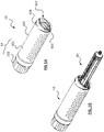
- FIGs. 1A, 1B , 2 and 3 illustrate an apparatus 10 for delivering fluid from a fluid container according to one embodiment.
- Apparatus 10 has a housing 13, a slider 210 movably disposed in housing 13 and a resilient member 215 connected between the housing 13 and the slider 210.
- housing 13 includes a hollow mandrel 101 and a sleeve 301 movably coupled to hollow mandrel 101, and slider 210 is movably disposed in the hollow mandrel 101.
- Sleeve 301 has an entrance 307 formed at one end. Entrance 307 includes a rim 308 extending radially and inwardly from side wall 306 of sleeve 301, and an opening 309 surrounded by rim 308.
- the resilient member is a thin, flat shaped tape spring 215 made of elastically deformable material, e.g. metal, and coiled to form a reel as shown in Figs. 2 , 3 , 4A and 4B .
- Spring 215 has a first end 217 at the outer end of the reel, and a second end 212 at the inner end of the reel.
- Spring 215 is wound around an axle 216 at the second end 212, and the axle 216 is attached to the slider 210.
- a hollow core 218 may be used to support spring 215 and coupled to axle 216 via a bearing 219.
- the first end 217 extends out of the slider 210 and is connected to the housing 13 i.e. in the present embodiment, the first end 217 is connected to the hollow mandrel 101.
- the spring 215 is at the original, un-deformed state when coiled and with a major portion of the spring 215 received in the slider 210, as shown in Figs. 4A and 4B .
- the slider 210 moves relative to the hollow mandrel 101 away from the entrance 307, causing the spring 215 to be pulled out and uncoil from the slider 210 and stores a potential energy in the spring 215, as shown in Fig. 5 .
- the potential energy will generate a driving force required to push fluid out of a fluid container, such as a syringe, attached to the apparatus 10.
- the displacement of the slider 210 in the hollow mandrel 101 is constrained by guide channels 203 and 204 that could be made from separately formed parts installed within the inner walls of the hollow mandrel 101, or the guide channels 203 and 204 could be integrated to the hollow mandrel 101 itself.
- the guide channels 203, 204 assist in aligning the direction of the displacement of the slider 210 to be in a generally parallel direction as the axis of the plunger movement within the fluid container.
- the choice of the number of springs or its dimensions i.e. width, outer diameter, thickness and spring material determines the force that is desired.
- the axle 216 may be configured to be free to rotate relative to the slider 210, to ease the spring 215 coiling and uncoiling about the axel 216.
- axle 216 may be fixed to slider 210 while the second end 212 of the spring 215 is rotatably attached around the axle 216 to maintain connection between the slider 210 and the spring 215 during coiling and uncoiling of the spring 215 around the axel 216.
- the constraints in the volume space of the hollow mandrel 101 corresponds to the use of a single spring, in order to provide a desired force for expelling fluid from a fluid container attached to the apparatus 10.
- the spring set could be a single spring or multiple springs arranged in appropriate configurations to provide desired force.
- multiple springs could be arranged within a common axis or with their axes along the lateral direction in which they are displaced when the apparatus is in use.
- the mandrel 101 shown in Figs. 4A and 4B is at fully extending position out of the sleeve 301.
- the slider 210 is disposed in mandrel 101 and movable relative to mandrel 101 long the channels 203 and 204.
- the spring 215 is coiled, a majority portion of spring 215 is wound around axle 216 and received in the slider 210, while the slider 210 is located generally at the first position, adjacent to the entrance / open end 307 / 309 of the sleeve 301 as shown in Fig. 4A .
- an external force F1 is applied to slider 210 along direction 12 i.e. away from entrance 307, the slider 210 will be pushed away from entrance 307, as shown in Fig. 5 .
- the sleeve 301 has helical thread grooves 305 formed on its inner sidewall. Screw threads 105 of corresponding dimension and pitch are formed on the outer surface of the hollow mandrel 101. Engagement of the thread grooves 305 and screw threads 105 will allow rotation of the hollow mandrel 101 relative to the telescopic sleeve 301 and by such rotation, the hollow mandrel 101 will be moved relative to the sleeve 301 along axial direction 14.
- the screw threads 105 could be a single loop or multiple loops around the outer circumference of the hollow mandrel 101.
- a syringe 40 is firstly filled with a desired amount of liquid medicine 401 in the barrel 406.
- a tubing 415 connected to the nozzle 408 is then shut off, by a valve or clip 417 attached on tubing 415 to seal the liquid medicine 401 in the syringe 40.
- the plunger 402 is prevented from moving relative to barrel 406.
- a seat 211 is attached to the slider 210, and is rotatable relative to slider 210.
- the advantages of seat 211 is to reduce torsional forces acting on the plunger 402 by the slider 210, when the mandrel 101 is rotated into the telescopic sleeve 301.
- the slider 210 may also be directly engaged to the plunger, without the presence of seat 211.
- the plunger 402 is then inserted through entrance 307 of sleeve 301, into hollow mandrel 101 ( Figs. 6 and 7(A) ).
- the barrel 406 of syringe 40 is twisted, by 90 degree for example, so that the oval-shaped flange 403 and similarly oval-shaped opening 309 are positioned with the longer axis of the flange 403 and the longer axis of the opening 309 aligned perpendicular to each other, to lock the barrel 406 to the sleeve 301.
- Other forms and means of affixing the syringe of other configurations may be adopted which should not be considered to be excluded from the scope as defined by the claims appended thererafter.
- the mandrel 101 is rotated to move into the sleeve 301, to bring the seat 211 of slider 210 into engagement with the plunger 402.
- the barrel 406 and plunger 402 are both relatively stationary with respect to the sleeve 301 since the valve or clip 417 is closed, further advancement of the mandrel 101 into the sleeve 301 will cause the slider 210 to move towards the closed end 103 of the mandrel 101, resulting in the spring 215 being uncoiled and pulled out of the slider 210, as shown in Fig. 7(D) .
- the slider 210 could be affixed with a magnetic sensor 252 that is in communication with a reader, e.g. a magnetic linear strip 254 attached on the adjacent channel 203 and/or 204 of housing 13. Interaction of the sensor 252 and strip 254 could detect the position of the slider 210 relative to the mandrel 101, which may be displayed on a screen 256 integrated on the apparatus 10 or onto a separate display 257 in signal communication with the sensor 252.
- a reader e.g. a magnetic linear strip 254 attached on the adjacent channel 203 and/or 204 of housing 13.
- Interaction of the sensor 252 and strip 254 could detect the position of the slider 210 relative to the mandrel 101, which may be displayed on a screen 256 integrated on the apparatus 10 or onto a separate display 257 in signal communication with the sensor 252.
- projections or stubs 221, 222, 223 and 224 may be formed at the corners of the slider 210 to create a clearance or gap 226 between the main body portion 210a of the slider 210 and the channels 203, 204 that allows displacement sensors 252 to be installed.
- the communication between the displacement sensor 252 and the display screen 256 or 257 can be established by Bluetooth, WiFi or direct cable connections.
- a skilled person in the art should be able to extrapolate the data on position and or displacement of the slider 210 relative to the channel 203/204 to obtain valuable information like flow rate at which the fluid is expelled, volume expelled and volume remaining in the syringe. With a built in data base of drug dose limits, commonly known as drug library, the aforesaid data could be used to provide alarms for patient risk situations related to overdose or under dose.
- Apparatus 10 may include a coupling element 209 positioned and connected between the slider 210 and the seat 211.
- Coupling element 209 is configured to cause the first end 217 of spring 215 to be positioned at a distance away from the initial unstressed position of the spring 215 within the hollow mandrel 101, such that the total distance the axis of the springs travelled is longer than the displacement required for the plunger 402 to fully discharge the fluid from the syringe.
- the length of the coupling element 209 is configured to be sufficient to cause the spring 215 to be uncoiled from the slider 210 so that the driving force F2 exerted on the plunger 402 would have already reached its constant level when fluid start to flow.
- this deflected length is about 1 to 1.5 times of the outer diameter of the spring 215 in coiled form.
- the coupling element 209 assists in generating a relatively more constant driving force acting on the fluid through the plunger, resulting in a relatively more constant flow profile during the fluid delivery, as shown in Fig. 13 .
- Fig. 12 shows a system 80 for fluid delivery.
- the system 80 includes an array of docking stations 50 each being connected to a display unit 60 that is connected to a controller 70 via a direct or wireless communication network and power supply cable, for use in e.g. a patient centre for automated medication service.
- Each docking station 50 is configured to detachably hold an apparatus 10 and a syringe 40 attached to the apparatus 10 in a manner as illustrated above.
- system 80 may be set up at a medical center or any suitable location for providing medication administration to patients.
- a system 82 for fluid delivery includes one or more apparatus 10 as illustrated above, and a mobile platform 822 connected to each of the apparatus 10 with sensors and stripes installed thereon. Displacement of the slider in each apparatus and flow rate data can be communicated to the mobile platform via wireless network protocols such as Bluetooth, WiFi and/or GSM, which are monitored and controlled for to increase the applicability of the apparatus for medicament delivery to patients.
- wireless network protocols such as Bluetooth, WiFi and/or GSM
Landscapes
- Health & Medical Sciences (AREA)
- Heart & Thoracic Surgery (AREA)
- Animal Behavior & Ethology (AREA)
- General Health & Medical Sciences (AREA)
- Biomedical Technology (AREA)
- Engineering & Computer Science (AREA)
- Hematology (AREA)
- Life Sciences & Earth Sciences (AREA)
- Veterinary Medicine (AREA)
- Anesthesiology (AREA)
- Public Health (AREA)
- Vascular Medicine (AREA)
- Pulmonology (AREA)
- Physics & Mathematics (AREA)
- Fluid Mechanics (AREA)
- Infusion, Injection, And Reservoir Apparatuses (AREA)
Abstract
Description
- This claims priority to
Singapore Patent Application Serial No. 10201604323Y filed May 30, 2016 - The present disclosure relates to an apparatus and system for delivering fluid from a fluid container. In particular, it relates to an apparatus and system for infusion and injection of fluid medical substance.
- The use of ambulatory, mechanically driven infusion devices or pumps have gain wide acceptance due to its ease of use, safe and effective means of drug delivery in both hospital and non-hospital based settings. The salient benefits are derived from the absence of programming or infusion settings, unlike electronic pumps which can lead to serious adverse events arising from human errors.
- The general principle of such mechanical pumps is based on a force or pressure action on a body of fluid within an enclosed container or receptacle such that the fluid is pushed out through a flow restrictor connected to the fluid container. For any given pressure acting on the fluid, the flow rate achieved is determined by the internal diameter of the lumen of the restrictor based on Bernoulli's and/or Hagen principle.
- Albeit the safety element imbued in mechanical pumps, there are limitations that relates to flow accuracy and costs, particularly when the pump is intended for single use only. The flow rate accuracy which is typically designed to meet prevalent international standards of +/- 15% limits the device to its use with only drugs that allow greater tolerant ranges. There are also other issues pertaining to storage and operational use, for example if the device is constructed with elastomeric membranes as reservoir, the pressure generated would be affected by the time duration and conditions of storage.
- In one embodiment, a reusable spring driven apparatus that enables fluid delivery including the infusion of medication at an accurate and uniform flow rate is disclosed.
- The disclosed embodiments can employ the use of a constant force tape spring to produce a significantly uniform force that acts on a body of fluid filled in a generally tubular container such as a syringe. In one embodiment, a syringe has a rigid cylindrical barrel that is open on the back end and a plunger or a piston like contraption is axially movable within the container through the back end. The front end of the barrel has a tip or nozzle that lends itself to fluid communication with the outlet of a tube along which a flow restriction element such as a valve or a clip is provided, either by its internal diameter or a purposely designed capillary in its path. When the plunger, which includes a fluid sealing feature, is pushed towards the nozzle, the fluid contents e.g. liquid medicine inside the barrel would be discharged via the nozzle.
- The apparatus that drives the plunger includes a resilient member, e.g. a constant force spring of a thin, flat tape shape connected to a slider which is movably disposed in a housing. The spring has a first end protruding out of the slider and connected to the housing, and a second end connected to the slider. When no external force is applied, the spring is coiled about the second end, with a major portion of the spring wounded and received in the slider. When an external force is applied to the slider, as the first end of the spring is connected to the housing, the slider is moved relative the housing in a direction away from the first end, to create the required linear displacement that uncoils the spring out of the slider to store a potential energy in the spring. A syringe can be attached to the housing, with the plunger abutting against the slider. The slider counteracts against the plunger to exert a driving force to the plunger. When the valve or clip connected to the nozzle of the syringe is opened, the potential energy stored in the spring is allowed to release, such that the driving force presses against the plunger in pushing the fluid out of the syringe, to deliver the fluid to a user e.g. a patient to whom the syringe is connected.
- In one embodiment, an apparatus is configured to support syringes filled with any volume of liquid medicine up to the maximum capacity that is specified for a particular model of a syringe. This feature provides less limitations to the selection and use of the syringes as the volume of medication needs no longer be restricted to any specified volume of liquid medicine filled in the syringe.
- In one embodiment, the housing includes a hollow mandrel in which the slider is movably disposed, and a sleeve telescopically coupled to an external side surface of the mandrel, through helical thread grooves formed on the inner surface of the sleeve and corresponding helical thread ridges formed on the external surface of the hollow mandrel. When an external force is applied against the slider, by e.g. the engagement of the plunger of a syringe attached to the sleeve, rotating the hollow mandrel relative to the sleeve will displace the slider and the coiled section of the spring away from the first end of the spring, relative to the hollow mandrel. The displacement maybe equivalent to the length the plunger needed to travel with respect to the syringe barrel, in order to push the fluid out from the syringe.
- The slider maybe pushed away from the first end with a distance longer than the plunger travel distance, to reserve in the spring a residual or pre-stressed force for acting on the plunger via the slider. This pre-stressed force is advantageous to provide a relatively more constant force against the plunger until the volume of the fluid filled in the syringe is completely dispensed, to ensure the liquid medicine delivery in a relatively more constant flow rate.
- In addition to the practical benefits described above, embodiments described herein provide a technological advantage whereby moving a coiled section of the spring is relatively easier to achieve and control, for example via an axle mechanism coupled to the slider that moves along a track guide in the hollow mandrel.
- Another additional advantage is the use of a coupling element on the slider for engaging a syringe plunger in creating a pre-stress force in the spring. The aforesaid coupling element enables the use of the approximate constant range of the force profile in driving the plunger of a syringe, for fluid delivery under a relatively more constant flow rate. The result of achieving a relatively more constant force profile throughout the displaced distance of the plunger enables the syringe to be filled with varying volume of fluid without affecting the intended flow rate of fluid delivery.
- A further aspect of the present disclosure is the use of hollow mandrel and telescopic sleeve to support syringes filled with different volume of liquid medicine. In one embodiment, the slider is movably disposed in the hollow mandrel and the syringe is attached to the sleeve. When the hollow mandrel is rotated relative to the sleeve by means of the screw threads engagement, surface overlaps between the sleeve and the hollow mandrel can be progressively adjusted and set at any position relative to each other to adapt to syringes of plungers extended in different lengths. The uncoiling of the coiled section of the spring is due to the action of the plunger and coupling on the slider when the hollow mandrel and the sleeve overlaps incrementally. The combined effect is to displace the coiled section of the spring and the slider away from the first end of the spring which is affixed to the hollow mandrel, causing uncoiling and extension of the spring and storing potential energy in the spring.
- In another embodiment, uncoiling of the spring can also be achieved by directly sliding the hollow mandrel into the sleeve element to cause more overlapping surface areas between the sleeve and the hollow mandrel, although the force required in this method is appreciably higher compared to a rotational movement of the sleeve relative to the housing.
-
-
Fig. 1A is a perspective view of an apparatus for delivering fluid according to one embodiment; -
Fig. 1B is a perspective view showing the apparatus ofFig. 1A to which a fluid container is attached for fluid delivery; -
Fig. 2 is an exploded perspective view ofFig. 1A ; -
Fig. 3 is a partial enlarged view ofportion 3 ofFig. 2 ; -
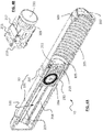
Fig. 4A is a cross sectional perspective view ofFig. 1A showing the slider at the first position adjacent to the entrance of the sleeve; -
Fig. 4B is a perspective view showing the position of the slider of the apparatus shown inFig. 4A ; -
Fig. 5 is a cross sectional perspective view ofFig. 1A showing the slider at the second position; -
Fig. 6 is a cross sectional perspective view of the apparatus ofFig. 1A to which a filled fluid container is to be attached; -
Figs. 7(A), 7(B), 7(C) and 7(D) are cross sectional perspective views showing a method of attaching a fluid container to the apparatus ofFig. 1 ; -
Fig. 8A is a cross sectional perspective view of the apparatus ofFig. 1A to which a fluid container is attached and ready for delivering fluid from the fluid container; -
Fig. 8B is a perspective view showing the slider of the apparatus shown inFig. 8A ; -
Fig. 9 is a cross sectional perspective view of the apparatus ofFig. 1A to which a fluid container is attached, after completion of the fluid delivery; -
Fig. 10 is a perspective view of the slider and spring assembly of the apparatus shown inFig. 2 ; -
Fig. 11 is a side view ofFig. 10 ; -
Fig. 12 is a diagram showing a system for fluid delivery according to an embodiment; -
Fig. 13 is a chart showing a flow profile of an apparatus ofFig. 1A used to deliver fluid from a fluid container attached to the apparatus; -
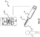
Fig. 14 is a diagram showing mobile connectivity of an apparatus ofFig. 1 . - Examples of embodiments will be shown to provide an understanding of the principles of the design features, its function, manufacture, use of the device and methods disclosed. The embodiments shown are intended to be exemplary and non-limiting. The features described in the embodiment may be combined with variants or modifications of other embodiments to achieve the goals of a device with the features and novelties described. Such variants or modifications are intended to be within the scope of the present disclosure.
- By way of a non-limiting example,
Figs. 1A, 1B ,2 and3 illustrate anapparatus 10 for delivering fluid from a fluid container according to one embodiment.Apparatus 10 has ahousing 13, aslider 210 movably disposed inhousing 13 and aresilient member 215 connected between thehousing 13 and theslider 210. In the present embodiment,housing 13 includes ahollow mandrel 101 and asleeve 301 movably coupled tohollow mandrel 101, andslider 210 is movably disposed in thehollow mandrel 101.Sleeve 301 has anentrance 307 formed at one end.Entrance 307 includes arim 308 extending radially and inwardly fromside wall 306 ofsleeve 301, and anopening 309 surrounded byrim 308. - The resilient member is a thin, flat shaped
tape spring 215 made of elastically deformable material, e.g. metal, and coiled to form a reel as shown inFigs. 2 ,3 ,4A and 4B .Spring 215 has afirst end 217 at the outer end of the reel, and asecond end 212 at the inner end of the reel.Spring 215 is wound around anaxle 216 at thesecond end 212, and theaxle 216 is attached to theslider 210. Ahollow core 218 may be used to supportspring 215 and coupled toaxle 216 via abearing 219. Thefirst end 217 extends out of theslider 210 and is connected to thehousing 13 i.e. in the present embodiment, thefirst end 217 is connected to thehollow mandrel 101. - The
spring 215 is at the original, un-deformed state when coiled and with a major portion of thespring 215 received in theslider 210, as shown inFigs. 4A and 4B . Upon receiving an external force F1, theslider 210 moves relative to thehollow mandrel 101 away from theentrance 307, causing thespring 215 to be pulled out and uncoil from theslider 210 and stores a potential energy in thespring 215, as shown inFig. 5 . The potential energy will generate a driving force required to push fluid out of a fluid container, such as a syringe, attached to theapparatus 10. The displacement of theslider 210 in thehollow mandrel 101 is constrained byguide channels hollow mandrel 101, or theguide channels hollow mandrel 101 itself. Theguide channels slider 210 to be in a generally parallel direction as the axis of the plunger movement within the fluid container. The choice of the number of springs or its dimensions i.e. width, outer diameter, thickness and spring material determines the force that is desired. - The
axle 216 may be configured to be free to rotate relative to theslider 210, to ease thespring 215 coiling and uncoiling about theaxel 216. Alternatively,axle 216 may be fixed toslider 210 while thesecond end 212 of thespring 215 is rotatably attached around theaxle 216 to maintain connection between theslider 210 and thespring 215 during coiling and uncoiling of thespring 215 around theaxel 216. - In this embodiment, the constraints in the volume space of the
hollow mandrel 101 corresponds to the use of a single spring, in order to provide a desired force for expelling fluid from a fluid container attached to theapparatus 10. In other embodiments, the spring set could be a single spring or multiple springs arranged in appropriate configurations to provide desired force. By way of example, multiple springs could be arranged within a common axis or with their axes along the lateral direction in which they are displaced when the apparatus is in use. - The
mandrel 101 shown inFigs. 4A and 4B is at fully extending position out of thesleeve 301. Theslider 210 is disposed inmandrel 101 and movable relative to mandrel 101 long thechannels spring 215 is coiled, a majority portion ofspring 215 is wound aroundaxle 216 and received in theslider 210, while theslider 210 is located generally at the first position, adjacent to the entrance /open end 307 / 309 of thesleeve 301 as shown inFig. 4A . When an external force F1 is applied toslider 210 alongdirection 12 i.e. away fromentrance 307, theslider 210 will be pushed away fromentrance 307, as shown inFig. 5 . - The
sleeve 301 hashelical thread grooves 305 formed on its inner sidewall.Screw threads 105 of corresponding dimension and pitch are formed on the outer surface of thehollow mandrel 101. Engagement of thethread grooves 305 andscrew threads 105 will allow rotation of thehollow mandrel 101 relative to thetelescopic sleeve 301 and by such rotation, thehollow mandrel 101 will be moved relative to thesleeve 301 alongaxial direction 14. Thescrew threads 105 could be a single loop or multiple loops around the outer circumference of thehollow mandrel 101. - As shown in
Figs. 6 and7(A) to 7(D) , in use, asyringe 40 is firstly filled with a desired amount ofliquid medicine 401 in thebarrel 406. Atubing 415 connected to thenozzle 408 is then shut off, by a valve orclip 417 attached ontubing 415 to seal theliquid medicine 401 in thesyringe 40. As such, theplunger 402 is prevented from moving relative tobarrel 406. - In this embodiment, a
seat 211 is attached to theslider 210, and is rotatable relative toslider 210. The advantages ofseat 211 is to reduce torsional forces acting on theplunger 402 by theslider 210, when themandrel 101 is rotated into thetelescopic sleeve 301. However, theslider 210 may also be directly engaged to the plunger, without the presence ofseat 211. - The
plunger 402 is then inserted throughentrance 307 ofsleeve 301, into hollow mandrel 101 (Figs. 6 and7(A) ). After theplunger 402 andflange 403 pass through theentrance 307, thebarrel 406 ofsyringe 40 is twisted, by 90 degree for example, so that the oval-shapedflange 403 and similarly oval-shapedopening 309 are positioned with the longer axis of theflange 403 and the longer axis of theopening 309 aligned perpendicular to each other, to lock thebarrel 406 to thesleeve 301. Other forms and means of affixing the syringe of other configurations may be adopted which should not be considered to be excluded from the scope as defined by the claims appended thererafter. - Once the
barrel 406 is fixed to thesleeve 301, as shown inFig. 7(B), 7(C) and 7(D) , themandrel 101 is rotated to move into thesleeve 301, to bring theseat 211 ofslider 210 into engagement with theplunger 402. As thebarrel 406 andplunger 402 are both relatively stationary with respect to thesleeve 301 since the valve orclip 417 is closed, further advancement of themandrel 101 into thesleeve 301 will cause theslider 210 to move towards theclosed end 103 of themandrel 101, resulting in thespring 215 being uncoiled and pulled out of theslider 210, as shown inFig. 7(D) . - With the
spring 215 uncoiled, there stores a potential energy in thespring 215 which generates a driving force F2 acting against theplunger 402, as shown inFig. 8A . Theapparatus 10 is now ready for delivering the fluid i.e. liquid medicine from thesyringe 40 attached to theapparatus 10. A shown inFig. 9 , when the valve orclip 417 is opened, driving force F2 will prevail and can be released, which pushes theplunger 402 to move into thebarrel 406 ofsyringe 40, to expel theliquid medicine 401 out of thesyringe 40 throughnozzle 408, to complete the fluid delivery. Throughout the whole process of fluid delivery, the driving force F2 is maintained at a substantial constant value, which enables the fluid to be delivered under a contact flow rate. - The
slider 210 could be affixed with amagnetic sensor 252 that is in communication with a reader, e.g. a magneticlinear strip 254 attached on theadjacent channel 203 and/or 204 ofhousing 13. Interaction of thesensor 252 andstrip 254 could detect the position of theslider 210 relative to themandrel 101, which may be displayed on ascreen 256 integrated on theapparatus 10 or onto aseparate display 257 in signal communication with thesensor 252. - A shown in
Figs. 10 and 11 , projections orstubs slider 210 to create a clearance orgap 226 between themain body portion 210a of theslider 210 and thechannels displacement sensors 252 to be installed. The communication between thedisplacement sensor 252 and thedisplay screen slider 210 relative to thechannel 203/204 to obtain valuable information like flow rate at which the fluid is expelled, volume expelled and volume remaining in the syringe. With a built in data base of drug dose limits, commonly known as drug library, the aforesaid data could be used to provide alarms for patient risk situations related to overdose or under dose. -
Apparatus 10 may include acoupling element 209 positioned and connected between theslider 210 and theseat 211. Couplingelement 209 is configured to cause thefirst end 217 ofspring 215 to be positioned at a distance away from the initial unstressed position of thespring 215 within thehollow mandrel 101, such that the total distance the axis of the springs travelled is longer than the displacement required for theplunger 402 to fully discharge the fluid from the syringe. In principle, the length of thecoupling element 209 is configured to be sufficient to cause thespring 215 to be uncoiled from theslider 210 so that the driving force F2 exerted on theplunger 402 would have already reached its constant level when fluid start to flow. Typically this deflected length is about 1 to 1.5 times of the outer diameter of thespring 215 in coiled form. Thecoupling element 209 assists in generating a relatively more constant driving force acting on the fluid through the plunger, resulting in a relatively more constant flow profile during the fluid delivery, as shown inFig. 13 . -
Fig. 12 shows asystem 80 for fluid delivery. Thesystem 80 includes an array ofdocking stations 50 each being connected to adisplay unit 60 that is connected to acontroller 70 via a direct or wireless communication network and power supply cable, for use in e.g. a patient centre for automated medication service. Eachdocking station 50 is configured to detachably hold anapparatus 10 and asyringe 40 attached to theapparatus 10 in a manner as illustrated above. In use,system 80 may be set up at a medical center or any suitable location for providing medication administration to patients. - As shown in
Fig. 14 , asystem 82 for fluid delivery includes one ormore apparatus 10 as illustrated above, and amobile platform 822 connected to each of theapparatus 10 with sensors and stripes installed thereon. Displacement of the slider in each apparatus and flow rate data can be communicated to the mobile platform via wireless network protocols such as Bluetooth, WiFi and/or GSM, which are monitored and controlled for to increase the applicability of the apparatus for medicament delivery to patients.
Claims (15)
- An apparatus comprising:a housing;a slider movably disposed in the housing;a resilient member having a first end connected to the housing and a second end connected to the slider,wherein upon receiving an external force, the slider moves relative to the housing to deform the resilient member from a coiled state toward an uncoiled state, and upon release of the external force, the resilient member is allowed to resume to the coiled state for urging the slider against a fluid container attached to the housing to deliver fluid from the fluid container.
- The apparatus as recited in claim 1, wherein the housing includes a mandrel and a sleeve movably coupled to an external surface of the mandrel, the first end of the resilient member is connected to the mandrel and the slider is movably disposed in the mandrel.
- The apparatus as recited in claim 2, wherein the sleeve is threadedly coupled to the mandrel such that rotation of the mandrel relative to the sleeve about a longitudinal axis moves the mandrel along the longitudinal axis relative to the sleeve.
- The apparatus as recited in claim 3, wherein upon a fluid container being attached to the sleeve, the fluid container abuts against the slider to move the slider relative to the mandrel during movement of the mandrel into the sleeve.
- The apparatus as recited in claim 2, wherein the sleeve has an entrance formed at one end thereof, wherein the entrance is to allow a fluid container to be placed therethrough to attach the fluid container to the sleeve.
- The apparatus as recited in claim 5, wherein upon receiving the external force, the slider moves relative to the mandrel from a first position adjacent to the entrance toward a second position away from the entrance to elastically deform the resilient member from the coiled state to the uncoiled state, and upon release of the external force, the resilient member is allowed to resume to the coiled state to move the slider toward the first position for urging the slider against the fluid container to deliver fluid from the fluid container.
- The apparatus as recited in claim 1, further comprising a seat member rotatably attached to the slider, wherein the seat member is to abut against the fluid container after the fluid container is attached to the housing.
- The apparatus as recited in claim 7, further comprising an extension coupling positioned between the slider and the seat member, wherein the extension coupling is to create a preload on the resilient member when the slider is at the first position.
- The apparatus as recited in claim 1, further comprising a sensor attached to the slider and a reader attached to the housing, wherein the sensor and the reader are to detect a positional relationship between the slider and the housing.
- The apparatus as recited in claim 9, further comprising a screen coupled to the reader for displaying information related to the positional relationship.
- The apparatus as recited in claim 10, wherein the slider further comprising one or more stubs projecting from a body portion thereof to form a clearance between the body portion and the housing, wherein the sensor is positioned in the clearance.
- An apparatus for delivering fluid, the apparatus comprising:a sleeve to which a fluid container is attachable;a mandrel movably coupled to and positioned in the sleeve;a slider movably disposed in the mandrel;a resilient member connecting the slider to the mandrel,wherein upon receiving an external force, the slider moves from a first position toward a second position to uncoil the resilient member, and upon release of the external force, the resilient member is allowed to coil to urge the slider against the fluid container to deliver fluid from the fluid container.
- A system for delivering fluid, the system comprising:a syringe having a barrel, a plunger movably coupled to the barrel and a nozzle in fluid communication with the barrel;an apparatus attached to the syringe, the apparatus comprising:a housing to which the barrel is attached;a slider movably disposed in the housing and abuts against the plunger;a resilient member having a first end connected to the housing and a second end connected to the slider,wherein upon the nozzle being closed, the resilient member is elastically deformed from an original state, and upon the nozzle being opened, the resilient member is allowed to resume to the original state to urge the slider against the plunger to deliver fluid from the syringe.
- The system as recited in claim 13, further comprising a docking station to which the apparatus is detachably supported.
- The system as recited in claim 14, further comprising a controller coupled to the docking station and the apparatus, and a screen coupled to the controller for displaying status of the system during fluid delivery.
Applications Claiming Priority (1)
| Application Number | Priority Date | Filing Date | Title |
|---|---|---|---|
| SG10201604323YA SG10201604323YA (en) | 2016-05-30 | 2016-05-30 | Spring driven fluid delivery apparatus |
Publications (2)
| Publication Number | Publication Date |
|---|---|
| EP3281659A1 true EP3281659A1 (en) | 2018-02-14 |
| EP3281659B1 EP3281659B1 (en) | 2022-02-23 |
Family
ID=60420298
Family Applications (1)
| Application Number | Title | Priority Date | Filing Date |
|---|---|---|---|
| EP17173314.0A Not-in-force EP3281659B1 (en) | 2016-05-30 | 2017-05-29 | Apparatus and system for fluid delivery |
Country Status (5)
| Country | Link |
|---|---|
| US (1) | US10610641B2 (en) |
| EP (1) | EP3281659B1 (en) |
| CN (1) | CN107441595B (en) |
| ES (1) | ES2913656T3 (en) |
| SG (1) | SG10201604323YA (en) |
Cited By (1)
| Publication number | Priority date | Publication date | Assignee | Title |
|---|---|---|---|---|
| EP3338830A1 (en) * | 2016-12-22 | 2018-06-27 | Epic Medical Pte Ltd | Syringe driving apparatus |
Families Citing this family (2)
| Publication number | Priority date | Publication date | Assignee | Title |
|---|---|---|---|---|
| CN116669791A (en) * | 2020-12-31 | 2023-08-29 | 里珍纳龙药品有限公司 | Autoinjectors and related methods of use |
| USD1042806S1 (en) * | 2022-12-22 | 2024-09-17 | Halozyme, Inc. | Injection device |
Citations (7)
| Publication number | Priority date | Publication date | Assignee | Title |
|---|---|---|---|---|
| US4059110A (en) * | 1976-10-07 | 1977-11-22 | Timex Corporation | Clockwork driven hypodermic syringe |
| US4755172A (en) * | 1987-06-30 | 1988-07-05 | Baldwin Brian E | Syringe holder/driver and syringe arrangement and syringe/holder driver therefor |
| EP0824923A1 (en) * | 1996-08-23 | 1998-02-25 | Becton Dickinson France S.A. | Cartrigde with temporarily lockable cap for an injection device |
| EP1728529A1 (en) * | 2005-06-01 | 2006-12-06 | SHL Medical AB | Device for delivering medicament |
| WO2014170267A1 (en) * | 2013-04-19 | 2014-10-23 | Novo Nordisk A/S | Drug delivery device with compact power unit |
| GB2534599A (en) * | 2015-01-29 | 2016-08-03 | Owen Mumford Ltd | A medicament delivery device |
| WO2017080814A1 (en) * | 2015-11-13 | 2017-05-18 | Carebay Europe Ltd | Activation mechanism for a medicament delivery device and a medicament delivery device comprising the activation mechanism |
Family Cites Families (5)
| Publication number | Priority date | Publication date | Assignee | Title |
|---|---|---|---|---|
| US4863429A (en) * | 1987-06-30 | 1989-09-05 | Baldwin Brian E | Syringe driver/syringe/tube connecting set fluid delivery arrangement, and tube connecting sets therefor |
| US5800405A (en) * | 1995-12-01 | 1998-09-01 | I-Flow Corporation | Syringe actuation device |
| US10971260B2 (en) * | 2014-09-14 | 2021-04-06 | Becton, Dickinson And Company | System and method for capturing dose information |
| US10704944B2 (en) * | 2014-09-14 | 2020-07-07 | Becton, Dickinson And Company | System and method for capturing dose information |
| SG11201702061QA (en) * | 2014-09-17 | 2017-04-27 | Palmaya Pty Ltd | Syringe infusion devices and systems for delivery of active agents |
-
2016
- 2016-05-30 SG SG10201604323YA patent/SG10201604323YA/en unknown
-
2017
- 2017-05-25 CN CN201710380506.3A patent/CN107441595B/en not_active Expired - Fee Related
- 2017-05-26 US US15/607,018 patent/US10610641B2/en active Active
- 2017-05-29 ES ES17173314T patent/ES2913656T3/en active Active
- 2017-05-29 EP EP17173314.0A patent/EP3281659B1/en not_active Not-in-force
Patent Citations (7)
| Publication number | Priority date | Publication date | Assignee | Title |
|---|---|---|---|---|
| US4059110A (en) * | 1976-10-07 | 1977-11-22 | Timex Corporation | Clockwork driven hypodermic syringe |
| US4755172A (en) * | 1987-06-30 | 1988-07-05 | Baldwin Brian E | Syringe holder/driver and syringe arrangement and syringe/holder driver therefor |
| EP0824923A1 (en) * | 1996-08-23 | 1998-02-25 | Becton Dickinson France S.A. | Cartrigde with temporarily lockable cap for an injection device |
| EP1728529A1 (en) * | 2005-06-01 | 2006-12-06 | SHL Medical AB | Device for delivering medicament |
| WO2014170267A1 (en) * | 2013-04-19 | 2014-10-23 | Novo Nordisk A/S | Drug delivery device with compact power unit |
| GB2534599A (en) * | 2015-01-29 | 2016-08-03 | Owen Mumford Ltd | A medicament delivery device |
| WO2017080814A1 (en) * | 2015-11-13 | 2017-05-18 | Carebay Europe Ltd | Activation mechanism for a medicament delivery device and a medicament delivery device comprising the activation mechanism |
Cited By (2)
| Publication number | Priority date | Publication date | Assignee | Title |
|---|---|---|---|---|
| EP3338830A1 (en) * | 2016-12-22 | 2018-06-27 | Epic Medical Pte Ltd | Syringe driving apparatus |
| US10946146B2 (en) | 2016-12-22 | 2021-03-16 | Epic Medical Pte. Ltd. | Syringe driving apparatus and system |
Also Published As
| Publication number | Publication date |
|---|---|
| US20170340820A1 (en) | 2017-11-30 |
| CN107441595A (en) | 2017-12-08 |
| SG10201604323YA (en) | 2017-12-28 |
| CN107441595B (en) | 2021-08-17 |
| US10610641B2 (en) | 2020-04-07 |
| ES2913656T3 (en) | 2022-06-03 |
| EP3281659B1 (en) | 2022-02-23 |
Similar Documents
| Publication | Publication Date | Title |
|---|---|---|
| US8517991B2 (en) | Drive system for use with an insulin delivery device | |
| EP2195052B1 (en) | External drug pump | |
| CN203935494U (en) | Device for an infusion set and an infusion pump | |
| US10737038B2 (en) | Catheter insertion device and method of inserting a catheter | |
| JP6367193B2 (en) | Modular infusion pump, method for controlling the delivery of medication, infusion pump, and method for measuring the level of medication | |
| EP3281659B1 (en) | Apparatus and system for fluid delivery | |
| JP2005523127A (en) | Dispenser for twin patient infusion device | |
| JP2007528260A (en) | Lead screw driven syringe with integral separating plunger nut and system comprising the syringe | |
| JP7600146B2 (en) | Valve Assembly | |
| CN117504055A (en) | Continuous micro-dosing device and injection method | |
| CN106794311A (en) | Torque spring for injection device and the injection device including this torque spring | |
| US20230248901A1 (en) | Drive device including flexible plunger shaft | |
| WO2024211400A1 (en) | Liquid detection sensor | |
| KR20220032404A (en) | Apparatus for Infusing medical liquid | |
| US20230144155A1 (en) | Syringe with biasing member | |
| EP4727618A1 (en) | Drug delivery device | |
| CN107029317B (en) | Medicine injector | |
| AU2020282814A1 (en) | Cartridge adapter for drug delivery device | |
| HK1148233B (en) | Novel drive system for use with an insulin delivery device |
Legal Events
| Date | Code | Title | Description |
|---|---|---|---|
| PUAI | Public reference made under article 153(3) epc to a published international application that has entered the european phase |
Free format text: ORIGINAL CODE: 0009012 |
|
| STAA | Information on the status of an ep patent application or granted ep patent |
Free format text: STATUS: THE APPLICATION HAS BEEN PUBLISHED |
|
| AK | Designated contracting states |
Kind code of ref document: A1 Designated state(s): AL AT BE BG CH CY CZ DE DK EE ES FI FR GB GR HR HU IE IS IT LI LT LU LV MC MK MT NL NO PL PT RO RS SE SI SK SM TR |
|
| AX | Request for extension of the european patent |
Extension state: BA ME |
|
| STAA | Information on the status of an ep patent application or granted ep patent |
Free format text: STATUS: REQUEST FOR EXAMINATION WAS MADE |
|
| 17P | Request for examination filed |
Effective date: 20180814 |
|
| RBV | Designated contracting states (corrected) |
Designated state(s): AL AT BE BG CH CY CZ DE DK EE ES FI FR GB GR HR HU IE IS IT LI LT LU LV MC MK MT NL NO PL PT RO RS SE SI SK SM TR |
|
| STAA | Information on the status of an ep patent application or granted ep patent |
Free format text: STATUS: EXAMINATION IS IN PROGRESS |
|
| 17Q | First examination report despatched |
Effective date: 20210118 |
|
| GRAP | Despatch of communication of intention to grant a patent |
Free format text: ORIGINAL CODE: EPIDOSNIGR1 |
|
| STAA | Information on the status of an ep patent application or granted ep patent |
Free format text: STATUS: GRANT OF PATENT IS INTENDED |
|
| INTG | Intention to grant announced |
Effective date: 20210820 |
|
| GRAS | Grant fee paid |
Free format text: ORIGINAL CODE: EPIDOSNIGR3 |
|
| RAP3 | Party data changed (applicant data changed or rights of an application transferred) |
Owner name: EPIC MEDICAL PTE LTD |
|
| GRAA | (expected) grant |
Free format text: ORIGINAL CODE: 0009210 |
|
| STAA | Information on the status of an ep patent application or granted ep patent |
Free format text: STATUS: THE PATENT HAS BEEN GRANTED |
|
| AK | Designated contracting states |
Kind code of ref document: B1 Designated state(s): AL AT BE BG CH CY CZ DE DK EE ES FI FR GB GR HR HU IE IS IT LI LT LU LV MC MK MT NL NO PL PT RO RS SE SI SK SM TR |
|
| REG | Reference to a national code |
Ref country code: GB Ref legal event code: FG4D |
|
| REG | Reference to a national code |
Ref country code: CH Ref legal event code: EP |
|
| REG | Reference to a national code |
Ref country code: AT Ref legal event code: REF Ref document number: 1469948 Country of ref document: AT Kind code of ref document: T Effective date: 20220315 |
|
| REG | Reference to a national code |
Ref country code: IE Ref legal event code: FG4D |
|
| REG | Reference to a national code |
Ref country code: DE Ref legal event code: R096 Ref document number: 602017053619 Country of ref document: DE |
|
| REG | Reference to a national code |
Ref country code: ES Ref legal event code: FG2A Ref document number: 2913656 Country of ref document: ES Kind code of ref document: T3 Effective date: 20220603 |
|
| REG | Reference to a national code |
Ref country code: LT Ref legal event code: MG9D |
|
| REG | Reference to a national code |
Ref country code: NL Ref legal event code: MP Effective date: 20220223 |
|
| REG | Reference to a national code |
Ref country code: AT Ref legal event code: MK05 Ref document number: 1469948 Country of ref document: AT Kind code of ref document: T Effective date: 20220223 |
|
| PG25 | Lapsed in a contracting state [announced via postgrant information from national office to epo] |
Ref country code: SE Free format text: LAPSE BECAUSE OF FAILURE TO SUBMIT A TRANSLATION OF THE DESCRIPTION OR TO PAY THE FEE WITHIN THE PRESCRIBED TIME-LIMIT Effective date: 20220223 Ref country code: RS Free format text: LAPSE BECAUSE OF FAILURE TO SUBMIT A TRANSLATION OF THE DESCRIPTION OR TO PAY THE FEE WITHIN THE PRESCRIBED TIME-LIMIT Effective date: 20220223 Ref country code: PT Free format text: LAPSE BECAUSE OF FAILURE TO SUBMIT A TRANSLATION OF THE DESCRIPTION OR TO PAY THE FEE WITHIN THE PRESCRIBED TIME-LIMIT Effective date: 20220623 Ref country code: NO Free format text: LAPSE BECAUSE OF FAILURE TO SUBMIT A TRANSLATION OF THE DESCRIPTION OR TO PAY THE FEE WITHIN THE PRESCRIBED TIME-LIMIT Effective date: 20220523 Ref country code: NL Free format text: LAPSE BECAUSE OF FAILURE TO SUBMIT A TRANSLATION OF THE DESCRIPTION OR TO PAY THE FEE WITHIN THE PRESCRIBED TIME-LIMIT Effective date: 20220223 Ref country code: LT Free format text: LAPSE BECAUSE OF FAILURE TO SUBMIT A TRANSLATION OF THE DESCRIPTION OR TO PAY THE FEE WITHIN THE PRESCRIBED TIME-LIMIT Effective date: 20220223 Ref country code: HR Free format text: LAPSE BECAUSE OF FAILURE TO SUBMIT A TRANSLATION OF THE DESCRIPTION OR TO PAY THE FEE WITHIN THE PRESCRIBED TIME-LIMIT Effective date: 20220223 Ref country code: BG Free format text: LAPSE BECAUSE OF FAILURE TO SUBMIT A TRANSLATION OF THE DESCRIPTION OR TO PAY THE FEE WITHIN THE PRESCRIBED TIME-LIMIT Effective date: 20220523 |
|
| PGFP | Annual fee paid to national office [announced via postgrant information from national office to epo] |
Ref country code: IT Payment date: 20220531 Year of fee payment: 6 Ref country code: GB Payment date: 20220522 Year of fee payment: 6 Ref country code: FR Payment date: 20220520 Year of fee payment: 6 Ref country code: ES Payment date: 20220601 Year of fee payment: 6 Ref country code: DE Payment date: 20220602 Year of fee payment: 6 |
|
| PG25 | Lapsed in a contracting state [announced via postgrant information from national office to epo] |
Ref country code: PL Free format text: LAPSE BECAUSE OF FAILURE TO SUBMIT A TRANSLATION OF THE DESCRIPTION OR TO PAY THE FEE WITHIN THE PRESCRIBED TIME-LIMIT Effective date: 20220223 Ref country code: LV Free format text: LAPSE BECAUSE OF FAILURE TO SUBMIT A TRANSLATION OF THE DESCRIPTION OR TO PAY THE FEE WITHIN THE PRESCRIBED TIME-LIMIT Effective date: 20220223 Ref country code: GR Free format text: LAPSE BECAUSE OF FAILURE TO SUBMIT A TRANSLATION OF THE DESCRIPTION OR TO PAY THE FEE WITHIN THE PRESCRIBED TIME-LIMIT Effective date: 20220524 Ref country code: FI Free format text: LAPSE BECAUSE OF FAILURE TO SUBMIT A TRANSLATION OF THE DESCRIPTION OR TO PAY THE FEE WITHIN THE PRESCRIBED TIME-LIMIT Effective date: 20220223 Ref country code: AT Free format text: LAPSE BECAUSE OF FAILURE TO SUBMIT A TRANSLATION OF THE DESCRIPTION OR TO PAY THE FEE WITHIN THE PRESCRIBED TIME-LIMIT Effective date: 20220223 |
|
| PG25 | Lapsed in a contracting state [announced via postgrant information from national office to epo] |
Ref country code: IS Free format text: LAPSE BECAUSE OF FAILURE TO SUBMIT A TRANSLATION OF THE DESCRIPTION OR TO PAY THE FEE WITHIN THE PRESCRIBED TIME-LIMIT Effective date: 20220623 |
|
| PG25 | Lapsed in a contracting state [announced via postgrant information from national office to epo] |
Ref country code: SM Free format text: LAPSE BECAUSE OF FAILURE TO SUBMIT A TRANSLATION OF THE DESCRIPTION OR TO PAY THE FEE WITHIN THE PRESCRIBED TIME-LIMIT Effective date: 20220223 Ref country code: SK Free format text: LAPSE BECAUSE OF FAILURE TO SUBMIT A TRANSLATION OF THE DESCRIPTION OR TO PAY THE FEE WITHIN THE PRESCRIBED TIME-LIMIT Effective date: 20220223 Ref country code: RO Free format text: LAPSE BECAUSE OF FAILURE TO SUBMIT A TRANSLATION OF THE DESCRIPTION OR TO PAY THE FEE WITHIN THE PRESCRIBED TIME-LIMIT Effective date: 20220223 Ref country code: EE Free format text: LAPSE BECAUSE OF FAILURE TO SUBMIT A TRANSLATION OF THE DESCRIPTION OR TO PAY THE FEE WITHIN THE PRESCRIBED TIME-LIMIT Effective date: 20220223 Ref country code: DK Free format text: LAPSE BECAUSE OF FAILURE TO SUBMIT A TRANSLATION OF THE DESCRIPTION OR TO PAY THE FEE WITHIN THE PRESCRIBED TIME-LIMIT Effective date: 20220223 Ref country code: CZ Free format text: LAPSE BECAUSE OF FAILURE TO SUBMIT A TRANSLATION OF THE DESCRIPTION OR TO PAY THE FEE WITHIN THE PRESCRIBED TIME-LIMIT Effective date: 20220223 |
|
| REG | Reference to a national code |
Ref country code: DE Ref legal event code: R097 Ref document number: 602017053619 Country of ref document: DE |
|
| PG25 | Lapsed in a contracting state [announced via postgrant information from national office to epo] |
Ref country code: AL Free format text: LAPSE BECAUSE OF FAILURE TO SUBMIT A TRANSLATION OF THE DESCRIPTION OR TO PAY THE FEE WITHIN THE PRESCRIBED TIME-LIMIT Effective date: 20220223 |
|
| PLBE | No opposition filed within time limit |
Free format text: ORIGINAL CODE: 0009261 |
|
| REG | Reference to a national code |
Ref country code: CH Ref legal event code: PL |
|
| STAA | Information on the status of an ep patent application or granted ep patent |
Free format text: STATUS: NO OPPOSITION FILED WITHIN TIME LIMIT |
|
| REG | Reference to a national code |
Ref country code: BE Ref legal event code: MM Effective date: 20220531 |
|
| PG25 | Lapsed in a contracting state [announced via postgrant information from national office to epo] |
Ref country code: MC Free format text: LAPSE BECAUSE OF FAILURE TO SUBMIT A TRANSLATION OF THE DESCRIPTION OR TO PAY THE FEE WITHIN THE PRESCRIBED TIME-LIMIT Effective date: 20220223 Ref country code: LU Free format text: LAPSE BECAUSE OF NON-PAYMENT OF DUE FEES Effective date: 20220529 Ref country code: LI Free format text: LAPSE BECAUSE OF NON-PAYMENT OF DUE FEES Effective date: 20220531 Ref country code: CH Free format text: LAPSE BECAUSE OF NON-PAYMENT OF DUE FEES Effective date: 20220531 |
|
| 26N | No opposition filed |
Effective date: 20221124 |
|
| PG25 | Lapsed in a contracting state [announced via postgrant information from national office to epo] |
Ref country code: SI Free format text: LAPSE BECAUSE OF FAILURE TO SUBMIT A TRANSLATION OF THE DESCRIPTION OR TO PAY THE FEE WITHIN THE PRESCRIBED TIME-LIMIT Effective date: 20220223 |
|
| PG25 | Lapsed in a contracting state [announced via postgrant information from national office to epo] |
Ref country code: IE Free format text: LAPSE BECAUSE OF NON-PAYMENT OF DUE FEES Effective date: 20220529 |
|
| PG25 | Lapsed in a contracting state [announced via postgrant information from national office to epo] |
Ref country code: BE Free format text: LAPSE BECAUSE OF NON-PAYMENT OF DUE FEES Effective date: 20220531 |
|
| REG | Reference to a national code |
Ref country code: DE Ref legal event code: R119 Ref document number: 602017053619 Country of ref document: DE |
|
| GBPC | Gb: european patent ceased through non-payment of renewal fee |
Effective date: 20230529 |
|
| PG25 | Lapsed in a contracting state [announced via postgrant information from national office to epo] |
Ref country code: HU Free format text: LAPSE BECAUSE OF FAILURE TO SUBMIT A TRANSLATION OF THE DESCRIPTION OR TO PAY THE FEE WITHIN THE PRESCRIBED TIME-LIMIT; INVALID AB INITIO Effective date: 20170529 |
|
| PG25 | Lapsed in a contracting state [announced via postgrant information from national office to epo] |
Ref country code: MK Free format text: LAPSE BECAUSE OF FAILURE TO SUBMIT A TRANSLATION OF THE DESCRIPTION OR TO PAY THE FEE WITHIN THE PRESCRIBED TIME-LIMIT Effective date: 20220223 Ref country code: IT Free format text: LAPSE BECAUSE OF NON-PAYMENT OF DUE FEES Effective date: 20230529 Ref country code: DE Free format text: LAPSE BECAUSE OF NON-PAYMENT OF DUE FEES Effective date: 20231201 Ref country code: CY Free format text: LAPSE BECAUSE OF FAILURE TO SUBMIT A TRANSLATION OF THE DESCRIPTION OR TO PAY THE FEE WITHIN THE PRESCRIBED TIME-LIMIT Effective date: 20220223 Ref country code: GB Free format text: LAPSE BECAUSE OF NON-PAYMENT OF DUE FEES Effective date: 20230529 |
|
| PG25 | Lapsed in a contracting state [announced via postgrant information from national office to epo] |
Ref country code: FR Free format text: LAPSE BECAUSE OF NON-PAYMENT OF DUE FEES Effective date: 20230531 |
|
| REG | Reference to a national code |
Ref country code: ES Ref legal event code: FD2A Effective date: 20240702 |
|
| PG25 | Lapsed in a contracting state [announced via postgrant information from national office to epo] |
Ref country code: ES Free format text: LAPSE BECAUSE OF NON-PAYMENT OF DUE FEES Effective date: 20230530 |
|
| PG25 | Lapsed in a contracting state [announced via postgrant information from national office to epo] |
Ref country code: ES Free format text: LAPSE BECAUSE OF NON-PAYMENT OF DUE FEES Effective date: 20230530 |
|
| PG25 | Lapsed in a contracting state [announced via postgrant information from national office to epo] |
Ref country code: MT Free format text: LAPSE BECAUSE OF FAILURE TO SUBMIT A TRANSLATION OF THE DESCRIPTION OR TO PAY THE FEE WITHIN THE PRESCRIBED TIME-LIMIT Effective date: 20220223 |
|
| PG25 | Lapsed in a contracting state [announced via postgrant information from national office to epo] |
Ref country code: TR Free format text: LAPSE BECAUSE OF FAILURE TO SUBMIT A TRANSLATION OF THE DESCRIPTION OR TO PAY THE FEE WITHIN THE PRESCRIBED TIME-LIMIT Effective date: 20220223 |