EP3281654A1 - Peristaltikpumpe mit rotatorischem spiel - Google Patents
Peristaltikpumpe mit rotatorischem spiel Download PDFInfo
- Publication number
- EP3281654A1 EP3281654A1 EP17184562.1A EP17184562A EP3281654A1 EP 3281654 A1 EP3281654 A1 EP 3281654A1 EP 17184562 A EP17184562 A EP 17184562A EP 3281654 A1 EP3281654 A1 EP 3281654A1
- Authority
- EP
- European Patent Office
- Prior art keywords
- rotor
- peristaltic pump
- drive shaft
- rotation
- coupling structure
- Prior art date
- Legal status (The legal status is an assumption and is not a legal conclusion. Google has not performed a legal analysis and makes no representation as to the accuracy of the status listed.)
- Granted
Links
Images



Classifications
-
- A—HUMAN NECESSITIES
- A61—MEDICAL OR VETERINARY SCIENCE; HYGIENE
- A61M—DEVICES FOR INTRODUCING MEDIA INTO, OR ONTO, THE BODY; DEVICES FOR TRANSDUCING BODY MEDIA OR FOR TAKING MEDIA FROM THE BODY; DEVICES FOR PRODUCING OR ENDING SLEEP OR STUPOR
- A61M1/00—Suction or pumping devices for medical purposes; Devices for carrying-off, for treatment of, or for carrying-over, body-liquids; Drainage systems
- A61M1/14—Dialysis systems; Artificial kidneys; Blood oxygenators ; Reciprocating systems for treatment of body fluids, e.g. single needle systems for hemofiltration or pheresis
- A61M1/16—Dialysis systems; Artificial kidneys; Blood oxygenators ; Reciprocating systems for treatment of body fluids, e.g. single needle systems for hemofiltration or pheresis with membranes
- A61M1/26—Dialysis systems; Artificial kidneys; Blood oxygenators ; Reciprocating systems for treatment of body fluids, e.g. single needle systems for hemofiltration or pheresis with membranes and internal elements which are moving
- A61M1/267—Dialysis systems; Artificial kidneys; Blood oxygenators ; Reciprocating systems for treatment of body fluids, e.g. single needle systems for hemofiltration or pheresis with membranes and internal elements which are moving used for pumping
-
- A—HUMAN NECESSITIES
- A61—MEDICAL OR VETERINARY SCIENCE; HYGIENE
- A61M—DEVICES FOR INTRODUCING MEDIA INTO, OR ONTO, THE BODY; DEVICES FOR TRANSDUCING BODY MEDIA OR FOR TAKING MEDIA FROM THE BODY; DEVICES FOR PRODUCING OR ENDING SLEEP OR STUPOR
- A61M60/00—Blood pumps; Devices for mechanical circulatory actuation; Balloon pumps for circulatory assistance
- A61M60/10—Location thereof with respect to the patient's body
- A61M60/104—Extracorporeal pumps, i.e. the blood being pumped outside the patient's body
- A61M60/109—Extracorporeal pumps, i.e. the blood being pumped outside the patient's body incorporated within extracorporeal blood circuits or systems
- A61M60/113—Extracorporeal pumps, i.e. the blood being pumped outside the patient's body incorporated within extracorporeal blood circuits or systems in other functional devices, e.g. dialysers or heart-lung machines
-
- A—HUMAN NECESSITIES
- A61—MEDICAL OR VETERINARY SCIENCE; HYGIENE
- A61M—DEVICES FOR INTRODUCING MEDIA INTO, OR ONTO, THE BODY; DEVICES FOR TRANSDUCING BODY MEDIA OR FOR TAKING MEDIA FROM THE BODY; DEVICES FOR PRODUCING OR ENDING SLEEP OR STUPOR
- A61M60/00—Blood pumps; Devices for mechanical circulatory actuation; Balloon pumps for circulatory assistance
- A61M60/20—Type thereof
- A61M60/247—Positive displacement blood pumps
- A61M60/253—Positive displacement blood pumps including a displacement member directly acting on the blood
- A61M60/268—Positive displacement blood pumps including a displacement member directly acting on the blood the displacement member being flexible, e.g. membranes, diaphragms or bladders
- A61M60/279—Peristaltic pumps, e.g. roller pumps
-
- A—HUMAN NECESSITIES
- A61—MEDICAL OR VETERINARY SCIENCE; HYGIENE
- A61M—DEVICES FOR INTRODUCING MEDIA INTO, OR ONTO, THE BODY; DEVICES FOR TRANSDUCING BODY MEDIA OR FOR TAKING MEDIA FROM THE BODY; DEVICES FOR PRODUCING OR ENDING SLEEP OR STUPOR
- A61M60/00—Blood pumps; Devices for mechanical circulatory actuation; Balloon pumps for circulatory assistance
- A61M60/20—Type thereof
- A61M60/247—Positive displacement blood pumps
- A61M60/253—Positive displacement blood pumps including a displacement member directly acting on the blood
- A61M60/268—Positive displacement blood pumps including a displacement member directly acting on the blood the displacement member being flexible, e.g. membranes, diaphragms or bladders
-
- F—MECHANICAL ENGINEERING; LIGHTING; HEATING; WEAPONS; BLASTING
- F04—POSITIVE - DISPLACEMENT MACHINES FOR LIQUIDS; PUMPS FOR LIQUIDS OR ELASTIC FLUIDS
- F04B—POSITIVE-DISPLACEMENT MACHINES FOR LIQUIDS; PUMPS
- F04B43/00—Machines, pumps, or pumping installations having flexible working members
- F04B43/12—Machines, pumps, or pumping installations having flexible working members having peristaltic action
- F04B43/1253—Machines, pumps, or pumping installations having flexible working members having peristaltic action by using two or more rollers as squeezing elements, the rollers moving on an arc of a circle during squeezing
- F04B43/1276—Means for pushing the rollers against the tubular flexible member
Definitions
- the invention relates to a peristaltic pump for a device for extracorporeal blood treatment, in particular for a dialysis machine, for conveying fluid in the device, wherein the peristaltic pump has a rotatably driven with a drive shaft rotor, which cooperates with an elastically / flexibly deformable fluid conduit forming a cross-sectional constriction, wherein the cross-sectional constriction for conveying fluid is displaced (propagated) by rotation of the rotor along the fluid line and wherein the rotor is coupled to transmit torque to the drive shaft by means of a coupling structure. It further relates to a device for extracorporeal blood treatment with a peristaltic pump according to the invention, in particular a dialysis machine, with such a peristaltic pump.
- a peristaltic pump In a device for extracorporeal blood treatment, for example in a dialysis machine, a peristaltic pump has the task of defining a defined volume of a medium, such as blood or dialysis fluid, by deforming and clamping an elastically deformable fluid line from a negative pressure side (low pressure side) to a positive pressure side (High pressure side) to promote.
- a medium such as blood or dialysis fluid
- Known peristaltic pumps in such medical devices generally have a rotor, a pump housing and arranged between the rotor and the pump housing elastic hose as a fluid line.
- the rotor is torque-tight coupled to, driven by, and driven by a drive axle of the machine, and supports radially-positionable and pressure-spring-biased pressing members against the tubing and pump housings, e.g. in the form of pressure rollers.
- Such a pump are biased by the pressure rollers by means of leaf springs radially outward, for example, from US 3,737,256 known.
- the rotor is connected via a coupling mechanism with a drive axle and secured to this in the axial direction by means of a screw.
- a loosening / replacement of the rotor can be done only with the aid of a screwing and with a corresponding expenditure of time.
- a peristaltic pump for a dialysis machine in which cooperate by means of coil springs radially outwardly biased pressure rollers of a rotor with a crimping.
- the rotor has a central receiving opening for a drive shaft of a drive motor and is coupled thereto by means of a pivotable and positively connected to the drive shaft handle.
- the handle is on the one hand pivotable in a coupling position in which it cooperates positively with the drive shaft, and on the other hand in an operating position in which it is decoupled from the drive shaft and forms a kind of crank for manual operation of the rotor.
- the present invention seeks to overcome the drawbacks mentioned above, in particular a peristaltic pump for a device for extracorporeal blood treatment, in particular for a dialysis machine, to provide the higher wear resistance and a lower noise level having.
- a peristaltic pump for a device for extracorporeal blood treatment, in particular for a dialysis machine, for conveying fluid in the device wherein the peristaltic pump has a rotatably driven with a drive axle or drive shaft rotor having an elastic / flexible deformable fluid conduit forming a cross-sectional constriction cooperating, which is moved for fluid delivery by rotation of the rotor along the fluid conduit, wherein the rotor with the drive shaft or drive axle by means of a coupling structure (coupling) is coupled torque transmitting, wherein the coupling structure, the rotor and the drive shaft with a game in Rotation direction coupled to each other.
- a coupling structure coupled torque transmitting
- the object is also achieved by a device for extracorporeal blood treatment with a peristaltic pump according to the invention, in particular as disclosed in the present specification or as claimed in the appended claims.
- the present invention can also be defined so that the invention in an increase in the radial degrees of freedom of a radial locking element (as a part of the coupling structure according to the invention), whereby a present in known pumps undesirable negative force on the drive shaft and with this cooperating tooth flanks of an upstream Gear unit reduced / prevented. Furthermore, acoustic phenomena (clicks) caused by force variation / torque variation in passing the entrance and / or exit area can be reduced by the invention in known pumps, and an improvement in the transmission life can be achieved.
- the coupling structure allows a kind of "freewheeling" within an angular range defined by the coupling structure. This may in particular have been determined empirically.
- the selected / empirically determined angle range is usually dependent on the design and material properties of the individual functional elements of the peristaltic pump, such as (namely) the rotor and the drive shaft, as well as each applied / defined operating parameters (eg Rotation speed).
- the play in the direction of rotation generated by the coupling structure can according to the invention basically act in the outlet region of the rotor from the pump segment and / or in the inlet region of the rotor in the pump segment or achieve its inventively intended effect.
- the free-wheeling function according to the invention (as a result of the play of the coupling structure acting in the direction of rotation), in particular a two-sided direction of rotation (forward and backward) can also be realized.
- the rotor can be largely freely positioned, which is required / advantageous, for example, in the context of the insertion or disengagement of the fluid line, in particular in the context of an automatic input and Ausfädelfunktion the fluid line.
- unwanted negative force discharges on tooth flanks of a transmission operatively connected to the drive shaft or of a gear unit can even be completely eliminated.
- Acoustic influences can be significantly reduced compared to the prior art.
- the invention causes a positive impact on the life of the transmission.
- the invention is applicable to almost all known peristaltic pumps, regardless of whether the rotor and the drive shaft are fixedly or detachably coupled together. It is also applicable to form, force as well as material connection between the rotor and drive shaft.
- the peristaltic pump of the device of the invention may conveniently deliver a defined volume of a medium, such as blood or dialysis fluid, from a low pressure side, usually the arterial side, to a high pressure side, usually the venous side.
- a medium such as blood or dialysis fluid
- the elastic fluid line is looped in this between the rotor and the support surface formed by the support surface module. It can be guided or held in particular by the housing module.
- the rotor and the elastic fluid conduit supporting support surface are formed and matched to one another that between them a conveyor line is formed. In the course of which, when the rotor rotates about the rotor axis, deformation and clamping of the elastically deformable fluid line occur.
- the rotor is designed such that the fluid line is squeezed only at certain points or in sections.
- the elastically deformable fluid conduit may be, for example, a hose.
- An embodiment of the peristaltic pump is characterized in that the rotor and the drive shaft are releasably coupled together. This allows a particularly easy cleaning and maintenance of the pump. Furthermore, the fluid line can be easily replaced.
- the coupling structure may preferably have at least one flat first guide contour formed parallel to the axis of rotation.
- This first guide contour can be formed either rotor side or drive shaft side. It may in particular be designed in the form of a guide surface, for example in the form of a planar guide surface. Such a guide surface is particularly easy to form, for example by the drive shaft is simply flattened parallel to the axis of rotation. It is particularly advantageous if the coupling structure has two mutually parallel planar first guide contours on diametrically opposite sides of the axis of rotation. This allows a uniform torque transmission, especially in the case of changing directions of rotation.
- the coupling structure has at least one second guide contour.
- This is designed and determined for cooperation with the first guide contour of the coupling structure. It may in particular be formed from at least two guide surfaces which are each arranged parallel to the axis of rotation and at an angle to each other.
- the second guide contour can also be present on the drive shaft side or on the rotor side. If the first guide contour is formed, for example, on the rotor side, the second guide contour is formed drive shaft side and vice versa. The first and second guide contours cause the transmission of torque between the drive shaft and the rotor.
- the second guide contour may be formed rounded in the transition between the two guide surfaces.
- the first guide contour can be rounded in this way.
- the radius of this rounding may be in a range from about 5mm to about 25mm, more preferably from about 10mm to about 20mm, even more preferably about 15mm.
- Such a rounded geometry allows a particularly smooth transition between the forward and the caster during a load change in the area of the game provided by the coupling structure.
- the first guide contour can virtually roll on the radius of the second guide contour during a relative rotation in the play area and change smoothly from a first relative position (for example, synchronism) into a second relative position (for example, advance).
- the coupling structure has two such second guide contours on diametrically opposite sides of the axis of rotation.
- the second guide contour is rounded, partially or completely.
- the rounding runs in particular parallel to the axis of rotation.
- Their radius may preferably be in a range of about 5mm to about 25mm, more preferably about 10mm to about 20mm, or even more preferably about 15mm. It is particularly advantageous if, according to one embodiment of the invention, the coupling structure has two such second guide contours on diametrically opposite sides of the axis of rotation.
- the first (n) and second (n) guide contours can be particularly simple in that, according to a further embodiment of the invention, the drive shaft or the rotor has a central groove or two-sided flattenings. This is robust, easy to manufacture and can be particularly easy disassembly of the rotor of the drive shaft allow.
- An embodiment of the invention is characterized in that the rotor can be coupled to the drive shaft by means of a locking element or has the locking element, wherein the first guide contour or the second guide contour (or the first guide contours or the second guide contours) are formed on the locking element.
- the locking element can serve on the one hand to form a torque lock between the rotor and the drive shaft. On the other hand, it can serve to lock the rotor in a position positioned on the drive shaft there, so that an accidental release of the rotor during a treatment can be ruled out.
- the locking element can in particular be arranged so as to be pivotable about a pivot axis transversely to the axis of rotation on the rotor. It may be positionable into a locking position which couples the rotor and the drive shaft to one another via the coupling structure and into an unlocking position which decouples the rotor and the drive shaft from one another.
- a loosening / replacement of the rotor without the aid of a tool / screwing can be done manually and with little expenditure of time.
- the locking element can cooperate in particular in the unlocked position with the rotor such that it can be used as a handle for a manual operation or a manual drive of the rotor. This is particularly advantageous in the case of power failures to ensure a continuous pumping function.
- the rotor In the unlocked position, the rotor can be decoupled from the drive shaft so that, for example, the fluid line can be exchanged and / or the pump can be easily accessible.
- the invention relates to a functionally integrated locking element of a detachable form-fitting shaft-hub connection of a rotor with a drive shaft for the rotor.
- Rotor and possibly drive shaft may be components of a peristaltically working roller pump, in particular a peristaltic pump for medical technology, their intended use especially in extracorporeal blood treatment.
- FIG. 1 shows by way of example a section of an apparatus for extracorporeal blood treatment according to the invention. Shown is essentially the entire extracorporeal blood circulation of the device. This has an arterial blood line 1, is guided by the blood from a patient, not shown, to a modular peristaltic pump 2 of the treatment device. Before the peristaltic pump 2, an arterial pressure sensor 3 is provided, with which the pressure in front of the peristaltic pump 2, that is, the low-pressure side pressure is measured. Having high pressure the peristaltic pump 2 leads a high-pressure blood line 4 to an arterial blood trap 5. Immediately at the output of the peristaltic pump 2 can be added by means of a supply line 6 and a pump 7 additive in the blood in the system, eg heparin for blood dilution.
- a supply line 6 and a pump 7 additive in the blood in the system eg heparin for blood dilution.
- a line 8 leads high-pressure but still untreated, loaded with waste products blood to a dialyzer 9.
- This is the input side dialyzing fluid via a dialysis fluid 10 supplied.
- blood is treated in a known manner by means of the dialysis fluid, eg purified.
- Spent dialysis fluid is removed via a Dialysierillonkeitsabtechnisch 11 from the dialyzer 9 and fed to a disposal or treatment, not shown.
- Treated blood is passed by means of a blood drain 12 from the dialyzer 9 to a venous air trap 13, where 14 air is separated by means of an air trap.
- a venous pressure transducer 15 is provided with which the venous pressure, so the high-pressure side pressure is detected. From the air trap 14, treated blood is passed back to the patient via a venous blood line 16. Shown in FIG. 1 is also a unit 17 for monitoring and control of the device.
- the device for extracorporeal blood treatment is encapsulated with a housing 100, which is at least partially formed as a sheet metal part.
- the peristaltic pump 2 has an in FIG. 1 indicated rotor 18 and a likewise indicated pump housing 19 with a guide surface. Between the rotor 18 and the guide surface of the pump housing 19, an elastically deformable fluid line 20 is arranged, which is connected on the input side to the arterial blood line 1 and the output side to the high pressure blood line 4. The fluid line 20 is deformed and squeezed together by the action of the rotor 18 between this and the guide surface of the pump housing 19, such that a fluid delivery from the arterial blood line 1 to the high pressure blood line 4 is effected.
- FIG. 2 shows a locking member 21 for locking the rotor 18 on a in the FIGS. 4 to 7 recognizable drive shaft 22 of the dialysis machine.
- the Locking element 21 has a pivoting lug 23 with which it can be fixed pivotally on the rotor 18.
- a recess is formed, the walls 24, 25 each form a second guide contour in the context of the invention.
- FIGS. 5 to 7 show the second guide contour 24, 25 of the locking element 21 in engagement with the drive shaft 22. This is flattened on both sides parallel to its axis of rotation and has diametrically opposite two first guide contours in the form of flats or guide planes 26, 27. These guide planes 26, 27 are flat and parallel to each other.
- the guide surfaces 24, 25 of the first guide contour are rounded with a first radius R1 and a second radius R2.
- the first radius according to the invention may be about 5mm to about 25mm, more preferably from about 10mm to about 20mm, even more preferably about 15mm.
- the second radius is preferably about 3mm.
- pressure rollers 29, 30 of the rotor 18 are shown, which cooperate with the fluid line 20 and squeeze them to promote fluid thereby.
- the pressure rollers 29, 30 are each rotatably mounted on a pivot arm 31 and 32, which are each biased by a compression spring 33, 34 in a contact with the fluid line 20.
- the pivot arms 31, 32 are each pivotable about a pivot axis 35, 36.
- the corresponding pressure roller 29, 30 comes into contact with the fluid line 20 and is pivoted inwardly in the direction of the drive shaft 22 as a result of the distance between the pressure roller 29, 30 decreasing with continuous rotation.
- the corresponding pressure roller 29, 30 is located in the conveying section of the fluid line 20 and squeezes it together to promote fluid.
- the corresponding pressure roller 29, 30 passes into the outlet section, in the course of which passes through the radial distance of the pressure roller 29.
- FIG. 4 shows in an enlargement that between the rounded guide surfaces 24, 25 of the second guide contour and the planar guide planes of the first guide contour, a gap 28 is formed, which provides a game in the rotational direction.
- the first guide contour 26, 27 can roll on the second guide contour 24, 25 during a relative rotation from the rotor 18 to the drive shaft 22.
- This rolling process or the relative rotation between the rotor 18 and the drive shaft 22 is particularly in a comparison of the Figures 5 . 6 and 7 clear.
- FIG. 5 an operating condition is shown in which the drive shaft 22 is engaged with the rotor 18 in a working or neutral position. This position is present when neither of the pressure rollers 29, 30 is in the inlet area or in the outlet area.
Landscapes
- Health & Medical Sciences (AREA)
- Engineering & Computer Science (AREA)
- Heart & Thoracic Surgery (AREA)
- General Health & Medical Sciences (AREA)
- Veterinary Medicine (AREA)
- Anesthesiology (AREA)
- Biomedical Technology (AREA)
- Hematology (AREA)
- Life Sciences & Earth Sciences (AREA)
- Animal Behavior & Ethology (AREA)
- Mechanical Engineering (AREA)
- Public Health (AREA)
- Cardiology (AREA)
- Urology & Nephrology (AREA)
- General Engineering & Computer Science (AREA)
- Emergency Medicine (AREA)
- Vascular Medicine (AREA)
- Pulmonology (AREA)
- External Artificial Organs (AREA)
- Reciprocating Pumps (AREA)
Abstract
Description
- Die Erfindung betrifft eine Peristaltikpumpe für eine Vorrichtung zur extrakorporalen Blutbehandlung, insbesondere für eine Dialysemaschine, zum Fördern von Fluid in der Vorrichtung, wobei die Peristaltikpumpe einen mit einer Antriebswelle drehangetriebenen Rotor aufweist, der mit einer elastisch/flexibel verformbaren Fluidleitung eine Querschnittsverengung ausbildend zusammenwirkt, wobei die Querschnittsverengung zur Fluidförderung durch Rotation des Rotors entlang der Fluidleitung deplatziert (fortbewegt) wird und wobei der Rotor mit der Antriebswelle mittels einer Koppelstruktur drehmomentübertragend gekoppelt ist. Sie betrifft des Weiteren eine Vorrichtung zur extrakorporalen Blutbehandlung mit einer erfindungsgemäßen Peristaltikpumpe, insbesondere eine Dialysemaschine, mit einer solchen Peristaltikpumpe.
- Eine Peristaltikpumpe hat in einer Vorrichtung zur extrakorporalen Blutbehandlung, zum Beispiel in einer Dialysemaschine, die Aufgabe ein definiertes Volumen eines Mediums, wie zum Beispiel Blut oder Dialysefluid, durch Verformen und Abklemmen einer elastisch verformbaren Fluidleitung von einer negativen Druckseite (Niederdruckseite) auf eine positive Druckseite (Hochdruckseite) zu fördern. Bekannte Peristaltikpumpen bei solchen Medizingeräten weisen in der Regel einen Rotor, ein Pumpengehäuse und die zwischen Rotor und Pumpengehäuse angeordnete elastische Schlauchleitung als Fluidleitung auf. Der Rotor ist drehmomentfest mit einer Antriebsachse der Maschine gekoppelt, durch diese angetrieben und trägt in radialer Richtung positionierbare und mittels Druckfedern gegen die Schlauchleitung und Pumpengehäuse vorgespannte Anpresselemente, z.B. in Form von Anpressrollen.
- Eine derartige Pumpe, bei der Anpressrollen mittels Blattfedern nach radial außen vorgespannt sind, ist beispielsweise aus der
US 3,737,256 bekannt. Bei dieser Pumpe ist der Rotor über einen Kupplungsmechanismus mit einer Antriebsachse verbunden und an dieser in Axialrichtung mittels einer Schraube gesichert. Bei dieser Pumpe ist ein Nachteil, dass ein Lösen/Auswechseln des Rotors nur unter Zuhilfenahme eines Schraubwerkzeugs und unter entsprechendem zeitlichem Aufwand erfolgen kann. - Aus der
WO 97/28368 A2 - Aus der
US 4,527,323 ist eine peristaltische Pumpe für eine Dialysemaschine bekannt, deren Rotor ähnlich zu dem derUS 3,737,256 ausgebildet ist und mit einem Zapfen axial in einen Schlitz einer Antriebsachse geschoben wird, um Rotor und Antriebsachse miteinander zu koppeln. Das Patent offenbart des Weiteren einen auf den Rotor aufsetzbaren Handgriff zur manuellen Montage oder Betätigung des Rotors. - Bei bekannten Systemen und insbesondere bei den vorstehend beschriebenen Pumpen ist es generell von Nachteil, dass es bei Pumpen zu einer erhöhten Beanspruchung der Antriebskomponenten und damit erhöhtem Verschleiß kommen kann, wenn es beim Betrieb zu Lastwechseln oder gar Lastumkehrungen kommt. Dies kann insbesondere der Fall sein, wenn der Rotor lösbar mit einer Antriebsachse verbunden bzw. verbindbar ist, zum Beispiel mittels radialem Formschluss oder Kraftschluss. Derartige Lastwechsel oder Lastumkehrungen können anwendungsfallbedingt auftreten und zu einer variierenden oder gar wechselnden Beanspruchung von Komponenten des Antriebs zum Beispiel durch Last- oder Drehmomentumkehr führen. Eine Begleiterscheinung solcher Lastvariationen kann eine erhöhte Geräuschemission sein.
- Besonders können solche Lastvariationen bei peristaltisch arbeitenden Schlauchrollenpumpen auftreten, bei denen konstruktionsbedingt immer ein Einlaufbereich und ein Auslaufbereich existieren, die im Allgemeinen auch als Einlaufgeometrie bzw. Auslaufgeometrie bezeichnet werden. Der Einlaufbereich und der Auslaufbereich sind dadurch bedingt, dass das eingelegte Schlauchsystem des extrakorporalen Blutkreislaufs über ein offenes Pumpenschlauchsegment verfügt und es sich nicht um ein vollumfänglich geschlossenes Schlauchsegment handelt. Der Rotor steht daher nur über einen bestimmten Winkelbereich mit dem Schlauchsegment in Eingriff und quetscht dieses in Interaktion mit dem Pumpengehäuse zusammen, während er in einem verbleibenden Winkelbereich außerhalb des Eingriffs vom Schlauchsegment gelöst ist. Zwischen den beiden Winkelbereichen liegt jeweils der Einlaufabschnitt, in dem der Rotor mit dem Schlauchsegment in Eingriff gelangt, bzw. der Auslaufabschnitt, in dem sich der Rotor aus dem Eingriff mit dem Schlauchsegment löst. Beim Auslaufen des Rotors aus der Auslaufgeometrie kommt es zu einer kurzen Drehmomentvariation oder sogar zu einer Drehmomentumkehr, da die zur Kompression des Pumpensegmentes/Schlauchsegments erforderliche Kompressionsfeder des Rotors das beim Auslaufen neu entstehende radiale Spiel zur Dekompression nutzt und den Rotor relativ zur Rotation der Antriebswelle (zusätzlich zu deren Geschwindigkeit) vorlaufen lässt, bis die Antriebswelle das Spiel wieder eingeholt hat. Aufgrund von Toleranzen zwischen der Antriebswelle und der mit dieser zusammenwirkenden Koppelstruktur des Rotors kann es so zu unerwünschten nachteilhaften Krafteinleitungen auf Zahnflanken der Getriebeeinheit und zu nachteiligen und unerwünschten akustischen Effekten kommen.
- Ausgehend von dem vorstehend beschriebenen Stand der Technik liegt der vorliegenden Erfindung die Aufgabe zugrunde, die zuvor angeführten Nachteile zu beseitigen, insbesondere eine Peristaltikpumpe für eine Vorrichtung zur extrakorporalen Blutbehandlung, insbesondere für eine Dialysemaschine, bereit zu stellen, die eine höhere Verschleißbeständigkeit und eine geringere Geräuschbelastung aufweist.
- Gemäß der vorliegenden Erfindung wird diese Aufgabe gelöst durch eine Peristaltikpumpe für eine Vorrichtung zur extrakorporalen Blutbehandlung, insbesondere für eine Dialysemaschine, zum Fördern von Fluid in der Vorrichtung, wobei die Peristaltikpumpe einen mit einer Antriebsachse oder Antriebswelle drehangetriebenen Rotor aufweist, der mit einer elastisch/flexibel verformbaren Fluidleitung eine Querschnittsverengung ausbildend zusammenwirkt, die zur Fluidförderung durch Rotation des Rotors entlang der Fluidleitung weiterbewegt wird, wobei der Rotor mit der Antriebswelle oder Antriebsachse mittels einer Koppelstruktur (Kupplung) drehmomentübertragend gekoppelt ist, wobei die Koppelstruktur den Rotor und die Antriebswelle mit einem Spiel in Rotationsrichtung zueinander koppelt.
- Die Aufgabe wird außerdem gelöst durch eine Vorrichtung zur extrakorporalen Blutbehandlung mit einer erfindungsgemäßen Peristaltikpumpe, insbesondere wie in der vorliegenden Beschreibung offenbart oder wie in den angehängten Ansprüchen beansprucht.
- Der vorliegende Erfindungsgegenstand lässt sich auch so definieren, dass die Erfindung in einer Erhöhung der radialen Freiheitsgrade eines radialen Verriegelungselementes (als ein Bestandteil der erfindungsgemäßen Koppelstruktur) besteht, wodurch eine bei bekannten Pumpen vorliegende unerwünschte negative Krafteinleitung auf die Antriebswelle und mit dieser zusammenwirkenden Zahnflanken einer vorgeschalteten Getriebeeinheit verringert/verhindert werden. Des Weiteren können durch die Erfindung bei bekannten Pumpen auftretende akustische Effekte (Klacken), die durch Kraftvariationen/Momentvariationen beim Passieren des Ein- und/oder Auslaufbereichs hervorgerufen werden, verringert sowie eine Verbesserung der Getriebelebensdauer erzielt werden.
- Die Koppelstruktur ermöglicht durch ihre Geometrie eine Art "Freilauf" innerhalb eines durch die Koppelstruktur definierten Winkelbereiches. Dieser kann insbesondere empirisch ermittelt worden sein. Der ausgewählte/empirisch ermittelte Winkelbereich ist in der Regel abhängig von Design und Materialeigenschaften der einzelnen Funktionselemente der Peristaltikpumpe, wie zum Beispiel (nämlich) des Rotors und der Antriebswelle, sowie von jeweils angewandten/definierten Betriebsparametern (z.B. Drehzahl). Das durch die Koppelstruktur erzeugte Spiel in Rotationsrichtung kann nach der Erfindung grundsätzlich im Auslaufbereich des Rotors aus dem Pumpensegment und/oder im Einlaufbereich des Rotors in das Pumpensegment wirken bzw. seinen erfindungsgemäß zugedachten Effekt erzielen.
- Wie vorstehend mit Bezug auf den Stand der Technik beschrieben wurde, kann im Einlaufbereich und/oder im Auslaufbereich eine Variation/Schwankung oder gar Umkehr von auf Druckelemente des Rotors wirkenden Radialkräften (oder von auf den Rotor wirkenden Momenten/Umfangskräften) auftreten, die sich auch auf die Antriebswelle und einen mit dieser wirkverbundenen Antriebsstrang (Getriebe) auswirken könnten. Bei einem Auslaufen des Rotors, insbesondere eines mit der Fluidleitung zusammenwirkenden Anpresselements (Fluidleitungs-Stützstruktur), aus dem die Fluidleitung zusammenquetschenden Abschnitt kann zum Beispiel ein zusätzliches Drehmoment insbesondere in Rotationsrichtung hervorgerufen werden. Dieses wäre von der Antriebswelle aufzunehmen und zu kompensieren und würde sich somit hinsichtlich akustischer Emissionen (Klackgeräusche) und Belastung der Antriebswelle und deren Getriebe negativ auswirken. Das erfindungsgemäß vorgesehene Spiel der Koppelstruktur kann derartige Variationen/Schwankungen ausgleichen oder zumindest mindern, indem der Rotor einen relativen Vorlauf bzw. einen relativen Nachlauf gegenüber der Antriebswelle haben kann. Trotz des vorgesehenen Spiels sind Rotor und Antriebswelle miteinander drehmomentübertragend gekoppelt.
- Durch die erfindungsgemäße Freilauffunktion (infolge des in Rotationsrichtung wirkenden Spiels der Koppelstruktur) kann insbesondere auch eine beidseitige Drehrichtung (Vorwärts und Rückwärts) realisiert werden. Des Weiteren kann der Rotor weitgehend frei positioniert werden, was zum Beispiel im Rahmen des Ein- bzw. Auslegens der Fluidleitung, insbesondere im Rahmen einer automatischen Ein- und Ausfädelfunktion der Fluidleitung, erforderlich/vorteilhaft ist. Gleichzeitig können unerwünschte negative Krafteinleitungen auf Zahnflanken eines mit der Antriebswelle wirkverbundenen Getriebes oder einer Getriebeeinheit gar vollständig eliminiert werden. Akustische Einflüsse können gegenüber dem Stand der Technik deutlich reduziert werden. Insgesamt bewirkt die Erfindung einen positiven Einfluss auf die Lebensdauer des Getriebes. Prinzipiell ist die Erfindung bei nahezu allen bekannten Peristaltikpumpen anwendbar, gleich ob der Rotor und die Antriebswelle fest oder lösbar miteinander gekoppelt sind. Sie ist außerdem bei Form-, Kraft wie auch Stoffschluss zwischen Rotor und Antriebswelle anwendbar.
- Die Peristaltikpumpe der erfindungsgemäßen Vorrichtung kann in üblicher Weise ein definiertes Volumen eines Mediums fördern, wie zum Beispiel Blut oder Dialysefluid, von einer Niederdruckseite, in der Regel die arterielle Seite, auf eine Hochdruckseite, in der Regel die venöse Seite. Die elastische Fluidleitung wird in diese zwischen Rotor und der durch das Stützflächenmodul ausgebildeten Stützfläche schlaufenförmig eingelegt. Sie kann dabei insbesondere durch das Gehäusemodul geführt oder gehalten sein. Der Rotor und die die elastische Fluidleitung stützende Stützfläche sind derart ausgebildet und aufeinander abgestimmt, dass zwischen ihnen eine Förderstrecke ausgebildet ist. In deren Verlauf kommt es bei Rotation des Rotors um die Rotorachse zu Verformen und Abklemmen der elastisch verformbaren Fluidleitung. Der Rotor ist derart ausgebildet, dass die Fluidleitung nur punktuell oder abschnittsweise zusammengequetscht wird. Er kann zum Beispiel gegen die Fluidleitung vorgespannte und/oder gegenüber der Rotorachse relativpositionierbare Quetschelemente aufweisen. Die durch den Kontakt mit dem Rotor verursachte Quetschstelle wandert mit dem rotierenden Rotor mit und wird quasi durch die Fluidleitung von der Niederdruckseite zur Hochdruckseite bewegt. Infolge dessen wird Fluid in Förderrichtung aus der Fluidleitung herausgedrückt. Nachfließendes Fluid wird durch Niederdruck, insbesondere Vakuum, der aufgrund elastischer Rückformung der Fluidleitung nach der Verformung durch den Rotor entsteht, in die Leitung hineingezogen. Die elastisch verformbare Fluidleitung kann zum Beispiel ein Schlauch sein.
- Mit der Erfindung können insbesondere die folgenden Vorteile erzielt werden:
- Durch die (winkel-/umlaufbegrenzte) Freilauffunktion in dem Formschluss der Koppelstruktur können die Anforderungen an eine beidseitige Drehrichtung erhalten werden;
- unerwünschte negative Krafteinleitungen insbesondere auf die Zahnflanken einer (vorgeschalteten) Getriebeeinheit können (komplett) eliminiert werden;
- durch die integrierte Freilauffunktion werden akustische Einflüsse (deutlich) reduziert;
- es kann ein positiver Einfluss auf die Lebensdauer des Getriebes genommen werden;
- es ist eine deutlich leisere Behandlung von Patienten möglich;
- er ist weniger Verschleiß am Getriebe zu verzeichnen.
- Vorteilhafte Ausführungsformen der Erfindung sind in den Unteransprüchen beansprucht und werden nachfolgend näher erläutert.
- Eine Ausführungsform der Peristaltikpumpe ist dadurch gekennzeichnet, dass der Rotor und die Antriebswelle lösbar miteinander gekoppelt sind. Dies ermöglicht eine besonders einfach Reinigung und Wartung der Pumpe. Des Weiteren kann die Fluidleitung einfach ausgewechselt werden.
- Vorzugsweise kann die Koppelstruktur zumindest eine parallel zur Rotationsachse ausgebildete ebene erste Führungskontur aufweisen. Diese erste Führungskontur kann entweder rotorseitig oder antriebswellenseitig ausgebildet sein. Sie kann insbesondere in Form einer Führungsfläche, zum Beispiel in Form einer ebenen Führungsfläche ausgebildet sein. Besonders einfach ist eine solche Führungsfläche auszubilden, indem zum Beispiel die Antriebswelle einfach parallel zu deren Rotationsachse abgeflacht ist. Es ist besonders vorteilhaft, wenn die Koppelstruktur zwei zueinander parallele ebene erste Führungskonturen auf einander diametral gegenüberliegenden Seiten der Rotationsachse aufweist. Dies ermöglicht eine gleichmäßige Drehmomentübertragung, insbesondere im Falle von wechselnden Drehrichtungen.
- Nach einer weiteren Ausführungsform der Erfindung weist die Koppelstruktur zumindest eine zweite Führungskontur auf. Diese ist zum Zusammenwirken mit der ersten Führungskontur der Koppelstruktur ausgebildet und bestimmt. Sie kann insbesondere aus zumindest zwei Führungsflächen gebildet sein, die jeweils parallel zur Rotationsachse und zueinander schräg angeordnet sind. Auch die zweite Führungskontur kann antriebswellenseitig oder rotorseitig vorliegen. Ist die erste Führungskontur beispielsweise rotorseitig ausgebildet, ist die zweite Führungskontur antriebswellenseitig ausgebildet und umgekehrt. Die erste und die zweite Führungskontur bewirken die Übertragung des Drehmoments zwischen der Antriebswelle und dem Rotor.
- Nach einer weiteren Ausführungsform der Erfindung kann die zweite Führungskontur im Übergang zwischen deren beiden Führungsflächen gerundet ausgebildet sein. Alternativ kann die erste Führungskontur derart gerundet sein. Der Radius dieser Rundung kann in einem Bereich von ca. 5mm bis ca. 25mm, bevorzugter von ca. 10mm bis ca. 20mm liegen, noch bevorzugter ca. 15mm betragen. Eine solche gerundete Geometrie ermöglicht einen besonders weichen Übergang zwischen Vorlauf und Nachlauf bei einer Laständerung im Bereich des durch die Koppelstruktur zur Verfügung gestellten Spiels. Die erste Führungskontur kann quasi auf dem Radius der zweiten Führungskontur bei einer Relativrotation im Spielbereich abrollen und weich von einer ersten Relativlage (z.B. Gleichlauf) in eine zweite Relativlage (z.B. Vorlauf) wechseln. Dies ermöglicht im Ergebnis ein sanftes Wiedereingreifen der Antriebswelle in einen Drehmomentschluss mit der Koppelstruktur und damit mit dem Rotor. Es ist von besonderem Vorteil, wenn die Koppelstruktur nach einer Ausführungsform der Erfindung zwei derartige zweite Führungskonturen auf einander diametral gegenüberliegenden Seiten der Rotationsachse aufweist.
- Eine ähnliche Wirkung und Vorteile können erzielt werden, indem die zweite Führungskontur gerundet ausgebildet ist, abschnittsweise oder auch vollständig. Die Rundung verläuft dabei insbesondere parallel zur Rotationsachse. Ihr Radius kann vorzugsweise in einem Bereich von ca. 5mm bis ca. 25mm, bevorzugter von ca. 10mm bis ca. 20mm liegen oder noch bevorzugter ca. 15mm betragen. Es ist von besonderem Vorteil, wenn die Koppelstruktur nach einer Ausführungsform der Erfindung zwei derartige zweite Führungskonturen auf einander diametral gegenüberliegenden Seiten der Rotationsachse aufweist.
- Die erste(n) und zweite(n) Führungskonturen können besonders einfach ausgebildet sein, indem nach einer weiteren Ausführungsform der Erfindung die Antriebswelle oder der Rotor eine mittige Nut oder beidseitige Abflachungen aufweist. Dies ist robust, einfach herzustellen und kann besonders einfach eine Demontierbarkeit des Rotors von der Antriebswelle ermöglichen.
- Eine Ausführungsform der Erfindung ist dadurch gekennzeichnet, dass der Rotor mittels eines Verriegelungselements mit der Antriebswelle koppelbar ist oder das Verriegelungselement aufweist, wobei die erste Führungskontur oder die zweite Führungskontur (bzw. die ersten Führungskonturen oder die zweiten Führungskonturen) an dem Verriegelungselement ausgebildet sind. Das Riegelelement kann zum einen dazu dienen, zwischen Rotor und Antriebswelle einen Drehmomentschluss auszubilden. Zum anderen kann es dazu dienen, den Rotor in auf der Antriebswelle positioniertem Zustand dort zu verriegeln, so dass ein versehentliches Lösen des Rotors während einer Behandlung ausgeschlossen werden kann.
- Das Verriegelungselement kann insbesondere um eine Schwenkachse quer zur Rotationsachse schwenkbar am Rotor angeordnet sein. Es kann in eine den Rotor und die Antriebwelle über die Koppelstruktur miteinander koppelnde Verriegelungsstellung und in eine den Rotor und die Antriebswelle voneinander entkoppelnde Entriegelungsstellung positionierbar sein. Bei einer Pumpe mit einem derartigen Schnellverriegelungselement ist vorteilhaft, dass ein Lösen/Auswechseln des Rotors ohne Zuhilfenahme eines Werkzeugs/Schraubwerkzeugs manuell und unter geringem zeitlichem Aufwand erfolgen kann. Das Verrieglungselement kann insbesondere in der Entriegelungsstellung derart mit dem Rotor zusammenwirken, dass es als Handgriff für eine manuelle Betätigung bzw. einen manuellen Antrieb des Rotors verwendet werden kann. Dies ist insbesondere vorteilhaft im Falle von Stromausfällen, um eine fortwährende Pumpfunktion sicherstellen zu können. In der Entriegelungsstellung kann der Rotor von der Antriebswelle entkoppelt werden, so dass zum Beispiel die Fluidleitung ausgetauscht und/oder die Pumpe gut zugänglich gereinigt werden kann.
- Man kann auch sagen, dass die Erfindung sich auf ein funktionsintegriertes Verriegelungselement einer lösbaren formschlüssigen Welle-Nabe-Verbindung eines Rotors mit einer Antriebswelle für den Rotor bezieht. Rotor und ggf. Antriebswelle können Bestandteile einer peristaltisch arbeitenden Rollenpumpe, insbesondere einer Schlauchpumpe für die Medizintechnik sein, die ihren bestimmungsgemäßen Einsatz insbesondere in der extrakorporalen Blutbehandlung finden kann. Der Rotor ermöglicht zusammen mit den elastischen Materialeigenschaften des Pumpensegmentes, welches schlaufenförmig gegen eine zylindrische Lauffläche des Pumpengehäuses eingelegt wird, eine Pumpfunktion, die eine Blutförderung zu einem Dialysator sicherstellt.
- Die Erfindung wird im Folgenden anhand beispielhafter, nicht einschränkender und in den angehängten Figuren gezeigter Ausführungsformen näher erläutert. Dabei zeigt:
-
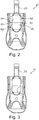
Figur 1 eine schematische Darstellung eines Ausschnitts einer Vorrichtung zur extrakorporalen Blutbehandlung, -
Figur 2 eine Aufsicht auf ein Verrieglungselement mit einer erfindungsgemäßen Koppelstruktur, -
Figur 3 eine weitere Aufsicht auf das Verrieglungselement derFigur 2 , -
Figur 4 einen vergrößerten Ausschnitt einer erfindungsgemäßen Koppelstruktur, -
Figur 5 eine Unteransicht eines Rotors mit einer erfindungsgemäßen Koppelstruktur in einem ersten Betriebszustand, -
Figur 6 eine Unteransicht des Rotors in einem zweiten Betriebszustand und -
Figur 7 eine Unteransicht des Rotors in einem dritten Betriebszustand. -
Figur 1 zeigt beispielhaft einen Ausschnitt einer Vorrichtung zur extrakorporalen Blutbehandlung nach der Erfindung. Gezeigt ist im Wesentlichen der gesamte extrakorporale Blutkreislauf der Vorrichtung. Dieser weist eine arterielle Blutleitung 1 auf, mittels der Blut von einem nicht gezeigten Patienten zu einer modular aufgebauten Peristaltikpumpe 2 der Behandlungsvorrichtung geführt wird. Vor der Peristaltikpumpe 2 ist ein arterieller Druckabnehmer 3 vorgesehen, mit dem der Druck vor der Peristaltikpumpe 2, also der niederdruckseitige Druck gemessen wird. Hochdruckseitig der Peristaltikpumpe 2 führt eine Hochdruckblutleitung 4 zu einem arteriellen Blutfänger 5. Unmittelbar am Ausgang der Peristaltikpumpe 2 kann mittels einer Zuleitung 6 und einer Pumpe 7 Zusatzstoff in das im System befindlichen Blut gegeben werden, z.B. Heparin zur Blutverdünnung. - Vom arteriellen Blutfänger 5 führt eine Leitung 8 unter Hochdruck stehendes aber noch unbehandeltes, mit Schlackenstoffen belastetes Blut zu einem Dialysator 9. Diesem wird eingangsseitig Dialysierflüssigkeit über eine Dialysierflüssigkeitszuleitung 10 zugeführt. Im Dialysator 9 wird Blut in bekannter Weise mittels der Dialysierflüssigkeit behandelt, z.B. gereinigt. Verbrauchte Dialysierflüssigkeit wird über eine Dialysierflüssigkeitsableitung 11 vom Dialysator 9 entfernt und einer nicht dargestellten Entsorgung oder Aufbereitung zugeführt. Behandeltes Blut wird mittels einer Blutableitung 12 vom Dialysator 9 zu einem venösen Luftfänger 13 geleitet, wo mittels einer Luftfalle 14 Luft abgeschieden wird. Am venösen Luftfänger 13 ist ein venöser Druckaufnehmer 15 vorgesehen, mit dem der venöse Druck, also der hochdruckseitige Druck, erfasst wird. Von der Luftfalle 14 wird behandeltes Blut über eine venöse Blutleitung 16 zurück zum Patienten geleitet. Dargestellt in
Figur 1 ist auch eine Einheit 17 zur Überwachung und Steuerung der Vorrichtung. Die Vorrichtung zur extrakorporalen Blutbehandlung ist mit einem Gehäuse 100 gekapselt, das zumindest teilweise als Blechformteil ausgebildet ist. - Die Peristaltikpumpe 2 weist einen in
Figur 1 angedeuteten Rotor 18 und ein ebenfalls angedeutetes Pumpengehäuse 19 mit einer Führungsfläche auf. Zwischen dem Rotor 18 und der Führungsfläche des Pumpengehäuses 19 ist eine elastisch verformbare Fluidleitung 20 angeordnet, die eingangsseitig mit der arteriellen Blutleitung 1 und ausgangsseitig mit der Hockdruckblutleitung 4 verbunden ist. Die Fluidleitung 20 wird durch die Wirkung des Rotors 18 zwischen diesem und der Führungsfläche des Pumpengehäuses 19 verformt und zusammengequetscht, derart, dass eine Fluidförderung von der arteriellen Blutleitung 1 zur Hochdruckblutleitung 4 bewirkt wird. -
Figur 2 zeigt ein Verriegelungselement 21 zur Verriegelung des Rotors 18 auf einer in denFiguren 4 bis 7 erkennbaren Antriebswelle 22 der Dialysemaschine. Das Verriegelungselement 21 weist eine Schwenklasche 23 auf, mit der es schwenkbar am Rotor 18 festlegbar ist. In dem Verriegelungselement 21 ist eine Ausnehmung ausgebildet, deren Wände 24, 25 jeweils eine zweite Führungskontur im Sinne der Erfindung bilden. - Die
Figuren 5 bis 7 zeigen die zweite Führungskontur 24, 25 des Verriegelungselements 21 in Eingriff mit der Antriebswelle 22. Diese ist beidseitig parallel zu ihrer Rotationsachse abgeflacht ausgebildet und weist einander diametral gegenüberliegend zwei erste Führungskonturen in Form von Abflachungen oder Führungsebenen 26, 27 auf. Diese Führungsebenen 26, 27 sind eben und zueinander parallel ausgebildet. Hingegen sind die Führungsflächen 24, 25 der ersten Führungskontur gerundet mit einem ersten Radius R1 und einem zweiten Radius R2 ausgebildet. Der erste Radius kann nach der Erfindung ca. 5mm bis ca. 25mm, bevorzugter von ca. 10mm bis ca. 20mm, noch bevorzugter von ca. 15mm betragen. Der zweite Radius beträgt vorzugsweise ca. 3mm. In denFiguren 5 bis 7 sind des Weiteren Anpressrollen 29, 30 des Rotors 18 gezeigt, die mit der Fluidleitung 20 zusammenwirken und diese zur Förderung von Fluid dadurch zusammenquetschen. Die Anpressrollen 29, 30 sind jeweils an einem Schwenkarm 31 bzw. 32 drehbar gelagert, der jeweils mit einer Druckfeder 33, 34 in eine Anlage an der Fluidleitung 20 vorgespannt sind. Die Schwenkarme 31, 32 sind jeweils um eine Schwenkachse 35, 36 schwenkbar. - Befindet sich eine der Anpressrollen 29, 30 nicht mit der Fluidleitung 20 in quetschendem Eingriff, ist deren Schwenkarm 31 bzw. 32 durch die Wirkung der entsprechenden Druckfeder 33, 34 nach außen, also von der Antriebswelle 22 fort geschwenkt. Im Einlaufbereich gelangt die entsprechende Anpressrolle 29, 30 mit der Fluidleitung 20 in Kontakt und wird infolge des sich bei fortwährender Rotation verringernden Abstand zwischen der Anpressrolle 29, 30 zur Stützfläche in Richtung der Antriebswelle 22 nach innen verschwenkt. Nach Passieren des Einlaufabschnitts befindet sich die entsprechende Anpressrolle 29, 30 im Förderabschnitt der Fluidleitung 20 und quetscht dies fluidfördernd zusammen. Nach Durchlaufen des Förderabschnitts gelangt die entsprechende Anpressrolle 29, 30 in den Auslaufabschnitt, bei dessen Durchlaufen sich der radiale Abstand der Anpressrolle 29. 30 von der Führungsfläche wieder vergrößert und der entsprechende Schwenkarm 31, 32 infolge der geringer werdenden durch die Fluidleitung 20 ausgeübten Druckkraft wieder nach außen (fort von der Antriebswelle 22) schwenkt. Der maximale relative Schwenkwinkel α zwischen dem Rotor 18 und der Antriebswelle 22, der bei maximalen Vorlauf vorliegt, ist in
Figur 7 eingezeichnet. -
Figur 4 zeigt in einer Vergrößerung, dass zwischen den gerundeten Führungsflächen 24, 25 der zweiten Führungskontur und den ebenen Führungsebenen der ersten Führungskontur ein Spalt 28 gebildet ist, der ein Spiel in Rotationsrichtung bereitstellt. Es ist gut zu erkennen, dass die erste Führungskontur 26, 27 bei einer Relativrotation von Rotor 18 zur Antriebswelle 22 auf der zweiten Führungskontur 24, 25 abrollen kann. Dieser Abrollprozess oder die relative Rotation zwischen dem Rotor 18 und der Antriebswelle 22 wird besonders bei einem Vergleich derFiguren 5 ,6 und 7 deutlich. InFigur 5 ist ein Betriebszustand gezeigt, bei dem die Antriebswelle 22 mit dem Rotor 18 in einer Arbeitsstellung oder Neutralstellung in Eingriff steht. Diese Stellung liegt vor, wenn sich keine der beiden Anpressrollen 29, 30 im Einlaufbereich oder im Auslaufbereich befindet. Befindet sich eine der Rollen 29, 30 im Bereich des Pumpenauslaufs (wo sich die Rolle von der Fluidleitung abhebt), wird der Rotor 18 durch die Anpresskraft der entsprechenden Druckfeder 33, 34 in Drehrichtung (in den Figuren im Uhrzeigersinn) beschleunigt und dreht sich daher zeitweise schneller als die Abtriebswelle 22. Dieser Zustand (Vorlauf) ist in denFiguren 6 und 7 dargestellt. Infolge des Spiels 28 wird die vorstehend beschriebene Relativpositionierung zwischen Rotor 18 und Antriebswelle 22 und werden damit die beschriebenen Schwankungen von Kräften und Momenten nicht auf die letztere übertragen.
Claims (11)
- Peristaltikpumpe (2) einer Vorrichtung zur extrakorporalen Blutbehandlung, insbesondere einer Dialysemaschine, zum Fördern von Fluid in der Vorrichtung, welche Peristaltikpumpe (2) einen von einer Antriebswelle (22) drehangetriebenen Rotor (18) aufweist, der mit einer elastisch verformbaren Fluidleitung (20) eine Querschnittsverengung ausbildend zusammenwirkt, wobei die Querschnittsverengung zur Fluidförderung durch Rotation des Rotors (18) entlang der Fluidleitung (20) deplatziert wird und wobei der Rotor (18) mit der Antriebswelle (22) mittels einer Koppelstruktur (24, 25, 26, 27) drehmomentübertragend gekoppelt ist,
dadurch gekennzeichnet, dass
die Koppelstruktur (24, 25, 26, 27) den Rotor (18) und die Antriebswelle (22) mit einem Spiel (28) in Rotationsrichtung zueinander koppelt. - Peristaltikpumpe (2) nach Anspruch 1, dadurch gekennzeichnet, dass der Rotor (18) und die Antriebswelle (22) lösbar miteinander gekoppelt sind.
- Peristaltikpumpe (2) nach Anspruch 1 oder 2, dadurch gekennzeichnet, dass die Koppelstruktur (24, 25, 26, 27) zumindest eine parallel zur Rotationsachse ausgebildete ebene erste Führungskontur (26, 27) aufweist.
- Peristaltikpumpe (2) nach Anspruch 3, dadurch gekennzeichnet, dass die Koppelstruktur (24, 25, 26, 27) zwei zueinander parallele ebene erste Führungskonturen (26, 27) auf einander diametral gegenüberliegenden Seiten der Rotationsachse aufweist.
- Peristaltikpumpe nach einem der vorstehenden Ansprüche, dadurch gekennzeichnet, dass die Koppelstruktur (24, 25, 26, 27) zumindest eine zweite Führungskontur (24, 25) aufweist, die aus zumindest zwei Führungsflächen (24, 25) gebildet ist, die jeweils parallel zur Rotationsachse und zueinander schräg angeordnet sind.
- Peristaltikpumpe (2) nach Anspruch 5, dadurch gekennzeichnet, dass die zweite Führungskontur (24, 25) im Übergang zwischen deren beiden Führungsflächen (24, 25) gerundet ausgebildet ist, vorzugsweise mit einem Radius (R1) von ca. 5mm bis ca. 25mm, bevorzugter von ca. 10mm bis ca. 20mm, noch bevorzugter von ca. 15mm.
- Peristaltikpumpe (2) nach einem der vorstehenden Ansprüche, dadurch gekennzeichnet, dass die zweite Führungskontur (24, 25) gerundet ausgebildet ist, vorzugsweise mit einem Radius (R1) von ca. 5mm bis ca. 25mm, bevorzugter von ca. 10mm bis ca. 20mm, noch bevorzugter von ca. 15mm.
- Peristaltikpumpe (2) nach einem der Ansprüche 5 bis 7, dadurch gekennzeichnet, dass die Koppelstruktur (24, 25, 26, 27) zwei derartige zweite Führungskonturen (24, 25) auf einander diametral gegenüberliegenden Seiten der Rotationsachse aufweist.
- Peristaltikpumpe (2) nach einem der Ansprüche 2 bis 4, dadurch gekennzeichnet, dass die Antriebswelle (22) oder der Rotor (18) eine mittige Nut oder beidseitige Abflachungen aufweist.
- Peristaltikpumpe (2) nach einem der vorstehenden Ansprüche, dadurch gekennzeichnet, dass der Rotor (18) mittels eines Verriegelungselements (21) mit der Antriebswelle (22) koppelbar ist oder das Verriegelungselement (21) aufweist, wobei die erste Führungskontur (26, 27) oder die zweite Führungskontur (24, 25) an dem Verriegelungselement (21) ausgebildet sind.
- Peristaltikpumpe (2) nach einem der vorstehenden Ansprüche, dadurch gekennzeichnet, dass das Verriegelungselement (21) um eine Schwenkachse (23) quer zur Rotationsachse schwenkbar am Rotor (18) angeordnet ist und in eine den Rotor (18) und die Antriebwelle (22) über die Koppelstruktur (24, 25, 26, 27) miteinander koppelnde Verriegelungsstellung und in eine den Rotor (18) und die Antriebswelle (22) voneinander entkoppelnde Entriegelungsstellung positionierbar ist.
Applications Claiming Priority (1)
| Application Number | Priority Date | Filing Date | Title |
|---|---|---|---|
| DE102016114959.4A DE102016114959A1 (de) | 2016-08-11 | 2016-08-11 | Peristaltikpumpe mit rotatorischem Spiel |
Publications (2)
| Publication Number | Publication Date |
|---|---|
| EP3281654A1 true EP3281654A1 (de) | 2018-02-14 |
| EP3281654B1 EP3281654B1 (de) | 2019-04-03 |
Family
ID=59520827
Family Applications (1)
| Application Number | Title | Priority Date | Filing Date |
|---|---|---|---|
| EP17184562.1A Active EP3281654B1 (de) | 2016-08-11 | 2017-08-02 | Peristaltikpumpe mit rotatorischem spiel |
Country Status (5)
| Country | Link |
|---|---|
| US (1) | US10617811B2 (de) |
| EP (1) | EP3281654B1 (de) |
| JP (1) | JP6668297B2 (de) |
| CN (2) | CN107715202B (de) |
| DE (1) | DE102016114959A1 (de) |
Cited By (1)
| Publication number | Priority date | Publication date | Assignee | Title |
|---|---|---|---|---|
| EP4474645A1 (de) * | 2023-06-07 | 2024-12-11 | B. Braun Avitum AG | Peristaltikpumpe |
Families Citing this family (2)
| Publication number | Priority date | Publication date | Assignee | Title |
|---|---|---|---|---|
| DE102018113616A1 (de) * | 2018-06-07 | 2019-12-12 | Prominent Gmbh | Peristaltikpumpe |
| DE102023115077A1 (de) * | 2023-06-07 | 2024-12-12 | B.Braun Avitum Ag | Schlauchrollenpumpe |
Citations (4)
| Publication number | Priority date | Publication date | Assignee | Title |
|---|---|---|---|---|
| US4432707A (en) * | 1982-06-21 | 1984-02-21 | Anko Motors, Inc. | Roller assembly for peristaltic pump |
| US6041709A (en) * | 1998-11-12 | 2000-03-28 | Usadvantage, Inc. | Peristaltic pump for pumping ink or cleaning fluids in a printing machine |
| US20050238515A1 (en) * | 2004-04-27 | 2005-10-27 | Hewlett-Packard Development Company., L.P. | Peristaltic pump |
| US20070148022A1 (en) * | 2004-03-10 | 2007-06-28 | Zaijun Cheng | Peristaltic pump |
Family Cites Families (13)
| Publication number | Priority date | Publication date | Assignee | Title |
|---|---|---|---|---|
| US2348071A (en) * | 1942-06-13 | 1944-05-02 | Johnstone Robert Mcc | Shaft coupling |
| US3737256A (en) | 1971-07-16 | 1973-06-05 | Sarns Inc | Peristaltic pump construction |
| US4527323A (en) | 1983-10-11 | 1985-07-09 | Cole-Parmer Instrument Company | Tubing loading key |
| US4551115A (en) * | 1984-05-23 | 1985-11-05 | Simpson Industries, Inc. | Driveshaft coupling with elastomer damper |
| US5657000A (en) | 1995-06-02 | 1997-08-12 | Cobe Laboratories, Inc. | Peristaltic pump occlusion detector and adjuster |
| US5759017A (en) | 1996-01-31 | 1998-06-02 | Medtronic Electromedics, Inc. | Peristaltic pump and tube loading system |
| EP1117933B2 (de) * | 1998-09-30 | 2013-04-17 | ixetic Hückeswagen GmbH | Vakuumpumpe |
| US8393879B2 (en) | 2004-04-27 | 2013-03-12 | Hewlett-Packard Development Company, L.P. | Peristaltic pump |
| JP5508243B2 (ja) * | 2010-12-07 | 2014-05-28 | 株式会社ジェイテクト | 操舵伝達軸と自在継手のヨークの結合構造及び車両用操舵装置 |
| JP5972590B2 (ja) * | 2012-02-07 | 2016-08-17 | オイレス工業株式会社 | 回転伝達部材、軸直結型カップリングおよび軸連結機構 |
| DE102012105913A1 (de) | 2012-07-03 | 2014-01-09 | B. Braun Avitum Ag | Schlauchrollenpumpe mit einem auto-orientierbaren und -verriegelbaren Rotor sowie medizinisches Gerät zur extrakorporalen Blutbehandlung mit Schlauchrollenpumpe |
| GB201217798D0 (en) | 2012-10-04 | 2012-11-14 | Quanta Fluid Solutions Ltd | Pump rotor |
| DE102017103857A1 (de) * | 2017-02-24 | 2018-08-30 | B. Braun Avitum Ag | Flüssigkeitspumpe |
-
2016
- 2016-08-11 DE DE102016114959.4A patent/DE102016114959A1/de not_active Withdrawn
-
2017
- 2017-08-02 EP EP17184562.1A patent/EP3281654B1/de active Active
- 2017-08-02 US US15/666,888 patent/US10617811B2/en active Active
- 2017-08-08 JP JP2017152943A patent/JP6668297B2/ja active Active
- 2017-08-11 CN CN201710684648.9A patent/CN107715202B/zh active Active
- 2017-08-11 CN CN201721002153.5U patent/CN208989821U/zh active Active
Patent Citations (4)
| Publication number | Priority date | Publication date | Assignee | Title |
|---|---|---|---|---|
| US4432707A (en) * | 1982-06-21 | 1984-02-21 | Anko Motors, Inc. | Roller assembly for peristaltic pump |
| US6041709A (en) * | 1998-11-12 | 2000-03-28 | Usadvantage, Inc. | Peristaltic pump for pumping ink or cleaning fluids in a printing machine |
| US20070148022A1 (en) * | 2004-03-10 | 2007-06-28 | Zaijun Cheng | Peristaltic pump |
| US20050238515A1 (en) * | 2004-04-27 | 2005-10-27 | Hewlett-Packard Development Company., L.P. | Peristaltic pump |
Cited By (1)
| Publication number | Priority date | Publication date | Assignee | Title |
|---|---|---|---|---|
| EP4474645A1 (de) * | 2023-06-07 | 2024-12-11 | B. Braun Avitum AG | Peristaltikpumpe |
Also Published As
| Publication number | Publication date |
|---|---|
| JP6668297B2 (ja) | 2020-03-18 |
| CN208989821U (zh) | 2019-06-18 |
| US10617811B2 (en) | 2020-04-14 |
| EP3281654B1 (de) | 2019-04-03 |
| DE102016114959A1 (de) | 2018-02-15 |
| JP2018029957A (ja) | 2018-03-01 |
| CN107715202B (zh) | 2020-06-05 |
| CN107715202A (zh) | 2018-02-23 |
| US20180043074A1 (en) | 2018-02-15 |
Similar Documents
| Publication | Publication Date | Title |
|---|---|---|
| EP3061473B1 (de) | Schlauchrollenpumpe mit winkelvariablen andruckrollen | |
| DE102007020573B4 (de) | Schlauchrollenpumpe | |
| DE3326784C2 (de) | Peristaltisch arbeitende Rollenpumpe | |
| WO2011124388A1 (de) | Absaugsystem zum absaugen einer körperflüssigkeit | |
| EP3281654B1 (de) | Peristaltikpumpe mit rotatorischem spiel | |
| EP2924288B1 (de) | Schlauchpumpe mit Ausfädeleinrichtung | |
| EP2682604B1 (de) | Schlauchrollenpumpe mit einem auto-orientierbaren und -verriegelbaren Rotor sowie medizinisches Gerät zur extrakorporalen Blutbehandlung mit Schlauchrollenpumpe | |
| EP3366923B1 (de) | Flüssigkeitspumpe | |
| EP4072648B1 (de) | Schlauchpumpe zum fördern von medizinischen fluiden | |
| CH679944A5 (de) | ||
| EP2682605B1 (de) | Schlauchrollenpumpe mit einem verriegelbaren Rotor und medizinisches Gerät zur extrakorporalen Blutbehandlung mit Schlauchrollenpumpe | |
| EP2667906B1 (de) | Schlauchpumpe und hiermit ausgestattete blutbehandlungsvorrichtung | |
| WO2021229096A1 (de) | Medizinische schlauchpumpe mit stempelelementen und zugehörige schlauchanordnung | |
| WO2007028429A1 (de) | Zahnradpumpe | |
| DE102018113616A1 (de) | Peristaltikpumpe | |
| DE112015001873B4 (de) | Schlauchpumpe und Fluidförderverfahren | |
| DE102020213988A1 (de) | Peristaltikpumpe für eine Vorrichtung zur extrakorporalen Blutbehandlung | |
| WO2018189041A1 (de) | Schraubenverdichteranordnung with synchronsiation gears and transmission gearing | |
| WO2018036875A1 (de) | Spritzenpumpe mit verbesserter einlegeprozedur von spritzen zur vermeidung ungewollter bolusgaben | |
| EP4474000B1 (de) | Aufsteck- und sicherungsvorrichtung des rotors einer peristaltischen blutpumpe | |
| EP0174535A1 (de) | Rotationsschlauchpumpe | |
| DE102009043245B4 (de) | Schlauchpumpe | |
| DE69301271T2 (de) | Peristaltische Pumpe mit elastischer Statoraussenaufhängung | |
| EP4371916A1 (de) | Fördereinrichtung zur gerichteten förderung pulverförmiger stoffe sowie zugehöriges verfahren | |
| DE102023136602A1 (de) | Rollenpumpe für ein Milchmodul einer Getränkezubereitungsvorrichtung, Formschlauch zur Medienführung in einer Rollenpumpe und Milchmodul für eine Getränkezubereitungsvorrichtung |
Legal Events
| Date | Code | Title | Description |
|---|---|---|---|
| PUAI | Public reference made under article 153(3) epc to a published international application that has entered the european phase |
Free format text: ORIGINAL CODE: 0009012 |
|
| STAA | Information on the status of an ep patent application or granted ep patent |
Free format text: STATUS: THE APPLICATION HAS BEEN PUBLISHED |
|
| AK | Designated contracting states |
Kind code of ref document: A1 Designated state(s): AL AT BE BG CH CY CZ DE DK EE ES FI FR GB GR HR HU IE IS IT LI LT LU LV MC MK MT NL NO PL PT RO RS SE SI SK SM TR |
|
| AX | Request for extension of the european patent |
Extension state: BA ME |
|
| STAA | Information on the status of an ep patent application or granted ep patent |
Free format text: STATUS: REQUEST FOR EXAMINATION WAS MADE |
|
| 17P | Request for examination filed |
Effective date: 20180713 |
|
| GRAP | Despatch of communication of intention to grant a patent |
Free format text: ORIGINAL CODE: EPIDOSNIGR1 |
|
| STAA | Information on the status of an ep patent application or granted ep patent |
Free format text: STATUS: GRANT OF PATENT IS INTENDED |
|
| INTG | Intention to grant announced |
Effective date: 20181023 |
|
| GRAS | Grant fee paid |
Free format text: ORIGINAL CODE: EPIDOSNIGR3 |
|
| GRAA | (expected) grant |
Free format text: ORIGINAL CODE: 0009210 |
|
| STAA | Information on the status of an ep patent application or granted ep patent |
Free format text: STATUS: THE PATENT HAS BEEN GRANTED |
|
| AK | Designated contracting states |
Kind code of ref document: B1 Designated state(s): AL AT BE BG CH CY CZ DE DK EE ES FI FR GB GR HR HU IE IS IT LI LT LU LV MC MK MT NL NO PL PT RO RS SE SI SK SM TR |
|
| REG | Reference to a national code |
Ref country code: GB Ref legal event code: FG4D Free format text: NOT ENGLISH |
|
| REG | Reference to a national code |
Ref country code: CH Ref legal event code: EP Ref country code: AT Ref legal event code: REF Ref document number: 1114945 Country of ref document: AT Kind code of ref document: T Effective date: 20190415 |
|
| REG | Reference to a national code |
Ref country code: DE Ref legal event code: R096 Ref document number: 502017001037 Country of ref document: DE |
|
| REG | Reference to a national code |
Ref country code: IE Ref legal event code: FG4D Free format text: LANGUAGE OF EP DOCUMENT: GERMAN |
|
| REG | Reference to a national code |
Ref country code: SE Ref legal event code: TRGR |
|
| REG | Reference to a national code |
Ref country code: NL Ref legal event code: MP Effective date: 20190403 |
|
| REG | Reference to a national code |
Ref country code: LT Ref legal event code: MG4D |
|
| PG25 | Lapsed in a contracting state [announced via postgrant information from national office to epo] |
Ref country code: NL Free format text: LAPSE BECAUSE OF FAILURE TO SUBMIT A TRANSLATION OF THE DESCRIPTION OR TO PAY THE FEE WITHIN THE PRESCRIBED TIME-LIMIT Effective date: 20190403 |
|
| PG25 | Lapsed in a contracting state [announced via postgrant information from national office to epo] |
Ref country code: PT Free format text: LAPSE BECAUSE OF FAILURE TO SUBMIT A TRANSLATION OF THE DESCRIPTION OR TO PAY THE FEE WITHIN THE PRESCRIBED TIME-LIMIT Effective date: 20190803 Ref country code: ES Free format text: LAPSE BECAUSE OF FAILURE TO SUBMIT A TRANSLATION OF THE DESCRIPTION OR TO PAY THE FEE WITHIN THE PRESCRIBED TIME-LIMIT Effective date: 20190403 Ref country code: LT Free format text: LAPSE BECAUSE OF FAILURE TO SUBMIT A TRANSLATION OF THE DESCRIPTION OR TO PAY THE FEE WITHIN THE PRESCRIBED TIME-LIMIT Effective date: 20190403 Ref country code: CZ Free format text: LAPSE BECAUSE OF FAILURE TO SUBMIT A TRANSLATION OF THE DESCRIPTION OR TO PAY THE FEE WITHIN THE PRESCRIBED TIME-LIMIT Effective date: 20190403 Ref country code: FI Free format text: LAPSE BECAUSE OF FAILURE TO SUBMIT A TRANSLATION OF THE DESCRIPTION OR TO PAY THE FEE WITHIN THE PRESCRIBED TIME-LIMIT Effective date: 20190403 Ref country code: HR Free format text: LAPSE BECAUSE OF FAILURE TO SUBMIT A TRANSLATION OF THE DESCRIPTION OR TO PAY THE FEE WITHIN THE PRESCRIBED TIME-LIMIT Effective date: 20190403 Ref country code: AL Free format text: LAPSE BECAUSE OF FAILURE TO SUBMIT A TRANSLATION OF THE DESCRIPTION OR TO PAY THE FEE WITHIN THE PRESCRIBED TIME-LIMIT Effective date: 20190403 Ref country code: NO Free format text: LAPSE BECAUSE OF FAILURE TO SUBMIT A TRANSLATION OF THE DESCRIPTION OR TO PAY THE FEE WITHIN THE PRESCRIBED TIME-LIMIT Effective date: 20190703 |
|
| PG25 | Lapsed in a contracting state [announced via postgrant information from national office to epo] |
Ref country code: PL Free format text: LAPSE BECAUSE OF FAILURE TO SUBMIT A TRANSLATION OF THE DESCRIPTION OR TO PAY THE FEE WITHIN THE PRESCRIBED TIME-LIMIT Effective date: 20190403 Ref country code: RS Free format text: LAPSE BECAUSE OF FAILURE TO SUBMIT A TRANSLATION OF THE DESCRIPTION OR TO PAY THE FEE WITHIN THE PRESCRIBED TIME-LIMIT Effective date: 20190403 Ref country code: LV Free format text: LAPSE BECAUSE OF FAILURE TO SUBMIT A TRANSLATION OF THE DESCRIPTION OR TO PAY THE FEE WITHIN THE PRESCRIBED TIME-LIMIT Effective date: 20190403 Ref country code: GR Free format text: LAPSE BECAUSE OF FAILURE TO SUBMIT A TRANSLATION OF THE DESCRIPTION OR TO PAY THE FEE WITHIN THE PRESCRIBED TIME-LIMIT Effective date: 20190704 Ref country code: BG Free format text: LAPSE BECAUSE OF FAILURE TO SUBMIT A TRANSLATION OF THE DESCRIPTION OR TO PAY THE FEE WITHIN THE PRESCRIBED TIME-LIMIT Effective date: 20190703 |
|
| PG25 | Lapsed in a contracting state [announced via postgrant information from national office to epo] |
Ref country code: IS Free format text: LAPSE BECAUSE OF FAILURE TO SUBMIT A TRANSLATION OF THE DESCRIPTION OR TO PAY THE FEE WITHIN THE PRESCRIBED TIME-LIMIT Effective date: 20190803 |
|
| REG | Reference to a national code |
Ref country code: DE Ref legal event code: R097 Ref document number: 502017001037 Country of ref document: DE |
|
| PG25 | Lapsed in a contracting state [announced via postgrant information from national office to epo] |
Ref country code: SK Free format text: LAPSE BECAUSE OF FAILURE TO SUBMIT A TRANSLATION OF THE DESCRIPTION OR TO PAY THE FEE WITHIN THE PRESCRIBED TIME-LIMIT Effective date: 20190403 Ref country code: RO Free format text: LAPSE BECAUSE OF FAILURE TO SUBMIT A TRANSLATION OF THE DESCRIPTION OR TO PAY THE FEE WITHIN THE PRESCRIBED TIME-LIMIT Effective date: 20190403 Ref country code: EE Free format text: LAPSE BECAUSE OF FAILURE TO SUBMIT A TRANSLATION OF THE DESCRIPTION OR TO PAY THE FEE WITHIN THE PRESCRIBED TIME-LIMIT Effective date: 20190403 Ref country code: DK Free format text: LAPSE BECAUSE OF FAILURE TO SUBMIT A TRANSLATION OF THE DESCRIPTION OR TO PAY THE FEE WITHIN THE PRESCRIBED TIME-LIMIT Effective date: 20190403 |
|
| PLBE | No opposition filed within time limit |
Free format text: ORIGINAL CODE: 0009261 |
|
| STAA | Information on the status of an ep patent application or granted ep patent |
Free format text: STATUS: NO OPPOSITION FILED WITHIN TIME LIMIT |
|
| PG25 | Lapsed in a contracting state [announced via postgrant information from national office to epo] |
Ref country code: SM Free format text: LAPSE BECAUSE OF FAILURE TO SUBMIT A TRANSLATION OF THE DESCRIPTION OR TO PAY THE FEE WITHIN THE PRESCRIBED TIME-LIMIT Effective date: 20190403 |
|
| 26N | No opposition filed |
Effective date: 20200106 |
|
| PG25 | Lapsed in a contracting state [announced via postgrant information from national office to epo] |
Ref country code: TR Free format text: LAPSE BECAUSE OF FAILURE TO SUBMIT A TRANSLATION OF THE DESCRIPTION OR TO PAY THE FEE WITHIN THE PRESCRIBED TIME-LIMIT Effective date: 20190403 |
|
| PG25 | Lapsed in a contracting state [announced via postgrant information from national office to epo] |
Ref country code: LU Free format text: LAPSE BECAUSE OF NON-PAYMENT OF DUE FEES Effective date: 20190802 Ref country code: MC Free format text: LAPSE BECAUSE OF FAILURE TO SUBMIT A TRANSLATION OF THE DESCRIPTION OR TO PAY THE FEE WITHIN THE PRESCRIBED TIME-LIMIT Effective date: 20190403 Ref country code: SI Free format text: LAPSE BECAUSE OF FAILURE TO SUBMIT A TRANSLATION OF THE DESCRIPTION OR TO PAY THE FEE WITHIN THE PRESCRIBED TIME-LIMIT Effective date: 20190403 |
|
| REG | Reference to a national code |
Ref country code: BE Ref legal event code: MM Effective date: 20190831 |
|
| PG25 | Lapsed in a contracting state [announced via postgrant information from national office to epo] |
Ref country code: FR Free format text: LAPSE BECAUSE OF NON-PAYMENT OF DUE FEES Effective date: 20190831 Ref country code: IE Free format text: LAPSE BECAUSE OF NON-PAYMENT OF DUE FEES Effective date: 20190802 |
|
| PG25 | Lapsed in a contracting state [announced via postgrant information from national office to epo] |
Ref country code: BE Free format text: LAPSE BECAUSE OF NON-PAYMENT OF DUE FEES Effective date: 20190831 |
|
| REG | Reference to a national code |
Ref country code: DE Ref legal event code: R079 Ref document number: 502017001037 Country of ref document: DE Free format text: PREVIOUS MAIN CLASS: A61M0001100000 Ipc: A61M0060000000 |
|
| REG | Reference to a national code |
Ref country code: CH Ref legal event code: PL |
|
| PG25 | Lapsed in a contracting state [announced via postgrant information from national office to epo] |
Ref country code: LI Free format text: LAPSE BECAUSE OF NON-PAYMENT OF DUE FEES Effective date: 20200831 Ref country code: CH Free format text: LAPSE BECAUSE OF NON-PAYMENT OF DUE FEES Effective date: 20200831 |
|
| PG25 | Lapsed in a contracting state [announced via postgrant information from national office to epo] |
Ref country code: CY Free format text: LAPSE BECAUSE OF FAILURE TO SUBMIT A TRANSLATION OF THE DESCRIPTION OR TO PAY THE FEE WITHIN THE PRESCRIBED TIME-LIMIT Effective date: 20190403 |
|
| PG25 | Lapsed in a contracting state [announced via postgrant information from national office to epo] |
Ref country code: MT Free format text: LAPSE BECAUSE OF FAILURE TO SUBMIT A TRANSLATION OF THE DESCRIPTION OR TO PAY THE FEE WITHIN THE PRESCRIBED TIME-LIMIT Effective date: 20190403 Ref country code: HU Free format text: LAPSE BECAUSE OF FAILURE TO SUBMIT A TRANSLATION OF THE DESCRIPTION OR TO PAY THE FEE WITHIN THE PRESCRIBED TIME-LIMIT; INVALID AB INITIO Effective date: 20170802 |
|
| GBPC | Gb: european patent ceased through non-payment of renewal fee |
Effective date: 20210802 |
|
| PG25 | Lapsed in a contracting state [announced via postgrant information from national office to epo] |
Ref country code: MK Free format text: LAPSE BECAUSE OF FAILURE TO SUBMIT A TRANSLATION OF THE DESCRIPTION OR TO PAY THE FEE WITHIN THE PRESCRIBED TIME-LIMIT Effective date: 20190403 |
|
| PG25 | Lapsed in a contracting state [announced via postgrant information from national office to epo] |
Ref country code: GB Free format text: LAPSE BECAUSE OF NON-PAYMENT OF DUE FEES Effective date: 20210802 |
|
| REG | Reference to a national code |
Ref country code: AT Ref legal event code: MM01 Ref document number: 1114945 Country of ref document: AT Kind code of ref document: T Effective date: 20220802 |
|
| PG25 | Lapsed in a contracting state [announced via postgrant information from national office to epo] |
Ref country code: AT Free format text: LAPSE BECAUSE OF NON-PAYMENT OF DUE FEES Effective date: 20220802 |
|
| P01 | Opt-out of the competence of the unified patent court (upc) registered |
Effective date: 20231010 |
|
| PGFP | Annual fee paid to national office [announced via postgrant information from national office to epo] |
Ref country code: DE Payment date: 20250819 Year of fee payment: 9 |
|
| PGFP | Annual fee paid to national office [announced via postgrant information from national office to epo] |
Ref country code: IT Payment date: 20250829 Year of fee payment: 9 |
|
| PGFP | Annual fee paid to national office [announced via postgrant information from national office to epo] |
Ref country code: SE Payment date: 20250821 Year of fee payment: 9 |