EP3281603B1 - Surgical tissue marking device with dryer - Google Patents
Surgical tissue marking device with dryer Download PDFInfo
- Publication number
- EP3281603B1 EP3281603B1 EP17185400.3A EP17185400A EP3281603B1 EP 3281603 B1 EP3281603 B1 EP 3281603B1 EP 17185400 A EP17185400 A EP 17185400A EP 3281603 B1 EP3281603 B1 EP 3281603B1
- Authority
- EP
- European Patent Office
- Prior art keywords
- marker
- tip
- lever
- shaft
- marking
- Prior art date
- Legal status (The legal status is an assumption and is not a legal conclusion. Google has not performed a legal analysis and makes no representation as to the accuracy of the status listed.)
- Active
Links
Images


Classifications
-
- A—HUMAN NECESSITIES
- A61—MEDICAL OR VETERINARY SCIENCE; HYGIENE
- A61B—DIAGNOSIS; SURGERY; IDENTIFICATION
- A61B90/00—Instruments, implements or accessories specially adapted for surgery or diagnosis and not covered by any of the groups A61B1/00 - A61B50/00, e.g. for luxation treatment or for protecting wound edges
- A61B90/39—Markers, e.g. radio-opaque or breast lesions markers
-
- A—HUMAN NECESSITIES
- A01—AGRICULTURE; FORESTRY; ANIMAL HUSBANDRY; HUNTING; TRAPPING; FISHING
- A01K—ANIMAL HUSBANDRY; AVICULTURE; APICULTURE; PISCICULTURE; FISHING; REARING OR BREEDING ANIMALS, NOT OTHERWISE PROVIDED FOR; NEW BREEDS OF ANIMALS
- A01K11/00—Marking of animals
- A01K11/005—Branding or tattooing devices for animals
-
- A—HUMAN NECESSITIES
- A61—MEDICAL OR VETERINARY SCIENCE; HYGIENE
- A61B—DIAGNOSIS; SURGERY; IDENTIFICATION
- A61B18/00—Surgical instruments, devices or methods for transferring non-mechanical forms of energy to or from the body
- A61B18/02—Surgical instruments, devices or methods for transferring non-mechanical forms of energy to or from the body by cooling, e.g. cryogenic techniques
-
- A—HUMAN NECESSITIES
- A61—MEDICAL OR VETERINARY SCIENCE; HYGIENE
- A61B—DIAGNOSIS; SURGERY; IDENTIFICATION
- A61B18/00—Surgical instruments, devices or methods for transferring non-mechanical forms of energy to or from the body
- A61B18/04—Surgical instruments, devices or methods for transferring non-mechanical forms of energy to or from the body by heating
-
- A—HUMAN NECESSITIES
- A61—MEDICAL OR VETERINARY SCIENCE; HYGIENE
- A61M—DEVICES FOR INTRODUCING MEDIA INTO, OR ONTO, THE BODY; DEVICES FOR TRANSDUCING BODY MEDIA OR FOR TAKING MEDIA FROM THE BODY; DEVICES FOR PRODUCING OR ENDING SLEEP OR STUPOR
- A61M37/00—Other apparatus for introducing media into the body; Percutany, i.e. introducing medicines into the body by diffusion through the skin
- A61M37/0076—Tattooing apparatus
-
- B—PERFORMING OPERATIONS; TRANSPORTING
- B43—WRITING OR DRAWING IMPLEMENTS; BUREAU ACCESSORIES
- B43K—IMPLEMENTS FOR WRITING OR DRAWING
- B43K27/00—Multiple-point writing implements, e.g. multicolour; Combinations of writing implements
- B43K27/08—Combinations of pens
-
- B—PERFORMING OPERATIONS; TRANSPORTING
- B43—WRITING OR DRAWING IMPLEMENTS; BUREAU ACCESSORIES
- B43K—IMPLEMENTS FOR WRITING OR DRAWING
- B43K29/00—Combinations of writing implements with other articles
-
- B—PERFORMING OPERATIONS; TRANSPORTING
- B43—WRITING OR DRAWING IMPLEMENTS; BUREAU ACCESSORIES
- B43K—IMPLEMENTS FOR WRITING OR DRAWING
- B43K8/00—Pens with writing-points other than nibs or balls
- B43K8/006—Pens with writing-points other than nibs or balls using a spraying system, e.g. airbrushes
-
- B—PERFORMING OPERATIONS; TRANSPORTING
- B43—WRITING OR DRAWING IMPLEMENTS; BUREAU ACCESSORIES
- B43K—IMPLEMENTS FOR WRITING OR DRAWING
- B43K8/00—Pens with writing-points other than nibs or balls
- B43K8/02—Pens with writing-points other than nibs or balls with writing-points comprising fibres, felt, or similar porous or capillary material
-
- A—HUMAN NECESSITIES
- A61—MEDICAL OR VETERINARY SCIENCE; HYGIENE
- A61B—DIAGNOSIS; SURGERY; IDENTIFICATION
- A61B18/00—Surgical instruments, devices or methods for transferring non-mechanical forms of energy to or from the body
- A61B18/18—Surgical instruments, devices or methods for transferring non-mechanical forms of energy to or from the body by applying electromagnetic radiation, e.g. microwaves
- A61B18/20—Surgical instruments, devices or methods for transferring non-mechanical forms of energy to or from the body by applying electromagnetic radiation, e.g. microwaves using laser
-
- A—HUMAN NECESSITIES
- A61—MEDICAL OR VETERINARY SCIENCE; HYGIENE
- A61B—DIAGNOSIS; SURGERY; IDENTIFICATION
- A61B90/00—Instruments, implements or accessories specially adapted for surgery or diagnosis and not covered by any of the groups A61B1/00 - A61B50/00, e.g. for luxation treatment or for protecting wound edges
- A61B90/39—Markers, e.g. radio-opaque or breast lesions markers
- A61B2090/3937—Visible markers
-
- A—HUMAN NECESSITIES
- A61—MEDICAL OR VETERINARY SCIENCE; HYGIENE
- A61B—DIAGNOSIS; SURGERY; IDENTIFICATION
- A61B90/00—Instruments, implements or accessories specially adapted for surgery or diagnosis and not covered by any of the groups A61B1/00 - A61B50/00, e.g. for luxation treatment or for protecting wound edges
- A61B90/39—Markers, e.g. radio-opaque or breast lesions markers
- A61B2090/3937—Visible markers
- A61B2090/395—Visible markers with marking agent for marking skin or other tissue
-
- A—HUMAN NECESSITIES
- A61—MEDICAL OR VETERINARY SCIENCE; HYGIENE
- A61M—DEVICES FOR INTRODUCING MEDIA INTO, OR ONTO, THE BODY; DEVICES FOR TRANSDUCING BODY MEDIA OR FOR TAKING MEDIA FROM THE BODY; DEVICES FOR PRODUCING OR ENDING SLEEP OR STUPOR
- A61M37/00—Other apparatus for introducing media into the body; Percutany, i.e. introducing medicines into the body by diffusion through the skin
- A61M37/0076—Tattooing apparatus
- A61M37/0084—Tattooing apparatus with incorporated liquid feeding device
Definitions
- the present invention relates in general to tools for marking biological tissue during surgical procedures, and, more specifically, to improved accuracy and integrity of tissue marking by drying of the biological tissue.
- a surgeon may first identify and mark locations on tissue to properly orient and locate targeted tissue.
- CABG coronary artery bypass grafting
- a blood vessel is "harvested" (i.e., removed) from its natural location in a patient's body and reattached elsewhere to create a blood flow around a blockage.
- a vessel is removed from the patient's body, it must be prepared for use as a bypass graft.
- Preparation includes ligating (i.e., closing off) each branch stub, injecting a solution into the vein under pressure to test for leaks, and otherwise inspecting the condition of the blood vessel.
- the vessel can be surgically anastomosed to create the bypass.
- a longitudinal guide line along the outer wall of the graft comprised of a methylene blue dye.
- the line is intended to help in laying out the graft by showing if the graft becomes twisted, which could cause kinking and poor blood flow through the bypass.
- a surgeon or physician's assistant has manually marked the vessel using a felt tip pen filled with the methylene blue dye.
- the vessel is kept moist with heparinized saline to preserve it while outside the body. The moisture, however, can cause the dye to "run” or diffuse so that the lines blur. This makes it difficult to achieve the pin-point accuracy desired for many procedures.
- wet tissue marking include 1) marking the internal surface of a live human aortic valve (which are wet from saline and blood) during repair of the valve to indicate suture positions, 2) internally marking cadavers and living animal tissues for various procedures and for marking dissected specimens, and 3) marking the outer surface of wet human eyes.
- a dye such as methylene blue
- other means of marking tissue such as laser scoring, tattooing, heat burning, and cold burning can also be adversely affected by moisture on the tissue surface to be marked.
- the present invention provides tools capable of reducing moisture on biological tissue to enhance the ability to accurately mark desired lines or patterns on the tissue using ink or dye.
- the devices improve surgical outcomes through faster and clearer tissue marking on wet tissue compared to conventional dye marker pens which may tend to produce blurred lines on wet tissue.
- the invention is specified in appended claim 1.
- the invention provides a marking device including a "blow-dry feature" to reduce moisture using a flow of drying gas (e.g., pressurized CO2). Drying of the wet tissue may be short lived since surrounding moisture may quickly spread back to the dried area. Therefore, the marker and dryer nozzle are contained within a common housing which allows the user to quickly switch between the drying and marking functions.
- the marker tip is retractable to shield the marker tip from the gas nozzle to avoid an airbrush effect wherein the dye may be inadvertently dispersed onto the tissue.
- a wet tissue marking system comprises a marking tip, a gas nozzle, and a holding body.
- the holding body contains the marking tip and gas nozzle whereby a user dries a wet tissue surface by metering a drying gas onto the surface and reconfigures the system to mark the surface with the marking tip.
- Documents EP 0 092 359 A2 and US 2003/090011 A1 disclose airbrushing devices and document US 5226419 relates to the simultaneous dispensing of pressurized gas and marking fluid onto a patient's skin.
- FIG. 1 shows a combination tool 10 providing blow dryer and marker functions.
- a handle 11 supports a hollow rod 12 having a nozzle 13 at its distal end.
- a drying gas such as CO2 is supplied to nozzle 13 through rod 12 and handle 11 from an external source 14 connected by a supply tube 15.
- the CO2 gas is commonly available in a surgical facility via a standard luer fitting or a gas cartridge or cylinder, for example.
- a wet tissue area to be marked can be temporarily dried by metering the gas through nozzle 13 toward the area.
- a marker device 16 with a tip 17 is mounted to rod 12 adjacent nozzle 13 by straps 18.
- Tip 17 is preferably comprised of a fine tip surgical marker for methylene dye.
- a laser emitter for ablating tissue to create a mark, a needle or set of needles for creating a tattoo, a heating element for burning a mark, or a cold burn element for burning a mark can be used.
- Figure 2 shows a self-contained device 20 having an overall cylindrical shape similar to a writing pen.
- a felt tip 21 delivers dye or ink from a reservoir 22 within a cylindrical body or tube 23.
- a CO2 nozzle 24 at the other end selectably delivers a gas flow from a CO2 cartridge 25 mounted within body 23 via a valve 26 that is manually controlled by a push button on the side of cylindrical body 23.
- An annular ridge 27 is provided at the longitudinal center of body 23 to assist with gripping and reversing the orientation of the body (i.e., flipping) after the desired area has been dried so that the tissue can be marked as desired.
- Figures 3A and 3B show an alternative embodiment not within the scope of the claim wherein reversing of a device 30 is not required (i.e., the marker and dryer nozzle deploy from the same working end of the cylindrical body).
- a marking tip 31 and gas nozzle 32 are retractable so that each of the drying and marking functions can be performed without interference by the other function (e.g., no air brushing of the dye).
- marking tip 31 is extended from a cylindrical body 33.
- a retractable pen-type structure with a rotating cam body (not shown) activated by a push button 34 at the opposite end of cylindrical body 33 is used for selectably extending tip 31 out from a nozzle opening at the end of body 33.
- tip 31 is retracted.
- a gas nozzle may be extended in order to dispense gas from a cartridge 35.
- FIGS. 4A and 4B show an embodiment according to the invention of a retractable dryer/marker tool 40 in greater detail.
- a gas line 41 from an external supply connects to an internal line 43 via a luer fitting 42.
- Internal line 43 connects to a valve 44 which selectably releases the gas to an internal opening or nozzle 45.
- Valve 44 is opened and closed via a first plunger arm extending into a tubular body 46 from a gas lever 47 that extends longitudinally along the side of tube 46.
- a proximal end of lever 47 attaches to tube 46.
- a second plunger arm 48 interfaces with a stop block 50 carried by an extendable/retractable marker shaft 51.
- a marker tip 52 is disposed at the distal end of shaft 51.
- second plunger arm 48 is not deflected by stop block 50, which allows the first plunger arm to open gas valve 44, thereby metering the drying gas through tubular body 46 and out from an opening 53 in the distal end to dry the target tissue.
- the plunger arms and stop block form an interlock that ensures that tip 52 must be retracted in order for valve 44 to be activated.
- a spring 54 installed over plunger arm 48 urges lever 47 away from tube 46 so that valve 44 is normally turned off. In order to be able to lever 47 to move toward tube 46, shaft 51/tip 52 must be retracted so that stop block 50 is not preventing incursion of plunger arm 48.
- a retractable (i.e., click-type) pen mechanism which includes a spring 56 is used to selectably extend or retract marking tip 52 through opening 53.
- stop block 50 is placed into an interfering condition with second plunger arm 48 except when tip 52 is retracted.
- second plunger arm penetrates to the position shown in Figure 4A which prevent extension of shaft 51 because of interference of stop block 50 and plunger arm 48.
- gas lever 47 is deflected radially outward so that the first plunger arm moves away from gas valve 44, and gas valve 44 closes to prevent gas from being emitted at the distal end.
- an extended internal gas line 60 it may be preferable to provide an extended internal gas line 60 so that free flow of the drying gas initiates beyond a retracted position of the marker tip so that the drying gas is not blown over the marker.
- an internal shield wall or tube 61 can be placed around the marker tip's retracted position to separate the tip from the gas flow.
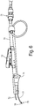
- Figure 6 shows another embodiment wherein a tool body 70 is fitted with a gas supply luer connection 71 at the proximal end and a gas ejection tube 72 at the distal end.
- a thumb activated gas valve 73 is placed behind a finger grip 74 for convenient manipulation of body 70.
- a marking portion 75 includes a dye marker felt tip 76 attached to a distal end of a malleable support shaft 77 that extends from body 70. A user can manually bend shaft 77 in order to configure the placement of tip 76 for better visualization in tight areas such as internal aortic valve sections.
- tip 76 is not retractable.
- a felt tip holder tube and a linkage from a sliding control button could be provided.
- shaft 77 may be pre-bent so that where felt tip 76 is placed for tissue contact, it is held at an angle to main body 70. This affords the user better visibility.
- straight markers would obstruct the place that you are trying to mark.
- a felt tip when it retracts into a bent tube it can return to being straight once it is back inside the tube holder.
Landscapes
- Health & Medical Sciences (AREA)
- Life Sciences & Earth Sciences (AREA)
- Surgery (AREA)
- Engineering & Computer Science (AREA)
- Heart & Thoracic Surgery (AREA)
- Medical Informatics (AREA)
- Veterinary Medicine (AREA)
- Public Health (AREA)
- General Health & Medical Sciences (AREA)
- Animal Behavior & Ethology (AREA)
- Nuclear Medicine, Radiotherapy & Molecular Imaging (AREA)
- Biomedical Technology (AREA)
- Molecular Biology (AREA)
- Otolaryngology (AREA)
- Environmental Sciences (AREA)
- Oral & Maxillofacial Surgery (AREA)
- Pathology (AREA)
- Physics & Mathematics (AREA)
- Plasma & Fusion (AREA)
- Biodiversity & Conservation Biology (AREA)
- Zoology (AREA)
- Animal Husbandry (AREA)
- Birds (AREA)
- Virology (AREA)
- Dermatology (AREA)
- Anesthesiology (AREA)
- Hematology (AREA)
- Surgical Instruments (AREA)
Description
- The present invention relates in general to tools for marking biological tissue during surgical procedures, and, more specifically, to improved accuracy and integrity of tissue marking by drying of the biological tissue.
- In preparation for cutting, suturing, or other surgical steps, a surgeon may first identify and mark locations on tissue to properly orient and locate targeted tissue. For example, in coronary artery bypass grafting (CABG), a blood vessel is "harvested" (i.e., removed) from its natural location in a patient's body and reattached elsewhere to create a blood flow around a blockage. After a vessel is removed from the patient's body, it must be prepared for use as a bypass graft. Preparation includes ligating (i.e., closing off) each branch stub, injecting a solution into the vein under pressure to test for leaks, and otherwise inspecting the condition of the blood vessel. After preparation, the vessel can be surgically anastomosed to create the bypass.
- It has become common for vessel preparation to include application of a longitudinal guide line along the outer wall of the graft comprised of a methylene blue dye. The line is intended to help in laying out the graft by showing if the graft becomes twisted, which could cause kinking and poor blood flow through the bypass. To apply the guide line, a surgeon or physician's assistant has manually marked the vessel using a felt tip pen filled with the methylene blue dye. The vessel is kept moist with heparinized saline to preserve it while outside the body. The moisture, however, can cause the dye to "run" or diffuse so that the lines blur. This makes it difficult to achieve the pin-point accuracy desired for many procedures.
- Other examples of wet tissue marking include 1) marking the internal surface of a live human aortic valve (which are wet from saline and blood) during repair of the valve to indicate suture positions, 2) internally marking cadavers and living animal tissues for various procedures and for marking dissected specimens, and 3) marking the outer surface of wet human eyes.
- In addition to marking with a dye such as methylene blue, other means of marking tissue such as laser scoring, tattooing, heat burning, and cold burning can also be adversely affected by moisture on the tissue surface to be marked.
- The present invention provides tools capable of reducing moisture on biological tissue to enhance the ability to accurately mark desired lines or patterns on the tissue using ink or dye. The devices improve surgical outcomes through faster and clearer tissue marking on wet tissue compared to conventional dye marker pens which may tend to produce blurred lines on wet tissue. The invention is specified in appended claim 1.
- The invention provides a marking device including a "blow-dry feature" to reduce moisture using a flow of drying gas (e.g., pressurized CO2). Drying of the wet tissue may be short lived since surrounding moisture may quickly spread back to the dried area. Therefore, the marker and dryer nozzle are contained within a common housing which allows the user to quickly switch between the drying and marking functions. The marker tip is retractable to shield the marker tip from the gas nozzle to avoid an airbrush effect wherein the dye may be inadvertently dispersed onto the tissue. According to one aspect of the invention, a wet tissue marking system comprises a marking tip, a gas nozzle, and a holding body. The holding body contains the marking tip and gas nozzle whereby a user dries a wet tissue surface by metering a drying gas onto the surface and reconfigures the system to mark the surface with the marking tip. Documents
EP 0 092 359 A2 andUS 2003/090011 A1 disclose airbrushing devices and documentUS 5226419 relates to the simultaneous dispensing of pressurized gas and marking fluid onto a patient's skin. -
-
Figure 1 is a plan view showing one example combination tool for drying and marking biological tissue according to an arrangement that is not within the scope of the claims. -
Figure 2 is a plan view of an arrangement that is not within the scope of the claims including a double-ended marking and drying tool. -
Figures 3A and 3B are plans views of another arrangement that is not within the scope of the claims having a retractable marker and an internal source of drying gas, with the marker extended and retracted, respectively. -
Figures 4A and 4B are diagrammatic views of an embodiment within the scope of claim 1 of a combined marking and drying tool with an interlock mechanism to prevent emission of drying gas when a marker is extended. -
Figure 5 is a diagrammatic view of a modified embodiment within the scope of claim 1. -
Figure 6 is a side view of another embodiment within the scope of claim 1 wherein a marking tip is carried by a malleable shaft. -
Figure 1 shows acombination tool 10 providing blow dryer and marker functions. Ahandle 11 supports ahollow rod 12 having anozzle 13 at its distal end. A drying gas such as CO2 is supplied tonozzle 13 throughrod 12 and handle 11 from anexternal source 14 connected by asupply tube 15. The CO2 gas is commonly available in a surgical facility via a standard luer fitting or a gas cartridge or cylinder, for example. A wet tissue area to be marked can be temporarily dried by metering the gas throughnozzle 13 toward the area. Amarker device 16 with atip 17 is mounted torod 12adjacent nozzle 13 bystraps 18.Tip 17 is preferably comprised of a fine tip surgical marker for methylene dye. Alternatively, a laser emitter for ablating tissue to create a mark, a needle or set of needles for creating a tattoo, a heating element for burning a mark, or a cold burn element for burning a mark can be used. -
Figure 2 shows a self-containeddevice 20 having an overall cylindrical shape similar to a writing pen. At one end, afelt tip 21 delivers dye or ink from areservoir 22 within a cylindrical body or tube 23. ACO2 nozzle 24 at the other end selectably delivers a gas flow from aCO2 cartridge 25 mounted within body 23 via avalve 26 that is manually controlled by a push button on the side of cylindrical body 23. Anannular ridge 27 is provided at the longitudinal center of body 23 to assist with gripping and reversing the orientation of the body (i.e., flipping) after the desired area has been dried so that the tissue can be marked as desired. -
Figures 3A and 3B show an alternative embodiment not within the scope of the claim wherein reversing of adevice 30 is not required (i.e., the marker and dryer nozzle deploy from the same working end of the cylindrical body). One or both of a markingtip 31 andgas nozzle 32 are retractable so that each of the drying and marking functions can be performed without interference by the other function (e.g., no air brushing of the dye). InFigure 3A , markingtip 31 is extended from acylindrical body 33. A retractable pen-type structure with a rotating cam body (not shown) activated by apush button 34 at the opposite end ofcylindrical body 33 is used for selectably extendingtip 31 out from a nozzle opening at the end ofbody 33. InFigure 3B ,tip 31 is retracted. Whentip 31 clears the opening, a gas nozzle may be extended in order to dispense gas from acartridge 35. Alternatively, it is not necessary to provide an extendible nozzle as long as markingtip 31 retracts to a position behindnozzle opening 32 so that the gas can escape. -
Figures 4A and 4B show an embodiment according to the invention of a retractable dryer/marker tool 40 in greater detail. Agas line 41 from an external supply connects to aninternal line 43 via aluer fitting 42.Internal line 43 connects to avalve 44 which selectably releases the gas to an internal opening ornozzle 45. Valve 44 is opened and closed via a first plunger arm extending into atubular body 46 from agas lever 47 that extends longitudinally along the side oftube 46. A proximal end oflever 47 attaches totube 46. At the distal end ofgas lever 47, asecond plunger arm 48 interfaces with astop block 50 carried by an extendable/retractable marker shaft 51. Amarker tip 52 is disposed at the distal end ofshaft 51. Whenmarker tip 52 is retracted within tubular
body 46 as shown inFigure 4A ,second plunger arm 48 is not deflected bystop block 50, which allows the first plunger arm to opengas valve 44, thereby metering the drying gas throughtubular body 46 and out from anopening 53 in the distal end to dry the target tissue. The plunger arms and stop block form an interlock that ensures thattip 52 must be retracted in order forvalve 44 to be activated. Aspring 54 installed overplunger arm 48urges lever 47 away fromtube 46 so thatvalve 44 is normally turned off. In order to be able to lever 47 to move towardtube 46,shaft 51/tip 52 must be retracted so thatstop block 50 is not preventing incursion ofplunger arm 48. - The retraction/extension of
shaft 51/tip 52 is controlled using apush button 55 at the proximal end. In a preferred embodiment, a retractable (i.e., click-type) pen mechanism which includes aspring 56 is used to selectably extend or retract markingtip 52 throughopening 53. Thus, stopblock 50 is placed into an interfering condition withsecond plunger arm 48 except whentip 52 is retracted. After being configured to dispense the drying gas by holding downgas lever 47, second plunger arm penetrates to the position shown inFigure 4A which prevent extension ofshaft 51 because of interference ofstop block 50 andplunger arm 48. Whenmarker shaft 51 is extended,gas lever 47 is deflected radially outward so that the first plunger arm moves away fromgas valve 44, andgas valve 44 closes to prevent gas from being emitted at the distal end. - As shown in
Figure 5 , it may be preferable to provide an extendedinternal gas line 60 so that free flow of the drying gas initiates beyond a retracted position of the marker tip so that the drying gas is not blown over the marker. Alternatively, an internal shield wall or tube 61 can be placed around the marker tip's retracted position to separate the tip from the gas flow. -
Figure 6 shows another embodiment wherein atool body 70 is fitted with a gas supply luer connection 71 at the proximal end and agas ejection tube 72 at the distal end. A thumb activatedgas valve 73 is placed behind afinger grip 74 for convenient manipulation ofbody 70. A markingportion 75 includes a dye marker felttip 76 attached to a distal end of amalleable support shaft 77 that extends from body
70. A user can manually bendshaft 77 in order to configure the placement oftip 76 for better visualization in tight areas such as internal aortic valve sections. - In the embodiment of
Figure 6 ,tip 76 is not retractable. Alternatively, a felt tip holder tube and a linkage from a sliding control button could be provided. In either case,shaft 77 may be pre-bent so that where felttip 76 is placed for tissue contact, it is held at an angle tomain body 70. This affords the user better visibility. Typically, straight markers would obstruct the place that you are trying to mark. In the case of a felt tip, when it retracts into a bent tube it can return to being straight once it is back inside the tube holder.
Claims (2)
- A tool (40) for applying ink to, and for drying and marking, biological tissue, the tool (40) comprising:a cylindrical body (46) comprising a distal opening (53),a marker shaft (51) comprising a marker felt tip (52) disposed at a distal end of the marker shaft (51), the marker shaft (51) comprising the marker tip (52) being movable between a retracted position wherein the marker tip is within the body (46) and an extended position wherein the marker tip is outside the body (46) for marking the tissue;a manual valve (44) to selectably dispense a drying gas from a gas source through the distal opening (53) of the cylindrical body (46) onto the tissue, anda lever (47) configured to open and close the manual valve (44), and characterized in that the tool further comprisesa stop block (50) carried by the marker shaft (51),a first plunger arm extending into the cylindrical body (46) from the lever (47),a second plunger arm (48) disposed at a distal end of the lever (47), anda spring (54) configured to urge the lever (47) away from the cylindrical body (46), andwherein the manual valve (44) is configured to be open and closed via the first plunger arm, andwherein the second plunger arm (48) is configured to interfere with the stop block (50) such that, when the marker tip (52) is in the extended position, the lever (47) is deflected radially outward and, when the marker tip (52) is in the retracted position, the second plunger arm (48) is not deflected by the stop block (50) so that, in order to move the lever (47) toward the cylindrical body (46), the marker tip (52) must be retracted such that the stop block (50) does not prevent incursion of the second plunger arm (48),the first and second plunger arms thereby forming an interlock configured to prevent the marker shaft comprising the marker tip (52) moving to the extended position when the manual valve (44) is dispensing the drying gas and to prevent dispensing of drying gas when the marker shaft comprising the marker tip is in the extended position.
- The tool of claim 1 further comprising a malleable support shaft (77) for the felt tip (52).
Applications Claiming Priority (1)
| Application Number | Priority Date | Filing Date | Title |
|---|---|---|---|
| US201662373563P | 2016-08-11 | 2016-08-11 |
Publications (2)
| Publication Number | Publication Date |
|---|---|
| EP3281603A1 EP3281603A1 (en) | 2018-02-14 |
| EP3281603B1 true EP3281603B1 (en) | 2021-06-30 |
Family
ID=59569222
Family Applications (1)
| Application Number | Title | Priority Date | Filing Date |
|---|---|---|---|
| EP17185400.3A Active EP3281603B1 (en) | 2016-08-11 | 2017-08-08 | Surgical tissue marking device with dryer |
Country Status (3)
| Country | Link |
|---|---|
| US (1) | US10398527B2 (en) |
| EP (1) | EP3281603B1 (en) |
| JP (2) | JP2018023786A (en) |
Families Citing this family (7)
| Publication number | Priority date | Publication date | Assignee | Title |
|---|---|---|---|---|
| US20210299422A1 (en) * | 2018-07-30 | 2021-09-30 | Combostrike | Needle Penetration Preparation Device And Related Systems And Methods |
| EP3852600A4 (en) | 2018-09-21 | 2022-06-15 | Saphena Medical, Inc. | SURGICAL INSUFFLATION AND IRRIGATION TUBES AND METHODS OF USE |
| JP6438170B1 (en) * | 2018-09-21 | 2018-12-12 | 重之 尾崎 | Medical marker |
| US12434017B2 (en) | 2019-05-01 | 2025-10-07 | Saphena Medical, Inc. | Surgical insufflation systems and methods for use |
| CN120938621A (en) * | 2019-05-08 | 2025-11-14 | 阿特瑞克尔公司 | Biological tissue localization and labeling |
| CN112572023B (en) * | 2020-12-10 | 2022-07-12 | 武汉两点十分文化传播有限公司 | Animation design pen based on self-rotation adjustment of injection thickness |
| DE102022206668A1 (en) * | 2022-06-30 | 2024-01-04 | Siemens Healthcare Gmbh | Device for marking an entry point on a patient's skin for a magnetic resonance monitored needle biopsy |
Family Cites Families (16)
| Publication number | Priority date | Publication date | Assignee | Title |
|---|---|---|---|---|
| EP0092359A3 (en) | 1982-04-21 | 1985-08-21 | BOLTON, Terence William | Liquid dispensing and atomizing device |
| US5137038A (en) * | 1990-12-27 | 1992-08-11 | Maybe Holding Co. | Adjustable curve mascara brush |
| US5226419A (en) | 1992-03-13 | 1993-07-13 | Core Medical Technologies, Inc. | Method and device for cutaneous marking of the venous anatomy |
| US5496304A (en) | 1994-07-20 | 1996-03-05 | University Of Utah Research Foundation | Surgical marking pen |
| US6197034B1 (en) | 1999-06-04 | 2001-03-06 | Nedeljko Vladimira Gvozdic | Medical marking devices and methods for their use |
| GB2357809B (en) | 1999-12-30 | 2003-09-03 | P & M Products Ltd | Improvements in and relating to liquid dispensing apparatus |
| AU2003230963B2 (en) | 2002-04-17 | 2008-07-03 | Avery Dennison Corporation | Self-sealing retractable writing instrument |
| US20060079910A1 (en) | 2002-09-10 | 2006-04-13 | Tartaglia Arthur A | Surgical marker |
| FR2853505B1 (en) * | 2003-04-11 | 2005-05-20 | Oreal | PACKAGING AND APPLICATION ASSEMBLY OF A MAKE-UP AND / OR CARE PRODUCT |
| US8123672B2 (en) | 2006-07-26 | 2012-02-28 | Terumo Cardiovascular Systems Corporation | Blood vessel preparation and preservation kit |
| US8327859B2 (en) * | 2009-08-28 | 2012-12-11 | Dijana Pastore | Mascara applicator and method of use |
| US9150045B2 (en) | 2012-01-31 | 2015-10-06 | Novadaq Technologies Inc. | Method and device for surgical marking |
| KR101225761B1 (en) * | 2012-02-17 | 2013-01-23 | 김상선 | Manicure receptacle with drying part |
| US9173718B2 (en) | 2013-03-27 | 2015-11-03 | Terumo Cardiovascular Systems Corporation | Blood vessel marking system |
| JP6132404B2 (en) * | 2013-06-26 | 2017-05-24 | アネスト岩田株式会社 | Applicator |
| BR112016024583B1 (en) * | 2014-04-23 | 2022-05-31 | Elementz Llc | Device and system for applying a substance to a surface |
-
2017
- 2017-08-04 US US15/668,902 patent/US10398527B2/en active Active
- 2017-08-08 EP EP17185400.3A patent/EP3281603B1/en active Active
- 2017-08-10 JP JP2017154925A patent/JP2018023786A/en active Pending
-
2021
- 2021-10-21 JP JP2021172148A patent/JP7279132B2/en active Active
Non-Patent Citations (1)
| Title |
|---|
| None * |
Also Published As
| Publication number | Publication date |
|---|---|
| EP3281603A1 (en) | 2018-02-14 |
| US10398527B2 (en) | 2019-09-03 |
| JP2018023786A (en) | 2018-02-15 |
| JP2022002797A (en) | 2022-01-11 |
| US20180042694A1 (en) | 2018-02-15 |
| JP7279132B2 (en) | 2023-05-22 |
Similar Documents
| Publication | Publication Date | Title |
|---|---|---|
| US10398527B2 (en) | Surgical tissue marking device with dryer | |
| US5997509A (en) | Minimally invasive gene therapy delivery device and method | |
| EP0646351B1 (en) | Surgical mesh applicator | |
| EP0543499B1 (en) | Adhesion barrier applicator | |
| US11564835B2 (en) | Opthalmic microsurgical instrument | |
| US4931059A (en) | Needle/stylet combination | |
| JP2010533036A5 (en) | ||
| WO2006044581A3 (en) | Single-use transurethral needle ablation device | |
| AU2016391959A1 (en) | Devices and methods for suture placement | |
| JP2000504972A (en) | Percutaneous myocardium revascularization marking system | |
| DE69923518D1 (en) | Sling with injection device | |
| RU2007141924A (en) | TOOL AND SYSTEM FOR THERMAL CAPSULOTOMY | |
| JP7514993B2 (en) | Ophthalmic Microsurgery Instruments | |
| JP2006522648A (en) | Directional laser probe | |
| US20040249424A1 (en) | Endoilluminator | |
| CA3069422A1 (en) | Devices and methods for suture placement | |
| US20190125483A1 (en) | Surgical marker | |
| WO2005110302A1 (en) | Method and apparatus to merk an incision | |
| US10463362B2 (en) | Devices and methods for suture placement | |
| US20190167255A1 (en) | Suturing device having adjustable distal end | |
| US20230135924A1 (en) | Extendible implement from within a stiffening sleeve and tool body end | |
| TW202145965A (en) | Positioning devices | |
| US20240041646A1 (en) | Ophthalmic device | |
| CN208404770U (en) | Disposable puncture device |
Legal Events
| Date | Code | Title | Description |
|---|---|---|---|
| PUAI | Public reference made under article 153(3) epc to a published international application that has entered the european phase |
Free format text: ORIGINAL CODE: 0009012 |
|
| STAA | Information on the status of an ep patent application or granted ep patent |
Free format text: STATUS: THE APPLICATION HAS BEEN PUBLISHED |
|
| AK | Designated contracting states |
Kind code of ref document: A1 Designated state(s): AL AT BE BG CH CY CZ DE DK EE ES FI FR GB GR HR HU IE IS IT LI LT LU LV MC MK MT NL NO PL PT RO RS SE SI SK SM TR |
|
| AX | Request for extension of the european patent |
Extension state: BA ME |
|
| STAA | Information on the status of an ep patent application or granted ep patent |
Free format text: STATUS: REQUEST FOR EXAMINATION WAS MADE |
|
| 17P | Request for examination filed |
Effective date: 20180813 |
|
| RBV | Designated contracting states (corrected) |
Designated state(s): AL AT BE BG CH CY CZ DE DK EE ES FI FR GB GR HR HU IE IS IT LI LT LU LV MC MK MT NL NO PL PT RO RS SE SI SK SM TR |
|
| STAA | Information on the status of an ep patent application or granted ep patent |
Free format text: STATUS: EXAMINATION IS IN PROGRESS |
|
| 17Q | First examination report despatched |
Effective date: 20190201 |
|
| GRAP | Despatch of communication of intention to grant a patent |
Free format text: ORIGINAL CODE: EPIDOSNIGR1 |
|
| STAA | Information on the status of an ep patent application or granted ep patent |
Free format text: STATUS: GRANT OF PATENT IS INTENDED |
|
| RIN1 | Information on inventor provided before grant (corrected) |
Inventor name: KADYKOWSKI, RANDAL JAMES |
|
| INTG | Intention to grant announced |
Effective date: 20210122 |
|
| GRAS | Grant fee paid |
Free format text: ORIGINAL CODE: EPIDOSNIGR3 |
|
| GRAA | (expected) grant |
Free format text: ORIGINAL CODE: 0009210 |
|
| STAA | Information on the status of an ep patent application or granted ep patent |
Free format text: STATUS: THE PATENT HAS BEEN GRANTED |
|
| AK | Designated contracting states |
Kind code of ref document: B1 Designated state(s): AL AT BE BG CH CY CZ DE DK EE ES FI FR GB GR HR HU IE IS IT LI LT LU LV MC MK MT NL NO PL PT RO RS SE SI SK SM TR |
|
| REG | Reference to a national code |
Ref country code: CH Ref legal event code: EP |
|
| REG | Reference to a national code |
Ref country code: AT Ref legal event code: REF Ref document number: 1405644 Country of ref document: AT Kind code of ref document: T Effective date: 20210715 |
|
| REG | Reference to a national code |
Ref country code: DE Ref legal event code: R096 Ref document number: 602017041126 Country of ref document: DE |
|
| REG | Reference to a national code |
Ref country code: IE Ref legal event code: FG4D |
|
| REG | Reference to a national code |
Ref country code: LT Ref legal event code: MG9D |
|
| PG25 | Lapsed in a contracting state [announced via postgrant information from national office to epo] |
Ref country code: HR Free format text: LAPSE BECAUSE OF FAILURE TO SUBMIT A TRANSLATION OF THE DESCRIPTION OR TO PAY THE FEE WITHIN THE PRESCRIBED TIME-LIMIT Effective date: 20210630 Ref country code: BG Free format text: LAPSE BECAUSE OF FAILURE TO SUBMIT A TRANSLATION OF THE DESCRIPTION OR TO PAY THE FEE WITHIN THE PRESCRIBED TIME-LIMIT Effective date: 20210930 Ref country code: FI Free format text: LAPSE BECAUSE OF FAILURE TO SUBMIT A TRANSLATION OF THE DESCRIPTION OR TO PAY THE FEE WITHIN THE PRESCRIBED TIME-LIMIT Effective date: 20210630 |
|
| REG | Reference to a national code |
Ref country code: NL Ref legal event code: MP Effective date: 20210630 |
|
| REG | Reference to a national code |
Ref country code: AT Ref legal event code: MK05 Ref document number: 1405644 Country of ref document: AT Kind code of ref document: T Effective date: 20210630 |
|
| PG25 | Lapsed in a contracting state [announced via postgrant information from national office to epo] |
Ref country code: LV Free format text: LAPSE BECAUSE OF FAILURE TO SUBMIT A TRANSLATION OF THE DESCRIPTION OR TO PAY THE FEE WITHIN THE PRESCRIBED TIME-LIMIT Effective date: 20210630 Ref country code: GR Free format text: LAPSE BECAUSE OF FAILURE TO SUBMIT A TRANSLATION OF THE DESCRIPTION OR TO PAY THE FEE WITHIN THE PRESCRIBED TIME-LIMIT Effective date: 20211001 Ref country code: NO Free format text: LAPSE BECAUSE OF FAILURE TO SUBMIT A TRANSLATION OF THE DESCRIPTION OR TO PAY THE FEE WITHIN THE PRESCRIBED TIME-LIMIT Effective date: 20210930 Ref country code: RS Free format text: LAPSE BECAUSE OF FAILURE TO SUBMIT A TRANSLATION OF THE DESCRIPTION OR TO PAY THE FEE WITHIN THE PRESCRIBED TIME-LIMIT Effective date: 20210630 Ref country code: SE Free format text: LAPSE BECAUSE OF FAILURE TO SUBMIT A TRANSLATION OF THE DESCRIPTION OR TO PAY THE FEE WITHIN THE PRESCRIBED TIME-LIMIT Effective date: 20210630 |
|
| PG25 | Lapsed in a contracting state [announced via postgrant information from national office to epo] |
Ref country code: SK Free format text: LAPSE BECAUSE OF FAILURE TO SUBMIT A TRANSLATION OF THE DESCRIPTION OR TO PAY THE FEE WITHIN THE PRESCRIBED TIME-LIMIT Effective date: 20210630 Ref country code: SM Free format text: LAPSE BECAUSE OF FAILURE TO SUBMIT A TRANSLATION OF THE DESCRIPTION OR TO PAY THE FEE WITHIN THE PRESCRIBED TIME-LIMIT Effective date: 20210630 Ref country code: ES Free format text: LAPSE BECAUSE OF FAILURE TO SUBMIT A TRANSLATION OF THE DESCRIPTION OR TO PAY THE FEE WITHIN THE PRESCRIBED TIME-LIMIT Effective date: 20210630 Ref country code: RO Free format text: LAPSE BECAUSE OF FAILURE TO SUBMIT A TRANSLATION OF THE DESCRIPTION OR TO PAY THE FEE WITHIN THE PRESCRIBED TIME-LIMIT Effective date: 20210630 Ref country code: PT Free format text: LAPSE BECAUSE OF FAILURE TO SUBMIT A TRANSLATION OF THE DESCRIPTION OR TO PAY THE FEE WITHIN THE PRESCRIBED TIME-LIMIT Effective date: 20211102 Ref country code: NL Free format text: LAPSE BECAUSE OF FAILURE TO SUBMIT A TRANSLATION OF THE DESCRIPTION OR TO PAY THE FEE WITHIN THE PRESCRIBED TIME-LIMIT Effective date: 20210630 Ref country code: CZ Free format text: LAPSE BECAUSE OF FAILURE TO SUBMIT A TRANSLATION OF THE DESCRIPTION OR TO PAY THE FEE WITHIN THE PRESCRIBED TIME-LIMIT Effective date: 20210630 Ref country code: EE Free format text: LAPSE BECAUSE OF FAILURE TO SUBMIT A TRANSLATION OF THE DESCRIPTION OR TO PAY THE FEE WITHIN THE PRESCRIBED TIME-LIMIT Effective date: 20210630 Ref country code: AT Free format text: LAPSE BECAUSE OF FAILURE TO SUBMIT A TRANSLATION OF THE DESCRIPTION OR TO PAY THE FEE WITHIN THE PRESCRIBED TIME-LIMIT Effective date: 20210630 |
|
| PG25 | Lapsed in a contracting state [announced via postgrant information from national office to epo] |
Ref country code: PL Free format text: LAPSE BECAUSE OF FAILURE TO SUBMIT A TRANSLATION OF THE DESCRIPTION OR TO PAY THE FEE WITHIN THE PRESCRIBED TIME-LIMIT Effective date: 20210630 |
|
| REG | Reference to a national code |
Ref country code: DE Ref legal event code: R097 Ref document number: 602017041126 Country of ref document: DE Ref country code: CH Ref legal event code: PL |
|
| PG25 | Lapsed in a contracting state [announced via postgrant information from national office to epo] |
Ref country code: MC Free format text: LAPSE BECAUSE OF FAILURE TO SUBMIT A TRANSLATION OF THE DESCRIPTION OR TO PAY THE FEE WITHIN THE PRESCRIBED TIME-LIMIT Effective date: 20210630 |
|
| REG | Reference to a national code |
Ref country code: BE Ref legal event code: MM Effective date: 20210831 |
|
| PG25 | Lapsed in a contracting state [announced via postgrant information from national office to epo] |
Ref country code: LI Free format text: LAPSE BECAUSE OF NON-PAYMENT OF DUE FEES Effective date: 20210831 Ref country code: DK Free format text: LAPSE BECAUSE OF FAILURE TO SUBMIT A TRANSLATION OF THE DESCRIPTION OR TO PAY THE FEE WITHIN THE PRESCRIBED TIME-LIMIT Effective date: 20210630 Ref country code: CH Free format text: LAPSE BECAUSE OF NON-PAYMENT OF DUE FEES Effective date: 20210831 |
|
| PLBE | No opposition filed within time limit |
Free format text: ORIGINAL CODE: 0009261 |
|
| STAA | Information on the status of an ep patent application or granted ep patent |
Free format text: STATUS: NO OPPOSITION FILED WITHIN TIME LIMIT |
|
| PG25 | Lapsed in a contracting state [announced via postgrant information from national office to epo] |
Ref country code: LU Free format text: LAPSE BECAUSE OF NON-PAYMENT OF DUE FEES Effective date: 20210808 Ref country code: AL Free format text: LAPSE BECAUSE OF FAILURE TO SUBMIT A TRANSLATION OF THE DESCRIPTION OR TO PAY THE FEE WITHIN THE PRESCRIBED TIME-LIMIT Effective date: 20210630 |
|
| 26N | No opposition filed |
Effective date: 20220331 |
|
| PG25 | Lapsed in a contracting state [announced via postgrant information from national office to epo] |
Ref country code: IT Free format text: LAPSE BECAUSE OF NON-PAYMENT OF DUE FEES Effective date: 20210808 Ref country code: IE Free format text: LAPSE BECAUSE OF NON-PAYMENT OF DUE FEES Effective date: 20210808 Ref country code: BE Free format text: LAPSE BECAUSE OF NON-PAYMENT OF DUE FEES Effective date: 20210831 |
|
| PG25 | Lapsed in a contracting state [announced via postgrant information from national office to epo] |
Ref country code: IT Free format text: LAPSE BECAUSE OF NON-PAYMENT OF DUE FEES Effective date: 20210808 |
|
| PGRI | Patent reinstated in contracting state [announced from national office to epo] |
Ref country code: IT Effective date: 20211231 |
|
| PG25 | Lapsed in a contracting state [announced via postgrant information from national office to epo] |
Ref country code: LT Free format text: LAPSE BECAUSE OF FAILURE TO SUBMIT A TRANSLATION OF THE DESCRIPTION OR TO PAY THE FEE WITHIN THE PRESCRIBED TIME-LIMIT Effective date: 20210630 |
|
| PG25 | Lapsed in a contracting state [announced via postgrant information from national office to epo] |
Ref country code: HU Free format text: LAPSE BECAUSE OF FAILURE TO SUBMIT A TRANSLATION OF THE DESCRIPTION OR TO PAY THE FEE WITHIN THE PRESCRIBED TIME-LIMIT; INVALID AB INITIO Effective date: 20170808 |
|
| PG25 | Lapsed in a contracting state [announced via postgrant information from national office to epo] |
Ref country code: CY Free format text: LAPSE BECAUSE OF FAILURE TO SUBMIT A TRANSLATION OF THE DESCRIPTION OR TO PAY THE FEE WITHIN THE PRESCRIBED TIME-LIMIT Effective date: 20210630 |
|
| P01 | Opt-out of the competence of the unified patent court (upc) registered |
Effective date: 20230606 |
|
| REG | Reference to a national code |
Ref country code: DE Ref legal event code: R082 Ref document number: 602017041126 Country of ref document: DE Representative=s name: FISH & RICHARDSON P.C., DE |
|
| PG25 | Lapsed in a contracting state [announced via postgrant information from national office to epo] |
Ref country code: MK Free format text: LAPSE BECAUSE OF FAILURE TO SUBMIT A TRANSLATION OF THE DESCRIPTION OR TO PAY THE FEE WITHIN THE PRESCRIBED TIME-LIMIT Effective date: 20210630 |
|
| PG25 | Lapsed in a contracting state [announced via postgrant information from national office to epo] |
Ref country code: MT Free format text: LAPSE BECAUSE OF FAILURE TO SUBMIT A TRANSLATION OF THE DESCRIPTION OR TO PAY THE FEE WITHIN THE PRESCRIBED TIME-LIMIT Effective date: 20210630 |
|
| PGFP | Annual fee paid to national office [announced via postgrant information from national office to epo] |
Ref country code: DE Payment date: 20250724 Year of fee payment: 9 |
|
| PGFP | Annual fee paid to national office [announced via postgrant information from national office to epo] |
Ref country code: IT Payment date: 20250723 Year of fee payment: 9 |
|
| PGFP | Annual fee paid to national office [announced via postgrant information from national office to epo] |
Ref country code: GB Payment date: 20250724 Year of fee payment: 9 |
|
| PGFP | Annual fee paid to national office [announced via postgrant information from national office to epo] |
Ref country code: FR Payment date: 20250723 Year of fee payment: 9 |
|
| PG25 | Lapsed in a contracting state [announced via postgrant information from national office to epo] |
Ref country code: TR Free format text: LAPSE BECAUSE OF FAILURE TO SUBMIT A TRANSLATION OF THE DESCRIPTION OR TO PAY THE FEE WITHIN THE PRESCRIBED TIME-LIMIT Effective date: 20210630 |