EP3281590A1 - Ultra-sonic medical dissector - Google Patents
Ultra-sonic medical dissector Download PDFInfo
- Publication number
- EP3281590A1 EP3281590A1 EP17183030.0A EP17183030A EP3281590A1 EP 3281590 A1 EP3281590 A1 EP 3281590A1 EP 17183030 A EP17183030 A EP 17183030A EP 3281590 A1 EP3281590 A1 EP 3281590A1
- Authority
- EP
- European Patent Office
- Prior art keywords
- cutting
- wire
- dissector
- vibration generator
- vibration
- Prior art date
- Legal status (The legal status is an assumption and is not a legal conclusion. Google has not performed a legal analysis and makes no representation as to the accuracy of the status listed.)
- Withdrawn
Links
Images
Classifications
-
- A—HUMAN NECESSITIES
- A61—MEDICAL OR VETERINARY SCIENCE; HYGIENE
- A61B—DIAGNOSIS; SURGERY; IDENTIFICATION
- A61B17/00—Surgical instruments, devices or methods
- A61B17/32—Surgical cutting instruments
- A61B17/320068—Surgical cutting instruments using mechanical vibrations, e.g. ultrasonic
-
- A—HUMAN NECESSITIES
- A61—MEDICAL OR VETERINARY SCIENCE; HYGIENE
- A61F—FILTERS IMPLANTABLE INTO BLOOD VESSELS; PROSTHESES; DEVICES PROVIDING PATENCY TO, OR PREVENTING COLLAPSING OF, TUBULAR STRUCTURES OF THE BODY, e.g. STENTS; ORTHOPAEDIC, NURSING OR CONTRACEPTIVE DEVICES; FOMENTATION; TREATMENT OR PROTECTION OF EYES OR EARS; BANDAGES, DRESSINGS OR ABSORBENT PADS; FIRST-AID KITS
- A61F2/00—Filters implantable into blood vessels; Prostheses, i.e. artificial substitutes or replacements for parts of the body; Appliances for connecting them with the body; Devices providing patency to, or preventing collapsing of, tubular structures of the body, e.g. stents
- A61F2/01—Filters implantable into blood vessels
- A61F2/0105—Open ended, i.e. legs gathered only at one side
-
- A—HUMAN NECESSITIES
- A61—MEDICAL OR VETERINARY SCIENCE; HYGIENE
- A61F—FILTERS IMPLANTABLE INTO BLOOD VESSELS; PROSTHESES; DEVICES PROVIDING PATENCY TO, OR PREVENTING COLLAPSING OF, TUBULAR STRUCTURES OF THE BODY, e.g. STENTS; ORTHOPAEDIC, NURSING OR CONTRACEPTIVE DEVICES; FOMENTATION; TREATMENT OR PROTECTION OF EYES OR EARS; BANDAGES, DRESSINGS OR ABSORBENT PADS; FIRST-AID KITS
- A61F2/00—Filters implantable into blood vessels; Prostheses, i.e. artificial substitutes or replacements for parts of the body; Appliances for connecting them with the body; Devices providing patency to, or preventing collapsing of, tubular structures of the body, e.g. stents
- A61F2/01—Filters implantable into blood vessels
- A61F2/011—Instruments for their placement or removal
-
- A—HUMAN NECESSITIES
- A61—MEDICAL OR VETERINARY SCIENCE; HYGIENE
- A61B—DIAGNOSIS; SURGERY; IDENTIFICATION
- A61B17/00—Surgical instruments, devices or methods
- A61B17/22—Implements for squeezing-off ulcers or the like on inner organs of the body; Implements for scraping-out cavities of body organs, e.g. bones; for invasive removal or destruction of calculus using mechanical vibrations; for removing obstructions in blood vessels, not otherwise provided for
- A61B17/22004—Implements for squeezing-off ulcers or the like on inner organs of the body; Implements for scraping-out cavities of body organs, e.g. bones; for invasive removal or destruction of calculus using mechanical vibrations; for removing obstructions in blood vessels, not otherwise provided for using mechanical vibrations, e.g. ultrasonic shock waves
- A61B17/22012—Implements for squeezing-off ulcers or the like on inner organs of the body; Implements for scraping-out cavities of body organs, e.g. bones; for invasive removal or destruction of calculus using mechanical vibrations; for removing obstructions in blood vessels, not otherwise provided for using mechanical vibrations, e.g. ultrasonic shock waves in direct contact with, or very close to, the obstruction or concrement
- A61B2017/22014—Implements for squeezing-off ulcers or the like on inner organs of the body; Implements for scraping-out cavities of body organs, e.g. bones; for invasive removal or destruction of calculus using mechanical vibrations; for removing obstructions in blood vessels, not otherwise provided for using mechanical vibrations, e.g. ultrasonic shock waves in direct contact with, or very close to, the obstruction or concrement the ultrasound transducer being outside patient's body; with an ultrasound transmission member; with a wave guide; with a vibrated guide wire
-
- A—HUMAN NECESSITIES
- A61—MEDICAL OR VETERINARY SCIENCE; HYGIENE
- A61B—DIAGNOSIS; SURGERY; IDENTIFICATION
- A61B17/00—Surgical instruments, devices or methods
- A61B17/32—Surgical cutting instruments
- A61B2017/320044—Blunt dissectors
-
- A—HUMAN NECESSITIES
- A61—MEDICAL OR VETERINARY SCIENCE; HYGIENE
- A61B—DIAGNOSIS; SURGERY; IDENTIFICATION
- A61B17/00—Surgical instruments, devices or methods
- A61B17/32—Surgical cutting instruments
- A61B17/320068—Surgical cutting instruments using mechanical vibrations, e.g. ultrasonic
- A61B2017/320072—Working tips with special features, e.g. extending parts
-
- A—HUMAN NECESSITIES
- A61—MEDICAL OR VETERINARY SCIENCE; HYGIENE
- A61F—FILTERS IMPLANTABLE INTO BLOOD VESSELS; PROSTHESES; DEVICES PROVIDING PATENCY TO, OR PREVENTING COLLAPSING OF, TUBULAR STRUCTURES OF THE BODY, e.g. STENTS; ORTHOPAEDIC, NURSING OR CONTRACEPTIVE DEVICES; FOMENTATION; TREATMENT OR PROTECTION OF EYES OR EARS; BANDAGES, DRESSINGS OR ABSORBENT PADS; FIRST-AID KITS
- A61F2/00—Filters implantable into blood vessels; Prostheses, i.e. artificial substitutes or replacements for parts of the body; Appliances for connecting them with the body; Devices providing patency to, or preventing collapsing of, tubular structures of the body, e.g. stents
- A61F2/01—Filters implantable into blood vessels
- A61F2002/016—Filters implantable into blood vessels made from wire-like elements
Definitions
- the present disclosure relates generally to dissecting implanted medical devices from embedded soft tissue, and more particular to an ultrasonic medical dissector.
- IVC inferior vena cava
- the present disclosure is directed toward one or more of the problems set forth above.
- an ultrasonic medical dissector includes a vibration generator and a wire that defines a cutting loop remote from a first end and a second end.
- the wire is coupled to the vibration generator in a cutting configuration.
- a cutting surface is located on an inner curvature of the cutting loop.
- a vibration generated by the vibration generator is transmitted to the cutting loop by the wire when the wire is in tension.
- a disclosed method of disembedding a medical device that is embedded in soft tissue at a site includes a step of positioning a cutting loop of a wire in a space between the medical device and a vessel wall.
- the wire is coupled to a vibration generator remote from the cutting loop.
- the medical device is disembedded at least in part by vibrating the cutting loop with a vibration from the vibration generator while pulling a cutting surface on an inner curvature of the cutting loop through the soft tissue. The medical device is then moved away from the site.
- an ultrasonic medical dissector for disembedding a blood filter 42 whose capture end 44 has become embedded in soft tissue 12 is illustrated.
- an inferior vena cava filter 42 can become tilted in a blood vessel 10, which is shown as the inferior vena cava 11, such that the captured end 44 becomes embedded in soft tissue 12.
- the present disclosure teaches a new strategy for dissecting the capture end 44 out of the soft tissue 12 so that the filter 42 may be retrieved or moved in a conventional manner. The process begins at
- a wire 70 is slid through a catheter 80, which may be received in a sheath 60.
- An end 72 of wire 70 is passed through the space 16 that is defined between filter 41 and the wall 13 of blood vessel 10.
- a snare 55 may be used to capture end 72 with a loop 56 of snare 55.
- the end 72 is pulled back up through catheter 80 utilizing snare 55 so that both ends 71 and 72 are located out of the proximal end of catheter 80 leaving a cutting loop 73 looped through space 16 as shown in Fig. 3 .
- an ultrasonic medical dissector 21 can be assembled using a vibration generator 30 and wire 70.
- the wire 70 defines a cutting loop 73 that is remote from a first end 71 and a second end 72.
- the wire 70 is coupled to the vibration generator 30 in a cutting configuration as shown in Fig. 3 .
- the wire 70 includes a cutting surface 74 that is located on an inner curvature 75 of the cutting loop 73. At least one of the ends 71 and 72 of wire 70 are connected to the vibration generator 30.
- Vibration generator 30 may include a piezo stack 32 housed in a handle 31 that includes an activation switch 34. When the vibration generator 30 is turned on, an ultra-sonic vibration generated may be transmitted to the cutting loop 73 by the wire 70 when the wire 70 is in tension.
- the wire 70 when the vibration generator 30 is turned on to produce a vibration 25, the wire 70 may be placed in tension so that the cutting loop 73 slides along, and may be guided by, an outer surface 46 to cut the end 44 out of the soft tissue 12 in which it has become embedded.
- the ultrasonic medical dissector 21 may utilize the outer surface 46 of the filter 41 as a cutting guide 45 when the cutting loop 73 is maneuvered to liberate the end 44.
- the ultrasonic medical dissector 21 may include a catheter 80 that is positioned between the vibration generator 30 and the cutting loop 73. At least one segment 78 of the wire adjacent the cutting loop 73 is received in the catheter 80.
- Fig. 3 shows the ultrasonic medical dissector in a cutting configuration.
- the ultrasonic medical dissector 21 may also have a pre-cutting configuration in which at least one segment of the wire 70 is de-coupled from the vibration generator 30.
- the inferior vena cava filter 42 may be retrieved using known techniques, such as a snare that captures end 44 along with a sheath for receiving the captured blood filter 42.
- Figs. 1-4 show a circumstance in which both the tilted end 44 of the blood filter 42 has become embedded in soft tissue 12 but also one of the legs 43 has become embedded in the vessel wall.
- a different technique using a vibration generator 30 may be utilized to complete the liberation of filter 42 by disembedding the leg 43 from the vessel wall 13 as discussed infra.
- a medical device assembly 20 includes a vibration generator 30, which may be suitable for generating ultrasonic vibrations in a manner known in the art. This aspect of the disclosure is apt when one or more of the legs 43 of the filter 42 are also embedded in soft tissue, after the capture end 44 has been cut free.
- vibration generator 30 includes a piezo stack actuator 32 positioned in a handle 31. Vibration generator 30 may also include an activation switch 34, a vibration frequency controller 33 and maybe a vibration magnitude controller 35.
- vibration generator 30 used with medical device assembly 20 is shown identical to the vibration generator 30 used as part of the ultrasonic medical dissector 21 of Figs. 1-4 .
- Medical device assembly 20 also includes an implantable device 40 that is shaped for temporary or permanent implantation in a blood vessel 10.
- implantable device 40 takes the form of an inferior vena cava filter 42.
- implantable device 40 could be another type of filter, a stent, graft or maybe even a pacemaker lead, or any other known implantable device that is shaped for temporary or permanent implantation in a blood vessel without departing from the present disclosure.
- Medical device assembly 20 also includes a vibration transmission apparatus 50 with one end 51 coupled to the vibration generator 30, and an opposite end 52 in contact with the implantable device 40 ( Fig. 6 ).
- the medical device assembly 20 can be utilized to assist in disembedding the implanted device 40 from soft tissue by causing features of the implanted device (e.g. filter legs 43) to vibrate and act locally like an ultrasonic knife to assist in vibrating the implanted device 40 out of the soft tissue in which it is embedded.
- “coupling” can be as simple as contact or as complex as a simultaneous push/pull connection facilitated by a snare 55 and cannula 54.
- the vibration transmission apparatus 50 includes a cannula 54 and a tension member 53, which may take the form of a snare 55 with a loop 56 snared to the end 44 of the inferior vena cava filter 42.
- a tension member 53 which may take the form of a snare 55 with a loop 56 snared to the end 44 of the inferior vena cava filter 42.
- at least one leg 43 of the inferior vena cava filter 42 has become embedded in soft tissue 12 in the wall 13 of the inferior vena cava 11.
- the cannula 54 may be advanced into contact with the inferior vena cava filter 42 as shown in Fig. 6 .
- the vibration generator 30 While maintaining some tension via the snare 55, the vibration generator 30 may be turned on as shown in Fig 7 .
- leg(s) 43 of the inferior vena cava filter 42 will vibrate responsive to a vibration transmitted from the vibration generator 30 to the filter 42.
- the filter may rapidly free itself, or at least become freed with a reduced pulling force, from being embedded in the soft tissue of the blood vessel 10, and permit a conventional retrieval sheath 60 to be advanced over the filter 42 and allow the same to be removed from the patient's body as shown in Fig.8 .
- the vibration 25 may include a predetermined frequency that is correlated to a frequency response property of the implantable device 40 or the tissue, or both.
- lab testing could allow for identification of certain frequencies that may be best suited for individual known implanted devices. For instance, one frequency may work well for a Tulip type filter, whereas another frequency may perform better for a CelectTM or a GreenfieldTM filter.
- the vibration frequency controller 33 may be marked with different filter types instead of with numerical frequency selections without departing from the scope of the present disclosure. In such a way, the physician need only determine the type of filter implanted in the patient and then adjust the vibration generator to the frequency best suited for disembedding that particular filter type.
- the present disclosure finds general applicability to disembedding, and possibly retrieving, implantable medical devices from a patient.
- the present disclosure finds specific applicability to disembedding and retrieving embedded inferior vena cava filters.
- the present disclosure also finds specific applicability to disembedding blood filters that are tilted so that the capture end has become embedded in the soft tissue of the vessel wall.
- a method of disembedding a medical device such as a blood filter that is embedded in soft tissue at a site 15 is illustrated.
- the process begins by threading a first end 72 of a wire 70 through a space 16 that has a closed perimeter defined by the vessel wall 13 and the embedded medical device, which is a vena cava filter 42 in the illustrations. This portion of the procedure is shown in Fig. 1 .
- the end 72 of wire 70 may be snared with a snare 55 shown in Fig. 2 .
- the snare 55 may then be used to move end 72 of wire 70 toward the vibration generator 30. This results in a cutting loop 73 being trapped in the space 16 as best shown in Fig. 3 .
- the portion of the process shown in Figs. 1 and 2 effectively positions cutting loop 73 of wire 70 in the space 16 between the blood filter 42 and the vessel wall 13.
- the wire 70 may be coupled to the vibration generator 30 by connecting a segment, which terminates at one of the first end 71 and the second end 72, to the handle 31 of vibration generator 30.
- a segment which terminates at one of the first end 71 and the second end 72
- only one end 71 or 72 of wire need be coupled with vibration generator 30 provided that the opposite end of the wire is held in a fixed position so that movement of vibration generator 30 can apply tension to the wire 70 in general, and the cutting loop 73 in particular.
- the vibration generator 30 may be turned on while applying tension to wire 70. This tension will facilitate transmitting the vibration 25 from the piezo stack 32 along wire 70 to the cutting loop 73.
- the blood filter 42 may then be dissected from the soft tissue 12 at least in part by vibrating the cutting loop 73 with the vibration 25 from the vibration generator 30 while pulling a cutting surface 74 on a inner curvature 75 of the cutting loop 73 through the soft tissue 12. This cutting procedure may be guided by movement of the cutting loop 73 through the soft tissue 12 while being guided on an outer surface 46 of blood filter 42.
- the ultrasonic medical dissector 21 may be withdrawn from sheath 60. If no other portion, such as a leg 43, is embedded in the vessel wall 13, the now free blood filter 42 may be retrieved in a conventional manner using a snare 55 and a retrieval sheath 60.
- a leg 43 of the blood filter 43 is shown as itself being embedded in the vessel wall 13.
- another vibration strategy may be utilized to liberate the leg 43 from the vessel wall 13 to facilitate retrieval in a conventional manner using a snare 55 and a retrieval sheath 60.
- a method of retrieving an implanted device 40 (filter 42) that is partially embedded in soft tissue 12 at a site 15 includes coupling a vibration transmission apparatus 50 to the implanted device 40.
- the process may begin by grasping the now free end 44 of the filter 42 with a loop 56 of a snare 55.
- a cannula 54 is slid along the snare 55 into contact with filter 42 as shown in Figs. 2 and 3 .
- the filter 42 is then disembedded from the soft tissue 12 at least in part by generating a vibration 25 with the vibration generator 30 while gently pulling on the snare 55.
- the vibration 25 is transmitted along the vibration transmission apparatus 54, 55 to the filter 42 to cause the implanted device 40 to vibrate. This may be accomplished after cannula 54 has been advanced into contact with the filter 42. A snare 55 may be placed in tension while the vibration is transmitted so that when the filter 42 begins to vibrate there is a slight pulling force to help withdraw the same from the soft tissue 12. After becoming disembedded, the implanted device 40 may be moved away from the site 15, such as by pulling the filter 42 from outside of a sheath 60 into the sheath 60 for removal from the patient's body. In the illustrated embodiment, the cannula 54 is in contact with, but not attached to, the distal end 44 of the inferior vena cava filter 42.
- the distal end of the cannula 54 may be in contact with one or more of the legs 43 of the filter 42.
- Cannula 54 should be sufficiently rigid that a vibration generated by vibration generator 30 can successfully be transmitted without becoming overly damped before arriving at the filter 42 that is embedded in the soft tissue 12.
- the end of the filter 42 may actually be received into the cannula 44 when the vibration 25 is transmitted.
- it may be useful to change at least one of a vibration's magnitude and a vibration frequency in order to successfully disembed the implanted device from the surrounding soft tissue 12.
- Current vena cava filter retrieval methods can involve significant force or complex cutting, and are high risk for a patient.
- the present disclosure provides a method of filter retrieval that can minimize tissue damage and reduce patient risk, while also providing a significantly faster procedure than current retrieval methods, and with considerably less pulling force.
Landscapes
- Health & Medical Sciences (AREA)
- Engineering & Computer Science (AREA)
- Life Sciences & Earth Sciences (AREA)
- General Health & Medical Sciences (AREA)
- Animal Behavior & Ethology (AREA)
- Biomedical Technology (AREA)
- Heart & Thoracic Surgery (AREA)
- Veterinary Medicine (AREA)
- Public Health (AREA)
- Surgery (AREA)
- Cardiology (AREA)
- Oral & Maxillofacial Surgery (AREA)
- Vascular Medicine (AREA)
- Transplantation (AREA)
- Dentistry (AREA)
- Mechanical Engineering (AREA)
- Nuclear Medicine, Radiotherapy & Molecular Imaging (AREA)
- Medical Informatics (AREA)
- Molecular Biology (AREA)
- Surgical Instruments (AREA)
Abstract
Description
- The present disclosure relates generally to dissecting implanted medical devices from embedded soft tissue, and more particular to an ultrasonic medical dissector.
- Retrieval of inferior vena cava (IVC) filters can be challenging, especially in cases where the filter has indwelt for long periods of time. The filter struts can embed in the wall of the IVC, or the filter tip can tilt and become embedded within the IVC wall. Once the filter has become embedded into soft tissue, retrieval becomes significantly more difficult and risky for the patient. Current retrieval methods often involve significant force or complex cutting, and are often high risk for the patient.
- The present disclosure is directed toward one or more of the problems set forth above.
- In one aspect, an ultrasonic medical dissector includes a vibration generator and a wire that defines a cutting loop remote from a first end and a second end. The wire is coupled to the vibration generator in a cutting configuration. A cutting surface is located on an inner curvature of the cutting loop. A vibration generated by the vibration generator is transmitted to the cutting loop by the wire when the wire is in tension.
- A disclosed method of disembedding a medical device that is embedded in soft tissue at a site includes a step of positioning a cutting loop of a wire in a space between the medical device and a vessel wall. The wire is coupled to a vibration generator remote from the cutting loop. The medical device is disembedded at least in part by vibrating the cutting loop with a vibration from the vibration generator while pulling a cutting surface on an inner curvature of the cutting loop through the soft tissue. The medical device is then moved away from the site.
-
-
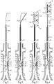
Fig. 1 is a schematic view of a medical device disembedding procedure in the early stages of the process; -
Fig. 2 is a schematic view similar toFig. 1 except later in the disembedding process; -
Fig. 3 is a schematic view similar to that ofFigs. 1 and 2 also showing an ultrasonic medical dissector according to the present disclosure; -
Fig. 4 is a schematic view similar toFigs. 1-3 after the ultrasonic medical dissector has disembedded a capture end of a vena cava filter according to one aspect of the present disclosure; -
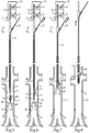
Fig. 5 is a schematic view of the medical device assembly in the early stages of a retrieval process; -
Fig. 6 is a schematic view similar toFig. 5 except later in the retrieval process according to one aspect of the present disclosure; -
Fig. 7 is a schematic view of the medical device assembly after the implantable device has become disembedded; -
Fig. 8 is a schematic view similar toFigs. 1-3 showing the implantable device being moved away from the embedding site. - Referring initially to
Figs. 1-4 , an ultrasonic medical dissector for disembedding ablood filter 42 whosecapture end 44 has become embedded insoft tissue 12 is illustrated. In some instances, an inferiorvena cava filter 42 can become tilted in ablood vessel 10, which is shown as theinferior vena cava 11, such that the capturedend 44 becomes embedded insoft tissue 12. The present disclosure teaches a new strategy for dissecting thecapture end 44 out of thesoft tissue 12 so that thefilter 42 may be retrieved or moved in a conventional manner. The process begins at -
Fig. 1 where awire 70 is slid through acatheter 80, which may be received in asheath 60. Anend 72 ofwire 70 is passed through thespace 16 that is defined betweenfilter 41 and thewall 13 ofblood vessel 10. Thereafter, as shown inFig. 2 , asnare 55 may be used to captureend 72 with aloop 56 ofsnare 55. Thereafter, theend 72 is pulled back up throughcatheter 80 utilizingsnare 55 so that bothends 71 and 72 are located out of the proximal end ofcatheter 80 leaving acutting loop 73 looped throughspace 16 as shown inFig. 3 . When in the configuration shown inFigure 3 , an ultrasonicmedical dissector 21 can be assembled using avibration generator 30 andwire 70. Thewire 70 defines acutting loop 73 that is remote from a first end 71 and asecond end 72. Thewire 70 is coupled to thevibration generator 30 in a cutting configuration as shown inFig. 3 . Thewire 70 includes acutting surface 74 that is located on an inner curvature 75 of thecutting loop 73. At least one of theends 71 and 72 ofwire 70 are connected to thevibration generator 30.Vibration generator 30 may include apiezo stack 32 housed in ahandle 31 that includes anactivation switch 34. When thevibration generator 30 is turned on, an ultra-sonic vibration generated may be transmitted to thecutting loop 73 by thewire 70 when thewire 70 is in tension. Thus, as shown inFig. 4 , when thevibration generator 30 is turned on to produce avibration 25, thewire 70 may be placed in tension so that thecutting loop 73 slides along, and may be guided by, anouter surface 46 to cut theend 44 out of thesoft tissue 12 in which it has become embedded. Thus, the ultrasonicmedical dissector 21 may utilize theouter surface 46 of thefilter 41 as acutting guide 45 when thecutting loop 73 is maneuvered to liberate theend 44. - The ultrasonic
medical dissector 21 may include acatheter 80 that is positioned between thevibration generator 30 and thecutting loop 73. At least onesegment 78 of the wire adjacent thecutting loop 73 is received in thecatheter 80.Fig. 3 shows the ultrasonic medical dissector in a cutting configuration. The ultrasonicmedical dissector 21 may also have a pre-cutting configuration in which at least one segment of thewire 70 is de-coupled from thevibration generator 30. - After the
end 44 offilter 42 has been freed from thevessel wall 13 as shown inFig. 4 , the inferiorvena cava filter 42 may be retrieved using known techniques, such as a snare that capturesend 44 along with a sheath for receiving the capturedblood filter 42. However,Figs. 1-4 show a circumstance in which both thetilted end 44 of theblood filter 42 has become embedded insoft tissue 12 but also one of thelegs 43 has become embedded in the vessel wall. According to the present disclosure, after theend 44 has been cut free of thevessel wall 13 as shown inFig. 4 , a different technique using avibration generator 30 may be utilized to complete the liberation offilter 42 by disembedding theleg 43 from thevessel wall 13 as discussed infra. - Referring now to
Figs. 5-8 , amedical device assembly 20 includes avibration generator 30, which may be suitable for generating ultrasonic vibrations in a manner known in the art. This aspect of the disclosure is apt when one or more of thelegs 43 of thefilter 42 are also embedded in soft tissue, after thecapture end 44 has been cut free. As discussed earlier,vibration generator 30 includes apiezo stack actuator 32 positioned in ahandle 31.Vibration generator 30 may also include anactivation switch 34, avibration frequency controller 33 and maybe avibration magnitude controller 35. In the illustrated embodiment,vibration generator 30 used withmedical device assembly 20 is shown identical to thevibration generator 30 used as part of the ultrasonicmedical dissector 21 ofFigs. 1-4 . Nevertheless, thevibration generators 30 for the ultrasonic medical dissector 21 (Figs. 1-4 ) and the medical device assembly 20 (Figs. 5-8 ) could be completely different devices without departing from the intended scope of the present disclosure.Medical device assembly 20 also includes animplantable device 40 that is shaped for temporary or permanent implantation in ablood vessel 10. In the illustrated embodiment,implantable device 40 takes the form of an inferiorvena cava filter 42. Nevertheless,implantable device 40 could be another type of filter, a stent, graft or maybe even a pacemaker lead, or any other known implantable device that is shaped for temporary or permanent implantation in a blood vessel without departing from the present disclosure.Medical device assembly 20 also includes avibration transmission apparatus 50 with oneend 51 coupled to thevibration generator 30, and anopposite end 52 in contact with the implantable device 40 (Fig. 6 ). Themedical device assembly 20 can be utilized to assist in disembedding the implanteddevice 40 from soft tissue by causing features of the implanted device (e.g. filter legs 43) to vibrate and act locally like an ultrasonic knife to assist in vibrating the implanteddevice 40 out of the soft tissue in which it is embedded. As used in this disclosure, "coupling" can be as simple as contact or as complex as a simultaneous push/pull connection facilitated by asnare 55 andcannula 54. - In the illustrated embodiment, the
vibration transmission apparatus 50 includes acannula 54 and atension member 53, which may take the form of asnare 55 with aloop 56 snared to theend 44 of the inferiorvena cava filter 42. In the illustrated embodiment, at least oneleg 43 of the inferiorvena cava filter 42 has become embedded insoft tissue 12 in thewall 13 of theinferior vena cava 11. After snaringend 44, thecannula 54 may be advanced into contact with the inferiorvena cava filter 42 as shown inFig. 6 . While maintaining some tension via thesnare 55, thevibration generator 30 may be turned on as shown inFig 7 . When this occurs, leg(s) 43 of the inferiorvena cava filter 42 will vibrate responsive to a vibration transmitted from thevibration generator 30 to thefilter 42. As a result, the filter may rapidly free itself, or at least become freed with a reduced pulling force, from being embedded in the soft tissue of theblood vessel 10, and permit aconventional retrieval sheath 60 to be advanced over thefilter 42 and allow the same to be removed from the patient's body as shown inFig.8 . - Although not necessary, the
vibration 25 may include a predetermined frequency that is correlated to a frequency response property of theimplantable device 40 or the tissue, or both. In some instances, it may be advantageous to utilize a vibration frequency that can excite one or more natural frequencies of theimplantable device 40. Furthermore, lab testing could allow for identification of certain frequencies that may be best suited for individual known implanted devices. For instance, one frequency may work well for a Tulip type filter, whereas another frequency may perform better for a Celect™ or a Greenfield™ filter. Accordingly, thevibration frequency controller 33 may be marked with different filter types instead of with numerical frequency selections without departing from the scope of the present disclosure. In such a way, the physician need only determine the type of filter implanted in the patient and then adjust the vibration generator to the frequency best suited for disembedding that particular filter type. - The present disclosure finds general applicability to disembedding, and possibly retrieving, implantable medical devices from a patient. The present disclosure finds specific applicability to disembedding and retrieving embedded inferior vena cava filters. The present disclosure also finds specific applicability to disembedding blood filters that are tilted so that the capture end has become embedded in the soft tissue of the vessel wall.
- Referring again to
Figs. 1-4 , a method of disembedding a medical device such as a blood filter that is embedded in soft tissue at asite 15 is illustrated. The process begins by threading afirst end 72 of awire 70 through aspace 16 that has a closed perimeter defined by thevessel wall 13 and the embedded medical device, which is avena cava filter 42 in the illustrations. This portion of the procedure is shown inFig. 1 . Next, theend 72 ofwire 70 may be snared with asnare 55 shown inFig. 2 . Thesnare 55 may then be used to moveend 72 ofwire 70 toward thevibration generator 30. This results in acutting loop 73 being trapped in thespace 16 as best shown inFig. 3 . Thus, the portion of the process shown inFigs. 1 and 2 effectively positions cuttingloop 73 ofwire 70 in thespace 16 between theblood filter 42 and thevessel wall 13. - The
wire 70 may be coupled to thevibration generator 30 by connecting a segment, which terminates at one of the first end 71 and thesecond end 72, to thehandle 31 ofvibration generator 30. Alternatively, only oneend 71 or 72 of wire need be coupled withvibration generator 30 provided that the opposite end of the wire is held in a fixed position so that movement ofvibration generator 30 can apply tension to thewire 70 in general, and the cuttingloop 73 in particular. After the ultrasonicmedical dissector 21 is configured as shown inFig. 3 , thevibration generator 30 may be turned on while applying tension towire 70. This tension will facilitate transmitting thevibration 25 from thepiezo stack 32 alongwire 70 to the cuttingloop 73. Theblood filter 42 may then be dissected from thesoft tissue 12 at least in part by vibrating the cuttingloop 73 with thevibration 25 from thevibration generator 30 while pulling a cuttingsurface 74 on a inner curvature 75 of the cuttingloop 73 through thesoft tissue 12. This cutting procedure may be guided by movement of the cuttingloop 73 through thesoft tissue 12 while being guided on anouter surface 46 ofblood filter 42. After theend 44 ofblood filter 42 has been cut free fromvessel wall 13, the ultrasonicmedical dissector 21 may be withdrawn fromsheath 60. If no other portion, such as aleg 43, is embedded in thevessel wall 13, the nowfree blood filter 42 may be retrieved in a conventional manner using asnare 55 and aretrieval sheath 60. However, in the illustrated embodiment, even after theend 44 has been cut free of thevessel wall 13, aleg 43 of theblood filter 43 is shown as itself being embedded in thevessel wall 13. In such a case, another vibration strategy may be utilized to liberate theleg 43 from thevessel wall 13 to facilitate retrieval in a conventional manner using asnare 55 and aretrieval sheath 60. - Referring again to
Figs. 5-8 , a method of retrieving an implanted device 40 (filter 42) that is partially embedded insoft tissue 12 at asite 15 includes coupling avibration transmission apparatus 50 to the implanteddevice 40. In the illustrated embodiment, in the case of a embedded inferiorvena cava filter 42, the process may begin by grasping the nowfree end 44 of thefilter 42 with aloop 56 of asnare 55. Next, acannula 54 is slid along thesnare 55 into contact withfilter 42 as shown inFigs. 2 and 3 . Thefilter 42 is then disembedded from thesoft tissue 12 at least in part by generating avibration 25 with thevibration generator 30 while gently pulling on thesnare 55. Thevibration 25 is transmitted along thevibration transmission apparatus filter 42 to cause the implanteddevice 40 to vibrate. This may be accomplished aftercannula 54 has been advanced into contact with thefilter 42. Asnare 55 may be placed in tension while the vibration is transmitted so that when thefilter 42 begins to vibrate there is a slight pulling force to help withdraw the same from thesoft tissue 12. After becoming disembedded, the implanteddevice 40 may be moved away from thesite 15, such as by pulling thefilter 42 from outside of asheath 60 into thesheath 60 for removal from the patient's body. In the illustrated embodiment, thecannula 54 is in contact with, but not attached to, thedistal end 44 of the inferiorvena cava filter 42. The distal end of thecannula 54 may be in contact with one or more of thelegs 43 of thefilter 42.Cannula 54 should be sufficiently rigid that a vibration generated byvibration generator 30 can successfully be transmitted without becoming overly damped before arriving at thefilter 42 that is embedded in thesoft tissue 12. In the illustrated embodiment, the end of thefilter 42 may actually be received into thecannula 44 when thevibration 25 is transmitted. In some instances, it may be useful to change at least one of a vibration's magnitude and a vibration frequency in order to successfully disembed the implanted device from the surroundingsoft tissue 12. - Current vena cava filter retrieval methods can involve significant force or complex cutting, and are high risk for a patient. The present disclosure provides a method of filter retrieval that can minimize tissue damage and reduce patient risk, while also providing a significantly faster procedure than current retrieval methods, and with considerably less pulling force.
- The present description is for illustrative purposes only, and should not be construed to narrow the breadth of the present disclosure in any way. For instance, although the method(s) is disclosed in the context of a live body, the disclosed method(s) could also be performed on artificial tissue to demonstrate the technique without a live body, such as for teaching purposes. Thus, those skilled in the art will appreciate that various modifications might be made to the presently disclosed embodiments without departing from the full and fair scope and spirit of the present disclosure. Other aspects, features and advantages will be apparent upon an examination of the attached drawings and appended claims.
- The following numbered clauses set out further important features of the disclosure:
- 1. A method of disembedding a medical device that is embedded in soft tissue at a site, comprising the steps of:
- positioning a cutting loop of a wire in a space between the medical device and a vessel wall;
- coupling the wire to a vibration generator remote from the cutting loop;
- disembedding the medical device at least in part by vibrating the cutting loop with a vibration from the vibration generator while pulling a cutting surface on an inner curvature of the cutting loop through the soft tissue; and
- moving the medical device away from the site.
- 2. The method of clause 1 wherein the positioning step includes threading a first end of the wire through a space with a closed perimeter defined by the vessel wall and the medical device.
- 3. The method of any of clauses 1-2 wherein the positioning step includes snaring the first end of the wire with a snare; and
moving the first end of the wire toward the vibration generator with the snare. - 4. The method of any of clauses 1-3 wherein the coupling step includes connecting a segment of the wire that terminates at the first end to a handle of the vibration generator.
- 5. The method of any of clauses 1-4 wherein the disembedding step includes tensioning the wire; and
transmitting the vibration from the vibration generator to the cutting loop through the tensioned wire. - 6. The method of any of clauses 1-5 wherein the disembedding step includes guiding movement of the cutting loop through the soft tissue with an outer surface of the medical device.
- 7. The method of any of clauses 1-6 wherein the medical device is a blood filter; and
the outer surface includes an outer surface of a leg of the blood filter. - 8. The method of any of clauses 1-7 wherein the positioning step includes threading a first end of the wire through a space with a closed perimeter defined by the vessel wall and the blood filter.
- 9. The method of any of clauses 1-8 wherein the disembedding step includes tensioning the wire; and
transmitting the vibration from the vibration generator to the cutting loop through the tensioned wire. - 10. The method of any of clauses 1-9 wherein the moving step includes moving at least a portion of the blood filter into a retrieval sheath.
Claims (12)
- An ultrasonic medical dissector comprising:a vibration generator;a wire defining a cutting loop remote from a first end and a second end, and the wire being coupled to the vibration generator in a cutting configuration, and a cutting surface of the cutting loop being located on an inner curvature of the cutting loop;wherein a vibration generated by the vibration generator is transmitted to the cutting loop by the wire when the wire is in tension.
- The ultrasonic medical dissector of claim 1 having a pre-cutting configuration in which at least one segment of the wire is decoupled from the vibration generator.
- The ultrasonic medical dissector of any preceding claim including a catheter positioned between the vibration generator and the cutting loop;
at least one segment of the wire adjacent the cutting loop is received in the catheter. - The ultrasonic medical dissector of any preceding claim including a cutting guide that is located adjacent the cutting loop.
- The ultrasonic medical dissector of any preceding claim wherein the cutting guide is an outer surface of a blood filter.
- The ultrasonic medical dissector of any preceding claim wherein the blood filter is an inferior vena cava filter.
- The ultrasonic medical dissector of any preceding claim wherein the vibration generator includes a piezo stack positioned in a handle.
- The ultrasonic medical dissector of any preceding claim including a cutting guide that is located adjacent the cutting loop; and
the cutting guide includes an outer surface of a blood filter. - The ultrasonic medical dissector of any preceding claim having a pre-cutting configuration in which at least one segment of the wire is decoupled from the vibration generator.
- The ultrasonic medical dissector of any preceding claim including a catheter positioned between the vibration generator and the cutting loop;
at least one segment of the wire adjacent the cutting loop is received in the catheter. - The ultrasonic medical dissector of any preceding claim wherein the vibration generator has a plurality of discrete vibration frequencies and means enabling an operator to select one of said frequencies.
- The combination of a blood filter or other implantable medical device having a resonant frequency of vibration with the ultrasonic medical dissector of any preceding claim wherein the vibration generator has a discrete vibration frequency corresponding to said resonant frequency of vibration of the medical device.
Applications Claiming Priority (1)
| Application Number | Priority Date | Filing Date | Title |
|---|---|---|---|
| US201662373614P | 2016-08-11 | 2016-08-11 |
Publications (1)
| Publication Number | Publication Date |
|---|---|
| EP3281590A1 true EP3281590A1 (en) | 2018-02-14 |
Family
ID=59399335
Family Applications (1)
| Application Number | Title | Priority Date | Filing Date |
|---|---|---|---|
| EP17183030.0A Withdrawn EP3281590A1 (en) | 2016-08-11 | 2017-07-25 | Ultra-sonic medical dissector |
Country Status (2)
| Country | Link |
|---|---|
| US (1) | US10758260B2 (en) |
| EP (1) | EP3281590A1 (en) |
Families Citing this family (2)
| Publication number | Priority date | Publication date | Assignee | Title |
|---|---|---|---|---|
| CN112074242B (en) | 2018-05-03 | 2024-06-28 | 美敦力瓦斯科尔勒公司 | Tip assembly, system and method for fragmenting the frame of a deployed prosthesis |
| US20260165881A1 (en) * | 2024-12-16 | 2026-06-18 | Alcon Inc. | Ultrasonic capsulorhexis instrument |
Citations (7)
| Publication number | Priority date | Publication date | Assignee | Title |
|---|---|---|---|---|
| US6231578B1 (en) * | 1998-08-05 | 2001-05-15 | United States Surgical Corporation | Ultrasonic snare for excising tissue |
| US6383194B1 (en) * | 2001-02-26 | 2002-05-07 | Viswanadham Pothula | Flexible ultrasonic surgical snare |
| US20060095046A1 (en) * | 2004-11-01 | 2006-05-04 | Sdgi Holdings, Inc. | Devices and methods for explantation of intervertebral disc implants |
| EP2005912A2 (en) * | 2006-03-09 | 2008-12-24 | Olympus Medical Systems Corp. | Treatment instrument for endoscope |
| US20130150695A1 (en) * | 2011-12-08 | 2013-06-13 | Biotronik Se & Co. Kg | Medical Implant and Medical Arrangement |
| US20140277087A1 (en) * | 2013-03-14 | 2014-09-18 | Cook Medical Technologies Llc | Spiral vena cava filter removal device |
| US9301828B1 (en) * | 2013-03-14 | 2016-04-05 | Matt D. Pursley | Multi lumen IVC filter retrieval device |
Family Cites Families (6)
| Publication number | Priority date | Publication date | Assignee | Title |
|---|---|---|---|---|
| US4854325A (en) | 1987-11-09 | 1989-08-08 | Stevens Robert C | Reciprocating guidewire method |
| US5427118A (en) | 1993-10-04 | 1995-06-27 | Baxter International Inc. | Ultrasonic guidewire |
| CA2213948C (en) | 1996-09-19 | 2006-06-06 | United States Surgical Corporation | Ultrasonic dissector |
| US5908395A (en) | 1997-03-17 | 1999-06-01 | Advanced Cardiovascular Systems, Inc. | Vibrating guidewire |
| US6514267B2 (en) | 2001-03-26 | 2003-02-04 | Iep Pharmaceutical Devices Inc. | Ultrasonic scalpel |
| US20120184987A1 (en) * | 2009-10-08 | 2012-07-19 | Cook Medical Technologies Llc | Vascular Implant Retrieval Method, Retrieval Assembly And Tool For Same |
-
2017
- 2017-05-18 US US15/598,419 patent/US10758260B2/en active Active
- 2017-07-25 EP EP17183030.0A patent/EP3281590A1/en not_active Withdrawn
Patent Citations (8)
| Publication number | Priority date | Publication date | Assignee | Title |
|---|---|---|---|---|
| US6231578B1 (en) * | 1998-08-05 | 2001-05-15 | United States Surgical Corporation | Ultrasonic snare for excising tissue |
| US6383194B1 (en) * | 2001-02-26 | 2002-05-07 | Viswanadham Pothula | Flexible ultrasonic surgical snare |
| US20060095046A1 (en) * | 2004-11-01 | 2006-05-04 | Sdgi Holdings, Inc. | Devices and methods for explantation of intervertebral disc implants |
| EP2005912A2 (en) * | 2006-03-09 | 2008-12-24 | Olympus Medical Systems Corp. | Treatment instrument for endoscope |
| EP2005912B1 (en) * | 2006-03-09 | 2016-05-04 | Olympus Corporation | Treatment instrument for endoscope |
| US20130150695A1 (en) * | 2011-12-08 | 2013-06-13 | Biotronik Se & Co. Kg | Medical Implant and Medical Arrangement |
| US20140277087A1 (en) * | 2013-03-14 | 2014-09-18 | Cook Medical Technologies Llc | Spiral vena cava filter removal device |
| US9301828B1 (en) * | 2013-03-14 | 2016-04-05 | Matt D. Pursley | Multi lumen IVC filter retrieval device |
Also Published As
| Publication number | Publication date |
|---|---|
| US20180042635A1 (en) | 2018-02-15 |
| US10758260B2 (en) | 2020-09-01 |
Similar Documents
| Publication | Publication Date | Title |
|---|---|---|
| US10729415B2 (en) | Vibrating medical device assembly and method of retrieving embedded implantable device | |
| JP7113099B2 (en) | Devices and methods for lenticular tissue removal | |
| US5374273A (en) | Method for retrieval of retained common bile duct stones | |
| US6699256B1 (en) | Medical grafting apparatus and methods | |
| US10265062B2 (en) | Surgical instrument for manipulating and passing suture | |
| US8025668B2 (en) | Medical device removal system | |
| US8114102B2 (en) | Temporary hemostatic plug apparatus and method of use | |
| US9936941B2 (en) | Surgical instrument for manipulating and passing suture | |
| KR101437253B1 (en) | Follicular unit removal tool with pivoting retention member | |
| EP2839796A1 (en) | Endovascular delivery system for magnetic compression vascular anastomosis | |
| US20030120291A1 (en) | Temporary seal and method for facilitating anastomosis | |
| EP3355803B1 (en) | Vascular closure device | |
| EP2544603A1 (en) | Obstruction removal assembly | |
| JP2003535638A (en) | Equipment for removing objects from the patient's body | |
| WO2012021866A2 (en) | Systems and methods for harvesting follicular units | |
| US10758260B2 (en) | Ultra-sonic medical dissector and method of disembedding a medical device from soft tissue | |
| JP2005021576A (en) | Endoscopic magnetic anchor remote guidance system and endoscopic treatment method using magnetic anchor remote guidance system | |
| RU2013119074A (en) | DEVICE AND METHODS OF ITS USE DURING ARTHROSCOPIC OPERATION | |
| JPWO2016027529A1 (en) | Tissue grasping device | |
| JP2017035478A (en) | Methods, systems, and devices for surgical suturing | |
| AU2021244114A1 (en) | Syndesmosis insertion construct | |
| US20030163143A1 (en) | Apparatus and method for suturing in restricted space | |
| US9592079B1 (en) | Device and method for assisting removal of items endovascularly | |
| EP1972283B1 (en) | Tissue lifting system, and indwelling tool | |
| US10092386B1 (en) | Multi lumen IVC filter retrieval device |
Legal Events
| Date | Code | Title | Description |
|---|---|---|---|
| PUAI | Public reference made under article 153(3) epc to a published international application that has entered the european phase |
Free format text: ORIGINAL CODE: 0009012 |
|
| STAA | Information on the status of an ep patent application or granted ep patent |
Free format text: STATUS: THE APPLICATION HAS BEEN PUBLISHED |
|
| AK | Designated contracting states |
Kind code of ref document: A1 Designated state(s): AL AT BE BG CH CY CZ DE DK EE ES FI FR GB GR HR HU IE IS IT LI LT LU LV MC MK MT NL NO PL PT RO RS SE SI SK SM TR |
|
| AX | Request for extension of the european patent |
Extension state: BA ME |
|
| STAA | Information on the status of an ep patent application or granted ep patent |
Free format text: STATUS: REQUEST FOR EXAMINATION WAS MADE |
|
| 17P | Request for examination filed |
Effective date: 20180810 |
|
| RBV | Designated contracting states (corrected) |
Designated state(s): AL AT BE BG CH CY CZ DE DK EE ES FI FR GB GR HR HU IE IS IT LI LT LU LV MC MK MT NL NO PL PT RO RS SE SI SK SM TR |
|
| STAA | Information on the status of an ep patent application or granted ep patent |
Free format text: STATUS: EXAMINATION IS IN PROGRESS |
|
| 17Q | First examination report despatched |
Effective date: 20210617 |
|
| GRAP | Despatch of communication of intention to grant a patent |
Free format text: ORIGINAL CODE: EPIDOSNIGR1 |
|
| STAA | Information on the status of an ep patent application or granted ep patent |
Free format text: STATUS: GRANT OF PATENT IS INTENDED |
|
| INTG | Intention to grant announced |
Effective date: 20240122 |
|
| RIN1 | Information on inventor provided before grant (corrected) |
Inventor name: KRIEGER, JOSHUA F. Inventor name: ROEDER, REBECCA |
|
| STAA | Information on the status of an ep patent application or granted ep patent |
Free format text: STATUS: THE APPLICATION IS DEEMED TO BE WITHDRAWN |
|
| 18D | Application deemed to be withdrawn |
Effective date: 20240523 |