EP3280924B1 - Pedestal bearing housing and associated bearing assembly - Google Patents
Pedestal bearing housing and associated bearing assembly Download PDFInfo
- Publication number
- EP3280924B1 EP3280924B1 EP15714841.2A EP15714841A EP3280924B1 EP 3280924 B1 EP3280924 B1 EP 3280924B1 EP 15714841 A EP15714841 A EP 15714841A EP 3280924 B1 EP3280924 B1 EP 3280924B1
- Authority
- EP
- European Patent Office
- Prior art keywords
- pedestal
- walls
- plane
- bearing housing
- flange portions
- Prior art date
- Legal status (The legal status is an assumption and is not a legal conclusion. Google has not performed a legal analysis and makes no representation as to the accuracy of the status listed.)
- Active
Links
Images


Classifications
-
- F—MECHANICAL ENGINEERING; LIGHTING; HEATING; WEAPONS; BLASTING
- F16—ENGINEERING ELEMENTS AND UNITS; GENERAL MEASURES FOR PRODUCING AND MAINTAINING EFFECTIVE FUNCTIONING OF MACHINES OR INSTALLATIONS; THERMAL INSULATION IN GENERAL
- F16C—SHAFTS; FLEXIBLE SHAFTS; ELEMENTS OR CRANKSHAFT MECHANISMS; ROTARY BODIES OTHER THAN GEARING ELEMENTS; BEARINGS
- F16C35/00—Rigid support of bearing units; Housings, e.g. caps, covers
- F16C35/04—Rigid support of bearing units; Housings, e.g. caps, covers in the case of ball or roller bearings
- F16C35/042—Housings for rolling element bearings for rotary movement
- F16C35/047—Housings for rolling element bearings for rotary movement with a base plate substantially parallel to the axis of rotation, e.g. horizontally mounted pillow blocks
-
- F—MECHANICAL ENGINEERING; LIGHTING; HEATING; WEAPONS; BLASTING
- F16—ENGINEERING ELEMENTS AND UNITS; GENERAL MEASURES FOR PRODUCING AND MAINTAINING EFFECTIVE FUNCTIONING OF MACHINES OR INSTALLATIONS; THERMAL INSULATION IN GENERAL
- F16C—SHAFTS; FLEXIBLE SHAFTS; ELEMENTS OR CRANKSHAFT MECHANISMS; ROTARY BODIES OTHER THAN GEARING ELEMENTS; BEARINGS
- F16C19/00—Bearings with rolling contact, for exclusively rotary movement
- F16C19/22—Bearings with rolling contact, for exclusively rotary movement with bearing rollers essentially of the same size in one or more circular rows, e.g. needle bearings
- F16C19/34—Bearings with rolling contact, for exclusively rotary movement with bearing rollers essentially of the same size in one or more circular rows, e.g. needle bearings for both radial and axial load
- F16C19/38—Bearings with rolling contact, for exclusively rotary movement with bearing rollers essentially of the same size in one or more circular rows, e.g. needle bearings for both radial and axial load with two or more rows of rollers
-
- F—MECHANICAL ENGINEERING; LIGHTING; HEATING; WEAPONS; BLASTING
- F16—ENGINEERING ELEMENTS AND UNITS; GENERAL MEASURES FOR PRODUCING AND MAINTAINING EFFECTIVE FUNCTIONING OF MACHINES OR INSTALLATIONS; THERMAL INSULATION IN GENERAL
- F16C—SHAFTS; FLEXIBLE SHAFTS; ELEMENTS OR CRANKSHAFT MECHANISMS; ROTARY BODIES OTHER THAN GEARING ELEMENTS; BEARINGS
- F16C2204/00—Metallic materials; Alloys
- F16C2204/60—Ferrous alloys, e.g. steel alloys
-
- F—MECHANICAL ENGINEERING; LIGHTING; HEATING; WEAPONS; BLASTING
- F16—ENGINEERING ELEMENTS AND UNITS; GENERAL MEASURES FOR PRODUCING AND MAINTAINING EFFECTIVE FUNCTIONING OF MACHINES OR INSTALLATIONS; THERMAL INSULATION IN GENERAL
- F16C—SHAFTS; FLEXIBLE SHAFTS; ELEMENTS OR CRANKSHAFT MECHANISMS; ROTARY BODIES OTHER THAN GEARING ELEMENTS; BEARINGS
- F16C23/00—Bearings for exclusively rotary movement adjustable for aligning or positioning
- F16C23/06—Ball or roller bearings
- F16C23/08—Ball or roller bearings self-adjusting
- F16C23/082—Ball or roller bearings self-adjusting by means of at least one substantially spherical surface
- F16C23/086—Ball or roller bearings self-adjusting by means of at least one substantially spherical surface forming a track for rolling elements
Definitions
- the present invention relates to a pedestal bearing housing for accommodating a bearing, and to a bearing assembly including such a pedestal bearing housing and a bearing accommodated in the pedestal bearing housing.
- Bearing assemblies for guiding a shaft usually include a bearing received in a housing.
- the bearing can be of any type, e.g. a plain bearing or a roller bearing with rolling bodies of various shapes, including balls, needles, cylindrical rollers, barrel rollers, tapered rollers and spherical rollers.
- the pedestal bearing housing is an intermediate stationary part, which supports the rotating part and can be fixed to a support structure, e.g. a planar base.
- the pedestal bearing housings can be subjected to relatively high dynamic stress at frequencies that can vary considerably with the rotation speed of the shaft. These stresses should be not result in vibration of the pedestal bearing housing, which would be transmitted to the bearing and to the shaft or to the base.
- the pedestal bearing housing should have a high stiffness.
- the pedestal bearing housing should simultaneously minimise the amount of material used.
- a pedestal bearing housing comprising a substantially cylindrical bearing seat configured to receive a bearing, and a foot member adapted to support said bearing seat and having a generally planar lower surface formed by end surfaces of outer and inner supporting walls configured to be connected to an external support structure, wherein the inner supporting walls extend between the outer supporting walls forming cavities there between, wherein at least one of the inner supporting walls comprises at least one protrusion along its axial extension.
- the contact surface to the external support structure may be increased.
- the pedestal bearing housing may have an increased stiffness and thereby being able to distribute the forces emanating from the bearing during use in a more suitable manner.
- substantial deformations of the bearing seat and high stress zones in some parts of the pedestal bearing housing are still experienced, in particular when a radial load is applied in a direction at an angle with the plane of symmetry of the pedestal bearing housing.
- the pedestal bearing housing further comprises an intermediate portion that extends between the bearing seat and the support plane and between the two flange portions.
- the intermediate portion includes at least a median foot protruding from the bearing seat towards the support plane.
- the median foot provides a median support surface that lies in the support plane and is part of the planar support surface.
- the pedestal bearing housing is provided with four slanted inner reinforcing walls which form a cross and extend from one of the two intermediate outer transverse walls to the intermediate portion, away from the median foot.
- the invention aims to provide an improved pedestal housing structure that avoids or limits stress concentrations and weak points so that the pedestal bearing housing can sustain higher loads.
- a pedestal bearing housing comprising a bearing seat, two attachment flange portions extending between the bearing seat and a support plane, the two attachment flange portions protruding on opposite sides of a median longitudinal plane perpendicular to the support plane, each of the two attachment flange portions including an upper flange wall protruding away from the median longitudinal plane, an outer longitudinal supporting wall and an inner longitudinal supporting wall extending in a direction parallel to the median longitudinal plane, and two outer transverse supporting walls each extending from the outer longitudinal supporting wall to the inner longitudinal supporting wall, the outer longitudinal supporting wall, inner longitudinal supporting wall and outer transverse walls extending from the upper flange wall towards the support plane and having edges that lie in the support plane to form at least part of a planar support surface of the pedestal bearing housing, a flange cavity being provided between the upper flange wall, outer longitudinal supporting wall, inner longitudinal supporting wall, outer transverse walls and support plane, the upper flange wall being provided with at least one through hole which opens into the f
- the bearing seat defines a surface of revolution about a revolution axis, parallel to the support plane and contained in the median longitudinal plane, to receive a bearing.
- each of the two transverse ribs has a lower free edge that lies at a distance from the support plane.
- the lower free edge of each of the two transverse ribs has a concave cross-section in the transversal reference plane.
- the transverse ribs operate like arch-buttresses between the bearing seat and the inner longitudinal supporting walls.
- the pedestal bearing housing further comprises an intermediate portion that extends between the bearing seat and the support plane and between the two flange portions.
- the intermediate portion includes at least a median foot protruding from the bearing seat towards the support plane and having a median support surface that lies in the support plane and is part of the planar support surface, and each of the two ribs extends from the inner longitudinal supporting wall of the respective one of the two flange portions to the median foot.
- the median foot supports a substantial part of the radial load on the pedestal bearing housing. Moreover, part of the load transmitted by the bearing seat to the ribs is transferred to the median foot, which further limits the stress in the flange portions.
- each of the two transverse ribs has a convex intermediate portion, a concave end portion between the convex intermediate portion and the median foot and a concave end portion between the convex intermediate portion and the inner longitudinal supporting wall of the respective one of the two flange portions.
- the concave end portion between the convex intermediate portion and the inner longitudinal supporting wall is preferably at an angle of between 35° and 50° to the median longitudinal plane.
- the concave end portion between the convex intermediate portion and the median foot is preferably at an angle of between 3° and 10° to the median longitudinal plane.
- 3 ⁇ D 1 D 2 ⁇ 7 where:
- the intermediate portion further includes two intermediate outer transverse walls each extending from one of the flange portions to the other of the two flange portions.
- the intermediate outer transverse walls interconnect the two flange portions to avoid undesired deformation of the housing.
- Each of the two intermediate transverse walls can be parallel to, and preferably coplanar with, one of the two outer transverse walls of each of the two flange portions.
- the median foot lies between the two intermediate outer transverse walls.
- One or more intermediate cavities are provided between the intermediate outer transverse walls, and the inner longitudinal wall of each of the two flange portions.
- the pedestal of the housing is essentially hollow, which is particularly advantageous in terms of weight and quantity of material.
- the two intermediate outer transverse walls reinforce the overall structure of the pedestal and connect the two flange portions with one another.
- the two intermediate outer transverse walls extend from the bearing seat towards the support plane and have edges that lie in the support plane to form part of the planar support surface of the pedestal.
- the two intermediate outer transverse walls contribute to the transfer of the load to the base on which the pedestal housing is fixed.
- the intermediate portion further includes at least two inner reinforcing walls each extending from one of the two intermediate outer transverse walls to the median foot. This limits bending of the intermediate outer transverse walls.
- the at least two inner reinforcing walls extend from the bearing seat towards the support plane and have edges that lie in the support plane to form part of the planar support surface of the pedestal. The two inner reinforcing walls contribute to the transfer of the load to the base on which the pedestal housing is fixed.
- the at least two inner reinforcing walls include at least two walls perpendicular to the outer intermediate transverse walls.
- the at least two inner reinforcing walls include at least two slanted inner reinforcing walls each at an angle of between 30° and 60° to the outer intermediate transverse walls.
- the at least two inner reinforcing walls include at least four slanted inner reinforcing walls each at an angle of between 30° and 60° to the outer intermediate transverse walls and forming a cross. The cross between the intermediate outer transverse walls, combined with the inner and outer longitudinal walls, provides a very stiff structure.
- the bearing seat has two axial ends, located on each side and at equal distance of the transversal reference plane.
- the dynamic load applied to the bearing seat is maximal in a central part of the bearing seat and the deformations are also potentially greater in this region, and it particularly advantageous to provide the reinforcement of the ribs in this region.
- the transversal reference plane is closer to a first geometrical plane containing one of the two outer transverse walls of each of the two flange portions than to a second geometrical plane containing another one of the two outer transverse walls of each of the two flange portions.
- the pedestal bearing housing is made of ductile cast iron.
- the pedestal bearing housing comprises a cap and a pedestal, which comprises the pedestal flange portions, the cap and pedestal being fixed to one another, preferably by removable fastening elements such as bolts, the bearing seat formed by walls of the cap and pedestal.
- a bearing assembly comprising a pedestal bearing housing as described hereinbefore and at least one outer bearing ring fitted into the bearing seat.
- the outer bearing ring has a spherical race having a centre located in the transversal reference plane.
- the outer bearing ring has two end walls perpendicular at equal distance from the transversal reference plane.
- a bearing assembly 10 for guiding a rotating shaft 12 in rotation about a rotation axis 100 includes a bearing 14 fitted onto the shaft 12 and a pedestal bearing housing 16 for affixing the bearing assembly 1 to a planar surface of a base (not shown).
- the bearing 14 illustrated in the drawings is a spherical roller bearing which consists of a single outer ring 18 provided with a single spherical raceway 20, a single inner ring 22 provided with two spherical raceways 24, two rows of rolling bodies 26, in this case spherical rollers, and one or two cages 27 for guiding the rolling bodies 26.
- the inner ring 22 has a tapered inner face and is force-fitted onto the shaft 12 by means of a slit tapered sleeve 28 and of a nut 29.
- the outer ring 18 has two end faces 30 at equal distance of a centre of rotation O of the bearing and an external cylindrical face 32, which is press-fitted into a cylindrical bearing seat 34 provided in the pedestal bearing housing 16.
- the axial position of the outer ring 18 can be secured by one or two spacer rings 36, each inserted between one of the end faces 30 and an end shoulder 38 of the bearing seat 34 .
- the revolution axis 200 defined by the cylindrical bearing seat will be a reference axis for the entire description.
- the spherical roller bearing 14 allows a degree of rotation of the rotation axis 100 of the shaft about the centre of rotation O and the particular position illustrated in Fig. 1 , with the rotation axis 100 aligned with the revolution axis 200, is only one particular position.
- the section plane II-II of Fig. 2 is perpendicular to the revolution axis 200 and contains the centre of rotation O of the bearing. This transversal reference plane II-II is at equal distance from the two end faces 30 of the outer ring 18 and at equal distance of the shoulders 38 of the bearing seat 34.
- the pedestal bearing housing 16 is preferably made of ductile cast iron and consists of two parts, namely a cap 40 and a pedestal 42 fixed to one another by any convenient means, preferably by detachable fixing elements such as bolts 44.
- the bearing seat 34 is defined by internal surfaces of the cap 40 and pedestal 42.
- the pedestal 42 has a planar support surface 46, which lies in a support plane 300 parallel to the revolution axis, and is intended to rest on a planar face of a base or foundation.
- the median longitudinal plane I-I which contains the revolution axis 200 and is perpendicular to the support plane 300, is a plane of symmetry of the bearing seat 34.
- the pedestal 42 comprises two attachment flange portions 48 protruding on opposite sides of the median longitudinal plane I-I.
- each of the two attachment flange portions 48 includes an upper flange wall 50 protruding away from the median longitudinal plane I-I and substantially perpendicular to the median longitudinal plane I-I, an outer longitudinal supporting wall 52 and an inner longitudinal supporting wall 54 extending in a direction parallel to the median longitudinal plane I-I, and two outer transverse supporting walls 56 each extending between the outer longitudinal supporting wall 52 to the inner longitudinal supporting wall 54.
- the outer longitudinal supporting wall 52, inner longitudinal supporting wall 54 and outer transverse walls 56 extend from the upper flange wall 50 towards the support plane 300 and have edges that lie in the support plane to form parts of the planar support surface 46 of the pedestal.
- a flange cavity 58 is provided between the outer longitudinal supporting wall 52, upper flange wall 50, inner longitudinal supporting wall 54, outer transverse walls 56 and support plane 300.
- the upper flange wall 50 is provided with two through holes 60, which open into the flange cavity 58, each with a hole axis perpendicular to the support plane 300. These through holes 60 are suitable intended for inserting bolts or other fixing elements (not shown) for securing the bearing assembly 10 to a base or foundation.
- the pedestal further includes an intermediate portion 62 between the two flange portions 48.
- the intermediate portion 62 includes two intermediate outer transverse walls 64 each parallel or substantially coplanar with one of the two outer transverse walls 56 of each of the two flange portions 48, and four inner reinforcing walls 66 each extending from one of the two intermediate outer transverse walls 64 to a common median foot 68 to form a cross.
- the median foot is located at the intersection between the longitudinal median plane II-II and the transversal reference plane I-I, i.e. directly below the centre of rotation O of the bearing.
- the median foot 68 protrudes towards the support plane 300 and has a median support face that lies in the support plane and is part of the planar support surface 46.
- the four slanted inner reinforcing walls 66 are each at an angle of between 30° and 60° to the outer intermediate transverse walls 64 (i.e. two adjacent inner reinforcing walls 66 are at an angle of between 60° and 120° with one another).
- the intermediate outer transverse walls 64 and inner reinforcing walls 66 extend from the bearing seat 34 towards the support plane 300 and have edges that lie in the support plane 300 to form part of the planar support surface 46 of the pedestal 42.
- Intermediate cavities 70 are formed between the intermediate outer transverse walls 64, the inner longitudinal wall 54 of each of the two flange portions 48, and the inner reinforcing walls 66.
- the bearing 14 is slightly offset in the axial direction with respect to the bearing housing.
- the transversal reference plane II-II is offset with respect to the pedestal, i.e. it is closer to one of the two outer transverse walls 56 of each of the two flange portions 48 than to the other one of the two outer transverse walls 56 of each of the two flange portions 48.
- the pedestal bearing housing 16 further comprises two transverse ribs 72 each extending in the transversal reference plane II-II from the bearing seat 34 to the inner longitudinal supporting wall 54 of a respective one of the two flange portions 48. More specifically, each of the two ribs 72 extends from the inner longitudinal supporting wall 54 of the respective one of the two flange portions 48 to the median foot 68. Each of the two transverse ribs 72 has a lower free edge 74 that lies at a distance from the support plane 300. As shown in Fig.
- the lower free edge 74 of each of the two transverse ribs has a curved cross-section in the transversal reference plane II-II with a convex intermediate portion 74.1 between to concave end 74.2, 74.3 portions, which reach the support plane 300 preferably at an angle of more than 45°.
- the maximal distance D1 between the support plane 300 and the free edge 74 is found in the concave portion 74.2.
- the minimal distance D2 between the convex intermediate portion 74.1 and the support plane 300 is found in a transition zone between the convex intermediate portion 74.1 and the concave end portion 74.3.
- the ration D1/D2 is between 3 and 7.
- the two transverse ribs 72 are effective to transfer load from the bearing seat 34 to the inner longitudinal walls 54, without substantially increasing the stress in the region of the upper flange wall 50 and of the through holes 60. Hence, the stress, which would be too high in the region of the upper flange wall 50 without the transverse ribs 72, lies within limits that ensure an indefinite operating life to the pedestal housing.
- Each transverse rib 72 spans an angle A1, measured in the transversal reference plane II-II from the median longitudinal plane I-I to the inner longitudinal supporting wall 54, of preferably more than 35° and less than 55°, in the present case of approximately 43°.
- the median foot 68 spans and angle A2, measured in the transversal reference plane II-II from the median longitudinal plane I-I to the inner longitudinal beginning of the transverse rib 72, of preferably more than 3° but less than 10°, in the illustrated embodiment about 3,5°.
- the median longitudinal plane I-I is a plane of symmetry for the planar support surface 46 of the pedestal 42 and for the transverse ribs 72, and preferably for the outer longitudinal supporting walls 52, inner longitudinal supporting walls 54, upper flange walls 50 and preferably for the outer transverse walls 56, intermediate outer transverse walls 64 and inner reinforcing walls 66.
- the slanted inner reinforcing walls are omitted and the arched transverse ribs 72 extend from the bearing seat 34 to the inner longitudinal supporting wall 54 of the respective one of the two flange portions 48 and to the median foot 68, which protrudes towards the support plane 300 and has a median support surface that lies in the support plane and is part of the planar support surface 46.
- the transverse reference plane II-II can be at mid-distance of the two outer transverse walls 56 of each flange portions 48.
- the intermediate outer transverse walls 64 can be dispensed with, or can have a free edge that remains at a distance from the support plane 300, in which case they operate like bridges between the two flange portions 48 without transmitting load to the base to which the pedestal is fixed.
- the bearing housing 16 can be made in one piece, or in more than two parts, in any suitable material, including e.g. grey cast iron, ductile cast iron, or cast aluminium.
- the bearing 14 can be of any type, including spherical and non-spherical bearings, plain bearings and rolling bearings with rolling bodies 26 of any kind, including tapered, cylindrical, barrel or spherical rollers, balls and needles or combinations thereof, with one or more rows of rolling bodies, one or more outer rings and one or more inner rings.
- the inner ring can be force-fitted or otherwise fixed onto the shaft by any means.
- the outer ring can be omitted, in which case the bearing seat 34 is a bearing raceway or, if the bearing is a slide bearing, a slide bearing surface.
- the bearing seat 34 can have a cylindrical shape, a stepped cylindrical shape, a conical shape, with or without splines.
Landscapes
- Engineering & Computer Science (AREA)
- General Engineering & Computer Science (AREA)
- Mechanical Engineering (AREA)
- Mounting Of Bearings Or Others (AREA)
Description
- The present invention relates to a pedestal bearing housing for accommodating a bearing, and to a bearing assembly including such a pedestal bearing housing and a bearing accommodated in the pedestal bearing housing.
- Bearing assemblies for guiding a shaft usually include a bearing received in a housing. The bearing can be of any type, e.g. a plain bearing or a roller bearing with rolling bodies of various shapes, including balls, needles, cylindrical rollers, barrel rollers, tapered rollers and spherical rollers. The pedestal bearing housing is an intermediate stationary part, which supports the rotating part and can be fixed to a support structure, e.g. a planar base. The pedestal bearing housings can be subjected to relatively high dynamic stress at frequencies that can vary considerably with the rotation speed of the shaft. These stresses should be not result in vibration of the pedestal bearing housing, which would be transmitted to the bearing and to the shaft or to the base. Hence, the pedestal bearing housing should have a high stiffness. However, the pedestal bearing housing should simultaneously minimise the amount of material used.
- In order to meet both requirements, it has be proposed in
WO 2013/085448 to provide a pedestal bearing housing comprising a substantially cylindrical bearing seat configured to receive a bearing, and a foot member adapted to support said bearing seat and having a generally planar lower surface formed by end surfaces of outer and inner supporting walls configured to be connected to an external support structure, wherein the inner supporting walls extend between the outer supporting walls forming cavities there between, wherein at least one of the inner supporting walls comprises at least one protrusion along its axial extension. By providing at least one protrusion on at least one of the inner supporting walls, the contact surface to the external support structure may be increased. Hereby, the pedestal bearing housing may have an increased stiffness and thereby being able to distribute the forces emanating from the bearing during use in a more suitable manner. However, substantial deformations of the bearing seat and high stress zones in some parts of the pedestal bearing housing are still experienced, in particular when a radial load is applied in a direction at an angle with the plane of symmetry of the pedestal bearing housing. - Another pedestal bearing housing with the feature of the preamble of claim 1 is illustrated in
CN202012574U . The pedestal bearing housing further comprises an intermediate portion that extends between the bearing seat and the support plane and between the two flange portions. The intermediate portion includes at least a median foot protruding from the bearing seat towards the support plane. The median foot provides a median support surface that lies in the support plane and is part of the planar support surface. The pedestal bearing housing is provided with four slanted inner reinforcing walls which form a cross and extend from one of the two intermediate outer transverse walls to the intermediate portion, away from the median foot. - The invention aims to provide an improved pedestal housing structure that avoids or limits stress concentrations and weak points so that the pedestal bearing housing can sustain higher loads.
- According to a first aspect of the invention, there is provided a pedestal bearing housing comprising a bearing seat, two attachment flange portions extending between the bearing seat and a support plane, the two attachment flange portions protruding on opposite sides of a median longitudinal plane perpendicular to the support plane, each of the two attachment flange portions including an upper flange wall protruding away from the median longitudinal plane, an outer longitudinal supporting wall and an inner longitudinal supporting wall extending in a direction parallel to the median longitudinal plane, and two outer transverse supporting walls each extending from the outer longitudinal supporting wall to the inner longitudinal supporting wall, the outer longitudinal supporting wall, inner longitudinal supporting wall and outer transverse walls extending from the upper flange wall towards the support plane and having edges that lie in the support plane to form at least part of a planar support surface of the pedestal bearing housing, a flange cavity being provided between the upper flange wall, outer longitudinal supporting wall, inner longitudinal supporting wall, outer transverse walls and support plane, the upper flange wall being provided with at least one through hole which opens into the flange cavity, wherein the pedestal bearing housing further comprises two transverse ribs each extending at least from the bearing seat to the inner longitudinal supporting wall of a respective one of the two flange portions, in a common transversal reference plane perpendicular to the median longitudinal plane and to the support plane and located between the two outer transverse supporting walls of each of the two flange portions. Each of the transverse ribs transfers part of the load from the bearing seat to the associated inner longitudinal supporting wall so that the stress field in the region of the upper flange wall is less critical.
- According to a preferred embodiment, the bearing seat defines a surface of revolution about a revolution axis, parallel to the support plane and contained in the median longitudinal plane, to receive a bearing.
- According to a preferred embodiment, each of the two transverse ribs has a lower free edge that lies at a distance from the support plane. Preferably, the lower free edge of each of the two transverse ribs has a concave cross-section in the transversal reference plane. The transverse ribs operate like arch-buttresses between the bearing seat and the inner longitudinal supporting walls.
- According to a preferred embodiment, the pedestal bearing housing further comprises an intermediate portion that extends between the bearing seat and the support plane and between the two flange portions. The intermediate portion includes at least a median foot protruding from the bearing seat towards the support plane and having a median support surface that lies in the support plane and is part of the planar support surface, and each of the two ribs extends from the inner longitudinal supporting wall of the respective one of the two flange portions to the median foot. The median foot supports a substantial part of the radial load on the pedestal bearing housing. Moreover, part of the load transmitted by the bearing seat to the ribs is transferred to the median foot, which further limits the stress in the flange portions.
- According to a preferred embodiment, the lower free edge of each of the two transverse ribs has a convex intermediate portion, a concave end portion between the convex intermediate portion and the median foot and a concave end portion between the convex intermediate portion and the inner longitudinal supporting wall of the respective one of the two flange portions. The concave end portion between the convex intermediate portion and the inner longitudinal supporting wall is preferably at an angle of between 35° and 50° to the median longitudinal plane. The concave end portion between the convex intermediate portion and the median foot is preferably at an angle of between 3° and 10° to the median longitudinal plane. Preferably,

- D1 is the maximal distance D1 between the from the support plane (300) and the concave end portion between the convex intermediate portion and the inner longitudinal supporting wall,
- D2 is the minimal distance between the support plane and the convex intermediate portion, in a transition area between the convex intermediate portion and the concave end portion between the convex intermediate portion and the median foot.
- According to one embodiment, the intermediate portion further includes two intermediate outer transverse walls each extending from one of the flange portions to the other of the two flange portions. The intermediate outer transverse walls interconnect the two flange portions to avoid undesired deformation of the housing. Each of the two intermediate transverse walls can be parallel to, and preferably coplanar with, one of the two outer transverse walls of each of the two flange portions. The median foot lies between the two intermediate outer transverse walls. One or more intermediate cavities are provided between the intermediate outer transverse walls, and the inner longitudinal wall of each of the two flange portions. The pedestal of the housing is essentially hollow, which is particularly advantageous in terms of weight and quantity of material. The two intermediate outer transverse walls reinforce the overall structure of the pedestal and connect the two flange portions with one another. Preferably, the two intermediate outer transverse walls extend from the bearing seat towards the support plane and have edges that lie in the support plane to form part of the planar support surface of the pedestal. The two intermediate outer transverse walls contribute to the transfer of the load to the base on which the pedestal housing is fixed.
- According to one embodiment, the intermediate portion further includes at least two inner reinforcing walls each extending from one of the two intermediate outer transverse walls to the median foot. This limits bending of the intermediate outer transverse walls. Preferably, the at least two inner reinforcing walls extend from the bearing seat towards the support plane and have edges that lie in the support plane to form part of the planar support surface of the pedestal. The two inner reinforcing walls contribute to the transfer of the load to the base on which the pedestal housing is fixed.
- According to one embodiment, the at least two inner reinforcing walls include at least two walls perpendicular to the outer intermediate transverse walls. According to another embodiment, the at least two inner reinforcing walls include at least two slanted inner reinforcing walls each at an angle of between 30° and 60° to the outer intermediate transverse walls. Preferably, the at least two inner reinforcing walls include at least four slanted inner reinforcing walls each at an angle of between 30° and 60° to the outer intermediate transverse walls and forming a cross. The cross between the intermediate outer transverse walls, combined with the inner and outer longitudinal walls, provides a very stiff structure.
- According to one embodiment, the bearing seat has two axial ends, located on each side and at equal distance of the transversal reference plane. In most applications, the dynamic load applied to the bearing seat is maximal in a central part of the bearing seat and the deformations are also potentially greater in this region, and it particularly advantageous to provide the reinforcement of the ribs in this region. According to one embodiment, the transversal reference plane is closer to a first geometrical plane containing one of the two outer transverse walls of each of the two flange portions than to a second geometrical plane containing another one of the two outer transverse walls of each of the two flange portions.
- Preferably, the pedestal bearing housing is made of ductile cast iron.
- Preferably, the pedestal bearing housing comprises a cap and a pedestal, which comprises the pedestal flange portions, the cap and pedestal being fixed to one another, preferably by removable fastening elements such as bolts, the bearing seat formed by walls of the cap and pedestal.
- According to another aspect of the invention, there is provided a bearing assembly comprising a pedestal bearing housing as described hereinbefore and at least one outer bearing ring fitted into the bearing seat. According to one embodiment, the outer bearing ring has a spherical race having a centre located in the transversal reference plane. Preferably the outer bearing ring has two end walls perpendicular at equal distance from the transversal reference plane.
- Other advantages and features of the invention will then become more clearly apparent from the following description of a specific embodiment of the invention given as non-restrictive examples only and represented in the accompanying drawings in which:
-
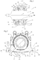
Figure 1 is a longitudinal cross section of a bearing assembly according an embodiment of the invention, cut by the plane I-I ofFig. 2 ; -
Figure 2 is a cross section of a pedestal bearing housing of the bearing assembly offigure 1 cut by the plane II-II ofFig. 1 ; -
Figure 3 is a view from below of the pedestal bearing housing ofFig. 2 ; -
Figure 4 is an isometric view of the pedestal bearing housing ofFig. 2 ; -
Figure 5 is view from below of a pedestal bearing housing according to another embodiment of the invention. - Corresponding reference numerals refer to the same or corresponding parts in each of the figures.
- With reference to
Figs. 1 to 4 , a bearingassembly 10 for guiding arotating shaft 12 in rotation about arotation axis 100 includes abearing 14 fitted onto theshaft 12 and apedestal bearing housing 16 for affixing the bearing assembly 1 to a planar surface of a base (not shown). - The bearing 14 illustrated in the drawings is a spherical roller bearing which consists of a single
outer ring 18 provided with a singlespherical raceway 20, a singleinner ring 22 provided with twospherical raceways 24, two rows of rollingbodies 26, in this case spherical rollers, and one or twocages 27 for guiding the rollingbodies 26. Theinner ring 22 has a tapered inner face and is force-fitted onto theshaft 12 by means of a slit taperedsleeve 28 and of anut 29. In the illustrated embodiment, theouter ring 18 has two end faces 30 at equal distance of a centre of rotation O of the bearing and an externalcylindrical face 32, which is press-fitted into acylindrical bearing seat 34 provided in thepedestal bearing housing 16. The axial position of theouter ring 18 can be secured by one or two spacer rings 36, each inserted between one of the end faces 30 and anend shoulder 38 of the bearingseat 34. Therevolution axis 200 defined by the cylindrical bearing seat will be a reference axis for the entire description. As is well known in the art, thespherical roller bearing 14 allows a degree of rotation of therotation axis 100 of the shaft about the centre of rotation O and the particular position illustrated inFig. 1 , with therotation axis 100 aligned with therevolution axis 200, is only one particular position. The section plane II-II ofFig. 2 is perpendicular to therevolution axis 200 and contains the centre of rotation O of the bearing. This transversal reference plane II-II is at equal distance from the two end faces 30 of theouter ring 18 and at equal distance of theshoulders 38 of the bearingseat 34. - The
pedestal bearing housing 16 is preferably made of ductile cast iron and consists of two parts, namely acap 40 and apedestal 42 fixed to one another by any convenient means, preferably by detachable fixing elements such asbolts 44. The bearingseat 34 is defined by internal surfaces of thecap 40 andpedestal 42. Thepedestal 42 has aplanar support surface 46, which lies in asupport plane 300 parallel to the revolution axis, and is intended to rest on a planar face of a base or foundation. The median longitudinal plane I-I, which contains therevolution axis 200 and is perpendicular to thesupport plane 300, is a plane of symmetry of the bearingseat 34. - The
pedestal 42 comprises twoattachment flange portions 48 protruding on opposite sides of the median longitudinal plane I-I. As shown in particular inFig. 3 , each of the twoattachment flange portions 48 includes anupper flange wall 50 protruding away from the median longitudinal plane I-I and substantially perpendicular to the median longitudinal plane I-I, an outer longitudinal supportingwall 52 and an inner longitudinal supportingwall 54 extending in a direction parallel to the median longitudinal plane I-I, and two outertransverse supporting walls 56 each extending between the outer longitudinal supportingwall 52 to the inner longitudinal supportingwall 54. The outer longitudinal supportingwall 52, inner longitudinal supportingwall 54 and outertransverse walls 56 extend from theupper flange wall 50 towards thesupport plane 300 and have edges that lie in the support plane to form parts of theplanar support surface 46 of the pedestal. Aflange cavity 58 is provided between the outer longitudinal supportingwall 52,upper flange wall 50, inner longitudinal supportingwall 54, outertransverse walls 56 andsupport plane 300. Theupper flange wall 50 is provided with two throughholes 60, which open into theflange cavity 58, each with a hole axis perpendicular to thesupport plane 300. These throughholes 60 are suitable intended for inserting bolts or other fixing elements (not shown) for securing the bearingassembly 10 to a base or foundation. - The pedestal further includes an
intermediate portion 62 between the twoflange portions 48. Theintermediate portion 62 includes two intermediate outertransverse walls 64 each parallel or substantially coplanar with one of the two outertransverse walls 56 of each of the twoflange portions 48, and four inner reinforcingwalls 66 each extending from one of the two intermediate outertransverse walls 64 to a commonmedian foot 68 to form a cross. The median foot is located at the intersection between the longitudinal median plane II-II and the transversal reference plane I-I, i.e. directly below the centre of rotation O of the bearing. Themedian foot 68 protrudes towards thesupport plane 300 and has a median support face that lies in the support plane and is part of theplanar support surface 46. The four slantedinner reinforcing walls 66 are each at an angle of between 30° and 60° to the outer intermediate transverse walls 64 (i.e. two adjacent inner reinforcingwalls 66 are at an angle of between 60° and 120° with one another). The intermediate outertransverse walls 64 and inner reinforcingwalls 66 extend from the bearingseat 34 towards thesupport plane 300 and have edges that lie in thesupport plane 300 to form part of theplanar support surface 46 of thepedestal 42.Intermediate cavities 70 are formed between the intermediate outertransverse walls 64, the innerlongitudinal wall 54 of each of the twoflange portions 48, and the inner reinforcingwalls 66. - Because of the
nut 29 received within thepedestal bearing housing 16 for fixing theinner ring 22 of thebearing 14 onto theshaft 12, thebearing 14 is slightly offset in the axial direction with respect to the bearing housing. In other words, the transversal reference plane II-II is offset with respect to the pedestal, i.e. it is closer to one of the two outertransverse walls 56 of each of the twoflange portions 48 than to the other one of the two outertransverse walls 56 of each of the twoflange portions 48. - The
pedestal bearing housing 16 further comprises twotransverse ribs 72 each extending in the transversal reference plane II-II from the bearingseat 34 to the inner longitudinal supportingwall 54 of a respective one of the twoflange portions 48. More specifically, each of the tworibs 72 extends from the inner longitudinal supportingwall 54 of the respective one of the twoflange portions 48 to themedian foot 68. Each of the twotransverse ribs 72 has a lowerfree edge 74 that lies at a distance from thesupport plane 300. As shown inFig. 2 , the lowerfree edge 74 of each of the two transverse ribs has a curved cross-section in the transversal reference plane II-II with a convex intermediate portion 74.1 between to concave end 74.2, 74.3 portions, which reach thesupport plane 300 preferably at an angle of more than 45°. The maximal distance D1 between thesupport plane 300 and thefree edge 74 is found in the concave portion 74.2. The minimal distance D2 between the convex intermediate portion 74.1 and thesupport plane 300 is found in a transition zone between the convex intermediate portion 74.1 and the concave end portion 74.3. Depending on the size of the pedestal bearing housing, the ration D1/D2 is between 3 and 7. The twotransverse ribs 72 are effective to transfer load from the bearingseat 34 to the innerlongitudinal walls 54, without substantially increasing the stress in the region of theupper flange wall 50 and of the through holes 60. Hence, the stress, which would be too high in the region of theupper flange wall 50 without thetransverse ribs 72, lies within limits that ensure an indefinite operating life to the pedestal housing. Eachtransverse rib 72 spans an angle A1, measured in the transversal reference plane II-II from the median longitudinal plane I-I to the inner longitudinal supportingwall 54, of preferably more than 35° and less than 55°, in the present case of approximately 43°. Themedian foot 68 on the other hand spans and angle A2, measured in the transversal reference plane II-II from the median longitudinal plane I-I to the inner longitudinal beginning of thetransverse rib 72, of preferably more than 3° but less than 10°, in the illustrated embodiment about 3,5°. The median longitudinal plane I-I is a plane of symmetry for theplanar support surface 46 of thepedestal 42 and for thetransverse ribs 72, and preferably for the outer longitudinal supportingwalls 52, inner longitudinal supportingwalls 54,upper flange walls 50 and preferably for the outertransverse walls 56, intermediate outertransverse walls 64 and inner reinforcingwalls 66. - In the variant of
Fig. 5 , the slanted inner reinforcing walls are omitted and the archedtransverse ribs 72 extend from the bearingseat 34 to the inner longitudinal supportingwall 54 of the respective one of the twoflange portions 48 and to themedian foot 68, which protrudes towards thesupport plane 300 and has a median support surface that lies in the support plane and is part of theplanar support surface 46. - Experimental results show that the ribs have a significant influence on the rigidity and deformation in particular when radial load is applied in a direction globally in the transverse reference plane II, but significantly offset with respect to a 0° direction defined as the radial direction towards the
median foot 68, e.g. in a radial direction towards one of the inner longitudinal supportingwalls 54. - A number of other variants are contemplated within the scope of the claims. In particular, the transverse reference plane II-II can be at mid-distance of the two outer
transverse walls 56 of eachflange portions 48. The intermediate outertransverse walls 64 can be dispensed with, or can have a free edge that remains at a distance from thesupport plane 300, in which case they operate like bridges between the twoflange portions 48 without transmitting load to the base to which the pedestal is fixed. The bearinghousing 16 can be made in one piece, or in more than two parts, in any suitable material, including e.g. grey cast iron, ductile cast iron, or cast aluminium. - The bearing 14 can be of any type, including spherical and non-spherical bearings, plain bearings and rolling bearings with rolling
bodies 26 of any kind, including tapered, cylindrical, barrel or spherical rollers, balls and needles or combinations thereof, with one or more rows of rolling bodies, one or more outer rings and one or more inner rings. The inner ring can be force-fitted or otherwise fixed onto the shaft by any means. The outer ring can be omitted, in which case the bearingseat 34 is a bearing raceway or, if the bearing is a slide bearing, a slide bearing surface. Similarly, the inner ring can be omitted, and the inner raceway (in the case of a roller bearing) or inner slide bearing surface (in the case of a plain bearing) can be formed directly on the shaft. The bearingseat 34 can have a cylindrical shape, a stepped cylindrical shape, a conical shape, with or without splines.
Claims (15)
- A pedestal bearing housing (16) comprising a bearing seat (34), two attachment flange portions (48) extending between the bearing seat (34) and a support plane (300), the two attachment flange portions (48) protruding on opposite sides of a median longitudinal plane (I-I) perpendicular to the support plane (300), each of the two attachment flange portions (48) including an upper flange wall (50) protruding away from the median longitudinal plane (I-I), an outer longitudinal supporting wall (52) and an inner longitudinal supporting wall (54) extending in a direction parallel to the median longitudinal plane (I-I), and two outer transverse supporting walls (56) each extending from the outer longitudinal supporting wall (52) to the inner longitudinal supporting wall (54), the outer longitudinal supporting wall (52), inner longitudinal supporting wall (54) and outer transverse walls (56) extending from the upper flange wall (50) towards the support plane (300) and having edges that lie in the support plane (300) to form at least part of a planar support surface (46) of the pedestal bearing housing (16), a flange cavity (58) being provided between the upper flange wall (50), outer longitudinal supporting wall (52), inner longitudinal supporting wall (54), outer transverse walls (56) and support plane (300), the upper flange wall (50) being provided with at least one through hole (60) which opens into the flange cavity (58), characterised in that the pedestal bearing housing (16) further comprises two transverse ribs (72) each extending at least from the bearing seat (34) to the inner longitudinal supporting wall (54) of a respective one of the two flange portions (48), in a common transversal reference plane (II-II) perpendicular to the median longitudinal plane (I-I) and to the support plane (300) and located between the two outer transverse supporting walls (56) of each of the two flange portions (48).
- The pedestal bearing housing (16) of claim 1, characterised in that each of the two transverse ribs (72) has a lower free edge (74) that lies at a distance from the support plane (300).
- The pedestal bearing housing of claim 2, characterised in that the lower free edge (74) of each of the two transverse ribs (72) has a curved cross section in the transversal reference plane (II-II).
- The pedestal bearing housing (16) of claim 3, further comprising an intermediate portion (62) extending between the bearing seat (34) and the support plane (300) and between the two flange portions (48), wherein the intermediate portion (62) includes at least a median foot (68) protruding from the bearing seat (34) towards the support plane (300), the median foot (68) having a median support surface that lies in the support plane (300) and is part of the planar support surface (46), and wherein each of the two transverse ribs (72) extends from the inner longitudinal supporting wall (54) of the respective one of the two flange portions (48) to the median foot (68).
- The pedestal bearing housing of claim 4, characterised in that the lower free edge (74) of each of the two transverse ribs (72) has a convex intermediate portion, a concave end portion between the convex intermediate portion and the median foot (48) and a concave end portion between the convex intermediate portion and the inner longitudinal supporting wall (54) of the respective one of the two flange portions (48).
- The pedestal bearing housing (16) of any one of claims 4 to 5, characterised in that the intermediate portion (62) further includes two intermediate outer transverse walls (64) each extending from one of the two flange portions (48) to the other of the two flange portions (48), wherein the median foot (68) lies between the two intermediate outer transverse walls (64) and wherein one or more intermediate cavities (70) are provided between the intermediate outer transverse walls (64) and the inner longitudinal wall (54) of each of the two flange portions (48), and, preferably, the two intermediate outer transverse walls (64) extend from the bearing seat (34) towards the support plane (300) and have edges that lie in the support plane (300) to form part of the planar support surface (46).
- The pedestal bearing housing (16) of claim 6, characterised in that the intermediate portion (62) further includes at least two inner reinforcing walls (66) each extending from one of the two intermediate outer transverse walls (64) to the median foot (68).
- The pedestal bearing housing (16) of claim 7, characterised in that the at least two inner reinforcing walls (66) extend from the bearing seat (34) towards the support plane (300) and have edges that lie in the support plane (300) to form part of the planar support surface (46).
- The pedestal bearing housing (16) of claim 7 or claim 8, characterised in that the at least two inner reinforcing walls (66) include at least two slanted inner reinforcing walls (66) each at an angle of between 30° and 60° to the outer intermediate transverse walls (64), and preferably at least four slanted inner reinforcing walls (66) each at an angle of between 30° and 60° to the outer intermediate transverse walls (64) and forming a cross.
- The pedestal bearing housing (16) of any one of the preceding claims, characterised in that the bearing seat (34) has two axial ends (38), located on each side and at equal distance of the transversal reference plane (II-II).
- The pedestal bearing housing (16) of any one of the preceding claims, characterised in that the transversal reference plane (II-II) is not at equal distance of the two outer transverse walls (56) of each of the two flange portions (48).
- The pedestal bearing housing (16) of any one of the preceding claims, characterised in that the pedestal bearing housing (16) comprises a cap (40) and a pedestal (42), which comprises the pedestal flange portions (48), the cap (40) and pedestal (42) being fixed to one another, preferably by removable fastening elements (44), the bearing seat (34) formed by walls of the cap (40) and pedestal (42).
- A bearing assembly (10) comprising the pedestal bearing housing (16) of any one of the preceding claims and at least one outer bearing ring (18) fitted into the bearing seat (34).
- The bearing assembly (10) of claim 13, characterised in that the outer bearing ring (18) has a spherical race (20) having a centre (O) located in the transversal reference plane (II-II).
- The bearing assembly (10) of claim 13 or claim 14, characterised in that the outer bearing ring (18) has two end walls (30) at equal distance from the transversal reference plane (II-II).
Applications Claiming Priority (1)
| Application Number | Priority Date | Filing Date | Title |
|---|---|---|---|
| PCT/EP2015/057891 WO2016162093A1 (en) | 2015-04-10 | 2015-04-10 | Pedestal bearing housing and associated bearing assembly |
Publications (3)
| Publication Number | Publication Date |
|---|---|
| EP3280924A1 EP3280924A1 (en) | 2018-02-14 |
| EP3280924B1 true EP3280924B1 (en) | 2019-02-13 |
| EP3280924B8 EP3280924B8 (en) | 2019-04-24 |
Family
ID=52815004
Family Applications (1)
| Application Number | Title | Priority Date | Filing Date |
|---|---|---|---|
| EP15714841.2A Active EP3280924B8 (en) | 2015-04-10 | 2015-04-10 | Pedestal bearing housing and associated bearing assembly |
Country Status (2)
| Country | Link |
|---|---|
| EP (1) | EP3280924B8 (en) |
| WO (1) | WO2016162093A1 (en) |
Families Citing this family (1)
| Publication number | Priority date | Publication date | Assignee | Title |
|---|---|---|---|---|
| JP2022127909A (en) * | 2021-02-22 | 2022-09-01 | Ntn株式会社 | plummer block |
Family Cites Families (5)
| Publication number | Priority date | Publication date | Assignee | Title |
|---|---|---|---|---|
| US5655845A (en) * | 1995-09-27 | 1997-08-12 | Skf Usa Inc. | Bearing housing seal |
| FR2878301A1 (en) * | 2004-11-24 | 2006-05-26 | Snr Roulements Sa | BEARING BEARING COMPRISING RIGIDIFICATION MEANS |
| CN102695889B (en) * | 2009-11-27 | 2017-10-03 | Skf公司 | For the bear box of rolling bearing and for the roll line for the continuously casting machine for combining the antifriction-bearing case |
| CN202012574U (en) * | 2011-03-17 | 2011-10-19 | 远立行工业股份有限公司 | Heat dissipation type bearing pedestal body |
| WO2013085448A1 (en) | 2011-12-09 | 2013-06-13 | Aktiebolaget Skf | Bearing housing |
-
2015
- 2015-04-10 EP EP15714841.2A patent/EP3280924B8/en active Active
- 2015-04-10 WO PCT/EP2015/057891 patent/WO2016162093A1/en not_active Ceased
Non-Patent Citations (1)
| Title |
|---|
| None * |
Also Published As
| Publication number | Publication date |
|---|---|
| WO2016162093A1 (en) | 2016-10-13 |
| EP3280924B8 (en) | 2019-04-24 |
| EP3280924A1 (en) | 2018-02-14 |
Similar Documents
| Publication | Publication Date | Title |
|---|---|---|
| US20100166355A1 (en) | Metal cage for roller bearing | |
| US8052331B2 (en) | Bearing fixing device and bearing unit | |
| GB2323823A (en) | Hub unit for supporting a vehicle wheel | |
| CN103228936B (en) | Annular bearing | |
| US12038044B2 (en) | Rolling bearing | |
| US10598218B2 (en) | Angular contact roller bearing and method and device for the assembly thereof | |
| US10690181B2 (en) | Angular contact roller bearing and method and device for the assembly thereof | |
| CN103797258A (en) | Tapered roller bearing and its installation structure | |
| CN102177355A (en) | Device for rotatably coupling two coaxial connection elements | |
| US8911155B2 (en) | Cage for thrust roller bearing | |
| US20150267754A1 (en) | Bearing device | |
| US9273728B2 (en) | Rolling bearing having rings with stepped surfaces opposite to the raceways | |
| EP2825782B1 (en) | Wheel bearing arrangement | |
| US20220332144A1 (en) | Caster | |
| WO2016162093A1 (en) | Pedestal bearing housing and associated bearing assembly | |
| EP2703665B1 (en) | Outer double-row ball bearing assembly combined with inner plain bearing | |
| JP2000130444A (en) | Double row rolling bearing unit | |
| JP2012149703A (en) | Spherical roller bearing | |
| US12292082B2 (en) | Bearing ring with sealing disc | |
| US20020001425A1 (en) | Thrust ring and method for producing a thrust ring, bearing system for bolts of universal joints and cardan joint arrangement | |
| JP2010002043A (en) | Bearing for cross shaft coupling | |
| CN111749983B (en) | Bearing and bearing system of wind generating set | |
| JP3911961B2 (en) | Roller bearing | |
| CN104074873B (en) | For at least having the spacer of the rolling bearing of buttress brace | |
| US9127717B1 (en) | Spacer for rolling bearing having at least a reinforcing beam |
Legal Events
| Date | Code | Title | Description |
|---|---|---|---|
| STAA | Information on the status of an ep patent application or granted ep patent |
Free format text: STATUS: THE INTERNATIONAL PUBLICATION HAS BEEN MADE |
|
| PUAI | Public reference made under article 153(3) epc to a published international application that has entered the european phase |
Free format text: ORIGINAL CODE: 0009012 |
|
| STAA | Information on the status of an ep patent application or granted ep patent |
Free format text: STATUS: REQUEST FOR EXAMINATION WAS MADE |
|
| 17P | Request for examination filed |
Effective date: 20171003 |
|
| AK | Designated contracting states |
Kind code of ref document: A1 Designated state(s): AL AT BE BG CH CY CZ DE DK EE ES FI FR GB GR HR HU IE IS IT LI LT LU LV MC MK MT NL NO PL PT RO RS SE SI SK SM TR |
|
| AX | Request for extension of the european patent |
Extension state: BA ME |
|
| DAV | Request for validation of the european patent (deleted) | ||
| DAX | Request for extension of the european patent (deleted) | ||
| GRAP | Despatch of communication of intention to grant a patent |
Free format text: ORIGINAL CODE: EPIDOSNIGR1 |
|
| STAA | Information on the status of an ep patent application or granted ep patent |
Free format text: STATUS: GRANT OF PATENT IS INTENDED |
|
| INTG | Intention to grant announced |
Effective date: 20180815 |
|
| GRAS | Grant fee paid |
Free format text: ORIGINAL CODE: EPIDOSNIGR3 |
|
| GRAJ | Information related to disapproval of communication of intention to grant by the applicant or resumption of examination proceedings by the epo deleted |
Free format text: ORIGINAL CODE: EPIDOSDIGR1 |
|
| GRAL | Information related to payment of fee for publishing/printing deleted |
Free format text: ORIGINAL CODE: EPIDOSDIGR3 |
|
| STAA | Information on the status of an ep patent application or granted ep patent |
Free format text: STATUS: REQUEST FOR EXAMINATION WAS MADE |
|
| GRAR | Information related to intention to grant a patent recorded |
Free format text: ORIGINAL CODE: EPIDOSNIGR71 |
|
| STAA | Information on the status of an ep patent application or granted ep patent |
Free format text: STATUS: GRANT OF PATENT IS INTENDED |
|
| GRAA | (expected) grant |
Free format text: ORIGINAL CODE: 0009210 |
|
| STAA | Information on the status of an ep patent application or granted ep patent |
Free format text: STATUS: THE PATENT HAS BEEN GRANTED |
|
| INTC | Intention to grant announced (deleted) | ||
| INTG | Intention to grant announced |
Effective date: 20181221 |
|
| AK | Designated contracting states |
Kind code of ref document: B1 Designated state(s): AL AT BE BG CH CY CZ DE DK EE ES FI FR GB GR HR HU IE IS IT LI LT LU LV MC MK MT NL NO PL PT RO RS SE SI SK SM TR |
|
| REG | Reference to a national code |
Ref country code: GB Ref legal event code: FG4D |
|
| REG | Reference to a national code |
Ref country code: CH Ref legal event code: EP Ref country code: AT Ref legal event code: REF Ref document number: 1096389 Country of ref document: AT Kind code of ref document: T Effective date: 20190215 |
|
| GRAT | Correction requested after decision to grant or after decision to maintain patent in amended form |
Free format text: ORIGINAL CODE: EPIDOSNCDEC |
|
| REG | Reference to a national code |
Ref country code: IE Ref legal event code: FG4D |
|
| REG | Reference to a national code |
Ref country code: DE Ref legal event code: R096 Ref document number: 602015024578 Country of ref document: DE |
|
| REG | Reference to a national code |
Ref country code: CH Ref legal event code: PK Free format text: BERICHTIGUNG B8 |
|
| RAP2 | Party data changed (patent owner data changed or rights of a patent transferred) |
Owner name: SNR WAELZLAGER GMBH |
|
| REG | Reference to a national code |
Ref country code: DE Ref legal event code: R082 Ref document number: 602015024578 Country of ref document: DE Representative=s name: BROYDE, MARC, FR |
|
| REG | Reference to a national code |
Ref country code: LT Ref legal event code: MG4D |
|
| REG | Reference to a national code |
Ref country code: NL Ref legal event code: MP Effective date: 20190213 |
|
| PG25 | Lapsed in a contracting state [announced via postgrant information from national office to epo] |
Ref country code: LT Free format text: LAPSE BECAUSE OF FAILURE TO SUBMIT A TRANSLATION OF THE DESCRIPTION OR TO PAY THE FEE WITHIN THE PRESCRIBED TIME-LIMIT Effective date: 20190213 Ref country code: FI Free format text: LAPSE BECAUSE OF FAILURE TO SUBMIT A TRANSLATION OF THE DESCRIPTION OR TO PAY THE FEE WITHIN THE PRESCRIBED TIME-LIMIT Effective date: 20190213 Ref country code: PT Free format text: LAPSE BECAUSE OF FAILURE TO SUBMIT A TRANSLATION OF THE DESCRIPTION OR TO PAY THE FEE WITHIN THE PRESCRIBED TIME-LIMIT Effective date: 20190613 Ref country code: NO Free format text: LAPSE BECAUSE OF FAILURE TO SUBMIT A TRANSLATION OF THE DESCRIPTION OR TO PAY THE FEE WITHIN THE PRESCRIBED TIME-LIMIT Effective date: 20190513 Ref country code: SE Free format text: LAPSE BECAUSE OF FAILURE TO SUBMIT A TRANSLATION OF THE DESCRIPTION OR TO PAY THE FEE WITHIN THE PRESCRIBED TIME-LIMIT Effective date: 20190213 Ref country code: NL Free format text: LAPSE BECAUSE OF FAILURE TO SUBMIT A TRANSLATION OF THE DESCRIPTION OR TO PAY THE FEE WITHIN THE PRESCRIBED TIME-LIMIT Effective date: 20190213 |
|
| PG25 | Lapsed in a contracting state [announced via postgrant information from national office to epo] |
Ref country code: GR Free format text: LAPSE BECAUSE OF FAILURE TO SUBMIT A TRANSLATION OF THE DESCRIPTION OR TO PAY THE FEE WITHIN THE PRESCRIBED TIME-LIMIT Effective date: 20190514 Ref country code: HR Free format text: LAPSE BECAUSE OF FAILURE TO SUBMIT A TRANSLATION OF THE DESCRIPTION OR TO PAY THE FEE WITHIN THE PRESCRIBED TIME-LIMIT Effective date: 20190213 Ref country code: LV Free format text: LAPSE BECAUSE OF FAILURE TO SUBMIT A TRANSLATION OF THE DESCRIPTION OR TO PAY THE FEE WITHIN THE PRESCRIBED TIME-LIMIT Effective date: 20190213 Ref country code: BG Free format text: LAPSE BECAUSE OF FAILURE TO SUBMIT A TRANSLATION OF THE DESCRIPTION OR TO PAY THE FEE WITHIN THE PRESCRIBED TIME-LIMIT Effective date: 20190513 Ref country code: IS Free format text: LAPSE BECAUSE OF FAILURE TO SUBMIT A TRANSLATION OF THE DESCRIPTION OR TO PAY THE FEE WITHIN THE PRESCRIBED TIME-LIMIT Effective date: 20190613 Ref country code: RS Free format text: LAPSE BECAUSE OF FAILURE TO SUBMIT A TRANSLATION OF THE DESCRIPTION OR TO PAY THE FEE WITHIN THE PRESCRIBED TIME-LIMIT Effective date: 20190213 |
|
| REG | Reference to a national code |
Ref country code: AT Ref legal event code: MK05 Ref document number: 1096389 Country of ref document: AT Kind code of ref document: T Effective date: 20190213 |
|
| PG25 | Lapsed in a contracting state [announced via postgrant information from national office to epo] |
Ref country code: ES Free format text: LAPSE BECAUSE OF FAILURE TO SUBMIT A TRANSLATION OF THE DESCRIPTION OR TO PAY THE FEE WITHIN THE PRESCRIBED TIME-LIMIT Effective date: 20190213 Ref country code: AL Free format text: LAPSE BECAUSE OF FAILURE TO SUBMIT A TRANSLATION OF THE DESCRIPTION OR TO PAY THE FEE WITHIN THE PRESCRIBED TIME-LIMIT Effective date: 20190213 Ref country code: CZ Free format text: LAPSE BECAUSE OF FAILURE TO SUBMIT A TRANSLATION OF THE DESCRIPTION OR TO PAY THE FEE WITHIN THE PRESCRIBED TIME-LIMIT Effective date: 20190213 Ref country code: DK Free format text: LAPSE BECAUSE OF FAILURE TO SUBMIT A TRANSLATION OF THE DESCRIPTION OR TO PAY THE FEE WITHIN THE PRESCRIBED TIME-LIMIT Effective date: 20190213 Ref country code: EE Free format text: LAPSE BECAUSE OF FAILURE TO SUBMIT A TRANSLATION OF THE DESCRIPTION OR TO PAY THE FEE WITHIN THE PRESCRIBED TIME-LIMIT Effective date: 20190213 Ref country code: SK Free format text: LAPSE BECAUSE OF FAILURE TO SUBMIT A TRANSLATION OF THE DESCRIPTION OR TO PAY THE FEE WITHIN THE PRESCRIBED TIME-LIMIT Effective date: 20190213 Ref country code: RO Free format text: LAPSE BECAUSE OF FAILURE TO SUBMIT A TRANSLATION OF THE DESCRIPTION OR TO PAY THE FEE WITHIN THE PRESCRIBED TIME-LIMIT Effective date: 20190213 |
|
| REG | Reference to a national code |
Ref country code: DE Ref legal event code: R097 Ref document number: 602015024578 Country of ref document: DE |
|
| PG25 | Lapsed in a contracting state [announced via postgrant information from national office to epo] |
Ref country code: PL Free format text: LAPSE BECAUSE OF FAILURE TO SUBMIT A TRANSLATION OF THE DESCRIPTION OR TO PAY THE FEE WITHIN THE PRESCRIBED TIME-LIMIT Effective date: 20190213 Ref country code: SM Free format text: LAPSE BECAUSE OF FAILURE TO SUBMIT A TRANSLATION OF THE DESCRIPTION OR TO PAY THE FEE WITHIN THE PRESCRIBED TIME-LIMIT Effective date: 20190213 |
|
| REG | Reference to a national code |
Ref country code: CH Ref legal event code: PL |
|
| REG | Reference to a national code |
Ref country code: BE Ref legal event code: MM Effective date: 20190430 |
|
| PLBE | No opposition filed within time limit |
Free format text: ORIGINAL CODE: 0009261 |
|
| STAA | Information on the status of an ep patent application or granted ep patent |
Free format text: STATUS: NO OPPOSITION FILED WITHIN TIME LIMIT |
|
| PG25 | Lapsed in a contracting state [announced via postgrant information from national office to epo] |
Ref country code: AT Free format text: LAPSE BECAUSE OF FAILURE TO SUBMIT A TRANSLATION OF THE DESCRIPTION OR TO PAY THE FEE WITHIN THE PRESCRIBED TIME-LIMIT Effective date: 20190213 Ref country code: MC Free format text: LAPSE BECAUSE OF FAILURE TO SUBMIT A TRANSLATION OF THE DESCRIPTION OR TO PAY THE FEE WITHIN THE PRESCRIBED TIME-LIMIT Effective date: 20190213 Ref country code: LU Free format text: LAPSE BECAUSE OF NON-PAYMENT OF DUE FEES Effective date: 20190410 |
|
| 26N | No opposition filed |
Effective date: 20191114 |
|
| GBPC | Gb: european patent ceased through non-payment of renewal fee |
Effective date: 20190513 |
|
| PG25 | Lapsed in a contracting state [announced via postgrant information from national office to epo] |
Ref country code: CH Free format text: LAPSE BECAUSE OF NON-PAYMENT OF DUE FEES Effective date: 20190430 Ref country code: LI Free format text: LAPSE BECAUSE OF NON-PAYMENT OF DUE FEES Effective date: 20190430 |
|
| PG25 | Lapsed in a contracting state [announced via postgrant information from national office to epo] |
Ref country code: BE Free format text: LAPSE BECAUSE OF NON-PAYMENT OF DUE FEES Effective date: 20190430 Ref country code: SI Free format text: LAPSE BECAUSE OF FAILURE TO SUBMIT A TRANSLATION OF THE DESCRIPTION OR TO PAY THE FEE WITHIN THE PRESCRIBED TIME-LIMIT Effective date: 20190213 |
|
| PG25 | Lapsed in a contracting state [announced via postgrant information from national office to epo] |
Ref country code: TR Free format text: LAPSE BECAUSE OF FAILURE TO SUBMIT A TRANSLATION OF THE DESCRIPTION OR TO PAY THE FEE WITHIN THE PRESCRIBED TIME-LIMIT Effective date: 20190213 |
|
| PG25 | Lapsed in a contracting state [announced via postgrant information from national office to epo] |
Ref country code: IE Free format text: LAPSE BECAUSE OF NON-PAYMENT OF DUE FEES Effective date: 20190410 Ref country code: GB Free format text: LAPSE BECAUSE OF NON-PAYMENT OF DUE FEES Effective date: 20190513 |
|
| PG25 | Lapsed in a contracting state [announced via postgrant information from national office to epo] |
Ref country code: CY Free format text: LAPSE BECAUSE OF FAILURE TO SUBMIT A TRANSLATION OF THE DESCRIPTION OR TO PAY THE FEE WITHIN THE PRESCRIBED TIME-LIMIT Effective date: 20190213 |
|
| PG25 | Lapsed in a contracting state [announced via postgrant information from national office to epo] |
Ref country code: MT Free format text: LAPSE BECAUSE OF FAILURE TO SUBMIT A TRANSLATION OF THE DESCRIPTION OR TO PAY THE FEE WITHIN THE PRESCRIBED TIME-LIMIT Effective date: 20190213 Ref country code: HU Free format text: LAPSE BECAUSE OF FAILURE TO SUBMIT A TRANSLATION OF THE DESCRIPTION OR TO PAY THE FEE WITHIN THE PRESCRIBED TIME-LIMIT; INVALID AB INITIO Effective date: 20150410 |
|
| PG25 | Lapsed in a contracting state [announced via postgrant information from national office to epo] |
Ref country code: MK Free format text: LAPSE BECAUSE OF FAILURE TO SUBMIT A TRANSLATION OF THE DESCRIPTION OR TO PAY THE FEE WITHIN THE PRESCRIBED TIME-LIMIT Effective date: 20190213 |
|
| PGFP | Annual fee paid to national office [announced via postgrant information from national office to epo] |
Ref country code: IT Payment date: 20250424 Year of fee payment: 11 |
|
| PGFP | Annual fee paid to national office [announced via postgrant information from national office to epo] |
Ref country code: DE Payment date: 20260422 Year of fee payment: 12 |
|
| PGFP | Annual fee paid to national office [announced via postgrant information from national office to epo] |
Ref country code: FR Payment date: 20260420 Year of fee payment: 12 |