EP3280507B1 - Cooling of pump heads in carbon dioxide chromatography systems - Google Patents
Cooling of pump heads in carbon dioxide chromatography systems Download PDFInfo
- Publication number
- EP3280507B1 EP3280507B1 EP16777256.5A EP16777256A EP3280507B1 EP 3280507 B1 EP3280507 B1 EP 3280507B1 EP 16777256 A EP16777256 A EP 16777256A EP 3280507 B1 EP3280507 B1 EP 3280507B1
- Authority
- EP
- European Patent Office
- Prior art keywords
- coolant
- pump head
- passageway
- fluid
- stream
- Prior art date
- Legal status (The legal status is an assumption and is not a legal conclusion. Google has not performed a legal analysis and makes no representation as to the accuracy of the status listed.)
- Active
Links
Images




Classifications
-
- F—MECHANICAL ENGINEERING; LIGHTING; HEATING; WEAPONS; BLASTING
- F25—REFRIGERATION OR COOLING; COMBINED HEATING AND REFRIGERATION SYSTEMS; HEAT PUMP SYSTEMS; MANUFACTURE OR STORAGE OF ICE; LIQUEFACTION SOLIDIFICATION OF GASES
- F25B—REFRIGERATION MACHINES, PLANTS OR SYSTEMS; COMBINED HEATING AND REFRIGERATION SYSTEMS; HEAT PUMP SYSTEMS
- F25B25/00—Machines, plants or systems, using a combination of modes of operation covered by two or more of the groups F25B1/00 - F25B23/00
- F25B25/005—Machines, plants or systems, using a combination of modes of operation covered by two or more of the groups F25B1/00 - F25B23/00 using primary and secondary systems
-
- B—PERFORMING OPERATIONS; TRANSPORTING
- B01—PHYSICAL OR CHEMICAL PROCESSES OR APPARATUS IN GENERAL
- B01D—SEPARATION
- B01D15/00—Separating processes involving the treatment of liquids with solid sorbents; Apparatus therefor
- B01D15/08—Selective adsorption, e.g. chromatography
- B01D15/10—Selective adsorption, e.g. chromatography characterised by constructional or operational features
- B01D15/18—Selective adsorption, e.g. chromatography characterised by constructional or operational features relating to flow patterns
-
- B—PERFORMING OPERATIONS; TRANSPORTING
- B01—PHYSICAL OR CHEMICAL PROCESSES OR APPARATUS IN GENERAL
- B01D—SEPARATION
- B01D15/00—Separating processes involving the treatment of liquids with solid sorbents; Apparatus therefor
- B01D15/08—Selective adsorption, e.g. chromatography
- B01D15/26—Selective adsorption, e.g. chromatography characterised by the separation mechanism
- B01D15/40—Selective adsorption, e.g. chromatography characterised by the separation mechanism using supercritical fluid as mobile phase or eluent
-
- G—PHYSICS
- G01—MEASURING; TESTING
- G01N—INVESTIGATING OR ANALYSING MATERIALS BY DETERMINING THEIR CHEMICAL OR PHYSICAL PROPERTIES
- G01N30/00—Investigating or analysing materials by separation into components using adsorption, absorption or similar phenomena or using ion-exchange, e.g. chromatography or field flow fractionation
- G01N30/02—Column chromatography
- G01N30/26—Conditioning of the fluid carrier; Flow patterns
- G01N30/28—Control of physical parameters of the fluid carrier
- G01N30/30—Control of physical parameters of the fluid carrier of temperature
-
- F—MECHANICAL ENGINEERING; LIGHTING; HEATING; WEAPONS; BLASTING
- F04—POSITIVE - DISPLACEMENT MACHINES FOR LIQUIDS; PUMPS FOR LIQUIDS OR ELASTIC FLUIDS
- F04B—POSITIVE-DISPLACEMENT MACHINES FOR LIQUIDS; PUMPS
- F04B2205/00—Fluid parameters
- F04B2205/09—Flow through the pump
Definitions
- the present disclosure relates to techniques for cooling of pump heads in carbon dioxide chromatography systems.
- the present disclosure also relates to methodologies, systems and apparatus for providing a substantially equal heat transfer from each of at least two pump heads.
- multiple pumps may be arranged in a parallel or serial fashion to pump fluids in a fluid chromatography system.
- Chromatography involves the flowing of a mobile phase over a stationary phase to effect separation.
- pressurized mobile phases were introduced.
- Carbon dioxide based chromatographic systems use CO 2 as a component of the mobile phase flow stream, and the CO 2 based mobile phase is delivered from the pumps and carried through the separation column as a pressurized liquid.
- CO 2 as a mobile phase component
- one challenge is pumping the CO 2 , as small changes in temperature and/or pressure greatly change the density of CO 2 . Any fluctuation in the density of the CO 2 elevates compressibility issues, frustrating typical compressibility compensation schemes. Therefore, a need exists for chromatography systems that provide increased stability and control of temperature and pressure levels.
- the present invention is disclosed in the claims and relates to embodiments directed to pump head cooling systems for providing balanced cooling and heat transfer between multiple pump heads. Further, the embodiments are related to methodologies, systems and apparatus for pump head cooling systems that employ recursive or parallel coolant flow patterns to achieve a substantially equal average heat transfer between the pump heads and the coolant fluid. In particular, some embodiments are related to fluid cooling systems for cooling pump heads that are used in a CO 2 -based chromatography systems, i.e., a chromatography system in which the mobile phase includes CO 2 .
- the present technology relates to a pump head cooling system.
- the system includes a first pump head defining a first coolant passageway and a second coolant passageway, each passageway having an inlet into the first pump head and an outlet out of the first pump head.
- the system also includes a second pump head defining a third coolant passageway and a fourth coolant passageway, each passageway having an inlet into the second pump head and an outlet out of the second pump head.
- the outlet of the first coolant passageway is fluidly coupled to the inlet of the third coolant passageway
- the outlet of the third coolant passageway is fluidly coupled to the inlet of the fourth coolant passageway
- the outlet of the fourth coolant passageway is fluidly coupled to the inlet of the second coolant passageway.
- Embodiments of this aspect of the technology can include one or more of the following features.
- the first pump head and the second pump head are composed of, or composed in part of, stainless steel.
- the first pump head and the second pump head are adapted to operate at flow rates between 0.50 - 150.00 mL/min.
- the first pump head and the second pump head are adapted to operate at pressures up to 50 MPa.
- the system also includes a coolant pump adapted to pump a coolant fluid through the first coolant passageway, the second coolant passageway, the third coolant passageway, and the fourth coolant passageway.
- the system also includes a fluid chiller adapted to chill a coolant fluid prior to pumping the coolant fluid through the first coolant passageway.
- the system also includes: a first coolant tube adapted to fluidly couple the outlet of the first coolant passageway to the inlet of the third coolant passageway, a second coolant tube adapted to fluidly couple the outlet of the third coolant passageway to the inlet of the fourth coolant passageway, and a third coolant tube adapted to fluidly couple the outlet of the fourth coolant passageway to the inlet of the second coolant passageway.
- the present technology relates to a pump head cooling system.
- the system includes a first pump head defining a first coolant passageway and a second coolant passageway, each passageway having an inlet into the first pump head and an outlet out of the first pump head, and wherein the outlet of the first coolant passageway is fluidly coupled to the inlet of the second coolant passageway.
- the system also includes a second pump head defining a third coolant passageway and a fourth coolant passageway, each passageway having an inlet into the second pump head and an outlet out of the second pump head, and wherein the outlet of the third coolant passageway is fluidly coupled to the inlet of the fourth coolant passageway.
- the system also includes at least one coolant pump adapted to pump a first stream of coolant fluid through the first pump head and pump a second stream of coolant fluid through the second pump head, such that an average heat transfer between the first pump head and the first stream of coolant fluid is substantially equal to an average heat transfer between the second pump head and the second stream of coolant fluid.
- the system also includes a first fluid connector having one inlet and two outlets, wherein a first outlet is fluidly coupled to an entrance of the first coolant passageway and a second outlet is fluidly coupled to an entrance of the third coolant passageway.
- the system also includes a fluid connector having two inlets and a single outlet, wherein a first inlet is fluidly coupled to an outlet of the second coolant passageway and a second inlet is fluidly coupled to an outlet of the fourth coolant passageway.
- the system also includes a fluid chiller adapted to chill the first stream of coolant fluid and the second stream of coolant fluid after exiting the coolant pump.
- the system also includes a control system adapted to measure a temperature of the first pump head and a temperature of the second pump head and apply cooling to the pump head cooling system to maintain a temperature difference between the first pump head and the second pump head below 1.0 degree Celsius.
- the present technology relates to a method of cooling pump heads.
- the method includes flowing at least one stream of coolant fluid through a plurality of coolant passageways within a first pump head and a second pump head along a coolant fluid path.
- the method also includes providing an average heat transfer between the first pump head and the coolant fluid that is substantially equal to an average heat transfer between the second pump head and the coolant fluid.
- the method also includes maintaining a temperature difference between the first pump head and the second pump head below 1.0 degree Celsius. In some embodiments, the method also includes maintaining the temperature difference between the first pump head and the second pump head below 0.5 degrees Celsius. In some embodiments, maintaining the temperature difference between the first pump head and the second pump head below 0.4 degrees Celsius. In some embodiments, the method also includes chilling the at least one stream of coolant fluid prior to flowing through the plurality of coolant passageways.
- flowing at least one stream of coolant fluid includes: flowing a first coolant stream through a first coolant passageway within the first pump head, flowing the first coolant stream from an outlet of the first coolant passageway through a second coolant passageway within the second pump head, flowing the first coolant stream from an outlet of the second coolant passageway through a third coolant passageway within the second pump head, and flowing the first coolant fluid from an outlet of the third coolant passageway through a fourth coolant passageway within the first pump head.
- flowing at least one stream through a plurality of coolant passageways includes: flowing a first stream of coolant fluid from a coolant fluid source through a first coolant passageway within a first pump head, wherein the first coolant passageway has an inlet into the first pump head and an outlet out of the first pump head, flowing the first stream of coolant fluid from the outlet of the first coolant passageway to an inlet of a second coolant passageway within the first pump head, wherein the second coolant passageway has an inlet into the first pump head and an outlet out of the first pump head, flowing a second stream of coolant fluid from the coolant fluid source through a third coolant passageway within a second pump head, wherein the third coolant passageway has an inlet into the second pump head and an outlet out of the second pump head, and flowing the second stream of coolant fluid from the outlet of the third coolant passageway to an inlet of a fourth coolant passageway within the second pump head, wherein the fourth coolant passageway has an inlet into the second pump head and
- the method also includes separating the coolant fluid from a single coolant fluid source into the first stream of coolant fluid and the second stream of coolant fluid. In some embodiments, the method also includes combining the first stream of coolant fluid and the second stream of coolant fluid into a single stream after flowing the first stream through the second coolant passageway and flowing the second stream through the fourth coolant passageway.
- the present disclosure provides a number of advantages over current methods, systems and apparatus. For instance, providing a balanced average heat transfer between the pump heads will result in more stable compressibility and density properties for fluids, especially highly compressible fluids, such as CO 2 or Freon, being pumped by the pumps. This increased stability in temperature, compressibility, and density is particularly useful in CO 2 -based chromatography systems where the density of the CO 2 varies greatly based on temperature.
- a mobile phase is typically delivered using multiple pumps in a serial or parallel fashion.
- CO 2 -based chromatography systems differ from other forms of chromatography in that the mobile phase includes CO 2 .
- the CO 2 or CO 2 mixture e.g. CO 2 mixed with a solvent such as methanol
- the pump heads themselves may be cooled in order to prevent heating of the mobile phase, which may cause unwanted changes in the density of the CO 2 .
- the difference in temperature between the multiple pump heads may be reduced by using a heat exchange fluid or coolant of a given temperature that is in contact with each of the pump heads within the multi-pump system. This may be accomplished by flowing a coolant fluid through passageways within each of the pump heads in a parallel or recursive flow pattern.
- a balanced cooling system which provides a substantially equal average heat transfer between each of the pump heads and the coolant fluid.
- the coolant fluid flows through a number of coolant passageways within each pump head in a parallel or recursive pattern in order to provide balanced cooling to each pump head and prevent density differences between the mobile phase fluids being pumped by each of the pump heads.
- the coolant fluid first passes through a coolant passageway within the first pump head, and then through a coolant passageway within the second pump head to provide the novel balancing of temperatures between pumps that is to provide substantially equal heat transfer between multiple pumps used in a fluid system. Because the coolant fluid was at its coldest temperature when it initially passed through the first pump head, the coolant fluid is then transferred to the second pump head before passing through a second coolant passageway within the first pump head (the first pump head includes a first and second coolant passageway).
- the first pump head comes in contact with the coolant fluid at its coldest and warmest temperatures, while the second pump head comes in contact with the coolant fluid in the intermediate temperature stages, thus providing a more balanced cooling effect between the two pump heads.
- the recursive flow pattern may be implemented with three, four, or any number of pump heads.
- a parallel coolant flow pattern in accordance with the present technology, the coolant fluid is divided into two different coolant fluid streams of substantially equal temperature, which are each directed through the coolant passageways within one of the first or second pump heads.
- a balanced pump head cooling system may involve dividing a coolant fluid into two coolant fluid streams, each of which is used to recursively cool two or more pump heads.
- two or more recursive cooling patterns may be connected in parallel.
- any number of combinations of parallel and/or recursive coolant flow patterns may be implemented, and the present disclosure is not intended to be limited to any particular configuration, number of pump heads, or number of coolant fluid streams.
- the pump head materials that come in contact with the mobile phase may include, for example, stainless steel, sapphire, ultra high molecular weight polyethylene (UHMWPE), ruby, ethylene tetrafluoroethylene (ETFE), ceramic, fluorocarbon polymer, polyether ether ketone (PEEK), or other suitable materials.
- the pump head may have a flow rate range of between about 0.50-150.00 mL/min, in some embodiments. In other embodiments, the flow rate may be as high as 350 mL/min. The flow rate may be adjustable in increments of as low as 0.01 mL/min, in some embodiments.
- the pumps may operate at pressures as high as 50 MPa, in some embodiments.
- the pumps may be binary gradient module (BGM) 2545 pumps that can be used as a primary solvent delivery device for a preparative or analytical chromatography system. Such pumps may provide smooth pulse-free flow for both analytical and preparative chromatography systems.
- BGM binary gradient module
- Table 1 below provides test results from a two-pump system operating at ambient temperature (23°C) and chilled using a Thermo ScientificTM RTE 7 refrigerated bath chiller set to 4°C.
- the two pump heads identified as a right pump head and a left pump head, were cooled by flowing a coolant fluid in a serial (e.g., the coolant passes from the first pump to the second pump), recursive, and parallel flow pattern through fluid passageways at two locations within each pump head.
- the temperature at the first location in the left pump head is indicated as L1
- the temperature at the first location in the right pump head is indicated as R1
- the temperature at the second location of the left pump head is indicated as L2
- the temperature at the second location of the right pump head is indicated as R2.
- the difference in temperature between the right pump head and the left pump head at the first location (R1-L1) is measured at 1.1°C
- the difference in temperature between the right pump head and the left pump head at the second location (R2-L2) is measured at 0.8°C.
- the average difference in temperature between the right pump head and the left pump head is about 0.95°C, which can result in significant differences in the density of a CO 2 -based mobile phase between the two pump heads.
- the difference in temperature between the right pump head and the left pump head at the first location is 0.3°C
- the difference in temperature between the right pump head and the left pump head at the second location is 0.4°C. This results in an average difference in temperature between the right pump head and the left pump head of about 0.35°C, which is less than half the temperature difference provided by the serial coolant fluid flow pattern.
- the difference in temperature between the right pump head and the left pump head at the first location is 0.6°C
- the difference in temperature between the right pump head and the left pump head at the second location is 0.3°C. This results in an average difference in temperature between the right pump head and the left pump head of about 0.45°C.
- FIG. 1 illustrates an exemplary recursive pump head cooling system, according to one embodiment of the present disclosure.
- the system includes a first pump head 101, having a first coolant passageway 105 and a second coolant passageway 107, and a second pump head 103, having a first coolant passageway 109 and a second coolant passageway 111.
- the dotted lines (105, 107, 109, 111, etc.) indicate coolant passageways that pass through an internal portion of the pump heads.
- the coolant fluid 113 is initially flowed to an entrance of the first coolant passageway 105 of the first pump head 101.
- the coolant fluid 113 is at its coolest temperature because it has not yet been subjected to heat transfer from either of the pump heads.
- the coolant fluid After flowing out of the first coolant passageway 105 of the first pump head, the coolant fluid is flowed to the first coolant passageway 109 of the second pump head 103.
- the coolant fluid exits the first coolant passageway 109, exiting the second pump head 103, and subsequently re-enters the second pump head 103 at an entrance of the second coolant passageway 111 of the second pump head 103.
- the coolant fluid is flowed to an entrance of the second coolant passageway 107 of the first pump head 101.
- such a recursive flow pattern may provide a balanced cooling system such that the average temperature difference between the first pump head and the second pump head is below 1.0°C, 0.5°C, or 0.4°C.
- the system may also include a first coolant tube 115 that fluidly couples the first coolant passageway 105 of the first pump head 101 with the first coolant passageway 109 of the second pump head 103, a second coolant tube 117 that fluidly couples the first coolant passageway 109 of the second pump head 103 with the second coolant passageway 111 of the second pump head 103, and a third coolant tube 119 that fluidly couples the second coolant passageway 111 of the second pump head 103 with the second coolant passageway 107 of the first pump head 101.
- the coolant tubes may be insulated coolant tubes, in some embodiments.
- these coolant tubes 115, 117, and 119 may be cooled with an additional chiller, in certain embodiments.
- cooling the pump heads in a more balanced way will result in a more stable temperature between the pump heads and a more constant compressibility and density between the fluids being pumped by the pumps. This is especially desirable in CO 2 -based chromatography systems where the mobile phase includes CO 2 and varies greatly in density depending on the temperature it is exposed to.
- FIG. 2 illustrates an exemplary recursive pump head cooling system, adapted according to another embodiment of the present disclosure.
- This particular system includes a first pump head 201 having a first coolant passageway 207 and a second coolant passageway 209, a second pump head 203 having a first coolant passageway 211 and a second coolant passageway 213, and a third pump head 205 having a first coolant passageway 215 and a second coolant passageway 217.
- the coolant fluid 219 initially flows through the first coolant passageway 207 of the first pump head 201, then through the first coolant passageway 211 of the second pump head 203, and then through the first coolant passageway 215 of the third pump head 205.
- the coolant fluid 219 After flowing through the first coolant passageway 215 of the third pump head 205, the coolant fluid 219 is exits the third pump head 205 and re-enters at an entrance of the second coolant passageway 217 of the third pump head 205. After exiting the second coolant passageway 217 of the third pump head 205, the coolant fluid 219 is flowed to through the second coolant passageway 213 of the second pump head 203, and finally through the second coolant passageway 209 of the first pump head 201. Thus, a more balanced average heat transfer is achieved between the coolant fluid and the three pump heads 201, 203, and 205.
- FIG. 3 illustrates an exemplary parallel pump head cooling system, adapted according to another embodiment of the present disclosure.
- This particular system includes a first pump head 301 having a first coolant passageway 305 and a second coolant passageway 307, and a second pump head 303 having a first coolant passageway 309 and a second coolant passageway 311.
- the parallel coolant flow patter includes two coolant fluid streams 313 and 315. A first coolant fluid stream 313 is directed to the first pump head 301 and passes through the first coolant passageway 305.
- the first coolant fluid stream 313 After exiting the first pump head 301 at the outlet of the first coolant passageway 305, the first coolant fluid stream 313 re-enters the first pump head 301 at an inlet of the second coolant passageway 307. Meanwhile, the second coolant fluid stream 315 is directed to the second pump head 303 and passes through the first coolant passageway 309. After exiting the second pump head 303 at the outlet of the first coolant passageway 309, the second coolant fluid stream 315 re-enters the second pump head 303 at an inlet of the second coolant passageway 311.
- the first coolant fluid stream 313 and the second coolant fluid stream 315 are both initially cooled to substantially the same temperature, and they may be pumped using a single coolant pump.
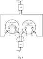
- FIG. 4 illustrates an exemplary parallel pump head cooling system, adapted according to another embodiment of the present disclosure.
- the system is configured substantially as described above in reference to FIG. 3 , only with the addition of a fluid divider 317 for dividing the coolant fluid into the first coolant stream 313 and the second coolant stream 315, and a fluid connector 319 for combining the two fluid streams after having passed through the coolant passageways 305, 307, 309, and 311 of the pump heads 301 and 303.
- Such parallel coolant flow patterns as described in FIGS. 3 and 4 decrease the average temperature difference between the pump heads, as compared with a serial coolant flow pattern, and provides more consistent compressibility and density for the fluids flowing between the pumps.
- This increased stability in temperature, compressibility, and density is especially desirable in CO 2 -based chromatography systems where the mobile phase includes CO 2 and varies greatly in density depending on the temperatures or temperature differences it is exposed to.
- FIG. 5 depicts a block diagram of an exemplary pump head cooling system, adapted according to one embodiment of the present disclosure.
- the coolant fluid is configured to cool four pump heads in a combination parallel/recursive fluid flow pattern.
- This system includes a first pump head 503 and a second pump head 505 configured with a recursive coolant fluid flow pattern and connected in parallel with a third pump head 507 and a fourth pump head 509, which are also fluidly coupled with a recursive coolant fluid flow pattern.
- two recursive flow patterns may be connected in parallel in order to effectively cool four pump heads, according to some embodiments.
- Coolant fluid stream 513 is directed to the first pump head 503 and the second pump head 505, which are cooled in a recursive coolant flow pattern, while the coolant fluid stream 515 is directed to the third pump head 507 and the fourth pump head 509, which are also cooled in a recursive coolant flow pattern.
- the two coolant fluid streams 513 and 515 are recombined in the fluid connector 511.
- the fluid connector 511 and/or fluid divider 501 may be a Y-connector, in some embodiments, or any other suitable fluid divider or connector that can separate a fluid stream into two fluid streams or combine two fluid streams into a single fluid stream.
- FIG. 6 is a flow chart of an exemplary method for providing substantially equal heat transfer between a coolant fluid and at least two pump heads, according to an embodiment of the present disclosure.
- the method includes flowing 601 a coolant fluid through a first pump head, and flowing 603 the coolant fluid through a second pump head.
- flowing the coolant fluid through the first and second pump heads may include flowing the coolant through a number of internal passageways within the pump heads.
- the method also includes, in this embodiment, providing 605 substantially equal heat transfer between the coolant fluid and the two pump heads.
- the coolant fluid gets progressively warmer as it passes through the first pump head and then through the second pump head, resulting in an average temperature difference of almost one degree Celsius (0.95°C) between the first pump head and the second pump head.
- This difference in temperature is caused, in part, by the coolant fluid being substantially warmer when cooling the second pump head compared to when it is cooling the first pump head.
- flowing the coolant fluid through the first pump head and the second pump head in a recursive or parallel flow pattern provides a substantially equal heat transfer between the coolant fluid and the two pump heads, which results in a decreased average temperature difference between the two pump heads.
- an average temperature difference of less than one degree Celsius (0.35°C for a recursive flow pattern and 0.45°C for a parallel flow pattern) may be achieved.
- the coolant fluid passes through the pump heads in a recursive or parallel flow pattern, rather than a serial flow pattern, the heat transfer between the coolant fluid and the pump heads is balanced. That is, the path of the coolant fluid through the first pump head and the second pump head, and any other pump head, is designed or adapted to provide a more balanced heat transfer. For example, the path is designed or adapted to account for a warming effect on the coolant as it passes through the various pumps.
- a coolant fluid flow pattern that produces a substantially equal heat between the coolant fluid and pump heads is one wherein the average temperature difference between the various pump heads is less than 0.95°C, less than 0.6°C, less than 0.5°C, less than 0.4°C, or less than 0.36°C.
- FIG. 7 is a flow chart of an exemplary method for cooling pump heads, according to an embodiment of the present disclosure.
- the method begins with determining 701 whether the coolant fluid is to be pre-chilled prior to cooling the pump heads. If the coolant is to be pre-chilled, the method continues with chilling 703 the coolant fluid using a suitable fluid chiller. The method then continues with determining 705 whether the pump head cooling system is a combination parallel and recursive system. If so, the coolant fluid is split 707 into two coolant streams and each coolant stream is recursively flowed 709 through its respective set of pump heads, as illustrated in FIG. 5 . After exiting the recursive flow patterns, the two coolant streams are then combined 711 again into a single coolant stream.
- the method continues with determining 713 whether the system is a parallel system. If not, the method continues with recursively flowing the coolant fluid through coolant passageways within the pump heads, as illustrated in FIGS. 1 and 2 . If the system is a parallel cooling system, the method continues with splitting 717 the coolant fluid into two coolant fluid streams and flowing 719 the coolant fluid streams in a parallel configuration through the coolant passageways of the pump heads, as illustrated in FIGS. 3 and 4 . After flowing 719 the coolant fluid streams in a parallel configuration through the coolant passageways of the pump heads, the method continues with combining 721 the coolant streams again into a single coolant stream. In some embodiments, flowing the coolant fluid through the passageways of the pump heads may be accomplished with one or more coolant pumps that can pump the coolant fluid through the cooling system 700.
- the techniques described above with respect to pumps used in CO 2 -based chromatography systems may be applicable to pumps used in other types of chromatography systems that include mobile phases that vary greatly in density with minor changes in temperature.
- a mobile phase including methanol at extremely high pressures may in some instances benefit from added temperature control.
- specific terminology is used for the sake of clarity. For purposes of description, each specific term is intended to at least include all technical and functional equivalents that operate in a similar manner to accomplish a similar purpose. Additionally, in some instances where a particular exemplary embodiment includes a plurality of system elements, device components or method steps, those elements, components or steps may be replaced with a single element, component or step.
- Exemplary flowcharts are provided herein for illustrative purposes and are nonlimiting examples of methods.
- One of ordinary skill in the art will recognize that exemplary methods may include more or fewer steps than those illustrated in the exemplary flowcharts, and that the steps in the exemplary flowcharts may be performed in a different order than the order shown in the illustrative flowcharts.
Landscapes
- Chemical & Material Sciences (AREA)
- Analytical Chemistry (AREA)
- Chemical Kinetics & Catalysis (AREA)
- Physics & Mathematics (AREA)
- Engineering & Computer Science (AREA)
- General Physics & Mathematics (AREA)
- Biochemistry (AREA)
- General Health & Medical Sciences (AREA)
- Life Sciences & Earth Sciences (AREA)
- Immunology (AREA)
- Pathology (AREA)
- Health & Medical Sciences (AREA)
- Mechanical Engineering (AREA)
- Thermal Sciences (AREA)
- General Engineering & Computer Science (AREA)
- Cooling Or The Like Of Electrical Apparatus (AREA)
- Physical Or Chemical Processes And Apparatus (AREA)
Description
- This application claims priority to
U.S. Provisional Patent Application Serial No. 62/145,837 - The present disclosure relates to techniques for cooling of pump heads in carbon dioxide chromatography systems. The present disclosure also relates to methodologies, systems and apparatus for providing a substantially equal heat transfer from each of at least two pump heads.
- In general, multiple pumps may be arranged in a parallel or serial fashion to pump fluids in a fluid chromatography system. Chromatography involves the flowing of a mobile phase over a stationary phase to effect separation. To speed-up and enhance the efficiency of the separation, pressurized mobile phases were introduced. Carbon dioxide based chromatographic systems use CO2 as a component of the mobile phase flow stream, and the CO2 based mobile phase is delivered from the pumps and carried through the separation column as a pressurized liquid. In systems using CO2 as a mobile phase component, one challenge is pumping the CO2, as small changes in temperature and/or pressure greatly change the density of CO2. Any fluctuation in the density of the CO2 elevates compressibility issues, frustrating typical compressibility compensation schemes. Therefore, a need exists for chromatography systems that provide increased stability and control of temperature and pressure levels.
- The following documents are known:
-
US 4,990,250 A (HELLINGER L) February 5, 1991 ; entire document, -
US 2006/0180300 A1 (LENEHAN DJ et al.) August 17, 2006 ; entire document, -
US 5,094,753 A (ALLINGTON RW et al.) March 10, 1992 ; entire document, -
DE 20 2010 015 306 U1 (LEWA GmbH) February 10, 2011; entire document, -
US 5,750,029 A (HOUCK RK et al.) May 12, 1998 ; entire document, -
US 2014/0190183 A1 (BERGER TA et al). July 10, 2014 ; entire document, -
WO 2012/122361 A2 (WATERS TECHNOLOGIES CORP [US]; JOUDREY KURT D [US]); LINDERSON PAUL E [) 13 September 2012 (2012-09-13)
*claim 33;figure 7 *, -
WO 2012/099763 A1 (WATERS TECHNOLOGIES CORP [US]; JOUDREY KURT [US]); LINDERSON PAUL E [) 26 July 2012 (2012-07-26)
*paragraphs [0030] - [0032]; claim 9;figure 2 *. This document discloses a system and a method of cooling a pump head used in chromatography. -
EP 0 672 831 A2 (ISCO INC [US])
20 September 1995 (1995-09-20)
*claims 1,25*, - HANCOCK S A: "A NOVEL DEVICE FOR COOLING HPLC PUMP HEADS PUMPING SUPERCRITICAL FLUIDS",
JOURNAL OF HIGH RESOLUTION CHROMATOGRAPHY,
WILEY VCH, WEINHEIM, DE,
vol. 17, no. 11,
1 November 1994 (1994-11-01), page 795/796, XP000485681,
ISSN: 0935-6304, DOI:
10.1002/JHRC.1240171113
*the whole document*, - The present invention is disclosed in the claims and relates to embodiments directed to pump head cooling systems for providing balanced cooling and heat transfer between multiple pump heads. Further, the embodiments are related to methodologies, systems and apparatus for pump head cooling systems that employ recursive or parallel coolant flow patterns to achieve a substantially equal average heat transfer between the pump heads and the coolant fluid. In particular, some embodiments are related to fluid cooling systems for cooling pump heads that are used in a CO2-based chromatography systems, i.e., a chromatography system in which the mobile phase includes CO2.
- In one aspect, the present technology relates to a pump head cooling system. The system includes a first pump head defining a first coolant passageway and a second coolant passageway, each passageway having an inlet into the first pump head and an outlet out of the first pump head. The system also includes a second pump head defining a third coolant passageway and a fourth coolant passageway, each passageway having an inlet into the second pump head and an outlet out of the second pump head. In the system, the outlet of the first coolant passageway is fluidly coupled to the inlet of the third coolant passageway, the outlet of the third coolant passageway is fluidly coupled to the inlet of the fourth coolant passageway, and the outlet of the fourth coolant passageway is fluidly coupled to the inlet of the second coolant passageway.
- Embodiments of this aspect of the technology can include one or more of the following features. In some embodiments, the first pump head and the second pump head are composed of, or composed in part of, stainless steel. In some embodiments, the first pump head and the second pump head are adapted to operate at flow rates between 0.50 - 150.00 mL/min. In some embodiments, the first pump head and the second pump head are adapted to operate at pressures up to 50 MPa. In some embodiments, the system also includes a coolant pump adapted to pump a coolant fluid through the first coolant passageway, the second coolant passageway, the third coolant passageway, and the fourth coolant passageway. In some embodiments, the system also includes a fluid chiller adapted to chill a coolant fluid prior to pumping the coolant fluid through the first coolant passageway. In some embodiments, the system also includes: a first coolant tube adapted to fluidly couple the outlet of the first coolant passageway to the inlet of the third coolant passageway, a second coolant tube adapted to fluidly couple the outlet of the third coolant passageway to the inlet of the fourth coolant passageway, and a third coolant tube adapted to fluidly couple the outlet of the fourth coolant passageway to the inlet of the second coolant passageway.
- According to another aspect, the present technology relates to a pump head cooling system. The system includes a first pump head defining a first coolant passageway and a second coolant passageway, each passageway having an inlet into the first pump head and an outlet out of the first pump head, and wherein the outlet of the first coolant passageway is fluidly coupled to the inlet of the second coolant passageway. The system also includes a second pump head defining a third coolant passageway and a fourth coolant passageway, each passageway having an inlet into the second pump head and an outlet out of the second pump head, and wherein the outlet of the third coolant passageway is fluidly coupled to the inlet of the fourth coolant passageway. The system also includes at least one coolant pump adapted to pump a first stream of coolant fluid through the first pump head and pump a second stream of coolant fluid through the second pump head, such that an average heat transfer between the first pump head and the first stream of coolant fluid is substantially equal to an average heat transfer between the second pump head and the second stream of coolant fluid.
- Embodiments of this aspect of the technology can include one or more of the following features. In some embodiments, the system also includes a first fluid connector having one inlet and two outlets, wherein a first outlet is fluidly coupled to an entrance of the first coolant passageway and a second outlet is fluidly coupled to an entrance of the third coolant passageway. In some embodiments, the system also includes a fluid connector having two inlets and a single outlet, wherein a first inlet is fluidly coupled to an outlet of the second coolant passageway and a second inlet is fluidly coupled to an outlet of the fourth coolant passageway. In some embodiments, the system also includes a fluid chiller adapted to chill the first stream of coolant fluid and the second stream of coolant fluid after exiting the coolant pump. In some embodiments, the system also includes a control system adapted to measure a temperature of the first pump head and a temperature of the second pump head and apply cooling to the pump head cooling system to maintain a temperature difference between the first pump head and the second pump head below 1.0 degree Celsius.
- According to another aspect, the present technology relates to a method of cooling pump heads. The method includes flowing at least one stream of coolant fluid through a plurality of coolant passageways within a first pump head and a second pump head along a coolant fluid path. The method also includes providing an average heat transfer between the first pump head and the coolant fluid that is substantially equal to an average heat transfer between the second pump head and the coolant fluid.
- Embodiments of the above aspect can include one or more of the following features. In some embodiments, the method also includes maintaining a temperature difference between the first pump head and the second pump head below 1.0 degree Celsius. In some embodiments, the method also includes maintaining the temperature difference between the first pump head and the second pump head below 0.5 degrees Celsius. In some embodiments, maintaining the temperature difference between the first pump head and the second pump head below 0.4 degrees Celsius. In some embodiments, the method also includes chilling the at least one stream of coolant fluid prior to flowing through the plurality of coolant passageways. In some embodiments, flowing at least one stream of coolant fluid includes: flowing a first coolant stream through a first coolant passageway within the first pump head, flowing the first coolant stream from an outlet of the first coolant passageway through a second coolant passageway within the second pump head, flowing the first coolant stream from an outlet of the second coolant passageway through a third coolant passageway within the second pump head, and flowing the first coolant fluid from an outlet of the third coolant passageway through a fourth coolant passageway within the first pump head. In some embodiments, flowing at least one stream through a plurality of coolant passageways includes: flowing a first stream of coolant fluid from a coolant fluid source through a first coolant passageway within a first pump head, wherein the first coolant passageway has an inlet into the first pump head and an outlet out of the first pump head, flowing the first stream of coolant fluid from the outlet of the first coolant passageway to an inlet of a second coolant passageway within the first pump head, wherein the second coolant passageway has an inlet into the first pump head and an outlet out of the first pump head, flowing a second stream of coolant fluid from the coolant fluid source through a third coolant passageway within a second pump head, wherein the third coolant passageway has an inlet into the second pump head and an outlet out of the second pump head, and flowing the second stream of coolant fluid from the outlet of the third coolant passageway to an inlet of a fourth coolant passageway within the second pump head, wherein the fourth coolant passageway has an inlet into the second pump head and an outlet out of the second pump head, wherein the temperature differential between the first stream of coolant fluid upon exiting the second coolant passageway and the second stream of coolant fluid upon exiting the fourth coolant passageway is less than 1.0 degree Celsius. In some embodiments, the method also includes separating the coolant fluid from a single coolant fluid source into the first stream of coolant fluid and the second stream of coolant fluid. In some embodiments, the method also includes combining the first stream of coolant fluid and the second stream of coolant fluid into a single stream after flowing the first stream through the second coolant passageway and flowing the second stream through the fourth coolant passageway.
- The present disclosure provides a number of advantages over current methods, systems and apparatus. For instance, providing a balanced average heat transfer between the pump heads will result in more stable compressibility and density properties for fluids, especially highly compressible fluids, such as CO2 or Freon, being pumped by the pumps. This increased stability in temperature, compressibility, and density is particularly useful in CO2-based chromatography systems where the density of the CO2 varies greatly based on temperature.
- The foregoing and other features and advantages provided by the present disclosure will be more fully understood from the following description of exemplary embodiments when read together with the accompanying drawings, in which:
-
FIG. 1 illustrates an exemplary recursive pump head cooling system, according to one embodiment of the present disclosure. -
FIG. 2 illustrates an exemplary recursive pump head cooling system, adapted according to another embodiment of the present disclosure. -
FIG. 3 illustrates an exemplary parallel pump head cooling system, adapted according to another embodiment of the present disclosure. -
FIG. 4 illustrates an exemplary parallel pump head cooling system, adapted according to another embodiment of the present disclosure. -
FIG. 5 depicts a block diagram of an exemplary pump head cooling system, adapted according to one embodiment of the present disclosure. -
FIG. 6 is a flow chart of an exemplary method for providing substantially equal heat transfer between a coolant fluid and at least two pump heads, according to one embodiment of the present disclosure. -
FIG. 7 is a flow chart of an exemplary method for cooling pump heads, according to an embodiment of the present disclosure. - Provided herein are methodologies, systems, and apparatus for cooling pump heads to provide a balanced level of heat transfer between the pump heads. In chromatography systems, a mobile phase is typically delivered using multiple pumps in a serial or parallel fashion. CO2-based chromatography systems differ from other forms of chromatography in that the mobile phase includes CO2. In general, the CO2 or CO2 mixture (e.g. CO2 mixed with a solvent such as methanol) is used in a supercritical or near supercritical fluid state, and suitable temperature and pressure levels must be maintained. While pumping the mobile phase, the pump heads themselves may be cooled in order to prevent heating of the mobile phase, which may cause unwanted changes in the density of the CO2. Because a mobile phase containing CO2 differs greatly in density at different temperatures, it is important to maintain a consistent temperature between the pumps. The difference in temperature between the multiple pump heads may be reduced by using a heat exchange fluid or coolant of a given temperature that is in contact with each of the pump heads within the multi-pump system. This may be accomplished by flowing a coolant fluid through passageways within each of the pump heads in a parallel or recursive flow pattern.
- To reduce the temperature difference between multiple pump heads, a balanced cooling system is disclosed which provides a substantially equal average heat transfer between each of the pump heads and the coolant fluid. As provided herein, the coolant fluid flows through a number of coolant passageways within each pump head in a parallel or recursive pattern in order to provide balanced cooling to each pump head and prevent density differences between the mobile phase fluids being pumped by each of the pump heads.
- In a recursive coolant flow pattern, the coolant fluid first passes through a coolant passageway within the first pump head, and then through a coolant passageway within the second pump head to provide the novel balancing of temperatures between pumps that is to provide substantially equal heat transfer between multiple pumps used in a fluid system. Because the coolant fluid was at its coldest temperature when it initially passed through the first pump head, the coolant fluid is then transferred to the second pump head before passing through a second coolant passageway within the first pump head (the first pump head includes a first and second coolant passageway). Thus, the first pump head comes in contact with the coolant fluid at its coldest and warmest temperatures, while the second pump head comes in contact with the coolant fluid in the intermediate temperature stages, thus providing a more balanced cooling effect between the two pump heads. As will be appreciated, the recursive flow pattern may be implemented with three, four, or any number of pump heads.
- In a parallel coolant flow pattern in accordance with the present technology, the coolant fluid is divided into two different coolant fluid streams of substantially equal temperature, which are each directed through the coolant passageways within one of the first or second pump heads. In other embodiments, a balanced pump head cooling system may involve dividing a coolant fluid into two coolant fluid streams, each of which is used to recursively cool two or more pump heads. Thus, two or more recursive cooling patterns may be connected in parallel. As will be appreciated, any number of combinations of parallel and/or recursive coolant flow patterns may be implemented, and the present disclosure is not intended to be limited to any particular configuration, number of pump heads, or number of coolant fluid streams.
- In some embodiments, the pump head materials that come in contact with the mobile phase may include, for example, stainless steel, sapphire, ultra high molecular weight polyethylene (UHMWPE), ruby, ethylene tetrafluoroethylene (ETFE), ceramic, fluorocarbon polymer, polyether ether ketone (PEEK), or other suitable materials. The pump head may have a flow rate range of between about 0.50-150.00 mL/min, in some embodiments. In other embodiments, the flow rate may be as high as 350 mL/min. The flow rate may be adjustable in increments of as low as 0.01 mL/min, in some embodiments. The pumps may operate at pressures as high as 50 MPa, in some embodiments. In one specific example, the pumps may be binary gradient module (BGM) 2545 pumps that can be used as a primary solvent delivery device for a preparative or analytical chromatography system. Such pumps may provide smooth pulse-free flow for both analytical and preparative chromatography systems.
- Table 1 below provides test results from a two-pump system operating at ambient temperature (23°C) and chilled using a Thermo Scientific™ RTE 7 refrigerated bath chiller set to 4°C. In this example, the two pump heads, identified as a right pump head and a left pump head, were cooled by flowing a coolant fluid in a serial (e.g., the coolant passes from the first pump to the second pump), recursive, and parallel flow pattern through fluid passageways at two locations within each pump head. The temperature at the first location in the left pump head is indicated as L1, the temperature at the first location in the right pump head is indicated as R1, the temperature at the second location of the left pump head is indicated as L2, and the temperature at the second location of the right pump head is indicated as R2.
Table 1 Configuration Temperature T1 (°C) Temperature T2 (°C) Ave. (°C) L1 R1 R1-L1 L2 R2 R2-L2 R-L Serial 7.3 8.4 1.1 11.0 11.8 0.8 0.95 Recursive 7.3 7.6 0.3 11.1 11.5 0.4 0.35 Parallel with Y-Connector 7.5 8.1 0.6 11.3 11.6 0.3 0.45 - As can be seen in Table 1, when the pump heads are cooled using a serial coolant fluid flow pattern, the difference in temperature between the right pump head and the left pump head at the first location (R1-L1) is measured at 1.1°C, and the difference in temperature between the right pump head and the left pump head at the second location (R2-L2) is measured at 0.8°C. Thus, the average difference in temperature between the right pump head and the left pump head is about 0.95°C, which can result in significant differences in the density of a CO2-based mobile phase between the two pump heads.
- In contrast, when the pump heads are cooled using a recursive coolant fluid flow pattern, the difference in temperature between the right pump head and the left pump head at the first location (R1-L1) is 0.3°C, and the difference in temperature between the right pump head and the left pump head at the second location (R2-L2) is 0.4°C. This results in an average difference in temperature between the right pump head and the left pump head of about 0.35°C, which is less than half the temperature difference provided by the serial coolant fluid flow pattern. Similarly, when the pump heads are cooled using a parallel coolant fluid flow pattern, the difference in temperature between the right pump head and the left pump head at the first location (R1-L1) is 0.6°C, and the difference in temperature between the right pump head and the left pump head at the second location (R2-L2) is 0.3°C. This results in an average difference in temperature between the right pump head and the left pump head of about 0.45°C. Although examples are provided with two pump heads, the same techniques and advantages may be obtained when cooling more than two pump heads, according to exemplary embodiments of the present disclosure.
-
FIG. 1 illustrates an exemplary recursive pump head cooling system, according to one embodiment of the present disclosure. The system includes afirst pump head 101, having afirst coolant passageway 105 and asecond coolant passageway 107, and asecond pump head 103, having afirst coolant passageway 109 and asecond coolant passageway 111. As illustrated in the following figures, the dotted lines (105, 107, 109, 111, etc.) indicate coolant passageways that pass through an internal portion of the pump heads. Thecoolant fluid 113 is initially flowed to an entrance of thefirst coolant passageway 105 of thefirst pump head 101. At this point, thecoolant fluid 113 is at its coolest temperature because it has not yet been subjected to heat transfer from either of the pump heads. After flowing out of thefirst coolant passageway 105 of the first pump head, the coolant fluid is flowed to thefirst coolant passageway 109 of thesecond pump head 103. The coolant fluid exits thefirst coolant passageway 109, exiting thesecond pump head 103, and subsequently re-enters thesecond pump head 103 at an entrance of thesecond coolant passageway 111 of thesecond pump head 103. Finally, after exiting thesecond coolant passageway 111 of thesecond pump head 103, the coolant fluid is flowed to an entrance of thesecond coolant passageway 107 of thefirst pump head 101. At this point, thecoolant fluid 113 is at its warmest temperature because it has already been subjected to heat transfer from thefirst coolant passageway 105 of the first pump head, as well as bothcoolant passageways second pump head 103. Thus, a more balanced average heat transfer is achieved between the two pump heads by cooling thefirst pump head 101 with thecoolant fluid 113 while it is at its coolest and warmest points. In some embodiments, such a recursive flow pattern may provide a balanced cooling system such that the average temperature difference between the first pump head and the second pump head is below 1.0°C, 0.5°C, or 0.4°C. - The system may also include a
first coolant tube 115 that fluidly couples thefirst coolant passageway 105 of thefirst pump head 101 with thefirst coolant passageway 109 of thesecond pump head 103, asecond coolant tube 117 that fluidly couples thefirst coolant passageway 109 of thesecond pump head 103 with thesecond coolant passageway 111 of thesecond pump head 103, and athird coolant tube 119 that fluidly couples thesecond coolant passageway 111 of thesecond pump head 103 with thesecond coolant passageway 107 of thefirst pump head 101. The coolant tubes may be insulated coolant tubes, in some embodiments. In addition, thesecoolant tubes - As discussed above, cooling the pump heads in a more balanced way will result in a more stable temperature between the pump heads and a more constant compressibility and density between the fluids being pumped by the pumps. This is especially desirable in CO2-based chromatography systems where the mobile phase includes CO2 and varies greatly in density depending on the temperature it is exposed to.
-
FIG. 2 illustrates an exemplary recursive pump head cooling system, adapted according to another embodiment of the present disclosure. This particular system includes afirst pump head 201 having afirst coolant passageway 207 and asecond coolant passageway 209, asecond pump head 203 having afirst coolant passageway 211 and asecond coolant passageway 213, and athird pump head 205 having afirst coolant passageway 215 and asecond coolant passageway 217. In this particular example, thecoolant fluid 219 initially flows through thefirst coolant passageway 207 of thefirst pump head 201, then through thefirst coolant passageway 211 of thesecond pump head 203, and then through thefirst coolant passageway 215 of thethird pump head 205. After flowing through thefirst coolant passageway 215 of thethird pump head 205, thecoolant fluid 219 is exits thethird pump head 205 and re-enters at an entrance of thesecond coolant passageway 217 of thethird pump head 205. After exiting thesecond coolant passageway 217 of thethird pump head 205, thecoolant fluid 219 is flowed to through thesecond coolant passageway 213 of thesecond pump head 203, and finally through thesecond coolant passageway 209 of thefirst pump head 201. Thus, a more balanced average heat transfer is achieved between the coolant fluid and the three pump heads 201, 203, and 205. -
FIG. 3 illustrates an exemplary parallel pump head cooling system, adapted according to another embodiment of the present disclosure. This particular system includes afirst pump head 301 having afirst coolant passageway 305 and asecond coolant passageway 307, and asecond pump head 303 having afirst coolant passageway 309 and asecond coolant passageway 311. In contrast to the recursive coolant fluid flow pattern, the parallel coolant flow patter includes two coolant fluid streams 313 and 315. A firstcoolant fluid stream 313 is directed to thefirst pump head 301 and passes through thefirst coolant passageway 305. After exiting thefirst pump head 301 at the outlet of thefirst coolant passageway 305, the firstcoolant fluid stream 313 re-enters thefirst pump head 301 at an inlet of thesecond coolant passageway 307. Meanwhile, the secondcoolant fluid stream 315 is directed to thesecond pump head 303 and passes through thefirst coolant passageway 309. After exiting thesecond pump head 303 at the outlet of thefirst coolant passageway 309, the secondcoolant fluid stream 315 re-enters thesecond pump head 303 at an inlet of thesecond coolant passageway 311. In this particular example, the firstcoolant fluid stream 313 and the secondcoolant fluid stream 315 are both initially cooled to substantially the same temperature, and they may be pumped using a single coolant pump. -
FIG. 4 illustrates an exemplary parallel pump head cooling system, adapted according to another embodiment of the present disclosure. In this particular embodiment, the system is configured substantially as described above in reference toFIG. 3 , only with the addition of afluid divider 317 for dividing the coolant fluid into thefirst coolant stream 313 and thesecond coolant stream 315, and afluid connector 319 for combining the two fluid streams after having passed through thecoolant passageways - Such parallel coolant flow patterns as described in
FIGS. 3 and4 decrease the average temperature difference between the pump heads, as compared with a serial coolant flow pattern, and provides more consistent compressibility and density for the fluids flowing between the pumps. This increased stability in temperature, compressibility, and density is especially desirable in CO2-based chromatography systems where the mobile phase includes CO2 and varies greatly in density depending on the temperatures or temperature differences it is exposed to. -
FIG. 5 depicts a block diagram of an exemplary pump head cooling system, adapted according to one embodiment of the present disclosure. In this example system, the coolant fluid is configured to cool four pump heads in a combination parallel/recursive fluid flow pattern. This system includes afirst pump head 503 and asecond pump head 505 configured with a recursive coolant fluid flow pattern and connected in parallel with athird pump head 507 and afourth pump head 509, which are also fluidly coupled with a recursive coolant fluid flow pattern. Thus, two recursive flow patterns may be connected in parallel in order to effectively cool four pump heads, according to some embodiments. The pump head cooling system ofFIG. 5 includes afluid divider 501 that receives a coolant stream and divides it into twostreams Coolant fluid stream 513 is directed to thefirst pump head 503 and thesecond pump head 505, which are cooled in a recursive coolant flow pattern, while thecoolant fluid stream 515 is directed to thethird pump head 507 and thefourth pump head 509, which are also cooled in a recursive coolant flow pattern. After exiting their respective recursive flow patterns, the two coolant fluid streams 513 and 515 are recombined in thefluid connector 511. Thefluid connector 511 and/orfluid divider 501 may be a Y-connector, in some embodiments, or any other suitable fluid divider or connector that can separate a fluid stream into two fluid streams or combine two fluid streams into a single fluid stream. -
FIG. 6 is a flow chart of an exemplary method for providing substantially equal heat transfer between a coolant fluid and at least two pump heads, according to an embodiment of the present disclosure. In this particular embodiment, the method includes flowing 601 a coolant fluid through a first pump head, and flowing 603 the coolant fluid through a second pump head. As described above with reference toFIGS. 1-4 , flowing the coolant fluid through the first and second pump heads may include flowing the coolant through a number of internal passageways within the pump heads. The method also includes, in this embodiment, providing 605 substantially equal heat transfer between the coolant fluid and the two pump heads. As discussed above in reference to Table 1, when two pump heads are cooled using a serial coolant flow pattern, the coolant fluid gets progressively warmer as it passes through the first pump head and then through the second pump head, resulting in an average temperature difference of almost one degree Celsius (0.95°C) between the first pump head and the second pump head. This difference in temperature is caused, in part, by the coolant fluid being substantially warmer when cooling the second pump head compared to when it is cooling the first pump head. In some embodiments of the present disclosure, flowing the coolant fluid through the first pump head and the second pump head in a recursive or parallel flow pattern provides a substantially equal heat transfer between the coolant fluid and the two pump heads, which results in a decreased average temperature difference between the two pump heads. Specifically, in the example described in Table 1, an average temperature difference of less than one degree Celsius (0.35°C for a recursive flow pattern and 0.45°C for a parallel flow pattern) may be achieved. Because the coolant fluid passes through the pump heads in a recursive or parallel flow pattern, rather than a serial flow pattern, the heat transfer between the coolant fluid and the pump heads is balanced. That is, the path of the coolant fluid through the first pump head and the second pump head, and any other pump head, is designed or adapted to provide a more balanced heat transfer. For example, the path is designed or adapted to account for a warming effect on the coolant as it passes through the various pumps. The substantially equal heat transfer between the coolant fluid and the two pump heads is responsible, in part, for the increased temperature uniformity between the pump heads. In some embodiments, a coolant fluid flow pattern that produces a substantially equal heat between the coolant fluid and pump heads is one wherein the average temperature difference between the various pump heads is less than 0.95°C, less than 0.6°C, less than 0.5°C, less than 0.4°C, or less than 0.36°C. -
FIG. 7 is a flow chart of an exemplary method for cooling pump heads, according to an embodiment of the present disclosure. In this particular embodiment, the method begins with determining 701 whether the coolant fluid is to be pre-chilled prior to cooling the pump heads. If the coolant is to be pre-chilled, the method continues with chilling 703 the coolant fluid using a suitable fluid chiller. The method then continues with determining 705 whether the pump head cooling system is a combination parallel and recursive system. If so, the coolant fluid is split 707 into two coolant streams and each coolant stream is recursively flowed 709 through its respective set of pump heads, as illustrated inFIG. 5 . After exiting the recursive flow patterns, the two coolant streams are then combined 711 again into a single coolant stream. - If, however, the pump head cooling system is not a combination parallel and recursive system, the method continues with determining 713 whether the system is a parallel system. If not, the method continues with recursively flowing the coolant fluid through coolant passageways within the pump heads, as illustrated in
FIGS. 1 and2 . If the system is a parallel cooling system, the method continues with splitting 717 the coolant fluid into two coolant fluid streams and flowing 719 the coolant fluid streams in a parallel configuration through the coolant passageways of the pump heads, as illustrated inFIGS. 3 and4 . After flowing 719 the coolant fluid streams in a parallel configuration through the coolant passageways of the pump heads, the method continues with combining 721 the coolant streams again into a single coolant stream. In some embodiments, flowing the coolant fluid through the passageways of the pump heads may be accomplished with one or more coolant pumps that can pump the coolant fluid through thecooling system 700. - In alternative embodiments, the techniques described above with respect to pumps used in CO2-based chromatography systems may be applicable to pumps used in other types of chromatography systems that include mobile phases that vary greatly in density with minor changes in temperature. For example, a mobile phase including methanol at extremely high pressures may in some instances benefit from added temperature control. In describing exemplary embodiments, specific terminology is used for the sake of clarity. For purposes of description, each specific term is intended to at least include all technical and functional equivalents that operate in a similar manner to accomplish a similar purpose. Additionally, in some instances where a particular exemplary embodiment includes a plurality of system elements, device components or method steps, those elements, components or steps may be replaced with a single element, component or step. Likewise, a single element, component or step may be replaced with a plurality of elements, components or steps that serve the same purpose. Moreover, while exemplary embodiments have been shown and described with references to particular embodiments thereof, those of ordinary skill in the art will understand that various substitutions and alterations in form and detail may be made therein without departing from the scope of the invention. Further still, other aspects, functions and advantages are also within the scope of the invention.
- Exemplary flowcharts are provided herein for illustrative purposes and are nonlimiting examples of methods. One of ordinary skill in the art will recognize that exemplary methods may include more or fewer steps than those illustrated in the exemplary flowcharts, and that the steps in the exemplary flowcharts may be performed in a different order than the order shown in the illustrative flowcharts.
Claims (15)
- A pump head cooling system for a carbon dioxide chromatography system, comprising:a first pump head (101, 201, 301, 503) defining a first coolant passageway (105, 207, 305) and a second coolant passageway (107, 209,307), each passageway having an inlet into the first pump head (101, 201, 301, 503) and an outlet out of the first pump head (101, 201, 301,503); anda second pump head (103, 203, 303, 505) defining a third coolant passageway (109, 211, 309) and a fourth coolant passageway (111, 213, 311), each passageway having an inlet into the second pump head (103, 203, 303, 505) and an outlet out of the second pump head 103, 203, 303, 505);wherein the outlet of the first coolant passageway (105, 207, 305) is fluidly coupled to the inlet of the third coolant passageway (109, 211, 309), the outlet of the third coolant passageway (109, 211, 309) is fluidly coupled to the inlet of the fourth coolant passageway (111, 213, 311), and the outlet of the fourth coolant passageway (111, 213, 311) is fluidly coupled to the inlet of the second coolant passageway (107, 209, 307).
- The pump head cooling system of claim 1, wherein the first pump head (101, 201, 301, 503) and the second pump (103, 203, 303, 505) head are: composed of stainless steel; adapted to operate at flow rates between 0.50 - 150.00 mL/min; and/or adapted to operate at pressures up to 50 MPa.
- The pump head cooling system of claim 1, further comprising a coolant pump adapted to pump a coolant fluid through the first coolant passageway (105, 207, 305), the second coolant passageway (107, 209, 307), the third coolant passageway (109, 211, 309), and the fourth coolant passageway (111, 213, 311), preferably further comprising a fluid chiller adapted to chill a coolant fluid prior to pumping the coolant fluid through the first coolant passageway (105, 207, 305).
- The pump head cooling system of claim 1, further comprising:a first coolant tube (115) adapted to fluidly couple the outlet of the first coolant passageway (105, 207, 305) to the inlet of the third coolant passageway (109, 211, 309);a second coolant tube (117) adapted to fluidly couple the outlet of the third coolant passageway (109, 211, 309) to the inlet of the fourth coolant passageway (111, 213, 311); anda third coolant tube (119) adapted to fluidly couple the outlet of the fourth coolant passageway (111, 213, 311) to the inlet of the second coolant passageway (107, 209, 307).
- A pump head cooling system for a carbon dioxide chromatography system, comprising:a first pump head (101, 201. 301, 503) defining a first coolant passageway (105, 207, 305) and a second coolant passageway (107, 209, 307), each passageway having an inlet into the first pump head (101, 201, 301, 503) and an outlet out of the first pump head (101, 201, 301, 503), and wherein the outlet of the first coolant passageway (105, 207, 305) is fluidly coupled to the inlet of the second coolant passageway (107, 209, 307);a second pump head (103), 203, 303, 505) defining a third coolant passageway (109, 211, 309) and a fourth coolant passageway (111, 213, 311), each passageway having an inlet into the second pump head (103, 207, 303, 505) and an outlet out of the second pump head (103, 203, 303, 505), and wherein the outlet of the third coolant passageway (109, 211, 309) is fluidly coupled to the inlet of the fourth coolant passageway (111, 213, 311); and at least one coolant pump adapted to pump a first stream of coolant fluid through the first pump head (107, 209, 307) and pump a second stream of coolant fluid through the second pump head (103, 203, 303, 505), such that an average heat transfer between the first pump head (107, 209, 307) and the first stream of coolant fluid is substantially equal to an average heat transfer between the second pump head (103, 203, 303, 505) and the second stream of coolant fluid.
- The system of claim 5, further comprising a first fluid connector (317) having one inlet and two outlets, wherein a first outlet is fluidly coupled to an entrance of the first coolant passageway (305) and a second outlet is fluidly coupled to an entrance of the third coolant passageway (309).
- The system of claim 5, further comprising a fluid connector (319) having two inlets and a single outlet, wherein a first inlet is fluidly coupled to an outlet of the second coolant passageway (307) and a second inlet is fluidly coupled to an outlet of the fourth coolant passageway (311).
- The pump head cooling system of claim 5, further comprising a fluid chiller adapted to chill the first stream of coolant fluid and the second stream of coolant fluid after exiting the coolant pump.
- The pump head cooling system of claim 5, further comprising a control system adapted to measure a temperature of the first pump head (101, 201, 301, 503) and a temperature of the second pump head (103, 203, 303, 503) and apply cooling to the pump head cooling system to maintain a temperature difference between the first pump head (101, 201, 301, 503) and the second pump head (103, 203, 303, 505) below 1.0 degree Celsius.
- A method of operating a cooling system according to claim 1 or claim 5, comprising:flowing at least one stream of coolant fluid through the plurality of coolant passageways (105, 207, 305, 107, 209, 307, 109, 211, 309, 111, 213, 311) within
the first pump head (101, 201, 301, 503) and the second pump head (103, 203, 303, 505) along a coolant fluid path; andproviding an average heat transfer between the first pump head (101, 201, 301, 503) andthe coolant fluid that is substantially equal to an average heat transfer between the second pump head (103, 203, 303, 505) and the coolant fluid. - The method of claim 10, further comprising maintaining a temperature difference between the first pump head (101, 201, 301, 503) and the second pump head (103, 203, 303, 505) below 1.0 degree Celsius, preferably below 0.5 degrees Celsius, preferably below 0.4 degrees Celsius.
- The method of claim 10, further comprising chilling the at least one stream of coolant fluid prior to flowing through the plurality of coolant passageways (105, 207, 305, 107, 209, 307, 109, 211, 309, 111, 213, 311).
- The method of claim 10, wherein flowing at least one stream of coolant fluid comprises:flowing a first coolant stream through the first coolant passageway (105, 207, 305) within the first pump head (101, 201, 301, 503);flowing the first coolant stream from the outlet of the first coolant passageway (105, 207, 305) through the second coolant passageway (109, 211, 309) within the second pump head (103, 203, 303, 503);flowing the first coolant stream from the outlet of the second coolant passageway (109, 211, 309) through the third coolant passageway (111, 213, 311) within the second pump head (103, 203, 303, 503); andflowing the first coolant fluid from the outlet of the third coolant passageway (111, 213, 311) through the fourth coolant passageway (107, 209, 303) within the first pump head (101, 201, 301, 503).
- The method of claim 10, wherein flowing at least one stream through a plurality of coolant passageways comprises:flowing a first stream of coolant fluid from a coolant fluid source through the first coolant passageway (105, 207, 305) within the first pump head (101, 201, 301, 503), wherein the first coolant passageway (105, 207, 305) has an inlet into the first pump head (101, 201, 301, 503) and an outlet out of the first pump head (101, 201, 301, 503);flowing the first stream of coolant fluid from the outlet of the first coolant passageway (105, 207, 305) to the inlet of the second coolant passageway (107, 209, 307) within the first pump head (101, 201, 301, 503), wherein the second coolant passageway (107, 209, 307) has an inlet into the first pump head (101, 201, 301, 503) and an outlet out of the first pump head (101, 201, 301, 503); flowing a second stream of coolant fluid from the coolant fluid source through the third coolant passageway (109, 211, 309) within the second pump head (103, 203, 303, 505),wherein the third coolant passageway (109, 211, 309) has an inlet into the second pump head (103, 203, 303, 505) and an outlet out of the second pump head (103, 203, 303, 505); and
flowing the second stream of coolant fluid from the outlet of the third coolant passageway (109, 211, 309) to the inlet of the fourth coolant passageway (111, 213, 311)within the second pump head (103, 203, 303, 505) wherein the fourth coolant passageway(111, 213, 311) has an inlet into the second pump head (103, 203, 303, 505) and an outlet out of the second pump head (103, 203, 303, 505);
wherein the temperature differential between the first stream of coolant fluid upon exiting the second coolant passageway (107, 209, 307) and the second stream of coolant fluid upon exiting the fourth coolant passageway (111, 213, 311) is less than 1.0 degree Celsius. - The method of claim 14, further comprising separating the coolant fluid from a single coolant fluid source into the first stream of coolant fluid and the second stream of coolant fluid, or further comprising combining the first stream of coolant fluid and the second stream of coolant fluid into a single stream after flowing the first stream through the second coolant passageway (107, 209, 307) and flowing the second stream through the fourth coolant passageway (111, 213, 311).
Applications Claiming Priority (2)
| Application Number | Priority Date | Filing Date | Title |
|---|---|---|---|
| US201562145837P | 2015-04-10 | 2015-04-10 | |
| PCT/US2016/026386 WO2016164544A1 (en) | 2015-04-10 | 2016-04-07 | Cooling of pump heads in carbon dioxide chromatography systems |
Publications (3)
| Publication Number | Publication Date |
|---|---|
| EP3280507A1 EP3280507A1 (en) | 2018-02-14 |
| EP3280507A4 EP3280507A4 (en) | 2019-02-06 |
| EP3280507B1 true EP3280507B1 (en) | 2020-05-27 |
Family
ID=57072908
Family Applications (1)
| Application Number | Title | Priority Date | Filing Date |
|---|---|---|---|
| EP16777256.5A Active EP3280507B1 (en) | 2015-04-10 | 2016-04-07 | Cooling of pump heads in carbon dioxide chromatography systems |
Country Status (4)
| Country | Link |
|---|---|
| US (2) | US10641528B2 (en) |
| EP (1) | EP3280507B1 (en) |
| CN (1) | CN107614079B (en) |
| WO (1) | WO2016164544A1 (en) |
Family Cites Families (29)
| Publication number | Priority date | Publication date | Assignee | Title |
|---|---|---|---|---|
| US4990250A (en) * | 1988-02-12 | 1991-02-05 | Spectra Physics, Inc. | Reference flow liquid chromatography system with stable baseline |
| US5147538A (en) * | 1990-04-19 | 1992-09-15 | Electric Power Research Institute, Inc. | Field-portable apparatus and method for analytical supercritical fluid extraction of sorbent materials |
| JP2857913B2 (en) * | 1990-06-11 | 1999-02-17 | 電気化学計器株式会社 | Sample concentrator |
| US5157538A (en) | 1990-06-29 | 1992-10-20 | The United States Of America As Represented By The Secretary Of The Air Force | Silicon spatial light modulator |
| US5094753A (en) | 1990-07-13 | 1992-03-10 | Isco, Inc. | Apparatus and method for supercritical fluid extraction |
| US5635070A (en) * | 1990-07-13 | 1997-06-03 | Isco, Inc. | Apparatus and method for supercritical fluid extraction |
| US5750029A (en) | 1992-10-16 | 1998-05-12 | Suprex Corporation | Method and apparatus for determination of analyte concentration |
| JPH11310594A (en) * | 1998-04-30 | 1999-11-09 | Jasco Corp | Method for synthesizing peptides and proteins |
| US7141172B2 (en) * | 2001-09-27 | 2006-11-28 | Purdue Research Foundation | Versatile simulated moving bed systems |
| US6648609B2 (en) * | 2002-04-05 | 2003-11-18 | Berger Instruments, Inc. | Pump as a pressure source for supercritical fluid chromatography involving pressure regulators and a precision orifice |
| US7591302B1 (en) | 2003-07-23 | 2009-09-22 | Cooligy Inc. | Pump and fan control concepts in a cooling system |
| JP2007022995A (en) * | 2005-07-21 | 2007-02-01 | Natl Inst Of Radiological Sciences | 11C positron labeled drug intermediate synthesizer |
| US8241013B2 (en) * | 2005-10-27 | 2012-08-14 | Waters Technologies Corporation | Serial capillary pump |
| HK1086984A2 (en) * | 2006-02-23 | 2006-09-29 | Man Chu Lau David | An industrial process efficiency method and system |
| US9395109B2 (en) | 2010-05-26 | 2016-07-19 | Agilent Technologies, Inc. | Efficient chiller for a supercritical fluid chromatography pump |
| DE202010015306U1 (en) | 2010-11-10 | 2011-02-10 | Lewa Gmbh | Cooling device for process engineering equipment, such as pumps, in particular dosing pumps |
| DE202011001530U1 (en) | 2011-01-15 | 2011-03-17 | Ginzel, Lothar, Dipl.-Ing. | Permanent magnet arrangement for a motor or a generator |
| EP2665549A4 (en) | 2011-01-19 | 2018-01-17 | Waters Technologies Corporation | Gradient systems and methods |
| WO2012122361A2 (en) | 2011-03-10 | 2012-09-13 | Waters Technologies Corporation | System and method of cooling a pump head used in chromatography |
| WO2012174437A1 (en) * | 2011-06-17 | 2012-12-20 | Waters Technologies Corporation | Methods and devices for open-bed atmospheric collection for supercritical fluid chromatography |
| US8147697B2 (en) * | 2011-07-03 | 2012-04-03 | King Abdulaziz City for Science and Technology (KACST) | Apparatus and process for desalination of brackish water |
| GB201209680D0 (en) * | 2012-05-31 | 2012-07-18 | Jaguar Cars | Fluid flow control device and method |
| CN103558322B (en) * | 2013-11-01 | 2014-12-17 | 上海化工研究院 | Low temperature pressurized headspace sampling device for determination of volatile substances in the atmosphere by GC-MS |
| US20150177199A1 (en) * | 2013-12-19 | 2015-06-25 | Bbs Nanotechnology Ltd. | Method and apparatus for characterizing impurity profile of organic materials |
| JP6559145B2 (en) * | 2014-02-17 | 2019-08-14 | サノフィ−アベンティス・ドイチュラント・ゲゼルシャフト・ミット・ベシュレンクテル・ハフツング | Suitable pump system for chromatographic applications |
| EP4145125B1 (en) * | 2014-08-19 | 2025-10-01 | Supercritical Fluid Technologies, Inc. | Supercritical fluid chromatography system |
| JP6428410B2 (en) * | 2015-03-18 | 2018-11-28 | 株式会社島津製作所 | Liquefied carbon dioxide pump and supercritical fluid chromatograph equipped with it |
| DE102017125818A1 (en) * | 2017-11-06 | 2019-05-09 | Alexander Bozic | System for pumping a compressible fluid |
| US20190264670A1 (en) * | 2018-02-26 | 2019-08-29 | Waters Technologies Corporation | Thermal pump for fluid near a phase transition |
-
2016
- 2016-04-07 US US15/565,324 patent/US10641528B2/en active Active
- 2016-04-07 EP EP16777256.5A patent/EP3280507B1/en active Active
- 2016-04-07 CN CN201680033470.5A patent/CN107614079B/en active Active
- 2016-04-07 WO PCT/US2016/026386 patent/WO2016164544A1/en not_active Ceased
-
2020
- 2020-04-01 US US16/837,260 patent/US11982474B2/en active Active
Non-Patent Citations (1)
| Title |
|---|
| None * |
Also Published As
| Publication number | Publication date |
|---|---|
| EP3280507A4 (en) | 2019-02-06 |
| US11982474B2 (en) | 2024-05-14 |
| CN107614079B (en) | 2020-04-28 |
| US20200224938A1 (en) | 2020-07-16 |
| US20180313585A1 (en) | 2018-11-01 |
| US10641528B2 (en) | 2020-05-05 |
| CN107614079A (en) | 2018-01-19 |
| WO2016164544A1 (en) | 2016-10-13 |
| WO2016164544A8 (en) | 2016-11-17 |
| EP3280507A1 (en) | 2018-02-14 |
Similar Documents
| Publication | Publication Date | Title |
|---|---|---|
| Walter et al. | Recent innovations in UHPLC columns and instrumentation | |
| US9816735B2 (en) | Efficient chiller for a supercritical fluid chromatography pump | |
| US9933399B2 (en) | Separation efficiency in supercritical fluid chromatography | |
| CN105986993B (en) | Liquefied carbon dioxide liquid delivery pump and supercritical fluid chromatograph equipped with the same | |
| Cabooter et al. | Kinetic plot method as a tool to design coupled column systems producing 100,000 theoretical plates in the shortest possible time | |
| US8104330B2 (en) | Method and apparatus for analysis by liquid chromatography | |
| EP2924372A1 (en) | Refrigeration device | |
| US20180078875A1 (en) | Method and an apparatus for controlling fluid flowing through a chromatographic system | |
| US11982474B2 (en) | Cooling of pump heads in carbon dioxide chromatography systems | |
| HK1246132A1 (en) | Closed-loop system for cryosurgery | |
| GB2495777A (en) | Flow sensor stabilisation by adjusting temperature gradient | |
| US12007370B2 (en) | Reducing thermal gradients in chromatography columns with sub-ambient cooling/super-ambient heating and radial distribution | |
| Zauner et al. | Effect of the thermal environment on the efficiency of packed columns in supercritical fluid chromatography | |
| CN113939736B (en) | Liquefied carbon dioxide supply device and supercritical fluid device | |
| US10717024B2 (en) | Gas liquid separator and associated systems and methods | |
| WO2015175447A1 (en) | Method for estimating temperature variation in chromatography using thermodynamic plots and uses thereof | |
| US11143634B2 (en) | Systems, devices, and methods for controlling the temperature of a CO2 pump | |
| EP1275958A1 (en) | Method of reducing baseline instabilities in liquid chromatographic measurements and liquid chromatography apparatus | |
| US10359403B2 (en) | Carbon dioxide based chromatography systems including multiple pressure control devices | |
| US20180326324A1 (en) | Methods for scaling between chromatographic systems using highly compressible fluids | |
| Sheng-guo et al. | A study on self-absorption of spectral lines of rubidium spectral lamp | |
| Winkelmann | Self-diffusion coefficient of argon | |
| SETYANINGSIH et al. | Comparison of HPLC and UPLC methods for | |
| US20180252683A1 (en) | Carbon dioxide based chromatography systems including multiple pressure control devices | |
| Winkelmann | Diffusion of 2-methyl-1, 4-naphthoquinone (1); carbon dioxide (2) Data extract from of Landolt-Börnstein IV/15A, Chapter 5.1. 2: Diffusion in Supercritical Fluid Systems |
Legal Events
| Date | Code | Title | Description |
|---|---|---|---|
| STAA | Information on the status of an ep patent application or granted ep patent |
Free format text: STATUS: THE INTERNATIONAL PUBLICATION HAS BEEN MADE |
|
| PUAI | Public reference made under article 153(3) epc to a published international application that has entered the european phase |
Free format text: ORIGINAL CODE: 0009012 |
|
| STAA | Information on the status of an ep patent application or granted ep patent |
Free format text: STATUS: REQUEST FOR EXAMINATION WAS MADE |
|
| 17P | Request for examination filed |
Effective date: 20171009 |
|
| AK | Designated contracting states |
Kind code of ref document: A1 Designated state(s): AL AT BE BG CH CY CZ DE DK EE ES FI FR GB GR HR HU IE IS IT LI LT LU LV MC MK MT NL NO PL PT RO RS SE SI SK SM TR |
|
| AX | Request for extension of the european patent |
Extension state: BA ME |
|
| RIN1 | Information on inventor provided before grant (corrected) |
Inventor name: ALMEIDA, NEAL, B. Inventor name: JACKSON, MICHAEL, R. Inventor name: JOUDREY, KURT, D. Inventor name: SEITH, CHRISTOPHER Inventor name: LU, WEN Inventor name: SOK, MARUTH Inventor name: BARRETT, NATHAN Inventor name: USOWICZ, JAMES, E. Inventor name: SHREVE, JOSHUA, A. Inventor name: O'DONNELL, KARA |
|
| RIN1 | Information on inventor provided before grant (corrected) |
Inventor name: BARRETT, NATHAN Inventor name: SOK, MARUTH Inventor name: LU, WEN Inventor name: JOUDREY, KURT, D. Inventor name: O'DONNELL, KARA Inventor name: ALMEIDA, NEAL, B. Inventor name: SHREVE, JOSHUA, A. Inventor name: SEITH, CHRISTOPHER Inventor name: JACKSON, MICHAEL, R. Inventor name: USOWICZ, JAMES, E. |
|
| DAV | Request for validation of the european patent (deleted) | ||
| DAX | Request for extension of the european patent (deleted) | ||
| A4 | Supplementary search report drawn up and despatched |
Effective date: 20190108 |
|
| RIC1 | Information provided on ipc code assigned before grant |
Ipc: B01D 15/08 20060101ALI20190102BHEP Ipc: B01D 15/40 20060101ALN20190102BHEP Ipc: G01N 30/32 20060101AFI20190102BHEP Ipc: B01D 15/18 20060101ALI20190102BHEP |
|
| RIC1 | Information provided on ipc code assigned before grant |
Ipc: B01D 15/18 20060101ALI20190830BHEP Ipc: G01N 30/32 20060101AFI20190830BHEP Ipc: B01D 15/40 20060101ALN20190830BHEP Ipc: B01D 15/08 20060101ALI20190830BHEP |
|
| REG | Reference to a national code |
Ref country code: DE Ref legal event code: R079 Ref document number: 602016037117 Country of ref document: DE Free format text: PREVIOUS MAIN CLASS: B01D0015080000 Ipc: G01N0030320000 |
|
| GRAP | Despatch of communication of intention to grant a patent |
Free format text: ORIGINAL CODE: EPIDOSNIGR1 |
|
| STAA | Information on the status of an ep patent application or granted ep patent |
Free format text: STATUS: GRANT OF PATENT IS INTENDED |
|
| RIC1 | Information provided on ipc code assigned before grant |
Ipc: G01N 30/32 20060101AFI20191023BHEP Ipc: B01D 15/18 20060101ALI20191023BHEP Ipc: B01D 15/40 20060101ALN20191023BHEP Ipc: B01D 15/08 20060101ALI20191023BHEP |
|
| INTG | Intention to grant announced |
Effective date: 20191126 |
|
| GRAS | Grant fee paid |
Free format text: ORIGINAL CODE: EPIDOSNIGR3 |
|
| GRAA | (expected) grant |
Free format text: ORIGINAL CODE: 0009210 |
|
| STAA | Information on the status of an ep patent application or granted ep patent |
Free format text: STATUS: THE PATENT HAS BEEN GRANTED |
|
| AK | Designated contracting states |
Kind code of ref document: B1 Designated state(s): AL AT BE BG CH CY CZ DE DK EE ES FI FR GB GR HR HU IE IS IT LI LT LU LV MC MK MT NL NO PL PT RO RS SE SI SK SM TR |
|
| REG | Reference to a national code |
Ref country code: GB Ref legal event code: FG4D |
|
| REG | Reference to a national code |
Ref country code: CH Ref legal event code: EP |
|
| REG | Reference to a national code |
Ref country code: AT Ref legal event code: REF Ref document number: 1275066 Country of ref document: AT Kind code of ref document: T Effective date: 20200615 |
|
| REG | Reference to a national code |
Ref country code: DE Ref legal event code: R096 Ref document number: 602016037117 Country of ref document: DE |
|
| REG | Reference to a national code |
Ref country code: LT Ref legal event code: MG4D |
|
| PG25 | Lapsed in a contracting state [announced via postgrant information from national office to epo] |
Ref country code: SE Free format text: LAPSE BECAUSE OF FAILURE TO SUBMIT A TRANSLATION OF THE DESCRIPTION OR TO PAY THE FEE WITHIN THE PRESCRIBED TIME-LIMIT Effective date: 20200527 Ref country code: LT Free format text: LAPSE BECAUSE OF FAILURE TO SUBMIT A TRANSLATION OF THE DESCRIPTION OR TO PAY THE FEE WITHIN THE PRESCRIBED TIME-LIMIT Effective date: 20200527 Ref country code: IS Free format text: LAPSE BECAUSE OF FAILURE TO SUBMIT A TRANSLATION OF THE DESCRIPTION OR TO PAY THE FEE WITHIN THE PRESCRIBED TIME-LIMIT Effective date: 20200927 Ref country code: PT Free format text: LAPSE BECAUSE OF FAILURE TO SUBMIT A TRANSLATION OF THE DESCRIPTION OR TO PAY THE FEE WITHIN THE PRESCRIBED TIME-LIMIT Effective date: 20200928 Ref country code: GR Free format text: LAPSE BECAUSE OF FAILURE TO SUBMIT A TRANSLATION OF THE DESCRIPTION OR TO PAY THE FEE WITHIN THE PRESCRIBED TIME-LIMIT Effective date: 20200828 Ref country code: NO Free format text: LAPSE BECAUSE OF FAILURE TO SUBMIT A TRANSLATION OF THE DESCRIPTION OR TO PAY THE FEE WITHIN THE PRESCRIBED TIME-LIMIT Effective date: 20200827 Ref country code: FI Free format text: LAPSE BECAUSE OF FAILURE TO SUBMIT A TRANSLATION OF THE DESCRIPTION OR TO PAY THE FEE WITHIN THE PRESCRIBED TIME-LIMIT Effective date: 20200527 |
|
| REG | Reference to a national code |
Ref country code: NL Ref legal event code: MP Effective date: 20200527 |
|
| PG25 | Lapsed in a contracting state [announced via postgrant information from national office to epo] |
Ref country code: LV Free format text: LAPSE BECAUSE OF FAILURE TO SUBMIT A TRANSLATION OF THE DESCRIPTION OR TO PAY THE FEE WITHIN THE PRESCRIBED TIME-LIMIT Effective date: 20200527 Ref country code: HR Free format text: LAPSE BECAUSE OF FAILURE TO SUBMIT A TRANSLATION OF THE DESCRIPTION OR TO PAY THE FEE WITHIN THE PRESCRIBED TIME-LIMIT Effective date: 20200527 Ref country code: BG Free format text: LAPSE BECAUSE OF FAILURE TO SUBMIT A TRANSLATION OF THE DESCRIPTION OR TO PAY THE FEE WITHIN THE PRESCRIBED TIME-LIMIT Effective date: 20200827 Ref country code: RS Free format text: LAPSE BECAUSE OF FAILURE TO SUBMIT A TRANSLATION OF THE DESCRIPTION OR TO PAY THE FEE WITHIN THE PRESCRIBED TIME-LIMIT Effective date: 20200527 |
|
| REG | Reference to a national code |
Ref country code: AT Ref legal event code: MK05 Ref document number: 1275066 Country of ref document: AT Kind code of ref document: T Effective date: 20200527 |
|
| PG25 | Lapsed in a contracting state [announced via postgrant information from national office to epo] |
Ref country code: AL Free format text: LAPSE BECAUSE OF FAILURE TO SUBMIT A TRANSLATION OF THE DESCRIPTION OR TO PAY THE FEE WITHIN THE PRESCRIBED TIME-LIMIT Effective date: 20200527 Ref country code: NL Free format text: LAPSE BECAUSE OF FAILURE TO SUBMIT A TRANSLATION OF THE DESCRIPTION OR TO PAY THE FEE WITHIN THE PRESCRIBED TIME-LIMIT Effective date: 20200527 |
|
| PG25 | Lapsed in a contracting state [announced via postgrant information from national office to epo] |
Ref country code: IT Free format text: LAPSE BECAUSE OF FAILURE TO SUBMIT A TRANSLATION OF THE DESCRIPTION OR TO PAY THE FEE WITHIN THE PRESCRIBED TIME-LIMIT Effective date: 20200527 Ref country code: RO Free format text: LAPSE BECAUSE OF FAILURE TO SUBMIT A TRANSLATION OF THE DESCRIPTION OR TO PAY THE FEE WITHIN THE PRESCRIBED TIME-LIMIT Effective date: 20200527 Ref country code: CZ Free format text: LAPSE BECAUSE OF FAILURE TO SUBMIT A TRANSLATION OF THE DESCRIPTION OR TO PAY THE FEE WITHIN THE PRESCRIBED TIME-LIMIT Effective date: 20200527 Ref country code: ES Free format text: LAPSE BECAUSE OF FAILURE TO SUBMIT A TRANSLATION OF THE DESCRIPTION OR TO PAY THE FEE WITHIN THE PRESCRIBED TIME-LIMIT Effective date: 20200527 Ref country code: AT Free format text: LAPSE BECAUSE OF FAILURE TO SUBMIT A TRANSLATION OF THE DESCRIPTION OR TO PAY THE FEE WITHIN THE PRESCRIBED TIME-LIMIT Effective date: 20200527 Ref country code: DK Free format text: LAPSE BECAUSE OF FAILURE TO SUBMIT A TRANSLATION OF THE DESCRIPTION OR TO PAY THE FEE WITHIN THE PRESCRIBED TIME-LIMIT Effective date: 20200527 Ref country code: EE Free format text: LAPSE BECAUSE OF FAILURE TO SUBMIT A TRANSLATION OF THE DESCRIPTION OR TO PAY THE FEE WITHIN THE PRESCRIBED TIME-LIMIT Effective date: 20200527 Ref country code: SM Free format text: LAPSE BECAUSE OF FAILURE TO SUBMIT A TRANSLATION OF THE DESCRIPTION OR TO PAY THE FEE WITHIN THE PRESCRIBED TIME-LIMIT Effective date: 20200527 |
|
| PG25 | Lapsed in a contracting state [announced via postgrant information from national office to epo] |
Ref country code: SK Free format text: LAPSE BECAUSE OF FAILURE TO SUBMIT A TRANSLATION OF THE DESCRIPTION OR TO PAY THE FEE WITHIN THE PRESCRIBED TIME-LIMIT Effective date: 20200527 Ref country code: PL Free format text: LAPSE BECAUSE OF FAILURE TO SUBMIT A TRANSLATION OF THE DESCRIPTION OR TO PAY THE FEE WITHIN THE PRESCRIBED TIME-LIMIT Effective date: 20200527 |
|
| REG | Reference to a national code |
Ref country code: DE Ref legal event code: R097 Ref document number: 602016037117 Country of ref document: DE |
|
| PLBE | No opposition filed within time limit |
Free format text: ORIGINAL CODE: 0009261 |
|
| STAA | Information on the status of an ep patent application or granted ep patent |
Free format text: STATUS: NO OPPOSITION FILED WITHIN TIME LIMIT |
|
| 26N | No opposition filed |
Effective date: 20210302 |
|
| PG25 | Lapsed in a contracting state [announced via postgrant information from national office to epo] |
Ref country code: SI Free format text: LAPSE BECAUSE OF FAILURE TO SUBMIT A TRANSLATION OF THE DESCRIPTION OR TO PAY THE FEE WITHIN THE PRESCRIBED TIME-LIMIT Effective date: 20200527 |
|
| PG25 | Lapsed in a contracting state [announced via postgrant information from national office to epo] |
Ref country code: MC Free format text: LAPSE BECAUSE OF FAILURE TO SUBMIT A TRANSLATION OF THE DESCRIPTION OR TO PAY THE FEE WITHIN THE PRESCRIBED TIME-LIMIT Effective date: 20200527 |
|
| PG25 | Lapsed in a contracting state [announced via postgrant information from national office to epo] |
Ref country code: LU Free format text: LAPSE BECAUSE OF NON-PAYMENT OF DUE FEES Effective date: 20210407 |
|
| REG | Reference to a national code |
Ref country code: BE Ref legal event code: MM Effective date: 20210430 |
|
| PG25 | Lapsed in a contracting state [announced via postgrant information from national office to epo] |
Ref country code: FR Free format text: LAPSE BECAUSE OF NON-PAYMENT OF DUE FEES Effective date: 20210430 Ref country code: CH Free format text: LAPSE BECAUSE OF NON-PAYMENT OF DUE FEES Effective date: 20210430 Ref country code: LI Free format text: LAPSE BECAUSE OF NON-PAYMENT OF DUE FEES Effective date: 20210430 |
|
| PG25 | Lapsed in a contracting state [announced via postgrant information from national office to epo] |
Ref country code: IE Free format text: LAPSE BECAUSE OF NON-PAYMENT OF DUE FEES Effective date: 20210407 |
|
| PG25 | Lapsed in a contracting state [announced via postgrant information from national office to epo] |
Ref country code: BE Free format text: LAPSE BECAUSE OF NON-PAYMENT OF DUE FEES Effective date: 20210430 |
|
| REG | Reference to a national code |
Ref country code: DE Ref legal event code: R082 Ref document number: 602016037117 Country of ref document: DE Representative=s name: FORRESTERS IP LLP, DE Ref country code: DE Ref legal event code: R082 Ref document number: 602016037117 Country of ref document: DE Representative=s name: KUEHR, VERA, DIPL.-BIOL., DE |
|
| PG25 | Lapsed in a contracting state [announced via postgrant information from national office to epo] |
Ref country code: HU Free format text: LAPSE BECAUSE OF FAILURE TO SUBMIT A TRANSLATION OF THE DESCRIPTION OR TO PAY THE FEE WITHIN THE PRESCRIBED TIME-LIMIT; INVALID AB INITIO Effective date: 20160407 |
|
| PG25 | Lapsed in a contracting state [announced via postgrant information from national office to epo] |
Ref country code: CY Free format text: LAPSE BECAUSE OF FAILURE TO SUBMIT A TRANSLATION OF THE DESCRIPTION OR TO PAY THE FEE WITHIN THE PRESCRIBED TIME-LIMIT Effective date: 20200527 |
|
| P01 | Opt-out of the competence of the unified patent court (upc) registered |
Effective date: 20230612 |
|
| REG | Reference to a national code |
Ref country code: DE Ref legal event code: R082 Ref document number: 602016037117 Country of ref document: DE Representative=s name: FORRESTERS IP LLP, DE |
|
| PG25 | Lapsed in a contracting state [announced via postgrant information from national office to epo] |
Ref country code: MK Free format text: LAPSE BECAUSE OF FAILURE TO SUBMIT A TRANSLATION OF THE DESCRIPTION OR TO PAY THE FEE WITHIN THE PRESCRIBED TIME-LIMIT Effective date: 20200527 |
|
| PG25 | Lapsed in a contracting state [announced via postgrant information from national office to epo] |
Ref country code: MT Free format text: LAPSE BECAUSE OF FAILURE TO SUBMIT A TRANSLATION OF THE DESCRIPTION OR TO PAY THE FEE WITHIN THE PRESCRIBED TIME-LIMIT Effective date: 20200527 |
|
| PGFP | Annual fee paid to national office [announced via postgrant information from national office to epo] |
Ref country code: DE Payment date: 20250319 Year of fee payment: 10 |
|
| PG25 | Lapsed in a contracting state [announced via postgrant information from national office to epo] |
Ref country code: TR Free format text: LAPSE BECAUSE OF FAILURE TO SUBMIT A TRANSLATION OF THE DESCRIPTION OR TO PAY THE FEE WITHIN THE PRESCRIBED TIME-LIMIT Effective date: 20200527 |
|
| PGFP | Annual fee paid to national office [announced via postgrant information from national office to epo] |
Ref country code: GB Payment date: 20260319 Year of fee payment: 11 |