EP3280478B1 - Cover for a housing of a moisture-heat exchanger - Google Patents
Cover for a housing of a moisture-heat exchanger Download PDFInfo
- Publication number
- EP3280478B1 EP3280478B1 EP15715257.0A EP15715257A EP3280478B1 EP 3280478 B1 EP3280478 B1 EP 3280478B1 EP 15715257 A EP15715257 A EP 15715257A EP 3280478 B1 EP3280478 B1 EP 3280478B1
- Authority
- EP
- European Patent Office
- Prior art keywords
- cover
- shield
- housing
- lid
- recesses
- Prior art date
- Legal status (The legal status is an assumption and is not a legal conclusion. Google has not performed a legal analysis and makes no representation as to the accuracy of the status listed.)
- Active
Links
Images


Classifications
-
- A—HUMAN NECESSITIES
- A61—MEDICAL OR VETERINARY SCIENCE; HYGIENE
- A61M—DEVICES FOR INTRODUCING MEDIA INTO, OR ONTO, THE BODY; DEVICES FOR TRANSDUCING BODY MEDIA OR FOR TAKING MEDIA FROM THE BODY; DEVICES FOR PRODUCING OR ENDING SLEEP OR STUPOR
- A61M16/00—Devices for influencing the respiratory system of patients by gas treatment, e.g. mouth-to-mouth respiration; Tracheal tubes
- A61M16/04—Tracheal tubes
- A61M16/0465—Tracheostomy tubes; Devices for performing a tracheostomy; Accessories therefor, e.g. masks, filters
- A61M16/0468—Tracheostomy tubes; Devices for performing a tracheostomy; Accessories therefor, e.g. masks, filters with valves at the proximal end limiting exhalation, e.g. during speaking or coughing
-
- A—HUMAN NECESSITIES
- A61—MEDICAL OR VETERINARY SCIENCE; HYGIENE
- A61M—DEVICES FOR INTRODUCING MEDIA INTO, OR ONTO, THE BODY; DEVICES FOR TRANSDUCING BODY MEDIA OR FOR TAKING MEDIA FROM THE BODY; DEVICES FOR PRODUCING OR ENDING SLEEP OR STUPOR
- A61M16/00—Devices for influencing the respiratory system of patients by gas treatment, e.g. mouth-to-mouth respiration; Tracheal tubes
- A61M16/10—Preparation of respiratory gases or vapours
- A61M16/1045—Devices for humidifying or heating the inspired gas by using recovered moisture or heat from the expired gas
-
- A—HUMAN NECESSITIES
- A61—MEDICAL OR VETERINARY SCIENCE; HYGIENE
- A61F—FILTERS IMPLANTABLE INTO BLOOD VESSELS; PROSTHESES; DEVICES PROVIDING PATENCY TO, OR PREVENTING COLLAPSING OF, TUBULAR STRUCTURES OF THE BODY, e.g. STENTS; ORTHOPAEDIC, NURSING OR CONTRACEPTIVE DEVICES; FOMENTATION; TREATMENT OR PROTECTION OF EYES OR EARS; BANDAGES, DRESSINGS OR ABSORBENT PADS; FIRST-AID KITS
- A61F2/00—Filters implantable into blood vessels; Prostheses, i.e. artificial substitutes or replacements for parts of the body; Appliances for connecting them with the body; Devices providing patency to, or preventing collapsing of, tubular structures of the body, e.g. stents
- A61F2/02—Prostheses implantable into the body
- A61F2/20—Epiglottis; Larynxes; Tracheae combined with larynxes or for use therewith
-
- A—HUMAN NECESSITIES
- A61—MEDICAL OR VETERINARY SCIENCE; HYGIENE
- A61M—DEVICES FOR INTRODUCING MEDIA INTO, OR ONTO, THE BODY; DEVICES FOR TRANSDUCING BODY MEDIA OR FOR TAKING MEDIA FROM THE BODY; DEVICES FOR PRODUCING OR ENDING SLEEP OR STUPOR
- A61M16/00—Devices for influencing the respiratory system of patients by gas treatment, e.g. mouth-to-mouth respiration; Tracheal tubes
- A61M16/04—Tracheal tubes
- A61M16/0465—Tracheostomy tubes; Devices for performing a tracheostomy; Accessories therefor, e.g. masks, filters
Definitions
- the invention relates to a lid with a shield for attachment to the cover for a housing of a moisture-heat exchanger for tracheostomized and Laryngektomator, and a kit.
- Humidity-heat exchangers for tracheotomy patients are well known in the art. These heat and humidify the breathing air by means of a filter usually arranged in a cassette or housing. The filter stores the heat and humidity of the exhaled air and re-introduces it when the breath is inhaled.
- the PROVOX HME CAP is known, which is attachable to a moisture-heat exchanger filter. This is to allow a closure of the filter or the tracheostomy with the finger, so that a voice over a voice prosthesis is made possible.
- Said Aufsteckkappe includes a curved titanium ring which is rigid and has a breathing hole.
- a disadvantage of the known combination of filter or filter cartridge and cap is that directly below the cap of the moisture-heat exchanger filter is arranged. This is on the one hand visually disadvantageous as well as when closing the breathing hole for the initiation of the speech process, the user comes with the finger in direct contact with the filter, which can lead to contamination.
- Another disadvantage of the known humidity-heat exchanger is that the housing is very cumbersome to remove from the structures and thus it may cause problems in use for the elderly.
- the object of the invention is therefore to overcome the known disadvantages of the prior art and to provide an improved moisture-heat exchanger for Tracheotomtechnisch and Laryngektomtechnisch available.
- the object is, according to claim 1, achieved by means of a lid with a shield for attachment to the cover for a housing of a moisture-heat exchanger for Laryngektomiert and Tracheotom
- a lid edge and a number of the lid at least a partially circular encircling first latching element is arranged, wherein the lid edge on the outside at least a partially encircling second latching element, wherein the shield has a breathing opening, wherein the shield around the breathing opening has a funnel-shaped configuration to a finger on the breathing hole in a intended to lead closure of the same, wherein the shield comprises an at least partially encircling inner side locking receptacle for the second locking element of the lid.
- kits comprising at least a number of housings having a locking receptacle for receiving a first locking element of a lid, a number of lids and a number of shields.
- Laryngektom comprising a designed as a largely circular disc cover plate, a lid edge and a number of the lid cross recesses, wherein the Cover plate has two or more recesses, wherein on the inside of the cover edge at least a partially circular circulating first latching element is arranged, wherein the cover edge on the outside comprises at least a partially encircling second latching element, wherein the shield has a breathing opening, wherein the shield around the breathing opening has a funnel-shaped configuration to guide a finger on the breathing hole at a desired closure thereof, wherein the shield comprises an at least partially encircling inside locking recess for the second locking element of the lid.
- the lid can be clamped on a further component of a moist heat exchanger, in particular a housing. Furthermore, it is preferably provided that the lid can be screwed or latched. In an advantageous embodiment, it is provided that the lid has clamping elements.
- At least one latching element is arranged on the inside of the lid edge.
- the latching element is designed as a groove.
- the housing has at least one latching element or else preferably likewise circularly configured a circular configured lid receptacle, which cooperates with at least the first latching element of the lid.
- the cover is rotatably mounted on the housing.
- the at least one latching element of the housing and the at least one latching element of the cover are configured such that they can be latched to one another in a rotationally inhibiting manner.
- a rotational inhibition is provided by means of adhesion.
- a number of latching elements are arranged on the inside of the lid edge.
- the locking elements are designed as latching lugs or latching projections.
- the latching elements rise about 0.1 mm to about 0.9 mm, preferably about 0.4 mm to about 0.8 mm radially inwardly over the edge of the lid. This embodiment allows a particularly compact design.
- the latching elements are circumferentially distributed on the inner circumference of the lid edge.
- about 3 to about 20 locking elements, more preferably about 6 to about 15 locking elements, more preferably 6 or 8 or 9 locking elements are provided.
- the cover comprises a cover surface or a cover plate, which according to the invention forms a largely circular disk. Furthermore, the cover has a lid edge, which particularly preferably extends away from the cover plate. In this way, a cylinder jacket below the plate that is formed during use of the lid in the direction of the housing extending lid edge. Preferably, the lid edge also includes the radial surface of the cover plate.
- the first latching element is designed according to an embodiment as a bead, latching lug or projection.
- the first locking element can be designed as a continuous circular bead on the inside of the lid edge.
- the first latching element has a number of beads or projections which are arranged on the inside of the lid edge.
- the lid has a number of recesses extending through the lid, which allow the user to inhale and exhale sufficient air and in particular to guide it through a filter arranged under the lid.
- the cover plate has two or more recesses. It is particularly preferred that about 30% to about 90% of the lid surface are interspersed with recesses.
- Particularly preferred embodiment in which recesses at an angle of about 30 ° to about 60 °, preferably about 45 °, pass through the lid to a normal on a lid surface.
- the recesses or holes thus go obliquely or diagonally through the lid.
- This has the advantage that direct penetration or visibility of the filter or other devices under the cover can be avoided by the recesses. Nevertheless, it is possible for the user to breathe well and safely through the lid.
- Another advantage of the described embodiment is that a user-friendly design can be achieved.
- Another advantage of the recesses or bores made obliquely or diagonally through the cover is that, especially when persons approach the user, third-party blowing is avoided. The air can be deflected by this configuration advantageous down or to the side. Also spray water can be reliably shielded with this construction.
- the recesses are bores.
- the holes can pass through the lid orthogonally to the lid surface or at an angle of about 30 ° to about 60 °, preferably about 45 °, to a normal on the lid surface.
- the recesses are arranged in a lattice-like manner on the cover surface are.
- holes or otherwise designed recesses are provided in a grid shape.
- the recesses have a variable over their length cross-section or a variable opening width.
- the recesses widen in the distal or proximal direction. It is also particularly preferred that at least a part of the recesses are slots. In a further embodiment, it is provided that all recesses are configured as slots. Further advantageously, the slots, as mentioned above, for example, diagonally or obliquely and / or provided with variable cross-section.
- lamellae are arranged between the recesses.
- the recesses are advantageously designed as slots.
- the slots extend according to an embodiment over an entire width of the lid. More preferably, the slots are arranged parallel to each other.
- the slats can be formed in a further embodiment by the provision of the slots.
- the lid edge on the outside comprises at least one partially circumferential second latching element.
- the second latching element is designed in particular as a completely or partially encircling bead, projection or other form. Further advantageous several features are provided, which together form the locking element.
- the second detent element on the outside of the lid edge is in particular intended to receive a shield, in particular a shield, which simplifies a closure of the lid or of the breathing passage.
- the at least one second detent element is provided on the lid, without the at least one first detent element being provided on the lid.
- the at least one first latching element is provided without a second or further latching element.
- the at least one first latching element and the at least one second latching element are provided.
- an embodiment sees in that the at least one first latching element and / or the at least one second latching element and at least one further latching element are provided.
- the at least one first latching element and / or the at least one second latching element can thus be arranged on the cover independently of one another and as required by the intended components brought into contact with the cover.
- the shield can be clamped onto the lid.
- the shield has no latching element.
- the shield comprises at least one at least partially circumferential bead in particular for clamping on the lid.
- a variant of the shield provides that this is connectable to the lid by means of a non-positive and / or positive connection.
- a housing for attachment to the lid described above wherein the housing has a latching receptacle for receiving a first latching element of the lid.
- the cover can be clamped onto the housing.
- the cover by means of the first latching connection described, which consists in particular of the first latching element of the lid and the latching receptacle of the housing, or at least comprises these items, can be fastened on the housing.
- the first latching connection is designed such that the cover is rotatably arranged on the housing. Furthermore, a compact design is achieved by this configuration.
- a shield for attachment to the lid comprising an at least partially encircling inside locking recess for a second locking element of the lid.
- the cover is preferably by means of a second latching connection, the at least the second locking element of the lid and the locking receptacle of the shield comprises, attachable to the shield.
- the shield is preferably configured such that it has a breathing opening which is substantially as large as the diameter of the lid.
- the breathing hole of the shield is about 1% to about 5% smaller than the diameter of the lid.
- the breathing hole can be arranged centrally above the lid.
- the shield around the breathing hole has a recess or a funnel-shaped configuration.
- the funnel-shaped configuration can be designed both circular and oval, in particular to facilitate the placement of a finger.
- the funnel-shaped embodiment according to the invention is advantageous because the finger is thereby guided on the breathing hole at a desired closure of the same. The user places his finger on the breathing hole to direct the exhaled air through a voice prosthesis.
- the proposed embodiment is a lighter seal, in particular by lower pressure on the shield or the moisture-heat exchanger, necessary to achieve a sealing closure.
- the shield and / or the lid is made of a rubber-elastic plastic or an elastic material.
- the shield and / or the cover comprises a material selected from a group comprising at least one metal, polypropylene and / or polyvinyl chloride.
- the shield is produced by means of a generative manufacturing method, for example by means of a 3D printer.
- the latching receptacle of the shield has at least one groove, which is preferably at least partially, preferably designed to be completely circular in circumference.
- the at least one groove is formed in a longitudinal section, that is, a section from proximal to lateral, C-shaped or L-shaped.
- the groove is interrupted once or several times, that is, that the locking receptacle has a number of grooves which are arranged side by side, or has a groove which is not designed completely or completely circulating.
- the second latching element of the lid is configured corresponding to the latching receptacle, in particular the groove, of the shield.
- the second latching element has the same number of characteristics that can engage in the groove or groove, as grooves are provided in the latching receptacle. Further preferably, it is provided that the groove of the latching receptacle and the characteristics of the second latching element are matched to one another, in particular are configured substantially accurately. Advantage of the described embodiment with an interrupted groove that the shield is seated against rotation on the cover.
- kits comprising at least a number of housings, the housings having a detent receptacle for receiving a first detent element of a cover as described above, a number of covers as described above, and a number of shields, as described above.
- the kit for a moisture-heat exchanger is preferably equipped with different housings and / or different covers and / or different shields.
- the advantage of the proposed kit is that the medical care, or the supply of a moisture-heat exchanger to the user can be customized.
- the kit is characterized in particular by the fact that in one embodiment it is provided that the housings are disposable items.
- the shields have a number of different colors or outer shapes.
- the outer shapes in a plan view substantially be designed round or substantially oval.
- different materials or material combinations for the shields provided in further embodiments.
- different elasticities are provided for the different purposes or needs of the user.
- the shields have different breathing openings and / or funnel shapes.
- the kit is designed in one embodiment such that the lid has a number of differently configured recesses.
- recesses are provided which are round or oval in cross-section. Further embodiments provide that a further number of recesses pass straight through and / or pass diagonally or obliquely through the lid.
- the lids have different colors.
- the kit has the further advantage that not only medically adapted services can be tailored to the user but also that the design can be designed according to the taste of the user.
- the cover can be clamped on the housings.
- the cover can be fastened on the housing by means of a first latching connection.
- the lids are rotatable on the housing.
- a housing of a moisture-heat exchanger for Tracheotomtechnische and Laryngektom comprising a housing cylinder jacket.
- the housing further has a filter retaining device, wherein the filter retaining device comprises at least one web, which is associated with a base surface of the housing.
- the case Cylinder jacket has at least three indentations, which are designed in particular as a film hinge, on which allow a defined denting of the housing cylinder jacket.
- the housing can be inserted into or onto a tracheostoma plaster, a tracheostoma abutton and / or a tracheostoma cannula.
- the housing is preferably designed cylindrical, wherein a base surface of the housing is formed by the filter retaining device.
- the filter restraint device has one or more webs, in particular it is provided that the webs are interconnected.
- the housing cylinder shell further has at least three notches, which in a preferred Design film hinges are. In a further embodiment, it is provided that the notches are designed as predetermined breaking points.
- the notches are preferably distributed over the housing cylinder jacket, that is dented by pressure, in particular finger pressure on the housing cylinder jacket.
- a denting is to be understood as meaning that the sections of the housing cylinder jacket defined by the indentations are moved relative to one another and, in particular, are pressed radially.
- the advantage of the housing described is that, if a cover or another component is arranged on the housing, this can be easily released from the latching connection by a pressure, in particular finger pressure is exerted radially on the housing cylinder jacket. Then, the housing cylinder jacket bulges defined, so that it is released from a latching connection with another component, in particular a lid.
- the notches are arranged at an angle of about 15 ° to about 75 °, more preferably about 50 ° to about 70 °, more preferably about 60 ° to each other.
- the arrangement of the notches and in particular the number of notches determine the degree of denting and the resistance, the housing cylinder shell exerts pressure on the same.
- the indentations on the housing cylinder jacket are arranged distributed over an angle of about 90 ° to about 180 °, preferably about 100 ° to about 160 °, more preferably about 120 °.
- the notches are arranged on the inside of the housing cylinder jacket. In a further embodiment, it is provided that at least one notch is arranged on the outside of the housing cylinder jacket.
- the indentations are in particular material dilutions or cross-sectional tapers of the housing cylinder jacket, which are arranged on one or both sides of the housing cylinder jacket. Due to the various embodiments of the notches, such as triangular in cross-section or gently transitioning or evenly to the material thickness of the remaining housing cylinder shell, various properties, in particular the bulge may be sought. By denting, or the radial force exerted on the cylinder jacket, tensile and compressive forces arise on the outside and inside of the housing cylinder jacket.
- these tensile and compressive forces can be defined by the material dilutions or indentations respectively specifically converted into deformations.
- the denting is easier and over a greater extent than at an equivalent pressure on the housing cylinder jacket without such indentations.
- the indentations are designed as predetermined breaking points
- the defined breaking of the same is to be brought about in particular by slight pressure on the housing cylinder jacket.
- the indentations are designed in such a way that injuries due to sharp edges and / or uncontrolled breaking, which is avoided, for example, by excessive force, which would make handling no longer controllable, are avoided.
- the filter restraint device comprises a stop for the indented housing cylinder jacket.
- the stopper is particularly designed so that this opposite the expected largest denting is arranged.
- the stop is preferably designed such that the housing cylinder jacket is only pushed in so far that either no breakage of the housing cylinder jacket takes place, or limited at a deliberate breakage of the housing cylinder jacket in the region of the notches this, for example, to avoid complete breakage.
- a breaking point or a break is to be understood as a breaking point, also a white breaking point in a plastic part.
- White fracture are small areas whose boundary surfaces are bridged with individual extremely stretched strands of material. These extremely stretched strands of material are called crazes and are a pre-damage to the material.
- the filter device may be part of a web or preferably arranged on the web.
- the stop is arranged on the web expression or formed by a web.
- the housing is made of a material.
- the housing comprises a plurality of materials.
- the housing is in one piece.
- the housing is designed in several parts.
- the housing has a material selected from a group at least comprising polypropylene and / or polyvinyl chloride.
- the housing is produced by means of a generative manufacturing method, for example by means of a 3D printer.
- the filter retaining device has a number of webs.
- the number of webs may be parallel, orthogonal or in geometric shapes.
- the webs are arranged radially.
- the webs have web ends, which are connected according to one embodiment with the housing cylinder jacket and / or other webs.
- web ends of the webs on an angle greater than about 120 ° to about 200 ° are distributed on an inner periphery of the housing cylinder jacket.
- web ends of the webs are distributed over an angle of approximately 180 ° on an inner circumference of the housing cylinder jacket.
- the housing has a number of webs, wherein the web ends are distributed over an angle of about 180 ° on the inner circumference of the housing cylinder jacket and the housing cylinder jacket distributed to the other half of the cylinder jacket has at least three notches, either also about an angle of 180 °, but preferably at an angle of about 120 °, are distributed over the remaining free part of the housing cylinder jacket.
- the housing has a lid receptacle for a lid.
- the cover is in particular a protection for a filter, which on the one hand to prevent the falling out of the filter and on the other hand the direct visual contact and / or the direct contact of the filter.
- the lid is configured with recesses.
- the cover receptacle is preferably designed as an at least partially encircling bead, which is arranged on the opposite side of the filter retaining devices arranged side of the housing cylinder jacket.
- the cover receptacle, in particular the bead may have interruptions or be distributed only partially on the circumference of the housing cylinder jacket.
- the lid receptacle is arranged on an inner and / or outer circumference of the housing cylinder jacket.
- the lid receptacle is particularly preferably a latching device arranged on the outside of the housing cylinder jacket. Characterized in that the lid receptacle is arranged on the outer side of the housing cylinder jacket, the detent device of the lid receptacle can be led out of a latching groove of the lid at a buckling of the housing cylinder jacket by radial pressure on selbigen and so the lid to be detached from the housing.
- the cover is snapped onto the housing.
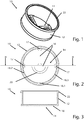
- Fig. 1 shows a housing 10 of a humidity-heat exchanger for tracheotomized and laryngectomized patients.
- the housing 10 has a housing cylinder jacket 12 and a filter retaining device 14.
- filter in particular used from an open-cell foam and used in such a tracheostoma device such as a tracheostoma or a trachial cannula, so that the filter restraint device 14 is proximal to the tracheostomy.
- the filter restraint 14 prevents inadvertent inhalation of the filter.
- the Fig. 1 Furthermore, it can be seen on the outside of the housing cylinder jacket circumferential cover receptacle 22, which is designed as a bead on the distal side.
- Fig. 2 shows the housing 10 in a plan view, wherein the filter restraint device 14 can be seen in detail.
- This has two mutually arranged webs 16, the web ends 17, which are radially outboard, are connected to the inside of the housing cylinder shell 12, or go into this over.
- a stop 20 is arranged, which forms a circular arc in this embodiment.
- the housing cylinder jacket 12 has three indentations 18 which weaken the housing cylinder jacket 12 defined weaken.
- a radial pressure on, for example, the housing cylinder jacket in the region of the notch 18.1 causes the housing cylinder jacket to buckle.
- the defined denting is substantially limited by the notches 18.2 and 18.3 in their scope.
- the denting is limited by the stop 20, so that no unwanted or excessive deformation or uncontrolled fractures happen.
- Fig. 3 shows a sectional view of Fig. 2 in section III-III This view is also the housing cylinder shell 12 and the filter restraint device 14 with the web 16 to remove. Furthermore, it can be seen that the housing 10 has a bead on the distal side, which forms the lid receptacle 22.
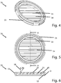
- Fig. 4 shows a cover 30 for the housing 10 of a moisture-heat exchanger.
- the lid 30 has a number of recesses 34 which are bounded by fins 35.
- the Fig. 4 to take a locking element 33, which is provided in particular for receiving a shield.
- Fig. 5 shows the lid 30 from Fig. 4 in a top view. It can be seen that the fins 35 are chamfered and the direct view through the recesses 34 is relatively narrow, although off Fig. 6 it emerges that the recesses are sufficiently large, but run obliquely through the lid.
- the sectional view of the Fig. 5 can be seen through the section VI-VI, pass through the recesses 34 at an angle 36 of about 45 ° to a normal 38 on a cover surface 40 of the lid 30.
- the partially encircling second locking element 33 is the 4 to 6 can be seen that the lid edge 31 rotates on the outside.
- the locking element 33 does not completely surround the lid edge 31, but has interruptions.
- the Fig. 6 it can be seen that the cover 30 comprises a lid edge 31 which has on the inside a circular circumferential first latching element 32. This locking element 32 acts together with the cover receptacle 22 of the housing described above as a first latching connection.
- Fig. 7 to 9 show in a further embodiment of the lid 30, in which the recesses 34 are designed as bores.
- the holes are in the embodiment shown perpendicular to the surface 40 of the lid 30 therethrough.
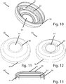
- Fig. 10 shows a shield 50 for attachment to a cover 30.
- the shield 50 has an at least partially encircling inside locking recess 52 which forms a second latching connection with the second locking element 33 of the lid 30.
- the shield 50 also has a breathing opening 54, which is designed in particular such that when placed on or after placement on the cover 30, the recesses are completely exposed. Thus, unhindered breathing is enabled by the assembled humidity-heat exchanger.
- the shield 50 has a housing 10 and the cover 30 embracing edge 56, which ensures in particular that the housing and lid and any structures of the tracheostoma, the tracheostomy or the tracheostoma abutment are not visible. In this way, the aesthetic claim of a user is satisfied, since the assembled moisture-heat exchanger also fulfills a decorative function.
- Fig. 11 shows a variant of the shield 50, wherein the shield 50 has a round in particular approximately circular configuration, in particular in cross section.
- Fig. 12 shows a further embodiment of the shield 50, wherein this has an oval cross-section.
- the breathing opening 54 is oval shaped.
- the breathing opening 54 according to the invention is funnel-shaped. This funnel shape allows, in particular for a deliberate closure by the user, a comfortable position of the finger on the assembled moisture-heat exchanger.
- Fig. 13 shows a sectional view of a shield 50. The section is performed by the interruptions 51 of the groove of the latching receptacle 52, the Fig. 10 can be seen. From this, the breathing opening 54 and the locking receptacle 52 can be seen.
- Fig. 14 shows a kit for a moisture-heat exchanger.
- This has a number of housings 10 and a number of lids 30 and a number of shields 50.
- two variants of the housing 10, the cover 30 and the shields 50 can be seen in each case.
- a user or medical attendant such as a user's physician, may select the appropriate components for the moisture-heat exchanger.
- the housing is designed as a disposable housing. This has individually packaged or directly supplied with a filter 60, which is inserted into the housing.
- the housing including the filter or only the filter is replaced.
- the user may at his discretion choose a lid that prevents on the one hand the direct view of the filter and avoids falling out of the filter in the distal direction.
- the cover has a protective function in that coarser particles, lint or otherwise, and in particular also when the moisture-heat exchanger of the user's fingers is closed, does not come into direct contact with the filter 60.
- the user may also choose from a number of shields 50, which in particular should satisfy an aesthetic requirement.
- the shields also have the technical purpose that a closure of the moisture-heat exchanger, for example, should be comfortable with the finger.
- the shield 50 is made of a rubber-elastic material and on the other hand, the breathing opening 54 is funnel-shaped.
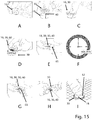
- Fig. 15 shows the use of the described moisture-heat exchanger or its kit.
- Pictogram A shows how a user places the housing 10 on a solid surface. If no filter has been used in the housing 10, the filter 60 is now used and in the following step, as Pictogram B shows, the lid 30 is placed on the housing 10 and locked.
- Pictogram C shows that the locking can easily be done by finger pressure.
- the following icon D shows that the housing 10 provided with the lid 30 is inserted in a shield 50. For this purpose, it is proposed to put the shield 50 on a solid surface and press the housing 10 together with the lid 30 in the shield 50.
- the lid 30 plays a central role. This engages both the housing 10 and the shield 50. According to a preferred embodiment, it is thus not possible to connect the housing 10 without the lid 30 with the shield 50.
- the lid 30 thus has a coupling function.
- Pictogram E shows that the ready assembled moisture-heat exchanger 10, 30 and 50 is inserted into a tracheostoma patch 65.
- Pictogram F should show that the moisture-heat exchanger can be worn for a certain period of time, with a maximum wear time of around 24 hours being recommended. Depending on the degree of soiling or secretion, a previous exchange or, if necessary, a later exchange respectively.
- icon G the moisture-heat exchanger is removed again and the shield 50 is released from the lid 30. Now with slight finger pressure on the housing cylinder jacket 12 in the region of the notches 18, the housing 10, in particular the housing cylinder jacket 12, dented until the lid 30 is released from the housing 10.
- Fig. 16 shows a further embodiment of the lid 30 with three locking elements 32 which are arranged on an inner periphery of the lid edge 31 and formed as latching lugs. To make the structure as compact as possible, the locking elements 32 are close to the edge, that is arranged as proximal as possible on the lid edge. The locking elements 32 protrude about 0.4 mm to about 0.8 mm radially inwards.
- Fig. 17 is a sectional view of the lid 30 from Fig. 16 ,
- Fig. 18 shows a further embodiment of the lid 30 without locking elements. This embodiment allows a clamping of the lid 30 on a housing.
- Fig. 19 is a sectional view of the lid 30 from Fig. 18 ,
Description
Die Erfindung betrifft einen Deckel mit einem Schild zur Befestigung an dem Deckel für ein Gehäuse eines Feuchte-Wärme-Tauschers für Tracheotomierte und Laryngektomierte, sowie einen Bausatz.The invention relates to a lid with a shield for attachment to the cover for a housing of a moisture-heat exchanger for tracheostomized and Laryngektomierte, and a kit.
Feuchte-Wärme-Tauscher für tracheotomierte Patienten sind aus dem Stand der Technik allgemein bekannt. Diese erwärmen und befeuchten die Atemluft mittels eines meist in einer Kassette oder Gehäuse angeordneten Filters. Der Filter speichert die Wärme und Feuchtigkeit der ausgeatmeten Luft und führt diese beim Einatmen der Atemluft wieder zu.Humidity-heat exchangers for tracheotomy patients are well known in the art. These heat and humidify the breathing air by means of a filter usually arranged in a cassette or housing. The filter stores the heat and humidity of the exhaled air and re-introduces it when the breath is inhaled.
Nachteilig an den bekannten Feuchte-Wärme-Tauscher-Gehäusen ist, dass die nur umständlich beziehungsweise aufwendig von eventuellen Aufbauten entfernt werden können. So ist beispielsweise von der Firma Atos Medical die PROVOX HME CAP bekannt, die auf einen Feuchte-Wärme-Tauscher-Filter aufsteckbar ist. Diese soll einen Verschluss des Filters beziehungsweise des Tracheostomas mit dem Finger ermöglichen, so dass ein Sprechen über eine Stimmprothese ermöglicht wird.A disadvantage of the known moisture-heat exchanger housings that the only cumbersome or expensive can be removed from any structures. Thus, for example, from the company Atos Medical the PROVOX HME CAP is known, which is attachable to a moisture-heat exchanger filter. This is to allow a closure of the filter or the tracheostomy with the finger, so that a voice over a voice prosthesis is made possible.
Die genannte Aufsteckkappe umfasst einen gewölbten Titanring der starr ausgeführt ist und ein Atemloch aufweist. Nachteilig an der bekannten Kombination aus Filter beziehungsweise Filterkassette und Kappe ist, dass direkt unterhalb der Kappe der Feuchte-Wärme-Tauscher-Filter angeordnet ist. Dies ist zum einen optisch von Nachteil als auch beim Verschließen des Atemlochs für die Einleitung des Sprechvorganges kommt der Benutzer mit dem Finger in direkte Berührung mit dem Filter, was zur Verunreinigung führen kann. Ein weiterer Nachteil der bekannten Feuchte-Wärme-Tauscher ist, dass das Gehäuse nur sehr umständlich von den Aufbauten zu entfernen ist und es somit bei älteren Personen zu Problemen bei der Nutzung kommen kann.Said Aufsteckkappe includes a curved titanium ring which is rigid and has a breathing hole. A disadvantage of the known combination of filter or filter cartridge and cap is that directly below the cap of the moisture-heat exchanger filter is arranged. This is on the one hand visually disadvantageous as well as when closing the breathing hole for the initiation of the speech process, the user comes with the finger in direct contact with the filter, which can lead to contamination. Another disadvantage of the known humidity-heat exchanger is that the housing is very cumbersome to remove from the structures and thus it may cause problems in use for the elderly.
Aus dem Stand der Technik sind auch die folgenden Feuchte-Wärme-Tauscher bekannt,
Aufgabe der Erfindung ist es daher, die bekannten Nachteile aus dem Stand der Technik zu überkommen und einen verbesserten Feuchte-Wärme-Tauscher für Tracheotomierte und Laryngektomierte zur Verfügung zu stellen.The object of the invention is therefore to overcome the known disadvantages of the prior art and to provide an improved moisture-heat exchanger for Tracheotomierte and Laryngektomierte available.
Die Aufgabe wird, nach Anspruch 1, gelöst mittels eines Deckels mit einem Schild zur Befestigung an dem Deckel für ein Gehäuse eines Feuchte-Wärme-Tauschers für Laryngektomierte und Tracheotomierte umfassend eine als weitgehend kreisrunde Scheibe ausgebildete Deckelplatte, einen Deckelrand und eine Anzahl von den Deckel durchgreifende Ausnehmungen zumindest ein teilweise kreisrund umlaufendes erstes Rastelement angeordnet ist, wobei der Deckelrand außenseitig zumindest ein teilweise umlaufendes zweites Rastelement umfasst, wobei der Schild eine Atemöffnung aufweist, wobei der Schild um die Atemöffnung eine trichterförmige Ausgestaltung aufweist, um einen Finger auf das Atemloch bei einem gewollten Verschluss desselben zu führen, wobei der Schild eine zumindest teilweise umlaufende innenseitige Rastaufnahme für das zweite Rastelement des Deckels umfasst. Weiterhin wird die Aufgabe erfindungsgemäß gelöst mittels eines Bausatzes umfassend zumindest eine Anzahl von Gehäusen eine Rastaufnahme zur Aufnahme eines ersten Rastelements eines Deckels aufweisen, eine Anzahl von Deckeln und eine Anzahl von Schilden. Weitere vorteilhafte Ausgestaltungen sind der nachfolgenden Beschreibung, den Figuren sowie den Unteransprüchen zu entnehmen. Die einzelnen Merkmale der verschiedenen Ausgestaltungen sind jedoch nicht auf diese beschränkt sondern können untereinander und mit anderen Merkmalen zur weiteren Ausgestaltung verknüpft werden.The object is, according to claim 1, achieved by means of a lid with a shield for attachment to the cover for a housing of a moisture-heat exchanger for Laryngektomierte and Tracheotomierte comprising a designed as a largely circular disc cover plate, a lid edge and a number of the lid at least a partially circular encircling first latching element is arranged, wherein the lid edge on the outside at least a partially encircling second latching element, wherein the shield has a breathing opening, wherein the shield around the breathing opening has a funnel-shaped configuration to a finger on the breathing hole in a intended to lead closure of the same, wherein the shield comprises an at least partially encircling inner side locking receptacle for the second locking element of the lid. Furthermore, the object is achieved by means of a kit comprising at least a number of housings having a locking receptacle for receiving a first locking element of a lid, a number of lids and a number of shields. Further advantageous embodiments are given in the following description, the figures and the dependent claims. However, the individual features of the various embodiments are not limited to these but can be linked with each other and with other features for further refinement.
Es wird ein Deckel mit einem Schild zur Befestigung an dem Deckel für ein Gehäuse eines Feuchte-Wärme-Tauschers für Tracheotomierte und Laryngektomierte vorgeschlagen, der eine als weitgehend kreisrunde Scheibe ausgebildete Deckelplatte, einen Deckelrand und eine Anzahl von den Deckel durchgreifenden Ausnehmungen umfasst, wobei die Deckelplatte zwei oder mehr Ausnehmungen aufweist, wobei innenseitig am Deckelrand zumindest ein teilweise kreisrund umlaufendes erstes Rastelement angeordnet ist, wobei der Deckelrand außenseitig zumindest ein teilweise umlaufendes zweites Rastelement umfasst, wobei der Schild eine Atemöffnung aufweist, wobei der Schild um die Atemöffnung eine trichterförmige Ausgestaltung aufweist, um einen Finger auf das Atemloch bei einem gewollten Verschluss desselben zu führen, wobei der Schild eine zumindest teilweise umlaufende innenseitige Rastaufnahme für das zweite Rastelement des Deckels umfasst.It is proposed a lid with a shield for attachment to the cover for a housing of a moisture-heat exchanger for Tracheotomierte and Laryngektomierte comprising a designed as a largely circular disc cover plate, a lid edge and a number of the lid cross recesses, wherein the Cover plate has two or more recesses, wherein on the inside of the cover edge at least a partially circular circulating first latching element is arranged, wherein the cover edge on the outside comprises at least a partially encircling second latching element, wherein the shield has a breathing opening, wherein the shield around the breathing opening has a funnel-shaped configuration to guide a finger on the breathing hole at a desired closure thereof, wherein the shield comprises an at least partially encircling inside locking recess for the second locking element of the lid.
Vorteilhafterweise ist in einer Ausgestaltung vorgesehen, dass der Deckel auf einem weiteren Bauteil eines Feucht-Wärme-Tauschers, insbesondere einem Gehäuse, klemmbar befestigbar ist. Weiterhin ist bevorzugt vorgesehen, dass der Deckel aufschraubbar oder aufrastbar ist. In einer vorteilhaften Ausgestaltung ist vorgesehen, dass der Deckel Klemmelemente aufweist. Vorteil an der Ausgestaltung ist, dass ein sicherer Sitz insbesondere auf dem Gehäuse gewährleistet ist und gleichzeitig die Herstellung des Feucht-Wärmetauschers insbesondere in Hinblick auf die Werkzeugkosten vereinfacht wird.Advantageously, it is provided in one embodiment that the lid can be clamped on a further component of a moist heat exchanger, in particular a housing. Furthermore, it is preferably provided that the lid can be screwed or latched. In an advantageous embodiment, it is provided that the lid has clamping elements. An advantage of the embodiment is that a secure fit is ensured in particular on the housing and at the same time the production of the wet heat exchanger is simplified, in particular with regard to the tooling costs.
In einer Ausführungsform ist vorgesehen, dass innenseitig am Deckelrand zumindest ein Rastelement angeordnet ist.In one embodiment, it is provided that at least one latching element is arranged on the inside of the lid edge.
Erfindungsgemäß ist vorgesehen, dass innenseitig am Deckelrand zumindest ein teilweise kreisrund umlaufendes erstes Rastelement angeordnet ist. Gemäß einer Ausführungsform ist das Rastelement als Nut ausgestaltet. Vorzugsweise weist das Gehäuse zumindest ein vorzugsweise ebenfalls kreisrund umlaufend ausgestaltetes Rastelement beziehungsweise eine kreisrund ausgestaltete Deckelaufnahme auf, die mit zumindest dem ersten Rastelement des Deckels zusammenwirkt. Dies hat den Vorteil, dass der Deckel drehbar auf dem Gehäuse angeordnet ist. In einer weiteren Ausgestaltung sind das zumindest eine Rastelement des Gehäuses und das zumindest eine Rastelement des Deckels derart ausgestaltet, dass diese drehhemmend miteinander verrastbar sind. Vorzugsweise ist eine Drehhemmung mittels Kraftschluss vorgesehen.According to the invention, provision is made for at least one, partially circular, circumferential first latching element to be arranged on the inside of the lid. According to one embodiment, the latching element is designed as a groove. Preferably, the housing has at least one latching element or else preferably likewise circularly configured a circular configured lid receptacle, which cooperates with at least the first latching element of the lid. This has the advantage that the cover is rotatably mounted on the housing. In a further embodiment, the at least one latching element of the housing and the at least one latching element of the cover are configured such that they can be latched to one another in a rotationally inhibiting manner. Preferably, a rotational inhibition is provided by means of adhesion.
In einer weiteren Ausführungsform ist vorgesehen, dass innenseitig am Deckelrand eine Anzahl von Rastelementen angeordnet sind. Vorzugsweise sind die Rastelemente als Rastnasen oder Rastvorsprünge ausgestaltet. In einer bevorzugten Ausgestaltung ist vorgesehen, dass die Rastelemente sich etwa 0,1 mm bis etwa 0,9 mm, bevorzugt etwa 0,4 mm bis etwa 0,8 mm radial nach innen über den Deckelrand erheben. Diese Ausgestaltung erlaubt eine besonders kompakte Bauweise.In a further embodiment it is provided that a number of latching elements are arranged on the inside of the lid edge. Preferably, the locking elements are designed as latching lugs or latching projections. In a preferred embodiment, it is provided that the latching elements rise about 0.1 mm to about 0.9 mm, preferably about 0.4 mm to about 0.8 mm radially inwardly over the edge of the lid. This embodiment allows a particularly compact design.
In einer weiteren Ausgestaltung ist vorgesehen, dass die Rastelemente am Innenumfang des Deckelrandes umlaufend verteilt sind. Vorzugsweise sind etwa 3 bis etwa 20 Rastelemente, weiter bevorzugt etwa 6 bis etwa 15 Rastelemente, weiter bevorzugt 6 oder 8 oder 9 Rastelemente vorgesehen.In a further embodiment, it is provided that the latching elements are circumferentially distributed on the inner circumference of the lid edge. Preferably, about 3 to about 20 locking elements, more preferably about 6 to about 15 locking elements, more preferably 6 or 8 or 9 locking elements are provided.
Der Deckel umfasst eine Deckeloberfläche beziehungsweise eine Deckelplatte, die erfindungsgemäß eine weitgehend kreisrunde Scheibe bildet. Weiterhin weist der Deckel einen Deckelrand auf, der besonders bevorzugt sich von der Deckelplatte weg erstreckt. Auf diese Weise wird ein Zylindermantel unterhalb der Platte das heißt beim Gebrauch des Deckels in Richtung des Gehäuses erstreckender Deckelrand gebildet. Vorzugsweise umfasst der Deckelrand auch die radiale Oberfläche der Deckelplatte.The cover comprises a cover surface or a cover plate, which according to the invention forms a largely circular disk. Furthermore, the cover has a lid edge, which particularly preferably extends away from the cover plate. In this way, a cylinder jacket below the plate that is formed during use of the lid in the direction of the housing extending lid edge. Preferably, the lid edge also includes the radial surface of the cover plate.
Das erste Rastelement ist gemäß einer Ausgestaltung als Wulst, Rastnase oder Vorsprung ausgeführt. Das erste Rastelement kann dabei als ein zusammenhängender kreisrunder Wulst auf der Innenseite des Deckelrandes ausgeführt sein. In einer weiteren Ausgestaltung ist vorgesehen, dass das erste Rastelement eine Anzahl von Wulsten oder Vorsprüngen aufweist, die innenseitig am Deckelrand angeordnet sind.The first latching element is designed according to an embodiment as a bead, latching lug or projection. The first locking element can be designed as a continuous circular bead on the inside of the lid edge. In a further embodiment It is provided that the first latching element has a number of beads or projections which are arranged on the inside of the lid edge.
Der Deckel weist eine Anzahl von den Deckel durchgreifenden Ausnehmungen auf, die dem Benutzer ermöglichen, ausreichend Luft ein- und auszuatmen und insbesondere durch einen unter dem Deckel angeordneten Filter zu leiten. Erfindungsgemäß weist die Deckelplatte zwei oder mehr Ausnehmungen auf. Besonders bevorzugt ist vorgesehen, dass etwa 30 % bis etwa 90 % der Deckeloberfläche mit Ausnehmungen durchsetzt sind.The lid has a number of recesses extending through the lid, which allow the user to inhale and exhale sufficient air and in particular to guide it through a filter arranged under the lid. According to the invention, the cover plate has two or more recesses. It is particularly preferred that about 30% to about 90% of the lid surface are interspersed with recesses.
Besonders bevorzugt ist eine Ausgestaltung vorgesehen, bei der Ausnehmungen in einem Winkel von etwa 30° bis etwa 60°, bevorzugt etwa 45°, zu einer Normalen auf einer Deckeloberfläche den Deckel durchgreifen. Die Ausnehmungen oder Löcher gehen somit schräg beziehungsweise diagonal durch den Deckel. Dies hat den Vorteil, dass ein direkter Durchgriff beziehungsweise ein Sichtbarwerden des unter dem Deckel liegenden Filters oder anderer Vorrichtungen durch die Ausnehmungen vermieden werden kann. Dennoch ist es dem Benutzer möglich, gut und sicher durch den Deckel zu atmen. Ein weiterer Vorteil an der beschriebenen Ausführungsform ist, dass ein für den Benutzer ansprechendes Design erreicht werden kann. Ein weiterer Vorteil der schräg oder diagonal durch den Deckel ausgeführten Ausnehmungen oder Bohrungen ist, dass, insbesondere wenn Personen sich dem Benutzer nähern, ein Anblasen Dritter vermieden wird. Die Luft kann durch diese Ausgestaltung vorteilhaft nach unten oder zur Seite abgelenkt werden. Auch kann Spritzwasser mit dieser Konstruktion zuverlässig abgeschirmt werden.Particularly preferred embodiment is provided, in which recesses at an angle of about 30 ° to about 60 °, preferably about 45 °, pass through the lid to a normal on a lid surface. The recesses or holes thus go obliquely or diagonally through the lid. This has the advantage that direct penetration or visibility of the filter or other devices under the cover can be avoided by the recesses. Nevertheless, it is possible for the user to breathe well and safely through the lid. Another advantage of the described embodiment is that a user-friendly design can be achieved. Another advantage of the recesses or bores made obliquely or diagonally through the cover is that, especially when persons approach the user, third-party blowing is avoided. The air can be deflected by this configuration advantageous down or to the side. Also spray water can be reliably shielded with this construction.
In einer weiteren Ausführungsform ist vorgesehen, dass zumindest ein Teil der Ausnehmungen Bohrungen sind. Im Sinne der Erfindung sind unter Bohrungen runde, kreisrunde, aber auch ovale Ausnehmungen zu verstehen, die vollständig durch den Deckel hindurchgehen beziehungsweise diesen durchgreifen. Die Bohrungen können orthogonal zur Deckeloberfläche oder in einem Winkel von etwa 30° bis etwa 60°, bevorzugt etwa 45°, zu einer Normalen auf der Deckeloberfläche den Deckel durchgreifen. In einer weiteren Ausgestaltung ist vorgesehen, dass die Ausnehmungen gitterförmig auf der Deckeloberfläche angeordnet sind. Insbesondere sind Bohrungen oder sonst wie gestaltete Ausnehmungen gitterförmig vorgesehen. Eine weitere Ausgestaltung sieht vor, dass die Ausnehmungen einen über ihre Länge veränderlichen Querschnitt beziehungsweise eine veränderliche Öffnungsweite aufweisen. Insbesondere weiten sich die Ausnehmungen in distaler oder proximaler Richtung auf. Besonders bevorzugt ist ebenfalls, dass zumindest ein Teil der Ausnehmungen Schlitze sind. In einer weiteren Ausgestaltung ist vorgesehen, dass alle Ausnehmungen als Schlitze ausgestaltet sind. Weiterhin vorteilhaft sind die Schlitze, wie oben erwähnt, beispielsweise diagonal oder schräg und/oder mit sich veränderlichem Querschnitt vorgesehen.In a further embodiment it is provided that at least a part of the recesses are bores. For the purposes of the invention are round holes round, circular, but also oval recesses to understand that pass completely through the lid or reach through this. The holes can pass through the lid orthogonally to the lid surface or at an angle of about 30 ° to about 60 °, preferably about 45 °, to a normal on the lid surface. In a further embodiment, it is provided that the recesses are arranged in a lattice-like manner on the cover surface are. In particular, holes or otherwise designed recesses are provided in a grid shape. A further embodiment provides that the recesses have a variable over their length cross-section or a variable opening width. In particular, the recesses widen in the distal or proximal direction. It is also particularly preferred that at least a part of the recesses are slots. In a further embodiment, it is provided that all recesses are configured as slots. Further advantageously, the slots, as mentioned above, for example, diagonally or obliquely and / or provided with variable cross-section.
Gemäß einer weiteren Ausgestaltung ist vorgesehen, dass Lamellen zwischen den Ausnehmungen angeordnet sind. Die Ausnehmungen sind vorteilhafterweise als Schlitze ausgestaltet. Die Schlitze erstrecken sich gemäß einer Ausgestaltung über eine gesamte Breite des Deckels. Weiter bevorzugt sind die Schlitze parallel zueinander angeordnet. Die Lamellen können in einer weiteren Ausgestaltung durch die Vorsehung der Schlitze gebildet sein.According to a further embodiment, it is provided that lamellae are arranged between the recesses. The recesses are advantageously designed as slots. The slots extend according to an embodiment over an entire width of the lid. More preferably, the slots are arranged parallel to each other. The slats can be formed in a further embodiment by the provision of the slots.
Erfindungsgemäß ist vorgesehen, dass der Deckelrand außenseitig zumindest ein teilweise umlaufendes zweites Rastelement umfasst. Das zweite Rastelement ist insbesondere ausgestaltet als vollständig oder teilweise umlaufende Wulst, Vorsprung oder anderweitige Ausprägung. Weiterhin vorteilhaft sind mehrere Ausprägungen vorgesehen, die zusammen das Rastelement bilden. Das zweite Rastelement auf der Außenseite des Deckelrandes ist insbesondere dafür vorgesehen, einen Schild aufzunehmen, insbesondere einen Schild, welcher einen Verschluss des Deckels beziehungsweise des Atemdurchgangs vereinfacht.According to the invention, it is provided that the lid edge on the outside comprises at least one partially circumferential second latching element. The second latching element is designed in particular as a completely or partially encircling bead, projection or other form. Further advantageous several features are provided, which together form the locking element. The second detent element on the outside of the lid edge is in particular intended to receive a shield, in particular a shield, which simplifies a closure of the lid or of the breathing passage.
Insbesondere ist in einer Ausgestaltung vorgesehen, dass das mindestens eine zweite Rastelement am Deckel vorgesehen ist, ohne dass das mindestens eine erste Rastelement am Deckel vorgesehen ist. In einer weiteren Ausführungsform ist vorgesehen, dass das mindestens eine erste Rastelement ohne ein zweites oder weiteres Rastelement vorgesehen ist. In einer weiteren Ausführungsform ist vorgesehen, dass das mindestens eine erste Rastelement und das mindestens eine zweite Rastelement vorgesehen sind. Weiterhin sieht eine Ausführungsform vor, dass das mindestens eine erste Rastelement und/oder das mindestens eine zweite Rastelement und zumindest ein weiteres Rastelement vorgesehen sind. Das mindestens eine erste Rastelement und/oder das mindestens eine zweite Rastelement können somit unabhängig voneinander und je nach Anforderung durch die vorgesehenen, mit dem Deckel in Verbindung gebrachten Bauteile am Deckel angeordnet sein.In particular, it is provided in one embodiment that the at least one second detent element is provided on the lid, without the at least one first detent element being provided on the lid. In a further embodiment it is provided that the at least one first latching element is provided without a second or further latching element. In a further embodiment it is provided that the at least one first latching element and the at least one second latching element are provided. Furthermore, an embodiment sees in that the at least one first latching element and / or the at least one second latching element and at least one further latching element are provided. The at least one first latching element and / or the at least one second latching element can thus be arranged on the cover independently of one another and as required by the intended components brought into contact with the cover.
In einer weiteren Ausführungsform ist vorgesehen, dass der Schild auf das Deckel aufklemmbar ist. Insbesondere ist gemäß einer Ausgestaltung vorgesehen, dass der Schild kein Rastelement aufweist. Weiterhin ist gemäß einer Ausführungsform vorgesehen, dass der Schild mindestens einen zumindest teilweise umlaufenden Wulst insbesondere zur Klemmung auf dem Deckel umfasst. Weiterhin sieht eine Variante des Schildes vor, dass dieser mit dem Deckel mittels einer kraftschlüssigen und/oder formschlüssigen Verbindung verbindbar ist.In a further embodiment it is provided that the shield can be clamped onto the lid. In particular, it is provided according to an embodiment that the shield has no latching element. Furthermore, it is provided according to an embodiment that the shield comprises at least one at least partially circumferential bead in particular for clamping on the lid. Furthermore, a variant of the shield provides that this is connectable to the lid by means of a non-positive and / or positive connection.
Weiterhin wird ein Gehäuse zur Befestigung an dem oben beschriebenen Deckel vorgeschlagen, wobei das Gehäuse eine Rastaufnahme zur Aufnahme eines ersten Rastelementes des Deckels aufweist.Furthermore, a housing for attachment to the lid described above is proposed, wherein the housing has a latching receptacle for receiving a first latching element of the lid.
Gemäß einer Ausgestaltung ist vorgesehen, dass der Deckel auf dem Gehäuse aufklemmbar ist.According to one embodiment, it is provided that the cover can be clamped onto the housing.
Vorteilhafterweise ist vorgesehen, dass der Deckel mittels der beschriebenen ersten Rastverbindung, die insbesondere aus dem ersten Rastelement des Deckels und der Rastaufnahme des Gehäuses besteht, oder diese Einzelteile zumindest umfasst, auf dem Gehäuse befestigbar ist. Wie bereits erwähnt, ist vorteilhafterweise vorgesehen, dass die erste Rastverbindung derart ausgestaltet ist, dass der Deckel drehbar auf dem Gehäuse angeordnet ist. Weiterhin ist durch diese Ausgestaltung eine kompakte Bauweise erreicht.Advantageously, it is provided that the cover by means of the first latching connection described, which consists in particular of the first latching element of the lid and the latching receptacle of the housing, or at least comprises these items, can be fastened on the housing. As already mentioned, it is advantageously provided that the first latching connection is designed such that the cover is rotatably arranged on the housing. Furthermore, a compact design is achieved by this configuration.
Weiterhin wird ein Schild zur Befestigung an dem Deckel vorgeschlagen, wobei der Schild eine zumindest teilweise umlaufende innenseitige Rastaufnahme für ein zweites Rastelement des Deckels umfasst. Der Deckel ist vorzugsweise mittels einer zweiten Rastverbindung, die zumindest das zweite Rastelement des Deckels und die Rastaufnahme des Schildes umfasst, an dem Schild befestigbar. Der Schild ist vorzugsweise derart ausgestaltet, dass dieser eine Atemöffnung aufweist, die im Wesentlichen so groß ist wie der Durchmesser des Deckels. In einer weiteren Ausgestaltung ist vorgesehen, dass das Atemloch des Schildes etwa 1 % bis etwa 5 % kleiner ist als der Durchmesser des Deckels. Besonders bevorzugt ist vorgesehen, dass das Atemloch zentrisch über dem Deckel anordbar ist. Weiterhin bevorzugt ist in einer Ausgestaltung vorgesehen, dass der Schild um das Atemloch herum eine Einbuchtung beziehungsweise eine trichterförmige Ausgestaltung aufweist. Die trichterförmige Ausgestaltung kann sowohl kreisrund als auch oval ausgestaltet sein, um insbesondere das Auflegen eines Fingers zu erleichtern. Die erfindungsgemäße trichterförmige Ausgestaltung ist vorteilhaft, weil dadurch der Finger auf das Atemloch geführt wird bei einem gewollten Verschluss desselben. Der Benutzer legt den Finger auf das Atemloch, um die ausgeatmete Luft durch eine Stimmprothese zu leiten. Durch die vorgeschlagene Ausgestaltung ist eine leichtere Abdichtung, insbesondere durch geringeren Druck auf den Schild beziehungsweise den Feuchte-Wärme-Tauscher, notwendig um einen dichtenden Verschluss zu erzielen.Furthermore, a shield for attachment to the lid is proposed, wherein the shield comprises an at least partially encircling inside locking recess for a second locking element of the lid. The cover is preferably by means of a second latching connection, the at least the second locking element of the lid and the locking receptacle of the shield comprises, attachable to the shield. The shield is preferably configured such that it has a breathing opening which is substantially as large as the diameter of the lid. In a further embodiment, it is provided that the breathing hole of the shield is about 1% to about 5% smaller than the diameter of the lid. Particularly preferably, it is provided that the breathing hole can be arranged centrally above the lid. Furthermore, it is preferably provided in one embodiment that the shield around the breathing hole has a recess or a funnel-shaped configuration. The funnel-shaped configuration can be designed both circular and oval, in particular to facilitate the placement of a finger. The funnel-shaped embodiment according to the invention is advantageous because the finger is thereby guided on the breathing hole at a desired closure of the same. The user places his finger on the breathing hole to direct the exhaled air through a voice prosthesis. The proposed embodiment is a lighter seal, in particular by lower pressure on the shield or the moisture-heat exchanger, necessary to achieve a sealing closure.
In einer besonders bevorzugten Ausgestaltung ist vorgesehen, dass der Schild und/oder der Deckel aus einem gummielastischen Kunststoff oder einem elastischen Material hergestellt ist. Beispielsweise ist vorgesehen, dass der Schild und/oder der Deckel eine Material umfasst, ausgewählt aus einer Gruppe zumindest umfassend ein Metall, Polypropylen und/oder Polyvinylchlorid. In einer Ausgestaltung ist vorgesehen, dass der Schild mittels eines generativen Fertigungsverfahren , beispielsweise mittels eines 3D-Druckers hergestellt ist.In a particularly preferred embodiment, it is provided that the shield and / or the lid is made of a rubber-elastic plastic or an elastic material. For example, it is provided that the shield and / or the cover comprises a material selected from a group comprising at least one metal, polypropylene and / or polyvinyl chloride. In one embodiment, it is provided that the shield is produced by means of a generative manufacturing method, for example by means of a 3D printer.
Gemäß einer Ausgestaltung ist vorgesehen, dass die Rastaufnahme des Schilds mindestens eine Nut aufweist, die vorzugsweise zumindest teilweise, bevorzugt vollständig kreisrund umlaufend ausgestaltet ist. Insbesondere ist die zumindest eine Nut in einem Längsschnitt, das heißt einem Schnitt von proximal nach lateral, C-förmig oder L-förmig ausgebildet. Weiter bevorzugt ist vorgesehen, dass die Nut einmal oder mehrfach unterbrochen ist, das heißt, dass die Rastaufnahme eine Anzahl von Nuten aufweist, die nebeneinander angeordnet sind, oder eine Nut aufweist, die nicht vollständig oder vollständig umlaufend ausgestaltet ist. Vorteilhafterweise ist gemäß einer Ausgestaltung vorgesehen, dass das zweite Rastelement des Deckels korrespondierend zu der Rastaufnahme, insbesondere der Nut, des Schilds ausgestaltet ist. Das heißt, dass das zweite Rastelement die gleiche Anzahl von Ausprägungen aufweist, die in die Nut oder Nute eingreifen können, wie Nute in der Rastaufnahme vorgesehen sind. Weiterhin bevorzugt ist vorgesehen, dass die Nute der Rastaufnahme und die Ausprägungen des zweiten Rastelements aufeinander abgestimmt sind, insbesondere im Wesentlichen passgenau ausgestaltet sind. Vorteil an der beschriebenen Ausgestaltung mit einer unterbrochenen Nut ist, dass der Schild verdrehsicher auf dem Deckel aufsitzt.According to one embodiment, it is provided that the latching receptacle of the shield has at least one groove, which is preferably at least partially, preferably designed to be completely circular in circumference. In particular, the at least one groove is formed in a longitudinal section, that is, a section from proximal to lateral, C-shaped or L-shaped. Continue Preferably, it is provided that the groove is interrupted once or several times, that is, that the locking receptacle has a number of grooves which are arranged side by side, or has a groove which is not designed completely or completely circulating. Advantageously, it is provided according to an embodiment that the second latching element of the lid is configured corresponding to the latching receptacle, in particular the groove, of the shield. This means that the second latching element has the same number of characteristics that can engage in the groove or groove, as grooves are provided in the latching receptacle. Further preferably, it is provided that the groove of the latching receptacle and the characteristics of the second latching element are matched to one another, in particular are configured substantially accurately. Advantage of the described embodiment with an interrupted groove that the shield is seated against rotation on the cover.
Ein weiterer Aspekt des vorgeschlagenen Feuchte-Wärme-Tauschers ist ein Bausatz umfassend zumindest eine Anzahl von Gehäusen, wobei die Gehäuse eine Rastaufnahme zur Aufnahme eines ersten Rastelements eines Deckels aufweisen, wie oben beschrieben, eine Anzahl von Deckeln, wie oben beschrieben, und eine Anzahl von Schilden, wie oben beschrieben. Vorzugsweise ist der Bausatz für einen Feuchte-Wärme-Tauscher mit unterschiedlichen Gehäusen und/oder unterschiedlichen Deckeln und/oder unterschiedlichen Schilden ausgestattet. Der Vorteil an dem vorgeschlagenen Bausatz ist, dass die medizinische Versorgung, beziehungsweise die Versorgung mit einem Feuchte-Wärme-Tauscher an den Benutzer individuell angepasst werden kann. Der Bausatz zeichnet sich insbesondere dadurch aus, dass in einer Ausgestaltung vorgesehen ist, dass die Gehäuse Einwegartikel sind. Das hat den Vorteil, dass nicht der komplette Feuchte-Wärme-Tauscher ausgewechselt beziehungsweise weggeschmissen werden muss, sondern einzelne Teile nach Reinigung wieder verwendet werden können und nur das Gehäuse, in einer weiteren Ausgestaltung nur der Filter, der im Gehäuse angeordnet ist, ausgetauscht wird. In einer weiteren Ausgestaltung ist vorgesehen, dass alle Teile des Bausatzes mehrfach verwendet werden können. In einer weiteren Variante ist vorgesehen, dass die Schilde eine Anzahl von unterschiedlichen Farben oder Außenformen aufweisen. Beispielsweise können die Außenformen bei einer Draufsicht im Wesentlichen rund oder im Wesentlichen oval ausgestaltet sein. Auch sind unterschiedliche Materialien oder Materialkombinationen für die Schilde in weiteren Ausgestaltungen vorgesehen. So sind beispielsweise unterschiedliche Elastizitäten für die verschiedenen Zwecke beziehungsweise Bedürfnisse des Benutzers vorgesehen. In einer weiteren Ausführungsform ist vorgesehen, dass die Schilde unterschiedliche Atemöffnungen und/oder Trichterformen aufweisen.Another aspect of the proposed humidity-heat exchanger is a kit comprising at least a number of housings, the housings having a detent receptacle for receiving a first detent element of a cover as described above, a number of covers as described above, and a number of shields, as described above. The kit for a moisture-heat exchanger is preferably equipped with different housings and / or different covers and / or different shields. The advantage of the proposed kit is that the medical care, or the supply of a moisture-heat exchanger to the user can be customized. The kit is characterized in particular by the fact that in one embodiment it is provided that the housings are disposable items. This has the advantage that not the entire moisture-heat exchanger must be replaced or discarded, but individual parts can be reused after cleaning and only the housing, in a further embodiment, only the filter, which is arranged in the housing, is replaced , In a further embodiment, it is provided that all parts of the kit can be used multiple times. In a further variant, it is provided that the shields have a number of different colors or outer shapes. For example, the outer shapes in a plan view substantially be designed round or substantially oval. Also are different materials or material combinations for the shields provided in further embodiments. For example, different elasticities are provided for the different purposes or needs of the user. In a further embodiment it is provided that the shields have different breathing openings and / or funnel shapes.
Der Bausatz ist in einer Ausgestaltung derart ausgeführt, dass die Deckel eine Anzahl von unterschiedlich ausgestalteten Ausnehmungen aufweisen. So sind Ausnehmungen vorgesehen, die im Querschnitt rund oder oval sind. Weitere Ausgestaltungen sehen vor, dass eine weitere Anzahl von Ausnehmungen gerade durchlaufen und/oder diagonal oder schräg den Deckel durchgreifen.The kit is designed in one embodiment such that the lid has a number of differently configured recesses. Thus, recesses are provided which are round or oval in cross-section. Further embodiments provide that a further number of recesses pass straight through and / or pass diagonally or obliquely through the lid.
In einer weiteren Ausgestaltung ist vorgesehen, dass die Deckel unterschiedliche Farben aufweisen. Der Bausatz hat den weiteren Vorteil, dass nicht nur medizinisch angepasste Leistungen auf den Benutzer zugeschnitten werden können sondern auch, dass das Design entsprechend dem Geschmack der Benutzer ausgestaltet sein kann.In a further embodiment, it is provided that the lids have different colors. The kit has the further advantage that not only medically adapted services can be tailored to the user but also that the design can be designed according to the taste of the user.
In einer weiteren Ausgestaltung ist vorgesehen, dass die Deckel auf den Gehäusen aufklemmbar sind.In a further embodiment it is provided that the cover can be clamped on the housings.
In einer weiteren Ausführungsform ist vorgesehen, dass die Deckel mittels einer ersten Rastverbindung auf dem Gehäuse befestigbar sind.In a further embodiment it is provided that the cover can be fastened on the housing by means of a first latching connection.
In einer weiteren Variante ist vorgesehen, dass die Deckel drehbar auf dem Gehäuse sind.In a further variant, it is provided that the lids are rotatable on the housing.
Weiterhin wird ein Gehäuse eines Feuchte-Wärme-Tauschers für Tracheotomierte und Laryngektomierte umfassend einen Gehäusezylindermantel vorgeschlagen. Das Gehäuse weist weiterhin eine Filterrückhaltevorrichtung auf, wobei die Filterrückhaltevorrichtung zumindest einen Steg umfasst, der einer Grundfläche des Gehäuses zugeordnet ist. Der Gehäuse zylindermantel weist zumindest drei Einkerbungen, die insbesondere als Filmscharnier ausgestaltet sind, auf, die ein definiertes Einbeulen des Gehäusezylindermantels ermöglichen.Furthermore, a housing of a moisture-heat exchanger for Tracheotomierte and Laryngektomierte comprising a housing cylinder jacket is proposed. The housing further has a filter retaining device, wherein the filter retaining device comprises at least one web, which is associated with a base surface of the housing. The case Cylinder jacket has at least three indentations, which are designed in particular as a film hinge, on which allow a defined denting of the housing cylinder jacket.
Vorteilhafterweise kann das Gehäuse in oder auf ein Tracheostomapflaster, ein Tracheostomabutton und/oder eine Tracheostomakanüle eingesetzt werden. Das Gehäuse ist bevorzugt zylindrisch ausgestaltet, wobei eine Grundfläche des Gehäuses durch die Filterrückhaltevorrichtung gebildet wird. Die Filterrückhaltevorrichtung weist einen oder mehrere Stege auf, insbesondere ist vorgesehen, dass die Stege miteinander im Verbund stehen. Der Gehäusezylindermantel weist weiterhin zumindest drei Einkerbungen auf, die in einer bevorzugten Ausgestaltung Filmscharniere sind. In einer weiteren Ausgestaltung ist vorgesehen, dass die Einkerbungen als Sollbruchstellen ausgestaltet sind. Die Einkerbungen sind vorzugsweise derart über den Gehäusezylindermantel verteilt, dass durch Druck, insbesondere Fingerdruck auf den Gehäusezylindermantel dieser eingebeult wird. Unter einer Einbeulung ist im Sinne der Erfindung zu verstehen, dass die durch die Einkerbungen definierten Sektionen des Gehäusezylindermantels zueinander bewegt und insbesondere radial eingedrückt werden.Advantageously, the housing can be inserted into or onto a tracheostoma plaster, a tracheostoma abutton and / or a tracheostoma cannula. The housing is preferably designed cylindrical, wherein a base surface of the housing is formed by the filter retaining device. The filter restraint device has one or more webs, in particular it is provided that the webs are interconnected. The housing cylinder shell further has at least three notches, which in a preferred Design film hinges are. In a further embodiment, it is provided that the notches are designed as predetermined breaking points. The notches are preferably distributed over the housing cylinder jacket, that is dented by pressure, in particular finger pressure on the housing cylinder jacket. In the context of the invention, a denting is to be understood as meaning that the sections of the housing cylinder jacket defined by the indentations are moved relative to one another and, in particular, are pressed radially.
Der Vorteil an dem beschriebenen Gehäuse ist, dass, sofern ein Deckel oder ein weiteres Bauteil auf dem Gehäuse angeordnet ist, dieses leicht aus der Rastverbindung gelöst werden kann, indem ein Druck, insbesondere Fingerdruck radial auf den Gehäusezylindermantel ausgeübt wird. Sodann beult sich der Gehäusezylindermantel definiert ein, so dass dieser aus einer Rastverbindung mit einem weiteren Bauteil, insbesondere einem Deckel, gelöst wird.The advantage of the housing described is that, if a cover or another component is arranged on the housing, this can be easily released from the latching connection by a pressure, in particular finger pressure is exerted radially on the housing cylinder jacket. Then, the housing cylinder jacket bulges defined, so that it is released from a latching connection with another component, in particular a lid.
In einer bevorzugten Ausgestaltung ist vorgesehen, dass die Einkerbungen in einem Winkel von etwa 15° bis etwa 75°, weiter bevorzugt etwa 50° bis etwa 70°, weiter bevorzugt etwa 60° zueinander angeordnet sind. Die Anordnung der Kerben und insbesondere auch die Anzahl der Kerben bestimmen den Grad der Einbeulung und den Widerstand, den der Gehäusezylindermantel bei Druck auf selbigen ausübt.In a preferred embodiment, it is provided that the notches are arranged at an angle of about 15 ° to about 75 °, more preferably about 50 ° to about 70 °, more preferably about 60 ° to each other. The arrangement of the notches and in particular the number of notches determine the degree of denting and the resistance, the housing cylinder shell exerts pressure on the same.
Wird im Rahmen der Erfindung der Begriff "etwa" verwendet, so ist darunter ein Toleranzbereich zu verstehen, den der Fachmann auf diesem Gebiet für üblich erachtet, insbesondere ist ein Toleranzbereich von +/- 20%, bevorzugt +/- 10% vorgesehen. Auch der Begriff "im Wesentlichen" gibt einen Toleranzbereich an, der für den Fachmann unter wirtschaftlichen und technischen Gesichtspunkten zu vertreten ist, so dass das einsprechende Merkmal noch als solches zu erkennen ist.If the term "about" is used in the context of the invention, then it is to be understood as meaning a tolerance range which the person skilled in the art would consider customary, in particular a tolerance range of +/- 20%, preferably +/- 10%. The term "substantially" also indicates a tolerance range which is to be represented for the skilled person from an economic and technical point of view, so that the influencing feature can still be recognized as such.
In einer weiteren Ausgestaltung ist vorgesehen, dass die Einkerbungen auf dem Gehäusezylindermantel über einen Winkel von etwa 90° bis etwa 180°, bevorzugt etwa 100° bis etwa 160°, weiter bevorzugt etwa 120° verteilt angeordnet sind.In a further embodiment, it is provided that the indentations on the housing cylinder jacket are arranged distributed over an angle of about 90 ° to about 180 °, preferably about 100 ° to about 160 °, more preferably about 120 °.
In einer besonders bevorzugten Ausgestaltung ist vorgesehen, dass die Kerben auf der Innenseite des Gehäusezylindermantels angeordnet sind. In einer weiteren Ausgestaltung ist vorgesehen, dass zumindest eine Einkerbung auf der Außenseite des Gehäusezylindermantels angeordnet ist. Die Einkerbungen sind insbesondere materielle Verdünnungen beziehungsweise Querschnittsverjüngungen des Gehäusezylindermantels, die ein- oder beidseitig am Gehäusezylindermantel angeordnet sind. Durch die verschiedenen Ausgestaltungen der Einkerbungen, wie beispielsweise dreieckig im Querschnitt oder sanft übergehend beziehungsweise gleichmäßig übergehend zur Materialdicke des restlichen Gehäusezylindermantels, können verschiedene Eigenschaften insbesondere der Beulung erstrebt sein. Durch das Einbeulen, beziehungsweise die radiale Kraftausübung auf den Zylindermantel, entstehen Zug- und Druckkräfte auf der Außen- und Innenseite des Gehäusezylindermantels. Diese Zug- und Druckkräfte können durch die Materialverdünnungen beziehungsweise Einkerbungen definiert respektive gezielt in Verformungen umgewandelt werden. Insbesondere ist vorgesehen, dass die Einbeulung leichter und über einen größeren Umfang erfolgt als bei einem gleichwertigen Druck auf den Gehäusezylindermantel ohne solche Einkerbungen. In einer Ausgestaltung, bei der die Einkerbungen als Sollbruchstellen ausgestaltet sind, soll insbesondere durch leichten Druck auf den Gehäusezylindermantel das definierte Brechen desselben herbeigeführt werden. Insbesondere sind die Einkerbungen derart ausgestaltet, dass Verletzungen durch scharfe Kanten und/oder ein unkontrolliertes Brechen, was beispielsweise durch einen zu hohen Kraftaufwand, der die Handhabung nicht mehr kontrollierbar machen würde, vermieden werden.In a particularly preferred embodiment, it is provided that the notches are arranged on the inside of the housing cylinder jacket. In a further embodiment, it is provided that at least one notch is arranged on the outside of the housing cylinder jacket. The indentations are in particular material dilutions or cross-sectional tapers of the housing cylinder jacket, which are arranged on one or both sides of the housing cylinder jacket. Due to the various embodiments of the notches, such as triangular in cross-section or gently transitioning or evenly to the material thickness of the remaining housing cylinder shell, various properties, in particular the bulge may be sought. By denting, or the radial force exerted on the cylinder jacket, tensile and compressive forces arise on the outside and inside of the housing cylinder jacket. These tensile and compressive forces can be defined by the material dilutions or indentations respectively specifically converted into deformations. In particular, it is provided that the denting is easier and over a greater extent than at an equivalent pressure on the housing cylinder jacket without such indentations. In one embodiment, in which the indentations are designed as predetermined breaking points, the defined breaking of the same is to be brought about in particular by slight pressure on the housing cylinder jacket. In particular, the indentations are designed in such a way that injuries due to sharp edges and / or uncontrolled breaking, which is avoided, for example, by excessive force, which would make handling no longer controllable, are avoided.
In einer weiteren Variante des Gehäuses ist vorgesehen, dass die Filterrückhaltevorrichtung einen Anschlag für den eingebeulten Gehäusezylindermantel umfasst. Der Anschlag ist insbesondere derart gestaltet, dass dieser gegenüberliegend der voraussichtlich größten Einbeulung angeordnet ist. Der Anschlag ist vorzugsweise derart gestaltet, dass der Gehäusezylindermantel nur soweit eingedrückt wird, dass entweder kein Bruch des Gehäusezylindermantels erfolgt, oder bei einem gewollten Bruch des Gehäusezylindermantels im Bereich der Einkerbungen diesen begrenzt, um beispielsweise vollständiges Brechen zu vermeiden.In a further variant of the housing it is provided that the filter restraint device comprises a stop for the indented housing cylinder jacket. The stopper is particularly designed so that this opposite the expected largest denting is arranged. The stop is preferably designed such that the housing cylinder jacket is only pushed in so far that either no breakage of the housing cylinder jacket takes place, or limited at a deliberate breakage of the housing cylinder jacket in the region of the notches this, for example, to avoid complete breakage.
Im Rahmen der Erfindung ist unter einer Sollbruchstelle beziehungsweise einem Bruch eine Bruchstelle, auch eine Weißbruchstelle in einem Kunststoffteil, zu verstehen. Weißbruch sind kleine Bereiche, deren Begrenzungsflächen mit einzelnen extrem verstreckten Materialsträngen überbrückt sind. Diese extrem verstreckten Materialstränge werden Crazes genannt und sind eine Vorschädigung des Materials.In the context of the invention, a breaking point or a break is to be understood as a breaking point, also a white breaking point in a plastic part. White fracture are small areas whose boundary surfaces are bridged with individual extremely stretched strands of material. These extremely stretched strands of material are called crazes and are a pre-damage to the material.
Die Filtervorrichtung kann Teil eines Steges sein oder bevorzugt an dem Steg angeordnet. Insbesondere ist der Anschlag eine an dem Steg angeordnete Ausprägung oder durch einen Steg gebildet.The filter device may be part of a web or preferably arranged on the web. In particular, the stop is arranged on the web expression or formed by a web.
Vorzugsweise ist das Gehäuse aus einem Material gefertigt. In einer weiteren Ausgestaltung ist vorgesehen, dass das Gehäuse mehrere Materialien umfasst. Weiterhin bevorzugt ist das Gehäuse einteilig. In einer weiteren Ausgestaltung ist vorgesehen, dass das Gehäuse mehrteilig ausgestaltet ist. Besonders bevorzugt weist das Gehäuse ein Material ausgewählt aus einer Gruppe zumindest umfassend Polypropylen und/oder Polyvinylchlorid. In einer Ausgestaltung ist vorgesehen, dass das Gehäuse mittels eines generativen Fertigungsverfahren, beispielsweise mittels eines 3D-Druckers hergestellt ist.Preferably, the housing is made of a material. In a further embodiment, it is provided that the housing comprises a plurality of materials. Further preferably, the housing is in one piece. In a further embodiment, it is provided that the housing is designed in several parts. Particularly preferably, the housing has a material selected from a group at least comprising polypropylene and / or polyvinyl chloride. In one embodiment, it is provided that the housing is produced by means of a generative manufacturing method, for example by means of a 3D printer.
Gemäß einer weiteren Ausführungsform ist vorgesehen, dass die Filterrückhaltevorrichtung eine Anzahl von Stegen aufweist. Die Anzahl von Stegen kann parallel, orthogonal oder in geometrischen Formen zueinander angeordnet sein. Insbesondere ist vorgesehen, dass die Stege radial angeordnet sind. Die Stege weisen Stegenden auf, die gemäß einer Ausgestaltung mit dem Gehäusezylindermantel und/oder weiteren Stegen verbunden sind. Gemäß einer besonders bevorzugten Ausgestaltung ist vorgesehen, dass Stegenden der Stege über einen Winkel über etwa 120° bis etwa 200° auf einem Innenumfang des Gehäusezylindermantels verteilt sind. Insbesondere ist vorgesehen, dass Stegenden der Stege über einen Winkel von etwa 180° auf einem Innenumfang des Gehäusezylindermantels verteilt sind. Implizit bedeutet dies, dass der restliche Zylindermantel frei von Stegenden ist und sich besonders bevorzugt hier anbietet, die Kerbungen für die Einbeulungen vorzusehen. So ist gemäß einer Ausgestaltung vorgesehen, dass das Gehäuse eine Anzahl von Stegen aufweist, wobei die Stegenden über einen Winkel von etwa 180° auf den Innenumfang des Gehäusezylindermantels verteilt sind und der Gehäusezylindermantel verteilt auf die andere Hälfte des Zylindermantels mindestens drei Einkerbungen aufweist, die entweder ebenfalls etwa über einen Winkel von 180°, bevorzugt jedoch in einem Winkel von etwa 120°, über den freibleibenden Teil des Gehäusezylindermantels verteilt sind.According to a further embodiment, it is provided that the filter retaining device has a number of webs. The number of webs may be parallel, orthogonal or in geometric shapes. In particular, it is provided that the webs are arranged radially. The webs have web ends, which are connected according to one embodiment with the housing cylinder jacket and / or other webs. According to a particularly preferred embodiment, it is provided that web ends of the webs on an angle greater than about 120 ° to about 200 ° are distributed on an inner periphery of the housing cylinder jacket. In particular, it is provided that web ends of the webs are distributed over an angle of approximately 180 ° on an inner circumference of the housing cylinder jacket. Implicitly, this means that the remaining cylinder jacket is free from web ends and is particularly preferred here to provide the notches for the dentures. Thus, according to one embodiment, the housing has a number of webs, wherein the web ends are distributed over an angle of about 180 ° on the inner circumference of the housing cylinder jacket and the housing cylinder jacket distributed to the other half of the cylinder jacket has at least three notches, either also about an angle of 180 °, but preferably at an angle of about 120 °, are distributed over the remaining free part of the housing cylinder jacket.
In einer besonders bevorzugten Ausgestaltung ist vorgesehen, dass das Gehäuse eine Deckelaufnahme für einen Deckel aufweist. Der Deckel ist insbesondere ein Schutz für einen Filter, der einerseits das Herausfallen des Filters und andererseits den direkten Sichtkontakt und/oder die direkte Berührung des Filters verhindern soll. Vorzugsweise ist der Deckel mit Ausnehmungen ausgestaltet. Die Deckelaufnahme ist vorzugsweise ausgestaltet als ein zumindest teilweise umlaufender Wulst, der an der gegenüberliegend der Filterrückhaltevorrichtungen angeordneten Seite des Gehäusezylindermantels angeordnet ist. Die Deckelaufnahme, insbesondere der Wulst, kann Unterbrechungen aufweisen oder nur partiell auf dem Umfang des Gehäusezylindermantels verteilt sein. In einer weiteren Ausgestaltung ist vorgesehen, dass die Deckelaufnahme auf einem Innen- und/oder Außenumfang des Gehäusezylindermantels angeordnet ist. Besonders bevorzugt ist die Deckelaufnahme eine auf der Außenseite des Gehäusezylindermantels angeordnete Rastvorrichtung. Dadurch, dass die Deckelaufnahme auf der Außenseite des Gehäusezylindermantels angeordnet ist, kann bei einem Einbeulen des Gehäusezylindermantels durch radialen Druck auf selbigen die Rastvorrichtung der Deckelaufnahme aus einer Rastnut des Deckels herausgeführt und so der Deckel von dem Gehäuse gelöst werden.In a particularly preferred embodiment, it is provided that the housing has a lid receptacle for a lid. The cover is in particular a protection for a filter, which on the one hand to prevent the falling out of the filter and on the other hand the direct visual contact and / or the direct contact of the filter. Preferably, the lid is configured with recesses. The cover receptacle is preferably designed as an at least partially encircling bead, which is arranged on the opposite side of the filter retaining devices arranged side of the housing cylinder jacket. The cover receptacle, in particular the bead, may have interruptions or be distributed only partially on the circumference of the housing cylinder jacket. In a further embodiment it is provided that the lid receptacle is arranged on an inner and / or outer circumference of the housing cylinder jacket. The lid receptacle is particularly preferably a latching device arranged on the outside of the housing cylinder jacket. Characterized in that the lid receptacle is arranged on the outer side of the housing cylinder jacket, the detent device of the lid receptacle can be led out of a latching groove of the lid at a buckling of the housing cylinder jacket by radial pressure on selbigen and so the lid to be detached from the housing.
Es versteht sich, dass in einer Ausgestaltung vorgesehen ist, dass der Deckel auf das Gehäuse aufgerastet wird. Insbesondere wird ein Verfahren zur Lösung eines Deckels von einem Gehäuse, wie oben beschrieben, vorgeschlagen, wobei eine Kraft senkrecht auf eine äußere Oberfläche eines Gehäusezylindermantels eingeleitet wird, insbesondere radial auf selbigen, so dass der Gehäusezylindermantel bedingt durch Einkerbungen definiert einbeult und der Deckel aus einer Rastverbindung gelöst wird.It is understood that in one embodiment it is provided that the cover is snapped onto the housing. In particular, a method for solving a lid of a housing, as described above, proposed, wherein a force is introduced perpendicular to an outer surface of a housing cylinder jacket, in particular radially on the same, so that the housing cylinder jacket defined by indentations dented and the lid of a Locking connection is released.
Weitere vorteilhafte Ausgestaltungen gehen aus den nachfolgenden Zeichnungen hervor. Die dort dargestellten Weiterbildungen sind jedoch nicht beschränkend auszulegen, vielmehr können die dort beschriebenen Merkmale untereinander und mit den oben beschriebenen Merkmalen zu weiteren Ausgestaltungen kombiniert werden. Des Weiteren sei darauf verwiesen, dass die in der Figurenbeschreibung angegebenen Bezugszeichen den Schutzbereich der vorliegenden Erfindung nicht beschränken, sondern lediglich auf die in den Figuren gezeigten Ausführungsbeispiele verweisen. Gleiche Teile oder Teile mit gleicher Funktion weisen im Folgenden die gleichen Bezugszeichen auf.
- Fig. 1
- zeigt ein Gehäuse;
- Fig. 2
- zeigt das Gehäuse in der Draufsicht;
- Fig. 3
- zeigt das Gehäuse aus
Fig. 2 in einer Schnittansicht; - Fig. 4
- zeigt einen Deckel mit Lamellen;
- Fig. 5
- zeigt den Deckel in der Draufsicht;
- Fig. 6
- zeigt eine Schnittansicht der
Fig. 5 ; - Fig. 7
- zeigt eine weitere Version eines Deckels mit Bohrungen;
- Fig. 8
- zeigt den Deckel aus
Fig. 7 in einer Draufsicht; - Fig. 9
- zeigt den Deckel aus
Fig. 8 in einer Schnittansicht; - Fig. 10
- zeigt einen Schild;
- Fig. 11
- zeigt eine Variante des Schildes in kreisrunder Ausgestaltung;
- Fig. 12
- zeigt eine Variante des Schildes in ovaler Ausgestaltung;
- Fig. 13
- zeigt eine Schnittansicht eines Schildes;
- Fig. 14
- zeigt einen Bausatz bestehend aus einer Anzahl von Gehäusen, einer Anzahl von Gehäusen, einer Anzahl von Deckeln und einer Anzahl von Schilden;
- Fig. 15
- zeigt ein Verfahren zur Benutzung eines Feuchte-Wärme-Tauschers umfassend den Bausatz aus
Fig. 14 ; - Fig.16
- zeigt eine weitere Ausführung des Deckels;
- Fig. 17
- zeigt eine Schnittansicht des Deckels aus
Fig. 16 ; - Fig. 18
- zeigt eine weitere Ausführung des Deckels; und
- Fig. 19
- zeigt eine Schnittansicht des Deckels aus
Fig. 18 .
- Fig. 1
- shows a housing;
- Fig. 2
- shows the housing in plan view;
- Fig. 3
- shows the case
Fig. 2 in a sectional view; - Fig. 4
- shows a lid with slats;
- Fig. 5
- shows the lid in plan view;
- Fig. 6
- shows a sectional view of
Fig. 5 ; - Fig. 7
- shows another version of a lid with holes;
- Fig. 8
- shows the lid
Fig. 7 in a plan view; - Fig. 9
- shows the lid
Fig. 8 in a sectional view; - Fig. 10
- shows a sign;
- Fig. 11
- shows a variant of the shield in a circular configuration;
- Fig. 12
- shows a variant of the shield in an oval configuration;
- Fig. 13
- shows a sectional view of a shield;
- Fig. 14
- shows a kit consisting of a number of housings, a number of housings, a number of lids and a number of shields;
- Fig. 15
- shows a method of using a moisture-heat exchanger comprising the kit
Fig. 14 ; - Figure 16
- shows a further embodiment of the lid;
- Fig. 17
- shows a sectional view of the lid
Fig. 16 ; - Fig. 18
- shows a further embodiment of the lid; and
- Fig. 19
- shows a sectional view of the lid
Fig. 18 ,
Wie weiterhin aus
Die
Den
Piktogramm E zeigt, dass der fertig zusammengebaute Feuchte-Wärme-Tauscher 10, 30 und 50 in ein Tracheostomapflaster 65 eingesetzt wird. Piktogramm F soll verdeutlichen, dass der Feuchte-Wärme-Tauscher für einen gewissen Zeitraum getragen werden kann, wobei eine Höchsttragezeit von etwa 24 Stunden empfohlen wird. Je nach Verschmutzung oder Sekretbildung kann ein früherer Austausch oder gegebenenfalls auch ein späterer Austausch erfolgen. Nach dieser Zeit wird, wie in Piktogramm G verdeutlicht, der Feuchte-Wärme-Tauscher wieder entfernt und der Schild 50 von dem Deckel 30 gelöst. Nun wird mit leichtem Fingerdruck auf den Gehäusezylindermantel 12 im Bereich der Einkerbungen 18 das Gehäuse 10, insbesondere der Gehäusezylindermantel 12, eingebeult, bis sich der Deckel 30 von dem Gehäuse 10 löst.Pictogram E shows that the ready assembled moisture-
Claims (17)
- Cover (30) having a shield (50) for being attached to the cover (30) for a housing (10) of a moisture-heat exchanger for laryngectomized and tracheostomized patients, comprising a cover plate being shaped as a substantially circular plate, a cover edge (31) and a number of recesses (34) passing through the cover (30), wherein the cover plate has two or more recesses, wherein at least one partially circular, encircling first latching element (32) is arranged on the inner surface of the cover edge (31), wherein the cover edge (31) comprises an at least one partially encircling second latching element (33) on the outside, wherein the shield has a breathing opening (54), wherein the shield (50) has a funnel-shaped form around the breathing opening (54) for guiding a finger onto the breathing hole for closing it, wherein the shield (50) comprises an at least partially encircling inner latching element receiver (52) for the second latching element (33) of the cover (30).
- Cover (30) with shield (50) according to claim 1, characterized in that the cover edge (31) is attached in a clamping manner to a housing (10).
- Cover (30) with shield (50) according to one or more of the preceding claims, characterized in that the cover edge (31) has clamping elements.
- Cover (30) with shield (50) according to one or more of the preceding claims, characterized in that the latching elements (32) are distributed over the circumference of the inner surface of the cover edge (31).
- Cover (30) with shield (50) according to one or more of the preceding claims, characterized in that recesses (34) pass through the cover (30) at an angle (36) of approximately 30° to approximately 60° to a normal (38) of a plane of a cover surface (40).
- Cover (30) with shield (50) according to one or more of the preceding claims, characterized in that at least a portion of the recesses (34) are bore-holes.
- Cover (30) with shield (50) according to one or more of the preceding claims, characterized in that at least a portion of the recesses (34) are slots.
- Cover (30) with shield (50) according to claim 7, characterized in that fins (35) are disposed between the slots.
- Cover (30) with shield (50) according to claim 1, characterized in that the cover (30) can be attached to the shield (50) by means of a second latching connection.
- Kit (10, 30, 50) comprising at least a number of housings (10), wherein the housings (10) have a latching recess (22) for receiving a first latching element (32) of a cover (30) according to one or more of the claims 1 to 9, and a number of covers (30) with shields (50) according to one of the claims 1 to 9.
- Kit (10, 30, 50) according to claim 10, characterized in that the housings (10) are disposable.
- Kit (10, 30, 50) according to one of the claims 10 or 11, characterized in that the shields (50) have a number of different colors and/or shapes.
- Kit (10, 30, 50) according to one or more of the claims 10 to 12, characterized in that the covers (30) have a number of differently shaped recesses (34).
- Kit (10, 30, 50) according to one or more of the claims 11 to 13, characterized in that the covers (30) have different colors.
- Kit (10, 30, 50) according to one or more of the claims 10 to 14, characterized in that the covers (30) can be clamped onto the housings (10).
- Kit (10, 30, 50) according to one or more of the claims 10 to 15, characterized in that the covers (30) can be attached to the housings (10) by means of a first latching connection.
- Kit (10, 30, 50) according to one or more of the claims 10 to 16, characterized in that the covers (30) are rotatably attached onto the housing (10).
Applications Claiming Priority (1)
| Application Number | Priority Date | Filing Date | Title |
|---|---|---|---|
| PCT/EP2015/057718 WO2016162065A1 (en) | 2015-04-09 | 2015-04-09 | Cover for a housing of a moisture-heat exchanger |
Publications (2)
| Publication Number | Publication Date |
|---|---|
| EP3280478A1 EP3280478A1 (en) | 2018-02-14 |
| EP3280478B1 true EP3280478B1 (en) | 2019-02-27 |
Family
ID=52823639
Family Applications (1)
| Application Number | Title | Priority Date | Filing Date |
|---|---|---|---|
| EP15715257.0A Active EP3280478B1 (en) | 2015-04-09 | 2015-04-09 | Cover for a housing of a moisture-heat exchanger |
Country Status (5)
| Country | Link |
|---|---|
| US (1) | US11103662B2 (en) |
| EP (1) | EP3280478B1 (en) |
| CN (1) | CN107438448B (en) |
| HK (1) | HK1247582A1 (en) |
| WO (1) | WO2016162065A1 (en) |
Families Citing this family (2)
| Publication number | Priority date | Publication date | Assignee | Title |
|---|---|---|---|---|
| SE545828C2 (en) * | 2020-03-02 | 2024-02-13 | Fogless Int Ab | An additive hood for humidifying air entering into a tracheostomy valve |
| WO2023201259A2 (en) * | 2022-04-12 | 2023-10-19 | Hansa Medical Products, Inc. | Heat and moisture exchange medical devices |
Family Cites Families (18)
| Publication number | Priority date | Publication date | Assignee | Title |
|---|---|---|---|---|
| US4582058A (en) * | 1984-11-26 | 1986-04-15 | Bivona, Inc. | Tracheostoma valves |
| US5022394A (en) * | 1988-10-11 | 1991-06-11 | Homecare Of Dearborn | Heat and moisture exchanger device for tracheostomy patients |
| DE4001773A1 (en) * | 1989-07-24 | 1991-01-31 | Lang Volker | DEVICE FOR OPTIMAL HEATING AND HUMIDIFICATION OF BREATHING GASES WITH SPECIAL SUITABILITY FOR ARTIFICIAL VENTILATION |
| FR2683150B1 (en) * | 1991-10-30 | 1994-01-21 | Robert Bezicot | ARTIFICIAL NOSE FOR TRACHEOTOMIZED SUBJECT, WITH A SURGICAL ORIFICE ENDING THE TRACHEA WITH THE SKIN. |
| SE514362C2 (en) * | 1999-06-04 | 2001-02-12 | Atos Medical Ab | Vocal valve |
| US6772758B2 (en) * | 1999-09-30 | 2004-08-10 | Atos Medical | Breathing protector |
| US6668831B1 (en) * | 2001-02-20 | 2003-12-30 | Michael E. Hegwood | Appliance for a stoma |
| EP3701990A1 (en) * | 2007-04-30 | 2020-09-02 | Atos Medical AB | Breathing protector |
| EP2027880B1 (en) * | 2007-08-24 | 2017-11-01 | Resmed Limited | Gas washout vent assembly for respiratory mask |
| US8991394B2 (en) * | 2008-11-28 | 2015-03-31 | Atos Medical Ab | Breathing protector |
| EP2236165A1 (en) * | 2009-04-01 | 2010-10-06 | Rijksuniversiteit Groningen | Tracheostoma valve |
| WO2011110549A2 (en) * | 2010-03-08 | 2011-09-15 | Atos Medical Ab | Breathing protector |
| DE102010048317B4 (en) * | 2010-10-14 | 2016-01-07 | Primed Halberstadt Medizintechnik Gmbh | Artificial nose with speaking valve |
| US20160256649A1 (en) * | 2013-10-09 | 2016-09-08 | Atos Medical Ab | Breathing protector |
| DE202013010194U1 (en) * | 2013-11-07 | 2013-11-20 | Primed Halberstadt Medizintechnik Gmbh | Set for sticking over a tracheostoma of a laryngectomized patient |
| DE102014018677A1 (en) * | 2014-12-18 | 2016-06-23 | Andreas Fahl Medizintechnik-Vertrieb Gmbh | Housing a humidity-heat exchanger and method for solving a lid of a housing |
| US20160206846A1 (en) * | 2015-01-15 | 2016-07-21 | Freudenberg Medical, Llc | Tracheostoma device magnetic attachment method and apparatus |
| DE102015105496B4 (en) * | 2015-04-10 | 2021-03-25 | Andreas Fahl Medizintechnik-Vertrieb Gmbh | Speaking valve with cover part, comprising a closure part with a rising central part |
-
2015
- 2015-04-09 WO PCT/EP2015/057718 patent/WO2016162065A1/en active Application Filing
- 2015-04-09 EP EP15715257.0A patent/EP3280478B1/en active Active
- 2015-04-09 US US15/564,989 patent/US11103662B2/en active Active
- 2015-04-09 CN CN201580078644.5A patent/CN107438448B/en active Active
-
2018
- 2018-05-31 HK HK18107126.2A patent/HK1247582A1/en unknown
Non-Patent Citations (1)
| Title |
|---|
| None * |
Also Published As
| Publication number | Publication date |
|---|---|
| CN107438448A (en) | 2017-12-05 |
| US20180071472A1 (en) | 2018-03-15 |
| US11103662B2 (en) | 2021-08-31 |
| HK1247582A1 (en) | 2018-09-28 |
| EP3280478A1 (en) | 2018-02-14 |
| CN107438448B (en) | 2021-06-25 |
| WO2016162065A1 (en) | 2016-10-13 |
Similar Documents
| Publication | Publication Date | Title |
|---|---|---|
| EP2908895B1 (en) | Speaking valve for tracheostomy cannula | |
| EP3233168B1 (en) | Housing of a heat and moisture exchanger and method for detaching a cover from a housing | |
| DE102015102712A1 (en) | Catheter device and associated methods | |
| EP1333874A2 (en) | Breathing mask for feeding a breathing gas to a mask user and discharging device for discharging breathing gas | |
| DE1988300U (en) | TRACHEAL CANNULA DEVICE. | |
| DE202014103096U1 (en) | Respirator mask and respiratory protection kit | |
| DE102015105496B4 (en) | Speaking valve with cover part, comprising a closure part with a rising central part | |
| WO2012048682A1 (en) | Breathing device comprising a support for speech valves and/or heat and moisture exchange devices without fixing to the cannula | |
| DE69834941T2 (en) | SPEAKING VALVE ARRANGEMENT | |
| EP3527481B1 (en) | Valve system for ventilatory support and mouthpiece system for ventilatory support | |
| EP3280478B1 (en) | Cover for a housing of a moisture-heat exchanger | |
| DE202020102269U1 (en) | Clamp bracket body for a protective mask | |
| EP2953674B1 (en) | Tracheostoma plaster | |
| DE202020102371U1 (en) | Support body for a face mask and face mask | |
| WO2015124277A1 (en) | Speech valve with a cover element, comprising a piston-shaped closure element | |
| EP4021543A1 (en) | Connection component for a tracheal cannula, in particular for protecting against an unintentional closure of same | |
| EP0911050A2 (en) | Conduit element for the connection of at least a breathing gas conduit to a patient | |
| DE102015122199B4 (en) | Combination, arrangement, holding means, dental tool and dental kit | |
| DE102013109487A1 (en) | A matrix band holder | |
| EP3727538B1 (en) | Tracheostomy cannula having a phonation opening | |
| EP3551267B1 (en) | Heat and moisture exchanger | |
| DE202020005711U1 (en) | face mask | |
| DE19711013B4 (en) | Method for connecting two components, in particular in the assembly of diaphragm valves | |
| DE202020102816U1 (en) | Reusable respirator | |
| EP2033606B1 (en) | Hearing protection device |
Legal Events
| Date | Code | Title | Description |
|---|---|---|---|
| STAA | Information on the status of an ep patent application or granted ep patent |
Free format text: STATUS: THE INTERNATIONAL PUBLICATION HAS BEEN MADE |
|
| PUAI | Public reference made under article 153(3) epc to a published international application that has entered the european phase |
Free format text: ORIGINAL CODE: 0009012 |
|
| STAA | Information on the status of an ep patent application or granted ep patent |
Free format text: STATUS: REQUEST FOR EXAMINATION WAS MADE |
|
| 17P | Request for examination filed |
Effective date: 20171006 |
|
| AK | Designated contracting states |
Kind code of ref document: A1 Designated state(s): AL AT BE BG CH CY CZ DE DK EE ES FI FR GB GR HR HU IE IS IT LI LT LU LV MC MK MT NL NO PL PT RO RS SE SI SK SM TR |
|
| AX | Request for extension of the european patent |
Extension state: BA ME |
|
| DAV | Request for validation of the european patent (deleted) | ||
| DAX | Request for extension of the european patent (deleted) | ||
| GRAP | Despatch of communication of intention to grant a patent |
Free format text: ORIGINAL CODE: EPIDOSNIGR1 |
|
| STAA | Information on the status of an ep patent application or granted ep patent |
Free format text: STATUS: GRANT OF PATENT IS INTENDED |
|
| INTG | Intention to grant announced |
Effective date: 20181004 |
|
| GRAS | Grant fee paid |
Free format text: ORIGINAL CODE: EPIDOSNIGR3 |
|
| GRAA | (expected) grant |
Free format text: ORIGINAL CODE: 0009210 |
|
| STAA | Information on the status of an ep patent application or granted ep patent |
Free format text: STATUS: THE PATENT HAS BEEN GRANTED |
|
| AK | Designated contracting states |
Kind code of ref document: B1 Designated state(s): AL AT BE BG CH CY CZ DE DK EE ES FI FR GB GR HR HU IE IS IT LI LT LU LV MC MK MT NL NO PL PT RO RS SE SI SK SM TR |
|
| REG | Reference to a national code |
Ref country code: GB Ref legal event code: FG4D Free format text: NOT ENGLISH |
|
| REG | Reference to a national code |
Ref country code: CH Ref legal event code: EP |
|
| REG | Reference to a national code |
Ref country code: AT Ref legal event code: REF Ref document number: 1100446 Country of ref document: AT Kind code of ref document: T Effective date: 20190315 |
|
| REG | Reference to a national code |
Ref country code: IE Ref legal event code: FG4D Free format text: LANGUAGE OF EP DOCUMENT: GERMAN |
|
| REG | Reference to a national code |
Ref country code: DE Ref legal event code: R096 Ref document number: 502015008125 Country of ref document: DE |
|
| REG | Reference to a national code |
Ref country code: SE Ref legal event code: TRGR |
|
| REG | Reference to a national code |
Ref country code: NL Ref legal event code: FP |
|
| REG | Reference to a national code |
Ref country code: LT Ref legal event code: MG4D |
|
| PG25 | Lapsed in a contracting state [announced via postgrant information from national office to epo] |
Ref country code: PT Free format text: LAPSE BECAUSE OF FAILURE TO SUBMIT A TRANSLATION OF THE DESCRIPTION OR TO PAY THE FEE WITHIN THE PRESCRIBED TIME-LIMIT Effective date: 20190627 Ref country code: LT Free format text: LAPSE BECAUSE OF FAILURE TO SUBMIT A TRANSLATION OF THE DESCRIPTION OR TO PAY THE FEE WITHIN THE PRESCRIBED TIME-LIMIT Effective date: 20190227 Ref country code: NO Free format text: LAPSE BECAUSE OF FAILURE TO SUBMIT A TRANSLATION OF THE DESCRIPTION OR TO PAY THE FEE WITHIN THE PRESCRIBED TIME-LIMIT Effective date: 20190527 Ref country code: FI Free format text: LAPSE BECAUSE OF FAILURE TO SUBMIT A TRANSLATION OF THE DESCRIPTION OR TO PAY THE FEE WITHIN THE PRESCRIBED TIME-LIMIT Effective date: 20190227 |
|
| PG25 | Lapsed in a contracting state [announced via postgrant information from national office to epo] |
Ref country code: HR Free format text: LAPSE BECAUSE OF FAILURE TO SUBMIT A TRANSLATION OF THE DESCRIPTION OR TO PAY THE FEE WITHIN THE PRESCRIBED TIME-LIMIT Effective date: 20190227 Ref country code: GR Free format text: LAPSE BECAUSE OF FAILURE TO SUBMIT A TRANSLATION OF THE DESCRIPTION OR TO PAY THE FEE WITHIN THE PRESCRIBED TIME-LIMIT Effective date: 20190528 Ref country code: IS Free format text: LAPSE BECAUSE OF FAILURE TO SUBMIT A TRANSLATION OF THE DESCRIPTION OR TO PAY THE FEE WITHIN THE PRESCRIBED TIME-LIMIT Effective date: 20190627 Ref country code: LV Free format text: LAPSE BECAUSE OF FAILURE TO SUBMIT A TRANSLATION OF THE DESCRIPTION OR TO PAY THE FEE WITHIN THE PRESCRIBED TIME-LIMIT Effective date: 20190227 Ref country code: BG Free format text: LAPSE BECAUSE OF FAILURE TO SUBMIT A TRANSLATION OF THE DESCRIPTION OR TO PAY THE FEE WITHIN THE PRESCRIBED TIME-LIMIT Effective date: 20190527 Ref country code: RS Free format text: LAPSE BECAUSE OF FAILURE TO SUBMIT A TRANSLATION OF THE DESCRIPTION OR TO PAY THE FEE WITHIN THE PRESCRIBED TIME-LIMIT Effective date: 20190227 |
|
| PG25 | Lapsed in a contracting state [announced via postgrant information from national office to epo] |
Ref country code: SK Free format text: LAPSE BECAUSE OF FAILURE TO SUBMIT A TRANSLATION OF THE DESCRIPTION OR TO PAY THE FEE WITHIN THE PRESCRIBED TIME-LIMIT Effective date: 20190227 Ref country code: RO Free format text: LAPSE BECAUSE OF FAILURE TO SUBMIT A TRANSLATION OF THE DESCRIPTION OR TO PAY THE FEE WITHIN THE PRESCRIBED TIME-LIMIT Effective date: 20190227 Ref country code: CZ Free format text: LAPSE BECAUSE OF FAILURE TO SUBMIT A TRANSLATION OF THE DESCRIPTION OR TO PAY THE FEE WITHIN THE PRESCRIBED TIME-LIMIT Effective date: 20190227 Ref country code: AL Free format text: LAPSE BECAUSE OF FAILURE TO SUBMIT A TRANSLATION OF THE DESCRIPTION OR TO PAY THE FEE WITHIN THE PRESCRIBED TIME-LIMIT Effective date: 20190227 Ref country code: ES Free format text: LAPSE BECAUSE OF FAILURE TO SUBMIT A TRANSLATION OF THE DESCRIPTION OR TO PAY THE FEE WITHIN THE PRESCRIBED TIME-LIMIT Effective date: 20190227 Ref country code: DK Free format text: LAPSE BECAUSE OF FAILURE TO SUBMIT A TRANSLATION OF THE DESCRIPTION OR TO PAY THE FEE WITHIN THE PRESCRIBED TIME-LIMIT Effective date: 20190227 Ref country code: IT Free format text: LAPSE BECAUSE OF FAILURE TO SUBMIT A TRANSLATION OF THE DESCRIPTION OR TO PAY THE FEE WITHIN THE PRESCRIBED TIME-LIMIT Effective date: 20190227 Ref country code: EE Free format text: LAPSE BECAUSE OF FAILURE TO SUBMIT A TRANSLATION OF THE DESCRIPTION OR TO PAY THE FEE WITHIN THE PRESCRIBED TIME-LIMIT Effective date: 20190227 |
|
| REG | Reference to a national code |
Ref country code: DE Ref legal event code: R097 Ref document number: 502015008125 Country of ref document: DE |
|
| PG25 | Lapsed in a contracting state [announced via postgrant information from national office to epo] |
Ref country code: SM Free format text: LAPSE BECAUSE OF FAILURE TO SUBMIT A TRANSLATION OF THE DESCRIPTION OR TO PAY THE FEE WITHIN THE PRESCRIBED TIME-LIMIT Effective date: 20190227 Ref country code: PL Free format text: LAPSE BECAUSE OF FAILURE TO SUBMIT A TRANSLATION OF THE DESCRIPTION OR TO PAY THE FEE WITHIN THE PRESCRIBED TIME-LIMIT Effective date: 20190227 |
|
| REG | Reference to a national code |
Ref country code: CH Ref legal event code: PL |
|
| REG | Reference to a national code |
Ref country code: BE Ref legal event code: MM Effective date: 20190430 |
|
| PG25 | Lapsed in a contracting state [announced via postgrant information from national office to epo] |
Ref country code: MC Free format text: LAPSE BECAUSE OF FAILURE TO SUBMIT A TRANSLATION OF THE DESCRIPTION OR TO PAY THE FEE WITHIN THE PRESCRIBED TIME-LIMIT Effective date: 20190227 Ref country code: LU Free format text: LAPSE BECAUSE OF NON-PAYMENT OF DUE FEES Effective date: 20190409 |
|
| PLBE | No opposition filed within time limit |
Free format text: ORIGINAL CODE: 0009261 |
|
| STAA | Information on the status of an ep patent application or granted ep patent |
Free format text: STATUS: NO OPPOSITION FILED WITHIN TIME LIMIT |
|
| PG25 | Lapsed in a contracting state [announced via postgrant information from national office to epo] |
Ref country code: LI Free format text: LAPSE BECAUSE OF NON-PAYMENT OF DUE FEES Effective date: 20190430 Ref country code: CH Free format text: LAPSE BECAUSE OF NON-PAYMENT OF DUE FEES Effective date: 20190430 |
|
| 26N | No opposition filed |
Effective date: 20191128 |
|
| PG25 | Lapsed in a contracting state [announced via postgrant information from national office to epo] |
Ref country code: SI Free format text: LAPSE BECAUSE OF FAILURE TO SUBMIT A TRANSLATION OF THE DESCRIPTION OR TO PAY THE FEE WITHIN THE PRESCRIBED TIME-LIMIT Effective date: 20190227 Ref country code: BE Free format text: LAPSE BECAUSE OF NON-PAYMENT OF DUE FEES Effective date: 20190430 |
|
| PG25 | Lapsed in a contracting state [announced via postgrant information from national office to epo] |
Ref country code: TR Free format text: LAPSE BECAUSE OF FAILURE TO SUBMIT A TRANSLATION OF THE DESCRIPTION OR TO PAY THE FEE WITHIN THE PRESCRIBED TIME-LIMIT Effective date: 20190227 |
|
| PG25 | Lapsed in a contracting state [announced via postgrant information from national office to epo] |
Ref country code: IE Free format text: LAPSE BECAUSE OF NON-PAYMENT OF DUE FEES Effective date: 20190409 |
|
| PG25 | Lapsed in a contracting state [announced via postgrant information from national office to epo] |
Ref country code: CY Free format text: LAPSE BECAUSE OF FAILURE TO SUBMIT A TRANSLATION OF THE DESCRIPTION OR TO PAY THE FEE WITHIN THE PRESCRIBED TIME-LIMIT Effective date: 20190227 |
|
| PG25 | Lapsed in a contracting state [announced via postgrant information from national office to epo] |
Ref country code: MT Free format text: LAPSE BECAUSE OF FAILURE TO SUBMIT A TRANSLATION OF THE DESCRIPTION OR TO PAY THE FEE WITHIN THE PRESCRIBED TIME-LIMIT Effective date: 20190227 Ref country code: HU Free format text: LAPSE BECAUSE OF FAILURE TO SUBMIT A TRANSLATION OF THE DESCRIPTION OR TO PAY THE FEE WITHIN THE PRESCRIBED TIME-LIMIT; INVALID AB INITIO Effective date: 20150409 |
|
| PG25 | Lapsed in a contracting state [announced via postgrant information from national office to epo] |
Ref country code: MK Free format text: LAPSE BECAUSE OF FAILURE TO SUBMIT A TRANSLATION OF THE DESCRIPTION OR TO PAY THE FEE WITHIN THE PRESCRIBED TIME-LIMIT Effective date: 20190227 |
|
| PGFP | Annual fee paid to national office [announced via postgrant information from national office to epo] |
Ref country code: NL Payment date: 20230417 Year of fee payment: 9 |
|
| P01 | Opt-out of the competence of the unified patent court (upc) registered |
Effective date: 20230528 |
|
| PGFP | Annual fee paid to national office [announced via postgrant information from national office to epo] |
Ref country code: FR Payment date: 20230417 Year of fee payment: 9 Ref country code: DE Payment date: 20230427 Year of fee payment: 9 |
|
| PGFP | Annual fee paid to national office [announced via postgrant information from national office to epo] |
Ref country code: SE Payment date: 20230419 Year of fee payment: 9 Ref country code: AT Payment date: 20230414 Year of fee payment: 9 |
|
| PGFP | Annual fee paid to national office [announced via postgrant information from national office to epo] |
Ref country code: GB Payment date: 20230420 Year of fee payment: 9 |