EP3280378B1 - Systems and methods for portable pill dispensers - Google Patents
Systems and methods for portable pill dispensers Download PDFInfo
- Publication number
- EP3280378B1 EP3280378B1 EP16715418.6A EP16715418A EP3280378B1 EP 3280378 B1 EP3280378 B1 EP 3280378B1 EP 16715418 A EP16715418 A EP 16715418A EP 3280378 B1 EP3280378 B1 EP 3280378B1
- Authority
- EP
- European Patent Office
- Prior art keywords
- housing
- pill
- disposed
- dispensing
- portable
- Prior art date
- Legal status (The legal status is an assumption and is not a legal conclusion. Google has not performed a legal analysis and makes no representation as to the accuracy of the status listed.)
- Active
Links
Images







Classifications
-
- G—PHYSICS
- G16—INFORMATION AND COMMUNICATION TECHNOLOGY [ICT] SPECIALLY ADAPTED FOR SPECIFIC APPLICATION FIELDS
- G16H—HEALTHCARE INFORMATICS, i.e. INFORMATION AND COMMUNICATION TECHNOLOGY [ICT] SPECIALLY ADAPTED FOR THE HANDLING OR PROCESSING OF MEDICAL OR HEALTHCARE DATA
- G16H40/00—ICT specially adapted for the management or administration of healthcare resources or facilities; ICT specially adapted for the management or operation of medical equipment or devices
- G16H40/60—ICT specially adapted for the management or administration of healthcare resources or facilities; ICT specially adapted for the management or operation of medical equipment or devices for the operation of medical equipment or devices
- G16H40/67—ICT specially adapted for the management or administration of healthcare resources or facilities; ICT specially adapted for the management or operation of medical equipment or devices for the operation of medical equipment or devices for remote operation
-
- A—HUMAN NECESSITIES
- A61—MEDICAL OR VETERINARY SCIENCE; HYGIENE
- A61J—CONTAINERS SPECIALLY ADAPTED FOR MEDICAL OR PHARMACEUTICAL PURPOSES; DEVICES OR METHODS SPECIALLY ADAPTED FOR BRINGING PHARMACEUTICAL PRODUCTS INTO PARTICULAR PHYSICAL OR ADMINISTERING FORMS; DEVICES FOR ADMINISTERING FOOD OR MEDICINES ORALLY; BABY COMFORTERS; DEVICES FOR RECEIVING SPITTLE
- A61J7/00—Devices for administering medicines orally, e.g. spoons; Pill counting devices; Arrangements for time indication or reminder for taking medicine
- A61J7/04—Arrangements for time indication or reminder for taking medicine, e.g. programmed dispensers
- A61J7/0409—Arrangements for time indication or reminder for taking medicine, e.g. programmed dispensers with timers
- A61J7/0418—Arrangements for time indication or reminder for taking medicine, e.g. programmed dispensers with timers with electronic history memory
-
- A—HUMAN NECESSITIES
- A61—MEDICAL OR VETERINARY SCIENCE; HYGIENE
- A61B—DIAGNOSIS; SURGERY; IDENTIFICATION
- A61B5/00—Measuring for diagnostic purposes; Identification of persons
- A61B5/48—Other medical applications
- A61B5/4833—Assessment of subject's compliance to treatment
-
- A—HUMAN NECESSITIES
- A61—MEDICAL OR VETERINARY SCIENCE; HYGIENE
- A61J—CONTAINERS SPECIALLY ADAPTED FOR MEDICAL OR PHARMACEUTICAL PURPOSES; DEVICES OR METHODS SPECIALLY ADAPTED FOR BRINGING PHARMACEUTICAL PRODUCTS INTO PARTICULAR PHYSICAL OR ADMINISTERING FORMS; DEVICES FOR ADMINISTERING FOOD OR MEDICINES ORALLY; BABY COMFORTERS; DEVICES FOR RECEIVING SPITTLE
- A61J7/00—Devices for administering medicines orally, e.g. spoons; Pill counting devices; Arrangements for time indication or reminder for taking medicine
- A61J7/0076—Medicament distribution means
-
- A—HUMAN NECESSITIES
- A61—MEDICAL OR VETERINARY SCIENCE; HYGIENE
- A61J—CONTAINERS SPECIALLY ADAPTED FOR MEDICAL OR PHARMACEUTICAL PURPOSES; DEVICES OR METHODS SPECIALLY ADAPTED FOR BRINGING PHARMACEUTICAL PRODUCTS INTO PARTICULAR PHYSICAL OR ADMINISTERING FORMS; DEVICES FOR ADMINISTERING FOOD OR MEDICINES ORALLY; BABY COMFORTERS; DEVICES FOR RECEIVING SPITTLE
- A61J7/00—Devices for administering medicines orally, e.g. spoons; Pill counting devices; Arrangements for time indication or reminder for taking medicine
- A61J7/02—Pill counting devices
-
- A—HUMAN NECESSITIES
- A61—MEDICAL OR VETERINARY SCIENCE; HYGIENE
- A61J—CONTAINERS SPECIALLY ADAPTED FOR MEDICAL OR PHARMACEUTICAL PURPOSES; DEVICES OR METHODS SPECIALLY ADAPTED FOR BRINGING PHARMACEUTICAL PRODUCTS INTO PARTICULAR PHYSICAL OR ADMINISTERING FORMS; DEVICES FOR ADMINISTERING FOOD OR MEDICINES ORALLY; BABY COMFORTERS; DEVICES FOR RECEIVING SPITTLE
- A61J7/00—Devices for administering medicines orally, e.g. spoons; Pill counting devices; Arrangements for time indication or reminder for taking medicine
- A61J7/04—Arrangements for time indication or reminder for taking medicine, e.g. programmed dispensers
- A61J7/0409—Arrangements for time indication or reminder for taking medicine, e.g. programmed dispensers with timers
- A61J7/0427—Arrangements for time indication or reminder for taking medicine, e.g. programmed dispensers with timers with direct interaction with a dispensing or delivery system
- A61J7/0436—Arrangements for time indication or reminder for taking medicine, e.g. programmed dispensers with timers with direct interaction with a dispensing or delivery system resulting from removing a drug from, or opening, a container
-
- G—PHYSICS
- G16—INFORMATION AND COMMUNICATION TECHNOLOGY [ICT] SPECIALLY ADAPTED FOR SPECIFIC APPLICATION FIELDS
- G16H—HEALTHCARE INFORMATICS, i.e. INFORMATION AND COMMUNICATION TECHNOLOGY [ICT] SPECIALLY ADAPTED FOR THE HANDLING OR PROCESSING OF MEDICAL OR HEALTHCARE DATA
- G16H20/00—ICT specially adapted for therapies or health-improving plans, e.g. for handling prescriptions, for steering therapy or for monitoring patient compliance
- G16H20/10—ICT specially adapted for therapies or health-improving plans, e.g. for handling prescriptions, for steering therapy or for monitoring patient compliance relating to drugs or medications, e.g. for ensuring correct administration to patients
- G16H20/13—ICT specially adapted for therapies or health-improving plans, e.g. for handling prescriptions, for steering therapy or for monitoring patient compliance relating to drugs or medications, e.g. for ensuring correct administration to patients delivered from dispensers
-
- A—HUMAN NECESSITIES
- A61—MEDICAL OR VETERINARY SCIENCE; HYGIENE
- A61J—CONTAINERS SPECIALLY ADAPTED FOR MEDICAL OR PHARMACEUTICAL PURPOSES; DEVICES OR METHODS SPECIALLY ADAPTED FOR BRINGING PHARMACEUTICAL PRODUCTS INTO PARTICULAR PHYSICAL OR ADMINISTERING FORMS; DEVICES FOR ADMINISTERING FOOD OR MEDICINES ORALLY; BABY COMFORTERS; DEVICES FOR RECEIVING SPITTLE
- A61J2200/00—General characteristics or adaptations
- A61J2200/30—Compliance analysis for taking medication
Definitions
- the disclosure generally relates to pill dispensing and more particularly relates to systems and methods according to claims 1 and 13, for dispensing pills by way of portable pill dispensers.
- the portable pill dispenser includes a container configured to house at least one pill, and typically a plurality of pills, therein.
- the container is attachable to a housing, which comprises a dispensing opening.
- a dispensing mechanism, a ramp, and a control panel are disposed within the housing.
- the dispensing mechanism is configured to dispense the at least one pill from the container to the dispensing opening.
- the ramp is configured to direct the at least one pill to the dispensing mechanism.
- a verification mechanism is disposed about the housing. The verification mechanism is configured to activate the dispensing mechanism.
- the control panel is in electrical communication with the dispensing mechanism and the verification mechanism.
- portable pill dispensers refers to tablets, capsules, gel caps, and other dosage units known in the art for administering pharmaceutical agents (or placebos of the same).
- the pill is a solid oral dosage known in the art.
- Methods of manufacturing and using the portable pill dispensers are also disclosed.
- the portable pill dispensers may be used in clinical trials. For example, one or more of the participants (patients) in the client trial may be provided with the portable pill dispensers. Information from the portable pill dispensers may be monitored, recorded, and provided to the operator of the clinical trial. The information provided by the portable pill dispensers may help ensure the integrity of the clinical trial.
- the information provided by the portable pill dispensers may be highly useful information, such as when the patient takes the pills, information which may be far more accurate than relying of the patient's own recollection and independent recordkeeping.
- the operator of the clinical trial may remotely monitor, record, control, modify, and/or adjust the dispensing capabilities of the portable pill dispensers as necessary in order to carry out the clinical trial as efficiently and cost-effectively as possible.
- the portable pill dispensers are used by patients not in a clinical trial, such as in dispensing any approved drug to a patient as prescribed by his or her physician.
- the portable pill dispenser may be used in any setting to monitor, record, and/or adjust the dispensing of a drug.
- the portable pill dispensers may prevent the misuse of medications by intended users and also ensure correct dispensing of prescription medications.
- the portable pill dispensers may monitor and record the dispensing of prescription medications to intended users and verify that medications stored therein are not taken in excess (i.e., abused) and are only taken at the prescribed interval and dose.
- the portable pill dispensers may verify that medications stored therein are removed only by the patient or another authorized person in order to prevent drug abuse, diversion, and/or mistake.
- the portable pill dispensers can aid the patient to take (e.g., ingest) his or her medication as directed (as prescribed) by his or her physician.
- portable refers to a pill dispenser that may be easily carried by a user, such as in one of his or her hands, or within a pocket of his or her clothing.
- the size and shape of the portable pill dispenser may enable a user to carry the portable pill dispenser on his or her person in essentially the same way that a current model mobile phone or smart phone is typically carried by a person. That is, the overall dimensions of the portable pill dispenser are such that a user can easily hold it in one hand, or can readily carry it, for example, in a pocket of his or her jacket, pants, shirt, shorts, or overcoat, or in a handbag or backpack.
- a user may keep the portable pill dispenser on their person, e.g., in a concealed manner, throughout the day.
- the user may operate the portable pill dispenser with one hand.
- the user may hold the portable pill dispenser in one hand and operate it with the other hand.
- FIG. 1 schematically depicts a portable pill dispenser 100.
- the portable pill dispenser 100 includes a container 102.
- the container 102 is configured to house at least one pill therein. In some instances, a number of pills (e.g., 2 to 100 or more pills) are stored within the container 102.
- the container 102 may be transparent or opaque.
- the container 102 may be disposable or reusable.
- the container 102 may be any suitable size, shape, or configuration.
- the container 102 may include a container label on an exterior surface thereof.
- the container 102 may include a prescription label thereon.
- the prescription label may identify the pills therein, provide instructions to the patient, provide a medication dosage regimen, provide patient information, provide doctor information, provide warnings, and/or provide emergency instructions, or the like.
- the information may be in the form of text, a barcode, and/or a data chip. Any information may be included on the container label and/or on the container 102 itself.
- the container 102 is attachable to a housing 104.
- the housing 104 may include a rear portion 106 that is attached to a front portion 108.
- the front portion 108 and the rear portion 106 may be screwed, welded, or the like.
- the front portion 108 and the rear portion 106 may be a single unitary body.
- the rear portion 106 and the front portion 108 are screwed together.
- the front portion 108 and the rear portion 106 may include one or more bores 110 and corresponding screws 112.
- the rear portion 106 and the front portion 108 may include one or more internal platforms, frames, lips, walls, attachment points or the like for attaching, aligning, securing, and/or positioning the various components disposed within the housing 104.
- the housing 104 may be any suitable size, shape, or configuration.
- the portable pill dispenser 100 includes an attachment mechanism 114 configured to secure the container 102 to the housing 104.
- the attachment mechanism 114 comprises a pair of first resilient tabs 116 extending from the front portion 108 on each side thereof.
- the attachment mechanism 114 also comprises a pair of second resilient tabs 118 extending from the rear portion 106 on each side thereof.
- the first and second resilient tabs include lips 120.
- the lips 120 are formed by a triangular protrusion 122 projecting outward from a distal tip of the first and second resilient tabs 116, 118.
- the lips 120 are configured to mate with apertures 124, as depicted in FIG.
- the shape of the triangular protrusions 122 causes the first and second tabs 116, 118 to flex inward as the container 102 is pressed together with the housing 104. Once the triangular protrusions 122 are aligned with the apertures 124, the first and second resilient tabs 116, 118 snap back into their repose position, which causes the lips 120 to engage an edge of the apertures 124 to secure the container 102 to the housing 104. In some instances, tamper stickers may be placed over the apertures 124 to prevent the container 102 from being removed from the housing 104.
- FIG. 5 depicts a tool 126 for removing the container 102 from the housing 104.
- the tool 126 includes a main body 128 with a pair of protrusions 130 extending therefrom.
- the protrusions 130 are sized and shaped to correspond to the apertures 124 so as to press against the triangular protrusions 122 to bend the first and second resilient tabs inward 116, 118, thereby disengaging the lips 120 from the apertures 124, which enables the container 102 to be removed from the housing 104.
- an authorized person such as a pharmacist, physician, or clinical trial operator
- Any type of tamper resistance attachment mechanism may be used herein.
- a removable tamper resistant housing may encase the portable pill dispenser 100.
- the tamper resistant housing may be smash proof.
- the tamper resistant housing may form a metal jacket about the portable pill dispenser.
- the tamper resistant housing may be used when transporting certain narcotics or the like.
- the portable pill dispenser 100 is configured to dispense pills.
- the front portion 108 includes a dispensing opening 132.
- a dispensing mechanism 134 and a ramp 136 are disposed within the housing 104.
- the ramp 136 is configured to guide the pills from the container 102 to the dispensing mechanism 134.
- the ramp 136 guides one pill at a time to the dispensing mechanism 134. That is, the ramp 136 is sized and shaped to align one pill into the dispensing mechanism 134 at a time.
- the ramp 136 includes an inlet 138 facing the container 102 and an outlet facing 140 the dispensing mechanism 134.
- the size and shape of the inlet 138 and the outlet 140 may vary depending on the pills being dispensed.
- the ramp 136 may include one or more angled portions so as to use gravity to encourage the pills to slide into the dispensing mechanism 134.
- the ramp 136 may function as a funnel directing one pill at a time to the dispensing mechanism 134.
- the ramp 136 may be at least partially formed by a ledge 142 extending from the rear portion 106. In other instances, the ledge 42 may be omitted.
- the ramp 136 may be any size, shape, or configuration.
- the ramp 136 may comprise a removable ramp insert 144.
- the removable ramp insert 144 may be removed and replaced with a ramp having a different size, shape, or configuration to accommodate pills of varying sizes and/or shapes.
- the removable ramp insert 144 may be removably attached to the rear portion 106. In this manner, the portable pill dispenser 100 may be customized for pills of different shapes and sizes.
- the dispensing mechanism 134 is configured to dispense the pills from the container to the dispensing opening 132.
- the dispensing mechanism comprises 134 a motor 146 (e.g., an electric motor) in mechanical communication with a rotating barrel 148.
- the motor 146 may be in direct or indirect (e.g., via one or more gears) mechanical communication with the rotating barrel 148.
- the motor 146 and the rotating barrel 148 may be positioned beneath the ramp 136. In this manner, the rotating barrel 148 is positioned about the outlet 140 of the ramp 136.
- the rotating barrel 148 is angled downward to facilitate dispensing of the pills.
- the rotating barrel 148 comprises a cavity 150 configured to receive the pill therein.
- the cavity 150 may be sized and shaped to accommodate one pill at a time.
- the rotating barrel 148 may include a number of cavities. In this manner, rotation of the rotating barrel 148 dispenses the pill within the cavity 150 to a passageway 152, which leads to the dispensing opening 132. In certain embodiments, once all of the pills have been dispensed, the container 102 may be removed from the housing 102 and a new container 102 may be attached thereto. In other instances, the container 102 may be refilled.
- a removable insert 154 may be disposed within the cavity 150.
- the removable insert 154 may adjust the size and/or shape of the cavity 150. In this manner, depending of the pills being dispensed, different sized and/or shaped removable inserts 154 may be disposed within the cavity 150 to adjust the portable pill dispenser 100 to accommodate a variety of pills.
- the removable insert 154 may be any size, shape, or configuration. In this manner, the portable pill dispenser 100 may be customized for different pills.
- the portable pill dispenser 100 also may include a pill sensor 156 disposed within the housing 104.
- the pill sensor 156 may be located anywhere within the housing 104.
- the pill sensor 156 may be disposed within or adjacent to the cavity 150, within or adjacent to the passageway 152, and/or within or adjacent to the dispensing opening 132.
- the pill sensor 156 is configured to detect the pill 158 being dispensed to the dispensing opening 132.
- the pill sensor 156 may detect the pill 158 within the cavity 150, passing from the cavity 150 to the passageway 152, and/or from the passageway 152 to the dispensing opening 132. Any type of pill sensor 156 may be used.
- the pill sensor 156 may be a photo reflective sensor, which may detect the pill 158 based on light reflection from the pill 158 compared to light reflection from the rotating barrel 148.
- the wavelength of light is chosen to maximize the signal difference between the pill 158 and the rotating barrel 148.
- the dispensing mechanism 134 can be optimized to maximally reflect the chosen wavelengths of light while the pill 158 maximally absorbs the chosen wavelengths of light.
- Various mechanisms that can be used to maximize the differences in absorption or reflection of light can include reflection, refraction, light scatter, light diffusion, surface textures, dispenser color, dispenser material choice, dispenser coatings, material fluorescence, or the like.
- the pill sensor 156 may be a limit switch or the like.
- any number of pill sensors 156 may be used. For example, multiple pill sensors 156 can detect the movement of the pill 158 at each stage from the container 102 to the dispensing opening 132.
- a rotation sensor 160 is disposed within the housing 104 about the rotating barrel 148.
- the rotation sensor 160 is configured to detect the annular position of the rotating barrel 148.
- the rotation sensor 160 may be particularly useful in determining the location of the cavity 150.
- the rotation sensor 160 may be a trigger sensor (e.g., limit switch) that engages an edge 162 of the rotating barrel 148 as it rotates.
- Other types of rotation sensors 160 may be used, including, but not limited to, a magnetic sensor or a photo reflector sensor configured to detect a sticker or other indicia on the rotating barrel 148.
- a tachometer 164 may be disposed about the motor 146.
- the rotation sensor 160 and the tachometer 164 may collectively determine the annular position of the rotating barrel 148.
- a tachometer, a limit switch, a photo reflective sensor, and/or a motor current sensor may be used to detect a "jam" and take appropriate action. For instance, if the motor current is high such that the rotating barrel should be spinning, and the photo reflective sensor and/or limit switch do not sense the barrel rotating, the motor may be instructed to run in reverse or to run back-and-forth several times. In addition, an error message may be displayed or a wireless signal may be sent to a smartphone or other companion electronic device.
- the portable pill dispensing 100 includes a verification mechanism 166.
- the verification mechanism 166 is configured to activate the dispensing mechanism 134 upon verification of the identity of the user.
- the verification mechanism 166 comprises a biometric sensor 168.
- the verification mechanism 166 may be a fingerprint reader, a retina reader, or the like.
- the biometric sensor 168 is disposed on the front portion 108 and includes a finger print reader.
- the verification mechanism 166 may include a touch pad that a user enters a code or swipes a pattern. Any type of verification mechanism 166 may be used to limit and/or verify dispensing of the pills.
- the verification mechanism 166 will only enable the dispensing mechanism 134 to dispense a pill upon verifying the identity of the user.
- a control panel 170 is disposed within the housing 104.
- the control panel 170 comprises a printed circuit board having one or more electrical components thereon or in communication therewith.
- the control panel 170 includes a memory, circuitry, and at least on processor to execute the various functions described herein.
- the electrical components of the control panel 170 may be incorporated into the control panel 170 and/or be in electrical communication with the control panel 170.
- the verification mechanism 166 and dispensing mechanism 134 may be in electrical communication with the control panel 170.
- an accelerometer 172 may also be in electrical communication with the control panel 170.
- the various electrical components may be disposed within the housing 104 and/or be accessible from outside of the housing 104.
- the accelerometer 172 may determine the orientation of the portable pill dispenser 100. For example, in order to ensure the proper dispensing of the pills, the control panel 170 may not activate the dispensing mechanism 134 unless the portable pill dispenser 100 is in a substantially upright position as determined by the accelerometer 172.
- the speaker 176 (or other audible device) may provide alerts to the user, such as when to take their medication. The speaker 176 may provide any type of alert, including, but not limited to power alerts, verification alerts, unauthorized access alerts, dispensing alerts (including alerting the user that it is time to take their medication), incoming messages alerts, connectivity alerts, and/or change in medication regimen alerts, etc.
- the vibration motor also may similarly provide alerts to the user by vibrating the portable pill dispenser 100 when activated.
- the mute button 178 may enable to user to temporarily (or permanently) turn off (or mute) the alerts.
- the mute bottom 178 also may deactivate the vibration motor.
- the light indicators 174 may provide various alerts to the user, such as but not limited to, power alerts, verification alerts, unauthorized access alerts, dispensing alerts, incoming messages alerts, connectivity alerts, and/or change in medication regimen alters, etc.
- the light indicators 174 may be multi-colored LED lights.
- the batteries 184 may power the various electrical components.
- a secondary battery 186 may power an internal clock associated with the control panel 170, while a primary battery 188 may power all of the other electrical components.
- the internal clock may ensure that the dose information is properly time-stamped.
- the geoposition transceiver may enable tracking of the portable pill dispenser in cases of theft or loss. In addition, the geoposition transceiver may track the location where pills are being dispensed.
- the electrical connection port 182 and/or battery charging port may enable the portable pill dispenser 100 to be charged and/or connected to other devices or networks. In some instances, the electrical connection port 182 is a USB port or the like.
- the wireless communication module 180 may enable the portable pill dispenser 100 to be connected to other devices or networks.
- the wireless communication module may include Bluetooth capabilities, WIFI capabilities, satellite capabilities, a transmitter, or the like.
- the wireless communication module 180 may use any wireless communication protocol.
- the electrical connection port 182 and/or the wireless communication module 180 may enable the portable pill dispenser 100 to be connected to other devices for programming, troubleshooting, and/or data download.
- FIG. 13 depicts the portable pill dispenser 100 communicating over a network 190.
- the portable pill dispenser 100 may include wireless capabilities.
- the portable pill dispenser 100 may communicate over the network 190 with other devices by way of the wireless communication module 180.
- the portable pill dispenser 100 may communicate over the network with other devices through a hard connection by way of the electrical communication port 182.
- the portable pill dispenser 100 may communicate with one or more computing devices 192 associated with a doctor's office, a hospital, a pharmacist, a caretaker, a clinical trial operator, etc.
- the portable pill dispenser 100 may communication with any suitable device or persons associated therewith.
- one or more third party computing devices 194 may monitor the portable pill dispenser 100 and/or collect information associated with the portable pill dispenser 100 over the network 190.
- a medication regimen may be tracked to determine if it is being properly followed.
- the medication regimen may be modified remotely. That is, the ability of the portable pill dispenser 100 to dispense pills may be adjusted remotely by a pharmacist, a caretaker, or a clinical trial operator, etc.
- FIGS. 14-24 depict additional embodiments of a portable pill dispenser 200.
- the embodiments described in FIGS. 14-24 may be incorporated into the embodiments described in FIGS. 1-13 and vice versa.
- the portable pill dispenser 200 may include a container 202 configured to house one or more pills 204 therein. In some instances, the container 202 is reusable or disposable.
- the portable pill dispenser 200 also may include a housing 205 attachable to the container 202.
- the housing 205 may include a dispensing mechanism 206 therein. Any type of dispensing mechanism 206 may be used.
- the dispensing mechanism 206 may be configured to dispense at least one of the pills 204 from the container 202 to a dispensing opening 208.
- the housing 205 reusable. That is, once the pills 204 have been dispensed, the disposable container 202 may be removed from the housing 205 and a new disposable container 202 may be attached thereto.
- the container 202 may include a container label.
- the container 202 may include a prescription label thereon.
- the prescription label may identify the pills therein, provide instructions to the patient, provide a medication regimen, provide patient information, provide doctor information, provide warnings, and/or provide emergency instructions, or the like.
- the information may be in the form of text and/or a barcode. Any information may be included on the container and/or label.
- the container 202 may include a data chip (or other electronic storage device, such as a memory card or the like).
- the data chip may include any information included in the prescription label.
- the information associated with the data chip may be encrypted.
- the container 202 and/or the housing 205 may include an electronic display, which may display information from the data chip.
- the data chip may provide information (such as pill type, a medication dosage regimen, etc.) to a controller associated with the dispensing mechanism 206 so as to control the dispensing of the pills 204. In this manner, the container 202 may communicate (wirelessly and/or by way of a direct connection) to the dispensing mechanism 206.
- the container 202 and/or the housing 205 may include a radio with any suitable transceiver component(s) for transmitting or receiving radio frequency (RF) signals.
- the portable pill dispenser 200 may include wireless capabilities.
- the portable pill dispenser 200 may be WIFI, cellular, satellite, or the like compatible.
- the portable pill dispenser 200 may communicate over a network with other devices.
- the portable pill dispenser 200 may communicate with one or more computing devices associated with a doctor's office, a hospital, a pharmacist, a caretaker, a clinical trial operator, etc.
- the portable pill dispenser 200 may communication with any suitable device or persons associated therewith.
- third parties may monitor the portable pill dispenser 200 and/or collect information associated with the portable pill dispenser 200 over a network.
- a medication regimen may be tracked to determine if it is being properly followed.
- the medication regimen also may be modified remotely.
- a funnel 210 may be configured to direct at least one of the pills 204 to the dispensing mechanism 206.
- the funnel 210 includes a first arm 212 and a second arm 214.
- the first arm 212, the second arm 214, or both are adjustable relative to each other in order to adjust a funnel opening 216 therebetween. In this manner, the funnel 210 may be adjusted to allow one pill 204 at a time through the funnel opening 216.
- the first arm 212, the second arm 214, or both may comprise a respective funnel slot 218 slidably positioned about a respective funnel peg 220.
- first arm 212 and/or the second arm 214 may be adjusted by sliding the first arm 212 and/or the second arm 214 about the respective funnel peg 220.
- the first arm 212 and/or the second arm 214 may be adjusted to accommodate different pill sizes.
- one or both of the funnel arms may be fixed.
- the funnel 210 may be omitted.
- the funnel 210 may include a torturous path 211 to ensure that certain pills 204 are properly oriented for dispensing.
- elongated pills 213 may not pass through the torturous path 211 unless oriented in a certain configuration, such as sideways.
- the torturous path 211 may include a winding path with several switchbacks leading to the funnel opening 216. The winding path may only enable pills in a certain orientation to pass through the funnel 210 to the funnel opening 216.
- a user may shake the portable pill dispenser 200 to jostle the pills 204 into the proper orientation so that they can pass down the torturous path 211.
- the torturous path 211 may form the funnel 210.
- the torturous path 211 may direct pills 204 to the funnel 210.
- the funnel 210 may direct pills 204 to the torturous path 211.
- the portable pill dispenser 200 may include an agitation device 222 in communication with at least one of the first arm 212, the second arm 214, or a combination thereof to impart motion thereto.
- the agitation device 222 may be a ratchet gear that rotates to vibrate or otherwise move the first arm 212 and/or the second arm 214.
- the agitation device 222 may ensure the one or more pills 204 slide down the funnel 210.
- the agitation device 222 is adjustable.
- the agitation device 222 may include a hub 224 slidably positioned within an agitation slot 226. The agitation device 222 may be adjusted by sliding the hub 224 about the agitation slot 226. In this manner, the agitation device 222 may be adjusted to accommodate different pill sizes and/or funnel arrangements. In some instances, the agitation device 222 may be omitted.
- the dispensing mechanism 206 comprises a first rotatable hub 228 and a second rotatable hub 230 positioned about the funnel opening 216.
- the first rotatable hub 228, the second rotatable hub 230, or both are adjustable relative to each other in order to adjust a rotatable hub opening 232 therebetween.
- the first rotatable hub 228 and/or the second rotatable hub 230 may be slidably positioned about a respective rotatable hub slot 234.
- first rotatable hub 228 and/or the second rotatable hub 230 may be adjusted by sliding the first rotatable hub 228 and/or the second rotatable hub 230 about the respective rotatable hub slot 234.
- the first rotatable hub 228 and/or the second rotatable hub 230 may be adjusted to accommodate different pill sizes.
- Rotation of the first rotatable hub 228 and the second rotatable hub 230 may move at least one of the one or more pills 204 from the funnel opening 216 to the dispensing opening 208.
- the dispensing mechanism 206 dispenses one pill at a time.
- a passageway 233 may be disposed between the first rotatable hub 228 and the second rotatable hub 230 and the dispensing opening 208.
- the first rotatable hub 228 and the second rotatable hub 230 may move at least one of the one or more pills 204 from the funnel opening 216 to the passageway 233.
- the dispensing mechanism 206 dispenses one pill at a time.
- the passageway 233 includes a lever 235 that blocks pills from reaching the dispensing opening 208. As discussed below, the lever 235 may pivot to allow the pills to travel down the passageway 233 to the dispensing opening 208 once the user and/or medication regimen has been verified.
- the first rotatable hub 228, the second rotatable hub 230, or a combination thereof are in mechanical communication with the agitation device 222.
- rotation of the first rotatable hub 228, the second rotatable hub 230, and/or the agitation device 222 may drive (e.g., rotate) the others or vice versa.
- a drive wheel 236 is in mechanical communication with at least one of the first rotatable hub 228, the second rotatable hub 230, and/or the agitation device 222.
- the drive wheel 236 may be in mechanical communication with a motor or the like.
- the drive wheel 236 may impart motion (directly or indirectly) to the first rotatable hub 228, the second rotatable hub 230, and/or the agitation device 222.
- the motor 225 may be attached directly to the first rotatable hub 228, the second rotatable hub 230, and/or the agitation device 222.
- the motor may be an electric motor in communication with a battery.
- a controller may be in communication with the battery and/or the motor to control the dispensing process.
- a first foam wheel 238 is positioned about the first rotatable hub 228.
- a second foam wheel 240 may be positioned about the second rotatable hub 230.
- the first foam wheel 238 and the second foam wheel 240 may facilitate dispensing of at least one of the one or more pills 204 by the first rotatable hub 228 and the second rotatable hub 230.
- the dispensing mechanism 206 dispenses one pill at a time.
- the first foam wheel 238 and the second foam wheel 240 may be the same or different sizes. In some instances, the first foam wheel 238 and/or the second foam wheel 240 may be omitted.
- the dispensing mechanism 206 includes a rotating barrel 242 positioned about the funnel opening 216.
- the rotating barrel 242 may include at least one cavity 244 configured to receive at least one of the one or more pills 204 therein from the funnel opening 216.
- a number of cavities 244 may be disposed within the rotating barrel 242.
- the at least one cavity may be sized to fit one pill therein. In this manner, the dispensing mechanism 206 may dispense one pill at a time.
- the rotating barrel 242 may rotate the at least one cavity 244 from the funnel opening 216 to the dispensing opening 208.
- rotation of the barrel 242 may move at least one of the one or more pills 204 from the funnel opening 216 to the dispensing opening 208.
- a torturous path 211 may be incorporated to ensure that the pills 204 are in the proper orientation for dispensing into the at least one cavity 244 in the rotating barrel 242.
- a passageway 233 may be positioned between the rotating barrel 242 and the dispending opening 208.
- the dispensing mechanism 206 may include a motor 246 in direct or indirect (e.g., via one or more gears) mechanical communication with the rotating barrel 242.
- the motor 246 may be an electric motor in communication with a battery 248.
- a controller 250 may be in communication with the battery 248 and/or the motor 246 to control the dispensing process.
- FIGS. 20 and 21 depict the rotating barrel 242 making a full rotation to dispense at least one of the one or more pills 204.
- the portable pill dispenser 200 may include an attachment mechanism 252 configured to secure the container 202 to the housing 205.
- the attachment mechanism 252 comprises at least one pivoting lever 254 positioned about the housing 205.
- the at least one pivoting lever 254 may be configured to mate with at least one pin 256, which may be disposed about the container 202.
- the at least one pivoting lever 254 may include a release bottom portion 258.
- a tool may be required to detach the container 202 from the housing 205.
- a lock pin shear bar 260 may prevent the container 202 from detaching from the housing 205. In this manner, only an authorized person (such as a pharmacist) may detach the container 202 from the housing 205. Any type of tamper resistance attachment mechanism may be used herein.
- a verification mechanism 262 may be configured to verify access to the dispensing opening 208 and/or activate the dispensing mechanism 206. That is, the verification mechanism 262 may only provide access to the dispensing opening 208 to a verified user and/or may only activate the dispensing mechanism 206 upon verification of the user.
- the verification mechanism 262 is a biometric locking mechanism.
- the verification mechanism 262 may be a fingerprint reader, a retina reader, or the like.
- the verification mechanism 262 may include a touch pad that a user enters a code into. Any type of verification mechanism may be used herein to limit and/or verify access to the dispensing opening 208.
- the portable pill dispenser 200 may include one or more sensors disposed about the container 202, the housing 205, and/or the dispensing mechanism 206.
- the one or more sensors may be disposed within the container 202 to detect the presence of the one or more pills 204.
- the one or more sensors also may be positioned adjacent to the dispensing mechanism 206 (on the funnel side and/or the dispensing opening side) to detect if and how many pills may have been dispensed.
- the one or more sensors may be disposed about the dispensing opening 208.
- the one or more sensors may be configured to detect the presence of at least one of the one or more pills at any of the stages of the dispensing process.
- the detection mechanism is based on light reflection from the pill compared to light reflection from the dispensing mechanism (barrel).
- the wavelength of light is chosen to maximize the signal difference between the pill and the dispenser.
- the dispenser can be optimized to maximally reflect the chosen wavelengths of light while the pill maximally absorbs the chosen wavelengths of light.
- Various mechanisms that can be used to maximize the differences in absorption or reflection of light can include reflection, refraction, light scatter, light diffusion, surface textures, dispenser color, dispenser material choice, dispenser coatings, material fluorescence, and the like.
- the container 202 may be disposed within the housing 205.
- the container 202 may take the form of a cartridge 264 that is disposed within the housing 205.
- the housing 205 may include an outer shell 266 with an opening 268.
- the opening 268 may be covered by a pivoting lid 270.
- the cartridge 264 may be inserted into the opening 268 and the lid 270 may be pivoted shut.
- the lid 270 may be secured shut by any tamper proof attachment means.
- the container 202 and the housing 205 may be arrangement in any manner.
Landscapes
- Health & Medical Sciences (AREA)
- Engineering & Computer Science (AREA)
- Life Sciences & Earth Sciences (AREA)
- Public Health (AREA)
- General Health & Medical Sciences (AREA)
- Veterinary Medicine (AREA)
- Animal Behavior & Ethology (AREA)
- Medical Informatics (AREA)
- Biomedical Technology (AREA)
- Bioinformatics & Cheminformatics (AREA)
- Epidemiology (AREA)
- Primary Health Care (AREA)
- Surgery (AREA)
- Heart & Thoracic Surgery (AREA)
- Physics & Mathematics (AREA)
- Pathology (AREA)
- Biophysics (AREA)
- Molecular Biology (AREA)
- Medicinal Chemistry (AREA)
- Chemical & Material Sciences (AREA)
- Business, Economics & Management (AREA)
- General Business, Economics & Management (AREA)
- Medical Preparation Storing Or Oral Administration Devices (AREA)
- Loading And Unloading Of Fuel Tanks Or Ships (AREA)
- Closures For Containers (AREA)
Description
- The disclosure claims priority to and the benefit of
U.S. provisional patent application No. 62/143,096, filed April 4, 2015 - The disclosure generally relates to pill dispensing and more particularly relates to systems and methods according to claims 1 and 13, for dispensing pills by way of portable pill dispensers.
- It is desirable to prevent the misuse of medications by intended users and also to ensure correct dispensing of prescription medications. It is also desirable to monitor and record the dispensing of prescription medications to intended users. In this manner, it would be useful to provide a portable pill dispenser and monitoring system to verify that medications stored therein are not taken in excess (i.e., abused) and are only taken at the prescribed interval and dose. It also would be useful to provide a portable pill dispenser and monitoring system to verify that medications stored therein are removed only by the patient or another authorized person in order to prevent drug abuse, diversion, and/or mistake. In addition, it would be useful to provide a portable pill dispenser that is capable of dispensing one pill at a time. Such a pill dispenser would be particularly useful in clinical trials.
- Known portable dispensers for dispensing medication have been described for example in
US 2014/305963 A1 ,US 2011/060457 A1 , andUS 2014/074283 A1 . - The invention is set out in the appended set of claims. Some or all of the above needs and/or problems may be addressed by certain embodiments of the portable pill dispenser disclosed herein. According to an embodiment, the portable pill dispenser includes a container configured to house at least one pill, and typically a plurality of pills, therein. The container is attachable to a housing, which comprises a dispensing opening. A dispensing mechanism, a ramp, and a control panel are disposed within the housing. The dispensing mechanism is configured to dispense the at least one pill from the container to the dispensing opening. The ramp is configured to direct the at least one pill to the dispensing mechanism. A verification mechanism is disposed about the housing. The verification mechanism is configured to activate the dispensing mechanism. The control panel is in electrical communication with the dispensing mechanism and the verification mechanism.
- Other features and aspects of the portable pill dispenser will be apparent or will become apparent to one with skill in the art upon examination of the following figures and the detailed description. All other features and aspects, as well as other system, method, and assembly embodiments, are intended to be included within the description and are intended to be within the scope of the accompanying claims.
- The detailed description is set forth with reference to the accompanying drawings. The use of the same reference numerals may indicate similar or identical items. Various embodiments may utilize elements and/or components other than those illustrated in the drawings, and some elements and/or components may not be present in various embodiments. Elements and/or components in the figures are not necessarily drawn to scale. Throughout this disclosure, depending on the context, singular and plural terminology may be used interchangeably.
-
FIG. 1 depicts a portable pill dispenser in accordance with one or more embodiments of the disclosure. -
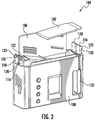
FIG. 2 depicts a portion of a portable pill dispenser in accordance with one or more embodiments of the disclosure. -
FIG. 3 depicts a portion of a portable pill dispenser in accordance with one or more embodiments of the disclosure. -
FIG. 4 depicts a portion of a portable pill dispenser in accordance with one or more embodiments of the disclosure. -
FIG. 5 depicts a tool in accordance with one or more embodiments of the disclosure. -
FIG. 6 depicts a portion of a portable pill dispenser in accordance with one or more embodiments of the disclosure. -
FIG. 7 depicts a ramp in accordance with one or more embodiments of the disclosure. -
FIG. 8 depicts a portion of a portable pill dispenser in accordance with one or more embodiments of the disclosure. -
FIG. 9 depicts a portion of a portable pill dispenser in accordance with one or more embodiments of the disclosure. -
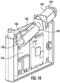
FIG. 10 depicts a portion of a portable pill dispenser in accordance with one or more embodiments of the disclosure. -
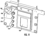
FIG. 11 depicts a portion of a portable pill dispenser in accordance with one or more embodiments of the disclosure. -
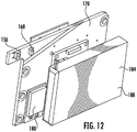
FIG. 12 depicts a portion of a portable pill dispenser in accordance with one or more embodiments of the disclosure. -
FIG. 13 schematically depicts a communication network in accordance with one or more embodiments of the disclosure. -
FIG. 14 depicts a portable pill dispenser in accordance with one or more embodiments of the disclosure. -
FIG. 15 depicts a portable pill dispenser in accordance with one or more embodiments of the disclosure. -
FIG. 16 depicts a portable pill dispenser in accordance with one or more embodiments of the disclosure. -
FIG. 17 depicts a portable pill dispenser in accordance with one or more embodiments of the disclosure. -
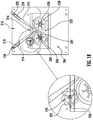
FIG. 18 depicts a portion of a portable pill dispenser in accordance with one or more embodiments of the disclosure. -
FIG. 19 depicts a portion of a portable pill dispenser in accordance with one or more embodiments of the disclosure. -
FIG. 20 depicts a dispensing sequence in accordance with one or more embodiments of the disclosure. -
FIG. 21 depicts a dispensing sequence in accordance with one or more embodiments of the disclosure. -
FIG. 22 depicts a portable pill dispenser in accordance with one or more embodiments of the disclosure. -
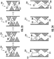
FIG. 23 depicts a dispensing sequence in accordance with one or more embodiments of the disclosure. -
FIG. 24 depicts a dispensing sequence in accordance with one or more embodiments of the disclosure. - Described below are embodiments of portable pill dispensers (as well as individual components of the portable pill dispensers). As used herein, the term "pills" refers to tablets, capsules, gel caps, and other dosage units known in the art for administering pharmaceutical agents (or placebos of the same). Typically, the pill is a solid oral dosage known in the art. Methods of manufacturing and using the portable pill dispensers are also disclosed. In some instances, the portable pill dispensers may be used in clinical trials. For example, one or more of the participants (patients) in the client trial may be provided with the portable pill dispensers. Information from the portable pill dispensers may be monitored, recorded, and provided to the operator of the clinical trial. The information provided by the portable pill dispensers may help ensure the integrity of the clinical trial. The information provided by the portable pill dispensers may be highly useful information, such as when the patient takes the pills, information which may be far more accurate than relying of the patient's own recollection and independent recordkeeping. Moreover, the operator of the clinical trial may remotely monitor, record, control, modify, and/or adjust the dispensing capabilities of the portable pill dispensers as necessary in order to carry out the clinical trial as efficiently and cost-effectively as possible. In other embodiments, the portable pill dispensers are used by patients not in a clinical trial, such as in dispensing any approved drug to a patient as prescribed by his or her physician. The portable pill dispenser may be used in any setting to monitor, record, and/or adjust the dispensing of a drug.
- The portable pill dispensers may prevent the misuse of medications by intended users and also ensure correct dispensing of prescription medications. For example, the portable pill dispensers may monitor and record the dispensing of prescription medications to intended users and verify that medications stored therein are not taken in excess (i.e., abused) and are only taken at the prescribed interval and dose. In addition, the portable pill dispensers may verify that medications stored therein are removed only by the patient or another authorized person in order to prevent drug abuse, diversion, and/or mistake. The portable pill dispensers can aid the patient to take (e.g., ingest) his or her medication as directed (as prescribed) by his or her physician.
- The term "portable" refers to a pill dispenser that may be easily carried by a user, such as in one of his or her hands, or within a pocket of his or her clothing. In this manner, the size and shape of the portable pill dispenser may enable a user to carry the portable pill dispenser on his or her person in essentially the same way that a current model mobile phone or smart phone is typically carried by a person. That is, the overall dimensions of the portable pill dispenser are such that a user can easily hold it in one hand, or can readily carry it, for example, in a pocket of his or her jacket, pants, shirt, shorts, or overcoat, or in a handbag or backpack. In this manner, a user may keep the portable pill dispenser on their person, e.g., in a concealed manner, throughout the day. In some instances, the user may operate the portable pill dispenser with one hand. In other instances, the user may hold the portable pill dispenser in one hand and operate it with the other hand.
-
FIG. 1 schematically depicts aportable pill dispenser 100. Theportable pill dispenser 100 includes acontainer 102. Thecontainer 102 is configured to house at least one pill therein. In some instances, a number of pills (e.g., 2 to 100 or more pills) are stored within thecontainer 102. Thecontainer 102 may be transparent or opaque. Thecontainer 102 may be disposable or reusable. Thecontainer 102 may be any suitable size, shape, or configuration. Thecontainer 102 may include a container label on an exterior surface thereof. For example, thecontainer 102 may include a prescription label thereon. The prescription label may identify the pills therein, provide instructions to the patient, provide a medication dosage regimen, provide patient information, provide doctor information, provide warnings, and/or provide emergency instructions, or the like. The information may be in the form of text, a barcode, and/or a data chip. Any information may be included on the container label and/or on thecontainer 102 itself. - The
container 102 is attachable to ahousing 104. As depicted inFIGS. 1-3 , thehousing 104 may include arear portion 106 that is attached to afront portion 108. Thefront portion 108 and therear portion 106 may be screwed, welded, or the like. In certain embodiments, thefront portion 108 and therear portion 106 may be a single unitary body. In some instances, therear portion 106 and thefront portion 108 are screwed together. For example, thefront portion 108 and therear portion 106 may include one ormore bores 110 andcorresponding screws 112. Therear portion 106 and thefront portion 108 may include one or more internal platforms, frames, lips, walls, attachment points or the like for attaching, aligning, securing, and/or positioning the various components disposed within thehousing 104. Thehousing 104 may be any suitable size, shape, or configuration. - In certain embodiment, the
portable pill dispenser 100 includes anattachment mechanism 114 configured to secure thecontainer 102 to thehousing 104. As depicted inFIG. 2 , theattachment mechanism 114 comprises a pair of firstresilient tabs 116 extending from thefront portion 108 on each side thereof. Theattachment mechanism 114 also comprises a pair of secondresilient tabs 118 extending from therear portion 106 on each side thereof. In some instances, the first and second resilient tabs includelips 120. Thelips 120 are formed by atriangular protrusion 122 projecting outward from a distal tip of the first and secondresilient tabs lips 120 are configured to mate withapertures 124, as depicted inFIG. 4 , in the side of thecontainer 102 to secure thecontainer 102 to thehousing 104. The shape of thetriangular protrusions 122 causes the first andsecond tabs container 102 is pressed together with thehousing 104. Once thetriangular protrusions 122 are aligned with theapertures 124, the first and secondresilient tabs lips 120 to engage an edge of theapertures 124 to secure thecontainer 102 to thehousing 104. In some instances, tamper stickers may be placed over theapertures 124 to prevent thecontainer 102 from being removed from thehousing 104. -
FIG. 5 depicts atool 126 for removing thecontainer 102 from thehousing 104. Thetool 126 includes amain body 128 with a pair ofprotrusions 130 extending therefrom. Theprotrusions 130 are sized and shaped to correspond to theapertures 124 so as to press against thetriangular protrusions 122 to bend the first and second resilient tabs inward 116, 118, thereby disengaging thelips 120 from theapertures 124, which enables thecontainer 102 to be removed from thehousing 104. In some instances, only an authorized person (such as a pharmacist, physician, or clinical trial operator) may have access to thetool 126. Any type of tamper resistance attachment mechanism may be used herein. In some instances, for additional security, a removable tamper resistant housing may encase theportable pill dispenser 100. The tamper resistant housing may be smash proof. For example, the tamper resistant housing may form a metal jacket about the portable pill dispenser. The tamper resistant housing may be used when transporting certain narcotics or the like. - The
portable pill dispenser 100 is configured to dispense pills. For example, as depicted inFIG. 1 , thefront portion 108 includes adispensing opening 132. In addition, as depicted inFIGS. 6-8 , adispensing mechanism 134 and aramp 136 are disposed within thehousing 104. Theramp 136 is configured to guide the pills from thecontainer 102 to thedispensing mechanism 134. In some instances, theramp 136 guides one pill at a time to thedispensing mechanism 134. That is, theramp 136 is sized and shaped to align one pill into thedispensing mechanism 134 at a time. In this manner, theramp 136 includes aninlet 138 facing thecontainer 102 and an outlet facing 140 thedispensing mechanism 134. The size and shape of theinlet 138 and theoutlet 140 may vary depending on the pills being dispensed. Theramp 136 may include one or more angled portions so as to use gravity to encourage the pills to slide into thedispensing mechanism 134. For example, theramp 136 may function as a funnel directing one pill at a time to thedispensing mechanism 134. In some instances, theramp 136 may be at least partially formed by aledge 142 extending from therear portion 106. In other instances, the ledge 42 may be omitted. Theramp 136 may be any size, shape, or configuration. - In some instances, the
ramp 136 may comprise aremovable ramp insert 144. Theremovable ramp insert 144 may be removed and replaced with a ramp having a different size, shape, or configuration to accommodate pills of varying sizes and/or shapes. For example, theremovable ramp insert 144 may be removably attached to therear portion 106. In this manner, theportable pill dispenser 100 may be customized for pills of different shapes and sizes. - The
dispensing mechanism 134 is configured to dispense the pills from the container to thedispensing opening 132. The dispensing mechanism comprises 134 a motor 146 (e.g., an electric motor) in mechanical communication with arotating barrel 148. Themotor 146 may be in direct or indirect (e.g., via one or more gears) mechanical communication with therotating barrel 148. Themotor 146 and therotating barrel 148 may be positioned beneath theramp 136. In this manner, therotating barrel 148 is positioned about theoutlet 140 of theramp 136. Therotating barrel 148 is angled downward to facilitate dispensing of the pills. Therotating barrel 148 comprises acavity 150 configured to receive the pill therein. Thecavity 150 may be sized and shaped to accommodate one pill at a time. In some instances, therotating barrel 148 may include a number of cavities. In this manner, rotation of therotating barrel 148 dispenses the pill within thecavity 150 to apassageway 152, which leads to thedispensing opening 132. In certain embodiments, once all of the pills have been dispensed, thecontainer 102 may be removed from thehousing 102 and anew container 102 may be attached thereto. In other instances, thecontainer 102 may be refilled. - In order to accommodate pills of varying sizes and/or shapes, a
removable insert 154 may be disposed within thecavity 150. Theremovable insert 154 may adjust the size and/or shape of thecavity 150. In this manner, depending of the pills being dispensed, different sized and/or shapedremovable inserts 154 may be disposed within thecavity 150 to adjust theportable pill dispenser 100 to accommodate a variety of pills. Theremovable insert 154 may be any size, shape, or configuration. In this manner, theportable pill dispenser 100 may be customized for different pills. - As depicted in
FIG. 9 , theportable pill dispenser 100 also may include apill sensor 156 disposed within thehousing 104. Thepill sensor 156 may be located anywhere within thehousing 104. For example, thepill sensor 156 may be disposed within or adjacent to thecavity 150, within or adjacent to thepassageway 152, and/or within or adjacent to thedispensing opening 132. Thepill sensor 156 is configured to detect thepill 158 being dispensed to thedispensing opening 132. In some instances, thepill sensor 156 may detect thepill 158 within thecavity 150, passing from thecavity 150 to thepassageway 152, and/or from thepassageway 152 to thedispensing opening 132. Any type ofpill sensor 156 may be used. In one embodiment, thepill sensor 156 may be a photo reflective sensor, which may detect thepill 158 based on light reflection from thepill 158 compared to light reflection from therotating barrel 148. The wavelength of light is chosen to maximize the signal difference between thepill 158 and therotating barrel 148. By way of example, thedispensing mechanism 134 can be optimized to maximally reflect the chosen wavelengths of light while thepill 158 maximally absorbs the chosen wavelengths of light. Various mechanisms that can be used to maximize the differences in absorption or reflection of light can include reflection, refraction, light scatter, light diffusion, surface textures, dispenser color, dispenser material choice, dispenser coatings, material fluorescence, or the like. In other instances, thepill sensor 156 may be a limit switch or the like. Moreover, any number ofpill sensors 156 may be used. For example,multiple pill sensors 156 can detect the movement of thepill 158 at each stage from thecontainer 102 to thedispensing opening 132. - In some instances, as depicted in
FIG. 10 , arotation sensor 160 is disposed within thehousing 104 about therotating barrel 148. Therotation sensor 160 is configured to detect the annular position of therotating barrel 148. Therotation sensor 160 may be particularly useful in determining the location of thecavity 150. In some instances, therotation sensor 160 may be a trigger sensor (e.g., limit switch) that engages anedge 162 of therotating barrel 148 as it rotates. Other types ofrotation sensors 160 may be used, including, but not limited to, a magnetic sensor or a photo reflector sensor configured to detect a sticker or other indicia on therotating barrel 148. Moreover, atachometer 164 may be disposed about themotor 146. Therotation sensor 160 and thetachometer 164 may collectively determine the annular position of therotating barrel 148. In some instances, a tachometer, a limit switch, a photo reflective sensor, and/or a motor current sensor may be used to detect a "jam" and take appropriate action. For instance, if the motor current is high such that the rotating barrel should be spinning, and the photo reflective sensor and/or limit switch do not sense the barrel rotating, the motor may be instructed to run in reverse or to run back-and-forth several times. In addition, an error message may be displayed or a wireless signal may be sent to a smartphone or other companion electronic device. - Referring back to
FIG. 1 , the portable pill dispensing 100 includes averification mechanism 166. Theverification mechanism 166 is configured to activate thedispensing mechanism 134 upon verification of the identity of the user. In certain embodiments, theverification mechanism 166 comprises abiometric sensor 168. For example, theverification mechanism 166 may be a fingerprint reader, a retina reader, or the like. Thebiometric sensor 168 is disposed on thefront portion 108 and includes a finger print reader. In other instances, theverification mechanism 166 may include a touch pad that a user enters a code or swipes a pattern. Any type ofverification mechanism 166 may be used to limit and/or verify dispensing of the pills. In a preferred embodiment, theverification mechanism 166 will only enable thedispensing mechanism 134 to dispense a pill upon verifying the identity of the user. - As depicted in
FIGS. 1 and9-12 , acontrol panel 170 is disposed within thehousing 104. Thecontrol panel 170 comprises a printed circuit board having one or more electrical components thereon or in communication therewith. Thecontrol panel 170 includes a memory, circuitry, and at least on processor to execute the various functions described herein. In some instances, the electrical components of thecontrol panel 170 may be incorporated into thecontrol panel 170 and/or be in electrical communication with thecontrol panel 170. For example, theverification mechanism 166 anddispensing mechanism 134 may be in electrical communication with thecontrol panel 170. In addition, an accelerometer 172, one or morelight indicators 174, a speaker 176, amute button 178, awireless communication module 180, anelectrical connection port 182, one ormore batteries 184, a battery charging connection port, an onboard internal clock, a vibration motor, and/or a geoposition transceiver (e.g., GPS transceiver) may also be in electrical communication with thecontrol panel 170. The various electrical components may be disposed within thehousing 104 and/or be accessible from outside of thehousing 104. - The accelerometer 172 may determine the orientation of the
portable pill dispenser 100. For example, in order to ensure the proper dispensing of the pills, thecontrol panel 170 may not activate thedispensing mechanism 134 unless theportable pill dispenser 100 is in a substantially upright position as determined by the accelerometer 172. The speaker 176 (or other audible device) may provide alerts to the user, such as when to take their medication. The speaker 176 may provide any type of alert, including, but not limited to power alerts, verification alerts, unauthorized access alerts, dispensing alerts (including alerting the user that it is time to take their medication), incoming messages alerts, connectivity alerts, and/or change in medication regimen alerts, etc. The vibration motor also may similarly provide alerts to the user by vibrating theportable pill dispenser 100 when activated. Themute button 178 may enable to user to temporarily (or permanently) turn off (or mute) the alerts. Themute bottom 178 also may deactivate the vibration motor. Thelight indicators 174 may provide various alerts to the user, such as but not limited to, power alerts, verification alerts, unauthorized access alerts, dispensing alerts, incoming messages alerts, connectivity alerts, and/or change in medication regimen alters, etc. Thelight indicators 174 may be multi-colored LED lights. Thebatteries 184 may power the various electrical components. For example, asecondary battery 186 may power an internal clock associated with thecontrol panel 170, while aprimary battery 188 may power all of the other electrical components. In some instances, the internal clock may ensure that the dose information is properly time-stamped. The geoposition transceiver may enable tracking of the portable pill dispenser in cases of theft or loss. In addition, the geoposition transceiver may track the location where pills are being dispensed. Theelectrical connection port 182 and/or battery charging port may enable theportable pill dispenser 100 to be charged and/or connected to other devices or networks. In some instances, theelectrical connection port 182 is a USB port or the like. Similarly, thewireless communication module 180 may enable theportable pill dispenser 100 to be connected to other devices or networks. In some instances, the wireless communication module may include Bluetooth capabilities, WIFI capabilities, satellite capabilities, a transmitter, or the like. Thewireless communication module 180 may use any wireless communication protocol. Theelectrical connection port 182 and/or thewireless communication module 180 may enable theportable pill dispenser 100 to be connected to other devices for programming, troubleshooting, and/or data download. -
FIG. 13 depicts theportable pill dispenser 100 communicating over anetwork 190. Theportable pill dispenser 100 may include wireless capabilities. For example, theportable pill dispenser 100 may communicate over thenetwork 190 with other devices by way of thewireless communication module 180. In other instances, theportable pill dispenser 100 may communicate over the network with other devices through a hard connection by way of theelectrical communication port 182. Theportable pill dispenser 100 may communicate with one or more computing devices 192 associated with a doctor's office, a hospital, a pharmacist, a caretaker, a clinical trial operator, etc. Theportable pill dispenser 100 may communication with any suitable device or persons associated therewith. In addition, one or more thirdparty computing devices 194 may monitor theportable pill dispenser 100 and/or collect information associated with theportable pill dispenser 100 over thenetwork 190. In this manner, a medication regimen may be tracked to determine if it is being properly followed. Moreover, the medication regimen may be modified remotely. That is, the ability of theportable pill dispenser 100 to dispense pills may be adjusted remotely by a pharmacist, a caretaker, or a clinical trial operator, etc. -
FIGS. 14-24 depict additional embodiments of aportable pill dispenser 200. The embodiments described inFIGS. 14-24 may be incorporated into the embodiments described inFIGS. 1-13 and vice versa. Theportable pill dispenser 200 may include acontainer 202 configured to house one ormore pills 204 therein. In some instances, thecontainer 202 is reusable or disposable. Theportable pill dispenser 200 also may include ahousing 205 attachable to thecontainer 202. Thehousing 205 may include adispensing mechanism 206 therein. Any type ofdispensing mechanism 206 may be used. Thedispensing mechanism 206 may be configured to dispense at least one of thepills 204 from thecontainer 202 to adispensing opening 208. In some instances, thehousing 205 reusable. That is, once thepills 204 have been dispensed, thedisposable container 202 may be removed from thehousing 205 and a newdisposable container 202 may be attached thereto. - The
container 202 may include a container label. For example, thecontainer 202 may include a prescription label thereon. The prescription label may identify the pills therein, provide instructions to the patient, provide a medication regimen, provide patient information, provide doctor information, provide warnings, and/or provide emergency instructions, or the like. The information may be in the form of text and/or a barcode. Any information may be included on the container and/or label. - In some instances, the
container 202 may include a data chip (or other electronic storage device, such as a memory card or the like). The data chip may include any information included in the prescription label. The information associated with the data chip may be encrypted. In some instances, thecontainer 202 and/or thehousing 205 may include an electronic display, which may display information from the data chip. In addition, the data chip may provide information (such as pill type, a medication dosage regimen, etc.) to a controller associated with thedispensing mechanism 206 so as to control the dispensing of thepills 204. In this manner, thecontainer 202 may communicate (wirelessly and/or by way of a direct connection) to thedispensing mechanism 206. - In certain embodiments, the
container 202 and/or thehousing 205 may include a radio with any suitable transceiver component(s) for transmitting or receiving radio frequency (RF) signals. In this manner, theportable pill dispenser 200 may include wireless capabilities. Theportable pill dispenser 200 may be WIFI, cellular, satellite, or the like compatible. For example, theportable pill dispenser 200 may communicate over a network with other devices. For example, theportable pill dispenser 200 may communicate with one or more computing devices associated with a doctor's office, a hospital, a pharmacist, a caretaker, a clinical trial operator, etc. Theportable pill dispenser 200 may communication with any suitable device or persons associated therewith. In addition, third parties may monitor theportable pill dispenser 200 and/or collect information associated with theportable pill dispenser 200 over a network. For example, a medication regimen may be tracked to determine if it is being properly followed. The medication regimen also may be modified remotely. - A
funnel 210 may be configured to direct at least one of thepills 204 to thedispensing mechanism 206. In certain embodiments, as depicted inFIG. 18 , thefunnel 210 includes afirst arm 212 and asecond arm 214. In some instances, thefirst arm 212, thesecond arm 214, or both are adjustable relative to each other in order to adjust afunnel opening 216 therebetween. In this manner, thefunnel 210 may be adjusted to allow onepill 204 at a time through thefunnel opening 216. For example, thefirst arm 212, thesecond arm 214, or both may comprise arespective funnel slot 218 slidably positioned about arespective funnel peg 220. In this manner, thefirst arm 212 and/or thesecond arm 214 may be adjusted by sliding thefirst arm 212 and/or thesecond arm 214 about therespective funnel peg 220. Thefirst arm 212 and/or thesecond arm 214 may be adjusted to accommodate different pill sizes. In other instances, one or both of the funnel arms may be fixed. In yet other instances, thefunnel 210 may be omitted. - In certain embodiment, as depicted in
FIGS. 23 and 24 , thefunnel 210 may include atorturous path 211 to ensure thatcertain pills 204 are properly oriented for dispensing. For example,elongated pills 213 may not pass through thetorturous path 211 unless oriented in a certain configuration, such as sideways. In some instances, thetorturous path 211 may include a winding path with several switchbacks leading to thefunnel opening 216. The winding path may only enable pills in a certain orientation to pass through thefunnel 210 to thefunnel opening 216. In some instances, a user may shake theportable pill dispenser 200 to jostle thepills 204 into the proper orientation so that they can pass down thetorturous path 211. In some instances, thetorturous path 211 may form thefunnel 210. In other instances, thetorturous path 211 may directpills 204 to thefunnel 210. In yet other instances, thefunnel 210 may directpills 204 to thetorturous path 211. - Referring back to
FIG. 18 , theportable pill dispenser 200 may include anagitation device 222 in communication with at least one of thefirst arm 212, thesecond arm 214, or a combination thereof to impart motion thereto. For example, theagitation device 222 may be a ratchet gear that rotates to vibrate or otherwise move thefirst arm 212 and/or thesecond arm 214. Theagitation device 222 may ensure the one ormore pills 204 slide down thefunnel 210. In some instances, theagitation device 222 is adjustable. For example, theagitation device 222 may include ahub 224 slidably positioned within anagitation slot 226. Theagitation device 222 may be adjusted by sliding thehub 224 about theagitation slot 226. In this manner, theagitation device 222 may be adjusted to accommodate different pill sizes and/or funnel arrangements. In some instances, theagitation device 222 may be omitted. - In certain embodiments, the
dispensing mechanism 206 comprises a firstrotatable hub 228 and a secondrotatable hub 230 positioned about thefunnel opening 216. In some instances, the firstrotatable hub 228, the secondrotatable hub 230, or both are adjustable relative to each other in order to adjust arotatable hub opening 232 therebetween. For example, the firstrotatable hub 228 and/or the secondrotatable hub 230 may be slidably positioned about a respectiverotatable hub slot 234. In this manner, the firstrotatable hub 228 and/or the secondrotatable hub 230 may be adjusted by sliding the firstrotatable hub 228 and/or the secondrotatable hub 230 about the respectiverotatable hub slot 234. The firstrotatable hub 228 and/or the secondrotatable hub 230 may be adjusted to accommodate different pill sizes. Rotation of the firstrotatable hub 228 and the secondrotatable hub 230 may move at least one of the one ormore pills 204 from the funnel opening 216 to thedispensing opening 208. In some instances, thedispensing mechanism 206 dispenses one pill at a time. - As depicted in
FIG. 17 , apassageway 233 may be disposed between the firstrotatable hub 228 and the secondrotatable hub 230 and thedispensing opening 208. In this manner, the firstrotatable hub 228 and the secondrotatable hub 230 may move at least one of the one ormore pills 204 from the funnel opening 216 to thepassageway 233. For example, thedispensing mechanism 206 dispenses one pill at a time. In some instances, thepassageway 233 includes alever 235 that blocks pills from reaching the dispensingopening 208. As discussed below, thelever 235 may pivot to allow the pills to travel down thepassageway 233 to thedispensing opening 208 once the user and/or medication regimen has been verified. - Referring back to
FIG. 18 , in some instances, the firstrotatable hub 228, the secondrotatable hub 230, or a combination thereof are in mechanical communication with theagitation device 222. In this manner, rotation of the firstrotatable hub 228, the secondrotatable hub 230, and/or theagitation device 222 may drive (e.g., rotate) the others or vice versa. Moreover, in certain embodiments, as depicted inFIG. 17 , adrive wheel 236 is in mechanical communication with at least one of the firstrotatable hub 228, the secondrotatable hub 230, and/or theagitation device 222. In addition, thedrive wheel 236 may be in mechanical communication with a motor or the like. Thedrive wheel 236 may impart motion (directly or indirectly) to the firstrotatable hub 228, the secondrotatable hub 230, and/or theagitation device 222. In other instances, the motor 225 may be attached directly to the firstrotatable hub 228, the secondrotatable hub 230, and/or theagitation device 222. In some instances, the motor may be an electric motor in communication with a battery. A controller may be in communication with the battery and/or the motor to control the dispensing process. - In some instances, as depicted in
FIG. 18 , afirst foam wheel 238 is positioned about the firstrotatable hub 228. Similarly, asecond foam wheel 240 may be positioned about the secondrotatable hub 230. Thefirst foam wheel 238 and thesecond foam wheel 240 may facilitate dispensing of at least one of the one ormore pills 204 by the firstrotatable hub 228 and the secondrotatable hub 230. In some instances, thedispensing mechanism 206 dispenses one pill at a time. Thefirst foam wheel 238 and thesecond foam wheel 240 may be the same or different sizes. In some instances, thefirst foam wheel 238 and/or thesecond foam wheel 240 may be omitted. - In another embodiment, as depicted in
FIGS. 19-21 , thedispensing mechanism 206 includes arotating barrel 242 positioned about thefunnel opening 216. Therotating barrel 242 may include at least onecavity 244 configured to receive at least one of the one ormore pills 204 therein from thefunnel opening 216. In some instances, a number ofcavities 244 may be disposed within therotating barrel 242. The at least one cavity may be sized to fit one pill therein. In this manner, thedispensing mechanism 206 may dispense one pill at a time. Therotating barrel 242 may rotate the at least onecavity 244 from the funnel opening 216 to thedispensing opening 208. In this manner, rotation of thebarrel 242 may move at least one of the one ormore pills 204 from the funnel opening 216 to thedispensing opening 208. As noted above, atorturous path 211 may be incorporated to ensure that thepills 204 are in the proper orientation for dispensing into the at least onecavity 244 in therotating barrel 242. In some instances, apassageway 233 may be positioned between therotating barrel 242 and thedispending opening 208. Thedispensing mechanism 206 may include amotor 246 in direct or indirect (e.g., via one or more gears) mechanical communication with therotating barrel 242. In some instances, themotor 246 may be an electric motor in communication with abattery 248. Acontroller 250 may be in communication with thebattery 248 and/or themotor 246 to control the dispensing process.FIGS. 20 and21 depict therotating barrel 242 making a full rotation to dispense at least one of the one ormore pills 204. - Referring back to
FIGS. 14-17 , theportable pill dispenser 200 may include anattachment mechanism 252 configured to secure thecontainer 202 to thehousing 205. In some instances, theattachment mechanism 252 comprises at least one pivotinglever 254 positioned about thehousing 205. The at least one pivotinglever 254 may be configured to mate with at least onepin 256, which may be disposed about thecontainer 202. The at least one pivotinglever 254 may include arelease bottom portion 258. In some instances, a tool may be required to detach thecontainer 202 from thehousing 205. For example, a lock pin shear bar 260 may prevent thecontainer 202 from detaching from thehousing 205. In this manner, only an authorized person (such as a pharmacist) may detach thecontainer 202 from thehousing 205. Any type of tamper resistance attachment mechanism may be used herein. - In addition, a
verification mechanism 262 may be configured to verify access to thedispensing opening 208 and/or activate thedispensing mechanism 206. That is, theverification mechanism 262 may only provide access to thedispensing opening 208 to a verified user and/or may only activate thedispensing mechanism 206 upon verification of the user. In some instances, theverification mechanism 262 is a biometric locking mechanism. For example, theverification mechanism 262 may be a fingerprint reader, a retina reader, or the like. In other instances, theverification mechanism 262 may include a touch pad that a user enters a code into. Any type of verification mechanism may be used herein to limit and/or verify access to thedispensing opening 208. - The
portable pill dispenser 200 may include one or more sensors disposed about thecontainer 202, thehousing 205, and/or thedispensing mechanism 206. For example, the one or more sensors may be disposed within thecontainer 202 to detect the presence of the one ormore pills 204. The one or more sensors also may be positioned adjacent to the dispensing mechanism 206 (on the funnel side and/or the dispensing opening side) to detect if and how many pills may have been dispensed. In addition, the one or more sensors may be disposed about the dispensingopening 208. The one or more sensors may be configured to detect the presence of at least one of the one or more pills at any of the stages of the dispensing process. In one embodiment, the detection mechanism is based on light reflection from the pill compared to light reflection from the dispensing mechanism (barrel). The wavelength of light is chosen to maximize the signal difference between the pill and the dispenser. By way of example, the dispenser can be optimized to maximally reflect the chosen wavelengths of light while the pill maximally absorbs the chosen wavelengths of light. Various mechanisms that can be used to maximize the differences in absorption or reflection of light can include reflection, refraction, light scatter, light diffusion, surface textures, dispenser color, dispenser material choice, dispenser coatings, material fluorescence, and the like. - In certain embodiments, as depicted in
FIG. 22 , thecontainer 202 may be disposed within thehousing 205. For example, thecontainer 202 may take the form of acartridge 264 that is disposed within thehousing 205. For example, thehousing 205 may include anouter shell 266 with anopening 268. Theopening 268 may be covered by a pivotinglid 270. Thecartridge 264 may be inserted into theopening 268 and thelid 270 may be pivoted shut. Thelid 270 may be secured shut by any tamper proof attachment means. Thecontainer 202 and thehousing 205 may be arrangement in any manner.
Claims (13)
- A portable pill dispenser (100, 200), comprising:a container (102, 202) configured to house at least one pill (158, 204) therein;a housing (104, 205) attachable to the container (102, 202), wherein the housing (104, 205) comprises a dispensing opening (132, 208);a dispensing mechanism (134, 206) disposed within the housing (104, 205), wherein the dispensing mechanism (134, 206) is configured to dispense the at least one pill (158, 204) from the container (102, 202) to the dispensing opening (132, 208);a ramp (136) disposed within the housing (104, 205), wherein the ramp (136) is configured to direct the at least one pill to the dispensing mechanism (134, 206);a verification mechanism (166, 262) disposed about the housing (104, 205), wherein the verification mechanism (166, 262) is configured to activate the dispensing mechanism (134, 206); anda control panel (170) disposed within the housing (204, 205), wherein the control panel (170) is in electrical communication with the dispensing mechanism (134, 206) and the verification mechanism (166, 262),whereinthe dispensing mechanism (134, 206) comprises a motor (146) in mechanical communication with a rotating barrel (148), wherein the rotating barrel (148) comprises at least one cavity (150) configured to receive the at least one pill (158, 204) therein, characterised in that the rotating barrel (148) is positioned at an outlet (140) of the ramp (136), and wherein the rotating barrel (148) is angled downward such that rotation of the rotating barrel (148) dispenses the at least one pill (158, 204) to the dispensing opening (132, 208).
- The portable pill dispenser of claim 1, further comprising a rotation sensor (160) disposed within the housing (104, 205) about the rotating barrel (148) and in electrical communication with the control panel (170), wherein the rotation sensor (160) is configured to detect the annular position of the rotating barrel (148).
- The portable pill dispenser of claim 1, further comprising a tachometer (164) disposed about the motor (146) and in electrical communication with the control panel (170).
- The portable pill dispenser of claim 1, further comprising a removable insert (154) disposed within the at least one cavity (150) for adjusting the size and/or shape of the at least one cavity (150).
- The portable pill dispenser of claim 1, further comprising a pill sensor (156) disposed within the housing (104, 205) and in electrical communication with the control panel (170), wherein the pill sensor (156) is configured to detect the at least one pill (158, 204) being dispensed to the dispensing opening (132, 208).
- The portable pill dispenser of claim 1, wherein the ramp (136) comprises a removable ramp insert (144).
- The portable pill dispenser of claim 1, wherein the verification mechanism (166, 262) comprises a biometric sensor (168).
- The portable pill dispenser of claim 1, further comprising:an accelerometer (172) disposed within the housing and in electrical communication with the control panel (170);one or more light indicators (174) disposed about the housing (104, 205) and in electrical communication with the control panel (170);a speaker (176) disposed within the housing (104, 205) and in electrical communication with the control panel (170);a mute bottom (178) disposed about the housing (104, 205) and in electrical communication with the control panel (170);an electrical connection port (182) disposed about the housing (104, 205) and in electrical communication with the control panel (170);at least one battery (184) disposed within the housing (104, 205); and/ora vibration motor disposed within the housing (104, 205) and in electrical communication with the control panel 170).
- The portable pill dispenser of claim 1, further comprising a wireless communication module (180) disposed within the housing (104, 205) and in electrical communication with the control panel (170).
- The portable pill dispenser of claim 1, wherein the control panel (170) comprises a printed circuit board having one or more electrical components.
- The portable pill dispenser of claim 1, further comprising an attachment mechanism (114) configured to secure the container (102, 202) to the housing (104, 205), wherein the attachment mechanism (114) comprises:at least one resilient tab (116, 118) extending from the housing (104, 205), wherein the at least one resilient tab (116, 118) comprises a lip (120); andat least one aperture (124) in the container (102, 202), wherein the at least one aperture (124) is configured to mate with the at least one lip (120) to secure the container (102, 202) to the housing (104, 205).
- The portable pill dispenser of claim 11, further comprising a tool (126) having at least one protrusion (130) configured to press against the lip (120) to bend the at least one resilient tab (116, 118) and remove the lip (120) from the at least one aperture (124) to disengage the container (102, 202) from the housing (104, 205).
- A method for dispensing the at least one pill from the portable pill dispenser of claim 1, the method comprising:verifying a user identity with the verification mechanism;dispensing the at least one pill to the dispensing opening by way of the dispensing mechanism; andtransmitting by a wireless communication module, an electrical connection port, or a combination thereof information associated with the dispensing of the at least one pill to a central database.
Applications Claiming Priority (2)
| Application Number | Priority Date | Filing Date | Title |
|---|---|---|---|
| US201562143096P | 2015-04-04 | 2015-04-04 | |
| PCT/US2016/024435 WO2016164187A1 (en) | 2015-04-04 | 2016-03-28 | Systems and methods for portable pill dispensers |
Publications (2)
| Publication Number | Publication Date |
|---|---|
| EP3280378A1 EP3280378A1 (en) | 2018-02-14 |
| EP3280378B1 true EP3280378B1 (en) | 2019-11-13 |
Family
ID=55699830
Family Applications (1)
| Application Number | Title | Priority Date | Filing Date |
|---|---|---|---|
| EP16715418.6A Active EP3280378B1 (en) | 2015-04-04 | 2016-03-28 | Systems and methods for portable pill dispensers |
Country Status (13)
| Country | Link |
|---|---|
| US (1) | US10792224B2 (en) |
| EP (1) | EP3280378B1 (en) |
| JP (1) | JP2018510002A (en) |
| KR (1) | KR20170134530A (en) |
| CN (1) | CN107438395A (en) |
| AU (1) | AU2016246402A1 (en) |
| BR (1) | BR112017021131A2 (en) |
| CA (1) | CA2980576A1 (en) |
| IL (1) | IL254414A0 (en) |
| MX (1) | MX2017012083A (en) |
| RU (1) | RU2017133606A (en) |
| SG (1) | SG11201707637SA (en) |
| WO (1) | WO2016164187A1 (en) |
Families Citing this family (30)
| Publication number | Priority date | Publication date | Assignee | Title |
|---|---|---|---|---|
| USD242591S (en) * | 1975-07-09 | 1976-12-07 | Donald Leroy Hurd | Rack for pocketbooks, magazines and the like |
| US9785750B2 (en) * | 2015-07-11 | 2017-10-10 | ONEWORLD DESIGN & Manufacturing Group, LTD | Medicine organizer |
| MX2018012393A (en) | 2016-04-11 | 2019-05-30 | Firstenergy Ventures Corp | Material dispenser and notification system. |
| US20180075216A1 (en) * | 2016-09-14 | 2018-03-15 | Lloyd Cleveland Nurse | Real-time universal medication management device with locking and metering, and process for using the same |
| BR102016025939B1 (en) * | 2016-11-07 | 2023-05-02 | Lótus Medicina Avançada | WEARABLE ELECTROCARDIOGRAPHIC MONITORING (ECG) TECHNOLOGY WITH HERMETIC RESERVOIR FOR MEDICINES AND INTEGRATED MEDICAL MONITORING SYSTEM |
| USD880844S1 (en) * | 2017-02-20 | 2020-04-14 | DoseCue, LLC | Pharmaceutical container |
| US10157265B1 (en) | 2017-09-21 | 2018-12-18 | Rai Strategic Holdings, Inc. | Clinical study product dispensing device |
| US10872482B1 (en) | 2017-11-22 | 2020-12-22 | Alexander Montgomery Colton | Personalized lid for prescription bottles |
| EP3731796B1 (en) | 2017-12-27 | 2023-12-06 | Intent Solutions, Inc. | Systems for portable pill dispensers with various dispensing mechanisms |
| US20190328619A1 (en) | 2018-04-27 | 2019-10-31 | Pilleve, Inc. | Pill dispensing system |
| US11926454B2 (en) | 2018-08-10 | 2024-03-12 | Krafft Industries Llc | Smart containers |
| US11157739B1 (en) | 2018-08-31 | 2021-10-26 | Apple Inc. | Multi-user computer generated reality platform |
| US10442601B1 (en) | 2018-11-15 | 2019-10-15 | King Saud University | Mobile device system for dispensing oral consumables |
| CN109362698A (en) * | 2018-11-23 | 2019-02-22 | 国家电网有限公司 | A new type of bird repelling device |
| WO2020202032A1 (en) | 2019-04-05 | 2020-10-08 | Blue Sky Ventures (Ontario) Inc. | Gating system for accumulating items and related filling machine and methods |
| CN111109988A (en) * | 2020-01-08 | 2020-05-08 | 河北农业大学 | Automatic accurate medicine discharging device |
| US11594094B2 (en) | 2020-01-22 | 2023-02-28 | Parata Systems, Llc | Methods and apparatus for dispensing solid articles |
| USD955227S1 (en) * | 2020-03-10 | 2022-06-21 | Vitavanti IP B.V. | Alarm clock pill dispenser |
| EP4196075A1 (en) * | 2020-08-12 | 2023-06-21 | CVS Pharmacy, Inc. | Modular dispenser for multiple objects |
| US12064040B2 (en) | 2020-11-17 | 2024-08-20 | Gerhart Cullen Becker | Medication container dispenser |
| USD1035263S1 (en) * | 2021-06-07 | 2024-07-16 | Cvs Pharmacy, Inc. | Dispenser base |
| USD1035260S1 (en) * | 2021-06-07 | 2024-07-16 | Cvs Pharmacy, Inc. | Dispenser base |
| USD1036102S1 (en) * | 2021-06-07 | 2024-07-23 | Cvs Pharmacy, Inc. | Dispenser base with patterned surface texture |
| USD1035261S1 (en) * | 2021-06-07 | 2024-07-16 | Cvs Pharmacy, Inc. | Dispenser assembly |
| USD1035262S1 (en) * | 2021-06-07 | 2024-07-16 | Cvs Pharmacy, Inc. | Linked dispenser assemblies |
| USD1035258S1 (en) * | 2021-06-07 | 2024-07-16 | Cvs Pharmacy, Inc. | Dispenser base |
| USD1035259S1 (en) * | 2021-06-07 | 2024-07-16 | Cvs Pharmacy, Inc. | Dispenser assembly |
| US12036185B2 (en) | 2021-07-19 | 2024-07-16 | Optum, Inc. | System and method to count pills |
| GB202310786D0 (en) * | 2023-07-13 | 2023-08-30 | Ondosis Ab | Dispensing device for medication with vibration means |
| US20250386963A1 (en) * | 2024-06-19 | 2025-12-25 | Microchip Technology Incorporated | Straw for testing and preventing consumption of an unsafe beverage |
Family Cites Families (68)
| Publication number | Priority date | Publication date | Assignee | Title |
|---|---|---|---|---|
| US4572403A (en) | 1984-02-01 | 1986-02-25 | Rafael Benaroya | Timed dispensing device for tablets, capsules, and the like |
| US4646936A (en) | 1985-06-21 | 1987-03-03 | Ortho Pharmaceutical Corporation | Pill dispenser |
| US4785969A (en) | 1986-11-10 | 1988-11-22 | Pyxis Corporation | Medication dispensing system |
| US4911327A (en) | 1988-04-12 | 1990-03-27 | Michel Silberfeld | Dispenser |
| DE69425877T2 (en) | 1993-01-04 | 2001-07-26 | Thomas J. Shaw | AUTOMATIC PILL DELIVERY DEVICE |
| CA2130252A1 (en) | 1994-08-16 | 1996-02-17 | Syl Medwid | Automatic medication dispenser |
| US5522525A (en) | 1994-12-02 | 1996-06-04 | Nu-Box, Inc. | Medication dispenser station |
| CA2217220C (en) | 1996-12-03 | 2001-05-01 | Cal Loveless | Automatic prescription pill dispensing system |
| US6529446B1 (en) | 1996-12-20 | 2003-03-04 | Telaric L.L.C. | Interactive medication container |
| US6611733B1 (en) | 1996-12-20 | 2003-08-26 | Carlos De La Huerga | Interactive medication dispensing machine |
| US7978564B2 (en) | 1997-03-28 | 2011-07-12 | Carlos De La Huerga | Interactive medication container |
| US6766219B1 (en) | 1997-05-29 | 2004-07-20 | Gary Marcel Hasey | Apparatus for controlling and monitoring of dispensing of oral medications |
| US6601729B1 (en) | 1999-03-26 | 2003-08-05 | Papp Enterprises, Llc | Automated portable medication radial dispensing apparatus and method using a carrier tape |
| US6234343B1 (en) | 1999-03-26 | 2001-05-22 | Papp Enterprises, Llc | Automated portable medication radial dispensing apparatus and method |
| US6216910B1 (en) | 1999-04-28 | 2001-04-17 | Allen Numerick | Automatic article dispenser |
| US6324123B1 (en) | 2000-02-18 | 2001-11-27 | Chris M. Durso | Medication timer |
| US6625518B2 (en) | 2000-06-22 | 2003-09-23 | Csem Centre Suisse D'electronique Et De Microtechnique Sa | Method supporting administration of a prescribed drug and implementing said method |
| FI121364B (en) | 2000-08-28 | 2010-10-29 | Addoz Oy | A system for delivering pills or capsule-shaped drugs in desired doses |
| US6732884B2 (en) | 2001-02-22 | 2004-05-11 | Douglas A. Topliffe | Bulk medication dispenser and monitoring device |
| ATE456097T1 (en) | 2001-05-22 | 2010-02-15 | Euro Celtique Sa | CONTAINER AND METHOD FOR DISPENSING TRANSDERMAL DOSAGE FORMS |
| JP2005500099A (en) | 2001-06-22 | 2005-01-06 | ロナルド・ディ・セクラ | Medication compliance device and method of using the device |
| KR200250912Y1 (en) | 2001-07-28 | 2001-11-22 | (주)제이브이메디 | Assistance tray for a manual distribution used in medicine sharing and packing device |
| US7896192B2 (en) | 2001-09-19 | 2011-03-01 | Avancen MOD Corp. | Patient controlled timed medication dispenser |
| US6561377B1 (en) | 2001-12-14 | 2003-05-13 | Pearson Research & Development, Llc | Vacuum drum pill counter |
| JP2005518871A (en) | 2002-03-07 | 2005-06-30 | バング・オ・オルフセン・メディコム・アクティーゼルスカブ | Medical dispenser, blister card used in dispenser and method of dispensing medication |
| US20030183642A1 (en) | 2002-03-26 | 2003-10-02 | Kempker Jeffrey A. | Pill dispensing apparatus |
| US20060213921A1 (en) | 2005-03-23 | 2006-09-28 | Gazi Abdulhay | Pill dispensing apparatus |
| US7178688B2 (en) | 2003-01-07 | 2007-02-20 | Naufel Naji C | Portable medication dispenser |
| US7137528B1 (en) | 2003-05-16 | 2006-11-21 | Cry Twenty-Two, Inc. | Automated Meds dispenser system |
| GB2403711A (en) | 2003-07-07 | 2005-01-12 | Gw Pharma Ltd | Drug dispenser with controlled access |
| US7963201B2 (en) | 2003-08-26 | 2011-06-21 | Concept Medical Technologies, Inc. | Medication dispensing method and apparatus |
| US7392918B2 (en) | 2003-10-07 | 2008-07-01 | R.A.M.M., Llc | Method and device for pill dispensing |
| US7108153B2 (en) | 2004-01-22 | 2006-09-19 | Brad Wood | Apparatus, system, and method for a medication access control device |
| CA2578910C (en) | 2004-09-02 | 2015-11-24 | Edwin C. Simpson | Pill dispensing apparatus |
| US7080755B2 (en) | 2004-09-13 | 2006-07-25 | Michael Handfield | Smart tray for dispensing medicaments |
| US7359765B2 (en) * | 2004-09-15 | 2008-04-15 | Varvarelis Nicholas M | Electronic pill dispenser |
| US7747347B2 (en) | 2005-10-03 | 2010-06-29 | Sabal Medical, Inc. | Mobile medication storage and dispensing apparatus |
| US7440817B2 (en) | 2005-10-20 | 2008-10-21 | Liang Fu | Method and control unit for medication administering devices |
| US8636172B2 (en) | 2006-01-05 | 2014-01-28 | Lawrence A. Dunn | Devices, systems and methods for point-of-use medication control |
| US8357114B2 (en) | 2006-01-06 | 2013-01-22 | Acelrx Pharmaceuticals, Inc. | Drug dispensing device with flexible push rod |
| US20080027579A1 (en) | 2006-07-31 | 2008-01-31 | Van Der Hoop Roland Gerritsen | Dosage limiting medication dispensing method and apparatus |
| US8362914B2 (en) | 2007-11-29 | 2013-01-29 | The Invention Science Fund I, Llc | Communication regarding aspects of a dispensed consumable composition |
| EP2231098A2 (en) * | 2007-12-21 | 2010-09-29 | DSM IP Assets B.V. | Device for dispensing solid preparations |
| US8335697B2 (en) | 2008-02-12 | 2012-12-18 | Bio-Tech Medical Software, Inc. | System and method for monitoring medication prescriptions using biometric identification and verification |
| US8392020B2 (en) | 2008-02-29 | 2013-03-05 | Tension International, Inc. | Automated precision small object counting and dispensing system and method |
| US20090223994A1 (en) | 2008-03-06 | 2009-09-10 | Getz George E | Thumb/Fingerprint Activated Pill Dispenser |
| US20090281657A1 (en) | 2008-05-07 | 2009-11-12 | Baeta Corp. | Automatic medication reminder and dispensing device, system , and method therefor |
| EP2355769A1 (en) | 2008-12-12 | 2011-08-17 | CSP Technologies, Inc. | Dispenser |
| US20100318218A1 (en) | 2009-06-15 | 2010-12-16 | Muncy Jr Robert B | Pill Dispenser and Method |
| US20120316897A1 (en) * | 2011-06-10 | 2012-12-13 | AI Cure Technologies, Inc. | Method and Apparatus for Monitoring Medication Adherence |
| US8135497B2 (en) | 2010-01-13 | 2012-03-13 | Joslyn Matthew I | Portable, personal medication dispensing apparatus and method |
| US20110270442A1 (en) | 2010-04-11 | 2011-11-03 | Conley N Sharon | Ambulatory medication on demand dispenser |
| WO2012148976A1 (en) | 2011-04-25 | 2012-11-01 | Access Business Group International Llc | Pill dispenser |
| US10265245B2 (en) | 2011-08-27 | 2019-04-23 | Daniel L. Kraft | Portable drug dispenser |
| US9730860B2 (en) | 2011-11-03 | 2017-08-15 | Pscap, Llc | Pill dispensing assembly |
| US8749379B2 (en) | 2012-01-19 | 2014-06-10 | Carefusion 303, Inc. | Portable medication dispensing containers |
| US8727180B2 (en) * | 2012-02-02 | 2014-05-20 | Compliance Meds Technologies, Llc | Smart cap system |
| US9870450B2 (en) * | 2012-09-11 | 2018-01-16 | Zolo Solutions, Inc. | Drug delivery regulator |
| US9501626B2 (en) | 2013-05-29 | 2016-11-22 | Dafang Zhang | Smart automated pill dispenser |
| AU2014312428B2 (en) * | 2013-08-28 | 2018-10-11 | Gecko Health Innovations, Inc. | Devices, systems, and methods for adherence monitoring and devices, systems, and methods for monitoring use of consumable dispensers |
| US9913778B2 (en) | 2013-12-05 | 2018-03-13 | Sheri Dvorak | Prescription medication security and dispensing systems |
| US9492357B2 (en) | 2014-04-11 | 2016-11-15 | DoseSmart, Inc. | Personal intelligent dispenser |
| US20150379234A1 (en) | 2014-06-26 | 2015-12-31 | Abcd Technology | Medicine dispensing apparatus and method |
| US10022304B2 (en) | 2014-07-25 | 2018-07-17 | Mark DEETER | As-needed, time controlled medication dispenser and methods |
| US20180369070A1 (en) | 2015-06-17 | 2018-12-27 | The Johns Hopkins University | Personalized, tamper-resistant pill dispenser device and method |
| US20170231870A1 (en) | 2016-02-11 | 2017-08-17 | Imed Md, Llc | Medication Dispensing Device |
| US11039764B2 (en) | 2016-03-31 | 2021-06-22 | Zoll Medical Corporation | Biometric identification in medical devices |
| US10420707B2 (en) | 2016-05-11 | 2019-09-24 | Victor Lewis | Portable automated medication dispenser |
-
2016
- 2016-03-28 WO PCT/US2016/024435 patent/WO2016164187A1/en not_active Ceased
- 2016-03-28 BR BR112017021131-9A patent/BR112017021131A2/en not_active Application Discontinuation
- 2016-03-28 CN CN201680016746.9A patent/CN107438395A/en active Pending
- 2016-03-28 US US15/082,325 patent/US10792224B2/en active Active
- 2016-03-28 RU RU2017133606A patent/RU2017133606A/en not_active Application Discontinuation
- 2016-03-28 JP JP2017550677A patent/JP2018510002A/en active Pending
- 2016-03-28 MX MX2017012083A patent/MX2017012083A/en unknown
- 2016-03-28 KR KR1020177031088A patent/KR20170134530A/en not_active Withdrawn
- 2016-03-28 CA CA2980576A patent/CA2980576A1/en active Pending
- 2016-03-28 AU AU2016246402A patent/AU2016246402A1/en not_active Abandoned
- 2016-03-28 EP EP16715418.6A patent/EP3280378B1/en active Active
- 2016-03-28 SG SG11201707637SA patent/SG11201707637SA/en unknown
-
2017
- 2017-09-11 IL IL254414A patent/IL254414A0/en unknown
Non-Patent Citations (1)
| Title |
|---|
| None * |
Also Published As
| Publication number | Publication date |
|---|---|
| KR20170134530A (en) | 2017-12-06 |
| CA2980576A1 (en) | 2016-10-13 |
| MX2017012083A (en) | 2018-05-17 |
| RU2017133606A (en) | 2019-05-07 |
| JP2018510002A (en) | 2018-04-12 |
| IL254414A0 (en) | 2017-11-30 |
| EP3280378A1 (en) | 2018-02-14 |
| CN107438395A (en) | 2017-12-05 |
| SG11201707637SA (en) | 2017-10-30 |
| AU2016246402A1 (en) | 2017-10-05 |
| WO2016164187A1 (en) | 2016-10-13 |
| US20160287480A1 (en) | 2016-10-06 |
| BR112017021131A2 (en) | 2018-07-03 |
| US10792224B2 (en) | 2020-10-06 |
Similar Documents
| Publication | Publication Date | Title |
|---|---|---|
| US10792224B2 (en) | Systems and methods for portable pill dispensers | |
| JP7121733B2 (en) | Systems and methods for compliance management | |
| US12186273B2 (en) | Systems and methods for portable pill dispensers with various dispensing mechanisms | |
| EP2675727B1 (en) | A blister holder provided with means designed to detect the number of extracted products from the blister and with gsm/gprs communication means to remotely dialogue with a control center | |
| CA3020729C (en) | Material dispenser and notification system | |
| US12237062B1 (en) | Secure medication dispensing system and method of use | |
| US6529446B1 (en) | Interactive medication container | |
| WO2012013723A1 (en) | Pharmaceutical product dispenser | |
| US20100318218A1 (en) | Pill Dispenser and Method | |
| US20150186615A1 (en) | Medication compliance | |
| US20060071011A1 (en) | Electronic pill dispenser | |
| US11311460B1 (en) | Method and apparatus of secure storage for dispensing of opioids (SSDO) | |
| US20210361531A1 (en) | Digitalised, portable and consolidated apparatus and method for dispensing, tracking and communicating multiple-dose adherence in real-time and inclusive of refill mechanism | |
| EP2502852A1 (en) | Dispensing device | |
| EP4011349A1 (en) | Drug-dosing device | |
| WO2023204813A1 (en) | Narcotics and opioids secure storage and dispensing apparatus |
Legal Events
| Date | Code | Title | Description |
|---|---|---|---|
| STAA | Information on the status of an ep patent application or granted ep patent |
Free format text: STATUS: THE INTERNATIONAL PUBLICATION HAS BEEN MADE |
|
| PUAI | Public reference made under article 153(3) epc to a published international application that has entered the european phase |
Free format text: ORIGINAL CODE: 0009012 |
|
| STAA | Information on the status of an ep patent application or granted ep patent |
Free format text: STATUS: REQUEST FOR EXAMINATION WAS MADE |
|
| 17P | Request for examination filed |
Effective date: 20170913 |
|
| AK | Designated contracting states |
Kind code of ref document: A1 Designated state(s): AL AT BE BG CH CY CZ DE DK EE ES FI FR GB GR HR HU IE IS IT LI LT LU LV MC MK MT NL NO PL PT RO RS SE SI SK SM TR |
|
| AX | Request for extension of the european patent |
Extension state: BA ME |
|
| RIN1 | Information on inventor provided before grant (corrected) |
Inventor name: FISHER, MICHAEL A. Inventor name: CROWLEY, CHRISTOPHER THOMAS Inventor name: HANCOCK, ASHLEY B. Inventor name: GLATZER, MICHAEL J. Inventor name: STRANE, PATRICK W. Inventor name: MEADOWS, ANDREW SCOTT Inventor name: INGOLDBY, MICHAEL GEORGE Inventor name: MALICE, JR., LOUIS F. |
|
| DAV | Request for validation of the european patent (deleted) | ||
| DAX | Request for extension of the european patent (deleted) | ||
| STAA | Information on the status of an ep patent application or granted ep patent |
Free format text: STATUS: EXAMINATION IS IN PROGRESS |
|
| 17Q | First examination report despatched |
Effective date: 20181011 |
|
| GRAP | Despatch of communication of intention to grant a patent |
Free format text: ORIGINAL CODE: EPIDOSNIGR1 |
|
| STAA | Information on the status of an ep patent application or granted ep patent |
Free format text: STATUS: GRANT OF PATENT IS INTENDED |
|
| INTG | Intention to grant announced |
Effective date: 20190606 |
|
| GRAS | Grant fee paid |
Free format text: ORIGINAL CODE: EPIDOSNIGR3 |
|
| GRAA | (expected) grant |
Free format text: ORIGINAL CODE: 0009210 |
|
| STAA | Information on the status of an ep patent application or granted ep patent |
Free format text: STATUS: THE PATENT HAS BEEN GRANTED |
|
| AK | Designated contracting states |
Kind code of ref document: B1 Designated state(s): AL AT BE BG CH CY CZ DE DK EE ES FI FR GB GR HR HU IE IS IT LI LT LU LV MC MK MT NL NO PL PT RO RS SE SI SK SM TR |
|
| REG | Reference to a national code |
Ref country code: CH Ref legal event code: EP Ref country code: AT Ref legal event code: REF Ref document number: 1200924 Country of ref document: AT Kind code of ref document: T Effective date: 20191115 |
|
| REG | Reference to a national code |
Ref country code: DE Ref legal event code: R096 Ref document number: 602016024260 Country of ref document: DE |
|
| REG | Reference to a national code |
Ref country code: IE Ref legal event code: FG4D |
|
| REG | Reference to a national code |
Ref country code: NL Ref legal event code: MP Effective date: 20191113 |
|
| REG | Reference to a national code |
Ref country code: LT Ref legal event code: MG4D |
|
| PG25 | Lapsed in a contracting state [announced via postgrant information from national office to epo] |
Ref country code: PT Free format text: LAPSE BECAUSE OF FAILURE TO SUBMIT A TRANSLATION OF THE DESCRIPTION OR TO PAY THE FEE WITHIN THE PRESCRIBED TIME-LIMIT Effective date: 20200313 Ref country code: GR Free format text: LAPSE BECAUSE OF FAILURE TO SUBMIT A TRANSLATION OF THE DESCRIPTION OR TO PAY THE FEE WITHIN THE PRESCRIBED TIME-LIMIT Effective date: 20200214 Ref country code: NO Free format text: LAPSE BECAUSE OF FAILURE TO SUBMIT A TRANSLATION OF THE DESCRIPTION OR TO PAY THE FEE WITHIN THE PRESCRIBED TIME-LIMIT Effective date: 20200213 Ref country code: PL Free format text: LAPSE BECAUSE OF FAILURE TO SUBMIT A TRANSLATION OF THE DESCRIPTION OR TO PAY THE FEE WITHIN THE PRESCRIBED TIME-LIMIT Effective date: 20191113 Ref country code: LT Free format text: LAPSE BECAUSE OF FAILURE TO SUBMIT A TRANSLATION OF THE DESCRIPTION OR TO PAY THE FEE WITHIN THE PRESCRIBED TIME-LIMIT Effective date: 20191113 Ref country code: LV Free format text: LAPSE BECAUSE OF FAILURE TO SUBMIT A TRANSLATION OF THE DESCRIPTION OR TO PAY THE FEE WITHIN THE PRESCRIBED TIME-LIMIT Effective date: 20191113 Ref country code: SE Free format text: LAPSE BECAUSE OF FAILURE TO SUBMIT A TRANSLATION OF THE DESCRIPTION OR TO PAY THE FEE WITHIN THE PRESCRIBED TIME-LIMIT Effective date: 20191113 Ref country code: NL Free format text: LAPSE BECAUSE OF FAILURE TO SUBMIT A TRANSLATION OF THE DESCRIPTION OR TO PAY THE FEE WITHIN THE PRESCRIBED TIME-LIMIT Effective date: 20191113 Ref country code: FI Free format text: LAPSE BECAUSE OF FAILURE TO SUBMIT A TRANSLATION OF THE DESCRIPTION OR TO PAY THE FEE WITHIN THE PRESCRIBED TIME-LIMIT Effective date: 20191113 Ref country code: BG Free format text: LAPSE BECAUSE OF FAILURE TO SUBMIT A TRANSLATION OF THE DESCRIPTION OR TO PAY THE FEE WITHIN THE PRESCRIBED TIME-LIMIT Effective date: 20200213 |
|
| PG25 | Lapsed in a contracting state [announced via postgrant information from national office to epo] |
Ref country code: RS Free format text: LAPSE BECAUSE OF FAILURE TO SUBMIT A TRANSLATION OF THE DESCRIPTION OR TO PAY THE FEE WITHIN THE PRESCRIBED TIME-LIMIT Effective date: 20191113 Ref country code: HR Free format text: LAPSE BECAUSE OF FAILURE TO SUBMIT A TRANSLATION OF THE DESCRIPTION OR TO PAY THE FEE WITHIN THE PRESCRIBED TIME-LIMIT Effective date: 20191113 Ref country code: IS Free format text: LAPSE BECAUSE OF FAILURE TO SUBMIT A TRANSLATION OF THE DESCRIPTION OR TO PAY THE FEE WITHIN THE PRESCRIBED TIME-LIMIT Effective date: 20200313 |
|
| PG25 | Lapsed in a contracting state [announced via postgrant information from national office to epo] |
Ref country code: AL Free format text: LAPSE BECAUSE OF FAILURE TO SUBMIT A TRANSLATION OF THE DESCRIPTION OR TO PAY THE FEE WITHIN THE PRESCRIBED TIME-LIMIT Effective date: 20191113 |
|
| PG25 | Lapsed in a contracting state [announced via postgrant information from national office to epo] |
Ref country code: EE Free format text: LAPSE BECAUSE OF FAILURE TO SUBMIT A TRANSLATION OF THE DESCRIPTION OR TO PAY THE FEE WITHIN THE PRESCRIBED TIME-LIMIT Effective date: 20191113 Ref country code: DK Free format text: LAPSE BECAUSE OF FAILURE TO SUBMIT A TRANSLATION OF THE DESCRIPTION OR TO PAY THE FEE WITHIN THE PRESCRIBED TIME-LIMIT Effective date: 20191113 Ref country code: RO Free format text: LAPSE BECAUSE OF FAILURE TO SUBMIT A TRANSLATION OF THE DESCRIPTION OR TO PAY THE FEE WITHIN THE PRESCRIBED TIME-LIMIT Effective date: 20191113 Ref country code: CZ Free format text: LAPSE BECAUSE OF FAILURE TO SUBMIT A TRANSLATION OF THE DESCRIPTION OR TO PAY THE FEE WITHIN THE PRESCRIBED TIME-LIMIT Effective date: 20191113 Ref country code: ES Free format text: LAPSE BECAUSE OF FAILURE TO SUBMIT A TRANSLATION OF THE DESCRIPTION OR TO PAY THE FEE WITHIN THE PRESCRIBED TIME-LIMIT Effective date: 20191113 |
|
| REG | Reference to a national code |
Ref country code: DE Ref legal event code: R097 Ref document number: 602016024260 Country of ref document: DE |
|
| REG | Reference to a national code |
Ref country code: AT Ref legal event code: MK05 Ref document number: 1200924 Country of ref document: AT Kind code of ref document: T Effective date: 20191113 |
|
| PG25 | Lapsed in a contracting state [announced via postgrant information from national office to epo] |
Ref country code: SM Free format text: LAPSE BECAUSE OF FAILURE TO SUBMIT A TRANSLATION OF THE DESCRIPTION OR TO PAY THE FEE WITHIN THE PRESCRIBED TIME-LIMIT Effective date: 20191113 Ref country code: SK Free format text: LAPSE BECAUSE OF FAILURE TO SUBMIT A TRANSLATION OF THE DESCRIPTION OR TO PAY THE FEE WITHIN THE PRESCRIBED TIME-LIMIT Effective date: 20191113 |
|
| PLBE | No opposition filed within time limit |
Free format text: ORIGINAL CODE: 0009261 |
|
| STAA | Information on the status of an ep patent application or granted ep patent |
Free format text: STATUS: NO OPPOSITION FILED WITHIN TIME LIMIT |
|
| 26N | No opposition filed |
Effective date: 20200814 |
|
| PG25 | Lapsed in a contracting state [announced via postgrant information from national office to epo] |
Ref country code: MC Free format text: LAPSE BECAUSE OF FAILURE TO SUBMIT A TRANSLATION OF THE DESCRIPTION OR TO PAY THE FEE WITHIN THE PRESCRIBED TIME-LIMIT Effective date: 20191113 |
|
| REG | Reference to a national code |
Ref country code: CH Ref legal event code: PL |
|
| PG25 | Lapsed in a contracting state [announced via postgrant information from national office to epo] |
Ref country code: SI Free format text: LAPSE BECAUSE OF FAILURE TO SUBMIT A TRANSLATION OF THE DESCRIPTION OR TO PAY THE FEE WITHIN THE PRESCRIBED TIME-LIMIT Effective date: 20191113 Ref country code: AT Free format text: LAPSE BECAUSE OF FAILURE TO SUBMIT A TRANSLATION OF THE DESCRIPTION OR TO PAY THE FEE WITHIN THE PRESCRIBED TIME-LIMIT Effective date: 20191113 |
|
| REG | Reference to a national code |
Ref country code: BE Ref legal event code: MM Effective date: 20200331 |
|
| PG25 | Lapsed in a contracting state [announced via postgrant information from national office to epo] |
Ref country code: LU Free format text: LAPSE BECAUSE OF NON-PAYMENT OF DUE FEES Effective date: 20200328 |
|
| PG25 | Lapsed in a contracting state [announced via postgrant information from national office to epo] |
Ref country code: LI Free format text: LAPSE BECAUSE OF NON-PAYMENT OF DUE FEES Effective date: 20200331 Ref country code: IE Free format text: LAPSE BECAUSE OF NON-PAYMENT OF DUE FEES Effective date: 20200328 Ref country code: CH Free format text: LAPSE BECAUSE OF NON-PAYMENT OF DUE FEES Effective date: 20200331 Ref country code: IT Free format text: LAPSE BECAUSE OF FAILURE TO SUBMIT A TRANSLATION OF THE DESCRIPTION OR TO PAY THE FEE WITHIN THE PRESCRIBED TIME-LIMIT Effective date: 20191113 |
|
| PG25 | Lapsed in a contracting state [announced via postgrant information from national office to epo] |
Ref country code: BE Free format text: LAPSE BECAUSE OF NON-PAYMENT OF DUE FEES Effective date: 20200331 |
|
| PG25 | Lapsed in a contracting state [announced via postgrant information from national office to epo] |
Ref country code: TR Free format text: LAPSE BECAUSE OF FAILURE TO SUBMIT A TRANSLATION OF THE DESCRIPTION OR TO PAY THE FEE WITHIN THE PRESCRIBED TIME-LIMIT Effective date: 20191113 Ref country code: MT Free format text: LAPSE BECAUSE OF FAILURE TO SUBMIT A TRANSLATION OF THE DESCRIPTION OR TO PAY THE FEE WITHIN THE PRESCRIBED TIME-LIMIT Effective date: 20191113 Ref country code: CY Free format text: LAPSE BECAUSE OF FAILURE TO SUBMIT A TRANSLATION OF THE DESCRIPTION OR TO PAY THE FEE WITHIN THE PRESCRIBED TIME-LIMIT Effective date: 20191113 |
|
| PG25 | Lapsed in a contracting state [announced via postgrant information from national office to epo] |
Ref country code: MK Free format text: LAPSE BECAUSE OF FAILURE TO SUBMIT A TRANSLATION OF THE DESCRIPTION OR TO PAY THE FEE WITHIN THE PRESCRIBED TIME-LIMIT Effective date: 20191113 |
|
| PGFP | Annual fee paid to national office [announced via postgrant information from national office to epo] |
Ref country code: GB Payment date: 20260324 Year of fee payment: 11 |
|
| PGFP | Annual fee paid to national office [announced via postgrant information from national office to epo] |
Ref country code: DE Payment date: 20260319 Year of fee payment: 11 |
|
| PGFP | Annual fee paid to national office [announced via postgrant information from national office to epo] |
Ref country code: FR Payment date: 20260320 Year of fee payment: 11 |