EP3280357B1 - Fiber reinforced prosthetic heart valve having undulating fibers - Google Patents
Fiber reinforced prosthetic heart valve having undulating fibers Download PDFInfo
- Publication number
- EP3280357B1 EP3280357B1 EP16715218.0A EP16715218A EP3280357B1 EP 3280357 B1 EP3280357 B1 EP 3280357B1 EP 16715218 A EP16715218 A EP 16715218A EP 3280357 B1 EP3280357 B1 EP 3280357B1
- Authority
- EP
- European Patent Office
- Prior art keywords
- fibers
- leaflet
- heart valve
- prosthetic heart
- fiber
- Prior art date
- Legal status (The legal status is an assumption and is not a legal conclusion. Google has not performed a legal analysis and makes no representation as to the accuracy of the status listed.)
- Active
Links
Images


Classifications
-
- B—PERFORMING OPERATIONS; TRANSPORTING
- B29—WORKING OF PLASTICS; WORKING OF SUBSTANCES IN A PLASTIC STATE IN GENERAL
- B29C—SHAPING OR JOINING OF PLASTICS; SHAPING OF MATERIAL IN A PLASTIC STATE, NOT OTHERWISE PROVIDED FOR; AFTER-TREATMENT OF THE SHAPED PRODUCTS, e.g. REPAIRING
- B29C70/00—Shaping composites, i.e. plastics material comprising reinforcements, fillers or preformed parts, e.g. inserts
- B29C70/04—Shaping composites, i.e. plastics material comprising reinforcements, fillers or preformed parts, e.g. inserts comprising reinforcements only, e.g. self-reinforcing plastics
- B29C70/28—Shaping operations therefor
- B29C70/30—Shaping by lay-up, i.e. applying fibres, tape or broadsheet on a mould, former or core; Shaping by spray-up, i.e. spraying of fibres on a mould, former or core
-
- A—HUMAN NECESSITIES
- A61—MEDICAL OR VETERINARY SCIENCE; HYGIENE
- A61L—METHODS OR APPARATUS FOR STERILISING MATERIALS OR OBJECTS IN GENERAL; DISINFECTION, STERILISATION OR DEODORISATION OF AIR; CHEMICAL ASPECTS OF BANDAGES, DRESSINGS, ABSORBENT PADS OR SURGICAL ARTICLES; MATERIALS FOR BANDAGES, DRESSINGS, ABSORBENT PADS OR SURGICAL ARTICLES
- A61L27/00—Materials for grafts or prostheses or for coating grafts or prostheses
- A61L27/40—Composite materials, i.e. containing one material dispersed in a matrix of the same or different material
- A61L27/44—Composite materials, i.e. containing one material dispersed in a matrix of the same or different material having a macromolecular matrix
- A61L27/48—Composite materials, i.e. containing one material dispersed in a matrix of the same or different material having a macromolecular matrix with macromolecular fillers
-
- A—HUMAN NECESSITIES
- A61—MEDICAL OR VETERINARY SCIENCE; HYGIENE
- A61F—FILTERS IMPLANTABLE INTO BLOOD VESSELS; PROSTHESES; DEVICES PROVIDING PATENCY TO, OR PREVENTING COLLAPSING OF, TUBULAR STRUCTURES OF THE BODY, e.g. STENTS; ORTHOPAEDIC, NURSING OR CONTRACEPTIVE DEVICES; FOMENTATION; TREATMENT OR PROTECTION OF EYES OR EARS; BANDAGES, DRESSINGS OR ABSORBENT PADS; FIRST-AID KITS
- A61F2/00—Filters implantable into blood vessels; Prostheses, i.e. artificial substitutes or replacements for parts of the body; Appliances for connecting them with the body; Devices providing patency to, or preventing collapsing of, tubular structures of the body, e.g. stents
- A61F2/02—Prostheses implantable into the body
- A61F2/24—Heart valves ; Vascular valves, e.g. venous valves; Heart implants, e.g. passive devices for improving the function of the native valve or the heart muscle; Transmyocardial revascularisation [TMR] devices; Valves implantable in the body
- A61F2/2409—Support rings therefor, e.g. for connecting valves to tissue
-
- A—HUMAN NECESSITIES
- A61—MEDICAL OR VETERINARY SCIENCE; HYGIENE
- A61F—FILTERS IMPLANTABLE INTO BLOOD VESSELS; PROSTHESES; DEVICES PROVIDING PATENCY TO, OR PREVENTING COLLAPSING OF, TUBULAR STRUCTURES OF THE BODY, e.g. STENTS; ORTHOPAEDIC, NURSING OR CONTRACEPTIVE DEVICES; FOMENTATION; TREATMENT OR PROTECTION OF EYES OR EARS; BANDAGES, DRESSINGS OR ABSORBENT PADS; FIRST-AID KITS
- A61F2/00—Filters implantable into blood vessels; Prostheses, i.e. artificial substitutes or replacements for parts of the body; Appliances for connecting them with the body; Devices providing patency to, or preventing collapsing of, tubular structures of the body, e.g. stents
- A61F2/02—Prostheses implantable into the body
- A61F2/24—Heart valves ; Vascular valves, e.g. venous valves; Heart implants, e.g. passive devices for improving the function of the native valve or the heart muscle; Transmyocardial revascularisation [TMR] devices; Valves implantable in the body
- A61F2/2412—Heart valves ; Vascular valves, e.g. venous valves; Heart implants, e.g. passive devices for improving the function of the native valve or the heart muscle; Transmyocardial revascularisation [TMR] devices; Valves implantable in the body with soft flexible valve members, e.g. tissue valves shaped like natural valves
-
- A—HUMAN NECESSITIES
- A61—MEDICAL OR VETERINARY SCIENCE; HYGIENE
- A61F—FILTERS IMPLANTABLE INTO BLOOD VESSELS; PROSTHESES; DEVICES PROVIDING PATENCY TO, OR PREVENTING COLLAPSING OF, TUBULAR STRUCTURES OF THE BODY, e.g. STENTS; ORTHOPAEDIC, NURSING OR CONTRACEPTIVE DEVICES; FOMENTATION; TREATMENT OR PROTECTION OF EYES OR EARS; BANDAGES, DRESSINGS OR ABSORBENT PADS; FIRST-AID KITS
- A61F2/00—Filters implantable into blood vessels; Prostheses, i.e. artificial substitutes or replacements for parts of the body; Appliances for connecting them with the body; Devices providing patency to, or preventing collapsing of, tubular structures of the body, e.g. stents
- A61F2/02—Prostheses implantable into the body
- A61F2/24—Heart valves ; Vascular valves, e.g. venous valves; Heart implants, e.g. passive devices for improving the function of the native valve or the heart muscle; Transmyocardial revascularisation [TMR] devices; Valves implantable in the body
- A61F2/2412—Heart valves ; Vascular valves, e.g. venous valves; Heart implants, e.g. passive devices for improving the function of the native valve or the heart muscle; Transmyocardial revascularisation [TMR] devices; Valves implantable in the body with soft flexible valve members, e.g. tissue valves shaped like natural valves
- A61F2/2415—Manufacturing methods
-
- A—HUMAN NECESSITIES
- A61—MEDICAL OR VETERINARY SCIENCE; HYGIENE
- A61F—FILTERS IMPLANTABLE INTO BLOOD VESSELS; PROSTHESES; DEVICES PROVIDING PATENCY TO, OR PREVENTING COLLAPSING OF, TUBULAR STRUCTURES OF THE BODY, e.g. STENTS; ORTHOPAEDIC, NURSING OR CONTRACEPTIVE DEVICES; FOMENTATION; TREATMENT OR PROTECTION OF EYES OR EARS; BANDAGES, DRESSINGS OR ABSORBENT PADS; FIRST-AID KITS
- A61F2/00—Filters implantable into blood vessels; Prostheses, i.e. artificial substitutes or replacements for parts of the body; Appliances for connecting them with the body; Devices providing patency to, or preventing collapsing of, tubular structures of the body, e.g. stents
- A61F2/02—Prostheses implantable into the body
- A61F2/24—Heart valves ; Vascular valves, e.g. venous valves; Heart implants, e.g. passive devices for improving the function of the native valve or the heart muscle; Transmyocardial revascularisation [TMR] devices; Valves implantable in the body
- A61F2/2412—Heart valves ; Vascular valves, e.g. venous valves; Heart implants, e.g. passive devices for improving the function of the native valve or the heart muscle; Transmyocardial revascularisation [TMR] devices; Valves implantable in the body with soft flexible valve members, e.g. tissue valves shaped like natural valves
- A61F2/2418—Scaffolds therefor, e.g. support stents
-
- A—HUMAN NECESSITIES
- A61—MEDICAL OR VETERINARY SCIENCE; HYGIENE
- A61L—METHODS OR APPARATUS FOR STERILISING MATERIALS OR OBJECTS IN GENERAL; DISINFECTION, STERILISATION OR DEODORISATION OF AIR; CHEMICAL ASPECTS OF BANDAGES, DRESSINGS, ABSORBENT PADS OR SURGICAL ARTICLES; MATERIALS FOR BANDAGES, DRESSINGS, ABSORBENT PADS OR SURGICAL ARTICLES
- A61L27/00—Materials for grafts or prostheses or for coating grafts or prostheses
- A61L27/50—Materials characterised by their function or physical properties, e.g. injectable or lubricating compositions, shape-memory materials, surface modified materials
-
- A—HUMAN NECESSITIES
- A61—MEDICAL OR VETERINARY SCIENCE; HYGIENE
- A61L—METHODS OR APPARATUS FOR STERILISING MATERIALS OR OBJECTS IN GENERAL; DISINFECTION, STERILISATION OR DEODORISATION OF AIR; CHEMICAL ASPECTS OF BANDAGES, DRESSINGS, ABSORBENT PADS OR SURGICAL ARTICLES; MATERIALS FOR BANDAGES, DRESSINGS, ABSORBENT PADS OR SURGICAL ARTICLES
- A61L27/00—Materials for grafts or prostheses or for coating grafts or prostheses
- A61L27/50—Materials characterised by their function or physical properties, e.g. injectable or lubricating compositions, shape-memory materials, surface modified materials
- A61L27/507—Materials characterised by their function or physical properties, e.g. injectable or lubricating compositions, shape-memory materials, surface modified materials for artificial blood vessels
-
- A—HUMAN NECESSITIES
- A61—MEDICAL OR VETERINARY SCIENCE; HYGIENE
- A61F—FILTERS IMPLANTABLE INTO BLOOD VESSELS; PROSTHESES; DEVICES PROVIDING PATENCY TO, OR PREVENTING COLLAPSING OF, TUBULAR STRUCTURES OF THE BODY, e.g. STENTS; ORTHOPAEDIC, NURSING OR CONTRACEPTIVE DEVICES; FOMENTATION; TREATMENT OR PROTECTION OF EYES OR EARS; BANDAGES, DRESSINGS OR ABSORBENT PADS; FIRST-AID KITS
- A61F2210/00—Particular material properties of prostheses classified in groups A61F2/00 - A61F2/26 or A61F2/82 or A61F9/00 or A61F11/00 or subgroups thereof
- A61F2210/0071—Particular material properties of prostheses classified in groups A61F2/00 - A61F2/26 or A61F2/82 or A61F9/00 or A61F11/00 or subgroups thereof thermoplastic
-
- A—HUMAN NECESSITIES
- A61—MEDICAL OR VETERINARY SCIENCE; HYGIENE
- A61F—FILTERS IMPLANTABLE INTO BLOOD VESSELS; PROSTHESES; DEVICES PROVIDING PATENCY TO, OR PREVENTING COLLAPSING OF, TUBULAR STRUCTURES OF THE BODY, e.g. STENTS; ORTHOPAEDIC, NURSING OR CONTRACEPTIVE DEVICES; FOMENTATION; TREATMENT OR PROTECTION OF EYES OR EARS; BANDAGES, DRESSINGS OR ABSORBENT PADS; FIRST-AID KITS
- A61F2210/00—Particular material properties of prostheses classified in groups A61F2/00 - A61F2/26 or A61F2/82 or A61F9/00 or A61F11/00 or subgroups thereof
- A61F2210/0076—Particular material properties of prostheses classified in groups A61F2/00 - A61F2/26 or A61F2/82 or A61F9/00 or A61F11/00 or subgroups thereof multilayered, e.g. laminated structures
-
- A—HUMAN NECESSITIES
- A61—MEDICAL OR VETERINARY SCIENCE; HYGIENE
- A61F—FILTERS IMPLANTABLE INTO BLOOD VESSELS; PROSTHESES; DEVICES PROVIDING PATENCY TO, OR PREVENTING COLLAPSING OF, TUBULAR STRUCTURES OF THE BODY, e.g. STENTS; ORTHOPAEDIC, NURSING OR CONTRACEPTIVE DEVICES; FOMENTATION; TREATMENT OR PROTECTION OF EYES OR EARS; BANDAGES, DRESSINGS OR ABSORBENT PADS; FIRST-AID KITS
- A61F2250/00—Special features of prostheses classified in groups A61F2/00 - A61F2/26 or A61F2/82 or A61F9/00 or A61F11/00 or subgroups thereof
- A61F2250/0014—Special features of prostheses classified in groups A61F2/00 - A61F2/26 or A61F2/82 or A61F9/00 or A61F11/00 or subgroups thereof having different values of a given property or geometrical feature, e.g. mechanical property or material property, at different locations within the same prosthesis
- A61F2250/0018—Special features of prostheses classified in groups A61F2/00 - A61F2/26 or A61F2/82 or A61F9/00 or A61F11/00 or subgroups thereof having different values of a given property or geometrical feature, e.g. mechanical property or material property, at different locations within the same prosthesis differing in elasticity, stiffness or compressibility
-
- A—HUMAN NECESSITIES
- A61—MEDICAL OR VETERINARY SCIENCE; HYGIENE
- A61F—FILTERS IMPLANTABLE INTO BLOOD VESSELS; PROSTHESES; DEVICES PROVIDING PATENCY TO, OR PREVENTING COLLAPSING OF, TUBULAR STRUCTURES OF THE BODY, e.g. STENTS; ORTHOPAEDIC, NURSING OR CONTRACEPTIVE DEVICES; FOMENTATION; TREATMENT OR PROTECTION OF EYES OR EARS; BANDAGES, DRESSINGS OR ABSORBENT PADS; FIRST-AID KITS
- A61F2250/00—Special features of prostheses classified in groups A61F2/00 - A61F2/26 or A61F2/82 or A61F9/00 or A61F11/00 or subgroups thereof
- A61F2250/0014—Special features of prostheses classified in groups A61F2/00 - A61F2/26 or A61F2/82 or A61F9/00 or A61F11/00 or subgroups thereof having different values of a given property or geometrical feature, e.g. mechanical property or material property, at different locations within the same prosthesis
- A61F2250/0028—Special features of prostheses classified in groups A61F2/00 - A61F2/26 or A61F2/82 or A61F9/00 or A61F11/00 or subgroups thereof having different values of a given property or geometrical feature, e.g. mechanical property or material property, at different locations within the same prosthesis differing in fibre orientations
-
- B—PERFORMING OPERATIONS; TRANSPORTING
- B29—WORKING OF PLASTICS; WORKING OF SUBSTANCES IN A PLASTIC STATE IN GENERAL
- B29K—INDEXING SCHEME ASSOCIATED WITH SUBCLASSES B29B, B29C OR B29D, RELATING TO MOULDING MATERIALS OR TO MATERIALS FOR MOULDS, REINFORCEMENTS, FILLERS OR PREFORMED PARTS, e.g. INSERTS
- B29K2995/00—Properties of moulding materials, reinforcements, fillers, preformed parts or moulds
- B29K2995/0037—Other properties
- B29K2995/0046—Elastic
-
- B—PERFORMING OPERATIONS; TRANSPORTING
- B29—WORKING OF PLASTICS; WORKING OF SUBSTANCES IN A PLASTIC STATE IN GENERAL
- B29L—INDEXING SCHEME ASSOCIATED WITH SUBCLASS B29C, RELATING TO PARTICULAR ARTICLES
- B29L2031/00—Other particular articles
- B29L2031/753—Medical equipment; Accessories therefor
- B29L2031/7532—Artificial members, protheses
Definitions
- This invention relates to prosthetic heart valves having leaflets having undulating fibers embedded in a polymer matrix.
- Heart function can be significantly impaired when a heart valve is not functioning properly. Potential causes for heart valve malfunction include dilation of an annulus around the valve, ventricular dilation, and a prolapsed or misshapen valve leaflet. When the heart valve is unable to close properly, blood within a heart chamber can leak backwards, commonly referred to as regurgitation, through the valve.
- Valve regurgitation may be treated by replacing or repairing a diseased valve, such as an aortic valve.
- Surgical valve replacement is one method for treating the diseased valve, but other less invasive methods of treatments are also available to many patients.
- Minimally invasive methods of treatment such as transcatheter aortic valve replacement (TAVR) generally involve the use of delivery devices that are delivered through arterial passageways or other anatomical routes into the heart to replace the diseased valve with an implantable prosthetic heart valve.
- TAVR transcatheter aortic valve replacement
- TAVR transcatheter aortic valve replacement
- each leaflet has a free edge for coapting with other leaflets, a belly and tabs for attaching to a commissure feature.
- the leaflets further include fibers embedded in a polymer.
- the fibers can be oriented to achieve certain mechanical properties (e.g., stiffness). This includes fiber orientations resulting in anisotropic mechanical properties.
- WO 2010/048281 and WO 2009/038761 describe composite materials for heart valve leaflets comprising embedded fibers having a plurality of undulations.
- WO 2014/149319 disclose further prosthetic heart valves with improved/reinforced leaflets.
- Prosthetic heart valves provided herein have a structure adapted to optimize functionality during the life of a patient and to provide anisotropic properties to synthetic leaflet materials.
- Prosthetic heart valves herein include leaflets that include undulating fibers embedded in a polymer matrix.
- Prosthetic valves according to the present invention are defined in claim 1. Further aspects are defined in the dependent claims 2-10. Methods of forming a prosthetic valve according to the present invention are defined in claim 11.
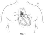
- FIG. 1 shows an illustration of a prosthetic heart valve 100 provided herein within the heart 102 of a human body 105.
- the human body 105 has four heart valves: a pulmonary valve, a tricuspid valve, an aortic valve and a mitral valve.
- the purpose of the heart valves is to allow blood to flow through the heart and from the heart into the major blood vessels connected to the heart, such as the aorta and pulmonary artery.
- aortic prosthetic heart valve that can be delivered using a transcatheter aortic valve replacement (TAVR) procedure (which is also described as percutaneous aortic valve replacement (PAVR) or transcatheter aortic valve implantation (TAVI)), which involves the use of a deployment device 110 (which can also be referred to as a delivery catheter or delivery system) placed through blood vessels from a femoral, subclavian, or direct aortic incision.
- Deployment device 110 can deliver prosthetic heart valve 100 to the desired location within the anatomy, and release implantable heart valve 100 at an implantation site.
- prosthetic heart valve 100 can be another type of heart valve (e.g., a mitral valve or a tricuspid valve), in some cases.
- the prosthetic heart valve provided herein can be generally applicable to valves within the body,
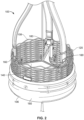
- FIG. 2 provides a close up view of the prosthetic heart valve 100 of FIG. 1 having inflow end 106 and an outlet end 108.
- Prosthetic heart valve 100 has a substantially tubular body 120, a plurality of leaflets 140, anchor elements 160 and a tubular seal 180.
- Tubular body 120 can be a radially expandable member, e.g. annular frame or stent, having an annular cavity.
- the heart valve 100 can have three heart valve leaflets 140 coupled to the tubular body 120 within the annular cavity.
- Three anchor elements 160 positioned within the annular cavity of the tubular body 120 can each secure the heart valve leaflets to the tubular body 120.
- Each anchor elements 160 can be coupled to the tubular body 120 with an anchoring element and coupled to the leaflets with a clamping element.
- the tubular seal 180 can be disposed about at least a portion of the tubular body 120.
- the tubular seal can have an inflow end portion (not shown) secured to bottom edges of the plurality of leaflets and have an outflow end portion 108 disposed about an outer surface of the tubular body 120 to restrict blood flow around the leaflets.
- Prosthetic heart valve 100 can be made of various materials. In some cases, at least a portion of the prosthetic heart valve 100, for example, the leaflets 140 or a portion of the tubular body 120, can be made of various synthetic materials. In some cases, the prosthetic heart valve 100 can be entirely made of synthetic materials.
- the synthetic materials of the prosthetic heart valve 100 can include polymeric materials, metals, ceramics, and combinations thereof. In some cases, synthetic materials of the prosthetic heart valve 100 can include a composite material composed of at least two constituent materials with different physical and/or chemical properties. By incorporating different materials with different properties into a leaflet composite material, the physical, chemical and/or mechanical properties of the composite material can be tailored, as desired.
- prosthetic heart valve 100 is implanted (e.g., surgically or through transcatheter delivery) in a mammalian heart.
- the edge portions of the polymeric leaflets 140 move into coaptation with one another in a closed position to substantially restrict fluid from flowing past prosthetic heart valve 100 in a closed position.
- the edge portions of the leaflets 140 move away from one another to an open position permitting fluid to flow past prosthetic heart valve 100. Movement of the leaflets between the closed and open positions can substantially approximate the hemodynamic performance of a healthy natural valve.
- the leaflet 140 can be partially made from tissue obtained from an animal, e.g., a pig or a cow. In some cases, for example, a portion of the leaflet 140 can be made from bovine pericardium or porcine tissue.
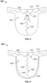
- FIGS. 3A and 3B show leaflets 300 of an exemplary prosthetic heart valve discussed herein during various time periods of a cardiac cycle.
- FIG. 3A shows prosthetic heart valve during diastole
- FIG. 3B shows prosthetic heart valve during systole.
- Diastole is the time period of a cardiac cycle at which a heart chamber fills with blood and the surrounding heart muscles are relaxed.
- Ventricular diastole is the period at which the ventricles are filling with blood and the ventricular walls are in a relaxed state
- atrial diastole is the period at which the atriums are filling with blood and the atrial walls are relaxed.
- Systole is the time period of a cardiac cycle at which blood in the heart chamber empties and the heart chamber muscles are in a contracted state due to a response to an electrochemical stimulus.
- Leaflets 300 are strained in different locations and with different intensities during various periods of the cardiac cycle. As shown in FIG. 3A , three polymeric leaflets 300 of a prosthetic heart valve are at a closed state during diastole. The three leaflets 300 form a commissure when the valve is in a close state. As shown, the strain curves "a" of the leaflets 300 extend in an arc-shaped profile near a commissure.
- prosthetic heart valve is shown with three polymeric leaflets 300 at an open state during systole.
- the open end of the leaflets 300 separate as blood is allowed to pass through the valve.
- strain curves "b" of the leaflets during systole can extend along a chord length defined by the two points where each leaflet 300 connects to an adjacent leaflet and the tubular body.
- FIG. 4 shows an example of a prosthetic heart valve leaflet 400 provided herein.
- leaflet 400 can include a body portion 410 (or belly region of the leaflet) and two sleeve portions 420 that extend outwardly from the body portion 410.
- the body portion 410 has a bottom edge 430, a first side edge 440, a second side edge 450, and a free edge 460.
- Leaflet 400 further includes a front side (i.e., the side that blood flows toward), a back side (i.e., the side that blood flows away from).
- the bottom and side edges 410, 430 of the body portion 410 can be shaped for suturing and for forming a leaflet profile similar to a native valve.
- the sleeve portions 420 can be shaped to be compatible with anchor elements, such as anchor elements 160 of FIG. 2 .
- each leaflet flexes between an open and a closed position. Tensile and flexural strain on each leaflet can change depending on its position.
- the leaflet 400 can elongate in various directions as the valve opens and closes. For instance, leaflet 400 can elongate in a radial direction D R and a circumferential direction D C along the body portion 410 and/or the sleeve portions 420.
- the radial direction D R of a leaflet in a heart valve can extend radially inwardly or outwardly, e.g., a radial direction can extend from the center of the heart valve along a commissure line to a tubular body.
- the circumferential direction D C can extend along a circumference of a heart valve, e.g., an inner circumference of the tubular body 120 of FIG. 2 .
- the radial direction D R extends from the free edge 460 to the bottom edge 430 of the leaflet.
- a circumferential direction D C extends in a direction that is generally orthogonal to the radial direction D R . More specifically, the circumferential direction D C extends from one side edge to the opposite side edge of the sleeve portion.
- the circumferential direction D C can also extend from one side of the body portion (e.g., the first side edge 440 ) to an opposite side of the body portion (e.g., the second side edge 450 ), which can be described as a circumferential direction D c in the belly region of the leaflet 400.
- the leaflet 400 can elongate in a direction having an angle that is oblique relative to the radial and circumferential directions.
- FIG. 5 shows an exemplary prosthetic heart tissue valve leaflet 500 having a composite material that includes a plurality of fibers 505 embedded in a polymer matrix 502.
- each fiber 505 has an extending direction (which can also be described as an orientation) and includes a plurality of undulations 515.
- each undulation defines a crest that is orthogonal or oblique to the extending direction.
- a fiber shape 505 of the fibers 505 provided herein can be described as a repeating wave or curve pattern within the polymer matrix 502.
- the fibers 505 can be described as having a sinusoidal configuration and/or a plurality of orientations.
- the plurality of undulations and other non-linear configurations provide the composite material with multi-stage elasticity properties discussed herein.
- each fiber has a plurality of undulations, in which each undulation 515 has an amplitude "A" and a wavelength " ⁇ .”
- the plurality of undulations of each fiber 505 thus has an average amplitude and an average wavelength.
- the amplitude or the average amplitude of a plurality of undulations can range from 0.1 mm (or 100 microns) to 5 mm.
- the amplitude or the average amplitude of a plurality of undulations can range from 0.5 mm to 2 mm.
- the wavelength or the average wavelength of a plurality of undulations can range from 0.1 mm to 3 mm.
- the wavelength or the average wavelength of a plurality of undulations can range from 0.2 mm to 2 mm.
- Each fiber 505 can be defined by a total fiber length and a segment distance.
- the total fiber length is the length of the fiber if its undulations were straightened out and the fiber was straight when measured.
- the segment distance is the distance between where the fiber 505 starts to the where the fiber ends.
- Elasticity properties of the composite material can be adjusted, as desired, by modifying the amplitude and wavelength of the undulations.
- Fibers 505 having a plurality of undulations can provide a benefit of producing a composite material with multi-stage elastic properties.
- the composite material has multistage elastic properties when the elasticity characteristics are influenced by two or more materials.
- the composite material can exhibit an initial elastic characteristic and a subsequent elastic characteristic.
- the bending stiffness of the undulations in the fibers and the material properties of the polymer matrix 502 contribute to the initial elastic characteristic of the composite material when first stretched.
- the polymer matrix 502 that surrounds each fiber 505 stretches and the undulations of individual fiber can become straightened.
- the composite material Eventually after one or more fibers 505 become straight, the composite material exhibits the subsequent elastic characteristic because the fibers 505 begin to significantly reduce the elasticity and increase the tensile strength of the composite material.
- the composite material is therefore more elastic when the plurality of fibers 505 include a plurality of undulations and less elastic when at least some of the plurality of fibers 505 have become stretched into a substantially straight fibers.
- the composite material can exhibit an elasticity similar to the polymer matrix when the plurality of fibers 505 include a plurality of undulations and an elasticity similar to the fiber material once the fibers 505 have become straight.
- the elasticity of the composite material can become significantly reduced when the total fiber length of at least a portion of its fibers 505 is about equal to or greater than the segment distance, i.e., the distance between where the fiber starts and ends.
- the composite material can have a first elasticity when an average fiber length is less than an average fiber segment distance and a second elasticity when the average fiber length is about equal to or greater than the average fiber segment distance.
- At least a portion of the plurality of fibers 502 extends in a circumferential direction provided herein and at least a portion of the plurality of fibers 505 extends in a radial direction provided herein on leaflet 500.
- circumferentially-directed fibers 525 extend from one side edge to the opposite side edge of a sleeve portion and radially-directed fibers 535 extend from a free edge to a bottom edge of the leaflet 500.
- a majority of the fibers 505 extend in the circumferential direction or the radial direction.
- the ratio of fibers 505 extending in the circumferential direction to the radial direction can be about 1:1.
- the ratio of fibers 505 that extend from the circumferential direction to the radial direction can range from 1:10 to 1:5, from 1:5 to 1:4, from 1:4 to 1:3, form 1:3 to 1:2, from 1:2 to 1:1, from 1:1 to 2:1, from 2:1 to 3:1, from 3:1 to 4:1, from 4:1 to 5:1, from 5:1 to 10:1, from 1:10 to 10:1, from 1:5 to 5:1, from 1:4 to 4:1, from 1:3 to 3:1, from 1:2 to 2:1, from 1:10 to 5:1, from 1:10 to 4:1, 1:10 to 3:1, from 1:10 to 2:1, from 1:10 to 1:1, from 1:1 to 1:10, from 1:2 to 1:10, from 1:3 to 1:10, from 1:4 to 1:10, from 1:5 to 1:10, from 1:6 to 1:10, from 1:7 to 1:10, from 1:8 to 1:10, or from 1:9 to 1:10.
- the ratio of fibers 505 extending in the circumferential direction to the radial direction can provide the composite material with anisotropic
- the composite material of leaflet 500 includes a polymer matrix 502 with multiple pluralities of fibers 505.
- composite materials include a first plurality of fibers 505 and a second plurality of fibers 505 both embedded in the polymer matrix 502, for example.
- Fibers 505 of the first plurality of fibers have a first extending direction and a plurality of undulations.
- Fibers 505 of a second plurality of fibers have a second extending direction and a plurality of undulations.
- the plurality of undulations can be described as transversal waves that have crests that are orthogonal or oblique to the first extending direction.
- the first extending direction can be different from the second extending direction.
- the first and second directions can define first and second longitudinal axes, respectively.
- the first longitudinal axis is orthogonal to the second longitudinal axis.
- the first longitudinal axis is oblique to the second longitudinal axis.
- the extending direction(s) of fibers of a composite material can provide isotropic properties because the composite material will be more elastic in a direction parallel to the extending direction and less elastic in a direction orthogonal or oblique to the extending direction.
- Fibers 505 of the leaflets 500 provided herein can be made of various materials.
- fibers 505 can be made of a medically suitable fiber material.
- Suitable fiber materials that use polymers can include, but are not limited to, polypropylenes, polyesters, polytetrafluoroethylenes (PTFE) such as TEFLON ® by E.I. DuPont de Nemours & Co., polyethylenes, polyurethanes, polyamides, nylons, polyetheretherketones (PEEK), polysulfones, fiberglass, acrylics, tantalum, polyvinyl alcohols, carbon, ceramics, metals (e.g., titanium, stainless steel), and combinations thereof.
- PTFE polytetrafluoroethylenes
- PEEK polyetheretherketones
- fiberglass acrylics, tantalum, polyvinyl alcohols, carbon, ceramics, metals (e.g., titanium, stainless steel), and combinations thereof.
- suitable polymers for forming fibers 505 made from polyurethanes for example, polyurethane elastomers (e.g. Pellethane), polyether-based polyurethanes (e.g. Tecothane), polycarbonate-based polyurethanes (e.g. Bionate and/or Chronoflex) and combinations thereof.
- suitable polymer materials for fibers 505 include, but are not limited to, polycarbonate, polyether, polyester, polyamide, nylon 6, nylon 12, polyetherimide and combinations thereof.
- fibers 505 can be made of a silk-based biomaterial.
- Silk-based biomaterials can include materials constructed from silk proteins such as silkworm fibroin, spider fibroin or Bombyx mori silk fibroin.
- fibers 505 can be composed of silk-like materials such as fibronectin, elastin, or other silk-like proteins, for example, aneroin which is a protein derived from the sea anemone Nematostella vectensis.
- fibers 505 within the composite material of a leaflet 500 provided herein can be made of a liquid crystalline polymer (LCP).
- LCPs are a special class of aromatic polyester and/or polyamide copolymers that have semi-crystalline properties due to regions of highly ordered crystalline structures formed therein.
- Suitable fiber materials made of LCPs include, but are not limited to, thermotropic polyester such as Vectran ® , poly(p-phenylene terephthalamide) (PPTA), and poly(phenylene benzobisoxazole) (PBO) and combinations thereof.
- LCPs include Kevlar ® , Vectran ® , Nomex ® , Herachron ® , Technora ® , Twaron ® , and Zylon ® .
- high performance fibers can be utilized in composite materials, such as gel-spun ultra-high molecular weight polyethylene (Dyneema ® ).
- LCPs are generally chemically inert and have a high creep resistance, a high modulus and a high tensile strength. LCPs provide the advantage of using materials with thinner and smaller dimensions, e.g., composite layer thickness or fiber diameter, without compromising strength, robustness and durability. In some cases, the diameter of LCP fibers can be as small as 0.5 micrometers (microns), or about .00002 inches, and a total thickness of a leaflet 500 provided herein composed of LCP fibers can be as thin as about 50 microns to about 100 microns (or about .002 to about .004 inches).
- individual fibers 505 of a composite material can be encapsulated within a jacket (e.g., a polymer jacket) to promote bonding between the fibers 505 and the polymer matrix 502.
- a jacket e.g., a polymer jacket
- the leaflet 500 provided herein can include LCP fibers that have been encapsulated within a polymer jacket.
- Suitable materials for the polymer jacket include, but are not limited to, polyurethane and derivatives of polyurethane.
- the polymer jacket can be made of a polyisobutylene polyurethane copolymer.
- Leaflets 500 provided herein can include composite materials having fiber diameters that can range from about 0.5 microns to about 200 microns (or about .00002 inches to about .0079 inches). In some cases, fibers 505 can have diameters or average diameters of at least 1 micron (or .00004 inches). Fibers can be, in some cases, in the range of about 1 micron to about 100 microns (or about .00004 inches to about .004 inches), including all ranges and values therebetween.
- suitable fiber diameter sizes can include ranges of about 1 micron to 5 microns (or about .00004 inches to about .0002 inches), 5 microns to 10 microns (or .0002 inches to about .0004 inches), 10 microns to 20 microns (or .0004 inches to about .0008 inches), 20 microns to 50 microns (or .0008 inches to about .0020 inches), and 50 microns to 100 microns (or .002 inches to about .004 inches).
- fibers 505 can have diameters in the range of about 1 microns to about 10 microns (or .0004 inches to about .0020 inches), including all ranges and values therebetween.
- the fiber made from polymers can range from about 5 microns to about 100 microns (or .00002 inches to about .0040 inches), from about 10 microns to about 75 microns (or .0004 inches to about .003 inches), from about 10 micron to about 50 microns (or .0004 inches to about .0020 inches), from about 20 microns to about 100 microns (or .0008 inches to about .0040 inches), from about 25 microns to about 200 microns (or .001 inches to about .008 inches), or from about 20 microns to about 50 microns (or .0008 inches to about .002 inches).
- fibers 505, such as LCP fibers can range from 0.5 microns (or 500 nanometers) to 5 microns (or about .00002 inches to about .00020 inches).
- the polymer matrix 502 can be made of various polymeric materials. In some cases, the polymer matrix 502 can be made of an elastomeric polymer. Suitable polymer matrix materials include, but are not limited to, homopolymers, copolymers and terpolymers. Various polyurethanes can be used to construct the polymer matrix 502, such as polyurethanes with soft segments such as polyether, perfluoropolyether, polycarbonate, polyisobutylene, polysiloxane, or combinations thereof.
- Polyurethane hard segments can include, but are not limited to, methylene diphenyl diisocyanate (MDI), 4,4'-Methylene dicyclohexyl diisocyanate (H12MDI) and hexamethylene (HMDI).
- the polymer matrix 502 can be formed from block polymers such as, for example, poly(styrene-isobutylene-styrene) (SIBS) tri-block polymers.
- elastomeric materials include, but are not limited to, silicones, nitrile rubber, fluoroelastomers, polyolefin elastomers, latex-type elastomers, various natural elastomers such as those made from collagen, elastin, cellulose, proteins, carbohydrates and combinations thereof.
- a leaflet 500 provided herein includes a composite material having a polymer matrix 502 composed of polyurethanes provided herein and a plurality of fibers composed of Vectran ® , which is presently manufactured by Kuraray Co., Ltd.
- Vectran ® is a polyester-based LCD made by the polycondensation of 4-hydroxybenzoic acid and 6-hydroxynaphthalene-2-carboxylic acid.
- an outer surface of a composite material can include zwitterionic polymers to reduce the calcification propensity of one or more synthetic materials.
- a zwitterionic polymer includes a backbone with a zwitterionic group (which can also be described as a zwitterionic species or a zwitterionic compound).
- a zwitterionic group, or a zwitterion (also described as a dipolar ion or an inner salt), is a neutrally charged compound, or molecule, having both a negatively charged ion (anion) and a positively charged ion (cation).
- the zwitterionic polymer can include a zwitterionic pendant group (also described as a side group).
- the zwitterionic polymer can be formed from one or more monomers, wherein the monomer includes a zwitterionic group.
- a composite material can have a polymer coating that includes polymerized units of a monomer including a zwitterionic group when the polymer coating is exposed to an aqueous environment, in particular blood, at a PH of about 7.4.
- a zwitterionic group of a monomer can be formed by a carboxylic acid group, a sulfonic acid group, or a phosphoric acid group.
- a monomer can include a zwitterionic group composed of an acrylate, a methacrylate, an acrylamide, or a methacrylamide.
- a cation of a zwitterionic group can be formed by an (cyclo)aliphatic or aromatic amine, an amidine, or a guanidine. In some cases, a cation of a zwitterionic group can be a quaternary amine.
- a cation and an anion of a zwitterionic group can be part of the same pendant group of the monomer unit.
- the pendant group has the structure formula: X-(CH2)n-N+R2-(CH2)m-Y or X-(CH2)n-O-P(O-)-(CH2)m-Z, wherein:
- Zwitterionic polymers can generally minimize or prevent biological responses normally caused by synthetic materials implanted in a body by creating a water-saturated surface that generally inhibits protein adsorption.
- Benefits of using zwitterionic polymeric surfaces include increasing the hydrophilicity, nonspecific protein adsorption resistance and/or platelet adhesion resistance of synthetic surfacesIn some cases, the composite material can be coated with a hydrogel to increase hydrophilicity of the leaflet surface. Increasing the hydrophilicity of the leaflet surface can be desirable for the reasons discussed herein.
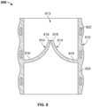
- FIG. 6 shows another exemplary leaflet 600 of a prosthetic heart tissue valve according to the present invention.
- Leaflet 600 is made of a composite material that includes a plurality of fibers 605 embedded in a polymer matrix 602. Each fiber 605 can have an extending direction and a plurality of undulations 615 orthogonal to the extending direction. As shown in FIG. 6 , at least a portion of the plurality of fibers extends in a circumferential direction, a radial direction and a direction along at least a portion of an edge profile of leaflet.
- leaflet 600 has circumferentially-directed fibers 625 that extend from one side edge to the opposite side edge of a sleeve portion and radially-directed fibers 635 that extend from a free edge to a bottom edge of the leaflet 600. Furthermore, as shown, leaflet 600 has at least one curved fiber, or a curvilinear fiber 645, that begins at one side edge of a leaflet belly region and ends at an opposite side edge, extending along a U-shape contour therebetween. In some cases, leaflet 600 can have curvilinear fibers 645 in the body portion and/or sleeve portion.
- the curvilinear fibers 645 are shaped similar to an outline edge of the leaflet 600, for example, curvilinear fibers 645 extending along the U-shape contour. In some cases, the curvilinear fibers 645 can be shaped to a form or contour to provide non-linear elasticity to a particular area of the leaflet 600.
- the curvilinear fiber 645 of leaflet 600 has a plurality of undulations 615 that vary in amplitude and wavelength.
- the amplitude and wavelength of the undulations 615 of curvilinear fiber 645 gradually increase from the side edges proximate the sleeve portions to the apex of the leaflet belly region.
- leaflet 600 can have at least one fiber 645 having a plurality of undulations 615 that vary in amplitude and/or the wavelength.
- at least one fiber 645 can have a plurality of undulations 615 in at least one portion of the fiber, and no undulations in another portion of the fiber.
- a fiber 645 of leaflet 600 can have a plurality of undulations 615 having a constant amplitude and wavelength.
- FIG. 7 provides approximated stress-strain curves of leaflets made from various materials within an elastic region of deformation. More specifically, FIG. 7 provides a comparison of mechanical properties of a thermoplastic polymer A, bioprosthetic tissue B, a composite material provided herein C, and a pure elastomer D during elastic deformation.
- the composite material C being represented in the graph is composed of a composite material provided herein having an elastomeric material and a plurality of undulating fibers.
- the stress-strain curve of FIG. 7 shows that the thermoplastic material A has a generally linear curve with a low elongation and a high yield strength as compared to the pure elastomer D that has an exponential curve having a high elongation and a low yield strength.
- the composite material C as shown, has mechanical properties that are distinguishable from the thermoplastic polymer A and the pure elastomer D. In comparison to these materials, the composite material C has a higher elongation than thermoplastic A and a higher yield strength than elastomer D.
- the composite material C of FIG. 7 can behave like these materials at certain stages of elongation, depending on the fiber configuration within the composite material. For instance, the composite material C of FIG. 7 may behave similar to an elastomer D while the plurality of undulations of the fibers are initially stretching and behave similar to a thermoplastic A once the undulations of fibers have stretched and the fibers have become straight.
- the composite material C behaves most like the bioprosthetic tissue B.
- both the bioprosthetic tissue B and composite material C are able to elongate to a comparable elongation length ( ⁇ B ⁇ ⁇ C ) in an elastic region of deformation.
- the bioprosthetic tissue B and composite material C both exhibit a high yield strength when at a higher elongation value as compared to the thermoplastic A.
- the composite material C may, however, in some cases, exhibit higher stress values than the bioprosthetic tissue B at a low elongation range due to the elastomeric characteristics of its polymer matrix.
- FIG. 7 provides an illustration of the mechanical characteristics of some embodiments of a composite material used to form tissue leaflets provided herein.
- the mechanical behavior of the composite material can, however, be modified by altering undulation characteristics of the fibers.
- Various configurations or orientations of the fibers can be applied to obtain suitable mechanical characteristics of the composite material can be modified.
- elasticity of the composite material can be modified by changing wavelength, frequency and/or amplitude of a plurality of undulations of one or more fibers.
- the elasticity of the composite material can be reduced, in some cases, by reducing the wavelengths and increasing the frequency of the fiber undulations.
- FIG. 8 provides another embodiment of an artificial heart valve 800.
- Prosthetic heart valve 800 includes a base 812 defining a substantially cylindrical passage 813 and a plurality of polymeric leaflets 814 disposed along the substantially cylindrical passage 813.
- Each polymeric leaflet 814 includes a respective root portion 816 coupled to base 812 and a respective edge portion 818 movable relative to the root portion 816 to coapt with the edge portions of the other polymeric leaflets along a coaptation region.
- the each polymeric leaflet 814 includes a plurality of fibers.
- the plurality of fibers 814 include a plurality of undulations to provide the leaflet with multi-stage elastic properties.
- Base 812 includes a frame 822 disposed in a polymer layer 824.
- the polymer layer 824 can include plurality of fibers 814 that optionally include a plurality of undulations.
- Polymer layer 824 secures respective root portions 816 of polymeric leaflets 814 to the base 812.
- Polymer layer 824 can form a substantially continuous surface with respective root portions 816 of polymeric leaflets 814. This can reduce the likelihood of stress concentrations at the junction of respective root portions 816 and base 812.
- polymer layer 824 can be disposed between each of polymeric leaflets 814 and frame 822 such that polymer layer 824 protects polymeric leaflets 814 from inadvertent contact with frame 822 (e.g., as can occur through eccentric deformation of prosthetic heart valve 800 on a calcium deposit present at the implantation site).
- frame 822 is substantially cylindrical such that the outer surface of the base 812 is substantially cylindrical and the polymer layer 824 disposed on the frame 822 forms the substantially cylindrical passage 813. In some cases, frame 822 is completely disposed in the polymer layer 824, with the polymer layer 824 forming a contoured outer surface of the valve 800. In some cases, the frame 822 is partially disposed in the polymer layer 824. In some cases, the polymer layer 824 is applied to the frame 822 to form a substantially smooth inner and/or outer surface of the valve 800.
- Methods provided herein can be used to form a medical device, such as a prosthetic heart valve leaflet provided herein, made of one or more composite materials.
- the methods provided herein can be used to form a leaflet with at least one of the composite materials provided herein having multi-stage elastic properties.
- the method of forming a leaflet includes disposing a first polymeric layer on a mandrel.
- the method of forming a leaflet includes disposing a plurality of fibers having a plurality of undulations on the first polymeric layer discussed herein.
- the method of forming a leaflet includes disposing a second polymeric layer on the plurality of fibers discussed herein.
- Various methods can be used for incorporating fibers into a polymer matrix to adequately bond fibers within a polymer matrix. Methods provided herein can be used to clean and/or surface modify fibers, encapsulate fibers in a jacket (e.g., a polymer jacket), deposit fibers into a mesh pattern of a leaflet, and coat a fibrous matrix with a polymer solution.
- a jacket e.g., a polymer jacket
- Fibers can be cleaned and/or surface modified to enhance adhesion of the fibers to another polymeric material, e.g. a polymer matrix or polymeric jacket.
- Suitable methods for cleaning and/or surface modifying fibers include, but are not limited to, atmospheric plasma treating, corona treating, acid etching and vacuum plasma treating. Cleaning and surface modification processes can be applied to fibers before or after the fibers have been configured onto a target surface.
- fibers of a leaflet can be made using solvent-based methods, such as extrusion or micro-capillary methods, as well as other methods, known to those skilled in the art.
- solvent-based methods such as extrusion or micro-capillary methods, as well as other methods, known to those skilled in the art.
- suitable methods can include, but are not limited to, electrospinning, force spinning and melt-blowing processes.
- Electrospinning is a process that uses electrical charge to create fibers from a liquid while force spinning is a process that uses centrifugal force to create fibers.
- Melt-blowing is a process in which a molten thermoplastic resin is extruded through a die and then stretched and cooled with high-velocity air to form long, fine fibers.
- fibers can be formed prior to being deposited onto a leaflet.
- preformed fibers can be deposited and oriented as desired into a mesh pattern in the shape of a valve leaflet. Fibers can be oriented to optimize mechanical property anisotropy and allow for different degrees of elongation in different directions, if desired.
- fibers can be deposited directly onto a target surface, e.g., a polymer matrix surface. Fibers can be deposited onto a target surface using methods provided herein to create a non-woven matrix or a woven fibrous matrix.
- Individual fibers of a composite material can be optionally encapsulated in a jacket (e.g., a polymer jacket) to promote bonding and reduce the risk of fibers being released from a polymer matrix.
- a jacket e.g., a polymer jacket
- individual fibers can be encapsulated in a polymer jacket with a conformal coating by using a solution process, such as spray coating or dip coating.
- fiber encapsulation can be facilitated using a reactive process to promote covalent bonding between a fiber and a polymer jacket.
- An exemplary reactive process can include coating a fiber with a primer solution of diisocyanate, such as monomers or low molecular weight oligomers of methylene diphenyl diisocyanate (MDI), curing the diisocyanate to the fiber surface, and applying over the coated fiber a reactive layer of hydroxyl terminated oligomer or amine terminated oligomers.
- a primer solution of diisocyanate such as monomers or low molecular weight oligomers of methylene diphenyl diisocyanate (MDI)
- MDI methylene diphenyl diisocyanate
- the reactive layer of hydroxyl terminated oligomer or amine terminated oligomers can be applied to a fiber without adding a diisocyanate coating.
- Fibers can be encapsulated in a jacket (e.g., a polymer jacket) before or after being deposited onto the target surface.
- a jacket e.g., a polymer jacket
- fibers can be coated with a polymer solution once formed and oriented as desired on a target surface.
- the polymer solution applied to the fibers can be a reactive or a non-reactive polymer solution. Residual solvents that might be present in the resultant polymer coated fiber can be minimized or removed by using appropriate solvents, heating, filtering and/or drying the composite material.
Landscapes
- Health & Medical Sciences (AREA)
- Engineering & Computer Science (AREA)
- Cardiology (AREA)
- Biomedical Technology (AREA)
- Veterinary Medicine (AREA)
- General Health & Medical Sciences (AREA)
- Oral & Maxillofacial Surgery (AREA)
- Transplantation (AREA)
- Public Health (AREA)
- Life Sciences & Earth Sciences (AREA)
- Animal Behavior & Ethology (AREA)
- Chemical & Material Sciences (AREA)
- Vascular Medicine (AREA)
- Heart & Thoracic Surgery (AREA)
- Dermatology (AREA)
- Medicinal Chemistry (AREA)
- Epidemiology (AREA)
- Composite Materials (AREA)
- Mechanical Engineering (AREA)
- Manufacturing & Machinery (AREA)
- Materials Engineering (AREA)
- Prostheses (AREA)
- Materials For Medical Uses (AREA)
Description
- This invention relates to prosthetic heart valves having leaflets having undulating fibers embedded in a polymer matrix.
- Heart function can be significantly impaired when a heart valve is not functioning properly. Potential causes for heart valve malfunction include dilation of an annulus around the valve, ventricular dilation, and a prolapsed or misshapen valve leaflet. When the heart valve is unable to close properly, blood within a heart chamber can leak backwards, commonly referred to as regurgitation, through the valve.
- Valve regurgitation may be treated by replacing or repairing a diseased valve, such as an aortic valve. Surgical valve replacement is one method for treating the diseased valve, but other less invasive methods of treatments are also available to many patients. Minimally invasive methods of treatment, such as transcatheter aortic valve replacement (TAVR), generally involve the use of delivery devices that are delivered through arterial passageways or other anatomical routes into the heart to replace the diseased valve with an implantable prosthetic heart valve. There is a desire to reduce the profile of the devices used for delivery and implantation to minimize trauma to blood vessels during device delivery and implantation. Though in a crimped state during device delivery, the valve leaflet of a prosthetic heart valve can still significantly contribute to the device profile. Accordingly, there is a need to reduce to the valve leaflet thickness of prosthetic heart valves.
- Document
US2014005771 andUS20145772 -
WO 2010/048281 andWO 2009/038761 describe composite materials for heart valve leaflets comprising embedded fibers having a plurality of undulations. -
WO 2014/149319 ,US 2014/0005772 ,WO 2008/097592 andWO 02/074201 - Prosthetic heart valves provided herein have a structure adapted to optimize functionality during the life of a patient and to provide anisotropic properties to synthetic leaflet materials. Prosthetic heart valves herein include leaflets that include undulating fibers embedded in a polymer matrix.
- Prosthetic valves according to the present invention are defined in claim 1. Further aspects are defined in the dependent claims 2-10. Methods of forming a prosthetic valve according to the present invention are defined in claim 11.
- The details of one or more embodiments of the devices, systems, and methods provided herein are set forth in the accompanying drawings and the description below. Other features, objects, and advantages will be apparent from the description and drawings, and from the claims.
-
-
FIG. 1 is an illustration of an exemplary prosthetic heart valve within a human anatomy. -
FIG. 2 is an enlarged view of the prosthetic heart valve ofFIG. 1 . -
FIGS. 3A and 3B are illustrations of a prosthetic heart valve provided herein that show strain curves at diastole and systole, respectively. -
FIG. 4 provides an illustration of an exemplary leaflet provided herein. -
FIGS. 5 and 6 show various fiber configurations of a composite material for an exemplary leaflet provided herein. -
FIG. 7 shows a stress-strain graph of leaflets made of various materials. -
FIG. 8 is a side view of another exemplary prosthetic heart valve provided herein. - Like reference symbols in the various drawings indicate like elements.
-
FIG. 1 shows an illustration of aprosthetic heart valve 100 provided herein within theheart 102 of ahuman body 105. Thehuman body 105 has four heart valves: a pulmonary valve, a tricuspid valve, an aortic valve and a mitral valve. The purpose of the heart valves is to allow blood to flow through the heart and from the heart into the major blood vessels connected to the heart, such as the aorta and pulmonary artery.Prosthetic heart valve 100 ofFIG. 1 is an aortic prosthetic heart valve that can be delivered using a transcatheter aortic valve replacement (TAVR) procedure (which is also described as percutaneous aortic valve replacement (PAVR) or transcatheter aortic valve implantation (TAVI)), which involves the use of a deployment device 110 (which can also be referred to as a delivery catheter or delivery system) placed through blood vessels from a femoral, subclavian, or direct aortic incision.Deployment device 110 can deliverprosthetic heart valve 100 to the desired location within the anatomy, and releaseimplantable heart valve 100 at an implantation site. AlthoughFIG. 1 shows an aortic prosthetic heart valve, it should be appreciated thatprosthetic heart valve 100 can be another type of heart valve (e.g., a mitral valve or a tricuspid valve), in some cases. In some cases, the prosthetic heart valve provided herein can be generally applicable to valves within the body, -
FIG. 2 provides a close up view of theprosthetic heart valve 100 ofFIG. 1 havinginflow end 106 and anoutlet end 108.Prosthetic heart valve 100 has a substantiallytubular body 120, a plurality ofleaflets 140,anchor elements 160 and atubular seal 180.Tubular body 120 can be a radially expandable member, e.g. annular frame or stent, having an annular cavity. As shown inFIG. 2 , theheart valve 100 can have threeheart valve leaflets 140 coupled to thetubular body 120 within the annular cavity. Threeanchor elements 160 positioned within the annular cavity of thetubular body 120 can each secure the heart valve leaflets to thetubular body 120. Eachanchor elements 160 can be coupled to thetubular body 120 with an anchoring element and coupled to the leaflets with a clamping element. Thetubular seal 180 can be disposed about at least a portion of thetubular body 120. In particular, the tubular seal can have an inflow end portion (not shown) secured to bottom edges of the plurality of leaflets and have anoutflow end portion 108 disposed about an outer surface of thetubular body 120 to restrict blood flow around the leaflets. -
Prosthetic heart valve 100 can be made of various materials. In some cases, at least a portion of theprosthetic heart valve 100, for example, theleaflets 140 or a portion of thetubular body 120, can be made of various synthetic materials. In some cases, theprosthetic heart valve 100 can be entirely made of synthetic materials. The synthetic materials of theprosthetic heart valve 100 can include polymeric materials, metals, ceramics, and combinations thereof. In some cases, synthetic materials of theprosthetic heart valve 100 can include a composite material composed of at least two constituent materials with different physical and/or chemical properties. By incorporating different materials with different properties into a leaflet composite material, the physical, chemical and/or mechanical properties of the composite material can be tailored, as desired. - In use,
prosthetic heart valve 100 is implanted (e.g., surgically or through transcatheter delivery) in a mammalian heart. The edge portions of thepolymeric leaflets 140 move into coaptation with one another in a closed position to substantially restrict fluid from flowing pastprosthetic heart valve 100 in a closed position. The edge portions of theleaflets 140 move away from one another to an open position permitting fluid to flow pastprosthetic heart valve 100. Movement of the leaflets between the closed and open positions can substantially approximate the hemodynamic performance of a healthy natural valve. - In some cases, the
leaflet 140 can be partially made from tissue obtained from an animal, e.g., a pig or a cow. In some cases, for example, a portion of theleaflet 140 can be made from bovine pericardium or porcine tissue. -
FIGS. 3A and 3B showleaflets 300 of an exemplary prosthetic heart valve discussed herein during various time periods of a cardiac cycle. In particular,FIG. 3A shows prosthetic heart valve during diastole andFIG. 3B shows prosthetic heart valve during systole. Diastole is the time period of a cardiac cycle at which a heart chamber fills with blood and the surrounding heart muscles are relaxed. Ventricular diastole is the period at which the ventricles are filling with blood and the ventricular walls are in a relaxed state, while atrial diastole is the period at which the atriums are filling with blood and the atrial walls are relaxed. Systole is the time period of a cardiac cycle at which blood in the heart chamber empties and the heart chamber muscles are in a contracted state due to a response to an electrochemical stimulus. -
Leaflets 300 are strained in different locations and with different intensities during various periods of the cardiac cycle. As shown inFIG. 3A , threepolymeric leaflets 300 of a prosthetic heart valve are at a closed state during diastole. The threeleaflets 300 form a commissure when the valve is in a close state. As shown, the strain curves "a" of theleaflets 300 extend in an arc-shaped profile near a commissure. - Referring to
FIG. 3B , prosthetic heart valve is shown with threepolymeric leaflets 300 at an open state during systole. The open end of theleaflets 300 separate as blood is allowed to pass through the valve. Unlike the strain curves a shown inFIG. 3A , strain curves "b" of the leaflets during systole can extend along a chord length defined by the two points where eachleaflet 300 connects to an adjacent leaflet and the tubular body. -
FIG. 4 shows an example of a prostheticheart valve leaflet 400 provided herein. As shown,leaflet 400 can include a body portion 410 (or belly region of the leaflet) and twosleeve portions 420 that extend outwardly from thebody portion 410. In some cases, thebody portion 410 has abottom edge 430, afirst side edge 440, asecond side edge 450, and afree edge 460. Leaflet 400 further includes a front side (i.e., the side that blood flows toward), a back side (i.e., the side that blood flows away from). The bottom and side edges 410, 430 of thebody portion 410 can be shaped for suturing and for forming a leaflet profile similar to a native valve. Thesleeve portions 420 can be shaped to be compatible with anchor elements, such asanchor elements 160 ofFIG. 2 . - As the prosthetic heart valve opens and closes, each leaflet flexes between an open and a closed position. Tensile and flexural strain on each leaflet can change depending on its position. As such, the
leaflet 400 can elongate in various directions as the valve opens and closes. For instance, leaflet 400 can elongate in a radial direction DR and a circumferential direction DC along thebody portion 410 and/or thesleeve portions 420. The radial direction DR of a leaflet in a heart valve can extend radially inwardly or outwardly, e.g., a radial direction can extend from the center of the heart valve along a commissure line to a tubular body. The circumferential direction DC can extend along a circumference of a heart valve, e.g., an inner circumference of thetubular body 120 ofFIG. 2 . As shown inFIG. 4 , the radial direction DR extends from thefree edge 460 to thebottom edge 430 of the leaflet. A circumferential direction DC extends in a direction that is generally orthogonal to the radial direction DR . More specifically, the circumferential direction DC extends from one side edge to the opposite side edge of the sleeve portion. The circumferential direction DC can also extend from one side of the body portion (e.g., the first side edge 440) to an opposite side of the body portion (e.g., the second side edge 450), which can be described as a circumferential direction Dc in the belly region of theleaflet 400. In some cases, theleaflet 400 can elongate in a direction having an angle that is oblique relative to the radial and circumferential directions. -
FIG. 5 shows an exemplary prosthetic hearttissue valve leaflet 500 having a composite material that includes a plurality offibers 505 embedded in apolymer matrix 502. As shown inFIG. 5 , eachfiber 505 has an extending direction (which can also be described as an orientation) and includes a plurality ofundulations 515. In some cases, each undulation defines a crest that is orthogonal or oblique to the extending direction. In some cases, afiber shape 505 of thefibers 505 provided herein can be described as a repeating wave or curve pattern within thepolymer matrix 502. In some cases, thefibers 505 can be described as having a sinusoidal configuration and/or a plurality of orientations. The plurality of undulations and other non-linear configurations provide the composite material with multi-stage elasticity properties discussed herein. - According to the invention, each fiber has a plurality of undulations, in which each
undulation 515 has an amplitude "A" and a wavelength "λ." The plurality of undulations of eachfiber 505 thus has an average amplitude and an average wavelength. In some cases, the amplitude or the average amplitude of a plurality of undulations can range from 0.1 mm (or 100 microns) to 5 mm. In some cases, the amplitude or the average amplitude of a plurality of undulations can range from 0.5 mm to 2 mm. In some cases, the wavelength or the average wavelength of a plurality of undulations can range from 0.1 mm to 3 mm. In some cases, the wavelength or the average wavelength of a plurality of undulations can range from 0.2 mm to 2 mm. Eachfiber 505 can be defined by a total fiber length and a segment distance. The total fiber length is the length of the fiber if its undulations were straightened out and the fiber was straight when measured. The segment distance is the distance between where thefiber 505 starts to the where the fiber ends. Elasticity properties of the composite material can be adjusted, as desired, by modifying the amplitude and wavelength of the undulations. -
Fibers 505 having a plurality of undulations can provide a benefit of producing a composite material with multi-stage elastic properties. The composite material has multistage elastic properties when the elasticity characteristics are influenced by two or more materials. For example, the composite material can exhibit an initial elastic characteristic and a subsequent elastic characteristic. The bending stiffness of the undulations in the fibers and the material properties of thepolymer matrix 502 contribute to the initial elastic characteristic of the composite material when first stretched. As the composite material continues to be stretched, thepolymer matrix 502 that surrounds eachfiber 505 stretches and the undulations of individual fiber can become straightened. Eventually after one ormore fibers 505 become straight, the composite material exhibits the subsequent elastic characteristic because thefibers 505 begin to significantly reduce the elasticity and increase the tensile strength of the composite material. The composite material is therefore more elastic when the plurality offibers 505 include a plurality of undulations and less elastic when at least some of the plurality offibers 505 have become stretched into a substantially straight fibers. The composite material can exhibit an elasticity similar to the polymer matrix when the plurality offibers 505 include a plurality of undulations and an elasticity similar to the fiber material once thefibers 505 have become straight. In some cases, the elasticity of the composite material can become significantly reduced when the total fiber length of at least a portion of itsfibers 505 is about equal to or greater than the segment distance, i.e., the distance between where the fiber starts and ends. In some cases, for example, the composite material can have a first elasticity when an average fiber length is less than an average fiber segment distance and a second elasticity when the average fiber length is about equal to or greater than the average fiber segment distance. - Still referring to
FIG. 5 , at least a portion of the plurality offibers 502 extends in a circumferential direction provided herein and at least a portion of the plurality offibers 505 extends in a radial direction provided herein onleaflet 500. As shown, circumferentially-directedfibers 525 extend from one side edge to the opposite side edge of a sleeve portion and radially-directedfibers 535 extend from a free edge to a bottom edge of theleaflet 500. In some cases, a majority of thefibers 505 extend in the circumferential direction or the radial direction. In some cases, the ratio offibers 505 extending in the circumferential direction to the radial direction can be about 1:1. In some cases, the ratio of fibers 505 that extend from the circumferential direction to the radial direction can range from 1:10 to 1:5, from 1:5 to 1:4, from 1:4 to 1:3, form 1:3 to 1:2, from 1:2 to 1:1, from 1:1 to 2:1, from 2:1 to 3:1, from 3:1 to 4:1, from 4:1 to 5:1, from 5:1 to 10:1, from 1:10 to 10:1, from 1:5 to 5:1, from 1:4 to 4:1, from 1:3 to 3:1, from 1:2 to 2:1, from 1:10 to 5:1, from 1:10 to 4:1, 1:10 to 3:1, from 1:10 to 2:1, from 1:10 to 1:1, from 1:1 to 1:10, from 1:2 to 1:10, from 1:3 to 1:10, from 1:4 to 1:10, from 1:5 to 1:10, from 1:6 to 1:10, from 1:7 to 1:10, from 1:8 to 1:10, or from 1:9 to 1:10. The ratio offibers 505 extending in the circumferential direction to the radial direction can provide the composite material with anisotropic or isotropic properties, as desired. - The composite material of
leaflet 500 includes apolymer matrix 502 with multiple pluralities offibers 505. In some embodiments, composite materials include a first plurality offibers 505 and a second plurality offibers 505 both embedded in thepolymer matrix 502, for example.Fibers 505 of the first plurality of fibers have a first extending direction and a plurality of undulations.Fibers 505 of a second plurality of fibers have a second extending direction and a plurality of undulations. In some cases, the plurality of undulations can be described as transversal waves that have crests that are orthogonal or oblique to the first extending direction. In various cases, the first extending direction can be different from the second extending direction. In some cases, the first and second directions can define first and second longitudinal axes, respectively. In some cases, the first longitudinal axis is orthogonal to the second longitudinal axis. In some cases, the first longitudinal axis is oblique to the second longitudinal axis. The extending direction(s) of fibers of a composite material can provide isotropic properties because the composite material will be more elastic in a direction parallel to the extending direction and less elastic in a direction orthogonal or oblique to the extending direction. -
Fibers 505 of theleaflets 500 provided herein can be made of various materials. In various cases,fibers 505 can be made of a medically suitable fiber material. Suitable fiber materials that use polymers can include, but are not limited to, polypropylenes, polyesters, polytetrafluoroethylenes (PTFE) such as TEFLON® by E.I. DuPont de Nemours & Co., polyethylenes, polyurethanes, polyamides, nylons, polyetheretherketones (PEEK), polysulfones, fiberglass, acrylics, tantalum, polyvinyl alcohols, carbon, ceramics, metals (e.g., titanium, stainless steel), and combinations thereof. In some cases, suitable polymers for formingfibers 505 made from polyurethanes, for example, polyurethane elastomers (e.g. Pellethane), polyether-based polyurethanes (e.g. Tecothane), polycarbonate-based polyurethanes (e.g. Bionate and/or Chronoflex) and combinations thereof. Some examples of suitable polymer materials forfibers 505 include, but are not limited to, polycarbonate, polyether, polyester, polyamide, nylon 6, nylon 12, polyetherimide and combinations thereof. In some cases,fibers 505 can be made of a silk-based biomaterial. Silk-based biomaterials can include materials constructed from silk proteins such as silkworm fibroin, spider fibroin or Bombyx mori silk fibroin. In some cases,fibers 505 can be composed of silk-like materials such as fibronectin, elastin, or other silk-like proteins, for example, aneroin which is a protein derived from the sea anemone Nematostella vectensis. - In some cases,
fibers 505 within the composite material of aleaflet 500 provided herein can be made of a liquid crystalline polymer (LCP). LCPs are a special class of aromatic polyester and/or polyamide copolymers that have semi-crystalline properties due to regions of highly ordered crystalline structures formed therein. Suitable fiber materials made of LCPs include, but are not limited to, thermotropic polyester such as Vectran®, poly(p-phenylene terephthalamide) (PPTA), and poly(phenylene benzobisoxazole) (PBO) and combinations thereof. Well-known LCPs include Kevlar®, Vectran®, Nomex®, Herachron®, Technora®, Twaron®, and Zylon®. In some cases, high performance fibers can be utilized in composite materials, such as gel-spun ultra-high molecular weight polyethylene (Dyneema®). - LCPs are generally chemically inert and have a high creep resistance, a high modulus and a high tensile strength. LCPs provide the advantage of using materials with thinner and smaller dimensions, e.g., composite layer thickness or fiber diameter, without compromising strength, robustness and durability. In some cases, the diameter of LCP fibers can be as small as 0.5 micrometers (microns), or about .00002 inches, and a total thickness of a
leaflet 500 provided herein composed of LCP fibers can be as thin as about 50 microns to about 100 microns (or about .002 to about .004 inches). - In some cases,
individual fibers 505 of a composite material can be encapsulated within a jacket (e.g., a polymer jacket) to promote bonding between thefibers 505 and thepolymer matrix 502. In some cases, for example, theleaflet 500 provided herein can include LCP fibers that have been encapsulated within a polymer jacket. Suitable materials for the polymer jacket include, but are not limited to, polyurethane and derivatives of polyurethane. In some cases, the polymer jacket can be made of a polyisobutylene polyurethane copolymer. -
Leaflets 500 provided herein can include composite materials having fiber diameters that can range from about 0.5 microns to about 200 microns (or about .00002 inches to about .0079 inches). In some cases,fibers 505 can have diameters or average diameters of at least 1 micron (or .00004 inches). Fibers can be, in some cases, in the range of about 1 micron to about 100 microns (or about .00004 inches to about .004 inches), including all ranges and values therebetween. In some cases, for example, suitable fiber diameter sizes can include ranges of about 1 micron to 5 microns (or about .00004 inches to about .0002 inches), 5 microns to 10 microns (or .0002 inches to about .0004 inches), 10 microns to 20 microns (or .0004 inches to about .0008 inches), 20 microns to 50 microns (or .0008 inches to about .0020 inches), and 50 microns to 100 microns (or .002 inches to about .004 inches). In some cases,fibers 505 can have diameters in the range of about 1 microns to about 10 microns (or .0004 inches to about .0020 inches), including all ranges and values therebetween. In some cases, the fiber made from polymers can range from about 5 microns to about 100 microns (or .00002 inches to about .0040 inches), from about 10 microns to about 75 microns (or .0004 inches to about .003 inches), from about 10 micron to about 50 microns (or .0004 inches to about .0020 inches), from about 20 microns to about 100 microns (or .0008 inches to about .0040 inches), from about 25 microns to about 200 microns (or .001 inches to about .008 inches), or from about 20 microns to about 50 microns (or .0008 inches to about .002 inches). In some cases,fibers 505, such as LCP fibers, can range from 0.5 microns (or 500 nanometers) to 5 microns (or about .00002 inches to about .00020 inches). - The
polymer matrix 502 can be made of various polymeric materials. In some cases, thepolymer matrix 502 can be made of an elastomeric polymer. Suitable polymer matrix materials include, but are not limited to, homopolymers, copolymers and terpolymers. Various polyurethanes can be used to construct thepolymer matrix 502, such as polyurethanes with soft segments such as polyether, perfluoropolyether, polycarbonate, polyisobutylene, polysiloxane, or combinations thereof. Polyurethane hard segments can include, but are not limited to, methylene diphenyl diisocyanate (MDI), 4,4'-Methylene dicyclohexyl diisocyanate (H12MDI) and hexamethylene (HMDI). In some embodiments, thepolymer matrix 502 can be formed from block polymers such as, for example, poly(styrene-isobutylene-styrene) (SIBS) tri-block polymers. Some suitable elastomeric materials include, but are not limited to, silicones, nitrile rubber, fluoroelastomers, polyolefin elastomers, latex-type elastomers, various natural elastomers such as those made from collagen, elastin, cellulose, proteins, carbohydrates and combinations thereof. - In some cases, for example, a
leaflet 500 provided herein includes a composite material having apolymer matrix 502 composed of polyurethanes provided herein and a plurality of fibers composed of Vectran®, which is presently manufactured by Kuraray Co., Ltd. Vectran® is a polyester-based LCD made by the polycondensation of 4-hydroxybenzoic acid and 6-hydroxynaphthalene-2-carboxylic acid. - In some cases, an outer surface of a composite material can include zwitterionic polymers to reduce the calcification propensity of one or more synthetic materials. In some cases, a zwitterionic polymer includes a backbone with a zwitterionic group (which can also be described as a zwitterionic species or a zwitterionic compound). A zwitterionic group, or a zwitterion (also described as a dipolar ion or an inner salt), is a neutrally charged compound, or molecule, having both a negatively charged ion (anion) and a positively charged ion (cation). In some cases, the zwitterionic polymer can include a zwitterionic pendant group (also described as a side group). In some cases, the zwitterionic polymer can be formed from one or more monomers, wherein the monomer includes a zwitterionic group.
- In some cases, a composite material can have a polymer coating that includes polymerized units of a monomer including a zwitterionic group when the polymer coating is exposed to an aqueous environment, in particular blood, at a PH of about 7.4. In some cases, a zwitterionic group of a monomer can be formed by a carboxylic acid group, a sulfonic acid group, or a phosphoric acid group. In some cases, a monomer can include a zwitterionic group composed of an acrylate, a methacrylate, an acrylamide, or a methacrylamide. In some cases, a cation of a zwitterionic group can be formed by an (cyclo)aliphatic or aromatic amine, an amidine, or a guanidine. In some cases, a cation of a zwitterionic group can be a quaternary amine.
- In some cases, a cation and an anion of a zwitterionic group can be part of the same pendant group of the monomer unit. In some cases, the pendant group has the structure formula: X-(CH2)n-N+R2-(CH2)m-Y or X-(CH2)n-O-P(O-)-(CH2)m-Z, wherein:
- X is the point of covalent attachment to the repeat unit of the monomer;
- each R is independently selected from C1-to C4-alkyl, in particular methyl;
- n and m are each integers between 1 and 8;
- Y is a anionic group selected from COO-, SOS-, O-SO3-, O-PO3-, and PO3-; and
- Z is a cationic group derived from a (cyclo)aliphatic or aromatic amine, an amidine, a guanidine, or a quaternary amine, in particular NR'3+, wherein each R' is independently selected from C1-to C4-alkyl, in particular methyl.
- Zwitterionic polymers can generally minimize or prevent biological responses normally caused by synthetic materials implanted in a body by creating a water-saturated surface that generally inhibits protein adsorption. Benefits of using zwitterionic polymeric surfaces include increasing the hydrophilicity, nonspecific protein adsorption resistance and/or platelet adhesion resistance of synthetic surfacesIn some cases, the composite material can be coated with a hydrogel to increase hydrophilicity of the leaflet surface. Increasing the hydrophilicity of the leaflet surface can be desirable for the reasons discussed herein.
-
FIG. 6 shows anotherexemplary leaflet 600 of a prosthetic heart tissue valve according to the present invention.Leaflet 600 is made of a composite material that includes a plurality offibers 605 embedded in apolymer matrix 602. Eachfiber 605 can have an extending direction and a plurality ofundulations 615 orthogonal to the extending direction. As shown inFIG. 6 , at least a portion of the plurality of fibers extends in a circumferential direction, a radial direction and a direction along at least a portion of an edge profile of leaflet. Leaflet 600 ofFIG. 6 has circumferentially-directedfibers 625 that extend from one side edge to the opposite side edge of a sleeve portion and radially-directedfibers 635 that extend from a free edge to a bottom edge of theleaflet 600. Furthermore, as shown,leaflet 600 has at least one curved fiber, or acurvilinear fiber 645, that begins at one side edge of a leaflet belly region and ends at an opposite side edge, extending along a U-shape contour therebetween. In some cases,leaflet 600 can havecurvilinear fibers 645 in the body portion and/or sleeve portion. In some cases, thecurvilinear fibers 645 are shaped similar to an outline edge of theleaflet 600, for example,curvilinear fibers 645 extending along the U-shape contour. In some cases, thecurvilinear fibers 645 can be shaped to a form or contour to provide non-linear elasticity to a particular area of theleaflet 600. - Still referring to
FIG. 6 , thecurvilinear fiber 645 ofleaflet 600 has a plurality ofundulations 615 that vary in amplitude and wavelength. In particular, as shown inFIG. 6 , the amplitude and wavelength of theundulations 615 ofcurvilinear fiber 645 gradually increase from the side edges proximate the sleeve portions to the apex of the leaflet belly region. In some cases,leaflet 600 can have at least onefiber 645 having a plurality ofundulations 615 that vary in amplitude and/or the wavelength. In some cases, at least onefiber 645 can have a plurality ofundulations 615 in at least one portion of the fiber, and no undulations in another portion of the fiber. In some cases, afiber 645 ofleaflet 600 can have a plurality ofundulations 615 having a constant amplitude and wavelength. -
FIG. 7 provides approximated stress-strain curves of leaflets made from various materials within an elastic region of deformation. More specifically,FIG. 7 provides a comparison of mechanical properties of a thermoplastic polymer A, bioprosthetic tissue B, a composite material provided herein C, and a pure elastomer D during elastic deformation. The composite material C being represented in the graph is composed of a composite material provided herein having an elastomeric material and a plurality of undulating fibers. - The stress-strain curve of
FIG. 7 shows that the thermoplastic material A has a generally linear curve with a low elongation and a high yield strength as compared to the pure elastomer D that has an exponential curve having a high elongation and a low yield strength. The composite material C, as shown, has mechanical properties that are distinguishable from the thermoplastic polymer A and the pure elastomer D. In comparison to these materials, the composite material C has a higher elongation than thermoplastic A and a higher yield strength than elastomer D. However, the composite material C ofFIG. 7 can behave like these materials at certain stages of elongation, depending on the fiber configuration within the composite material. For instance, the composite material C ofFIG. 7 may behave similar to an elastomer D while the plurality of undulations of the fibers are initially stretching and behave similar to a thermoplastic A once the undulations of fibers have stretched and the fibers have become straight. - Still referring to
FIG. 7 , the composite material C, as a whole, behaves most like the bioprosthetic tissue B. As shown, both the bioprosthetic tissue B and composite material C are able to elongate to a comparable elongation length (εB ~ εC) in an elastic region of deformation. Also, the bioprosthetic tissue B and composite material C both exhibit a high yield strength when at a higher elongation value as compared to the thermoplastic A. The composite material C may, however, in some cases, exhibit higher stress values than the bioprosthetic tissue B at a low elongation range due to the elastomeric characteristics of its polymer matrix. -
FIG. 7 provides an illustration of the mechanical characteristics of some embodiments of a composite material used to form tissue leaflets provided herein. The mechanical behavior of the composite material can, however, be modified by altering undulation characteristics of the fibers. Various configurations or orientations of the fibers can be applied to obtain suitable mechanical characteristics of the composite material can be modified. In some cases, elasticity of the composite material can be modified by changing wavelength, frequency and/or amplitude of a plurality of undulations of one or more fibers. For example, the elasticity of the composite material can be reduced, in some cases, by reducing the wavelengths and increasing the frequency of the fiber undulations. -
FIG. 8 provides another embodiment of anartificial heart valve 800.Prosthetic heart valve 800 includes a base 812 defining a substantiallycylindrical passage 813 and a plurality ofpolymeric leaflets 814 disposed along the substantiallycylindrical passage 813. Eachpolymeric leaflet 814 includes arespective root portion 816 coupled tobase 812 and arespective edge portion 818 movable relative to theroot portion 816 to coapt with the edge portions of the other polymeric leaflets along a coaptation region. In some cases, the eachpolymeric leaflet 814 includes a plurality of fibers. In some cases, the plurality offibers 814 include a plurality of undulations to provide the leaflet with multi-stage elastic properties. -
Base 812 includes aframe 822 disposed in apolymer layer 824. Thepolymer layer 824 can include plurality offibers 814 that optionally include a plurality of undulations.Polymer layer 824 securesrespective root portions 816 ofpolymeric leaflets 814 to thebase 812.Polymer layer 824 can form a substantially continuous surface withrespective root portions 816 ofpolymeric leaflets 814. This can reduce the likelihood of stress concentrations at the junction ofrespective root portions 816 andbase 812. Additionally or alternatively,polymer layer 824 can be disposed between each ofpolymeric leaflets 814 andframe 822 such thatpolymer layer 824 protectspolymeric leaflets 814 from inadvertent contact with frame 822 (e.g., as can occur through eccentric deformation ofprosthetic heart valve 800 on a calcium deposit present at the implantation site). - In some cases,
frame 822 is substantially cylindrical such that the outer surface of thebase 812 is substantially cylindrical and thepolymer layer 824 disposed on theframe 822 forms the substantiallycylindrical passage 813. In some cases,frame 822 is completely disposed in thepolymer layer 824, with thepolymer layer 824 forming a contoured outer surface of thevalve 800. In some cases, theframe 822 is partially disposed in thepolymer layer 824. In some cases, thepolymer layer 824 is applied to theframe 822 to form a substantially smooth inner and/or outer surface of thevalve 800. - Methods provided herein can be used to form a medical device, such as a prosthetic heart valve leaflet provided herein, made of one or more composite materials. In particular, the methods provided herein can be used to form a leaflet with at least one of the composite materials provided herein having multi-stage elastic properties. In some cases, the method of forming a leaflet includes disposing a first polymeric layer on a mandrel. In some cases, the method of forming a leaflet includes disposing a plurality of fibers having a plurality of undulations on the first polymeric layer discussed herein. In some cases, the method of forming a leaflet includes disposing a second polymeric layer on the plurality of fibers discussed herein.
- Various methods can be used for incorporating fibers into a polymer matrix to adequately bond fibers within a polymer matrix. Methods provided herein can be used to clean and/or surface modify fibers, encapsulate fibers in a jacket (e.g., a polymer jacket), deposit fibers into a mesh pattern of a leaflet, and coat a fibrous matrix with a polymer solution.
- Fibers can be cleaned and/or surface modified to enhance adhesion of the fibers to another polymeric material, e.g. a polymer matrix or polymeric jacket. Suitable methods for cleaning and/or surface modifying fibers include, but are not limited to, atmospheric plasma treating, corona treating, acid etching and vacuum plasma treating. Cleaning and surface modification processes can be applied to fibers before or after the fibers have been configured onto a target surface.
- Various methods can be employed to form fibers of a leaflet that are well known to those skilled in the art. In some cases, fibers can be made using solvent-based methods, such as extrusion or micro-capillary methods, as well as other methods, known to those skilled in the art. Examples of some suitable methods can include, but are not limited to, electrospinning, force spinning and melt-blowing processes. Electrospinning is a process that uses electrical charge to create fibers from a liquid while force spinning is a process that uses centrifugal force to create fibers. Melt-blowing is a process in which a molten thermoplastic resin is extruded through a die and then stretched and cooled with high-velocity air to form long, fine fibers.
- In some cases, fibers can be formed prior to being deposited onto a leaflet. In particular, preformed fibers can be deposited and oriented as desired into a mesh pattern in the shape of a valve leaflet. Fibers can be oriented to optimize mechanical property anisotropy and allow for different degrees of elongation in different directions, if desired. In some cases, fibers can be deposited directly onto a target surface, e.g., a polymer matrix surface. Fibers can be deposited onto a target surface using methods provided herein to create a non-woven matrix or a woven fibrous matrix.
- Individual fibers of a composite material can be optionally encapsulated in a jacket (e.g., a polymer jacket) to promote bonding and reduce the risk of fibers being released from a polymer matrix. In some cases, individual fibers can be encapsulated in a polymer jacket with a conformal coating by using a solution process, such as spray coating or dip coating. In some cases, fiber encapsulation can be facilitated using a reactive process to promote covalent bonding between a fiber and a polymer jacket. An exemplary reactive process can include coating a fiber with a primer solution of diisocyanate, such as monomers or low molecular weight oligomers of methylene diphenyl diisocyanate (MDI), curing the diisocyanate to the fiber surface, and applying over the coated fiber a reactive layer of hydroxyl terminated oligomer or amine terminated oligomers. In some cases, the reactive layer of hydroxyl terminated oligomer or amine terminated oligomers can be applied to a fiber without adding a diisocyanate coating.
- Fibers can be encapsulated in a jacket (e.g., a polymer jacket) before or after being deposited onto the target surface. In the latter case, fibers can be coated with a polymer solution once formed and oriented as desired on a target surface. The polymer solution applied to the fibers can be a reactive or a non-reactive polymer solution. Residual solvents that might be present in the resultant polymer coated fiber can be minimized or removed by using appropriate solvents, heating, filtering and/or drying the composite material.
- A number of embodiments of devices, systems, and methods have been provided herein. Nevertheless, it will be understood that various modifications may be made without departing from the scope of the subject matter provided herein. Accordingly, other embodiments are within the scope of the following claims.
Claims (11)
- A prosthetic heart valve comprising a composite material comprised in a leaflet (140; 400; 600) comprising fibers (605) embedded in a polymer matrix (602), wherein the leaflet (140; 400; 600) comprises a belly region (410) having a bottom edge (430), a first side edge (440), a second side edge (450), and a free edge (460), the leaflet further comprising two sleeve portions (420) that extend outwardly from the belly portion (410), wherein the fibers include radially-directed fibers (635) that extend from the free edge to the bottom edge and at least one curvilinear fiber (645) that begins at one side edge of the leaflet belly region and ends at an opposite side edge extending along a U-shape contour therebetween,
characterized in that the fibers further include circumferentially-directed fibers (625) that extend from one side edge to the opposite side edge of the sleeve portions and in that each of the fibers (605) has a plurality of undulations (615). . - The prosthetic heart valve of claim 1, wherein the plurality of undulations of each fiber is adapted to straighten when the composite material is stretched in the first extending direction of the fibers.
- The prosthetic heart valve of one of claims 1-2, wherein the composite material is more elastic in a direction parallel to the first extending direction and less elastic a direction oblique to the first extending direction.
- The prosthetic heart valve of one of claims 1-3, wherein the composite material has a first elasticity when an average segment distance of the plurality of fibers is less than an average total fiber length of the plurality of fibers and a second elasticity when the average segment distance of the plurality of fibers is equal to or greater than the average total fiber length of the plurality of fibers, wherein the first elasticity is greater than the second elasticity.
- The prosthetic heart valve of one of claims 1-4, wherein the undulations have a predetermined average amplitude ranging between 0.5 mm and 2 mm and a predetermined average wavelength ranging between 0.5 mm to 2 mm.
- The prosthetic heart valve of one of claims 1-5, wherein the plurality of fibers comprise a thermoplastic polymer.
- The prosthetic heart valve of one of claims 1-6, wherein the plurality of fibers comprise a liquid crystalline polymer.
- The prosthetic heart valve of one of claims 1-7, wherein the polymer matrix comprises an elastomeric polymer.
- The prosthetic heart valve of claim 1, wherein the at least one curvilinear fiber has a plurality of undulations that vary in amplitude and wavelength, wherein the amplitude and wavelength of the undulations of the curvilinear fiber gradually increase from the side edges proximate the sleeve portions to the apex of the leaflet belly region.
- The prosthetic heart valve of claim 1, wherein the leaflet has at least one fiber having a plurality of undulations that vary in amplitude and/or the wavelength, optionally, wherein at least one fiber has a plurality of undulations in at least one portion of the fiber, and no undulations in another portion of the fiber.
- A method of forming the prosthetic heart valve of claims 1-10, the method comprising:forming a leaflet (140, 400, 600) with a composite material comprising fibers (605) embedded in a polymer matrix (602), the leaflet comprising a belly region (410) and two sleeve portions (420) extending outwardly from the belly region, said belly region (410) having a bottom edge (430), a first side edge (440), a second side edge (450), and a free edge (460);wherein the step of forming the leaflet with a composite material comprises:disposing a first polymeric layer on a mandrel;disposing a plurality of fibers comprising a plurality of undulations on the first polymeric layer,wherein the plurality of fibers comprises circumferentially-directed fibers (625) extending from one side edge to the opposite side edge of a sleeve portion, radially-directed fibers (635) extending from a free edge to a bottom edge of the leaflet, and at least a curvilinear fiber (645), that begins at one side edge of a leaflet belly region and ends at an opposite side edge, extending along a U-shape contour therebetween;and disposing a second polymeric layer on the plurality of fibers;optionally wherein the plurality of fibers are disposed using an electrospinning process.
Applications Claiming Priority (3)
| Application Number | Priority Date | Filing Date | Title |
|---|---|---|---|
| US201562145382P | 2015-04-09 | 2015-04-09 | |
| US15/082,239 US10426609B2 (en) | 2015-04-09 | 2016-03-28 | Fiber reinforced prosthetic heart valve having undulating fibers |
| PCT/US2016/024614 WO2016164197A1 (en) | 2015-04-09 | 2016-03-29 | Fiber reinforced prosthetic heart valve having undulating fibers |
Publications (2)
| Publication Number | Publication Date |
|---|---|
| EP3280357A1 EP3280357A1 (en) | 2018-02-14 |
| EP3280357B1 true EP3280357B1 (en) | 2023-08-16 |
Family
ID=55697521
Family Applications (1)
| Application Number | Title | Priority Date | Filing Date |
|---|---|---|---|
| EP16715218.0A Active EP3280357B1 (en) | 2015-04-09 | 2016-03-29 | Fiber reinforced prosthetic heart valve having undulating fibers |
Country Status (5)
| Country | Link |
|---|---|
| US (1) | US10426609B2 (en) |
| EP (1) | EP3280357B1 (en) |
| JP (1) | JP6929787B2 (en) |
| CN (1) | CN107427366B (en) |
| WO (1) | WO2016164197A1 (en) |
Families Citing this family (54)
| Publication number | Priority date | Publication date | Assignee | Title |
|---|---|---|---|---|
| EP1771132B1 (en) | 2004-02-03 | 2019-03-27 | V-Wave Ltd. | Device and method for controlling in-vivo pressure |
| WO2007083288A2 (en) | 2006-01-23 | 2007-07-26 | Atria Medical Inc. | Heart anchor device |
| WO2010128501A1 (en) | 2009-05-04 | 2010-11-11 | V-Wave Ltd. | Device and method for regulating pressure in a heart chamber |
| US12453626B2 (en) | 2009-05-04 | 2025-10-28 | V-Wave Ltd. | Shunt for redistributing atrial blood volume |
| US12186176B2 (en) | 2009-05-04 | 2025-01-07 | V-Wave Ltd. | Shunt for redistributing atrial blood volume |
| US9034034B2 (en) | 2010-12-22 | 2015-05-19 | V-Wave Ltd. | Devices for reducing left atrial pressure, and methods of making and using same |
| US10076403B1 (en) | 2009-05-04 | 2018-09-18 | V-Wave Ltd. | Shunt for redistributing atrial blood volume |
| US11135054B2 (en) | 2011-07-28 | 2021-10-05 | V-Wave Ltd. | Interatrial shunts having biodegradable material, and methods of making and using same |
| US9629715B2 (en) | 2011-07-28 | 2017-04-25 | V-Wave Ltd. | Devices for reducing left atrial pressure having biodegradable constriction, and methods of making and using same |
| ES2690824T3 (en) | 2012-07-02 | 2018-11-22 | Boston Scientific Scimed, Inc. | Formation of cardiac valve prosthesis |
| CN105555204B (en) | 2013-05-21 | 2018-07-10 | V-波有限责任公司 | Apparatus for delivering a device for reducing left atrial pressure |
| US10507101B2 (en) | 2014-10-13 | 2019-12-17 | W. L. Gore & Associates, Inc. | Valved conduit |
| US10314696B2 (en) | 2015-04-09 | 2019-06-11 | Boston Scientific Scimed, Inc. | Prosthetic heart valves having fiber reinforced leaflets |
| US10299915B2 (en) | 2015-04-09 | 2019-05-28 | Boston Scientific Scimed, Inc. | Synthetic heart valves composed of zwitterionic polymers |
| US10426609B2 (en) | 2015-04-09 | 2019-10-01 | Boston Scientific Scimed, Inc. | Fiber reinforced prosthetic heart valve having undulating fibers |
| US10940296B2 (en) | 2015-05-07 | 2021-03-09 | The Medical Research, Infrastructure and Health Services Fund of the Tel Aviv Medical Center | Temporary interatrial shunts |
| US10716671B2 (en) * | 2015-07-02 | 2020-07-21 | Boston Scientific Scimed, Inc. | Prosthetic heart valve composed of composite fibers |
| US10413403B2 (en) | 2015-07-14 | 2019-09-17 | Boston Scientific Scimed, Inc. | Prosthetic heart valve including self-reinforced composite leaflets |
| US10195023B2 (en) | 2015-09-15 | 2019-02-05 | Boston Scientific Scimed, Inc. | Prosthetic heart valves including pre-stressed fibers |
| WO2017200920A1 (en) | 2016-05-19 | 2017-11-23 | Boston Scientific Scimed, Inc. | Prosthetic valves, valve leaflets and related methods |
| US20170340460A1 (en) | 2016-05-31 | 2017-11-30 | V-Wave Ltd. | Systems and methods for making encapsulated hourglass shaped stents |
| US10835394B2 (en) | 2016-05-31 | 2020-11-17 | V-Wave, Ltd. | Systems and methods for making encapsulated hourglass shaped stents |
| JP7116489B2 (en) | 2016-10-28 | 2022-08-10 | フォルダックス, インコーポレイテッド | Heart valve prosthesis with elastic support structure and related methods |
| US11291807B2 (en) | 2017-03-03 | 2022-04-05 | V-Wave Ltd. | Asymmetric shunt for redistributing atrial blood volume |
| EP3589238A1 (en) | 2017-03-03 | 2020-01-08 | V-Wave Ltd. | Shunt for redistributing atrial blood volume |
| US11406533B2 (en) | 2017-03-17 | 2022-08-09 | W. L. Gore & Associates, Inc. | Integrated aqueous shunt for glaucoma treatment |
| EP4729080A3 (en) | 2017-04-25 | 2026-07-22 | Boston Scientific Scimed, Inc. | Biocompatible polyisobutylene-fiber composite materials and methods |
| US12458491B2 (en) | 2017-06-30 | 2025-11-04 | Ohio State Innovation Foundation | Methods to improve the durability of polymeric heart valves |
| JP7202374B2 (en) | 2017-10-31 | 2023-01-11 | ダブリュ.エル.ゴア アンド アソシエイツ,インコーポレイティド | valved conduit |
| US10898698B1 (en) | 2020-05-04 | 2021-01-26 | V-Wave Ltd. | Devices with dimensions that can be reduced and increased in vivo, and methods of making and using the same |
| EP3740163A1 (en) | 2018-01-20 | 2020-11-25 | V-Wave Ltd. | Devices and methods for providing passage between heart chambers |
| US11458287B2 (en) | 2018-01-20 | 2022-10-04 | V-Wave Ltd. | Devices with dimensions that can be reduced and increased in vivo, and methods of making and using the same |
| EP3595589B1 (en) | 2018-05-21 | 2024-10-09 | Aran Biomedical Teoranta | Insertable medical devices with low profile composite coverings |
| EP3843676A1 (en) | 2018-08-29 | 2021-07-07 | W.L. Gore & Associates, Inc. | Drug therapy delivery systems and methods |
| USD977642S1 (en) | 2018-10-29 | 2023-02-07 | W. L. Gore & Associates, Inc. | Pulmonary valve conduit |
| US11678983B2 (en) | 2018-12-12 | 2023-06-20 | W. L. Gore & Associates, Inc. | Implantable component with socket |
| US11547557B2 (en) | 2018-12-13 | 2023-01-10 | Abbott Laboratories | Stabilized fabric material for medical devices |
| US12396845B2 (en) * | 2018-12-13 | 2025-08-26 | Abbott Laboratories | Fabric material for medical devices |
| US12226602B2 (en) | 2019-04-03 | 2025-02-18 | V-Wave Ltd. | Systems for delivering implantable devices across an atrial septum |
| US11612385B2 (en) | 2019-04-03 | 2023-03-28 | V-Wave Ltd. | Systems and methods for delivering implantable devices across an atrial septum |
| WO2020234751A1 (en) | 2019-05-20 | 2020-11-26 | V-Wave Ltd. | Systems and methods for creating an interatrial shunt |
| US12245935B2 (en) | 2019-11-26 | 2025-03-11 | Boston Scientific Limited | Composite web-polymer heart valve |
| EP4132424A1 (en) * | 2020-04-10 | 2023-02-15 | St. Jude Medical, Cardiology Division, Inc. | Collapsible leaflets for prosthetic heart valves |
| US12599756B2 (en) | 2020-05-04 | 2026-04-14 | V-Wave Ltd. | Devices with dimensions that can be reduced and increased In Vivo |
| WO2022049038A1 (en) | 2020-09-01 | 2022-03-10 | Dsm Ip Assets B.V. | A polyurethane composite sheet, a method of making such composite sheet, and use thereof in making a medical implant |
| US11234702B1 (en) | 2020-11-13 | 2022-02-01 | V-Wave Ltd. | Interatrial shunt having physiologic sensor |
| CN113198045B (en) * | 2021-04-29 | 2022-03-11 | 武汉纺织大学 | A kind of fitting biological valve and preparation method thereof |
| CN113230455B (en) * | 2021-05-13 | 2022-09-02 | 中国科学院金属研究所 | Polyurethane/cellulose composite membrane, preparation method thereof and artificial heart valve prosthesis |
| US12527691B2 (en) | 2021-11-05 | 2026-01-20 | W. L. Gore & Associates, Inc. | Fluid drainage devices, systems, and methods |
| WO2023110744A1 (en) | 2021-12-13 | 2023-06-22 | Dsm Ip Assets B.V. | Composite sheets and medical implants comprising such sheets |
| US11813386B2 (en) | 2022-04-14 | 2023-11-14 | V-Wave Ltd. | Interatrial shunt with expanded neck region |
| CN116251238B (en) * | 2023-02-28 | 2023-11-21 | 上海心纪元医疗科技有限公司 | Bionic valve leaflet with three-layer structure and manufacturing method thereof |
| WO2025083586A1 (en) | 2023-10-18 | 2025-04-24 | V-Wave Ltd. | Hybrid devices with dimensions that can be adjusted in vivo and methods of manufacturing thereof |
| CN122140411A (en) * | 2024-12-04 | 2026-06-05 | 沛嘉医疗科技(苏州)有限公司 | A composite material for artificial heart valves and its preparation method |
Family Cites Families (92)
| Publication number | Priority date | Publication date | Assignee | Title |
|---|---|---|---|---|
| US4340091A (en) | 1975-05-07 | 1982-07-20 | Albany International Corp. | Elastomeric sheet materials for heart valve and other prosthetic implants |
| US4016714A (en) | 1975-05-21 | 1977-04-12 | Ashaway Line & Twine Mfg. Co. | String construction |
| US4753652A (en) | 1984-05-04 | 1988-06-28 | Children's Medical Center Corporation | Biomaterial implants which resist calcification |
| US5296292A (en) | 1990-09-04 | 1994-03-22 | W. L. Gore & Associates, Inc. | Elongated cylindrical tensile article |
| US5740051A (en) | 1991-01-25 | 1998-04-14 | Sanders Prototypes, Inc. | 3-D model making |
| CA2060635A1 (en) | 1991-02-12 | 1992-08-13 | Keith D'alessio | Bioabsorbable medical implants |
| JPH0654868A (en) | 1992-08-06 | 1994-03-01 | Tokai Rubber Ind Ltd | Artificial valve for living body |
| US5507814A (en) | 1994-03-30 | 1996-04-16 | Northwestern University | Orthopedic implant with self-reinforced mantle |
| DE19526721B4 (en) | 1994-08-08 | 2005-07-21 | Sumitomo Rubber Industries Ltd., Kobe | tire cord |
| IL118149A0 (en) | 1996-05-05 | 1996-09-12 | Rdc Rafael Dev Corp | Method for producing heart valves and heart valves produced by the method |
| US6764509B2 (en) | 1996-09-06 | 2004-07-20 | Carbomedics Inc. | Prosthetic heart valve with surface modification |
| US20030097175A1 (en) | 1999-12-08 | 2003-05-22 | O'connor Bernard | Heart valve prosthesis and method of manufacture |
| US6699214B2 (en) | 2000-01-19 | 2004-03-02 | Scimed Life Systems, Inc. | Shear-sensitive injectable delivery system |
| ATE449596T1 (en) | 2000-08-15 | 2009-12-15 | Univ Illinois | METHOD FOR PRODUCING MICROPARTICLES |
| AU2001291074A1 (en) | 2000-09-21 | 2002-04-02 | St. Jude Medical Inc. | Valved prostheses with reinforced polymer leaflets |
| DE10050305A1 (en) | 2000-10-09 | 2002-04-11 | Adiam Life Science Ag | Production of thin membranes, especially flaps for heart valves, comprises applying drops of polymer solution or viscous, multicomponent polymerizable system in line or over surface of a base or support and then drying |
| DE10050092A1 (en) | 2000-10-09 | 2002-04-11 | Adiam Life Science Ag | Prosthetic mitral valve comprises base and valve flaps which have core which is more rigid than their surface layer |
| US6953332B1 (en) | 2000-11-28 | 2005-10-11 | St. Jude Medical, Inc. | Mandrel for use in forming valved prostheses having polymer leaflets by dip coating |
| US6596024B2 (en) | 2000-12-21 | 2003-07-22 | Carbomedics Inc. | Polymeric heart valve fabricated from polyurethane/polysiliconeurethane blends |
| WO2002074201A1 (en) | 2001-03-16 | 2002-09-26 | Mayo Foundation For Medical Education And Research | Synthethic leaflets for heart valve repair or replacement |
| US6562069B2 (en) | 2001-09-19 | 2003-05-13 | St. Jude Medical, Inc. | Polymer leaflet designs for medical devices |
| EP1429833B1 (en) | 2001-09-28 | 2018-02-14 | Boston Scientific Limited | Catheter comprising nanocomposites |
| US6726715B2 (en) * | 2001-10-23 | 2004-04-27 | Childrens Medical Center Corporation | Fiber-reinforced heart valve prosthesis |
| US6716241B2 (en) | 2002-03-05 | 2004-04-06 | John G. Wilder | Venous valve and graft combination |
| GB0218202D0 (en) | 2002-08-06 | 2002-09-11 | Avecia Ltd | Organic light emitting diodes |
| JP4473861B2 (en) | 2003-03-20 | 2010-06-02 | エイオアテック、インターナショナル、ピーエルシー | valve |
| EP1677849A1 (en) | 2003-10-14 | 2006-07-12 | Cube Medical A/S | A balloon for use in angioplasty |
| CN1893990A (en) | 2003-10-14 | 2007-01-10 | 库比医药公司 | Balloons for Angioplasty |
| FR2863617B1 (en) | 2003-12-15 | 2006-01-21 | Rhodia Chimie Sa | ZWITTERIONIC POLYMERS COMPRISING BETAINE - TYPE UNITS AND USE OF ZWITTERIONIC POLYMERS IN BOREHOLE FLUIDS. |
| US7445631B2 (en) | 2003-12-23 | 2008-11-04 | Sadra Medical, Inc. | Methods and apparatus for endovascularly replacing a patient's heart valve |
| US7977026B2 (en) | 2004-02-06 | 2011-07-12 | Rohm And Haas Electronic Materials Llc | Imaging methods |
| EP1737391A2 (en) | 2004-04-13 | 2007-01-03 | Cook Incorporated | Implantable frame with variable compliance |
| US7335264B2 (en) | 2004-04-22 | 2008-02-26 | Boston Scientific Scimed, Inc. | Differentially coated medical devices, system for differentially coating medical devices, and coating method |
| GB0414099D0 (en) | 2004-06-23 | 2004-07-28 | Univ Glasgow | Biocompatible layered structures and methods for their manufacture |
| WO2006026325A2 (en) | 2004-08-26 | 2006-03-09 | Pathak Chandrashekhar P | Implantable tissue compositions and method |
| US7235431B2 (en) | 2004-09-02 | 2007-06-26 | Micron Technology, Inc. | Methods for packaging a plurality of semiconductor dice using a flowable dielectric material |
| CN105696138B (en) | 2004-11-09 | 2019-02-01 | 得克萨斯大学体系董事会 | Manufacture and application of nanofiber yarns, tapes and sheets |
| US7867274B2 (en) * | 2005-02-23 | 2011-01-11 | Boston Scientific Scimed, Inc. | Valve apparatus, system and method |
| US8341930B1 (en) | 2005-09-15 | 2013-01-01 | Samson Rope Technologies | Rope structure with improved bending fatigue and abrasion resistance characteristics |
| US20070118210A1 (en) | 2005-11-18 | 2007-05-24 | Leonard Pinchuk | Trileaflet Heart Valve |
| US8455088B2 (en) | 2005-12-23 | 2013-06-04 | Boston Scientific Scimed, Inc. | Spun nanofiber, medical devices, and methods |
| US8545865B2 (en) | 2006-03-24 | 2013-10-01 | Boston Scientific Scimed, Inc. | Medical devices having polymer brushes |
| US7737060B2 (en) | 2006-03-31 | 2010-06-15 | Boston Scientific Scimed, Inc. | Medical devices containing multi-component fibers |
| CN101505723A (en) * | 2006-06-22 | 2009-08-12 | 南佛罗里达大学 | Collagen scaffold, medical implant having the same, and method of use |
| EP2111337B1 (en) | 2007-02-05 | 2013-07-03 | Boston Scientific Limited | Synthetic composite structures |
| US9415567B2 (en) | 2007-02-05 | 2016-08-16 | Boston Scientific Scimed, Inc. | Synthetic composite structures |
| WO2009038761A1 (en) | 2007-09-19 | 2009-03-26 | St. Jude Medical, Inc. | Fiber-reinforced synthetic sheets for prosthetic heart valve leaflets |
| WO2009075788A1 (en) | 2007-12-05 | 2009-06-18 | Semprus Biociences Corporation | Synthetic non-fouling amino acids |
| US20090155335A1 (en) | 2007-12-05 | 2009-06-18 | Semprus Biosciences Corp. | Non-leaching non-fouling antimicrobial coatings |
| US8590747B2 (en) | 2008-01-11 | 2013-11-26 | Medmix Systems Ag | Multiple cartridge dispenser with rotating driver |
| WO2009158461A1 (en) | 2008-06-25 | 2009-12-30 | Boston Scientific Scimed, Inc. | Medical copolymers |
| US20090326077A1 (en) | 2008-06-27 | 2009-12-31 | Cardiac Pacemakers, Inc. | Polyisobutylene urethane, urea and urethane/urea copolymers and medical devices containing the same |
| WO2010020660A1 (en) | 2008-08-19 | 2010-02-25 | Dsm Ip Assets B.V. | Implantable valve prosthesis and method for manufacturing such a valve |
| WO2010048281A1 (en) | 2008-10-21 | 2010-04-29 | Emory University | Composite biomimetic materials |
| CN102365308B (en) | 2009-01-12 | 2014-03-12 | 马萨诸塞大学卢维尔分校 | Polyisobutylene-based polyurethanes |
| US20110022160A1 (en) | 2009-07-24 | 2011-01-27 | Boston Scientific Scimed, Inc. | Medical Devices Having an Inorganic Coating Layer Formed by Atomic Layer Deposition |
| EP2480892A1 (en) | 2009-09-25 | 2012-08-01 | Origene Technologies, Inc. | Protein arrays and uses thereof |
| CN101690683A (en) | 2009-10-14 | 2010-04-07 | 东华大学 | Tissue engineering heart valve bracket and preparation method thereof |
| MX2012007209A (en) | 2009-12-21 | 2012-07-10 | Innovative Surface Technologies Inc | Coating agents and coated articles. |
| US8361144B2 (en) | 2010-03-01 | 2013-01-29 | Colibri Heart Valve Llc | Percutaneously deliverable heart valve and methods associated therewith |
| CA2799786A1 (en) | 2010-06-09 | 2011-12-15 | Semprus Biosciences Corp. | Non-fouling, anti-microbial, anti-thrombogenic graft compositions |
| SG191008A1 (en) | 2010-12-14 | 2013-07-31 | Colibri Heart Valve Llc | Percutaneously deliverable heart valve including folded membrane cusps with integral leaflets |
| US20130274874A1 (en) | 2010-12-29 | 2013-10-17 | Children's Medical Center Corporation | Curved fiber arrangement for prosthetic heart valves |
| WO2012125676A1 (en) | 2011-03-15 | 2012-09-20 | Boston Scientific Scimed, Inc. | Implantable medical devices incorporating x-ray mirrors |
| US20130197631A1 (en) | 2011-04-01 | 2013-08-01 | W. L. Gore & Associates, Inc. | Durable multi-layer high strength polymer composite suitable for implant and articles produced therefrom |
| US9554900B2 (en) | 2011-04-01 | 2017-01-31 | W. L. Gore & Associates, Inc. | Durable high strength polymer composites suitable for implant and articles produced therefrom |
| US20140163671A1 (en) | 2011-04-01 | 2014-06-12 | W. L. Gore & Associates, Inc. | Leaflet and valve apparatus |
| US9744033B2 (en) | 2011-04-01 | 2017-08-29 | W.L. Gore & Associates, Inc. | Elastomeric leaflet for prosthetic heart valves |
| US9308087B2 (en) | 2011-04-28 | 2016-04-12 | Neovasc Tiara Inc. | Sequentially deployed transcatheter mitral valve prosthesis |
| EP2522308B1 (en) | 2011-05-10 | 2015-02-25 | Biotronik AG | Mechanical transcatheter heart valve prosthesis |
| ES2606877T3 (en) | 2011-12-13 | 2017-03-28 | Boston Scientific Scimed, Inc. | Decalcifying heart valve |
| EP2814425B1 (en) | 2012-02-14 | 2019-02-13 | Neograft Technologies, Inc. | Kink resistant graft devices |
| US9554902B2 (en) | 2012-06-28 | 2017-01-31 | St. Jude Medical, Cardiology Division, Inc. | Leaflet in configuration for function in various shapes and sizes |
| ES2690824T3 (en) | 2012-07-02 | 2018-11-22 | Boston Scientific Scimed, Inc. | Formation of cardiac valve prosthesis |
| NL2009145C2 (en) * | 2012-07-06 | 2014-01-07 | Xeltis B V | Implant. |
| US20140088716A1 (en) | 2012-09-21 | 2014-03-27 | Zimmer, Inc. | Variable density implant and method |
| CA2900805C (en) * | 2013-03-13 | 2019-08-13 | W.L. Gore & Associates, Inc. | Elastomeric leaflet for prosthetic heart valves |
| CA2900676A1 (en) | 2013-03-15 | 2014-09-25 | William C. Bruchman | Improved leaflet and valve apparatus |
| US20140322512A1 (en) | 2013-03-15 | 2014-10-30 | Quynh Pham | Core-sheath fibers and methods of making and using same |
| EP2971291A1 (en) | 2013-03-15 | 2016-01-20 | Arsenal Medical, Inc. | Core-sheath fibers and methods of making and using same |
| CN103628147B (en) | 2013-07-04 | 2015-11-25 | 青岛大学 | A kind of electrostatic spinning apparatus preparing heterogeneous spiral winding fibre bundle and twisted wire |
| US9610150B2 (en) | 2014-03-18 | 2017-04-04 | Boston Scientific Scimed, Inc. | Devices for sizing a cavity to fit an organ and related methods of use |
| KR20170070008A (en) | 2014-08-15 | 2017-06-21 | 더 존스 홉킨스 유니버시티 | Composite material for tissue restoration |
| WO2016040489A1 (en) | 2014-09-09 | 2016-03-17 | Shaoyi Jiang | Functionalized zwitterionic and mixed charge polymers, related hydrogels, and methds for their use |
| US10314696B2 (en) | 2015-04-09 | 2019-06-11 | Boston Scientific Scimed, Inc. | Prosthetic heart valves having fiber reinforced leaflets |
| US10426609B2 (en) | 2015-04-09 | 2019-10-01 | Boston Scientific Scimed, Inc. | Fiber reinforced prosthetic heart valve having undulating fibers |
| US10299915B2 (en) | 2015-04-09 | 2019-05-28 | Boston Scientific Scimed, Inc. | Synthetic heart valves composed of zwitterionic polymers |
| US10716671B2 (en) | 2015-07-02 | 2020-07-21 | Boston Scientific Scimed, Inc. | Prosthetic heart valve composed of composite fibers |
| US10413403B2 (en) | 2015-07-14 | 2019-09-17 | Boston Scientific Scimed, Inc. | Prosthetic heart valve including self-reinforced composite leaflets |
| US10195023B2 (en) | 2015-09-15 | 2019-02-05 | Boston Scientific Scimed, Inc. | Prosthetic heart valves including pre-stressed fibers |
| WO2017200920A1 (en) | 2016-05-19 | 2017-11-23 | Boston Scientific Scimed, Inc. | Prosthetic valves, valve leaflets and related methods |
| EP4729080A3 (en) | 2017-04-25 | 2026-07-22 | Boston Scientific Scimed, Inc. | Biocompatible polyisobutylene-fiber composite materials and methods |
-
2016
- 2016-03-28 US US15/082,239 patent/US10426609B2/en active Active
- 2016-03-29 JP JP2017552443A patent/JP6929787B2/en not_active Expired - Fee Related
- 2016-03-29 EP EP16715218.0A patent/EP3280357B1/en active Active
- 2016-03-29 CN CN201680018700.0A patent/CN107427366B/en not_active Expired - Fee Related
- 2016-03-29 WO PCT/US2016/024614 patent/WO2016164197A1/en not_active Ceased
Also Published As
| Publication number | Publication date |
|---|---|
| JP6929787B2 (en) | 2021-09-01 |
| US10426609B2 (en) | 2019-10-01 |
| CN107427366B (en) | 2020-09-11 |
| WO2016164197A1 (en) | 2016-10-13 |
| US20160296325A1 (en) | 2016-10-13 |
| JP2018516617A (en) | 2018-06-28 |
| CN107427366A (en) | 2017-12-01 |
| EP3280357A1 (en) | 2018-02-14 |
Similar Documents
| Publication | Publication Date | Title |
|---|---|---|
| US10426609B2 (en) | Fiber reinforced prosthetic heart valve having undulating fibers | |
| US11304798B2 (en) | Prosthetic heart valves having fiber reinforced leaflets | |
| US10299915B2 (en) | Synthetic heart valves composed of zwitterionic polymers | |
| EP3316818B1 (en) | Prosthetic heart valve composed of composite fibers | |
| US10314700B2 (en) | Synthetic composite structures | |
| US10195023B2 (en) | Prosthetic heart valves including pre-stressed fibers | |
| US6916338B2 (en) | Synthetic leaflets for heart valve repair or replacement |
Legal Events
| Date | Code | Title | Description |
|---|---|---|---|
| STAA | Information on the status of an ep patent application or granted ep patent |
Free format text: STATUS: THE INTERNATIONAL PUBLICATION HAS BEEN MADE |
|
| PUAI | Public reference made under article 153(3) epc to a published international application that has entered the european phase |
Free format text: ORIGINAL CODE: 0009012 |
|
| STAA | Information on the status of an ep patent application or granted ep patent |
Free format text: STATUS: REQUEST FOR EXAMINATION WAS MADE |
|
| 17P | Request for examination filed |
Effective date: 20171023 |
|
| AK | Designated contracting states |
Kind code of ref document: A1 Designated state(s): AL AT BE BG CH CY CZ DE DK EE ES FI FR GB GR HR HU IE IS IT LI LT LU LV MC MK MT NL NO PL PT RO RS SE SI SK SM TR |
|
| AX | Request for extension of the european patent |
Extension state: BA ME |
|
| DAV | Request for validation of the european patent (deleted) | ||
| DAX | Request for extension of the european patent (deleted) | ||
| STAA | Information on the status of an ep patent application or granted ep patent |
Free format text: STATUS: EXAMINATION IS IN PROGRESS |
|
| 17Q | First examination report despatched |
Effective date: 20200214 |
|
| GRAP | Despatch of communication of intention to grant a patent |
Free format text: ORIGINAL CODE: EPIDOSNIGR1 |
|
| STAA | Information on the status of an ep patent application or granted ep patent |
Free format text: STATUS: GRANT OF PATENT IS INTENDED |
|
| RIC1 | Information provided on ipc code assigned before grant |
Ipc: B29C 70/30 20060101ALI20230208BHEP Ipc: A61L 27/50 20060101ALI20230208BHEP Ipc: A61L 27/48 20060101ALI20230208BHEP Ipc: A61F 2/24 20060101AFI20230208BHEP |
|
| INTG | Intention to grant announced |
Effective date: 20230313 |
|
| GRAS | Grant fee paid |
Free format text: ORIGINAL CODE: EPIDOSNIGR3 |
|
| GRAA | (expected) grant |
Free format text: ORIGINAL CODE: 0009210 |
|
| STAA | Information on the status of an ep patent application or granted ep patent |
Free format text: STATUS: THE PATENT HAS BEEN GRANTED |
|
| AK | Designated contracting states |
Kind code of ref document: B1 Designated state(s): AL AT BE BG CH CY CZ DE DK EE ES FI FR GB GR HR HU IE IS IT LI LT LU LV MC MK MT NL NO PL PT RO RS SE SI SK SM TR |
|
| REG | Reference to a national code |
Ref country code: GB Ref legal event code: FG4D |
|
| REG | Reference to a national code |
Ref country code: CH Ref legal event code: EP Ref country code: DE Ref legal event code: R096 Ref document number: 602016081946 Country of ref document: DE |
|
| REG | Reference to a national code |
Ref country code: IE Ref legal event code: FG4D |
|
| REG | Reference to a national code |
Ref country code: NL Ref legal event code: FP |
|
| REG | Reference to a national code |
Ref country code: LT Ref legal event code: MG9D |
|
| REG | Reference to a national code |
Ref country code: AT Ref legal event code: MK05 Ref document number: 1599302 Country of ref document: AT Kind code of ref document: T Effective date: 20230816 |
|
| PG25 | Lapsed in a contracting state [announced via postgrant information from national office to epo] |
Ref country code: GR Free format text: LAPSE BECAUSE OF FAILURE TO SUBMIT A TRANSLATION OF THE DESCRIPTION OR TO PAY THE FEE WITHIN THE PRESCRIBED TIME-LIMIT Effective date: 20231117 |
|
| PG25 | Lapsed in a contracting state [announced via postgrant information from national office to epo] |
Ref country code: IS Free format text: LAPSE BECAUSE OF FAILURE TO SUBMIT A TRANSLATION OF THE DESCRIPTION OR TO PAY THE FEE WITHIN THE PRESCRIBED TIME-LIMIT Effective date: 20231216 |
|
| PG25 | Lapsed in a contracting state [announced via postgrant information from national office to epo] |
Ref country code: SE Free format text: LAPSE BECAUSE OF FAILURE TO SUBMIT A TRANSLATION OF THE DESCRIPTION OR TO PAY THE FEE WITHIN THE PRESCRIBED TIME-LIMIT Effective date: 20230816 Ref country code: RS Free format text: LAPSE BECAUSE OF FAILURE TO SUBMIT A TRANSLATION OF THE DESCRIPTION OR TO PAY THE FEE WITHIN THE PRESCRIBED TIME-LIMIT Effective date: 20230816 Ref country code: PT Free format text: LAPSE BECAUSE OF FAILURE TO SUBMIT A TRANSLATION OF THE DESCRIPTION OR TO PAY THE FEE WITHIN THE PRESCRIBED TIME-LIMIT Effective date: 20231218 Ref country code: NO Free format text: LAPSE BECAUSE OF FAILURE TO SUBMIT A TRANSLATION OF THE DESCRIPTION OR TO PAY THE FEE WITHIN THE PRESCRIBED TIME-LIMIT Effective date: 20231116 Ref country code: LV Free format text: LAPSE BECAUSE OF FAILURE TO SUBMIT A TRANSLATION OF THE DESCRIPTION OR TO PAY THE FEE WITHIN THE PRESCRIBED TIME-LIMIT Effective date: 20230816 Ref country code: LT Free format text: LAPSE BECAUSE OF FAILURE TO SUBMIT A TRANSLATION OF THE DESCRIPTION OR TO PAY THE FEE WITHIN THE PRESCRIBED TIME-LIMIT Effective date: 20230816 Ref country code: IS Free format text: LAPSE BECAUSE OF FAILURE TO SUBMIT A TRANSLATION OF THE DESCRIPTION OR TO PAY THE FEE WITHIN THE PRESCRIBED TIME-LIMIT Effective date: 20231216 Ref country code: HR Free format text: LAPSE BECAUSE OF FAILURE TO SUBMIT A TRANSLATION OF THE DESCRIPTION OR TO PAY THE FEE WITHIN THE PRESCRIBED TIME-LIMIT Effective date: 20230816 Ref country code: GR Free format text: LAPSE BECAUSE OF FAILURE TO SUBMIT A TRANSLATION OF THE DESCRIPTION OR TO PAY THE FEE WITHIN THE PRESCRIBED TIME-LIMIT Effective date: 20231117 Ref country code: FI Free format text: LAPSE BECAUSE OF FAILURE TO SUBMIT A TRANSLATION OF THE DESCRIPTION OR TO PAY THE FEE WITHIN THE PRESCRIBED TIME-LIMIT Effective date: 20230816 Ref country code: AT Free format text: LAPSE BECAUSE OF FAILURE TO SUBMIT A TRANSLATION OF THE DESCRIPTION OR TO PAY THE FEE WITHIN THE PRESCRIBED TIME-LIMIT Effective date: 20230816 |
|
| PG25 | Lapsed in a contracting state [announced via postgrant information from national office to epo] |
Ref country code: PL Free format text: LAPSE BECAUSE OF FAILURE TO SUBMIT A TRANSLATION OF THE DESCRIPTION OR TO PAY THE FEE WITHIN THE PRESCRIBED TIME-LIMIT Effective date: 20230816 |
|
| PG25 | Lapsed in a contracting state [announced via postgrant information from national office to epo] |
Ref country code: ES Free format text: LAPSE BECAUSE OF FAILURE TO SUBMIT A TRANSLATION OF THE DESCRIPTION OR TO PAY THE FEE WITHIN THE PRESCRIBED TIME-LIMIT Effective date: 20230816 |
|
| PG25 | Lapsed in a contracting state [announced via postgrant information from national office to epo] |
Ref country code: SM Free format text: LAPSE BECAUSE OF FAILURE TO SUBMIT A TRANSLATION OF THE DESCRIPTION OR TO PAY THE FEE WITHIN THE PRESCRIBED TIME-LIMIT Effective date: 20230816 Ref country code: RO Free format text: LAPSE BECAUSE OF FAILURE TO SUBMIT A TRANSLATION OF THE DESCRIPTION OR TO PAY THE FEE WITHIN THE PRESCRIBED TIME-LIMIT Effective date: 20230816 Ref country code: ES Free format text: LAPSE BECAUSE OF FAILURE TO SUBMIT A TRANSLATION OF THE DESCRIPTION OR TO PAY THE FEE WITHIN THE PRESCRIBED TIME-LIMIT Effective date: 20230816 Ref country code: EE Free format text: LAPSE BECAUSE OF FAILURE TO SUBMIT A TRANSLATION OF THE DESCRIPTION OR TO PAY THE FEE WITHIN THE PRESCRIBED TIME-LIMIT Effective date: 20230816 Ref country code: DK Free format text: LAPSE BECAUSE OF FAILURE TO SUBMIT A TRANSLATION OF THE DESCRIPTION OR TO PAY THE FEE WITHIN THE PRESCRIBED TIME-LIMIT Effective date: 20230816 Ref country code: CZ Free format text: LAPSE BECAUSE OF FAILURE TO SUBMIT A TRANSLATION OF THE DESCRIPTION OR TO PAY THE FEE WITHIN THE PRESCRIBED TIME-LIMIT Effective date: 20230816 Ref country code: SK Free format text: LAPSE BECAUSE OF FAILURE TO SUBMIT A TRANSLATION OF THE DESCRIPTION OR TO PAY THE FEE WITHIN THE PRESCRIBED TIME-LIMIT Effective date: 20230816 |
|
| REG | Reference to a national code |
Ref country code: DE Ref legal event code: R097 Ref document number: 602016081946 Country of ref document: DE |
|
| PLBE | No opposition filed within time limit |
Free format text: ORIGINAL CODE: 0009261 |
|
| STAA | Information on the status of an ep patent application or granted ep patent |
Free format text: STATUS: NO OPPOSITION FILED WITHIN TIME LIMIT |
|
| 26N | No opposition filed |
Effective date: 20240517 |
|
| PG25 | Lapsed in a contracting state [announced via postgrant information from national office to epo] |
Ref country code: IT Free format text: LAPSE BECAUSE OF FAILURE TO SUBMIT A TRANSLATION OF THE DESCRIPTION OR TO PAY THE FEE WITHIN THE PRESCRIBED TIME-LIMIT Effective date: 20230816 Ref country code: SI Free format text: LAPSE BECAUSE OF FAILURE TO SUBMIT A TRANSLATION OF THE DESCRIPTION OR TO PAY THE FEE WITHIN THE PRESCRIBED TIME-LIMIT Effective date: 20230816 |
|
| REG | Reference to a national code |
Ref country code: CH Ref legal event code: PL |
|
| PG25 | Lapsed in a contracting state [announced via postgrant information from national office to epo] |
Ref country code: BG Free format text: LAPSE BECAUSE OF FAILURE TO SUBMIT A TRANSLATION OF THE DESCRIPTION OR TO PAY THE FEE WITHIN THE PRESCRIBED TIME-LIMIT Effective date: 20230816 |
|
| PG25 | Lapsed in a contracting state [announced via postgrant information from national office to epo] |
Ref country code: LU Free format text: LAPSE BECAUSE OF NON-PAYMENT OF DUE FEES Effective date: 20240329 |
|
| PG25 | Lapsed in a contracting state [announced via postgrant information from national office to epo] |
Ref country code: MC Free format text: LAPSE BECAUSE OF FAILURE TO SUBMIT A TRANSLATION OF THE DESCRIPTION OR TO PAY THE FEE WITHIN THE PRESCRIBED TIME-LIMIT Effective date: 20230816 |
|
| PG25 | Lapsed in a contracting state [announced via postgrant information from national office to epo] |
Ref country code: MC Free format text: LAPSE BECAUSE OF FAILURE TO SUBMIT A TRANSLATION OF THE DESCRIPTION OR TO PAY THE FEE WITHIN THE PRESCRIBED TIME-LIMIT Effective date: 20230816 Ref country code: LU Free format text: LAPSE BECAUSE OF NON-PAYMENT OF DUE FEES Effective date: 20240329 Ref country code: BG Free format text: LAPSE BECAUSE OF FAILURE TO SUBMIT A TRANSLATION OF THE DESCRIPTION OR TO PAY THE FEE WITHIN THE PRESCRIBED TIME-LIMIT Effective date: 20230816 |
|
| REG | Reference to a national code |
Ref country code: BE Ref legal event code: MM Effective date: 20240331 |
|
| PG25 | Lapsed in a contracting state [announced via postgrant information from national office to epo] |
Ref country code: BE Free format text: LAPSE BECAUSE OF NON-PAYMENT OF DUE FEES Effective date: 20240331 |
|
| PG25 | Lapsed in a contracting state [announced via postgrant information from national office to epo] |
Ref country code: FR Free format text: LAPSE BECAUSE OF NON-PAYMENT OF DUE FEES Effective date: 20240331 |
|
| PG25 | Lapsed in a contracting state [announced via postgrant information from national office to epo] |
Ref country code: FR Free format text: LAPSE BECAUSE OF NON-PAYMENT OF DUE FEES Effective date: 20240331 Ref country code: BE Free format text: LAPSE BECAUSE OF NON-PAYMENT OF DUE FEES Effective date: 20240331 Ref country code: CH Free format text: LAPSE BECAUSE OF NON-PAYMENT OF DUE FEES Effective date: 20240331 |
|
| PG25 | Lapsed in a contracting state [announced via postgrant information from national office to epo] |
Ref country code: CY Free format text: LAPSE BECAUSE OF FAILURE TO SUBMIT A TRANSLATION OF THE DESCRIPTION OR TO PAY THE FEE WITHIN THE PRESCRIBED TIME-LIMIT; INVALID AB INITIO Effective date: 20160329 |
|
| PG25 | Lapsed in a contracting state [announced via postgrant information from national office to epo] |
Ref country code: HU Free format text: LAPSE BECAUSE OF FAILURE TO SUBMIT A TRANSLATION OF THE DESCRIPTION OR TO PAY THE FEE WITHIN THE PRESCRIBED TIME-LIMIT; INVALID AB INITIO Effective date: 20160329 |
|
| PG25 | Lapsed in a contracting state [announced via postgrant information from national office to epo] |
Ref country code: TR Free format text: LAPSE BECAUSE OF FAILURE TO SUBMIT A TRANSLATION OF THE DESCRIPTION OR TO PAY THE FEE WITHIN THE PRESCRIBED TIME-LIMIT Effective date: 20230816 |
|
| PGFP | Annual fee paid to national office [announced via postgrant information from national office to epo] |
Ref country code: NL Payment date: 20260219 Year of fee payment: 11 |
|
| PGFP | Annual fee paid to national office [announced via postgrant information from national office to epo] |
Ref country code: GB Payment date: 20260220 Year of fee payment: 11 |
|
| PGFP | Annual fee paid to national office [announced via postgrant information from national office to epo] |
Ref country code: DE Payment date: 20260219 Year of fee payment: 11 Ref country code: IE Payment date: 20260223 Year of fee payment: 11 |