EP3280153A1 - Head-mounted electronic device - Google Patents
Head-mounted electronic device Download PDFInfo
- Publication number
- EP3280153A1 EP3280153A1 EP15886989.1A EP15886989A EP3280153A1 EP 3280153 A1 EP3280153 A1 EP 3280153A1 EP 15886989 A EP15886989 A EP 15886989A EP 3280153 A1 EP3280153 A1 EP 3280153A1
- Authority
- EP
- European Patent Office
- Prior art keywords
- headphone
- head
- electronic device
- wearing state
- mounted electronic
- Prior art date
- Legal status (The legal status is an assumption and is not a legal conclusion. Google has not performed a legal analysis and makes no representation as to the accuracy of the status listed.)
- Granted
Links
Images


Classifications
-
- G—PHYSICS
- G02—OPTICS
- G02B—OPTICAL ELEMENTS, SYSTEMS OR APPARATUS
- G02B27/00—Optical systems or apparatus not provided for by any of the groups G02B1/00 - G02B26/00, G02B30/00
- G02B27/01—Head-up displays
- G02B27/017—Head mounted
- G02B27/0176—Head mounted characterised by mechanical features
-
- G—PHYSICS
- G02—OPTICS
- G02B—OPTICAL ELEMENTS, SYSTEMS OR APPARATUS
- G02B27/00—Optical systems or apparatus not provided for by any of the groups G02B1/00 - G02B26/00, G02B30/00
- G02B27/01—Head-up displays
- G02B27/0101—Head-up displays characterised by optical features
-
- G—PHYSICS
- G02—OPTICS
- G02B—OPTICAL ELEMENTS, SYSTEMS OR APPARATUS
- G02B27/00—Optical systems or apparatus not provided for by any of the groups G02B1/00 - G02B26/00, G02B30/00
- G02B27/01—Head-up displays
- G02B27/017—Head mounted
- G02B27/0172—Head mounted characterised by optical features
-
- H—ELECTRICITY
- H04—ELECTRIC COMMUNICATION TECHNIQUE
- H04R—LOUDSPEAKERS, MICROPHONES, GRAMOPHONE PICK-UPS OR LIKE ACOUSTIC ELECTROMECHANICAL TRANSDUCERS; ELECTRIC HEARING AIDS; PUBLIC ADDRESS SYSTEMS
- H04R1/00—Details of transducers, loudspeakers or microphones
- H04R1/10—Earpieces; Attachments therefor ; Earphones; Monophonic headphones
- H04R1/1041—Mechanical or electronic switches, or control elements
-
- H—ELECTRICITY
- H04—ELECTRIC COMMUNICATION TECHNIQUE
- H04R—LOUDSPEAKERS, MICROPHONES, GRAMOPHONE PICK-UPS OR LIKE ACOUSTIC ELECTROMECHANICAL TRANSDUCERS; ELECTRIC HEARING AIDS; PUBLIC ADDRESS SYSTEMS
- H04R5/00—Stereophonic arrangements
- H04R5/033—Headphones for stereophonic communication
- H04R5/0335—Earpiece support, e.g. headbands or neckrests
-
- G—PHYSICS
- G02—OPTICS
- G02B—OPTICAL ELEMENTS, SYSTEMS OR APPARATUS
- G02B27/00—Optical systems or apparatus not provided for by any of the groups G02B1/00 - G02B26/00, G02B30/00
- G02B27/01—Head-up displays
- G02B27/0101—Head-up displays characterised by optical features
- G02B2027/014—Head-up displays characterised by optical features comprising information/image processing systems
-
- G—PHYSICS
- G02—OPTICS
- G02B—OPTICAL ELEMENTS, SYSTEMS OR APPARATUS
- G02B27/00—Optical systems or apparatus not provided for by any of the groups G02B1/00 - G02B26/00, G02B30/00
- G02B27/01—Head-up displays
- G02B27/0149—Head-up displays characterised by mechanical features
- G02B2027/0154—Head-up displays characterised by mechanical features with movable elements
-
- G—PHYSICS
- G03—PHOTOGRAPHY; CINEMATOGRAPHY; ANALOGOUS TECHNIQUES USING WAVES OTHER THAN OPTICAL WAVES; ELECTROGRAPHY; HOLOGRAPHY
- G03B—APPARATUS OR ARRANGEMENTS FOR TAKING PHOTOGRAPHS OR FOR PROJECTING OR VIEWING THEM; APPARATUS OR ARRANGEMENTS EMPLOYING ANALOGOUS TECHNIQUES USING WAVES OTHER THAN OPTICAL WAVES; ACCESSORIES THEREFOR
- G03B29/00—Combinations of cameras, projectors or photographic printing apparatus with non-photographic non-optical apparatus, e.g. clocks or weapons; Cameras having the shape of other objects
-
- H—ELECTRICITY
- H04—ELECTRIC COMMUNICATION TECHNIQUE
- H04R—LOUDSPEAKERS, MICROPHONES, GRAMOPHONE PICK-UPS OR LIKE ACOUSTIC ELECTROMECHANICAL TRANSDUCERS; ELECTRIC HEARING AIDS; PUBLIC ADDRESS SYSTEMS
- H04R1/00—Details of transducers, loudspeakers or microphones
- H04R1/10—Earpieces; Attachments therefor ; Earphones; Monophonic headphones
- H04R1/1008—Earpieces of the supra-aural or circum-aural type
-
- H—ELECTRICITY
- H04—ELECTRIC COMMUNICATION TECHNIQUE
- H04R—LOUDSPEAKERS, MICROPHONES, GRAMOPHONE PICK-UPS OR LIKE ACOUSTIC ELECTROMECHANICAL TRANSDUCERS; ELECTRIC HEARING AIDS; PUBLIC ADDRESS SYSTEMS
- H04R2460/00—Details of hearing devices, i.e. of ear- or headphones covered by H04R1/10 or H04R5/033 but not provided for in any of their subgroups, or of hearing aids covered by H04R25/00 but not provided for in any of its subgroups
- H04R2460/03—Aspects of the reduction of energy consumption in hearing devices
-
- H—ELECTRICITY
- H04—ELECTRIC COMMUNICATION TECHNIQUE
- H04R—LOUDSPEAKERS, MICROPHONES, GRAMOPHONE PICK-UPS OR LIKE ACOUSTIC ELECTROMECHANICAL TRANSDUCERS; ELECTRIC HEARING AIDS; PUBLIC ADDRESS SYSTEMS
- H04R2499/00—Aspects covered by H04R or H04S not otherwise provided for in their subgroups
- H04R2499/10—General applications
- H04R2499/15—Transducers incorporated in visual displaying devices, e.g. televisions, computer displays, laptops
-
- H—ELECTRICITY
- H04—ELECTRIC COMMUNICATION TECHNIQUE
- H04R—LOUDSPEAKERS, MICROPHONES, GRAMOPHONE PICK-UPS OR LIKE ACOUSTIC ELECTROMECHANICAL TRANSDUCERS; ELECTRIC HEARING AIDS; PUBLIC ADDRESS SYSTEMS
- H04R5/00—Stereophonic arrangements
- H04R5/033—Headphones for stereophonic communication
Definitions
- the present disclosure relates to a technology of automatic control, and particularly to a head-mounted electronic device having a function of automatic control.
- the wearable electronic device becomes more and more popular because of its great visual experience effect.
- the wearable electronic device usually includes a video part and an audio part.
- some wearable electronic devices adopt a head-mounted headphone.
- the video part is rotatably connected to the head-mounted headphone.
- the wearable electronic device When the wearable electronic device is not in use, the video part is rotated to a position where the video part is substantially coincided with the head-mounted headphone for a convenient storage.
- the wearable electronic device is needed to be used, the video part is rotated to a position defining an included angle of substantially 90 degrees between the video part and the head-mounted headphone. Accordingly, when the wearable electronic device is put on, the video part is located in front of eyes.
- Embodiments of the present disclosure provide a head-mounted electronic device with automatic control.
- the head-mounted electronic device includes: a U-shaped head-mounted headphone; a U-shaped display component rotatably connected to the headphone; a sensor component disposed to the headphone and configured to sense a using state of the headphone; and a control means electrically connected to the sensor component and configured to control the display component and/or the headphone to make a response when the sensor component senses that the headphone is switched between a wearing state and a non-wearing state.
- the video play may be stopped without any other operations in the process that the user takes off the head-mounted electronic device, so it is very convenient for the user to use and a user experience is improved greatly.
- the head-mounted electronic device 5 is a head-mounted displayer in the embodiment, and includes a head-mounted headphone 10, a display component 20, a sensor component 31 and a control means 40.
- the head-mounted headphone 10 includes an elastic headband 11, two sound generators 12 and an audio circuit 13.
- the elastic headband 11 is U-shaped and configured to be deformed to provide a stress which presses the sound generator against ears of the user when the user wears the headphone 10.
- Each of the two sound generators 12 includes a moving piece 14, a loudspeaker (not illustrated in the drawings), a sounding surface 15 and an earmuff 16.
- the moving piece 14 includes an annular wall 17 and an engaging portion 18 extending outwards from the annular wall 17.
- the loudspeaker is disposed in a space surrounded by the annular wall 17, and the sounding surface 15 is located at a side of the loudspeaker in which sound is emitted, that is the sound is emitted from the sounding surface 15.
- the earmuff 16 is fixed to the sounding surface 15.
- the engaging portion 18 is moveably connected to the elastic headband 11, so that the sound generator 12 may move with respect to the elastic headband 11, and thus it is convenient to adjust the sound generator 12 to positions suitable for different users to wear the head-mounted electronic device 5.
- the display component 20 includes a U-shaped display member 21 configured for displaying an image to be viewed by the user, two connecting pieces 22 located at two opposite end parts of the display member 21 and a video circuit 23.
- the video circuit 23 is accommodated in the display member 21, an optical unit (not illustrated in the drawings) in cooperation with the video circuit 23 is accommodated in middle of the display member 21, and the video circuit 23 has a micro display unit and a matched control circuit. An image displayed by the micro display unit is projected to user's eyes in an optical path defined by the optical unit, so that the user can view an enlarged virtual image.
- a working principle of the display component 20 is familiar to those skilled in the related art, and thus will not be repeated in the present specification.
- the connecting piece 22 has an annular shape, and the annular wall 17 of the headphone 10 can just be partially accommodated in the connecting piece 22, so that the annular wall 17 may rotate in the connecting piece 22.
- the sensor component 31 is disposed to the headphone 10 and configured for sensing a using state of the headphone.
- the sensor component 31 includes a pressure sensor disposed to the headphone 10.
- the pressure sensor is disposed to the sounding surface 15 of the sound generator 10, specifically an area of the sounding surface 15 covered by the earmuff 16 or a part of the earmuff 16, so as to sense a pressure applied to the headphone 10 when the user puts on the headphone 10.
- a predetermined range of pressure for example being larger than a certain pressure value, may be defined in advance. When the pressure value sensed by the pressure sensor is in the predetermined range, the headphone is judged to be in a wearing state, otherwise to be in a non-wearing state.
- the pressure sensor is not limited to one as in the embodiment, and a plurality of pressure sensors may be provided, or each of the sound generators may be provided with the pressure sensor.
- the pressure sensor may also be disposed to a portion of the elastic headband 11 apt to contact the user's head, for example a middle portion of an inward surface of the elastic headband 11, which can also implement a same function.
- the control means 40 is electrically connected to the sensor component 31 and configured to control the display component 20 to respond when the sensor component 31 senses that the headphone 10 is switched between the wearing state and the non-wearing state. Certainly, the control means 40 may further control the headphone 10 to respond. Specifically, the control means 40 is further electrically connected to the audio circuit 13 and the video circuit 23, and is disposed in the display component 20 or the headphone 10, which may be determined according to an accommodating space defined by a specific structure. In the embodiment, when the pressure value sensed by the pressure sensor is larger than a pressure value A, i.e.
- the headphone in the wearing state; when the pressure value sensed by the pressure sensor is smaller than the pressure value A or a pressure value B (B is smaller than A), i.e. in a range corresponding to the non-wearing state, the headphone is in the non-wearing state.
- the control means 40 controls the display component 10 in a video-play-paused state to play video, when the pressure value detected by the pressure sensor changing from the range corresponding to the non-wearing state into the predetermined range of the wearing state. Certainly, the control means 40 can further control the headphone 10 to play the sound.
- the user can rotate the display component 20 to a position where the display component 20 has an included angle of substantial 90 degrees with the headphone 10. At this moment, the display component 20 is located in front close to the user's eyes, so that the user may view the images.
- the pressure value sensed by the pressure sensor is larger than a predetermined value, i.e. in the predetermined range, and thus the headphone 10 is judged to be in the wearing state by the control means 40.
- the control means 40 judges that the headphone is in the non-wearing state and controls the video circuit 23 and the audio circuit 13 to stop working, thus pausing the play of video and audio.
- the video play can be stopped without any other operations during the user taking off the head-mounted electronic device 5, it is very convenient for the user to use and the user experience is greatly improved.
- pausing of the video play of the display component 10 may indicate that the image is shown, but in a still state, or no image is shown, i.e. a blank screen, or the blank screen occurs automatically after the still image is shown for a period of time. All of the methods above can realize the purpose of pausing the video play.
- the headphone is judged to be in the wearing state when the pressure value sensed by the pressure sensor is in the predetermined range and the pressure value stays in the predetermined range over a first preset time, so that it is possible to identify that the headphone is in the wearing state more accurately.
- control means 40 may also control the display component 20 to respond when the sensor component 31 senses that a relative position between the headphone 10 and the display component 20 is in a predetermined range, i.e., the display component 20 in the video-play-paused state plays video when the headphone 10 is switched from the non-wearing state to the wearing state.
- the control means 40 controls the display component 20 to play video and/or the headphone 10 to output audio.
- Such design reserves a certain adjustment time for the user before playing video and/or audio, after the user puts on the head-mounted electronic device 5, which is beneficial for the user to view the video in a better state.
- the function described in this paragraph and the preceding functions can be superposed in one same head-mounted electronic device 5.
- the second embodiment mainly differs from the first embodiment in a sensor component 32.
- the sensor component 32 includes a first metal piece 32a and a second metal piece 32b, and at least a part of the earmuff 10 is located between the first metal piece 32a and the second metal piece 32b.
- the first metal piece 32a may be attached to an outside coating of the earmuff 10, for example an inner side of leather, and the second metal piece 32b may be attached to the sounding surface.
- a part of filler (for example foam materials) of the earmuff 10 is erected between the first metal piece 32a and the second metal piece 32b, and hence the sensor component 32 is configured as a capacitor.
- the sensor component 32 is configured as a capacitor.
- the third embodiment mainly differs from the first embodiment in a sensor component 33.
- the sensor component 33 includes a capacitive touch screen disposed to the earmuff 16.
- the capacitive touch screen is disposed to an outer surface of the earmuff 16 directly facing the user, i.e., the capacitive touch screen contacts the skin of the user directly for sensing.
- the capacitive touch screen is disposed to an inner side of the outside coating of the earmuff 16, i.e., the capacitive touch screen contacts the skin of the user indirectly for sensing.
- a position of the capacitive touch screen is not limited, as long as the capacitive touch screen may sense the contact with the user.
- the capacitive touch screen may also be disposed to the sounding surface 15.
- the sensed contact with the skin of the user includes the above direct contact and the above indirect contact. Other principles are similar to those of the first embodiment, and will not be repeated herein.
- the fourth embodiment mainly differs from the first embodiment in a sensor component 34.
- the sensor component 34 is an angle sensor disposed to the elastic headband 11, and includes a fixed portion 34a fixed to the elastic headband and two movable portions 34b located at two sides of the fixed portion 34a.
- the movable portion 34b keeps abutting against the elastic headband 11. Accordingly, when the elastic headband is deformed at a position of the angle sensor, the angle sensor may sense such deformation.
- two angle sensors are respectively provided at two sides of the middle of the elastic headband 11 where the deformation extent is relatively large, so as to sense the angel change accurately.
- the number and the positions of the angle sensors are not limited to the above manner.
- one angel sensor may be provided at the middle of the elastic headband 11.
- the angle sensor senses whether the elastic headband 11 is expanded when the user puts on the headphone by sensing the deformation of the elastic headband 11, so as to determine whether the headphone is in the wearing state.
- the other working principles are similar to those of the first embodiment, and will not be repeated herein.
- the pressure sensor is used in conjunction with the touch screen, thus achieving a more accurate judgment.
- the above head-mounted electronic device is not limited to playing the video, but may also be another head-mounted electronic device, such as a head-mounted game device, a head-mounted navigation device and the like. All of the head-mounted electronic devices having content of the present disclosure can realize the above convenient function of automatic control.
Landscapes
- Physics & Mathematics (AREA)
- General Physics & Mathematics (AREA)
- Optics & Photonics (AREA)
- Engineering & Computer Science (AREA)
- Acoustics & Sound (AREA)
- Signal Processing (AREA)
- Headphones And Earphones (AREA)
Abstract
Description
- The present disclosure relates to a technology of automatic control, and particularly to a head-mounted electronic device having a function of automatic control.
- At present, a wearable electronic device becomes more and more popular because of its great visual experience effect. The wearable electronic device usually includes a video part and an audio part. In order to achieve a great audio effect, some wearable electronic devices adopt a head-mounted headphone. In this case, the video part is rotatably connected to the head-mounted headphone. When the wearable electronic device is not in use, the video part is rotated to a position where the video part is substantially coincided with the head-mounted headphone for a convenient storage. When the wearable electronic device is needed to be used, the video part is rotated to a position defining an included angle of substantially 90 degrees between the video part and the head-mounted headphone. Accordingly, when the wearable electronic device is put on, the video part is located in front of eyes.
- When the user wears the wearable video device to view video and needs to take off the wearable video device midway, the user usually needs to pause the video play manually at first and then to take off the wearable video device, so as to prevent a playback of some video content in subsequent. However, this process is pretty cumbersome.
- Embodiments of the present disclosure provide a head-mounted electronic device with automatic control.
- The head-mounted electronic device includes: a U-shaped head-mounted headphone; a U-shaped display component rotatably connected to the headphone; a sensor component disposed to the headphone and configured to sense a using state of the headphone; and a control means electrically connected to the sensor component and configured to control the display component and/or the headphone to make a response when the sensor component senses that the headphone is switched between a wearing state and a non-wearing state.
- With the technical solution in the present disclosure, the video play may be stopped without any other operations in the process that the user takes off the head-mounted electronic device, so it is very convenient for the user to use and a user experience is improved greatly.
- The following accompanying drawings are used for illustrating various embodiments of the present disclosure in detail in combination with specific embodiments. It should be understood that various elements illustrated in the accompanying drawings do not represent actual sizes and scale relations, and the accompanying drawings are only schematic views intended for clear illustration. Thus, the accompanying drawings should not be construed to limit the present disclosure.
-
Fig. 1 is a schematic view of a head-mounted electronic device provided in a first embodiment of the present disclosure. -
Fig. 2 is a block diagram of the head-mounted electronic device inFig. 1 . -
Fig. 3 is a partially exploded view of the head-mounted electronic device inFig. 1 . -
Fig. 4 is a schematic view of a head-mounted electronic device provided in a second embodiment of the present disclosure. -
Fig. 5 is a partial section view of the head-mounted electronic device inFig. 4 . -
Fig. 6 is a schematic view of a head-mounted electronic device provided in a third embodiment of the present disclosure. -
Fig. 7 is a schematic view of a head-mounted electronic device provided in a fourth embodiment of the present disclosure. -
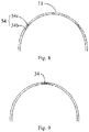
Fig. 8 is section view of an elastic headband of the head-mounted electronic device inFig. 7 . -
Fig. 9 is a section view of an elastic headband of a head-mounted electronic device provided in a fifth embodiment of the present disclosure. - In order to make the objectives, technical solutions and advantages of the present disclosure more definite and clear, the present disclosure is further illustrated in detail in combination with a plurality of embodiments and accompanying drawings. It should be understood that, the specific embodiments described herein are only used for explaining the present disclosure and not for limiting the present disclosure. In addition, the presentation doesn't represent actual scale relations among various elements, but is only intended for schematic illustration.
- In combination with
Fig. 1 to Fig. 3 , which are a schematic view, a block diagram and a partially exploded view of a head-mounted electronic device 5 provided in a first embodiment of the present disclosure, the head-mounted electronic device 5 is a head-mounted displayer in the embodiment, and includes a head-mountedheadphone 10, adisplay component 20, asensor component 31 and a control means 40. - The head-mounted
headphone 10 includes anelastic headband 11, twosound generators 12 and anaudio circuit 13. Theelastic headband 11 is U-shaped and configured to be deformed to provide a stress which presses the sound generator against ears of the user when the user wears theheadphone 10. Each of the twosound generators 12 includes amoving piece 14, a loudspeaker (not illustrated in the drawings), asounding surface 15 and anearmuff 16. Themoving piece 14 includes anannular wall 17 and an engaging portion 18 extending outwards from theannular wall 17. The loudspeaker is disposed in a space surrounded by theannular wall 17, and thesounding surface 15 is located at a side of the loudspeaker in which sound is emitted, that is the sound is emitted from thesounding surface 15. Theearmuff 16 is fixed to the soundingsurface 15. The engaging portion 18 is moveably connected to theelastic headband 11, so that thesound generator 12 may move with respect to theelastic headband 11, and thus it is convenient to adjust thesound generator 12 to positions suitable for different users to wear the head-mounted electronic device 5. - The
display component 20 includes a U-shapeddisplay member 21 configured for displaying an image to be viewed by the user, two connectingpieces 22 located at two opposite end parts of thedisplay member 21 and avideo circuit 23. Thevideo circuit 23 is accommodated in thedisplay member 21, an optical unit (not illustrated in the drawings) in cooperation with thevideo circuit 23 is accommodated in middle of thedisplay member 21, and thevideo circuit 23 has a micro display unit and a matched control circuit. An image displayed by the micro display unit is projected to user's eyes in an optical path defined by the optical unit, so that the user can view an enlarged virtual image. A working principle of thedisplay component 20 is familiar to those skilled in the related art, and thus will not be repeated in the present specification. The connectingpiece 22 has an annular shape, and theannular wall 17 of theheadphone 10 can just be partially accommodated in the connectingpiece 22, so that theannular wall 17 may rotate in the connectingpiece 22. - The
sensor component 31 is disposed to theheadphone 10 and configured for sensing a using state of the headphone. In the embodiment, thesensor component 31 includes a pressure sensor disposed to theheadphone 10. In the embodiment, the pressure sensor is disposed to the soundingsurface 15 of thesound generator 10, specifically an area of the soundingsurface 15 covered by theearmuff 16 or a part of theearmuff 16, so as to sense a pressure applied to theheadphone 10 when the user puts on theheadphone 10. A predetermined range of pressure, for example being larger than a certain pressure value, may be defined in advance. When the pressure value sensed by the pressure sensor is in the predetermined range, the headphone is judged to be in a wearing state, otherwise to be in a non-wearing state. Certainly, the pressure sensor is not limited to one as in the embodiment, and a plurality of pressure sensors may be provided, or each of the sound generators may be provided with the pressure sensor. In addition, the pressure sensor may also be disposed to a portion of theelastic headband 11 apt to contact the user's head, for example a middle portion of an inward surface of theelastic headband 11, which can also implement a same function. - The control means 40 is electrically connected to the
sensor component 31 and configured to control thedisplay component 20 to respond when thesensor component 31 senses that theheadphone 10 is switched between the wearing state and the non-wearing state. Certainly, the control means 40 may further control theheadphone 10 to respond. Specifically, the control means 40 is further electrically connected to theaudio circuit 13 and thevideo circuit 23, and is disposed in thedisplay component 20 or theheadphone 10, which may be determined according to an accommodating space defined by a specific structure. In the embodiment, when the pressure value sensed by the pressure sensor is larger than a pressure value A, i.e. in the above predetermined range, the headphone is in the wearing state; when the pressure value sensed by the pressure sensor is smaller than the pressure value A or a pressure value B (B is smaller than A), i.e. in a range corresponding to the non-wearing state, the headphone is in the non-wearing state. The control means 40 controls thedisplay component 10 in a video-play-paused state to play video, when the pressure value detected by the pressure sensor changing from the range corresponding to the non-wearing state into the predetermined range of the wearing state. Certainly, the control means 40 can further control theheadphone 10 to play the sound. - In the use process, after putting on the
headphone 10, the user can rotate thedisplay component 20 to a position where thedisplay component 20 has an included angle of substantial 90 degrees with theheadphone 10. At this moment, thedisplay component 20 is located in front close to the user's eyes, so that the user may view the images. After theheadphone 10 is put on, because of an elastic force of theelastic headband 11, the pressure value sensed by the pressure sensor is larger than a predetermined value, i.e. in the predetermined range, and thus theheadphone 10 is judged to be in the wearing state by the control means 40. In the process of using some functions of the head-mounted electronic device 5, for example playing the video, if the user has other matters to deal with and needs to take off the electronic device 5 and pause playing the video, the user may only need to take off the head-mounted electronic device 5. At this moment, as the pressure value sensed by the pressure sensor is almost zero, i.e. outside of the predetermined range, the control means 40 judges that the headphone is in the non-wearing state and controls thevideo circuit 23 and theaudio circuit 13 to stop working, thus pausing the play of video and audio. As the video play can be stopped without any other operations during the user taking off the head-mounted electronic device 5, it is very convenient for the user to use and the user experience is greatly improved. It should be pointed out that, pausing of the video play of thedisplay component 10 may indicate that the image is shown, but in a still state, or no image is shown, i.e. a blank screen, or the blank screen occurs automatically after the still image is shown for a period of time. All of the methods above can realize the purpose of pausing the video play. - Preferably, the headphone is judged to be in the wearing state when the pressure value sensed by the pressure sensor is in the predetermined range and the pressure value stays in the predetermined range over a first preset time, so that it is possible to identify that the headphone is in the wearing state more accurately.
- In other embodiments, the control means 40 may also control the
display component 20 to respond when thesensor component 31 senses that a relative position between theheadphone 10 and thedisplay component 20 is in a predetermined range, i.e., thedisplay component 20 in the video-play-paused state plays video when theheadphone 10 is switched from the non-wearing state to the wearing state. Preferably, for thedisplay component 20 in the video-play-paused state, when theheadphone 10 is switched from the non-wearing state to the wearing state and the wearing state lasts over a second preset time, the control means 40 controls thedisplay component 20 to play video and/or theheadphone 10 to output audio. Such design reserves a certain adjustment time for the user before playing video and/or audio, after the user puts on the head-mounted electronic device 5, which is beneficial for the user to view the video in a better state. Certainly, the function described in this paragraph and the preceding functions can be superposed in one same head-mounted electronic device 5. - In combination with
Fig. 4 and Fig. 5 , which are a schematic view and a partial section view of a head-mounted electronic device 6 provided in a second embodiment of the present disclosure, the second embodiment mainly differs from the first embodiment in asensor component 32. Thesensor component 32 includes afirst metal piece 32a and asecond metal piece 32b, and at least a part of theearmuff 10 is located between thefirst metal piece 32a and thesecond metal piece 32b. In the embodiment, thefirst metal piece 32a may be attached to an outside coating of theearmuff 10, for example an inner side of leather, and thesecond metal piece 32b may be attached to the sounding surface. In this case, a part of filler (for example foam materials) of theearmuff 10 is erected between thefirst metal piece 32a and thesecond metal piece 32b, and hence thesensor component 32 is configured as a capacitor. When the user puts on theheadphone 10, a distance between thefirst metal piece 32a and thesecond metal piece 32b changes, so a capacitance of thesensor component 32 changes. Accordingly, a change state of the capacitance reflects that whether the user wears theheadphone 10 or not. Other working principles are similar to those of the first embodiment, and will not be repeated herein. - In combination with
Fig. 6 , which is a schematic view and a partial section view of a head-mounted electronic device 7 provided in a third embodiment of the present disclosure, the third embodiment mainly differs from the first embodiment in asensor component 33. Thesensor component 33 includes a capacitive touch screen disposed to theearmuff 16. For example, the capacitive touch screen is disposed to an outer surface of theearmuff 16 directly facing the user, i.e., the capacitive touch screen contacts the skin of the user directly for sensing. Or, the capacitive touch screen is disposed to an inner side of the outside coating of theearmuff 16, i.e., the capacitive touch screen contacts the skin of the user indirectly for sensing. It may be understood that a position of the capacitive touch screen is not limited, as long as the capacitive touch screen may sense the contact with the user. Certainly, the capacitive touch screen may also be disposed to the soundingsurface 15. In the third embodiment, it is possible to know whether the headphone is in the wearing state by using the capacitive touch screen to sense its contact with the skin of the user. In the present disclosure, the sensed contact with the skin of the user includes the above direct contact and the above indirect contact. Other principles are similar to those of the first embodiment, and will not be repeated herein. - In combination with
Fig. 7 andFig. 8 , which are a schematic view of a head-mounted electronic device provided in a fourth embodiment of the present disclosure and a section view of an elastic headband of the head-mounted electronic device, the fourth embodiment mainly differs from the first embodiment in asensor component 34. Thesensor component 34 is an angle sensor disposed to theelastic headband 11, and includes a fixedportion 34a fixed to the elastic headband and two movable portions 34b located at two sides of the fixedportion 34a. The movable portion 34b keeps abutting against theelastic headband 11. Accordingly, when the elastic headband is deformed at a position of the angle sensor, the angle sensor may sense such deformation. In the embodiment, two angle sensors are respectively provided at two sides of the middle of theelastic headband 11 where the deformation extent is relatively large, so as to sense the angel change accurately. It should be understood that, the number and the positions of the angle sensors are not limited to the above manner. For example, one angel sensor may be provided at the middle of theelastic headband 11. As illustrated inFig. 9 , in the fifth embodiment, the angle sensor senses whether theelastic headband 11 is expanded when the user puts on the headphone by sensing the deformation of theelastic headband 11, so as to determine whether the headphone is in the wearing state. The other working principles are similar to those of the first embodiment, and will not be repeated herein. - Certainly, in the various embodiments described above, specific solutions in different embodiments can be used in combination with one another. For example, the pressure sensor is used in conjunction with the touch screen, thus achieving a more accurate judgment. In addition, it should be noted that, the above head-mounted electronic device is not limited to playing the video, but may also be another head-mounted electronic device, such as a head-mounted game device, a head-mounted navigation device and the like. All of the head-mounted electronic devices having content of the present disclosure can realize the above convenient function of automatic control.
- The above descriptions are only preferable embodiments of the present disclosure and are not intended to limit the present disclosure. Any modifications, equal alternatives, and improvements made within the spirit and principle of the present disclosure should be included in the protection scope of the present disclosure.
Claims (13)
- A head-mounted electronic device, comprising:a U-shaped head-mounted headphone;a U-shaped display component rotatably connected to the headphone;a sensor component disposed to the headphone and configured to sense a wearing state of the headphone; anda control means electrically connected to the sensor component and configured to control the display component and/or the headphone to make a correlative response when the sensor component senses that the headphone is switched between the wearing state and a non-wearing state.
- The head-mounted electronic device according to claim 1, wherein the sensor component comprises at least one pressure sensor, and the headphone is judged to be in the wearing state when a pressure value sensed by the pressure sensor is in a predetermined range.
- The head-mounted electronic device according to claim 2, wherein the headphone is judged to be in the wearing state when the pressure value sensed by the pressure sensor is in the predetermined range and stays in the predetermined range over a first preset time.
- The head-mounted electronic device according to claim 2, wherein the headphone comprises a U-shaped elastic headband and two sound generators connected to the elastic headband, and the pressure sensor is disposed to the sound generator.
- The head-mounted electronic device according to claim 4, wherein each of the two sound generators comprises a sounding surface and an earmuff, sound is emitted from the sounding surface, and the earmuff is disposed to the sounding surface,
the earmuff is configured to be pressed in the wearing state,
the sensor component is disposed to the sounding surface or the earmuff. - The head-mounted electronic device according to claim 1, wherein the headphone comprises two sound generators, each of the two sound generators has an earmuff, and the earmuff is configured to be pressed in the wearing state,
the sensor component comprises a first metal piece and a second metal piece, and at least a part of the earmuff is located between the first metal piece and the second metal piece,
the headphone is judged to be in the wearing state when the sensor component senses that a capacitance value between the first metal piece and the second metal piece is in a predetermined range. - The head-mounted electronic device according to claim 1, wherein the headphone comprises two sound generators, each of the two sound generators comprises a sounding surface and an earmuff, sound is emitted from the sounding surface, and the earmuff is disposed to the sounding surface,
the sensor component comprises at least one capacitive touch screen disposed to the sounding surface or the earmuff, and
the headphone is judged to be in the wearing state when the capacitive touch screen senses a skin touch. - The head-mounted electronic device according to claim 1, wherein the sensor component comprises at least one angle sensor disposed to the elastic headband, and the headphone is judged to be in the wearing state when an angle value sensed by the angle sensor is in a predetermined range.
- The head-mounted electronic device according to claim 8, wherein the sensor component comprises one angle sensor disposed at a middle portion of the elastic headband and configured to sense a deformation degree of the elastic headband.
- The head-mounted electronic device according to claim 8, wherein the sensor component comprises two angle sensors respectively disposed at two sides of a middle portion of the elastic headband and configured to sense a deformation degree of the elastic headband.
- The head-mounted electronic device according to any one of claims 1 to 10, wherein the response made by the display component comprises that the display component in a video-play state pauses the video play when the headphone is switched from the wearing state to the non-wearing state.
- The head-mounted electronic device according to any one of claims 1 to 10, wherein the response made by the display component comprises that the display component in a video-play-paused state plays video when the headphone is switched from the non-wearing state to the wearing state.
- The head-mounted electronic device according to claim 12, wherein when the headphone is switched from the non-wearing state to the wearing state and the wearing state lasts over a second preset time, the display component plays video.
Applications Claiming Priority (1)
| Application Number | Priority Date | Filing Date | Title |
|---|---|---|---|
| PCT/CN2015/075918 WO2016155019A1 (en) | 2015-04-03 | 2015-04-03 | Head-mounted electronic device |
Publications (3)
| Publication Number | Publication Date |
|---|---|
| EP3280153A1 true EP3280153A1 (en) | 2018-02-07 |
| EP3280153A4 EP3280153A4 (en) | 2018-12-05 |
| EP3280153B1 EP3280153B1 (en) | 2020-03-11 |
Family
ID=57003912
Family Applications (1)
| Application Number | Title | Priority Date | Filing Date |
|---|---|---|---|
| EP15886989.1A Active EP3280153B1 (en) | 2015-04-03 | 2015-04-03 | Head-mounted electronic device |
Country Status (6)
| Country | Link |
|---|---|
| US (1) | US20180039086A1 (en) |
| EP (1) | EP3280153B1 (en) |
| JP (1) | JP2018512816A (en) |
| KR (1) | KR20170131460A (en) |
| CN (1) | CN106256135A (en) |
| WO (1) | WO2016155019A1 (en) |
Cited By (1)
| Publication number | Priority date | Publication date | Assignee | Title |
|---|---|---|---|---|
| EP3351995A4 (en) * | 2015-09-14 | 2019-05-22 | Shenzhen Royole Technologies Co., Ltd | VISIOCASQUE APPARATUS |
Families Citing this family (25)
| Publication number | Priority date | Publication date | Assignee | Title |
|---|---|---|---|---|
| CN106291121B (en) * | 2016-07-29 | 2023-10-13 | 歌尔股份有限公司 | Wearing state detection method of wearable device and wearable device |
| KR20180054228A (en) * | 2016-11-15 | 2018-05-24 | 삼성전자주식회사 | Method for providing content and electronic device thereof |
| US10200774B1 (en) * | 2016-11-30 | 2019-02-05 | Google Llc | Sensor cord construction to prevent capacitance variation |
| US10291976B2 (en) * | 2017-03-31 | 2019-05-14 | Apple Inc. | Electronic devices with configurable capacitive proximity sensors |
| CN108174319A (en) * | 2018-01-11 | 2018-06-15 | 中国地质大学(武汉) | An earphone intelligent control device based on MEMS pressure sensor |
| US10856064B2 (en) * | 2018-04-27 | 2020-12-01 | Avnera Corporation | Operation of a personal audio device during insertion detection |
| CN109361981B (en) * | 2018-11-05 | 2020-07-28 | 全芯科微电子科技(深圳)有限公司 | Bluetooth headset and connection state control method thereof |
| US11265640B2 (en) * | 2019-04-04 | 2022-03-01 | Tymphany Acoustic Technology (Huizhou) Co., Ltd. | Headphone assembly and headphone controlling method |
| US11172282B2 (en) * | 2019-08-08 | 2021-11-09 | Ite Tech. Inc. | Earphone and earphone wearing detection method |
| KR102822425B1 (en) * | 2019-08-30 | 2025-06-18 | 엘지전자 주식회사 | Electronic device |
| JP2021145276A (en) * | 2020-03-13 | 2021-09-24 | 株式会社オーディオテクニカ | Headphone device |
| CN111538156B (en) * | 2020-04-24 | 2022-07-19 | 北京易智时代数字科技有限公司 | Head posture tracking method of head-mounted VR equipment |
| CN111538155B (en) * | 2020-04-24 | 2022-07-19 | 北京易智时代数字科技有限公司 | Wear-type VR equipment |
| CN111654777B (en) | 2020-06-29 | 2025-08-19 | 歌尔科技有限公司 | Head-mounted display device and head-mounted display assembly |
| US11272279B1 (en) | 2020-09-16 | 2022-03-08 | Apple Inc. | Headphones with off-center pivoting earpiece |
| US11184696B1 (en) | 2020-09-16 | 2021-11-23 | Apple Inc. | Wireless headphones with slot antenna |
| US11272280B1 (en) | 2020-09-16 | 2022-03-08 | Apple Inc. | Earpiece with cushion retention |
| US11457300B2 (en) | 2020-09-16 | 2022-09-27 | Apple Inc. | Support structure for earpiece cushion |
| US11190878B1 (en) * | 2020-09-16 | 2021-11-30 | Apple Inc. | Headphones with on-head detection |
| CN112261536B (en) * | 2020-10-20 | 2023-08-04 | 深圳市凯狮博电子有限公司 | Earphone control method, earphone control device, terminal equipment and storage medium |
| CN112543394B (en) * | 2020-11-09 | 2023-01-17 | 苏州创捷传媒展览股份有限公司 | Earphone play control system based on conduction formula pressure structure |
| CN114979871B (en) * | 2021-02-24 | 2023-12-08 | 华为技术有限公司 | Earphone |
| CN113709622B (en) * | 2021-09-23 | 2022-11-01 | 歌尔科技有限公司 | Method and device for detecting state of head-mounted electronic equipment, head-mounted electronic equipment and medium |
| KR102423905B1 (en) * | 2021-12-15 | 2022-07-21 | 박준 | Auditory transmission method using bone conduction in HMD environment |
| WO2026014680A1 (en) * | 2024-07-12 | 2026-01-15 | 주식회사 긱스로프트 | Wearable device comprising at least one camera and operation method thereof |
Family Cites Families (31)
| Publication number | Priority date | Publication date | Assignee | Title |
|---|---|---|---|---|
| DE4034096A1 (en) * | 1990-06-27 | 1992-01-09 | Vielberth Inst Entw & Forsch | Automatic on=off switching circuitry for mobile appts. - has sensor(s) responsive to movement or change and charge and discharge capacitors responsive to sensor signals |
| US5144678A (en) * | 1991-02-04 | 1992-09-01 | Golden West Communications Inc. | Automatically switched headset |
| JP2004085476A (en) * | 2002-08-28 | 2004-03-18 | Sony Corp | Head tracking method and apparatus |
| WO2004061519A1 (en) * | 2002-12-24 | 2004-07-22 | Nikon Corporation | Head mount display |
| JP2004236242A (en) * | 2003-01-31 | 2004-08-19 | Nikon Corp | Head mounted display |
| JP4299170B2 (en) * | 2004-03-23 | 2009-07-22 | クラリオン株式会社 | Multimedia playback device, multimedia playback system, headphone and chair |
| JP2006041843A (en) * | 2004-07-26 | 2006-02-09 | Toshiba Corp | Bone conduction speaker device |
| KR20070070815A (en) * | 2005-12-29 | 2007-07-04 | 주식회사 레인콤 | Portable multimedia device with power control and power control method |
| KR100783099B1 (en) * | 2006-05-16 | 2007-12-07 | 크레신 주식회사 | Hermetic headphones with a microphone and how to use them |
| US8134593B2 (en) * | 2006-11-22 | 2012-03-13 | Nikon Corporation | Output device |
| JP5299866B2 (en) * | 2009-05-19 | 2013-09-25 | 日立コンシューマエレクトロニクス株式会社 | Video display device |
| US20110007908A1 (en) * | 2009-07-13 | 2011-01-13 | Plantronics, Inc. | Speaker Capacitive Sensor |
| US8665177B2 (en) * | 2010-02-05 | 2014-03-04 | Kopin Corporation | Touch sensor for controlling eyewear |
| TW201131145A (en) * | 2010-03-01 | 2011-09-16 | Compal Electronics Inc | Capacitace detecting module and electronic apparatus |
| KR200461682Y1 (en) * | 2010-03-03 | 2012-07-30 | 주식회사 이노디자인 | Headset with a device reading 3 Dimension visual images |
| JP2012034263A (en) * | 2010-08-02 | 2012-02-16 | Panasonic Corp | Portable terminal device |
| CN102447991A (en) * | 2010-10-14 | 2012-05-09 | 钰宝科技股份有限公司 | Headset with automatic power saving function |
| JP5829439B2 (en) * | 2011-06-20 | 2015-12-09 | 千曲技研株式会社 | Waste paper storage unit |
| JP5923926B2 (en) * | 2011-10-24 | 2016-05-25 | ソニー株式会社 | Head mounted display and method for controlling head mounted display |
| KR20140105479A (en) * | 2011-12-23 | 2014-09-01 | 톰슨 라이센싱 | Computer device with power-consumption management and method for managing power-consumption of computer device |
| US20140064500A1 (en) * | 2012-08-30 | 2014-03-06 | Monster | Automatic Power Adjusting Headphones |
| CN203057476U (en) * | 2013-01-11 | 2013-07-10 | 易力声科技(深圳)有限公司 | Tension force detection-based intelligent switching control headphone |
| CN104113794A (en) * | 2013-04-22 | 2014-10-22 | 联想(北京)有限公司 | Information processing method, information processing system and headset |
| KR101509169B1 (en) * | 2013-05-07 | 2015-04-07 | 배영식 | Head mounted display |
| KR102191867B1 (en) * | 2013-07-10 | 2020-12-16 | 엘지전자 주식회사 | Apparatus and Method for Head Mounted Display Device with multiple user interface formats |
| CN203313378U (en) * | 2013-07-12 | 2013-11-27 | 黄通兵 | Loudspeaker connecting device convenient to store and novel glasses-type facility |
| JP2015037246A (en) * | 2013-08-13 | 2015-02-23 | ソニー株式会社 | Headphone type acoustic device and control method therefor |
| KR102112546B1 (en) * | 2013-10-01 | 2020-05-19 | 삼성전자 주식회사 | Apparatus and method for adjusting the air pressure inside of an ear |
| CN103686515A (en) * | 2013-12-06 | 2014-03-26 | 青岛歌尔声学科技有限公司 | Earphone system and control method with automatic sensing detection and control functions |
| CN106465458B (en) * | 2014-05-23 | 2019-12-13 | 三星电子株式会社 | Method and apparatus for providing notifications |
| CN204229050U (en) * | 2014-12-03 | 2015-03-25 | 成都贝思达光电科技有限公司 | A kind of portable turning video eyeglasses |
-
2015
- 2015-04-03 EP EP15886989.1A patent/EP3280153B1/en active Active
- 2015-04-03 CN CN201580001426.1A patent/CN106256135A/en active Pending
- 2015-04-03 KR KR1020177027187A patent/KR20170131460A/en not_active Ceased
- 2015-04-03 JP JP2017552076A patent/JP2018512816A/en active Pending
- 2015-04-03 WO PCT/CN2015/075918 patent/WO2016155019A1/en not_active Ceased
- 2015-04-03 US US15/553,432 patent/US20180039086A1/en not_active Abandoned
Cited By (1)
| Publication number | Priority date | Publication date | Assignee | Title |
|---|---|---|---|---|
| EP3351995A4 (en) * | 2015-09-14 | 2019-05-22 | Shenzhen Royole Technologies Co., Ltd | VISIOCASQUE APPARATUS |
Also Published As
| Publication number | Publication date |
|---|---|
| KR20170131460A (en) | 2017-11-29 |
| WO2016155019A1 (en) | 2016-10-06 |
| JP2018512816A (en) | 2018-05-17 |
| EP3280153A4 (en) | 2018-12-05 |
| CN106256135A (en) | 2016-12-21 |
| EP3280153B1 (en) | 2020-03-11 |
| US20180039086A1 (en) | 2018-02-08 |
Similar Documents
| Publication | Publication Date | Title |
|---|---|---|
| US20180039086A1 (en) | Head-mounted electronic device | |
| CN208953789U (en) | Head mounted display worn by the user | |
| US10303244B2 (en) | Information processing apparatus, information processing method, and computer program | |
| CN106802482B (en) | Connector and Head Mounted Display | |
| KR102524641B1 (en) | Head mounted display device and method for controlling the same | |
| US20180329672A1 (en) | Volume adjustment on hinged multi-screen device | |
| JP7218376B2 (en) | Eye-tracking method and apparatus | |
| WO2017051595A1 (en) | Information processing device, information processing method and program | |
| US11334157B1 (en) | Wearable device and user input system with active sensing for computing devices and artificial reality environments | |
| WO2016013272A1 (en) | Information processing device, information processing method and image display system | |
| KR20200112837A (en) | Information processing device, information processing method and program | |
| KR20200046301A (en) | A smart user equipment connected to a head mounted display and control method therefor | |
| CN105260016B (en) | An information processing method and electronic device | |
| WO2018019256A1 (en) | Virtual reality system, and method and device for adjusting visual angle thereof | |
| US20190394555A1 (en) | Headphones | |
| CN107003519A (en) | Brightness adjusting method and head-wearing display device for head-wearing display device | |
| US20200273434A1 (en) | Image display system, storage medium having stored therein image display program, image display method, and display device | |
| JP6964142B2 (en) | Information processing equipment, information processing methods, and programs | |
| CN109688325B (en) | An image display method and terminal device | |
| US20120058825A1 (en) | Game apparatus, game control method, and information recording medium | |
| KR20190131737A (en) | Wearable electronic device that provides guide information based on contact state with respect to exteranl object and operating mehtod of the same | |
| US20240256031A1 (en) | Systems and methods for gaze-assisted gesture control | |
| CN111158492B (en) | Video editing method and head mounted device | |
| KR20170089228A (en) | Method for controlling a virtual reality head mounted display using smart phone | |
| KR102606116B1 (en) | Head mounted display and, the controlling method thereof |
Legal Events
| Date | Code | Title | Description |
|---|---|---|---|
| STAA | Information on the status of an ep patent application or granted ep patent |
Free format text: STATUS: THE INTERNATIONAL PUBLICATION HAS BEEN MADE |
|
| PUAI | Public reference made under article 153(3) epc to a published international application that has entered the european phase |
Free format text: ORIGINAL CODE: 0009012 |
|
| STAA | Information on the status of an ep patent application or granted ep patent |
Free format text: STATUS: REQUEST FOR EXAMINATION WAS MADE |
|
| 17P | Request for examination filed |
Effective date: 20170803 |
|
| AK | Designated contracting states |
Kind code of ref document: A1 Designated state(s): AL AT BE BG CH CY CZ DE DK EE ES FI FR GB GR HR HU IE IS IT LI LT LU LV MC MK MT NL NO PL PT RO RS SE SI SK SM TR |
|
| AX | Request for extension of the european patent |
Extension state: BA ME |
|
| DAV | Request for validation of the european patent (deleted) | ||
| DAX | Request for extension of the european patent (deleted) | ||
| A4 | Supplementary search report drawn up and despatched |
Effective date: 20181031 |
|
| RIC1 | Information provided on ipc code assigned before grant |
Ipc: G03B 29/00 20060101ALI20181025BHEP Ipc: H04R 5/033 20060101ALN20181025BHEP Ipc: H04R 1/10 20060101AFI20181025BHEP |
|
| GRAP | Despatch of communication of intention to grant a patent |
Free format text: ORIGINAL CODE: EPIDOSNIGR1 |
|
| STAA | Information on the status of an ep patent application or granted ep patent |
Free format text: STATUS: GRANT OF PATENT IS INTENDED |
|
| RIC1 | Information provided on ipc code assigned before grant |
Ipc: H04R 5/033 20060101ALN20191009BHEP Ipc: G03B 29/00 20060101ALI20191009BHEP Ipc: H04R 1/10 20060101AFI20191009BHEP |
|
| INTG | Intention to grant announced |
Effective date: 20191029 |
|
| GRAS | Grant fee paid |
Free format text: ORIGINAL CODE: EPIDOSNIGR3 |
|
| GRAA | (expected) grant |
Free format text: ORIGINAL CODE: 0009210 |
|
| STAA | Information on the status of an ep patent application or granted ep patent |
Free format text: STATUS: THE PATENT HAS BEEN GRANTED |
|
| AK | Designated contracting states |
Kind code of ref document: B1 Designated state(s): AL AT BE BG CH CY CZ DE DK EE ES FI FR GB GR HR HU IE IS IT LI LT LU LV MC MK MT NL NO PL PT RO RS SE SI SK SM TR |
|
| REG | Reference to a national code |
Ref country code: GB Ref legal event code: FG4D |
|
| REG | Reference to a national code |
Ref country code: CH Ref legal event code: EP |
|
| REG | Reference to a national code |
Ref country code: AT Ref legal event code: REF Ref document number: 1244657 Country of ref document: AT Kind code of ref document: T Effective date: 20200315 |
|
| REG | Reference to a national code |
Ref country code: IE Ref legal event code: FG4D |
|
| REG | Reference to a national code |
Ref country code: DE Ref legal event code: R096 Ref document number: 602015048822 Country of ref document: DE |
|
| PGFP | Annual fee paid to national office [announced via postgrant information from national office to epo] |
Ref country code: GB Payment date: 20200326 Year of fee payment: 6 |
|
| PG25 | Lapsed in a contracting state [announced via postgrant information from national office to epo] |
Ref country code: RS Free format text: LAPSE BECAUSE OF FAILURE TO SUBMIT A TRANSLATION OF THE DESCRIPTION OR TO PAY THE FEE WITHIN THE PRESCRIBED TIME-LIMIT Effective date: 20200311 Ref country code: FI Free format text: LAPSE BECAUSE OF FAILURE TO SUBMIT A TRANSLATION OF THE DESCRIPTION OR TO PAY THE FEE WITHIN THE PRESCRIBED TIME-LIMIT Effective date: 20200311 Ref country code: NO Free format text: LAPSE BECAUSE OF FAILURE TO SUBMIT A TRANSLATION OF THE DESCRIPTION OR TO PAY THE FEE WITHIN THE PRESCRIBED TIME-LIMIT Effective date: 20200611 |
|
| REG | Reference to a national code |
Ref country code: NL Ref legal event code: MP Effective date: 20200311 |
|
| PG25 | Lapsed in a contracting state [announced via postgrant information from national office to epo] |
Ref country code: BG Free format text: LAPSE BECAUSE OF FAILURE TO SUBMIT A TRANSLATION OF THE DESCRIPTION OR TO PAY THE FEE WITHIN THE PRESCRIBED TIME-LIMIT Effective date: 20200611 Ref country code: LV Free format text: LAPSE BECAUSE OF FAILURE TO SUBMIT A TRANSLATION OF THE DESCRIPTION OR TO PAY THE FEE WITHIN THE PRESCRIBED TIME-LIMIT Effective date: 20200311 Ref country code: SE Free format text: LAPSE BECAUSE OF FAILURE TO SUBMIT A TRANSLATION OF THE DESCRIPTION OR TO PAY THE FEE WITHIN THE PRESCRIBED TIME-LIMIT Effective date: 20200311 Ref country code: HR Free format text: LAPSE BECAUSE OF FAILURE TO SUBMIT A TRANSLATION OF THE DESCRIPTION OR TO PAY THE FEE WITHIN THE PRESCRIBED TIME-LIMIT Effective date: 20200311 Ref country code: GR Free format text: LAPSE BECAUSE OF FAILURE TO SUBMIT A TRANSLATION OF THE DESCRIPTION OR TO PAY THE FEE WITHIN THE PRESCRIBED TIME-LIMIT Effective date: 20200612 |
|
| REG | Reference to a national code |
Ref country code: LT Ref legal event code: MG4D |
|
| PG25 | Lapsed in a contracting state [announced via postgrant information from national office to epo] |
Ref country code: NL Free format text: LAPSE BECAUSE OF FAILURE TO SUBMIT A TRANSLATION OF THE DESCRIPTION OR TO PAY THE FEE WITHIN THE PRESCRIBED TIME-LIMIT Effective date: 20200311 |
|
| PG25 | Lapsed in a contracting state [announced via postgrant information from national office to epo] |
Ref country code: SM Free format text: LAPSE BECAUSE OF FAILURE TO SUBMIT A TRANSLATION OF THE DESCRIPTION OR TO PAY THE FEE WITHIN THE PRESCRIBED TIME-LIMIT Effective date: 20200311 Ref country code: EE Free format text: LAPSE BECAUSE OF FAILURE TO SUBMIT A TRANSLATION OF THE DESCRIPTION OR TO PAY THE FEE WITHIN THE PRESCRIBED TIME-LIMIT Effective date: 20200311 Ref country code: IS Free format text: LAPSE BECAUSE OF FAILURE TO SUBMIT A TRANSLATION OF THE DESCRIPTION OR TO PAY THE FEE WITHIN THE PRESCRIBED TIME-LIMIT Effective date: 20200711 Ref country code: CZ Free format text: LAPSE BECAUSE OF FAILURE TO SUBMIT A TRANSLATION OF THE DESCRIPTION OR TO PAY THE FEE WITHIN THE PRESCRIBED TIME-LIMIT Effective date: 20200311 Ref country code: RO Free format text: LAPSE BECAUSE OF FAILURE TO SUBMIT A TRANSLATION OF THE DESCRIPTION OR TO PAY THE FEE WITHIN THE PRESCRIBED TIME-LIMIT Effective date: 20200311 Ref country code: SK Free format text: LAPSE BECAUSE OF FAILURE TO SUBMIT A TRANSLATION OF THE DESCRIPTION OR TO PAY THE FEE WITHIN THE PRESCRIBED TIME-LIMIT Effective date: 20200311 Ref country code: PT Free format text: LAPSE BECAUSE OF FAILURE TO SUBMIT A TRANSLATION OF THE DESCRIPTION OR TO PAY THE FEE WITHIN THE PRESCRIBED TIME-LIMIT Effective date: 20200805 Ref country code: LT Free format text: LAPSE BECAUSE OF FAILURE TO SUBMIT A TRANSLATION OF THE DESCRIPTION OR TO PAY THE FEE WITHIN THE PRESCRIBED TIME-LIMIT Effective date: 20200311 |
|
| REG | Reference to a national code |
Ref country code: DE Ref legal event code: R119 Ref document number: 602015048822 Country of ref document: DE |
|
| REG | Reference to a national code |
Ref country code: AT Ref legal event code: MK05 Ref document number: 1244657 Country of ref document: AT Kind code of ref document: T Effective date: 20200311 |
|
| REG | Reference to a national code |
Ref country code: CH Ref legal event code: PL |
|
| PG25 | Lapsed in a contracting state [announced via postgrant information from national office to epo] |
Ref country code: MC Free format text: LAPSE BECAUSE OF FAILURE TO SUBMIT A TRANSLATION OF THE DESCRIPTION OR TO PAY THE FEE WITHIN THE PRESCRIBED TIME-LIMIT Effective date: 20200311 |
|
| PLBE | No opposition filed within time limit |
Free format text: ORIGINAL CODE: 0009261 |
|
| STAA | Information on the status of an ep patent application or granted ep patent |
Free format text: STATUS: NO OPPOSITION FILED WITHIN TIME LIMIT |
|
| PG25 | Lapsed in a contracting state [announced via postgrant information from national office to epo] |
Ref country code: IT Free format text: LAPSE BECAUSE OF FAILURE TO SUBMIT A TRANSLATION OF THE DESCRIPTION OR TO PAY THE FEE WITHIN THE PRESCRIBED TIME-LIMIT Effective date: 20200311 Ref country code: LU Free format text: LAPSE BECAUSE OF NON-PAYMENT OF DUE FEES Effective date: 20200403 Ref country code: DE Free format text: LAPSE BECAUSE OF NON-PAYMENT OF DUE FEES Effective date: 20201103 Ref country code: LI Free format text: LAPSE BECAUSE OF NON-PAYMENT OF DUE FEES Effective date: 20200430 Ref country code: CH Free format text: LAPSE BECAUSE OF NON-PAYMENT OF DUE FEES Effective date: 20200430 Ref country code: DK Free format text: LAPSE BECAUSE OF FAILURE TO SUBMIT A TRANSLATION OF THE DESCRIPTION OR TO PAY THE FEE WITHIN THE PRESCRIBED TIME-LIMIT Effective date: 20200311 Ref country code: AT Free format text: LAPSE BECAUSE OF FAILURE TO SUBMIT A TRANSLATION OF THE DESCRIPTION OR TO PAY THE FEE WITHIN THE PRESCRIBED TIME-LIMIT Effective date: 20200311 Ref country code: ES Free format text: LAPSE BECAUSE OF FAILURE TO SUBMIT A TRANSLATION OF THE DESCRIPTION OR TO PAY THE FEE WITHIN THE PRESCRIBED TIME-LIMIT Effective date: 20200311 |
|
| REG | Reference to a national code |
Ref country code: BE Ref legal event code: MM Effective date: 20200430 |
|
| 26N | No opposition filed |
Effective date: 20201214 |
|
| PG25 | Lapsed in a contracting state [announced via postgrant information from national office to epo] |
Ref country code: BE Free format text: LAPSE BECAUSE OF NON-PAYMENT OF DUE FEES Effective date: 20200430 Ref country code: PL Free format text: LAPSE BECAUSE OF FAILURE TO SUBMIT A TRANSLATION OF THE DESCRIPTION OR TO PAY THE FEE WITHIN THE PRESCRIBED TIME-LIMIT Effective date: 20200311 Ref country code: SI Free format text: LAPSE BECAUSE OF FAILURE TO SUBMIT A TRANSLATION OF THE DESCRIPTION OR TO PAY THE FEE WITHIN THE PRESCRIBED TIME-LIMIT Effective date: 20200311 |
|
| PG25 | Lapsed in a contracting state [announced via postgrant information from national office to epo] |
Ref country code: IE Free format text: LAPSE BECAUSE OF NON-PAYMENT OF DUE FEES Effective date: 20200403 Ref country code: FR Free format text: LAPSE BECAUSE OF NON-PAYMENT OF DUE FEES Effective date: 20200511 |
|
| GBPC | Gb: european patent ceased through non-payment of renewal fee |
Effective date: 20210403 |
|
| PG25 | Lapsed in a contracting state [announced via postgrant information from national office to epo] |
Ref country code: GB Free format text: LAPSE BECAUSE OF NON-PAYMENT OF DUE FEES Effective date: 20210403 |
|
| PG25 | Lapsed in a contracting state [announced via postgrant information from national office to epo] |
Ref country code: TR Free format text: LAPSE BECAUSE OF FAILURE TO SUBMIT A TRANSLATION OF THE DESCRIPTION OR TO PAY THE FEE WITHIN THE PRESCRIBED TIME-LIMIT Effective date: 20200311 Ref country code: MT Free format text: LAPSE BECAUSE OF FAILURE TO SUBMIT A TRANSLATION OF THE DESCRIPTION OR TO PAY THE FEE WITHIN THE PRESCRIBED TIME-LIMIT Effective date: 20200311 Ref country code: CY Free format text: LAPSE BECAUSE OF FAILURE TO SUBMIT A TRANSLATION OF THE DESCRIPTION OR TO PAY THE FEE WITHIN THE PRESCRIBED TIME-LIMIT Effective date: 20200311 |
|
| PG25 | Lapsed in a contracting state [announced via postgrant information from national office to epo] |
Ref country code: MK Free format text: LAPSE BECAUSE OF FAILURE TO SUBMIT A TRANSLATION OF THE DESCRIPTION OR TO PAY THE FEE WITHIN THE PRESCRIBED TIME-LIMIT Effective date: 20200311 Ref country code: AL Free format text: LAPSE BECAUSE OF FAILURE TO SUBMIT A TRANSLATION OF THE DESCRIPTION OR TO PAY THE FEE WITHIN THE PRESCRIBED TIME-LIMIT Effective date: 20200311 |