EP3279979A1 - Lithium complex oxide for lithium secondary battery positive active material and a method of preparing the same - Google Patents
Lithium complex oxide for lithium secondary battery positive active material and a method of preparing the same Download PDFInfo
- Publication number
- EP3279979A1 EP3279979A1 EP17160908.4A EP17160908A EP3279979A1 EP 3279979 A1 EP3279979 A1 EP 3279979A1 EP 17160908 A EP17160908 A EP 17160908A EP 3279979 A1 EP3279979 A1 EP 3279979A1
- Authority
- EP
- European Patent Office
- Prior art keywords
- secondary particle
- positive active
- active material
- lithium
- comparison
- Prior art date
- Legal status (The legal status is an assumption and is not a legal conclusion. Google has not performed a legal analysis and makes no representation as to the accuracy of the status listed.)
- Granted
Links
Images


Classifications
-
- H—ELECTRICITY
- H01—ELECTRIC ELEMENTS
- H01M—PROCESSES OR MEANS, e.g. BATTERIES, FOR THE DIRECT CONVERSION OF CHEMICAL ENERGY INTO ELECTRICAL ENERGY
- H01M4/00—Electrodes
- H01M4/02—Electrodes composed of, or comprising, active material
- H01M4/36—Selection of substances as active materials, active masses, active liquids
- H01M4/48—Selection of substances as active materials, active masses, active liquids of inorganic oxides or hydroxides
- H01M4/485—Selection of substances as active materials, active masses, active liquids of inorganic oxides or hydroxides of mixed oxides or hydroxides for inserting or intercalating light metals, e.g. LiTi2O4 or LiTi2OxFy
-
- H—ELECTRICITY
- H01—ELECTRIC ELEMENTS
- H01M—PROCESSES OR MEANS, e.g. BATTERIES, FOR THE DIRECT CONVERSION OF CHEMICAL ENERGY INTO ELECTRICAL ENERGY
- H01M4/00—Electrodes
- H01M4/02—Electrodes composed of, or comprising, active material
- H01M4/36—Selection of substances as active materials, active masses, active liquids
- H01M4/58—Selection of substances as active materials, active masses, active liquids of inorganic compounds other than oxides or hydroxides, e.g. sulfides, selenides, tellurides, halogenides or LiCoFy; of polyanionic structures, e.g. phosphates, silicates or borates
- H01M4/581—Chalcogenides or intercalation compounds thereof
-
- C—CHEMISTRY; METALLURGY
- C01—INORGANIC CHEMISTRY
- C01G—COMPOUNDS CONTAINING METALS NOT COVERED BY SUBCLASSES C01D OR C01F
- C01G53/00—Compounds of nickel
- C01G53/40—Nickelates
- C01G53/42—Nickelates containing alkali metals, e.g. LiNiO2
-
- H—ELECTRICITY
- H01—ELECTRIC ELEMENTS
- H01M—PROCESSES OR MEANS, e.g. BATTERIES, FOR THE DIRECT CONVERSION OF CHEMICAL ENERGY INTO ELECTRICAL ENERGY
- H01M10/00—Secondary cells; Manufacture thereof
- H01M10/05—Accumulators with non-aqueous electrolyte
- H01M10/052—Li-accumulators
-
- H—ELECTRICITY
- H01—ELECTRIC ELEMENTS
- H01M—PROCESSES OR MEANS, e.g. BATTERIES, FOR THE DIRECT CONVERSION OF CHEMICAL ENERGY INTO ELECTRICAL ENERGY
- H01M10/00—Secondary cells; Manufacture thereof
- H01M10/05—Accumulators with non-aqueous electrolyte
- H01M10/052—Li-accumulators
- H01M10/0525—Rocking-chair batteries, i.e. batteries with lithium insertion or intercalation in both electrodes; Lithium-ion batteries
-
- H—ELECTRICITY
- H01—ELECTRIC ELEMENTS
- H01M—PROCESSES OR MEANS, e.g. BATTERIES, FOR THE DIRECT CONVERSION OF CHEMICAL ENERGY INTO ELECTRICAL ENERGY
- H01M4/00—Electrodes
- H01M4/02—Electrodes composed of, or comprising, active material
- H01M4/04—Processes of manufacture in general
- H01M4/0402—Methods of deposition of the material
-
- H—ELECTRICITY
- H01—ELECTRIC ELEMENTS
- H01M—PROCESSES OR MEANS, e.g. BATTERIES, FOR THE DIRECT CONVERSION OF CHEMICAL ENERGY INTO ELECTRICAL ENERGY
- H01M4/00—Electrodes
- H01M4/02—Electrodes composed of, or comprising, active material
- H01M4/36—Selection of substances as active materials, active masses, active liquids
- H01M4/362—Composites
- H01M4/366—Composites as layered products
-
- H—ELECTRICITY
- H01—ELECTRIC ELEMENTS
- H01M—PROCESSES OR MEANS, e.g. BATTERIES, FOR THE DIRECT CONVERSION OF CHEMICAL ENERGY INTO ELECTRICAL ENERGY
- H01M4/00—Electrodes
- H01M4/02—Electrodes composed of, or comprising, active material
- H01M4/36—Selection of substances as active materials, active masses, active liquids
- H01M4/48—Selection of substances as active materials, active masses, active liquids of inorganic oxides or hydroxides
- H01M4/50—Selection of substances as active materials, active masses, active liquids of inorganic oxides or hydroxides of manganese
- H01M4/505—Selection of substances as active materials, active masses, active liquids of inorganic oxides or hydroxides of manganese of mixed oxides or hydroxides containing manganese for inserting or intercalating light metals, e.g. LiMn2O4 or LiMn2OxFy
-
- H—ELECTRICITY
- H01—ELECTRIC ELEMENTS
- H01M—PROCESSES OR MEANS, e.g. BATTERIES, FOR THE DIRECT CONVERSION OF CHEMICAL ENERGY INTO ELECTRICAL ENERGY
- H01M4/00—Electrodes
- H01M4/02—Electrodes composed of, or comprising, active material
- H01M4/36—Selection of substances as active materials, active masses, active liquids
- H01M4/48—Selection of substances as active materials, active masses, active liquids of inorganic oxides or hydroxides
- H01M4/52—Selection of substances as active materials, active masses, active liquids of inorganic oxides or hydroxides of nickel, cobalt or iron
- H01M4/525—Selection of substances as active materials, active masses, active liquids of inorganic oxides or hydroxides of nickel, cobalt or iron of mixed oxides or hydroxides containing iron, cobalt or nickel for inserting or intercalating light metals, e.g. LiNiO2, LiCoO2 or LiCoOxFy
-
- C—CHEMISTRY; METALLURGY
- C01—INORGANIC CHEMISTRY
- C01P—INDEXING SCHEME RELATING TO STRUCTURAL AND PHYSICAL ASPECTS OF SOLID INORGANIC COMPOUNDS
- C01P2002/00—Crystal-structural characteristics
- C01P2002/50—Solid solutions
- C01P2002/52—Solid solutions containing elements as dopants
-
- C—CHEMISTRY; METALLURGY
- C01—INORGANIC CHEMISTRY
- C01P—INDEXING SCHEME RELATING TO STRUCTURAL AND PHYSICAL ASPECTS OF SOLID INORGANIC COMPOUNDS
- C01P2002/00—Crystal-structural characteristics
- C01P2002/70—Crystal-structural characteristics defined by measured X-ray, neutron or electron diffraction data
- C01P2002/74—Crystal-structural characteristics defined by measured X-ray, neutron or electron diffraction data by peak-intensities or a ratio thereof only
-
- C—CHEMISTRY; METALLURGY
- C01—INORGANIC CHEMISTRY
- C01P—INDEXING SCHEME RELATING TO STRUCTURAL AND PHYSICAL ASPECTS OF SOLID INORGANIC COMPOUNDS
- C01P2002/00—Crystal-structural characteristics
- C01P2002/80—Crystal-structural characteristics defined by measured data other than those specified in group C01P2002/70
- C01P2002/85—Crystal-structural characteristics defined by measured data other than those specified in group C01P2002/70 by XPS, EDX or EDAX data
-
- C—CHEMISTRY; METALLURGY
- C01—INORGANIC CHEMISTRY
- C01P—INDEXING SCHEME RELATING TO STRUCTURAL AND PHYSICAL ASPECTS OF SOLID INORGANIC COMPOUNDS
- C01P2004/00—Particle morphology
- C01P2004/01—Particle morphology depicted by an image
- C01P2004/04—Particle morphology depicted by an image obtained by TEM, STEM, STM or AFM
-
- C—CHEMISTRY; METALLURGY
- C01—INORGANIC CHEMISTRY
- C01P—INDEXING SCHEME RELATING TO STRUCTURAL AND PHYSICAL ASPECTS OF SOLID INORGANIC COMPOUNDS
- C01P2006/00—Physical properties of inorganic compounds
- C01P2006/40—Electric properties
-
- Y—GENERAL TAGGING OF NEW TECHNOLOGICAL DEVELOPMENTS; GENERAL TAGGING OF CROSS-SECTIONAL TECHNOLOGIES SPANNING OVER SEVERAL SECTIONS OF THE IPC; TECHNICAL SUBJECTS COVERED BY FORMER USPC CROSS-REFERENCE ART COLLECTIONS [XRACs] AND DIGESTS
- Y02—TECHNOLOGIES OR APPLICATIONS FOR MITIGATION OR ADAPTATION AGAINST CLIMATE CHANGE
- Y02E—REDUCTION OF GREENHOUSE GAS [GHG] EMISSIONS, RELATED TO ENERGY GENERATION, TRANSMISSION OR DISTRIBUTION
- Y02E60/00—Enabling technologies; Technologies with a potential or indirect contribution to GHG emissions mitigation
- Y02E60/10—Energy storage using batteries
Definitions
- a claim for priority under 35 U.S.C. ⁇ 119 is made to Korean Patent Application No. 10-2016-0098647 filed August 2, 2016 , and Korean Patent Application No. 10-2016-0130565 filed October 10, 2016 in the Korean Intellectual Property Office, the entire contents of which are hereby incorporated by reference.
- Embodiments of the inventive concept described herein relate to a lithium complex oxide for a secondary battery and a method of preparing the same, and more particularly, relate to a lithium complex oxide for a secondary battery, and a method of preparing the same, improving the characteristics of capacity, resistance, and battery lifetime with different interplanar distances of crystalline structure between a primary particle locating on the surface of a secondary particle and a primary particle locating in the secondary particle by coating different elements on the surface, in consideration of inclination to functional degradation but reduction of residual lithium after a washing for removing the residual lithium in a preparation process, for a positive active material where lithium ion pathways in a-axis and c-axis of a crystalline structure.
- lithium (Li) secondary batteries are being now commercialized and widely used on the merits of high energy density and operating potential, long cycle lifetime, and low discharge rate.
- a positive active material for a lithium secondary battery usually employs a lithium-contained cobalt oxide (LiCoO 2 ). It is also considered therefor even to use a lithium-contained manganese oxide such as layered crystalline structure of LiMnO 2 or spinel crystalline structure of LiMn 2 O 4 , or a lithium-contained nickel oxide such as LiNiO 2 .
- a lithium-contained cobalt oxide LiCoO 2
- a lithium-contained manganese oxide such as layered crystalline structure of LiMnO 2 or spinel crystalline structure of LiMn 2 O 4
- a lithium-contained nickel oxide such as LiNiO 2 .
- LiCoO 2 is most frequently used because of good characteristics of battery lifetime and charge/discharge efficiency, but there is a limit to competitiveness of cost in mass use as power sources for middle/large-scale batteries of electric vehicles because cobalt (Co) is rare and expensive as a resource, and small in capacity.
- the lithium manganese oxide such as LiMnO 2 or LiMn 2 O 4 , as the positive active material, is low in price, eco-friendly, and highly stable in heat, it is deteriorative in high temperature and cycle characteristics.
- a method of preparing a lithium complex oxide generally includes the steps of manufacturing transition metal precursors, mixing a lithium compound and the transition metal precursors, and then baking the mixture. During this, LiOH and/or Li 2 CO 3 are/is used for the lithium compound. It is generally preferred to use Li 2 CO 3 in the case that Ni content of the positive active material is equal to or lower than 65% and preferred to use LiOH in the case that Ni content of the positive active material is equal to or higher than 65%.
- the residual lithium that is, unreacted LiOH and Li 2 CO 3 generate gas and a swelling effect by reacting with an electrolyte in the battery, and then cause high temperature stability to be seriously worse.
- the unreacted LiOH also causes gelation because its viscosity is high when mixing slurry before manufacturing electrode plates.
- Embodiments of the inventive concept provide a lithium complex oxide of a new structure improving the characteristics of capacity, resistance, and battery lifetime as well as reducing residual lithium.
- a lithium complex oxide secondary particle formed by coagulation of a plurality of primary particles includes a surface part of the secondary particle having a graded Co concentration; and an internal part of the secondary particle having constant Co concentration.
- a thickness of a surface part of the secondary particle having a graded Co concentration may be 50 to 150 nm.
- Co concentration may be graded in 0.05 to 0.07 mol% per one nm toward a center of the secondary particle.
- a primary particle locating on the surface part of the secondary particle may be configured to satisfy that dc/dh is 2 to 10, where the dc is a length toward a center and the dh is a length vertical to the center. That is, primary particles forming the surface part of the secondary particle according to the inventive concept may be shaped in an oval or stick that has an aspect ratio of 2 to 10.
- the secondary particle may have at least one peak at positions (104), (110), (113), (101), (102), and (003) during XRD analysis.
- the peak appearing at (104), (110), (113), (101), (102), or (003) may be a specific peak generated from LiCoO 2
- lithium complex oxide secondary particle according to the inventive concept may generate such a specific peak by coated different metals during a Co-coating with the different metals after a washing process.
- the secondary particle may have a bound energy (P1) of spin-orbit-spit 2p3/2 peak and a bound energy (P2) of 2p1/2 peak in a Co 2p core-level spectrometry obtained through XPS measurement, wherein the P1 and the P2 may be ranged respectively in 779eV ⁇ P1 ⁇ 780eV and 794eV ⁇ P2 ⁇ 795eV.
- P1 and the P2 may be ranged respectively in 779eV ⁇ P1 ⁇ 780eV and 794eV ⁇ P2 ⁇ 795eV.
- the secondary particle may have a ratio of peak intensity (I 531 ) around 531 eV and peak intensity (I 528 ) around 528.5 eV during an O 1s core-level spectrometry that is obtained through XPS measurement, wherein the ratio may be I531/I528 ⁇ 2.
- the secondary particle has a ratio between peak intensity (I 289 ) around 289 eV and peak intensity (I 284 ) around 284.5 eV during a C 1s core-level spectrometry that is obtained through XPS measurement, wherein the ratio is I 289 /I 284 ⁇ 0.9.
- the secondary particle may be given by the following Formula 1, [Formula 1]Li X1 Ni 1-(x1+y1+z1) Co x1 M1 y1 M2 z1 M3 r1 O a , wherein, in the Formula 1, M1 may be Mn or Al, and M2 and M3 are metals selected from a group of Al, Ba, B, Co, Ce, Cr, F, Li, Mg, Mn, Mo, P, Sr, Ti, and Zr, and wherein 0.95 ⁇ X1 ⁇ 1.05, 1.50 ⁇ a ⁇ 2.1, 0.02 ⁇ x1 ⁇ 0.25, 0.01 ⁇ y1 ⁇ 0.20, 0 ⁇ z ⁇ 0.20, and 0 ⁇ r1 ⁇ 0.20.
- a method of preparing a lithium complex oxide secondary particle may include manufacturing precursors of lithium secondary battery positive active materials given by the following Formula 2, [Formula 2]Ni 1-(x2+y2+z2) Co x2 M1 y2 M2 z2 (OH) 2 , wherein, in Formula 2, M1 is Mn or Al, and M2 is a metal selected from a group of Al, Ba, B, Co, Ce, Cr, F, Li, Mg, Mn, Mo, P, Sr, Ti, and Zr, and wherein 0 ⁇ x2 ⁇ 0.25, 0 ⁇ y2 ⁇ 0.20, and 0 ⁇ z2 ⁇ 0.20, reacting precursors of lithium secondary battery positive active materials with a lithium compound and manufacturing a positive active material by first thermal treating the reactant, washing the positive active material with distilled water or an alkaline solution, reactively coating the washed positive active material with a solution containing M2 that is a metal selected from the group of Al, Ba, B, Co, Ce,
- the reactively coating may include reactively coating the washed positive active material with the solution containing Co ion.
- a thickness of a surface part of the secondary particle having a graded Co concentration varies according to the solution containing Co ion.
- a lithium secondary battery includes a lithium complex oxide secondary particle prepared according to embodiments of the inventive concept.
- the lithium secondary battery according to the inventive concept may be configured to have residual lithium equal to or smaller than 6,000 ppm.
- LiCoO 2 positive active material which is commercially sold, was used for Comparison 1.
- FIG. 1 shows respective diffraction patterns and interplanar distances for a primary particle, which locates in the internal part of the secondary particle, and a primary particle locating on the surface part of the secondary particle of the LiCoO 2 positive active material of Comparison 1.
- diffraction patterns of the primary particles locating in the internal part of the secondary particle of the LiCoO 2 positive active material and locating on the surface part of the secondary particle were all in hexagonal structure, and interplanar distances of the primary particles locating in the internal part of the secondary particle and locating on the surface part of the secondary particle were all measured as 4.70 nm.
- NiCo(OH) 2 precursors were manufactured through a coprecipitation. Then, a lithium secondary battery positive active material was manufactured by adding Li 2 CO 3 and LiOH as lithium compounds to the manufactured precursors, adding Al and Mg as M1 thereto, and processing the mixture in first thermal treatment.
- the manufactured lithium secondary battery positive active material was washed by injecting the distilled water in uniform temperature.
- the surface of the positive active material was washed and coated with Co as M2 by agitating the positive active material while injecting a cobalt sulfate solution of 0.03 mol into the positive active material washing liquid for one hour in a specific ratio, and then dried at 120°C under a vacuum.
- the lithium secondary battery positive active material was manufactured by adding Ti as M3 to the coated positive active material and processing the Ti-added positive active material in second thermal treatment at 450 °C.
- the positive active material manufactured through Embodiment 1 of the inventive concept has Co concentration that is higher on the surface of the secondary particle and lower toward the inside from the surface of the secondary particle. Co concentration is ununiform in the secondary particle with a grade.
- FIG. 3 shows respective diffraction patterns and interplanar distances for primary particles locating in the secondary particle manufactured through Embodiment 1 and locating on the surface on which Co and Ti are coated.
- the thickness of a Co-coated layer is about 80 nm, and the diffraction pattern of the primary particle locating in the secondary particle is in hexagonal structure.
- 10 adjacent interplanar distances were measured as 4.88 nm on average in a TEM photograph.
- the primary particle locating on the surface having the Co-coated layer was measured as exhibiting a diffraction pattern of hexagonal structure with an interplanar distance of 4.73 nm.
- a positive active material of Embodiment 2 was manufactured in the same as Embodiment 1, except that concentration of a cobalt solution added to the positive active material washing liquid is 4 mol%.
- FIG. 4 shows a result of measuring TEM and EDX photographs of the positive active material manufactures through Embodiment 2.
- the positive active material manufactured through Embodiment 2 of the inventive concept has Co concentration that is higher on the surface of the secondary particle and lower toward the inside of the secondary particle. That is, Co concentration of the positive active material is ununiform and distributed in a grade.
- FIG. 5 shows a result of measuring respective diffraction patterns and interplanar distances of primary particles locating in the positive active material manufactured through Embodiment 1 and locating on the surface where Co and Ti are coated.
- a thickness of the Co-coated layer was about 90 nm
- a diffraction pattern of the primary particle locating in a secondary particle was in a hexagonal structure
- an average of 10 adjacent interplanar distances of the primary particle locating in the secondary particle was measured as 4.85 nm in a TEM photograph
- the primary particle locating on the surface of the Co-coated layer had a diffraction pattern of hexagonal structure but an interplanar distance thereof was measured as 4.73 nm.
- a positive active material of Embodiment 3 was manufactured by executing a coating process with 5 mol% concentration of a cobalt solution added to the positive active material washing liquid.
- FIG. 6 shows a result of measuring respective concentration variations of No, Co, and Al from the surface of the secondary particle of the positive active material, which is manufactured through Embodiment 3, toward the center of the particle.
- the positive active material manufactured through Embodiment 3 of the inventive concept has Co concentration that becomes higher toward the center from the surface in the Co-coated layer where Co is coated, but after the Co-coated layer, the Co concentration turns to be reduced as close as the center and a thickness of the Co-coated layer is 0.1 ⁇ m.
- FIG. 7 shows a result of measuring respective EDX photographs for Ni, Co, and Al from the surface of the secondary particle of the positive active material, which is manufactured through Embodiment 3, toward the center of the particle.
- the positive active material manufactured through Embodiment 3 of the inventive concept has Co concentration that becomes higher toward the center from the surface in the Co-coated layer where Co is coated, but after the Co-coated layer, the Co concentration turns to be reduced as close as the center and concentration of the Co-coated layer is higher along the boundaries of the primary particles.
- FIG. 8 shows a result of measuring respective diffraction patterns and interplanar distances of primary particles locating in the internal part of the positive active material manufactured through Embodiment 3 and locating on the surface part on which Co and Ti are coated.
- a thickness of the Co-coated layer was about 100 nm
- a diffraction pattern of the primary particle locating in the internal part of the secondary particle was in a hexagonal structure
- an average of 10 adjacent interplanar distances of the primary particle locating in the internal part of the secondary particle was measured as 4.84 nm in a TEM photograph
- the primary particle locating on the Co-coated layer had a diffraction pattern of hexagonal structure but an interplanar distance thereof was measured as 4.67 nm.
- a positive active material of Embodiment 4 was manufactured by executing a washing and coating process with 10 mol% concentration of a cobalt solution added to the positive active material washing liquid.
- FIG. 9 shows a result of measuring TEM and EDX photographs on the surface part of the secondary particle of the positive active material manufactured through Embodiment 4.
- the positive active material manufactured through Embodiment 4 of the inventive concept has Co concentration that becomes higher on the surface of the secondary particle but turns to be lower as close as the center of the secondary particle.
- the Co concentration is ununiform in a grade.
- the EDX measurement shows a Co distribution of bar-shaped primary particle, from which it can be seen that Co concentration is measured as being higher at the periphery of the bar-shaped primary particle.
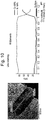
- FIG. 10 shows a result of measuring respective concentration variations of No, Co, and Al from the surface of a secondary particle of the positive active material, which is manufactured through Embodiment 4, toward the center of the particle.
- the positive active material manufactured through Embodiment 4 of the inventive concept has Co concentration that becomes higher toward the center from the surface in the Co-coated layer where Co is coated, but after the Co-coated layer, the Co concentration turns to be reduced as close as the center and a thickness of the Co-coated layer is 0.14 ⁇ m.
- FIG. 11 shows a result of measuring respective concentration variations of No, Co, and Al from three spots on the surface of a secondary particle of the positive active material, which is manufactured through Embodiment 4, toward the center of the secondary particle.
- FIG. 12 shows a result of measuring respective diffraction patterns and interplanar distances of primary particle locating in the internal part of the secondary particle of the positive active material manufactured through Embodiment 4 and locating on the surface part where Co and Ti are coated.
- a thickness of the Co-coated layer was about 140 nm
- a diffraction pattern of the primary particle locating in the internal part of the secondary particle was in a hexagonal structure
- interplanar distance of the primary particle locating in the internal part of the secondary particle was measured as 4.85 nm
- the primary particle locating on the surface part, which was coated with Co and Ti had a diffraction pattern of hexagonal structure but its interplanar distance thereof was measured as 4.69 nm.
- FIG. 13 shows a result of measuring a diffraction pattern and interplanar distances from a boundary between the inside of a primary particle, which locates on the surface part of a secondary particle of the positive active material manufactured through Embodiment 4, and a coated layer in the primary particle locating on the surface part of the secondary particle.
- the diffraction pattern was in a hexagonal structure and the interplanar distances were measured as 4.71 nm on average.
- FIG. 14 shows diffraction patterns and interplanar distances at boundaries of a primary particle locating on the surface part of a secondary particle, which is coated with Co and Ti, of the positive active material manufactured through Embodiment 4.
- the diffraction patterns are in a hexagonal structure and the interplanar distances are measured as 4.69 nm and 4.71 nm as an intermediate value of interplanar distances between a core part, that is internal part and a coated layer part.
- a positive active material of Embodiment 5 was manufactured by manufacturing a lithium secondary battery positive active material, which had been processed through the first thermal treatment, in the composition of Li 1.02 Ni 0.816 Co 0.15 Al 0.034 O 2 without addition of Ti.
- a positive active material of Embodiment 6 was manufactured by manufacturing a lithium secondary battery positive active material, which had been processed through the first thermal treatment, in the composition of Li 1.02 Ni 0.903 Co 0.08 Al 0.014 Mg 0.003 O 2 .
- a positive active material of Embodiment 7 was manufactured by manufacturing a lithium secondary battery positive active material, which had been processed through the first thermal treatment, in the composition of Li 1.00 Ni 0.965 Co 0.02 Al 0.014 Mg 0.001 O 2 .
- a positive active material of Embodiment 8 was manufactured by executing a coating process with 4 mol% concentration of a cobalt solution which was added to the positive active material washing liquid.
- a positive active material of Embodiment 9 was manufactured by executing a coating process with 5 mol% concentration of a cobalt solution which was added to the positive active material washing liquid.
- a positive active material of Embodiment 10 was manufactured by manufacturing a lithium secondary battery positive active material, which had been processed through the first thermal treatment, in the composition of Li 1.00 Ni 0.985 Al 0.014 Mg 0.001 O 2 .
- a positive active material of Comparison 2 was manufactured by injecting active material particles into a 0.1 mol cobalt solution, coating the active material with cobalt while agitating the mixture, and drying the coated material.
- FIG. 15 shows a result of measuring TEM and EDX photographs from the surface of a secondary particle of the positive active material manufactured through Comparison 2.
- the positive active material resulted in an uneven surface, without being doped into the inside, because there was no subsequent thermal treatment even though the Co distribution was concentrated on the surface due to the agitation with the active material particles which were injected into the cobalt solution.
- a positive active material of Comparison 4 was manufactured by adding Ti with concentration of 0.001 mol and then executing a second thermal treatment.
- a positive active material of Comparison 6 was prepared by manufacturing a lithium secondary battery positive active material, which had been processed through a first thermal treatment, in the composition of Li 1.00 Ni 0.815 Co 0.15 Al 0.014 O 2 .
- a positive active material of Comparison 7 was prepared by manufacturing a lithium secondary battery positive active material, which had been processed through a first thermal treatment, in the composition of Li 1.02 Ni 0.903 Co 0.08 Al 0.014 Mg 0.003 O 2 .
- a positive active material of Comparison 8 was prepared by manufacturing a lithium secondary battery positive active material, which had been processed through a first thermal treatment, in the composition of Li 1.00 Ni 0.965 Co 0.02 Al 0.014 Mg 0.001 O 2 .
- a positive active material of Comparison 9 was prepared by manufacturing a lithium secondary battery positive active material, which had been processed through a first thermal treatment, in the composition of Li 1.00 Ni 0.985 Al 0.014 Mg 0.001 O 2 .
- FIG. 16 shows a result of measuring TEM and EDX photographs from the surface of a secondary particle of the positive active material manufactured through Comparison 4.
- the positive active material manufactured through Comparison 4 has Co concentration uniformly distributed in the particle, because a Co coating process is not preformed after manufacturing an active material, and a Co concentration grade toward the inside of the particle is not found on the surface.
- FIG. 17 shows a result of measuring respective a diffraction pattern and interplanar distances from the surface of a secondary particle of the positive active material manufactured through Embodiment 4.
- a diffraction pattern of the surface was in a hexagonal structure and the interplanar distances were measured as 4.85 nm on average.
- FIG. 18 shows a result of measuring a diffraction pattern and interplanar distances of a primary particle locating in the internal part of the secondary particle of the positive active material manufactured through Comparison 4.
- the primary particle locating in the internal part of the secondary particle of the positive active material has a diffraction pattern of hexagonal structure and interplanar distances of 4.83 nm on average. It can be also seen that, even with a second thermal treatment in the case without a Co coating process, the interplanar distance of the primary particle locating in the internal part of the secondary particle of the positive active material is almost similar to that of a primary particle locating on the surface part of the secondary particle.
- FIG. 19 shows a result of measuring diffraction patterns and interplanar distances from a boundary of a primary particle locating on the surface part of a secondary particle of the positive active material manufactured through Embodiment 4.
- the primary particle locating on the surface part of the secondary particle of the positive active material was measured as having a diffraction pattern of hexagonal structure and interplanar distances of 4.81 nm on average.
- FIGS. 18 and 19 it can be seen from FIGS. 18 and 19 that, in the case without a Co coating process, diffraction patterns and interplanar distances are similar between the inside and the boundary of the primary particle.
- FIG. 20 shows a result of measuring respective concentration of Ni, Co, and Al toward the core from the surface of a secondary particle of the positive active material manufactured through Comparison 4.
- the positive active material manufactured through Comparison 4 has constant concentration of Ni, Co, and Al in the particle.
- FIG. 21 shows a result of measuring respective concentration of Ni, Co, and Al in a direction horizontal to the surface direction of a primary particle locating on the surface part of a secondary particle of the positive active material manufactured through Comparison 4.
- the positive active material manufactured through Comparison 4 has uniform concentration of Ni, Co, and Al in the particle, without a Co concentration grade due to absence of a CO coating process, and interplanar distances thereof are also similar between the surface part and the internal part
- FIG. 24 A result of measuring XRD for a positive active material of Comparison 2 is shown in FIG. 24 .
- FIG. 25 shows a result of measuring XRD for positive active materials manufactured through Comparison 4, which does not execute a Co coating process, and through Embodiment 4 executing a thermal treatment after a Co coating process.
- FIG. 26 shows results of measuring XPS for positive active materials manufactured through Comparison 4, which does not execute a Co coating process, and through Embodiment 3 executing a coating process with a cobalt solution which has concentration of 5 mol%.
- Slurry was manufactured by mixing the positive active materials, which were manufactured through Embodiments 1 to 10 and Comparisons 4, and 6 to 9, super-P as a conducting agent, and polyvinylidenefluoride (PVdF) as a binding agent in weight ratio of 92:5:3. Then an anode for a lithium secondary battery was manufactured by uniformly coating the slurry on an aluminum foil which has a thickness of 15 ⁇ m, and then by drying the slurry-coated aluminum foil at 135 °C under vacuum.
- PVdF polyvinylidenefluoride
- a coin battery was manufactured by using the anode and a lithium foil as the other electrode, using a porous polyethylene film (Celgard 2300 made by Celgard LLC; thickness of 25 ⁇ m) as a separator, and using a liquid electrolyte in which LiPF6 with concentration of 1.15 M was dissolved in a solvent in which ethylene carbonate and ethylmethyl carbonate are mixed in a volume ratio of 3:7.
- a porous polyethylene film (Celgard 2300 made by Celgard LLC; thickness of 25 ⁇ m) as a separator
- LiPF6 with concentration of 1.15 M was dissolved in a solvent in which ethylene carbonate and ethylmethyl carbonate are mixed in a volume ratio of 3:7.
- FIG. 27A Embodiments 1 to 4, Comparison 4
- FIG. 27B Embodiment 5, Comparison 6
- FIG. 27C Embodiment 6, Comparison 7
- FIG. 27D Embodiments 7 to 9, Comparison 8
- FIG. 27E Embodiment 10, Comparison 9
- the coating process executed according to the embodiments of the inventive concept contributed to the characteristics of capacity and efficiency that was measured as being more improved than that of a comparison examples.
- Embodiment 1 242.2 215.9 89.1 Embodiment 2 239.9 214.4 89.4 Embodiment 3 239.0 215.0 90.0 Embodiment 4 231.7 215.2 92.9 Embodiment 5 213.9 194.1 90.8 Embodiment 6 232.5 213.7 91.9 Embodiment 7 248.9 222.3 89.3 Embodiment 8 247.2 222.5 90.0 Embodiment 9 245.1 220.9 90.1 Embodiment 10 251.8 221.6 88.0 Comparison 4 244.5 209.7 85.8 Comparison 6 217.1 190.2 87.6 Comparison 7 239.3 211.3 88.3 Comparison 8 255.1 219.0 85.9 Comparison 9 258.2 221.6 85.8
- FIG. 28A Embodiments 1 to 4, Comparison 4
- FIG. 28B Embodiment 5, Comparison 6
- FIG. 28C Embodiment 6, Comparison 7
- FIG. 28D Embodiments 7 to 9, Comparison 8
- FIG. 28E Embodiment 10, Comparison 9
- the coating process executed by the embodiments of the inventive concept contributed to making the characteristics of capacity and efficiency measured as being more improved than the comparison examples.
- FIG. 29A Embodiments 1 to 4, Comparison 4
- FIG. 29C Embodiment 5, Comparison 6
- FIG. 29C Embodiment 6, Comparison 7
- FIG. 29D Embodiments 7 to 9, Comparison 8
- FIG. 29E Embodiment 10, Comparison 9
- the coating process executed according to the embodiments of the inventive concept contributed to making the characteristics of lifetime measured as being more improved than the comparison examples.
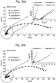
- FIG. 30A Embodiments 1 to 3, Comparison 4
- FIG. 30B Embodiment 5, Comparison 6
- FIG. 30C Embodiment 6, Comparison 7
- FIG. 30D Embodiments 7 to 9, Comparison 8
- FIG. 30E Embodiment 10, Comparison 9
- FIG. 31A Embodiments 1 to 3, Comparison 4
- FIG. 31B Embodiment 5, Comparison 6
- FIG. 31C Embodiment 6, Comparison 7
- FIG. 31D Embodiments 7 to 9, Comparison 8
- FIG. 31E Embodiment 10, Comparison 9
- the coating process executed by the embodiments of the inventive concept contributed to greatly improving the high temperature storage characteristics because impedances after high temperature storage increased less than those of the comparison examples.
- a secondary battery which includes a lithium complex oxide
- a secondary battery which includes a lithium complex oxide
- it may be allowable to improve a secondary battery, which includes a lithium complex oxide, in the characteristics of capacity, resistance, and lifetime with different interplanar distances of crystalline structures between the surface of a secondary particle and the inside of the secondary particle through washing and different metal coating processes for the lithium complex oxide.
Abstract
Description
- A claim for priority under 35 U.S.C. § 119 is made to Korean Patent Application No.
10-2016-0098647 filed August 2, 2016 10-2016-0130565 filed October 10, 2016 - Embodiments of the inventive concept described herein relate to a lithium complex oxide for a secondary battery and a method of preparing the same, and more particularly, relate to a lithium complex oxide for a secondary battery, and a method of preparing the same, improving the characteristics of capacity, resistance, and battery lifetime with different interplanar distances of crystalline structure between a primary particle locating on the surface of a secondary particle and a primary particle locating in the secondary particle by coating different elements on the surface, in consideration of inclination to functional degradation but reduction of residual lithium after a washing for removing the residual lithium in a preparation process, for a positive active material where lithium ion pathways in a-axis and c-axis of a crystalline structure.
- With an increase of technology and demand for mobile devices, secondary batteries as energy sources are increasing in demand. Among secondary batteries, lithium (Li) secondary batteries are being now commercialized and widely used on the merits of high energy density and operating potential, long cycle lifetime, and low discharge rate.
- A positive active material for a lithium secondary battery usually employs a lithium-contained cobalt oxide (LiCoO2). It is also considered therefor even to use a lithium-contained manganese oxide such as layered crystalline structure of LiMnO2 or spinel crystalline structure of LiMn2O4, or a lithium-contained nickel oxide such as LiNiO2.
- Among those positive active materials, LiCoO2 is most frequently used because of good characteristics of battery lifetime and charge/discharge efficiency, but there is a limit to competitiveness of cost in mass use as power sources for middle/large-scale batteries of electric vehicles because cobalt (Co) is rare and expensive as a resource, and small in capacity. Although the lithium manganese oxide such as LiMnO2 or LiMn2O4, as the positive active material, is low in price, eco-friendly, and highly stable in heat, it is deteriorative in high temperature and cycle characteristics.
- A method of preparing a lithium complex oxide generally includes the steps of manufacturing transition metal precursors, mixing a lithium compound and the transition metal precursors, and then baking the mixture. During this, LiOH and/or Li2CO3 are/is used for the lithium compound. It is generally preferred to use Li2CO3 in the case that Ni content of the positive active material is equal to or lower than 65% and preferred to use LiOH in the case that Ni content of the positive active material is equal to or higher than 65%.
- However, a nickel (Ni) rich system containing nickel equal to or higher than 65%, reactive at a low temperature, has a problem of having much residual lithium which remains in a form of LiOH and Li2CO3 on the surface of a positive active material. The residual lithium, that is, unreacted LiOH and Li2CO3 generate gas and a swelling effect by reacting with an electrolyte in the battery, and then cause high temperature stability to be seriously worse. Additionally, the unreacted LiOH also causes gelation because its viscosity is high when mixing slurry before manufacturing electrode plates.
- To remove such unreacted Li, a washing process is executed generally after preparing a positive active material, thereby much reducing residual lithium. However, during the washing process, the surface of the positive active material was damaged and degraded in characteristics of capacity and efficiency. Additionally, there was another problem to increase resistance in high temperature storage. Therefore, it is necessary to improve the characteristics of capacity, efficiency, and battery lifetime as well as to reduce residual lithium.
- Embodiments of the inventive concept provide a lithium complex oxide of a new structure improving the characteristics of capacity, resistance, and battery lifetime as well as reducing residual lithium.
- According to an aspect of the inventive concept, A lithium complex oxide secondary particle formed by coagulation of a plurality of primary particles includes a surface part of the secondary particle having a graded Co concentration; and an internal part of the secondary particle having constant Co concentration.
- In the lithium complex oxide secondary particle according to the inventive concept, a thickness of a surface part of the secondary particle having a graded Co concentration may be 50 to 150 nm.
- In the lithium complex oxide secondary particle according to the inventive concept, Co concentration may be graded in 0.05 to 0.07 mol% per one nm toward a center of the secondary particle.
- In the lithium complex oxide secondary particle according to the inventive concept, a primary particle locating on the surface part of the secondary particle may be configured to satisfy that dc/dh is 2 to 10, where the dc is a length toward a center and the dh is a length vertical to the center. That is, primary particles forming the surface part of the secondary particle according to the inventive concept may be shaped in an oval or stick that has an aspect ratio of 2 to 10.
- In the lithium complex oxide secondary particle according to the inventive concept, the secondary particle may have at least one peak at positions (104), (110), (113), (101), (102), and (003) during XRD analysis. The peak appearing at (104), (110), (113), (101), (102), or (003) may be a specific peak generated from LiCoO2, lithium complex oxide secondary particle according to the inventive concept may generate such a specific peak by coated different metals during a Co-coating with the different metals after a washing process.
- In the lithium complex oxide secondary particle according to the inventive concept, the secondary particle may have a bound energy (P1) of spin-orbit-spit 2p3/2 peak and a bound energy (P2) of 2p1/2 peak in a
Co 2p core-level spectrometry obtained through XPS measurement, wherein the P1 and the P2 may be ranged respectively in 779eV≤P1≤780eV and 794eV≤P2≤795eV. - In the lithium complex oxide secondary particle according to the inventive concept, the secondary particle may have a ratio of peak intensity (I531) around 531 eV and peak intensity (I528) around 528.5 eV during an
O 1s core-level spectrometry that is obtained through XPS measurement, wherein the ratio may be I531/I528≤2. - In the lithium complex oxide secondary particle according to the inventive concept, the secondary particle has a ratio between peak intensity (I289) around 289 eV and peak intensity (I284) around 284.5 eV during a
C 1s core-level spectrometry that is obtained through XPS measurement, wherein the ratio is I289/I284≤0.9. - In the lithium complex oxide secondary particle according to the inventive concept, the secondary particle may be given by the following
Formula 1, [Formula 1]LiX1Ni1-(x1+y1+z1)Cox1M1y1M2z1M3r1Oa, wherein, in theFormula 1, M1 may be Mn or Al, and M2 and M3 are metals selected from a group of Al, Ba, B, Co, Ce, Cr, F, Li, Mg, Mn, Mo, P, Sr, Ti, and Zr, and wherein 0.95≤X1≤1.05, 1.50≤a≤2.1, 0.02≤x1≤0.25, 0.01≤y1≤0.20, 0≤z≤0.20, and 0≤r1≤0.20. - According to another aspect of the inventive concept, a method of preparing a lithium complex oxide secondary particle may include manufacturing precursors of lithium secondary battery positive active materials given by the following Formula 2, [Formula 2]Ni1-(x2+y2+z2)Cox2M1y2M2z2(OH)2, wherein, in Formula 2, M1 is Mn or Al, and M2 is a metal selected from a group of Al, Ba, B, Co, Ce, Cr, F, Li, Mg, Mn, Mo, P, Sr, Ti, and Zr, and wherein 0≤x2≤0.25, 0≤y2≤0.20, and 0≤z2≤0.20, reacting precursors of lithium secondary battery positive active materials with a lithium compound and manufacturing a positive active material by first thermal treating the reactant, washing the positive active material with distilled water or an alkaline solution, reactively coating the washed positive active material with a solution containing M2 that is a metal selected from the group of Al, Ba, B, Co, Ce, Cr, F, Li, Mg, Mn, Mo, P, Sr, Ti, and Zr, drying particles of the positive active material, and mixing the dried positive active material with M3 that is a metal selected from the group of Al, Ba, B, Co, Ce, Cr, F, Li, Mg, Mn, Mo, P, Sr, Ti, and Zr and doping the metal M3 into the particles by second thermal treating the mixture.
- In the method of preparing a lithium complex oxide secondary particle according to the inventive concept, the reactively coating may include reactively coating the washed positive active material with the solution containing Co ion.
- In the method of preparing a lithium complex oxide secondary particle according to the inventive concept, in the reactively coating, a thickness of a surface part of the secondary particle having a graded Co concentration varies according to the solution containing Co ion.
- According to still another aspect of the inventive concept, a lithium secondary battery includes a lithium complex oxide secondary particle prepared according to embodiments of the inventive concept.
- The lithium secondary battery according to the inventive concept may be configured to have residual lithium equal to or smaller than 6,000 ppm.
- The above and other objects and features will become apparent from the following description with reference to the following figures, wherein like reference numerals refer to like parts throughout the various figures unless otherwise specified, and wherein:
-
FIG. 1 shows a result of measuring diffraction patterns and interplanar distances of an LiCoO2 positive active material ofComparison 1 according to the inventive concept; -
FIG. 2 shows a result of measuring TEM and EDX photographs of a positive active material prepared according to an embodiment of the inventive concept; -
FIG. 3 shows a result of measuring diffraction patterns and interplanar distances of a positive active material prepared according to an embodiment of the inventive concept; -
FIG. 4 shows a result of measuring TEM and EDX photographs of a positive active material prepared according to an embodiment of the inventive concept; -
FIG. 5 shows a result of measuring diffraction patterns and interplanar distances of a positive active material prepared according to an embodiment of the inventive concept; -
FIG. 6 shows a result of measuring respective variations of concentration for Ni, Co, and Al toward the center from the surface of a positive active material prepared according to an embodiment of the inventive concept; -
FIG. 7 shows a result of measuring an EDX photograph of a positive active material prepared according to an embodiment of the inventive concept; -
FIG. 8 shows a result of measuring diffraction patterns and interplanar distances of a positive active material prepared according to an embodiment of the inventive concept; -
FIG. 9 shows a result of measuring TEM and EDX photographs of a positive active material prepared according to an embodiment of the inventive concept; -
FIG. 10 shows a result of measuring respective variations of concentration for Ni, Co, and Al toward the center from the surface of a positive active material prepared according to an embodiment of the inventive concept; -
FIG. 11 shows a result of measuring respective variations of concentration for Ni, Co, and Al toward the center from a third spot of a positive active material prepared according to an embodiment of the inventive concept; -
FIGS. 12 to 14 show results of measuring diffraction patterns and interplanar distances of positive active materials manufactured by comparison examples and embodiments of the inventive concept; -
FIGS. 15 and16 show results of measuring EDX photographs of positive active materials manufactured by comparison examples of the inventive concept; -
FIGS. 17 to 19 show results of measuring diffraction patterns and interplanar distances of positive active materials manufactured by comparison examples and embodiments of the inventive concept; -
FIGS. 20 and21 show results of measuring respective variations of concentration for Ni, Co, and Al toward the center from the surface of a positive active material prepared according to an embodiment of the inventive concept; -
FIGS. 22 to 25 show results of measuring XRD of positive active materials manufactured by comparison examples and embodiments of the inventive concept; -
FIG. 26 shows a result of measuring XPS of positive active materials manufactured by a comparison example and an embodiment of the inventive concept; and -
FIGS. 27A to 31E show results of measuring the characteristics of batteries including positive active materials manufactured by comparison examples and embodiments of the inventive concept. - Hereafter, embodiments of the inventive concept will be described in detail with reference to the accompanying figures. The inventive concept may not be however restrictive to the embodiments proposed below.
- A LiCoO2 positive active material, which is commercially sold, was used for Comparison 1.
-
FIG. 1 shows respective diffraction patterns and interplanar distances for a primary particle, which locates in the internal part of the secondary particle, and a primary particle locating on the surface part of the secondary particle of the LiCoO2 positive active material ofComparison 1. - After mounting the LiCoO2 positive active material on a carbon grid, coating the LiCoO2 positive active material with carbon and PT, and then magnifying the coated LiCoO2 positive active material in 20 million or 25 million times through a TEM pre-treatment that slices the coated LiCoO2 positive active material, ten interplanar distances were measured left and light around an interplanar distance to be known.
- As shown in
FIG. 1 , diffraction patterns of the primary particles locating in the internal part of the secondary particle of the LiCoO2 positive active material and locating on the surface part of the secondary particle were all in hexagonal structure, and interplanar distances of the primary particles locating in the internal part of the secondary particle and locating on the surface part of the secondary particle were all measured as 4.70 nm. - First, NiCo(OH)2 precursors were manufactured through a coprecipitation. Then, a lithium secondary battery positive active material was manufactured by adding Li2CO3 and LiOH as lithium compounds to the manufactured precursors, adding Al and Mg as M1 thereto, and processing the mixture in first thermal treatment.
- After preparing distilled water, the manufactured lithium secondary battery positive active material was washed by injecting the distilled water in uniform temperature.
- Afterward, the surface of the positive active material was washed and coated with Co as M2 by agitating the positive active material while injecting a cobalt sulfate solution of 0.03 mol into the positive active material washing liquid for one hour in a specific ratio, and then dried at 120°C under a vacuum.
- Then, the lithium secondary battery positive active material was manufactured by adding Ti as M3 to the coated positive active material and processing the Ti-added positive active material in second thermal treatment at 450 °C.
- TEM and EDX photographs were taken from the positive active material manufactured through
Embodiment 1 and shown inFIG. 2 . - As shown in
FIG. 2 , the positive active material manufactured throughEmbodiment 1 of the inventive concept has Co concentration that is higher on the surface of the secondary particle and lower toward the inside from the surface of the secondary particle. Co concentration is ununiform in the secondary particle with a grade. -
FIG. 3 shows respective diffraction patterns and interplanar distances for primary particles locating in the secondary particle manufactured throughEmbodiment 1 and locating on the surface on which Co and Ti are coated. - As shown in
FIG. 3 , the thickness of a Co-coated layer is about 80 nm, and the diffraction pattern of the primary particle locating in the secondary particle is in hexagonal structure. For the primary particle locating in the secondary particle, 10 adjacent interplanar distances were measured as 4.88 nm on average in a TEM photograph. Comparatively, the primary particle locating on the surface having the Co-coated layer was measured as exhibiting a diffraction pattern of hexagonal structure with an interplanar distance of 4.73 nm. - From this result, it can be seen that the interplanar distance of the primary particle locating on the surface was relatively reduced in comparison with the primary particle locating in the secondary particle which was not coated with cobalt, and the interplanar distance of the primary particle locating on the surface was changed similar to an interplanar distance of LiCoO2 of a comparison example.
- A positive active material of
Embodiment 2 was manufactured in the same asEmbodiment 1, except that concentration of a cobalt solution added to the positive active material washing liquid is 4 mol%. -
FIG. 4 shows a result of measuring TEM and EDX photographs of the positive active material manufactures throughEmbodiment 2. - As shown in
FIG. 4 , it can be seen that the positive active material manufactured throughEmbodiment 2 of the inventive concept has Co concentration that is higher on the surface of the secondary particle and lower toward the inside of the secondary particle. That is, Co concentration of the positive active material is ununiform and distributed in a grade. -
FIG. 5 shows a result of measuring respective diffraction patterns and interplanar distances of primary particles locating in the positive active material manufactured throughEmbodiment 1 and locating on the surface where Co and Ti are coated. - As shown in
FIG. 5 , it was measured that a thickness of the Co-coated layer was about 90 nm, a diffraction pattern of the primary particle locating in a secondary particle was in a hexagonal structure, and an average of 10 adjacent interplanar distances of the primary particle locating in the secondary particle was measured as 4.85 nm in a TEM photograph, while the primary particle locating on the surface of the Co-coated layer had a diffraction pattern of hexagonal structure but an interplanar distance thereof was measured as 4.73 nm. - It can be seen that, comparative to the primary particle locating in the Co-uncoated secondary particle, the interplanar distance of the primary particle locating on the surface part was reduced and changed similar to the interplanar distance of LiCoO2 of a comparison example.
- In the same manner with
Embodiment 1, a positive active material ofEmbodiment 3 was manufactured by executing a coating process with 5 mol% concentration of a cobalt solution added to the positive active material washing liquid. -
FIG. 6 shows a result of measuring respective concentration variations of No, Co, and Al from the surface of the secondary particle of the positive active material, which is manufactured throughEmbodiment 3, toward the center of the particle. - From
FIG. 6 , it can be seen that the positive active material manufactured throughEmbodiment 3 of the inventive concept has Co concentration that becomes higher toward the center from the surface in the Co-coated layer where Co is coated, but after the Co-coated layer, the Co concentration turns to be reduced as close as the center and a thickness of the Co-coated layer is 0.1 µm. -
FIG. 7 shows a result of measuring respective EDX photographs for Ni, Co, and Al from the surface of the secondary particle of the positive active material, which is manufactured throughEmbodiment 3, toward the center of the particle. - From
FIG. 7 , it can be seen that the positive active material manufactured throughEmbodiment 3 of the inventive concept has Co concentration that becomes higher toward the center from the surface in the Co-coated layer where Co is coated, but after the Co-coated layer, the Co concentration turns to be reduced as close as the center and concentration of the Co-coated layer is higher along the boundaries of the primary particles. -
FIG. 8 shows a result of measuring respective diffraction patterns and interplanar distances of primary particles locating in the internal part of the positive active material manufactured throughEmbodiment 3 and locating on the surface part on which Co and Ti are coated. - As shown in
FIG. 8 , it was measured that a thickness of the Co-coated layer was about 100 nm, a diffraction pattern of the primary particle locating in the internal part of the secondary particle was in a hexagonal structure, and an average of 10 adjacent interplanar distances of the primary particle locating in the internal part of the secondary particle was measured as 4.84 nm in a TEM photograph, while the primary particle locating on the Co-coated layer had a diffraction pattern of hexagonal structure but an interplanar distance thereof was measured as 4.67 nm. - It can be seen that, comparative to the primary particle locating in the Co-uncoated secondary particle, the interplanar distance of the primary particle locating on the Co-coated surface was reduced and changed similar to interplanar distances of LiCoO2 of a comparison example.
- In the same manner with
Embodiment 1, a positive active material ofEmbodiment 4 was manufactured by executing a washing and coating process with 10 mol% concentration of a cobalt solution added to the positive active material washing liquid. -
FIG. 9 shows a result of measuring TEM and EDX photographs on the surface part of the secondary particle of the positive active material manufactured throughEmbodiment 4. - As shown in
FIG. 9 , it can be seen that the positive active material manufactured throughEmbodiment 4 of the inventive concept has Co concentration that becomes higher on the surface of the secondary particle but turns to be lower as close as the center of the secondary particle. Thus, the Co concentration is ununiform in a grade. - Additionally, the EDX measurement shows a Co distribution of bar-shaped primary particle, from which it can be seen that Co concentration is measured as being higher at the periphery of the bar-shaped primary particle.
-
FIG. 10 shows a result of measuring respective concentration variations of No, Co, and Al from the surface of a secondary particle of the positive active material, which is manufactured throughEmbodiment 4, toward the center of the particle. - From
FIG. 10 , it can be seen that the positive active material manufactured throughEmbodiment 4 of the inventive concept has Co concentration that becomes higher toward the center from the surface in the Co-coated layer where Co is coated, but after the Co-coated layer, the Co concentration turns to be reduced as close as the center and a thickness of the Co-coated layer is 0.14 µm. -
FIG. 11 shows a result of measuring respective concentration variations of No, Co, and Al from three spots on the surface of a secondary particle of the positive active material, which is manufactured throughEmbodiment 4, toward the center of the secondary particle. - From
FIG. 11 , it can be seen that three independent spots on the surface of the secondary particle of the positive active material manufactured throughEmbodiment 4 have thicknesses of 0.14 µm that forms a uniform grade therein. -
FIG. 12 shows a result of measuring respective diffraction patterns and interplanar distances of primary particle locating in the internal part of the secondary particle of the positive active material manufactured throughEmbodiment 4 and locating on the surface part where Co and Ti are coated. - As shown in
FIG. 12 , it was measured that a thickness of the Co-coated layer was about 140 nm, a diffraction pattern of the primary particle locating in the internal part of the secondary particle was in a hexagonal structure, and interplanar distance of the primary particle locating in the internal part of the secondary particle was measured as 4.85 nm, while the primary particle locating on the surface part, which was coated with Co and Ti, had a diffraction pattern of hexagonal structure but its interplanar distance thereof was measured as 4.69 nm. - It can be seen that, comparative to the primary particle locating in the Co-uncoated secondary particle, the interplanar distance of the primary particle locating on the Co-coated surface was reduced and changed similar to the interplanar distance of LiCoO2 of a comparison example.
-
FIG. 13 shows a result of measuring a diffraction pattern and interplanar distances from a boundary between the inside of a primary particle, which locates on the surface part of a secondary particle of the positive active material manufactured throughEmbodiment 4, and a coated layer in the primary particle locating on the surface part of the secondary particle. - As shown in
FIG. 13 , from the boundary between the inside of the primary particle, which locates on the surface part of the secondary particle of the positive active material manufactured throughEmbodiment 4, and the coated layer, which is coated with Co and Ti, in the primary particle locating on the surface part of the secondary particle, the diffraction pattern was in a hexagonal structure and the interplanar distances were measured as 4.71 nm on average. - It can be seen that, comparative to the primary particle locating in the internal part of the secondary particle has an interplanar distance of 4.85 nm and the primary particle locating on the surface part of the secondary particle, which is coated with Co and Ti, has an interplanar distance of 4.69 nm, the interplanar distance of the coated layer boundary in the primary particle locating on the surface of the secondary particle coated with Co and Ti, that is, 4.71 nm, was measured as an intermediate value between the interplanar distance of the primary particle locating in the internal part of the secondary particle and the interplanar distance of the primary particle locating on the surface part of the secondary particle which is coated with Co and Ti.
- Additionally, it can be seen that the interplanar distance of the primary particle at the coated layer boundary was changed similar to the interplanar distance of LiCoO2 of a comparison example.
-
FIG. 14 shows diffraction patterns and interplanar distances at boundaries of a primary particle locating on the surface part of a secondary particle, which is coated with Co and Ti, of the positive active material manufactured throughEmbodiment 4. - As shown in
FIG. 14 , from the boundaries of the primary particle locating on the surface part of the secondary particle of the positive active material, the diffraction patterns are in a hexagonal structure and the interplanar distances are measured as 4.69 nm and 4.71 nm as an intermediate value of interplanar distances between a core part, that is internal part and a coated layer part. - Additionally, it can be seen that the interplanar distance of the primary particle at the coated layer boundary was changed similar to the interplanar distance of LiCoO2 of a comparison example.
- In the same manner with
Embodiment 1, a positive active material ofEmbodiment 5 was manufactured by manufacturing a lithium secondary battery positive active material, which had been processed through the first thermal treatment, in the composition of Li1.02Ni0.816Co0.15Al0.034O2 without addition of Ti. - In the same manner with
Embodiment 1, a positive active material ofEmbodiment 6 was manufactured by manufacturing a lithium secondary battery positive active material, which had been processed through the first thermal treatment, in the composition of Li1.02Ni0.903Co0.08Al0.014Mg0.003O2. - In the same manner with
Embodiment 1, a positive active material ofEmbodiment 7 was manufactured by manufacturing a lithium secondary battery positive active material, which had been processed through the first thermal treatment, in the composition of Li1.00Ni0.965Co0.02Al0.014Mg0.001O2. - In the same manner with
Embodiment 7, a positive active material ofEmbodiment 8 was manufactured by executing a coating process with 4 mol% concentration of a cobalt solution which was added to the positive active material washing liquid. - In the same manner with
Embodiment 7, a positive active material ofEmbodiment 9 was manufactured by executing a coating process with 5 mol% concentration of a cobalt solution which was added to the positive active material washing liquid. - In the same manner with
Embodiment 7, a positive active material ofEmbodiment 10 was manufactured by manufacturing a lithium secondary battery positive active material, which had been processed through the first thermal treatment, in the composition of Li1.00Ni0.985Al0.014Mg0.001O2. - The final formulas of compositions used in
Embodiments 1 to 10 are summarized in Table 1 as follows.[Table 1] Final Composition Formula LiX1Ni1-(x1+y1+z1)Cox1M1y1M2z1M3r1Oa Embodiment 1 Li1.01Ni0.903Co0.08Al0.015Mg0.001Ti0.001O2 Embodiment 2 Li1.01Ni0.893Co0.09Al0.015Mg0.001Ti0.001O2 Embodiment 3 Li1.02Ni0.883Co0.10Al0.015Mg0.001Ti0.001O2 Embodiment 4 Li1.02Ni0.833Co0.10Al0.015Mg0.001Ti0.001O2 Embodiment 5 Li1.02Ni0.786Co0.18Al0.034O2 Embodiment 6 Li1.02Ni0.873Co0.11Al0.015Mg0.001Ti0.001O2 Embodiment 7 Li1.00Ni0.933Co0.05Al0.015Mg0.001Ti0.001O2 Embodiment 8 Li1.00Ni0.923Co0.06Al0.015Mg0.001Ti0.001O2 Embodiment 9 Li1.00Ni0.913Co0.07Al0.015Mg0.001Ti0.001O2 Embodiment 10 Li1.00Ni0.953Co0.03Al0.015Mg0.001Ti0.001O2 - In the same manner with
Embodiment 4, a positive active material ofComparison 2 was manufactured by injecting active material particles into a 0.1 mol cobalt solution, coating the active material with cobalt while agitating the mixture, and drying the coated material. - In the same manner with
Embodiment 4, a positive active material ofComparison 3 was manufactured, without including Co during a washing process, by excluding a Ti adding process and a second thermal treatment. -
FIG. 15 shows a result of measuring TEM and EDX photographs from the surface of a secondary particle of the positive active material manufactured throughComparison 2. - As shown in
FIG. 15 , it can be seen that the positive active material resulted in an uneven surface, without being doped into the inside, because there was no subsequent thermal treatment even though the Co distribution was concentrated on the surface due to the agitation with the active material particles which were injected into the cobalt solution. - In the same manner with
Comparison 3, a positive active material ofComparison 4 was manufactured by adding Ti with concentration of 0.001 mol and then executing a second thermal treatment. - In the same manner with
Comparison 3, a positive active material ofComparison 5 was prepared, without a washing process, after manufacturing a lithium secondary battery positive active material which had been processed through a first thermal treatment. - In the same manner with
Comparison 3, a positive active material ofComparison 6 was prepared by manufacturing a lithium secondary battery positive active material, which had been processed through a first thermal treatment, in the composition of Li1.00Ni0.815Co0.15Al0.014O2. - In the same manner with
Comparison 4, a positive active material ofComparison 7 was prepared by manufacturing a lithium secondary battery positive active material, which had been processed through a first thermal treatment, in the composition of Li1.02Ni0.903Co0.08Al0.014Mg0.003O2. - In the same manner with
Comparison 4, a positive active material ofComparison 8 was prepared by manufacturing a lithium secondary battery positive active material, which had been processed through a first thermal treatment, in the composition of Li1.00Ni0.965Co0.02Al0.014Mg0.001O2. - In the same manner with
Comparison 4, a positive active material ofComparison 9 was prepared by manufacturing a lithium secondary battery positive active material, which had been processed through a first thermal treatment, in the composition of Li1.00Ni0.985Al0.014Mg0.001O2. - The final formulas of compositions used in
Comparisons 1 to 9 are summarized in Table 2 as follows. - The final formulas of compositions used in the first thermal treatments of
Comparisons 1 to 9 are summarized in Table 2 as follows.[Table 2] Final Composition Formula LiX1Ni1-(x1+y1+z1)Cox1M1y1M2z1M3r1Oa Comparison 1 LiCoO2 Comparison 2 Washed and dried product of Embodiment 4Comparison 3Washed and dried product of Comparison 4Comparison 4Li1.00Ni0.933Co0.05Al0.015Mg0.001Ti0.001O2 Comparison 5 Li1.05Ni0.934Co0.05Al0.015Mg0.001Ti0.001O2 (Unwashed product) Comparison 6Li1.00Ni0.815Co0.15Al0.035O2 Comparison 7 Li1.02Ni0.903Co0.08Al0.015Mg0.001Ti0.001O2 Comparison 8 Li1.00Ni0.963Co0.02Al0.015Mg0.001Ti0.001O2 Comparison 9 Li1.00Ni0.983Co0.05Al0.015Mg0.001Ti0.001O2 -
FIG. 16 shows a result of measuring TEM and EDX photographs from the surface of a secondary particle of the positive active material manufactured throughComparison 4. - As shown in
FIG. 16 , it can be seen that the positive active material manufactured throughComparison 4 has Co concentration uniformly distributed in the particle, because a Co coating process is not preformed after manufacturing an active material, and a Co concentration grade toward the inside of the particle is not found on the surface. -
FIG. 17 shows a result of measuring respective a diffraction pattern and interplanar distances from the surface of a secondary particle of the positive active material manufactured throughEmbodiment 4. - As shown in
FIG. 17 , a diffraction pattern of the surface was in a hexagonal structure and the interplanar distances were measured as 4.85 nm on average. -
FIG. 18 shows a result of measuring a diffraction pattern and interplanar distances of a primary particle locating in the internal part of the secondary particle of the positive active material manufactured throughComparison 4. - As shown in
FIG. 18 , it can be seen that the primary particle locating in the internal part of the secondary particle of the positive active material has a diffraction pattern of hexagonal structure and interplanar distances of 4.83 nm on average. It can be also seen that, even with a second thermal treatment in the case without a Co coating process, the interplanar distance of the primary particle locating in the internal part of the secondary particle of the positive active material is almost similar to that of a primary particle locating on the surface part of the secondary particle. -
FIG. 19 shows a result of measuring diffraction patterns and interplanar distances from a boundary of a primary particle locating on the surface part of a secondary particle of the positive active material manufactured throughEmbodiment 4. - As shown in
FIG. 19 , the primary particle locating on the surface part of the secondary particle of the positive active material was measured as having a diffraction pattern of hexagonal structure and interplanar distances of 4.81 nm on average. - Additionally, it can be seen from
FIGS. 18 and19 that, in the case without a Co coating process, diffraction patterns and interplanar distances are similar between the inside and the boundary of the primary particle. -
FIG. 20 shows a result of measuring respective concentration of Ni, Co, and Al toward the core from the surface of a secondary particle of the positive active material manufactured throughComparison 4. - From
FIG. 20 , it can be seen that the positive active material manufactured throughComparison 4 has constant concentration of Ni, Co, and Al in the particle. -
FIG. 21 shows a result of measuring respective concentration of Ni, Co, and Al in a direction horizontal to the surface direction of a primary particle locating on the surface part of a secondary particle of the positive active material manufactured throughComparison 4. - From
FIG. 21 , it can be seen that the positive active material manufactured throughComparison 4 has uniform concentration of Ni, Co, and Al in the particle, without a Co concentration grade due to absence of a CO coating process, and interplanar distances thereof are also similar between the surface part and the internal part - Results of measuring XRD for LiCoO2 positive active materials of
Embodiment 4 andComparison 1 are shown inFIGS. 22 and23 . - As shown in
FIGS. 22 and23 , it can be seen that a Co and Ti coated positive active material, which is manufactured throughEmbodiment 4 of the inventive concept, is detected with peaks of (104), (110), (113), (101), (102), and (003) as like the case of LiCoO2 ofComparison 1. - A result of measuring XRD for a positive active material of
Comparison 2 is shown inFIG. 24 . - As shown in
FIG. 24 , it can be seen that the positive active material manufactured throughComparison 2 of the inventive concept is detected only with a peak by Co(OH)2 but there are no detection with peaks of (104), (110), (113), (101), (102), and (003). -
FIG. 25 shows a result of measuring XRD for positive active materials manufactured throughComparison 4, which does not execute a Co coating process, and throughEmbodiment 4 executing a thermal treatment after a Co coating process. - As shown in
FIG. 25 , it can be seen that the positive active material manufactured throughComparison 4, which does not execute the Co coating process of the inventive concept, is not detected with peaks of (104), (110), (113), (101), (102), and (003) that are distinctly detected from LiCoO2. -
FIG. 26 shows results of measuring XPS for positive active materials manufactured throughComparison 4, which does not execute a Co coating process, and throughEmbodiment 3 executing a coating process with a cobalt solution which has concentration of 5 mol%. - As shown in
FIG. 26 , it can be seen that, in the case of coating cobalt during a washing process according to the inventive concept, theCo 2p peak intensity is larger, almost due to Co+3, than that ofComparison 4. Additionally, it can be also seen that the peak intensity by Li2CO3 is more reduced than that ofComparison 4. - A result of measuring amounts of residual lithium from composite oxides manufactured through
Embodiments 1 to 10 andComparisons 4 to 9 is summarized in Table 3 as follows. - To measure residual lithium, an active material of 1g was precipitated in distilled water of 5g and agitated for 5 minutes. Next, filtrate was taken after the agitation and titration was executed with HCL of 0.1 M. Then, the residual lithium was analyzed by measuring a volume of the HCL until pH of the filtrate reaches 5.
- From Table 3, it can be seen that active materials manufactured through embodiments of the inventive concept have residual lithium which is greatly reduced relative to the case as like as
Comparison 5 that does not execute a thermal treatment.[Table 3] Residual Lithium (ppm) LiOH Li2CO3 Total Comparison 4 1043 1787 2830 Comparison 57516 9733 17249 Comparison 62628 987 3615 Comparison 71017 1686 3396 Comparison 81744 1622 3366 Comparison 91856 2212 4068 Embodiment 11506 1996 3502 Embodiment 21432 1971 3403 Embodiment 31562 1549 3111 Embodiment 42142 2450 4592 Embodiment 52556 862 3418 Embodiment 61730 1830 3560 Embodiment 71630 2166 3796 Embodiment 82035 2433 4468 Embodiment 91569 2067 3636 Embodiment 102519 1881 4400 - Slurry was manufactured by mixing the positive active materials, which were manufactured through
Embodiments 1 to 10 andComparisons - A coin battery was manufactured by using the anode and a lithium foil as the other electrode, using a porous polyethylene film (Celgard 2300 made by Celgard LLC; thickness of 25 µm) as a separator, and using a liquid electrolyte in which LiPF6 with concentration of 1.15 M was dissolved in a solvent in which ethylene carbonate and ethylmethyl carbonate are mixed in a volume ratio of 3:7.
- Results of measuring initial capacities of batteries manufactured with active materials manufactured through
Embodiments 1 to 10 andComparisons FIG. 27A (Embodiments 1 to 4, Comparison 4),FIG. 27B (Embodiment 5, Comparison 6),FIG. 27C (Embodiment 6, Comparison 7),FIG. 27D (Embodiments 7 to 9, Comparison 8), andFIG. 27E (Embodiment 10, Comparison 9). - Referring to
FIGS. 27A to 27E , the coating process executed according to the embodiments of the inventive concept contributed to the characteristics of capacity and efficiency that was measured as being more improved than that of a comparison examples. - Results of measuring initial capacities of batteries manufactured with active materials manufactured through
Embodiments 1 to 10 andComparisons [Table 4] 0.1C Charge/Discharge Charge (mAh/g) Discharge (mAh/g) 1st Eff. (%) Embodiment 1242.2 215.9 89.1 Embodiment 2239.9 214.4 89.4 Embodiment 3239.0 215.0 90.0 Embodiment 4231.7 215.2 92.9 Embodiment 5213.9 194.1 90.8 Embodiment 6232.5 213.7 91.9 Embodiment 7248.9 222.3 89.3 Embodiment 8247.2 222.5 90.0 Embodiment 9245.1 220.9 90.1 Embodiment 10251.8 221.6 88.0 Comparison 4244.5 209.7 85.8 Comparison 6217.1 190.2 87.6 Comparison 7239.3 211.3 88.3 Comparison 8255.1 219.0 85.9 Comparison 9258.2 221.6 85.8 - Results of measuring efficiency characteristics of batteries manufactured with active materials manufactured through
Embodiments 1 to 10 andComparisons FIG. 28A (Embodiments 1 to 4, Comparison 4),FIG. 28B (Embodiment 5, Comparison 6),FIG. 28C (Embodiment 6, Comparison 7),FIG. 28D (Embodiments 7 to 9, Comparison 8), andFIG. 28E (Embodiment 10, Comparison 9). - Referring to
FIGS. 28A to 28E , the coating process executed by the embodiments of the inventive concept contributed to making the characteristics of capacity and efficiency measured as being more improved than the comparison examples. - Results of measuring the efficiency characteristics of batteries manufactured with active materials manufactured through
Embodiments 1 to 10 andComparisons [Table 5] ITEM 0.1C 0.2C 0.5C 1.0C 1.5C 2.0 C Embodiment 1 100.0 % 97.6 % 94.2 % 91.8 % 90.2 % 89.2 % Embodiment 2 100.0 % 97.8 % 94.5 % 92.3 % 90.9 % 89.8 % Embodiment 3 100.0 % 97.7 % 94.6 % 92.3 % 90.7 % 89.6 % Embodiment 4 100.0 % 97.9 % 94.5 % 91.9 % 90.2 % 88.9 % Embodiment 5 100.0 % 98.9 % 95.2 % 92.2 % 90.4 % 89.0 % Embodiment 6 100.0 % 97.2 % 93.0 % 89.9 % 88.4 % 87.3 % Embodiment 7 100.0 % 96.9 % 93.1 % 90.2 % 88.4 % 86.8 % Embodiment 8 100.0 % 96.7 % 92.5 % 89.5 % 87.4 % 85.6 % Embodiment 9 100.0 % 97.0 % 93.2 % 90.5 % 88.8 % 87.4 % Embodiment 10 100.0 % 96.5 % 92.7 % 89.7 % 87.1 % 84.4 % Comparison 4 100.0 % 97.3 % 94.2 % 92.0 % 90.6 % 89.6 % Comparison 6 100.0 % 98.3 % 94.1 % 91.1 % 89.4 % 88.2 % Comparison 7 100.0 % 96.3 % 92.6 % 89.4 % 86.1 % 82.5 % Comparison 8 100.0 % 96.3 % 92.6 % 89.4 % 86.1 % 82.5 % Comparison 9 100.0 % 96.3 % 92.6% 89.3 % 85.9 % 82.3 % - Results of measuring lifetime characteristics of batteries manufactured with active materials manufactured through
Embodiments 1 to 10 andComparisons FIG. 29A (Embodiments 1 to 4, Comparison 4),FIG. 29C (Embodiment 5, Comparison 6),FIG. 29C (Embodiment 6, Comparison 7),FIG. 29D (Embodiments 7 to 9, Comparison 8), andFIG. 29E (Embodiment 10, Comparison 9). - Referring to
FIGS. 29A to 29E , the coating process executed according to the embodiments of the inventive concept contributed to making the characteristics of lifetime measured as being more improved than the comparison examples. - Results of measuring the lifetime characteristics of batteries manufactured with active materials manufactured through
Embodiments 1 to 10 andComparisons [Table 6] Room Temperature Lifetime 50th / 1st (%) Embodiment 177.4 Embodiment 280.4 Embodiment 378.9 Embodiment 474.9 Embodiment 589.5 Embodiment 655.0 Embodiment 754.6 Embodiment 861.4 Embodiment 963.3 Embodiment 1068.5 Comparison 477.5 Comparison 688.7 Comparison 755.0 Comparison 853.1 Comparison 963.0 - As results of measuring high temperature storage characteristics of batteries manufactured with active materials manufactured through
Embodiments 1 to 3 and 5 to 10, andComparisons FIG. 30A (Embodiments 1 to 3, Comparison 4),FIG. 30B (Embodiment 5, Comparison 6),FIG. 30C (Embodiment 6, Comparison 7),FIG. 30D (Embodiments 7 to 9, Comparison 8), andFIG. 30E (Embodiment 10, Comparison 9), and the results after storage are respectively shown inFIG. 31A (Embodiments 1 to 3, Comparison 4),FIG. 31B (Embodiment 5, Comparison 6),FIG. 31C (Embodiment 6, Comparison 7),FIG. 31D (Embodiments 7 to 9, Comparison 8), andFIG. 31E (Embodiment 10, Comparison 9). - Referring to
FIGS. 30A to 30E and31A to 31E , the coating process executed by the embodiments of the inventive concept contributed to greatly improving the high temperature storage characteristics because impedances after high temperature storage increased less than those of the comparison examples. - Results of measuring the high temperature storage characteristics of batteries manufactured with active materials manufactured through
Embodiments 1 to 3, and 5 to 10 andComparisons [Table 7] High Temperature Storage (Ohm) Before Storage After Storage Embodiment 1 4.5 16.1 Embodiment 24.3 16.6 Embodiment 34.3 13.1 Embodiment 54.4 28.5 Embodiment 66.2 6.7 Embodiment 75.0 10.0 Embodiment 84.5 8.6 Embodiment 94.5 8.7 Embodiment 107.2 28.4 Comparison 420.8 40.3 Comparison 610.0 96.2 Comparison 721.9 60.6 Comparison 8348.9 656.0 Comparison 9434.5 498.0 - According to embodiments of the inventive concept, it may be allowable to improve a secondary battery, which includes a lithium complex oxide, in the characteristics of capacity, resistance, and lifetime with different interplanar distances of crystalline structures between the surface of a secondary particle and the inside of the secondary particle through washing and different metal coating processes for the lithium complex oxide.
- While the inventive concept has been described with reference to exemplary embodiments, it will be apparent to those skilled in the art that various changes and modifications may be made without departing from the spirit and scope of the inventive concept. Therefore, it should be understood that the above embodiments are not limiting, but illustrative.
Claims (15)
- A lithium complex oxide secondary particle formed by coagulation of a plurality of primary particles, comprising:a surface part of the secondary particle having a graded Co concentration; andan internal part of the secondary particle having constant Co concentration.
- The lithium complex oxide secondary particle of claim 1, wherein a thickness of a surface part of the secondary particle having a graded Co concentration is 50 to 150 nm.
- The lithium complex oxide secondary particle of claim 1 or claim 2, wherein Co concentration is graded in 0.05 to 0.07 mol% per one nm toward a center of the secondary particle.
- The lithium complex oxide secondary particle of any one of the preceding claims, wherein a primary particle locating on the surface part of the secondary particle is configured to satisfy that dc/dh is 2 to 10, where the dc is a length toward a center and the dh is a length vertical to the center.
- The lithium complex oxide secondary particle of any one of the preceding claims, wherein the secondary particle has at least one peak at positions (104), (110), (113), (101), (102), and (003) during XRD analysis.
- The lithium complex oxide secondary particle of any one of the preceding claims, wherein the secondary particle has a bound energy (P1) of spin-orbit-spit 2p3/2 peak and a bound energy (P2) of 2p1/2 peak in a Co 2p core-level spectrometry obtained through XPS measurement, and
wherein the P1 and the P2 are ranged respectively in 779eV≤P1≤780eV and 794eV≤P2≤795eV. - The lithium complex oxide secondary particle of any one of the preceding claims, wherein the secondary particle has a ratio of peak intensity (I531) around 531 eV and peak intensity (I528) around 528.5 eV during an O 1s core-level spectrometry that is obtained through XPS measurement, and
wherein the ratio is I531/I528≤2. - The lithium complex oxide secondary particle of any one of the preceding claims, wherein the secondary particle has a ratio between peak intensity (I289) around 289 eV and peak intensity (I284) around 284.5 eV during a C 1s core-level spectrometry that is obtained through XPS measurement, and
wherein the ratio is I289/I284≤0.9. - The lithium complex oxide secondary particle of any one of the preceding claims, wherein the secondary particle is given by the following Formula 1,
[Formula 1] LiX1Ni1-(x1+y1+z1)Cox1M1y1M2z1M3r1Oa,
wherein, in the Formula 1, M1 is Mn or Al, and M2 and M3 are metals selected from a group of Al, Ba, B, Co, Ce, Cr, F, Li, Mg, Mn, Mo, P, Sr, Ti, and Zr, and
wherein 0.95≤X1≤1.05, 1.50≤a≤2.1, 0.02≤x1≤0.25, 0.01≤y1≤0.20, 0≤z1≤0.20, and 0≤r1≤0.20. - A method of preparing a lithium complex oxide secondary particle of any one of the preceding claims, the method comprising:manufacturing precursors of lithium secondary battery positive active materials given by the following Formula 2,[Formula 2]Ni1-(x2+y2+z2)Cox2M1y2M2z2(OH)2,wherein, in Formula 2, M1 is Mn or Al, and M2 is a metal selected from a group of Al, Ba, B, Co, Ce, Cr, F, Li, Mg, Mn, Mo, P, Sr, Ti, and Zr, and wherein 0≤x2≤0.25, 0≤y2≤0.20, and 0≤z2≤0.20;reacting precursors of lithium secondary battery positive active materials with a lithium compound and manufacturing a positive active material by first thermal treating the reactant;washing the positive active material with distilled water or an alkaline solution;reactively coating the washed positive active material with a solution containing M2 that is a metal selected from the group of Al, Ba, B, Co, Ce, Cr, F, Li, Mg, Mn, Mo, P, Sr, Ti, and Zr;drying particles of the positive active material; andmixing the dried positive active material with M3 that is a metal selected from the group of Al, Ba, B, Co, Ce, Cr, F, Li, Mg, Mn, Mo, P, Sr, Ti, and Zr and doping the metal M3 into the particles by second thermal treating the mixture.
- The method of claim 10, wherein the reactively coating comprises:reactively coating the washed positive active material with the solution containing Co.
- The method of claim 11, wherein, in the reactively coating, a thickness of a surface part of the secondary particle having a graded Co concentration varies according to the solution containing Co ion.
- The method of claim 11 or claim 12, wherein, in the reactively coating, the solution including Co ion has concentration of 1 to 10 mol%.
- A lithium secondary battery comprising a lithium complex oxide secondary particle of any one of claims 1 to 9.
- The lithium secondary battery of claim 14, wherein the lithium secondary battery is configured to have residual lithium equal to or smaller than 6,000 ppm.
Priority Applications (1)
| Application Number | Priority Date | Filing Date | Title |
|---|---|---|---|
| PL17160908T PL3279979T3 (en) | 2016-08-02 | 2017-03-14 | Lithium complex oxide for lithium secondary battery positive active material and a method of preparing the same |
Applications Claiming Priority (2)
| Application Number | Priority Date | Filing Date | Title |
|---|---|---|---|
| KR20160098647 | 2016-08-02 | ||
| KR1020160130565A KR101912202B1 (en) | 2016-08-02 | 2016-10-10 | Lithium complex oxide for lithium secondary battery positive active material and a method of preparing the same |
Publications (2)
| Publication Number | Publication Date |
|---|---|
| EP3279979A1 true EP3279979A1 (en) | 2018-02-07 |
| EP3279979B1 EP3279979B1 (en) | 2021-06-02 |
Family
ID=58347169
Family Applications (1)
| Application Number | Title | Priority Date | Filing Date |
|---|---|---|---|
| EP17160908.4A Active EP3279979B1 (en) | 2016-08-02 | 2017-03-14 | Lithium complex oxide for lithium secondary battery positive active material and a method of preparing the same |
Country Status (6)
| Country | Link |
|---|---|
| US (1) | US11031596B2 (en) |
| EP (1) | EP3279979B1 (en) |
| JP (1) | JP6793588B2 (en) |
| CN (1) | CN107681150B (en) |
| HU (1) | HUE055988T2 (en) |
| PL (1) | PL3279979T3 (en) |
Families Citing this family (7)
| Publication number | Priority date | Publication date | Assignee | Title |
|---|---|---|---|---|
| KR20230017921A (en) | 2016-04-27 | 2023-02-06 | 캠엑스 파워 엘엘씨 | Polycrystalline layered metal oxides comprising nano-crystals |
| EP3279977B1 (en) * | 2016-08-02 | 2020-03-11 | Ecopro Bm Co., Ltd. | Lithium complex oxide for lithium secondary battery positive active material and a method of preparing the same |
| US11424449B2 (en) | 2019-01-25 | 2022-08-23 | Camx Power Llc | Stable cathode materials |
| US10501335B1 (en) | 2019-01-17 | 2019-12-10 | Camx Power Llc | Polycrystalline metal oxides with enriched grain boundaries |
| US10950857B2 (en) | 2019-01-17 | 2021-03-16 | Camx Power Llc | Polycrystalline metal oxides with enriched grain boundaries |
| CA3177378A1 (en) * | 2020-03-27 | 2021-09-30 | Board Of Regents, The University Of Texas System | Low-cobalt and cobalt-free, high-energy cathode materials for lithium batteries |
| KR20220021287A (en) | 2020-08-13 | 2022-02-22 | 주식회사 엘지에너지솔루션 | Electrode active material recovery device and reuse method of active material of positive electrode scrap |
Citations (9)
| Publication number | Priority date | Publication date | Assignee | Title |
|---|---|---|---|---|
| US20120009474A1 (en) * | 2010-07-08 | 2012-01-12 | Sony Corporation | Positive electrode active material, nonaqueous electrolyte battery and method for manufacturing positive electrode active material |
| US20130330625A1 (en) * | 2012-06-11 | 2013-12-12 | Fu Jen Catholic University | Lithium Nickel Cobalt Composite Oxide Cathode Material |
| EP2993719A1 (en) * | 2013-04-29 | 2016-03-09 | IUCF-HYU (Industry-University Cooperation Foundation Hanyang University) | Anode active material for lithium secondary battery |
| KR20160039983A (en) * | 2014-10-02 | 2016-04-12 | 주식회사 엘지화학 | Positive electrode active material for lithium secondary battery, method for preparing the same, and lithium secondary battery comprising the same |
| EP3024070A1 (en) * | 2014-10-02 | 2016-05-25 | Ecopro Co. Ltd. | Positive electrode active material for lithium secondary battery and lithium secondary battery including same |
| US20160181597A1 (en) * | 2014-08-07 | 2016-06-23 | Ecopro Co. Ltd. | Anode active material for lithium secondary battery and lithium secondary battery comprising the same |
| US20160218350A1 (en) * | 2012-06-08 | 2016-07-28 | Iucf-Hyu (Industry-University Cooperation Foundation Hanyang University) | Positive electrode active material precursor for lithium secondary battery, positive electrode active material manufactured by using thereof, and lithium secondary battery including same |
| KR20160098647A (en) | 2015-02-10 | 2016-08-19 | 이래오토모티브시스템 주식회사 | Air volume correcting method of full auto temperature control system for Vehicle |
| KR20160130565A (en) | 2015-05-04 | 2016-11-14 | 최윤석 | Powerless a Clean device of the seawater |
Family Cites Families (10)
| Publication number | Priority date | Publication date | Assignee | Title |
|---|---|---|---|---|
| US6921609B2 (en) | 2001-06-15 | 2005-07-26 | Kureha Chemical Industry Co., Ltd. | Gradient cathode material for lithium rechargeable batteries |
| JP4510331B2 (en) * | 2001-06-27 | 2010-07-21 | パナソニック株式会社 | Nonaqueous electrolyte secondary battery |
| US7381496B2 (en) | 2004-05-21 | 2008-06-03 | Tiax Llc | Lithium metal oxide materials and methods of synthesis and use |
| US9209455B2 (en) | 2011-08-16 | 2015-12-08 | Tiax Llc | Polycrystalline metal oxide, methods of manufacture thereof, and articles comprising the same |
| JP5871186B2 (en) * | 2012-03-01 | 2016-03-01 | 株式会社Gsユアサ | Non-aqueous electrolyte secondary battery active material, method for producing the active material, non-aqueous electrolyte secondary battery electrode, and non-aqueous electrolyte secondary battery |
| KR101567039B1 (en) * | 2012-12-13 | 2015-11-10 | 주식회사 에코프로 | Manufacuring method of cathode active material for lithium rechargeable battery, and cathode active material made by the same |
| KR101785266B1 (en) * | 2013-01-18 | 2017-11-06 | 삼성에스디아이 주식회사 | composit cathode active material, cathode and lithium battery containing the material, and preparation method thereof |
| WO2016002158A1 (en) * | 2014-06-30 | 2016-01-07 | 三洋電機株式会社 | Positive electrode active material for non-aqueous electrolyte secondary cell and non-aqueous electrolyte secondary cell using same |
| KR102314045B1 (en) | 2014-12-18 | 2021-10-18 | 삼성에스디아이 주식회사 | Composit cathode active material, preparation method thereof, and cathode and lithium battery containing the composite cathode active material |
| KR101875868B1 (en) * | 2016-07-11 | 2018-07-06 | 주식회사 에코프로비엠 | Lithium complex oxide for lithium secondary battery positive active material and a method of preparing the same |
-
2017
- 2017-03-14 EP EP17160908.4A patent/EP3279979B1/en active Active
- 2017-03-14 PL PL17160908T patent/PL3279979T3/en unknown
- 2017-03-14 HU HUE17160908A patent/HUE055988T2/en unknown
- 2017-03-22 CN CN201710172444.7A patent/CN107681150B/en active Active
- 2017-03-28 US US15/471,251 patent/US11031596B2/en active Active
- 2017-03-30 JP JP2017069390A patent/JP6793588B2/en active Active
Patent Citations (10)
| Publication number | Priority date | Publication date | Assignee | Title |
|---|---|---|---|---|
| US20120009474A1 (en) * | 2010-07-08 | 2012-01-12 | Sony Corporation | Positive electrode active material, nonaqueous electrolyte battery and method for manufacturing positive electrode active material |
| US8790827B2 (en) | 2010-07-08 | 2014-07-29 | Sony Corporation | Positive electrode active material, nonaqueous electrolyte battery and method for manufacturing positive electrode active material |
| US20160218350A1 (en) * | 2012-06-08 | 2016-07-28 | Iucf-Hyu (Industry-University Cooperation Foundation Hanyang University) | Positive electrode active material precursor for lithium secondary battery, positive electrode active material manufactured by using thereof, and lithium secondary battery including same |
| US20130330625A1 (en) * | 2012-06-11 | 2013-12-12 | Fu Jen Catholic University | Lithium Nickel Cobalt Composite Oxide Cathode Material |
| EP2993719A1 (en) * | 2013-04-29 | 2016-03-09 | IUCF-HYU (Industry-University Cooperation Foundation Hanyang University) | Anode active material for lithium secondary battery |
| US20160181597A1 (en) * | 2014-08-07 | 2016-06-23 | Ecopro Co. Ltd. | Anode active material for lithium secondary battery and lithium secondary battery comprising the same |
| KR20160039983A (en) * | 2014-10-02 | 2016-04-12 | 주식회사 엘지화학 | Positive electrode active material for lithium secondary battery, method for preparing the same, and lithium secondary battery comprising the same |
| EP3024070A1 (en) * | 2014-10-02 | 2016-05-25 | Ecopro Co. Ltd. | Positive electrode active material for lithium secondary battery and lithium secondary battery including same |
| KR20160098647A (en) | 2015-02-10 | 2016-08-19 | 이래오토모티브시스템 주식회사 | Air volume correcting method of full auto temperature control system for Vehicle |
| KR20160130565A (en) | 2015-05-04 | 2016-11-14 | 최윤석 | Powerless a Clean device of the seawater |
Non-Patent Citations (2)
| Title |
|---|
| KIM ET AL.: "A New Coating Method for Alleviating Surface Degradation of LiNi 0.6 Co0.2Mn0.2O2 Cathode Material: Nanoscale Surface Treatment of Primary Particles", NANO LETTERS, vol. 15, 2015, pages 2111 - 2119, XP055585017 |
| LI D; PENG Z; GUO W; ZHOU Y: "Synthesis and characterization of LiNi0.9Co0.1O2 for lithium batteries by a novel method", JOURNAL OF ALLOYS AND COMPOUNDS, vol. 457, 2008, pages L1 - L5, XP022622621 |
Also Published As
| Publication number | Publication date |
|---|---|
| HUE055988T2 (en) | 2022-01-28 |
| US11031596B2 (en) | 2021-06-08 |
| CN107681150B (en) | 2021-03-16 |
| JP2018020950A (en) | 2018-02-08 |
| CN107681150A (en) | 2018-02-09 |
| EP3279979B1 (en) | 2021-06-02 |
| JP6793588B2 (en) | 2020-12-02 |
| US20180040896A1 (en) | 2018-02-08 |
| PL3279979T3 (en) | 2021-12-20 |
Similar Documents
| Publication | Publication Date | Title |
|---|---|---|
| EP3279978B1 (en) | Lithium complex oxide for lithium secondary battery positive active material and method of preparing the same | |
| EP3279977B1 (en) | Lithium complex oxide for lithium secondary battery positive active material and a method of preparing the same | |
| US11502297B2 (en) | Lithium complex oxide for lithium secondary battery positive active material and method of preparing the same | |
| EP3315638B1 (en) | Lithium complex oxide for lithium secondary battery positive active material and method of preparing the same | |
| EP3279979B1 (en) | Lithium complex oxide for lithium secondary battery positive active material and a method of preparing the same | |
| US10693136B2 (en) | Lithium complex oxide for lithium secondary battery positive active material and method of preparing the same | |
| EP3301076A1 (en) | Lithium complex oxide for lithium secondary battery positive active material and method of preparing the same | |
| EP3399579B1 (en) | Method for preparing a positive electrode active material | |
| KR101934853B1 (en) | Lithium complex oxide for lithium rechargeable battery positive active material and preparing method of the same | |
| KR101912202B1 (en) | Lithium complex oxide for lithium secondary battery positive active material and a method of preparing the same | |
| EP3486220A1 (en) | Cathode active material for lithium secondary battery and lithium secondary battery including the same | |
| KR101934848B1 (en) | Lithium complex oxide for lithium secondary battery positive active material and a method of preparing the same | |
| KR100804085B1 (en) | A positive active material for a lithium secondary battery and a method of preparing same | |
| EP3499611A2 (en) | Lithium metal complex oxide and manufacturing method of the same |
Legal Events
| Date | Code | Title | Description |
|---|---|---|---|
| PUAI | Public reference made under article 153(3) epc to a published international application that has entered the european phase |
Free format text: ORIGINAL CODE: 0009012 |
|
| STAA | Information on the status of an ep patent application or granted ep patent |
Free format text: STATUS: THE APPLICATION HAS BEEN PUBLISHED |
|
| AK | Designated contracting states |
Kind code of ref document: A1 Designated state(s): AL AT BE BG CH CY CZ DE DK EE ES FI FR GB GR HR HU IE IS IT LI LT LU LV MC MK MT NL NO PL PT RO RS SE SI SK SM TR |
|
| AX | Request for extension of the european patent |
Extension state: BA ME |
|
| STAA | Information on the status of an ep patent application or granted ep patent |
Free format text: STATUS: REQUEST FOR EXAMINATION WAS MADE |
|
| 17P | Request for examination filed |
Effective date: 20180215 |
|
| RBV | Designated contracting states (corrected) |
Designated state(s): AL AT BE BG CH CY CZ DE DK EE ES FI FR GB GR HR HU IE IS IT LI LT LU LV MC MK MT NL NO PL PT RO RS SE SI SK SM TR |
|
| STAA | Information on the status of an ep patent application or granted ep patent |
Free format text: STATUS: EXAMINATION IS IN PROGRESS |
|
| RIC1 | Information provided on ipc code assigned before grant |
Ipc: H01M 4/525 20100101ALI20181023BHEP Ipc: C01G 53/00 20060101ALI20181023BHEP Ipc: H01M 4/36 20060101AFI20181023BHEP Ipc: H01M 4/58 20100101ALI20181023BHEP Ipc: H01M 10/052 20100101ALI20181023BHEP Ipc: H01M 4/04 20060101ALI20181023BHEP Ipc: H01M 10/0525 20100101ALI20181023BHEP |
|
| 17Q | First examination report despatched |
Effective date: 20181115 |
|
| TPAC | Observations filed by third parties |
Free format text: ORIGINAL CODE: EPIDOSNTIPA |
|
| GRAP | Despatch of communication of intention to grant a patent |
Free format text: ORIGINAL CODE: EPIDOSNIGR1 |
|
| STAA | Information on the status of an ep patent application or granted ep patent |
Free format text: STATUS: GRANT OF PATENT IS INTENDED |
|
| INTG | Intention to grant announced |
Effective date: 20210113 |
|
| GRAS | Grant fee paid |
Free format text: ORIGINAL CODE: EPIDOSNIGR3 |
|
| GRAA | (expected) grant |
Free format text: ORIGINAL CODE: 0009210 |
|
| STAA | Information on the status of an ep patent application or granted ep patent |
Free format text: STATUS: THE PATENT HAS BEEN GRANTED |
|
| REG | Reference to a national code |
Ref country code: CH Ref legal event code: EP |
|
| AK | Designated contracting states |
Kind code of ref document: B1 Designated state(s): AL AT BE BG CH CY CZ DE DK EE ES FI FR GB GR HR HU IE IS IT LI LT LU LV MC MK MT NL NO PL PT RO RS SE SI SK SM TR |
|
| REG | Reference to a national code |
Ref country code: GB Ref legal event code: FG4D |
|
| REG | Reference to a national code |
Ref country code: AT Ref legal event code: REF Ref document number: 1399266 Country of ref document: AT Kind code of ref document: T Effective date: 20210615 |
|
| REG | Reference to a national code |
Ref country code: IE Ref legal event code: FG4D |
|
| REG | Reference to a national code |
Ref country code: DE Ref legal event code: R096 Ref document number: 602017039533 Country of ref document: DE |
|
| REG | Reference to a national code |
Ref country code: SE Ref legal event code: TRGR |
|
| REG | Reference to a national code |
Ref country code: LT Ref legal event code: MG9D |
|
| PG25 | Lapsed in a contracting state [announced via postgrant information from national office to epo] |
Ref country code: HR Free format text: LAPSE BECAUSE OF FAILURE TO SUBMIT A TRANSLATION OF THE DESCRIPTION OR TO PAY THE FEE WITHIN THE PRESCRIBED TIME-LIMIT Effective date: 20210602 Ref country code: BG Free format text: LAPSE BECAUSE OF FAILURE TO SUBMIT A TRANSLATION OF THE DESCRIPTION OR TO PAY THE FEE WITHIN THE PRESCRIBED TIME-LIMIT Effective date: 20210902 Ref country code: FI Free format text: LAPSE BECAUSE OF FAILURE TO SUBMIT A TRANSLATION OF THE DESCRIPTION OR TO PAY THE FEE WITHIN THE PRESCRIBED TIME-LIMIT Effective date: 20210602 Ref country code: LT Free format text: LAPSE BECAUSE OF FAILURE TO SUBMIT A TRANSLATION OF THE DESCRIPTION OR TO PAY THE FEE WITHIN THE PRESCRIBED TIME-LIMIT Effective date: 20210602 |
|
| REG | Reference to a national code |
Ref country code: NL Ref legal event code: MP Effective date: 20210602 |
|
| REG | Reference to a national code |
Ref country code: AT Ref legal event code: MK05 Ref document number: 1399266 Country of ref document: AT Kind code of ref document: T Effective date: 20210602 |
|
| PG25 | Lapsed in a contracting state [announced via postgrant information from national office to epo] |
Ref country code: GR Free format text: LAPSE BECAUSE OF FAILURE TO SUBMIT A TRANSLATION OF THE DESCRIPTION OR TO PAY THE FEE WITHIN THE PRESCRIBED TIME-LIMIT Effective date: 20210903 Ref country code: LV Free format text: LAPSE BECAUSE OF FAILURE TO SUBMIT A TRANSLATION OF THE DESCRIPTION OR TO PAY THE FEE WITHIN THE PRESCRIBED TIME-LIMIT Effective date: 20210602 Ref country code: RS Free format text: LAPSE BECAUSE OF FAILURE TO SUBMIT A TRANSLATION OF THE DESCRIPTION OR TO PAY THE FEE WITHIN THE PRESCRIBED TIME-LIMIT Effective date: 20210602 Ref country code: NO Free format text: LAPSE BECAUSE OF FAILURE TO SUBMIT A TRANSLATION OF THE DESCRIPTION OR TO PAY THE FEE WITHIN THE PRESCRIBED TIME-LIMIT Effective date: 20210902 |
|
| REG | Reference to a national code |
Ref country code: HU Ref legal event code: AG4A Ref document number: E055988 Country of ref document: HU |
|
| PG25 | Lapsed in a contracting state [announced via postgrant information from national office to epo] |
Ref country code: SK Free format text: LAPSE BECAUSE OF FAILURE TO SUBMIT A TRANSLATION OF THE DESCRIPTION OR TO PAY THE FEE WITHIN THE PRESCRIBED TIME-LIMIT Effective date: 20210602 Ref country code: SM Free format text: LAPSE BECAUSE OF FAILURE TO SUBMIT A TRANSLATION OF THE DESCRIPTION OR TO PAY THE FEE WITHIN THE PRESCRIBED TIME-LIMIT Effective date: 20210602 Ref country code: CZ Free format text: LAPSE BECAUSE OF FAILURE TO SUBMIT A TRANSLATION OF THE DESCRIPTION OR TO PAY THE FEE WITHIN THE PRESCRIBED TIME-LIMIT Effective date: 20210602 Ref country code: EE Free format text: LAPSE BECAUSE OF FAILURE TO SUBMIT A TRANSLATION OF THE DESCRIPTION OR TO PAY THE FEE WITHIN THE PRESCRIBED TIME-LIMIT Effective date: 20210602 Ref country code: AT Free format text: LAPSE BECAUSE OF FAILURE TO SUBMIT A TRANSLATION OF THE DESCRIPTION OR TO PAY THE FEE WITHIN THE PRESCRIBED TIME-LIMIT Effective date: 20210602 Ref country code: PT Free format text: LAPSE BECAUSE OF FAILURE TO SUBMIT A TRANSLATION OF THE DESCRIPTION OR TO PAY THE FEE WITHIN THE PRESCRIBED TIME-LIMIT Effective date: 20211004 Ref country code: NL Free format text: LAPSE BECAUSE OF FAILURE TO SUBMIT A TRANSLATION OF THE DESCRIPTION OR TO PAY THE FEE WITHIN THE PRESCRIBED TIME-LIMIT Effective date: 20210602 Ref country code: RO Free format text: LAPSE BECAUSE OF FAILURE TO SUBMIT A TRANSLATION OF THE DESCRIPTION OR TO PAY THE FEE WITHIN THE PRESCRIBED TIME-LIMIT Effective date: 20210602 Ref country code: ES Free format text: LAPSE BECAUSE OF FAILURE TO SUBMIT A TRANSLATION OF THE DESCRIPTION OR TO PAY THE FEE WITHIN THE PRESCRIBED TIME-LIMIT Effective date: 20210602 |
|
| REG | Reference to a national code |
Ref country code: DE Ref legal event code: R097 Ref document number: 602017039533 Country of ref document: DE |
|
| PLBE | No opposition filed within time limit |
Free format text: ORIGINAL CODE: 0009261 |
|
| STAA | Information on the status of an ep patent application or granted ep patent |
Free format text: STATUS: NO OPPOSITION FILED WITHIN TIME LIMIT |
|
| PG25 | Lapsed in a contracting state [announced via postgrant information from national office to epo] |
Ref country code: DK Free format text: LAPSE BECAUSE OF FAILURE TO SUBMIT A TRANSLATION OF THE DESCRIPTION OR TO PAY THE FEE WITHIN THE PRESCRIBED TIME-LIMIT Effective date: 20210602 |
|
| 26N | No opposition filed |
Effective date: 20220303 |
|
| PG25 | Lapsed in a contracting state [announced via postgrant information from national office to epo] |
Ref country code: AL Free format text: LAPSE BECAUSE OF FAILURE TO SUBMIT A TRANSLATION OF THE DESCRIPTION OR TO PAY THE FEE WITHIN THE PRESCRIBED TIME-LIMIT Effective date: 20210602 |
|
| PG25 | Lapsed in a contracting state [announced via postgrant information from national office to epo] |
Ref country code: IT Free format text: LAPSE BECAUSE OF FAILURE TO SUBMIT A TRANSLATION OF THE DESCRIPTION OR TO PAY THE FEE WITHIN THE PRESCRIBED TIME-LIMIT Effective date: 20210602 |
|
| PG25 | Lapsed in a contracting state [announced via postgrant information from national office to epo] |
Ref country code: MC Free format text: LAPSE BECAUSE OF FAILURE TO SUBMIT A TRANSLATION OF THE DESCRIPTION OR TO PAY THE FEE WITHIN THE PRESCRIBED TIME-LIMIT Effective date: 20210602 |
|
| REG | Reference to a national code |
Ref country code: CH Ref legal event code: PL |
|
| PG25 | Lapsed in a contracting state [announced via postgrant information from national office to epo] |
Ref country code: LU Free format text: LAPSE BECAUSE OF NON-PAYMENT OF DUE FEES Effective date: 20220314 Ref country code: LI Free format text: LAPSE BECAUSE OF NON-PAYMENT OF DUE FEES Effective date: 20220331 Ref country code: IE Free format text: LAPSE BECAUSE OF NON-PAYMENT OF DUE FEES Effective date: 20220314 Ref country code: CH Free format text: LAPSE BECAUSE OF NON-PAYMENT OF DUE FEES Effective date: 20220331 |
|
| PGFP | Annual fee paid to national office [announced via postgrant information from national office to epo] |
Ref country code: FR Payment date: 20230327 Year of fee payment: 7 |
|
| PGFP | Annual fee paid to national office [announced via postgrant information from national office to epo] |
Ref country code: SE Payment date: 20230314 Year of fee payment: 7 Ref country code: PL Payment date: 20230303 Year of fee payment: 7 Ref country code: HU Payment date: 20230323 Year of fee payment: 7 Ref country code: GB Payment date: 20230322 Year of fee payment: 7 Ref country code: DE Payment date: 20230321 Year of fee payment: 7 Ref country code: BE Payment date: 20230321 Year of fee payment: 7 |
|
| P01 | Opt-out of the competence of the unified patent court (upc) registered |
Effective date: 20230403 |