EP3279972A1 - Battery module - Google Patents
Battery module Download PDFInfo
- Publication number
- EP3279972A1 EP3279972A1 EP17181740.6A EP17181740A EP3279972A1 EP 3279972 A1 EP3279972 A1 EP 3279972A1 EP 17181740 A EP17181740 A EP 17181740A EP 3279972 A1 EP3279972 A1 EP 3279972A1
- Authority
- EP
- European Patent Office
- Prior art keywords
- connector
- coupling
- block
- battery module
- fuse block
- Prior art date
- Legal status (The legal status is an assumption and is not a legal conclusion. Google has not performed a legal analysis and makes no representation as to the accuracy of the status listed.)
- Granted
Links
Images


Classifications
-
- H—ELECTRICITY
- H01—ELECTRIC ELEMENTS
- H01M—PROCESSES OR MEANS, e.g. BATTERIES, FOR THE DIRECT CONVERSION OF CHEMICAL ENERGY INTO ELECTRICAL ENERGY
- H01M50/00—Constructional details or processes of manufacture of the non-active parts of electrochemical cells other than fuel cells, e.g. hybrid cells
- H01M50/20—Mountings; Secondary casings or frames; Racks, modules or packs; Suspension devices; Shock absorbers; Transport or carrying devices; Holders
-
- H—ELECTRICITY
- H01—ELECTRIC ELEMENTS
- H01M—PROCESSES OR MEANS, e.g. BATTERIES, FOR THE DIRECT CONVERSION OF CHEMICAL ENERGY INTO ELECTRICAL ENERGY
- H01M10/00—Secondary cells; Manufacture thereof
- H01M10/42—Methods or arrangements for servicing or maintenance of secondary cells or secondary half-cells
- H01M10/425—Structural combination with electronic components, e.g. electronic circuits integrated to the outside of the casing
-
- H—ELECTRICITY
- H01—ELECTRIC ELEMENTS
- H01M—PROCESSES OR MEANS, e.g. BATTERIES, FOR THE DIRECT CONVERSION OF CHEMICAL ENERGY INTO ELECTRICAL ENERGY
- H01M10/00—Secondary cells; Manufacture thereof
- H01M10/42—Methods or arrangements for servicing or maintenance of secondary cells or secondary half-cells
- H01M10/46—Accumulators structurally combined with charging apparatus
-
- H—ELECTRICITY
- H01—ELECTRIC ELEMENTS
- H01M—PROCESSES OR MEANS, e.g. BATTERIES, FOR THE DIRECT CONVERSION OF CHEMICAL ENERGY INTO ELECTRICAL ENERGY
- H01M50/00—Constructional details or processes of manufacture of the non-active parts of electrochemical cells other than fuel cells, e.g. hybrid cells
- H01M50/20—Mountings; Secondary casings or frames; Racks, modules or packs; Suspension devices; Shock absorbers; Transport or carrying devices; Holders
- H01M50/262—Mountings; Secondary casings or frames; Racks, modules or packs; Suspension devices; Shock absorbers; Transport or carrying devices; Holders with fastening means, e.g. locks
-
- H—ELECTRICITY
- H01—ELECTRIC ELEMENTS
- H01M—PROCESSES OR MEANS, e.g. BATTERIES, FOR THE DIRECT CONVERSION OF CHEMICAL ENERGY INTO ELECTRICAL ENERGY
- H01M50/00—Constructional details or processes of manufacture of the non-active parts of electrochemical cells other than fuel cells, e.g. hybrid cells
- H01M50/20—Mountings; Secondary casings or frames; Racks, modules or packs; Suspension devices; Shock absorbers; Transport or carrying devices; Holders
- H01M50/271—Lids or covers for the racks or secondary casings
-
- H—ELECTRICITY
- H01—ELECTRIC ELEMENTS
- H01M—PROCESSES OR MEANS, e.g. BATTERIES, FOR THE DIRECT CONVERSION OF CHEMICAL ENERGY INTO ELECTRICAL ENERGY
- H01M50/00—Constructional details or processes of manufacture of the non-active parts of electrochemical cells other than fuel cells, e.g. hybrid cells
- H01M50/20—Mountings; Secondary casings or frames; Racks, modules or packs; Suspension devices; Shock absorbers; Transport or carrying devices; Holders
- H01M50/296—Mountings; Secondary casings or frames; Racks, modules or packs; Suspension devices; Shock absorbers; Transport or carrying devices; Holders characterised by terminals of battery packs
-
- H—ELECTRICITY
- H01—ELECTRIC ELEMENTS
- H01M—PROCESSES OR MEANS, e.g. BATTERIES, FOR THE DIRECT CONVERSION OF CHEMICAL ENERGY INTO ELECTRICAL ENERGY
- H01M50/00—Constructional details or processes of manufacture of the non-active parts of electrochemical cells other than fuel cells, e.g. hybrid cells
- H01M50/50—Current conducting connections for cells or batteries
-
- H—ELECTRICITY
- H01—ELECTRIC ELEMENTS
- H01M—PROCESSES OR MEANS, e.g. BATTERIES, FOR THE DIRECT CONVERSION OF CHEMICAL ENERGY INTO ELECTRICAL ENERGY
- H01M50/00—Constructional details or processes of manufacture of the non-active parts of electrochemical cells other than fuel cells, e.g. hybrid cells
- H01M50/50—Current conducting connections for cells or batteries
- H01M50/502—Interconnectors for connecting terminals of adjacent batteries; Interconnectors for connecting cells outside a battery casing
-
- H—ELECTRICITY
- H01—ELECTRIC ELEMENTS
- H01M—PROCESSES OR MEANS, e.g. BATTERIES, FOR THE DIRECT CONVERSION OF CHEMICAL ENERGY INTO ELECTRICAL ENERGY
- H01M50/00—Constructional details or processes of manufacture of the non-active parts of electrochemical cells other than fuel cells, e.g. hybrid cells
- H01M50/50—Current conducting connections for cells or batteries
- H01M50/531—Electrode connections inside a battery casing
-
- H—ELECTRICITY
- H01—ELECTRIC ELEMENTS
- H01M—PROCESSES OR MEANS, e.g. BATTERIES, FOR THE DIRECT CONVERSION OF CHEMICAL ENERGY INTO ELECTRICAL ENERGY
- H01M50/00—Constructional details or processes of manufacture of the non-active parts of electrochemical cells other than fuel cells, e.g. hybrid cells
- H01M50/50—Current conducting connections for cells or batteries
- H01M50/572—Means for preventing undesired use or discharge
-
- H—ELECTRICITY
- H01—ELECTRIC ELEMENTS
- H01M—PROCESSES OR MEANS, e.g. BATTERIES, FOR THE DIRECT CONVERSION OF CHEMICAL ENERGY INTO ELECTRICAL ENERGY
- H01M50/00—Constructional details or processes of manufacture of the non-active parts of electrochemical cells other than fuel cells, e.g. hybrid cells
- H01M50/50—Current conducting connections for cells or batteries
- H01M50/572—Means for preventing undesired use or discharge
- H01M50/574—Devices or arrangements for the interruption of current
- H01M50/583—Devices or arrangements for the interruption of current in response to current, e.g. fuses
-
- H—ELECTRICITY
- H01—ELECTRIC ELEMENTS
- H01M—PROCESSES OR MEANS, e.g. BATTERIES, FOR THE DIRECT CONVERSION OF CHEMICAL ENERGY INTO ELECTRICAL ENERGY
- H01M2200/00—Safety devices for primary or secondary batteries
-
- H—ELECTRICITY
- H01—ELECTRIC ELEMENTS
- H01M—PROCESSES OR MEANS, e.g. BATTERIES, FOR THE DIRECT CONVERSION OF CHEMICAL ENERGY INTO ELECTRICAL ENERGY
- H01M2200/00—Safety devices for primary or secondary batteries
- H01M2200/10—Temperature sensitive devices
- H01M2200/103—Fuse
-
- H—ELECTRICITY
- H01—ELECTRIC ELEMENTS
- H01M—PROCESSES OR MEANS, e.g. BATTERIES, FOR THE DIRECT CONVERSION OF CHEMICAL ENERGY INTO ELECTRICAL ENERGY
- H01M2220/00—Batteries for particular applications
- H01M2220/20—Batteries in motive systems, e.g. vehicle, ship, plane
-
- H—ELECTRICITY
- H01—ELECTRIC ELEMENTS
- H01M—PROCESSES OR MEANS, e.g. BATTERIES, FOR THE DIRECT CONVERSION OF CHEMICAL ENERGY INTO ELECTRICAL ENERGY
- H01M2220/00—Batteries for particular applications
- H01M2220/30—Batteries in portable systems, e.g. mobile phone, laptop
-
- Y—GENERAL TAGGING OF NEW TECHNOLOGICAL DEVELOPMENTS; GENERAL TAGGING OF CROSS-SECTIONAL TECHNOLOGIES SPANNING OVER SEVERAL SECTIONS OF THE IPC; TECHNICAL SUBJECTS COVERED BY FORMER USPC CROSS-REFERENCE ART COLLECTIONS [XRACs] AND DIGESTS
- Y02—TECHNOLOGIES OR APPLICATIONS FOR MITIGATION OR ADAPTATION AGAINST CLIMATE CHANGE
- Y02E—REDUCTION OF GREENHOUSE GAS [GHG] EMISSIONS, RELATED TO ENERGY GENERATION, TRANSMISSION OR DISTRIBUTION
- Y02E60/00—Enabling technologies; Technologies with a potential or indirect contribution to GHG emissions mitigation
- Y02E60/10—Energy storage using batteries
Definitions
- One or more example embodiments described herein relate to a battery module.
- Multi-cell batteries battery modules
- single-cell batteries power cellular phones and other small mobile devices.
- Battery modules with high-output, high-capacity features power devices which are to operate for long periods of time and which consume large amounts of power, e.g., electric vehicles and hybrid electric vehicles.
- the output voltages or currents of battery modules may be adjusted by adjusting the number of battery cells in the battery modules.
- a battery module includes a battery pack; a circuit to control charge and discharge operations of the battery pack; a connector through which current is output from the battery pack; a fuse block to selectively interrupt current of the battery pack; a frame to support the circuit, the connector, and the fuse block; and a coupling block accommodating the circuit at a first side and supporting the connector and the fuse block at a second side at upward positions relative to the frame.
- the coupling block may include a basic structure; an accommodation part at a lower portion of the basic structure to accommodate the circuit; and first and second coupling parts at upper portions of the basic structure to be coupled with the connector and the fuse block.
- the first and second coupling parts may include temporarily fixing parts to fix the connector and the fuse block.
- the first and second coupling parts may include coupling holes, and the battery module may include fasteners inserted through the connector and the fuse block and fitted to the coupling holes.
- the connector and the fuse block may include assembly protrusions inserted into the temporarily fixing parts.
- the temporarily fixing parts may include walls entirely or partially surrounding the assembly protrusions.
- the first and second coupling parts may be at exclusive positions in a non-overlapping manner.
- a plurality of first coupling parts may be at positions corresponding to at least two of four corners of the connector, and a plurality of second coupling parts may be at positions corresponding to at least two of four corners of the fuse block.
- the first coupling part may be on an upper portion of the basic structure
- the second coupling part may include a wing extending from the basic structure.
- the wing may include a bending point from which the wing extends in different directions.
- the basic structure may have a box shape with an open lower side to accommodate the circuit, and a leg with a flange shape for the frame, the leg may be on the opened lower side of the basic structure.
- the leg may include a third coupling part coupled to the frame.
- the basic structure may include an opening exposing a front side of the circuit.
- the battery module may include a bus bar to provide a current flow path with the fuse block, wherein the coupling block includes a support protrusion and wherein the bus bar is fitted around the support protrusion.
- the coupling block may include a guide to guide the bus bar.
- First and second bus bars may be fitted around the support protrusion in an overlapping manner and are electrically connected to the support protrusion.
- the support protrusion may include a metallic material.
- the bus bar may include first and second bus bars electrically connected to each other through a fuse of the fuse block, and the fuse and at least one of the first or second bus bars may be fitted around the support protrusion in an overlapping manner.
- the battery module may include a cover covering an upper portion of the frame, wherein the connector and the fuse block are exposed from an upper portion of the cover.
- the connector and the fuse block may be coupled to the coupling block, and the connector and the fuse box may be coupled to the coupling block from an upper side of the cover when the connector and the fuse block are temporarily fixed to the coupling block.
- a battery module comprising: a battery pack; a circuit arranged to control charge and discharge operations of the battery pack; a connector through which current is output from the battery pack (e.g. to an external device); a fuse block arranged to selectively interrupt current of the battery pack; a frame arranged to support the circuit, the connector, and the fuse block; and a coupling block arranged within the frame, the coupling block accommodating the circuit at a first position relative to the frame and supporting the connector and the fuse block at positions further from the frame than the first position.
- a method of assembling a battery module that comprises a battery pack; a circuit arranged to control charge and discharge operations of the battery pack; a connector through which current is output from the battery pack; a fuse block arranged to selectively interrupt current of the battery pack; a frame arranged to support the circuit, the connector, and the fuse block; and a coupling block, the method comprising: using the coupling block to accommodate the circuit at a first position relative to the frame and using the coupling block to support the connector and the fuse block at positions further from the frame than the first position.
- the connector and the fuse block may include assembly protrusions, and during assembly the assembly protrusions may inserted into temporary fixing parts in the coupling block.
- a temporarily fixing structure may temporarily fix a connector and fuse block exposed to the outside at their intended heights (e.g. from the frame).
- an element When an element is referred to as being “connected” or “coupled” to another element, it can be directly connected or coupled to the another element or be indirectly connected or coupled to the another element with one or more intervening elements interposed therebetween.
- an element when an element is referred to as "including” a component, this indicates that the element may further include another component instead of excluding another component unless there is different disclosure.
- FIG. 1 illustrates an embodiment of a battery module.
- FIG. 2 is an exploded perspective view of an internal embodiment of the battery module.
- FIG. 3 is a partial perspective view of the battery module.
- the battery module may include a housing 10 accommodating a battery pack 50.
- the housing 10 may include a frame 11 coupled to a cover 12, with the battery pack 50 therebetween.
- the battery module may include one or more battery packs 50.
- a plurality of battery packs 50 may be electrically connected in series, parallel, or series-parallel to provide a required degree of electric power.
- a circuit unit 20, in frame 11, may control charge and discharge operations of the battery pack 50.
- a connector 110 may be provided above the frame 11 to carry current output from the battery pack 50.
- a fuse block 120 may be provided above the frame 11 to selectively interrupt current of the battery pack 50 when the battery pack 50 malfunctions.
- a coupling block 150 may be placed on the frame 11 to support the connector 110 and fuse block 120 at upward positions with respect to the frame 11.
- the coupling block 159 may be arranged to accommodate the circuit unit 20 at the first position that is relatively proximate to a base portion of the frame 11, and may be arranged to support the connector 1110 and the fuse block 120 at the second positions that are relatively further away from the base portion of the frame 11.
- the cover 12 may cover the frame 11 (e.g. it may face the base portion of the frame 11), above which the connector 110 and the fuse block 120 are placed.
- the cover 12 may include an opening 12' to expose the connector 110 and the fuse block 120.
- the connector 110 and the fuse block 120 may be exposed through the opening 12' of the cover 12.
- a coupling operation may be performed from an upper side of the cover 12.
- the frame 11 may be covered with the cover 12.
- the connector 110 and the fuse block 120 (which is exposed through the opening 12' of the cover 12) may be securely fixed using fasteners.
- the connector 110 is exposed from the cover 12 to supply electricity of the battery pack 50 to an external device through the connector 110.
- the battery module may supply driving power to a device (e.g., a vehicle), and the connector 110 may form an output terminal for supplying driving power.
- the connector 110 may be used to supply driving power to one or more electric components of the vehicle, in addition to or instead of supplying driving power to the vehicle.
- the battery module may further include a high-voltage connector 180 to supply driving power.
- the fuse block 120 may be exposed from the cover 12.
- a fuse box, forming a charge/discharge path of the battery pack 50, may be coupled to an upper portion of the fuse block 120.
- the fuse box may be placed along the charge/discharge path and may interrupt charge/discharge current when errors (e.g., overheating or overcurrent) occur.
- the fuse box may include a variable resistor having temperature-dependent resistance or a fuse to block the charge/discharge path according to Joule heating.
- the charge/discharge path may be formed, for example, by coupling the fuse box to the upper portion of the fuse block 120. Then, the battery module may be ready to operate.
- FIG. 4 is an exploded perspective view illustrating a portion of the battery module in FIG. 1 .
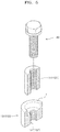
- Fig. 5 illustrates an embodiment of a temporarily fixing part (f) in FIG. 4 .
- Fig. 6 illustrates an embodiment of the coupling block 150 in FIG. 4 .
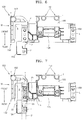
- FIG. 7 illustrates an embodiment of a bus bar structure coupled to the coupling block 150 in FIG. 4 .
- the circuit unit 20 may be placed on the frame 11, and the coupling block 150 may be placed on the circuit unit 20 to accommodate the circuit unit 20.
- the connector 110 and fuse block 120 may be arranged on the coupling block 150.
- the coupling block 150 may include an accommodation part G to accommodate the circuit unit 20 and first and second coupling parts 151 and 152 on a side opposite the accommodation part G.
- the coupling block 150 may support the connector 110 and the fuse block 120 at upward positions, which are spaced from the frame 11 by a certain amount or greater.
- the connector 110 and the fuse block 120 may be exposed from the cover 12 which covers the frame 11.
- the connector 110 and the fuse block 120 may be at upward positions from the frame 11, which are spaced from the frame 11 by a certain amount or greater.
- the coupling block 150 may include a box-shaped basic structure 155 to accommodate the circuit unit 20 in a lower portion of the basic structure 155 and uphold the connector 110 and the fuse block 120 on an upper portion of the basic structure 155.
- the lower portion of the basic structure 155 may form the accommodation part G.
- the upper portion of the basic structure 155 may include the first and second coupling parts 151 and 152.
- the basic structure 155 may have a box shape open toward the circuit unit 20.
- the box shape refers to a structure having an open bottom to accommodate the circuit unit 20. In one embodiment, the box shape may have a shape different from a closed shape covering the circuit unit 20.
- the bottom of the basic structure 155 is open to accommodate the circuit unit 20.
- the basic structure 155 may include an opening 155' in a side thereof, to expose a front side of the circuit unit 20 in the basic structure 155.
- the basic structure 155 may include the opening 155' in a side thereof.
- the front side of the circuit unit 20 may be exposed through the opening 155'.
- the circuit unit 20 may include a plurality of heat-generating devices.
- the basic structure 155 need not completely cover the circuit unit but may allow exposure of the circuit unit 20 for efficient cooling of the circuit unit 20.
- the basic structure 155 may have an open bottom to accommodate the circuit unit 20.
- the opening 155' of the basic structure 155 may be connected to the open bottom.
- the coupling block 150 may include temporarily fixing parts (f) to temporarily fix the connector 110 and the fuse block 120.
- the connector 110 and the fuse block 120 may be placed above the frame 11.
- a coupling operation for the connector 110 and the fuse block 120 may be performed through the cover 12 covering the frame 11.
- the positions of the connector 110 and the fuse block 120 may be temporarily maintained above the frame 11 until a coupling operation for fixing the connector 110 and the fuse block 120 is performed.
- the coupling block 150 includes the temporarily fixing parts (f) for the connector 110 and the fuse block 120, the positions of the connector 110 and the fuse block 120 may be maintained until the coupling operation is performed after the frame 11 is covered with the cover 12. This structure may reduce the efforts of a worker to hold and support the connector 110 and the fuse block 120 under the cover 12.
- the temporarily fixing parts (f) may be formed at various positions of the coupling block 150, as long as the temporarily fixing parts (f) temporarily fix the connector 110 and the fuse block 120, via physical interference with the connector 110 and the fuse block 120, until the connector 110 and the fuse block 120 are finally fixed using fasteners 60.
- the temporarily fixing parts (f) may be on the first and second coupling parts 151 and 152 provided to finally fix the connector 110 and the fuse block 120.
- the temporarily fixing parts (f) are on the first and second coupling parts 151 and 152 that finally fix the connector 110 and the fuse block 120, the difference between temporary and final fixing positions may be reduced even though temporary fixing positions are varied. Also, aligning may be effectively performed in a final coupling operation.
- the first and second coupling parts 151 and 152 may be on upper portions of the coupling block 150, e.g., upper portions of the basic structure 155.
- the first and second coupling parts 151 and 152 for coupling with the connector 110 and fuse block 120 may be at exclusive positions in a non-overlapping manner.
- the first and second coupling parts 151 and 152 may be formed on left and right sides at different positions.
- the connector 110 may be coupled to the first coupling part 151
- the fuse block 120 may be coupled to the second coupling part 152.
- the first coupling part 151 may be formed directly on the basic structure 155.
- the second coupling part 152 may include a wing W extending from the basic structure 155.
- the wing W may have a bent shape with a bending point B, from which the wing W extends in different directions, and may provide coupling positions corresponding to corners of the fuse block 120.
- Each of the connector 110 and the fuse block 120 has a predetermined shape, e.g., rectangular shape with four corners.
- the first and second coupling parts 151 and 152 may be formed at positions corresponding to the four corners of the connector 110 and the four corners of the fuse block 120.
- the first and second coupling parts 151 and 152 may be selectively formed at positions corresponding to some of the four corners of the connector 110 and the four corners of the fuse block 120.
- the first and second coupling parts 151 and 152 may be formed at positions corresponding to at least one of the four corners of the connector 110 and at least one of the four corners of the fuse block 120.
- a plurality of first coupling part 151 are at positions corresponding to at least two of the four corners of the connector 110.
- a plurality of second coupling parts 152 are at positions corresponding to at least two of the four corners of the fuse block 120.
- the first and second coupling parts 151 and 152 may include the temporarily fixing parts (f) to temporarily fix the connector 110 and the fuse block 120.
- the temporarily fixing parts (f) may be around coupling holes 151' and 152' of the first and second coupling parts 151 and 152.
- the temporarily fixing parts (f) may include walls surrounding the coupling holes 151' and 152'. Assembly protrusions 111 and 121 on the connector 110 and the fuse block 120 may be inserted into the temporarily fixing parts (f).
- the temporarily fixing parts (f) may be respectively formed on the first and second coupling parts 151 and 152 at plurality of positions, to temporarily fix the connector 110 and the fuse block 120.
- Some of the temporarily fixing parts (f) at different positions as described above may have a hollow cylinder shape completely surrounding the assembly protrusions 111 and 121. Other ones of the temporarily fixing parts (f) may have a shape partially surrounding the assembly protrusions 111 and 121. Referring to FIG. 4 , the temporarily fixing parts (f) may be at positions corresponding to the four corners of the fuse block 120. Some of the temporarily fixing parts (f) may completely surround some of the assembly protrusions 121. Other ones of the temporarily fixing parts (f) may partially surround the others of the assembly protrusions 121.
- This structure may be provided by taking assembly tolerance into account, in order to reduce misalignment between assembly positions of the temporarily fixing parts (f) and the fuse block 120 (that is, the assembly protrusions 121) caused by machining errors or thermal expansion.
- the temporarily fixing parts (f) partially surrounding the assembly protrusions 121 may absorb assembly tolerance.
- the assembly protrusions 111 and 121 may protrude downward from the connector 110 and the fuse block 120 toward the coupling block 150.
- Each of the connector 110 and the fuse block 120 may have a predetermined shape, e.g., rectangular shape with four corners.
- the assembly protrusions 111 and 121 may respectively be formed on the corners of the connector 110 and the fuse block 120.
- the connector 110 and the fuse block 120 may be temporarily fixed by inserting the assembly protrusions 111 and 121 into the temporarily fixing parts (f).
- the assembly protrusions 111 and 121 may include penetration holes to receive fasteners 60.
- the connector 110 and the fuse block 120 may be finally fixed by coupling the fasteners 60 inserted into the assembly protrusions 111 and 121 to the coupling holes 151' and 152'.
- the connector 110 and the fuse block 120 may be temporarily fixed to upper portions of the coupling block 150, by inserting the assembly protrusions 111 and 121 protruding downward from the connector 110 and the fuse block 120 into the temporarily fixing parts (f) of the coupling block 150.
- the penetration holes of the connector 110 and the fuse block 120 may be aligned with the coupling holes 151' and 152' of the coupling block 150.
- the fasteners 60 may be moved from an upper side of the cover 12 to the connector 110 and the fuse block 120 exposed through the opening 12' of the cover 12, and may be coupled to the coupling holes 151' and 152' of the coupling block 150 through the penetration holes of the connector 110 and the fuse block 120, in order to finally fix the connector 110 and the fuse block 120.
- the fuse block 120 may be formed along a charge/discharge path formed by first, second, and third bus bars 31, 32, and 33.
- the fuse block 120 may interrupt the charge/discharge path in abnormal situations, e.g., an overheating situation or an overcurrent situation.
- a guide 154 for guiding and supporting the first, second and third bus bars 31, 32, and 33 is on a side of the coupling block 150 to which the fuse block 120 is coupled.
- the first, second, and third bus bars 31, 32, and 33 may be supported on the guide 154 and may form a current path with the fuse block 120.
- the coupling block 150 may include support protrusions P around which the first, second, and third bus bars 31, 32, and 33 are fitted.
- the first and second bus bars 31 and 32 may be fitted around one of the support protrusion P in an overlapping manner.
- the first and second bus bars 31 and 32 may be in conductive contact with one of the support protrusions P and may form a charge/discharge path.
- the support protrusion P may include a conductive metallic material to reduce electric resistance between the support protrusions P and the first and second bus bars 31 and 32.
- the coupling block 150 including the guide 154 may include an insulative material to function as an insulator for the first and second bus bars 31 and 32.
- the support protrusion P, around which the first and second bus bars 31 and 32 are fitted may include a conductive material.
- the support protrusion P may be on the guide 154 supported by the first and second bus bars 31 and 32.
- the fuse block 120 (or the fuse box coupled to the upper portion of the fuse block 120) may include a fuse 35 forming a charge/discharge path.
- the second and third bus bars 32 and 33 may be connected to different ends of the fuse 35, so that the second and third bus bars 32 and 33 may be electrically connected to each other through the fuse 35.
- the second bus bar 32 and an end of the fuse 35 may be fitted around one of the support protrusions P, to make conductive contact with each other in an overlapping manner.
- the third bus bar 33 and the other end of the fuse 35 may be fitted around another one of the support protrusions P, to make conductive contact with each other in an overlapping manner.
- the second and third bus bars 32 and 33 may form a bypass including the fuse block 120.
- the bypass discharge/discharge path
- the bypass may or may not conduct electricity according to the state of the fuse 35. Before and after a turning point, current may flow into and out from the fuse block 120 through the second and third bus bars 32 and 33.
- a leg L may be on a lower portion of the coupling block 150 (e.g., a lower portion of the basic structure 155).
- the coupling block 150 may be placed on the frame 11 through the leg L.
- the leg L may have, for example, a flange shape extending from the bottom of the basic structure 155 toward the frame 11.
- the leg L may include a third coupling part 153 for coupling with the frame 11.
- the coupling block 150 may be fixed to the frame 11 via fasteners inserted through the third coupling part 153.
- the coupling block 150 may be formed in one-piece. In one embodiment, the coupling block 150 may be entirely formed of an insulative material. The coupling block 150 may include an insulative material to prevent electric interference with the circuit unit the connector 110, and the fuse block 120.
- a safety device 125 may be on the coupling block 150.
- the safety device 125 may be in a safety device pocket which surrounds the safety device 125. If an abnormal situation (e.g., overheating or overcurrent) occurs, the safety device 125 may limit a charge/discharge current flowing through the connector 110 to prevent accidents such as explosions or fires.
- the connector 110 may include terminals having different polarities.
- the safety device 125 may be placed along a charge/discharge path including the connector 110, by connecting the safety device 125 to one of the terminals of the connector 110.
- the safety device 125 may include a variable resistor having temperature-dependent resistance or a fuse to interrupt current according to Joule heating.
- a support structure for supporting the connector 110 and the fuse block 120 at intended heights e.g. relative to the frame, e.g. from base portion thereof.
- the connector 110 and the fuse block 120 may be externally exposed, and the connector 110 and the fuse block 120 may be easily connected when supplying power.
- a battery module may be easily assembled.
- a temporarily fixing structure may temporarily fix a connector and fuse block exposed to the outside at their intended heights (e.g. relative to the frame, e.g. from base portion thereof).
- the connector 110 and the fuse block 120 may be temporarily fixed before being finally fixed.
- a final fixing operation may be easily performed.
- embodiments of the invention can provide a battery module, comprising: a battery pack; a circuit arranged to control charge and discharge operations of the battery pack; a connector through which current is output from the battery pack (e.g. to an external device); a fuse block arranged to selectively interrupt current of the battery pack; a frame arranged to support the circuit, the connector, and the fuse block; and a coupling block arranged within the frame, the coupling block accommodating the circuit at a first position relative to the frame and supporting the connector and the fuse block at second positions relative to the frame (e.g. with the connector and the fuse block supported at different second positions). The second positions may be further from the frame than the first position.
- the coupling block may include: a basic structure; an accommodation part at a first portion of the basic structure to accommodate the circuit; and first and second coupling parts at second portions of the basic structure to be coupled with the connector and the fuse block.
- the first portion of the basic structure may be nearer the frame than the second portions of the basic structure.
- the first and second coupling parts may include temporary fixing parts arranged to fix the connector and the fuse block.
- the temporary fixing parts may fix the connector and the fuse block in place relative to the frame - e.g. at their intended heights (e.g. from the frame).
- the frame may comprises a base portion and a number of side portions, and wherein the coupling block is arranged to accommodate the circuit at the first position that is relatively proximate to the base portion, and is arranged to support the connector and the fuse block at the second positions that are relatively further away from the base portion.
- the frame may have a structure that has a base portion and a number of side portions (e.g. four side portions or side walls), the side portions defining an opening in the frame.
- the coupling block may accommodate the circuit at a position that is relatively proximate to the base portion, and may support the connector and the fuse block at positions relatively further away from the base portion. Hence, the coupling block may support the connector and fuse block at their intended distances away from the base portion of the frame.
- the battery module may further comprise a cover arranged to cover the opening of the frame (e.g. the cover may face the base portion of the frame). The connector and the fuse block may be exposed through the cover (e.g. through one or more openings in the cover).
- Embodiments of the invention can provide a method of assembling a battery module that comprises a battery pack; a circuit arranged to control charge and discharge operations of the battery pack; a connector through which current is output from the battery pack; a fuse block arranged to selectively interrupt current of the battery pack; a frame arranged to support the circuit, the connector, and the fuse block; and a coupling block, the method comprising: using the coupling block to accommodate the circuit at a first position relative to the frame and using the coupling block to support the connector and the fuse block at positions further from the frame than the first position.
- the connector and the fuse block may include assembly protrusions, and during assembly the assembly protrusions may inserted into temporary fixing parts in the coupling block.
- a temporarily fixing structure may temporarily fix a connector and fuse block exposed to the outside at their intended heights (e.g. from the frame).
- Example embodiments have been disclosed herein, and although specific terms are employed, they are used and are to be interpreted in a generic and descriptive sense only and not for purpose of limitation. In some instances, as would be apparent to one of ordinary skill in the art as of the filing of the present application, features, characteristics, and/or elements described in connection with a particular embodiment may be used singly or in combination with features, characteristics, and/or elements described in connection with other embodiments unless otherwise indicated. Accordingly, various changes in form and details may be made without departing from the scope of the embodiments set forth in the claims.
Landscapes
- Chemical & Material Sciences (AREA)
- Chemical Kinetics & Catalysis (AREA)
- Electrochemistry (AREA)
- General Chemical & Material Sciences (AREA)
- Engineering & Computer Science (AREA)
- Manufacturing & Machinery (AREA)
- Microelectronics & Electronic Packaging (AREA)
- Battery Mounting, Suspending (AREA)
- Connection Of Batteries Or Terminals (AREA)
Abstract
Description
- One or more example embodiments described herein relate to a battery module.
- Secondary (rechargeable) batteries power mobile devices, electric vehicles, hybrid electric vehicles, electric bicycles, uninterruptible power supplies, and other electronics. Multi-cell batteries (battery modules) are used for higher power applications, while single-cell batteries are used for lower power applications. For example, single-cell secondary batteries power cellular phones and other small mobile devices. Battery modules with high-output, high-capacity features power devices which are to operate for long periods of time and which consume large amounts of power, e.g., electric vehicles and hybrid electric vehicles. The output voltages or currents of battery modules may be adjusted by adjusting the number of battery cells in the battery modules.
- In accordance with one or more embodiments, a battery module includes a battery pack; a circuit to control charge and discharge operations of the battery pack; a connector through which current is output from the battery pack; a fuse block to selectively interrupt current of the battery pack; a frame to support the circuit, the connector, and the fuse block; and a coupling block accommodating the circuit at a first side and supporting the connector and the fuse block at a second side at upward positions relative to the frame.
- The coupling block may include a basic structure; an accommodation part at a lower portion of the basic structure to accommodate the circuit; and first and second coupling parts at upper portions of the basic structure to be coupled with the connector and the fuse block. The first and second coupling parts may include temporarily fixing parts to fix the connector and the fuse block. The first and second coupling parts may include coupling holes, and the battery module may include fasteners inserted through the connector and the fuse block and fitted to the coupling holes.
- The connector and the fuse block may include assembly protrusions inserted into the temporarily fixing parts. The temporarily fixing parts may include walls entirely or partially surrounding the assembly protrusions. The first and second coupling parts may be at exclusive positions in a non-overlapping manner. A plurality of first coupling parts may be at positions corresponding to at least two of four corners of the connector, and a plurality of second coupling parts may be at positions corresponding to at least two of four corners of the fuse block.
- The first coupling part may be on an upper portion of the basic structure, and the second coupling part may include a wing extending from the basic structure. The wing may include a bending point from which the wing extends in different directions. The basic structure may have a box shape with an open lower side to accommodate the circuit, and a leg with a flange shape for the frame, the leg may be on the opened lower side of the basic structure. The leg may include a third coupling part coupled to the frame. The basic structure may include an opening exposing a front side of the circuit.
- The battery module may include a bus bar to provide a current flow path with the fuse block, wherein the coupling block includes a support protrusion and wherein the bus bar is fitted around the support protrusion. The coupling block may include a guide to guide the bus bar. First and second bus bars may be fitted around the support protrusion in an overlapping manner and are electrically connected to the support protrusion. The support protrusion may include a metallic material.
- The bus bar may include first and second bus bars electrically connected to each other through a fuse of the fuse block, and the fuse and at least one of the first or second bus bars may be fitted around the support protrusion in an overlapping manner. The battery module may include a cover covering an upper portion of the frame, wherein the connector and the fuse block are exposed from an upper portion of the cover. The connector and the fuse block may be coupled to the coupling block, and the connector and the fuse box may be coupled to the coupling block from an upper side of the cover when the connector and the fuse block are temporarily fixed to the coupling block.
- In accordance with one or more embodiments, there is provided a battery module, comprising: a battery pack; a circuit arranged to control charge and discharge operations of the battery pack; a connector through which current is output from the battery pack (e.g. to an external device); a fuse block arranged to selectively interrupt current of the battery pack; a frame arranged to support the circuit, the connector, and the fuse block; and a coupling block arranged within the frame, the coupling block accommodating the circuit at a first position relative to the frame and supporting the connector and the fuse block at positions further from the frame than the first position.
- In accordance with one or more embodiments, there is provided a method of assembling a battery module that comprises a battery pack; a circuit arranged to control charge and discharge operations of the battery pack; a connector through which current is output from the battery pack; a fuse block arranged to selectively interrupt current of the battery pack; a frame arranged to support the circuit, the connector, and the fuse block; and a coupling block, the method comprising: using the coupling block to accommodate the circuit at a first position relative to the frame and using the coupling block to support the connector and the fuse block at positions further from the frame than the first position.
- The connector and the fuse block may include assembly protrusions, and during assembly the assembly protrusions may inserted into temporary fixing parts in the coupling block. Hence, during assembly, a temporarily fixing structure may temporarily fix a connector and fuse block exposed to the outside at their intended heights (e.g. from the frame).
- According to an aspect of the invention, there is provided a battery module as set out in claim 1. Preferred features are set out in claims 2 to 15.
- Features will become apparent to those of skill in the art by describing in detail exemplary embodiments with reference to the attached drawings in which:
-
FIG. 1 illustrates an embodiment of a battery module; -
FIG. 2 illustrates an internal embodiment of the battery module; -
FIG. 3 illustrates another view of the battery module; -
FIG. 4 illustrates another view of the battery module; -
Fig. 5 illustrates an embodiment of a temporarily fixing part; -
Fig. 6 illustrates an embodiment of a coupling block; and -
Fig. 7 illustrates an embodiment of a bus bar structure. - Example embodiments will now be described with reference to the accompanying drawings; however, they may be embodied in different forms and should not be construed as limited to the embodiments set forth herein. Rather, these embodiments are provided so that this disclosure will be thorough and complete, and will fully convey exemplary implementations to those skilled in the art. The embodiments (or portions thereof) may be combined to form additional embodiments.
- In the drawings, the dimensions of layers and regions may be exaggerated for clarity of illustration. It will also be understood that when a layer or element is referred to as being "on" another layer or substrate, it can be directly on the other layer or substrate, or intervening layers may also be present. Further, it will be understood that when a layer is referred to as being "under" another layer, it can be directly under, and one or more intervening layers may also be present. In addition, it will also be understood that when a layer is referred to as being "between" two layers, it can be the only layer between the two layers, or one or more intervening layers may also be present. Like reference numerals refer to like elements throughout.
- When an element is referred to as being "connected" or "coupled" to another element, it can be directly connected or coupled to the another element or be indirectly connected or coupled to the another element with one or more intervening elements interposed therebetween. In addition, when an element is referred to as "including" a component, this indicates that the element may further include another component instead of excluding another component unless there is different disclosure.
-
FIG. 1 illustrates an embodiment of a battery module.FIG. 2 is an exploded perspective view of an internal embodiment of the battery module.FIG. 3 is a partial perspective view of the battery module. - Referring to
FIGS. 1 to 3 , the battery module may include ahousing 10 accommodating abattery pack 50. Thehousing 10 may include aframe 11 coupled to acover 12, with thebattery pack 50 therebetween. In one example embodiment, the battery module may include one ormore battery packs 50. For example, a plurality ofbattery packs 50 may be electrically connected in series, parallel, or series-parallel to provide a required degree of electric power. - A
circuit unit 20, inframe 11, may control charge and discharge operations of thebattery pack 50. Aconnector 110 may be provided above theframe 11 to carry current output from thebattery pack 50. Afuse block 120 may be provided above theframe 11 to selectively interrupt current of thebattery pack 50 when the battery pack 50 malfunctions. In addition, acoupling block 150 may be placed on theframe 11 to support theconnector 110 andfuse block 120 at upward positions with respect to theframe 11. Hence, the coupling block 159 may be arranged to accommodate thecircuit unit 20 at the first position that is relatively proximate to a base portion of theframe 11, and may be arranged to support the connector 1110 and thefuse block 120 at the second positions that are relatively further away from the base portion of theframe 11. - The
cover 12 may cover the frame 11 (e.g. it may face the base portion of the frame 11), above which theconnector 110 and thefuse block 120 are placed. Thecover 12 may include an opening 12' to expose theconnector 110 and thefuse block 120. Theconnector 110 and thefuse block 120 may be exposed through the opening 12' of thecover 12. Thus, a coupling operation may be performed from an upper side of thecover 12. For example, when theconnector 110 and thefuse block 120 are temporarily fixed to upper portions of thecoupling block 150, theframe 11 may be covered with thecover 12. Then, theconnector 110 and the fuse block 120 (which is exposed through the opening 12' of the cover 12) may be securely fixed using fasteners. - The
connector 110 is exposed from thecover 12 to supply electricity of thebattery pack 50 to an external device through theconnector 110. The battery module may supply driving power to a device (e.g., a vehicle), and theconnector 110 may form an output terminal for supplying driving power. Theconnector 110 may be used to supply driving power to one or more electric components of the vehicle, in addition to or instead of supplying driving power to the vehicle. In one embodiment, the battery module may further include a high-voltage connector 180 to supply driving power. - The
fuse block 120 may be exposed from thecover 12. A fuse box, forming a charge/discharge path of thebattery pack 50, may be coupled to an upper portion of thefuse block 120. The fuse box may be placed along the charge/discharge path and may interrupt charge/discharge current when errors (e.g., overheating or overcurrent) occur. For example, the fuse box may include a variable resistor having temperature-dependent resistance or a fuse to block the charge/discharge path according to Joule heating. The charge/discharge path may be formed, for example, by coupling the fuse box to the upper portion of thefuse block 120. Then, the battery module may be ready to operate. -
FIG. 4 is an exploded perspective view illustrating a portion of the battery module inFIG. 1 .Fig. 5 illustrates an embodiment of a temporarily fixing part (f) inFIG. 4 .Fig. 6 illustrates an embodiment of thecoupling block 150 inFIG. 4 .FIG. 7 illustrates an embodiment of a bus bar structure coupled to thecoupling block 150 inFIG. 4 . - Referring to
FIG. 4 , thecircuit unit 20 may be placed on theframe 11, and thecoupling block 150 may be placed on thecircuit unit 20 to accommodate thecircuit unit 20. Theconnector 110 and fuse block 120 may be arranged on thecoupling block 150. - The
coupling block 150 may include an accommodation part G to accommodate thecircuit unit 20 and first andsecond coupling parts coupling block 150 may support theconnector 110 and thefuse block 120 at upward positions, which are spaced from theframe 11 by a certain amount or greater. Theconnector 110 and thefuse block 120 may be exposed from thecover 12 which covers theframe 11. Theconnector 110 and thefuse block 120 may be at upward positions from theframe 11, which are spaced from theframe 11 by a certain amount or greater. - The
coupling block 150 may include a box-shapedbasic structure 155 to accommodate thecircuit unit 20 in a lower portion of thebasic structure 155 and uphold theconnector 110 and thefuse block 120 on an upper portion of thebasic structure 155. The lower portion of thebasic structure 155 may form the accommodation part G. The upper portion of thebasic structure 155 may include the first andsecond coupling parts basic structure 155 may have a box shape open toward thecircuit unit 20. The box shape refers to a structure having an open bottom to accommodate thecircuit unit 20. In one embodiment, the box shape may have a shape different from a closed shape covering thecircuit unit 20. The bottom of thebasic structure 155 is open to accommodate thecircuit unit 20. In addition, thebasic structure 155 may include an opening 155' in a side thereof, to expose a front side of thecircuit unit 20 in thebasic structure 155. - In the example embodiment, the
basic structure 155 may include the opening 155' in a side thereof. The front side of thecircuit unit 20 may be exposed through the opening 155'. Thecircuit unit 20 may include a plurality of heat-generating devices. Thus, thebasic structure 155 need not completely cover the circuit unit but may allow exposure of thecircuit unit 20 for efficient cooling of thecircuit unit 20. For example, thebasic structure 155 may have an open bottom to accommodate thecircuit unit 20. The opening 155' of thebasic structure 155 may be connected to the open bottom. - The
coupling block 150 may include temporarily fixing parts (f) to temporarily fix theconnector 110 and thefuse block 120. Theconnector 110 and thefuse block 120 may be placed above theframe 11. A coupling operation for theconnector 110 and thefuse block 120 may be performed through thecover 12 covering theframe 11. In other words, since theconnector 110 and thefuse block 120 are fixed above theframe 11 after an upper side of theframe 11 is covered with thecover 12, the positions of theconnector 110 and thefuse block 120 may be temporarily maintained above theframe 11 until a coupling operation for fixing theconnector 110 and thefuse block 120 is performed. Since thecoupling block 150 includes the temporarily fixing parts (f) for theconnector 110 and thefuse block 120, the positions of theconnector 110 and thefuse block 120 may be maintained until the coupling operation is performed after theframe 11 is covered with thecover 12. This structure may reduce the efforts of a worker to hold and support theconnector 110 and thefuse block 120 under thecover 12. - The temporarily fixing parts (f) may be formed at various positions of the
coupling block 150, as long as the temporarily fixing parts (f) temporarily fix theconnector 110 and thefuse block 120, via physical interference with theconnector 110 and thefuse block 120, until theconnector 110 and thefuse block 120 are finally fixed usingfasteners 60. In the example embodiment, the temporarily fixing parts (f) may be on the first andsecond coupling parts connector 110 and thefuse block 120. As described above, if the temporarily fixing parts (f) are on the first andsecond coupling parts connector 110 and thefuse block 120, the difference between temporary and final fixing positions may be reduced even though temporary fixing positions are varied. Also, aligning may be effectively performed in a final coupling operation. - The first and
second coupling parts coupling block 150, e.g., upper portions of thebasic structure 155. For example, the first andsecond coupling parts connector 110 and fuse block 120 may be at exclusive positions in a non-overlapping manner. For example, the first andsecond coupling parts connector 110 may be coupled to thefirst coupling part 151, and thefuse block 120 may be coupled to thesecond coupling part 152. - The
first coupling part 151 may be formed directly on thebasic structure 155. Thesecond coupling part 152 may include a wing W extending from thebasic structure 155. The wing W may have a bent shape with a bending point B, from which the wing W extends in different directions, and may provide coupling positions corresponding to corners of thefuse block 120. Each of theconnector 110 and thefuse block 120 has a predetermined shape, e.g., rectangular shape with four corners. The first andsecond coupling parts connector 110 and the four corners of thefuse block 120. The first andsecond coupling parts connector 110 and the four corners of thefuse block 120. For example, the first andsecond coupling parts connector 110 and at least one of the four corners of thefuse block 120. - In the battery module of the present example embodiment, a plurality of
first coupling part 151 are at positions corresponding to at least two of the four corners of theconnector 110. Similarly, a plurality ofsecond coupling parts 152 are at positions corresponding to at least two of the four corners of thefuse block 120. - Referring to
FIG. 5 , the first andsecond coupling parts connector 110 and thefuse block 120. The temporarily fixing parts (f) may be around coupling holes 151' and 152' of the first andsecond coupling parts Assembly protrusions connector 110 and thefuse block 120 may be inserted into the temporarily fixing parts (f). The temporarily fixing parts (f) may be respectively formed on the first andsecond coupling parts connector 110 and thefuse block 120. Some of the temporarily fixing parts (f) at different positions as described above may have a hollow cylinder shape completely surrounding theassembly protrusions assembly protrusions FIG. 4 , the temporarily fixing parts (f) may be at positions corresponding to the four corners of thefuse block 120. Some of the temporarily fixing parts (f) may completely surround some of theassembly protrusions 121. Other ones of the temporarily fixing parts (f) may partially surround the others of theassembly protrusions 121. This structure may be provided by taking assembly tolerance into account, in order to reduce misalignment between assembly positions of the temporarily fixing parts (f) and the fuse block 120 (that is, the assembly protrusions 121) caused by machining errors or thermal expansion. The temporarily fixing parts (f) partially surrounding theassembly protrusions 121 may absorb assembly tolerance. - The assembly protrusions 111 and 121 may protrude downward from the
connector 110 and thefuse block 120 toward thecoupling block 150. Each of theconnector 110 and thefuse block 120 may have a predetermined shape, e.g., rectangular shape with four corners. The assembly protrusions 111 and 121 may respectively be formed on the corners of theconnector 110 and thefuse block 120. Theconnector 110 and thefuse block 120 may be temporarily fixed by inserting theassembly protrusions assembly protrusions fasteners 60. Theconnector 110 and thefuse block 120 may be finally fixed by coupling thefasteners 60 inserted into theassembly protrusions - During a coupling operation, the
connector 110 and thefuse block 120 may be temporarily fixed to upper portions of thecoupling block 150, by inserting theassembly protrusions connector 110 and thefuse block 120 into the temporarily fixing parts (f) of thecoupling block 150. The penetration holes of theconnector 110 and thefuse block 120 may be aligned with the coupling holes 151' and 152' of thecoupling block 150. Then, after theframe 11 is covered with thecover 12, thefasteners 60 may be moved from an upper side of thecover 12 to theconnector 110 and thefuse block 120 exposed through the opening 12' of thecover 12, and may be coupled to the coupling holes 151' and 152' of thecoupling block 150 through the penetration holes of theconnector 110 and thefuse block 120, in order to finally fix theconnector 110 and thefuse block 120. - Referring to
FIG. 7 , thefuse block 120 may be formed along a charge/discharge path formed by first, second, and third bus bars 31, 32, and 33. Thefuse block 120 may interrupt the charge/discharge path in abnormal situations, e.g., an overheating situation or an overcurrent situation. Aguide 154 for guiding and supporting the first, second and third bus bars 31, 32, and 33 is on a side of thecoupling block 150 to which thefuse block 120 is coupled. The first, second, and third bus bars 31, 32, and 33 may be supported on theguide 154 and may form a current path with thefuse block 120. - The
coupling block 150 may include support protrusions P around which the first, second, and third bus bars 31, 32, and 33 are fitted. For example, the first and second bus bars 31 and 32 may be fitted around one of the support protrusion P in an overlapping manner. For example, the first and second bus bars 31 and 32 may be in conductive contact with one of the support protrusions P and may form a charge/discharge path. The support protrusion P may include a conductive metallic material to reduce electric resistance between the support protrusions P and the first and second bus bars 31 and 32. For example, thecoupling block 150 including theguide 154 may include an insulative material to function as an insulator for the first and second bus bars 31 and 32. However, the support protrusion P, around which the first and second bus bars 31 and 32 are fitted, may include a conductive material. The support protrusion P may be on theguide 154 supported by the first and second bus bars 31 and 32. - The fuse block 120 (or the fuse box coupled to the upper portion of the fuse block 120) may include a
fuse 35 forming a charge/discharge path. The second and third bus bars 32 and 33 may be connected to different ends of thefuse 35, so that the second and third bus bars 32 and 33 may be electrically connected to each other through thefuse 35. Thesecond bus bar 32 and an end of thefuse 35 may be fitted around one of the support protrusions P, to make conductive contact with each other in an overlapping manner. Thethird bus bar 33 and the other end of thefuse 35 may be fitted around another one of the support protrusions P, to make conductive contact with each other in an overlapping manner. - The second and third bus bars 32 and 33 may form a bypass including the
fuse block 120. The bypass (charge/discharge path) may or may not conduct electricity according to the state of thefuse 35. Before and after a turning point, current may flow into and out from thefuse block 120 through the second and third bus bars 32 and 33. - Referring to
FIG. 4 , a leg L may be on a lower portion of the coupling block 150 (e.g., a lower portion of the basic structure 155). Thecoupling block 150 may be placed on theframe 11 through the leg L. The leg L may have, for example, a flange shape extending from the bottom of thebasic structure 155 toward theframe 11. The leg L may include athird coupling part 153 for coupling with theframe 11. Thecoupling block 150 may be fixed to theframe 11 via fasteners inserted through thethird coupling part 153. - The
coupling block 150 may be formed in one-piece. In one embodiment, thecoupling block 150 may be entirely formed of an insulative material. Thecoupling block 150 may include an insulative material to prevent electric interference with the circuit unit theconnector 110, and thefuse block 120. - Referring to
FIG. 6 , asafety device 125 may be on thecoupling block 150. For example, thesafety device 125 may be in a safety device pocket which surrounds thesafety device 125. If an abnormal situation (e.g., overheating or overcurrent) occurs, thesafety device 125 may limit a charge/discharge current flowing through theconnector 110 to prevent accidents such as explosions or fires. Theconnector 110 may include terminals having different polarities. Thesafety device 125 may be placed along a charge/discharge path including theconnector 110, by connecting thesafety device 125 to one of the terminals of theconnector 110. Thesafety device 125 may include a variable resistor having temperature-dependent resistance or a fuse to interrupt current according to Joule heating. - According to the present example embodiment, a support structure for supporting the
connector 110 and thefuse block 120 at intended heights (e.g. relative to the frame, e.g. from base portion thereof) is provided. Thus, theconnector 110 and thefuse block 120 may be externally exposed, and theconnector 110 and thefuse block 120 may be easily connected when supplying power. - In accordance with one or more of the aforementioned embodiments, a battery module may be easily assembled. A temporarily fixing structure may temporarily fix a connector and fuse block exposed to the outside at their intended heights (e.g. relative to the frame, e.g. from base portion thereof). The
connector 110 and thefuse block 120 may be temporarily fixed before being finally fixed. Thus, a final fixing operation may be easily performed. - As discussed, embodiments of the invention can provide a battery module, comprising: a battery pack; a circuit arranged to control charge and discharge operations of the battery pack; a connector through which current is output from the battery pack (e.g. to an external device); a fuse block arranged to selectively interrupt current of the battery pack; a frame arranged to support the circuit, the connector, and the fuse block; and a coupling block arranged within the frame, the coupling block accommodating the circuit at a first position relative to the frame and supporting the connector and the fuse block at second positions relative to the frame (e.g. with the connector and the fuse block supported at different second positions). The second positions may be further from the frame than the first position.
- The coupling block may include: a basic structure; an accommodation part at a first portion of the basic structure to accommodate the circuit; and first and second coupling parts at second portions of the basic structure to be coupled with the connector and the fuse block. The first portion of the basic structure may be nearer the frame than the second portions of the basic structure.
- The first and second coupling parts may include temporary fixing parts arranged to fix the connector and the fuse block. For example, during assembly, the temporary fixing parts may fix the connector and the fuse block in place relative to the frame - e.g. at their intended heights (e.g. from the frame).
- The frame may comprises a base portion and a number of side portions, and wherein the coupling block is arranged to accommodate the circuit at the first position that is relatively proximate to the base portion, and is arranged to support the connector and the fuse block at the second positions that are relatively further away from the base portion.
- The frame may have a structure that has a base portion and a number of side portions (e.g. four side portions or side walls), the side portions defining an opening in the frame. The coupling block may accommodate the circuit at a position that is relatively proximate to the base portion, and may support the connector and the fuse block at positions relatively further away from the base portion. Hence, the coupling block may support the connector and fuse block at their intended distances away from the base portion of the frame. The battery module may further comprise a cover arranged to cover the opening of the frame (e.g. the cover may face the base portion of the frame). The connector and the fuse block may be exposed through the cover (e.g. through one or more openings in the cover).
- Embodiments of the invention can provide a method of assembling a battery module that comprises a battery pack; a circuit arranged to control charge and discharge operations of the battery pack; a connector through which current is output from the battery pack; a fuse block arranged to selectively interrupt current of the battery pack; a frame arranged to support the circuit, the connector, and the fuse block; and a coupling block, the method comprising: using the coupling block to accommodate the circuit at a first position relative to the frame and using the coupling block to support the connector and the fuse block at positions further from the frame than the first position.
- The connector and the fuse block may include assembly protrusions, and during assembly the assembly protrusions may inserted into temporary fixing parts in the coupling block. Hence, during assembly, a temporarily fixing structure may temporarily fix a connector and fuse block exposed to the outside at their intended heights (e.g. from the frame).
- Example embodiments have been disclosed herein, and although specific terms are employed, they are used and are to be interpreted in a generic and descriptive sense only and not for purpose of limitation. In some instances, as would be apparent to one of ordinary skill in the art as of the filing of the present application, features, characteristics, and/or elements described in connection with a particular embodiment may be used singly or in combination with features, characteristics, and/or elements described in connection with other embodiments unless otherwise indicated. Accordingly, various changes in form and details may be made without departing from the scope of the embodiments set forth in the claims.
Claims (15)
- A battery module, comprising:a battery pack;a circuit arranged to control charge and discharge operations of the battery pack;a connector through which current is output from the battery pack;a fuse block arranged to selectively interrupt current of the battery pack;a frame arranged to support the circuit, the connector, and the fuse block; anda coupling block accommodating the circuit at a first position relative to the frame and supporting the connector and the fuse block at second positions relative to the frame.
- The battery module as claimed in claim 1, wherein the frame comprises a base portion and a number of side portions, and wherein the coupling block is arranged to accommodate the circuit at the first position that is relatively proximate to the base portion, and is arranged to support the connector and the fuse block at the second positions that are relatively further away from the base portion.
- The battery module as claimed in claim 1 or 2, wherein the coupling block includes:a basic structure;an accommodation part at a first portion of the basic structure to accommodate the circuit; andfirst and second coupling parts at second portions of the basic structure to be coupled with the connector and the fuse block.
- The battery module as claimed in claim 2, wherein the first and second coupling parts include temporary fixing parts arranged to fix the connector and the fuse block.
optionally wherein: the first and second coupling parts include coupling holes, and the battery module includes fasteners inserted through the connector and the fuse block and fitted to the coupling holes. - The battery module as claimed in claim 4, wherein the connector and the fuse block include assembly protrusions inserted into the temporary fixing parts;
optionally wherein the temporary fixing parts include walls entirely or partially surrounding the assembly protrusions. - The battery module as claimed in any one of claims 3 to 5, wherein the first and second coupling parts are at exclusive positions in a non-overlapping manner.
- The battery module as claimed in any one of claims 3 to 6, wherein:a plurality of first coupling parts are at positions corresponding to at least two of four corners of the connector, anda plurality of second coupling parts are at positions corresponding to at least two of four corners of the fuse block.
- The battery module as claimed in any one of claims 3 to 7, wherein:the first coupling part is on an upper portion of the basic structure, andthe second coupling part includes a wing extending from the basic structure.optionally wherein the wing includes a bending point from which the wing extends in different directions.
- The battery module as claimed in any one of claims 3 to 8, wherein:the basic structure has a box shape with an open lower side to accommodate the circuit, and a leg with a flange shape for the frame, the leg on the open lower side of the basic structure;optionally wherein the leg includes a third coupling part coupled to the frame.
- The battery module as claimed in any one of claims 3 to 9, wherein the basic structure includes an opening exposing a front side of the circuit.
- The battery module as claimed in any one of claims 1 to 10, further comprising:a bus bar arranged to provide a current flow path with the fuse block,wherein the coupling block includes a support protrusion and wherein the bus bar is fitted around the support protrusion.
- The battery module as claimed in claim 13, wherein the coupling block includes a guide arranged to guide the bus bar; and/or
wherein first and second bus bars are fitted around the support protrusion in an overlapping manner and are electrically connected to the support protrusion; and/or
wherein the support protrusion includes a metallic material. - The battery module as claimed in claim 11 or 12, wherein:the bus bar includes first and second bus bars electrically connected to each other through a fuse of the fuse block, andthe fuse and at least one of the first or second bus bars are fitted around the support protrusion in an overlapping manner.
- The battery module as claimed in any one of claims 1 to 13, further comprising:a cover arranged to cover a portion of the frame,wherein the connector and the fuse block are exposed through the cover.
- The battery module as claimed in claim 14, wherein the connector and the fuse block are coupled to the coupling block;
optionally wherein the connector and the fuse box are coupled to the coupling block through the cover when the connector and the fuse block are temporarily fixed to the coupling block.
Applications Claiming Priority (1)
| Application Number | Priority Date | Filing Date | Title |
|---|---|---|---|
| KR1020160098042A KR102210887B1 (en) | 2016-08-01 | 2016-08-01 | Battery module |
Publications (2)
| Publication Number | Publication Date |
|---|---|
| EP3279972A1 true EP3279972A1 (en) | 2018-02-07 |
| EP3279972B1 EP3279972B1 (en) | 2019-06-12 |
Family
ID=59363044
Family Applications (1)
| Application Number | Title | Priority Date | Filing Date |
|---|---|---|---|
| EP17181740.6A Active EP3279972B1 (en) | 2016-08-01 | 2017-07-17 | Battery module |
Country Status (4)
| Country | Link |
|---|---|
| US (1) | US10361408B2 (en) |
| EP (1) | EP3279972B1 (en) |
| KR (1) | KR102210887B1 (en) |
| CN (1) | CN107681072B (en) |
Cited By (1)
| Publication number | Priority date | Publication date | Assignee | Title |
|---|---|---|---|---|
| EP3799227A4 (en) * | 2018-08-15 | 2021-08-25 | Contemporary Amperex Technology Co., Limited | MULTIFUNCTIONAL HIGH VOLTAGE CONNECTOR AND BATTERY PRODUCT |
Families Citing this family (8)
| Publication number | Priority date | Publication date | Assignee | Title |
|---|---|---|---|---|
| CN208955294U (en) * | 2018-11-08 | 2019-06-07 | 宁德时代新能源科技股份有限公司 | Multifunctional high pressure connector |
| US10763064B2 (en) * | 2018-12-12 | 2020-09-01 | Key Safety Systems, Inc. | Electric fuse box or junction box assembly with a high voltage electric line cutter device |
| KR102573133B1 (en) | 2019-02-26 | 2023-08-30 | 주식회사 엘지에너지솔루션 | Battery module including connector having shock absorbing structure |
| KR102743036B1 (en) | 2020-02-13 | 2024-12-16 | 한국단자공업 주식회사 | connector block |
| KR102461288B1 (en) | 2020-08-25 | 2022-11-01 | 한국단자공업 주식회사 | Fuse box integrated connector block |
| CN113036273A (en) * | 2021-03-02 | 2021-06-25 | 费籁电气(上海)有限公司 | Storage device for storage performance source |
| KR102614276B1 (en) | 2021-12-24 | 2023-12-15 | 한국단자공업 주식회사 | Fuse box integrated connector block |
| CN116111268B (en) * | 2023-04-10 | 2023-07-14 | 长春捷翼汽车科技股份有限公司 | A battery pack structure |
Citations (3)
| Publication number | Priority date | Publication date | Assignee | Title |
|---|---|---|---|---|
| US20120183813A1 (en) * | 2011-01-18 | 2012-07-19 | Samsung Sdi Co., Ltd. | Battery system and energy storage system including the same |
| US20150295283A1 (en) * | 2013-10-17 | 2015-10-15 | Lg Chem, Ltd. | Battery pack |
| EP2940759A1 (en) * | 2012-12-27 | 2015-11-04 | Tyco Electronics AMP Korea Ltd. | Protective circuit module, and battery module comprising same |
Family Cites Families (8)
| Publication number | Priority date | Publication date | Assignee | Title |
|---|---|---|---|---|
| JP5284053B2 (en) * | 2008-11-17 | 2013-09-11 | 株式会社東芝 | Secondary battery pack |
| JP5721332B2 (en) | 2010-03-05 | 2015-05-20 | 矢崎総業株式会社 | Inverter terminal block installed in the motor case |
| JP5632225B2 (en) | 2010-07-30 | 2014-11-26 | 矢崎総業株式会社 | Terminal connection structure |
| JP5657984B2 (en) | 2010-10-01 | 2015-01-21 | 矢崎総業株式会社 | Terminal connection structure |
| JP5803259B2 (en) * | 2011-05-17 | 2015-11-04 | 日産自動車株式会社 | Battery pack structure for electric vehicles |
| JP2015159641A (en) | 2014-02-21 | 2015-09-03 | トヨタ自動車株式会社 | Wire harness cover |
| CN105489828B (en) * | 2014-09-15 | 2019-11-05 | 比亚迪股份有限公司 | Power battery module and power battery pack with it |
| JP5970568B2 (en) | 2015-01-07 | 2016-08-17 | 矢崎総業株式会社 | Assembling the terminal block |
-
2016
- 2016-08-01 KR KR1020160098042A patent/KR102210887B1/en active Active
-
2017
- 2017-05-17 US US15/597,561 patent/US10361408B2/en active Active
- 2017-07-17 EP EP17181740.6A patent/EP3279972B1/en active Active
- 2017-07-21 CN CN201710599122.0A patent/CN107681072B/en active Active
Patent Citations (3)
| Publication number | Priority date | Publication date | Assignee | Title |
|---|---|---|---|---|
| US20120183813A1 (en) * | 2011-01-18 | 2012-07-19 | Samsung Sdi Co., Ltd. | Battery system and energy storage system including the same |
| EP2940759A1 (en) * | 2012-12-27 | 2015-11-04 | Tyco Electronics AMP Korea Ltd. | Protective circuit module, and battery module comprising same |
| US20150295283A1 (en) * | 2013-10-17 | 2015-10-15 | Lg Chem, Ltd. | Battery pack |
Cited By (2)
| Publication number | Priority date | Publication date | Assignee | Title |
|---|---|---|---|---|
| EP3799227A4 (en) * | 2018-08-15 | 2021-08-25 | Contemporary Amperex Technology Co., Limited | MULTIFUNCTIONAL HIGH VOLTAGE CONNECTOR AND BATTERY PRODUCT |
| US11495922B2 (en) | 2018-08-15 | 2022-11-08 | Contemporary Amperex Technology Co., Limited | Multifunctional high-voltage connector and battery product |
Also Published As
| Publication number | Publication date |
|---|---|
| CN107681072A (en) | 2018-02-09 |
| EP3279972B1 (en) | 2019-06-12 |
| CN107681072B (en) | 2020-10-30 |
| KR20180014553A (en) | 2018-02-09 |
| KR102210887B1 (en) | 2021-02-02 |
| US20180034013A1 (en) | 2018-02-01 |
| US10361408B2 (en) | 2019-07-23 |
Similar Documents
| Publication | Publication Date | Title |
|---|---|---|
| EP3279972B1 (en) | Battery module | |
| US11654782B2 (en) | Battery module | |
| EP1839349B1 (en) | Sensing board assembly for secondary battery module | |
| US11450927B2 (en) | Battery module | |
| EP3671905A1 (en) | Easier to assemble battery module including bus bar frame | |
| CN113632310B (en) | Flexible circuits with fuses and batteries | |
| KR102209825B1 (en) | Battery module | |
| EP2905824B1 (en) | Battery pack | |
| CN114930634B (en) | Battery pack with fuse box holder to protect against short circuits | |
| KR102331064B1 (en) | Battery pack | |
| KR101397025B1 (en) | Lead tab assembly and battery module with the same | |
| CN100438128C (en) | Assembly case and method for secondary battery | |
| KR20200056562A (en) | Battery module | |
| JP7260651B2 (en) | Battery pack including HV wire assembly and method of manufacturing battery pack | |
| KR101483130B1 (en) | Battery Pack | |
| KR20250170319A (en) | Battery assembly and battery pack including the same | |
| KR20170078370A (en) | Apparatus for preventing Over-charge and Battery module having the same |
Legal Events
| Date | Code | Title | Description |
|---|---|---|---|
| PUAI | Public reference made under article 153(3) epc to a published international application that has entered the european phase |
Free format text: ORIGINAL CODE: 0009012 |
|
| STAA | Information on the status of an ep patent application or granted ep patent |
Free format text: STATUS: REQUEST FOR EXAMINATION WAS MADE |
|
| 17P | Request for examination filed |
Effective date: 20170718 |
|
| AK | Designated contracting states |
Kind code of ref document: A1 Designated state(s): AL AT BE BG CH CY CZ DE DK EE ES FI FR GB GR HR HU IE IS IT LI LT LU LV MC MK MT NL NO PL PT RO RS SE SI SK SM TR |
|
| AX | Request for extension of the european patent |
Extension state: BA ME |
|
| STAA | Information on the status of an ep patent application or granted ep patent |
Free format text: STATUS: EXAMINATION IS IN PROGRESS |
|
| 17Q | First examination report despatched |
Effective date: 20180925 |
|
| GRAP | Despatch of communication of intention to grant a patent |
Free format text: ORIGINAL CODE: EPIDOSNIGR1 |
|
| STAA | Information on the status of an ep patent application or granted ep patent |
Free format text: STATUS: GRANT OF PATENT IS INTENDED |
|
| INTG | Intention to grant announced |
Effective date: 20190108 |
|
| GRAS | Grant fee paid |
Free format text: ORIGINAL CODE: EPIDOSNIGR3 |
|
| GRAA | (expected) grant |
Free format text: ORIGINAL CODE: 0009210 |
|
| STAA | Information on the status of an ep patent application or granted ep patent |
Free format text: STATUS: THE PATENT HAS BEEN GRANTED |
|
| AK | Designated contracting states |
Kind code of ref document: B1 Designated state(s): AL AT BE BG CH CY CZ DE DK EE ES FI FR GB GR HR HU IE IS IT LI LT LU LV MC MK MT NL NO PL PT RO RS SE SI SK SM TR |
|
| REG | Reference to a national code |
Ref country code: GB Ref legal event code: FG4D |
|
| REG | Reference to a national code |
Ref country code: CH Ref legal event code: EP |
|
| REG | Reference to a national code |
Ref country code: AT Ref legal event code: REF Ref document number: 1143761 Country of ref document: AT Kind code of ref document: T Effective date: 20190615 |
|
| REG | Reference to a national code |
Ref country code: DE Ref legal event code: R096 Ref document number: 602017004431 Country of ref document: DE |
|
| REG | Reference to a national code |
Ref country code: IE Ref legal event code: FG4D |
|
| REG | Reference to a national code |
Ref country code: NL Ref legal event code: MP Effective date: 20190612 |
|
| REG | Reference to a national code |
Ref country code: LT Ref legal event code: MG4D |
|
| PG25 | Lapsed in a contracting state [announced via postgrant information from national office to epo] |
Ref country code: LT Free format text: LAPSE BECAUSE OF FAILURE TO SUBMIT A TRANSLATION OF THE DESCRIPTION OR TO PAY THE FEE WITHIN THE PRESCRIBED TIME-LIMIT Effective date: 20190612 Ref country code: FI Free format text: LAPSE BECAUSE OF FAILURE TO SUBMIT A TRANSLATION OF THE DESCRIPTION OR TO PAY THE FEE WITHIN THE PRESCRIBED TIME-LIMIT Effective date: 20190612 Ref country code: SE Free format text: LAPSE BECAUSE OF FAILURE TO SUBMIT A TRANSLATION OF THE DESCRIPTION OR TO PAY THE FEE WITHIN THE PRESCRIBED TIME-LIMIT Effective date: 20190612 Ref country code: NO Free format text: LAPSE BECAUSE OF FAILURE TO SUBMIT A TRANSLATION OF THE DESCRIPTION OR TO PAY THE FEE WITHIN THE PRESCRIBED TIME-LIMIT Effective date: 20190912 Ref country code: HR Free format text: LAPSE BECAUSE OF FAILURE TO SUBMIT A TRANSLATION OF THE DESCRIPTION OR TO PAY THE FEE WITHIN THE PRESCRIBED TIME-LIMIT Effective date: 20190612 Ref country code: AL Free format text: LAPSE BECAUSE OF FAILURE TO SUBMIT A TRANSLATION OF THE DESCRIPTION OR TO PAY THE FEE WITHIN THE PRESCRIBED TIME-LIMIT Effective date: 20190612 |
|
| PG25 | Lapsed in a contracting state [announced via postgrant information from national office to epo] |
Ref country code: BG Free format text: LAPSE BECAUSE OF FAILURE TO SUBMIT A TRANSLATION OF THE DESCRIPTION OR TO PAY THE FEE WITHIN THE PRESCRIBED TIME-LIMIT Effective date: 20190912 Ref country code: GR Free format text: LAPSE BECAUSE OF FAILURE TO SUBMIT A TRANSLATION OF THE DESCRIPTION OR TO PAY THE FEE WITHIN THE PRESCRIBED TIME-LIMIT Effective date: 20190913 Ref country code: RS Free format text: LAPSE BECAUSE OF FAILURE TO SUBMIT A TRANSLATION OF THE DESCRIPTION OR TO PAY THE FEE WITHIN THE PRESCRIBED TIME-LIMIT Effective date: 20190612 Ref country code: LV Free format text: LAPSE BECAUSE OF FAILURE TO SUBMIT A TRANSLATION OF THE DESCRIPTION OR TO PAY THE FEE WITHIN THE PRESCRIBED TIME-LIMIT Effective date: 20190612 |
|
| REG | Reference to a national code |
Ref country code: AT Ref legal event code: MK05 Ref document number: 1143761 Country of ref document: AT Kind code of ref document: T Effective date: 20190612 |
|
| PG25 | Lapsed in a contracting state [announced via postgrant information from national office to epo] |
Ref country code: EE Free format text: LAPSE BECAUSE OF FAILURE TO SUBMIT A TRANSLATION OF THE DESCRIPTION OR TO PAY THE FEE WITHIN THE PRESCRIBED TIME-LIMIT Effective date: 20190612 Ref country code: SK Free format text: LAPSE BECAUSE OF FAILURE TO SUBMIT A TRANSLATION OF THE DESCRIPTION OR TO PAY THE FEE WITHIN THE PRESCRIBED TIME-LIMIT Effective date: 20190612 Ref country code: PT Free format text: LAPSE BECAUSE OF FAILURE TO SUBMIT A TRANSLATION OF THE DESCRIPTION OR TO PAY THE FEE WITHIN THE PRESCRIBED TIME-LIMIT Effective date: 20191014 Ref country code: RO Free format text: LAPSE BECAUSE OF FAILURE TO SUBMIT A TRANSLATION OF THE DESCRIPTION OR TO PAY THE FEE WITHIN THE PRESCRIBED TIME-LIMIT Effective date: 20190612 Ref country code: AT Free format text: LAPSE BECAUSE OF FAILURE TO SUBMIT A TRANSLATION OF THE DESCRIPTION OR TO PAY THE FEE WITHIN THE PRESCRIBED TIME-LIMIT Effective date: 20190612 Ref country code: CZ Free format text: LAPSE BECAUSE OF FAILURE TO SUBMIT A TRANSLATION OF THE DESCRIPTION OR TO PAY THE FEE WITHIN THE PRESCRIBED TIME-LIMIT Effective date: 20190612 Ref country code: NL Free format text: LAPSE BECAUSE OF FAILURE TO SUBMIT A TRANSLATION OF THE DESCRIPTION OR TO PAY THE FEE WITHIN THE PRESCRIBED TIME-LIMIT Effective date: 20190612 |
|
| PG25 | Lapsed in a contracting state [announced via postgrant information from national office to epo] |
Ref country code: ES Free format text: LAPSE BECAUSE OF FAILURE TO SUBMIT A TRANSLATION OF THE DESCRIPTION OR TO PAY THE FEE WITHIN THE PRESCRIBED TIME-LIMIT Effective date: 20190612 Ref country code: IT Free format text: LAPSE BECAUSE OF FAILURE TO SUBMIT A TRANSLATION OF THE DESCRIPTION OR TO PAY THE FEE WITHIN THE PRESCRIBED TIME-LIMIT Effective date: 20190612 Ref country code: IS Free format text: LAPSE BECAUSE OF FAILURE TO SUBMIT A TRANSLATION OF THE DESCRIPTION OR TO PAY THE FEE WITHIN THE PRESCRIBED TIME-LIMIT Effective date: 20191012 Ref country code: SM Free format text: LAPSE BECAUSE OF FAILURE TO SUBMIT A TRANSLATION OF THE DESCRIPTION OR TO PAY THE FEE WITHIN THE PRESCRIBED TIME-LIMIT Effective date: 20190612 |
|
| REG | Reference to a national code |
Ref country code: DE Ref legal event code: R097 Ref document number: 602017004431 Country of ref document: DE |
|
| PG25 | Lapsed in a contracting state [announced via postgrant information from national office to epo] |
Ref country code: TR Free format text: LAPSE BECAUSE OF FAILURE TO SUBMIT A TRANSLATION OF THE DESCRIPTION OR TO PAY THE FEE WITHIN THE PRESCRIBED TIME-LIMIT Effective date: 20190612 Ref country code: MC Free format text: LAPSE BECAUSE OF FAILURE TO SUBMIT A TRANSLATION OF THE DESCRIPTION OR TO PAY THE FEE WITHIN THE PRESCRIBED TIME-LIMIT Effective date: 20190612 |
|
| REG | Reference to a national code |
Ref country code: BE Ref legal event code: MM Effective date: 20190731 |
|
| PLBE | No opposition filed within time limit |
Free format text: ORIGINAL CODE: 0009261 |
|
| STAA | Information on the status of an ep patent application or granted ep patent |
Free format text: STATUS: NO OPPOSITION FILED WITHIN TIME LIMIT |
|
| PG25 | Lapsed in a contracting state [announced via postgrant information from national office to epo] |
Ref country code: PL Free format text: LAPSE BECAUSE OF FAILURE TO SUBMIT A TRANSLATION OF THE DESCRIPTION OR TO PAY THE FEE WITHIN THE PRESCRIBED TIME-LIMIT Effective date: 20190612 Ref country code: DK Free format text: LAPSE BECAUSE OF FAILURE TO SUBMIT A TRANSLATION OF THE DESCRIPTION OR TO PAY THE FEE WITHIN THE PRESCRIBED TIME-LIMIT Effective date: 20190612 |
|
| 26N | No opposition filed |
Effective date: 20200313 |
|
| PG25 | Lapsed in a contracting state [announced via postgrant information from national office to epo] |
Ref country code: BE Free format text: LAPSE BECAUSE OF NON-PAYMENT OF DUE FEES Effective date: 20190731 Ref country code: IS Free format text: LAPSE BECAUSE OF FAILURE TO SUBMIT A TRANSLATION OF THE DESCRIPTION OR TO PAY THE FEE WITHIN THE PRESCRIBED TIME-LIMIT Effective date: 20200224 Ref country code: LU Free format text: LAPSE BECAUSE OF NON-PAYMENT OF DUE FEES Effective date: 20190717 Ref country code: SI Free format text: LAPSE BECAUSE OF FAILURE TO SUBMIT A TRANSLATION OF THE DESCRIPTION OR TO PAY THE FEE WITHIN THE PRESCRIBED TIME-LIMIT Effective date: 20190612 |
|
| PG2D | Information on lapse in contracting state deleted |
Ref country code: IS |
|
| PG25 | Lapsed in a contracting state [announced via postgrant information from national office to epo] |
Ref country code: IE Free format text: LAPSE BECAUSE OF NON-PAYMENT OF DUE FEES Effective date: 20190717 |
|
| REG | Reference to a national code |
Ref country code: DE Ref legal event code: R079 Ref document number: 602017004431 Country of ref document: DE Free format text: PREVIOUS MAIN CLASS: H01M0002100000 Ipc: H01M0050200000 |
|
| REG | Reference to a national code |
Ref country code: CH Ref legal event code: PL |
|
| PG25 | Lapsed in a contracting state [announced via postgrant information from national office to epo] |
Ref country code: LI Free format text: LAPSE BECAUSE OF NON-PAYMENT OF DUE FEES Effective date: 20200731 Ref country code: CH Free format text: LAPSE BECAUSE OF NON-PAYMENT OF DUE FEES Effective date: 20200731 |
|
| PG25 | Lapsed in a contracting state [announced via postgrant information from national office to epo] |
Ref country code: CY Free format text: LAPSE BECAUSE OF FAILURE TO SUBMIT A TRANSLATION OF THE DESCRIPTION OR TO PAY THE FEE WITHIN THE PRESCRIBED TIME-LIMIT Effective date: 20190612 |
|
| PG25 | Lapsed in a contracting state [announced via postgrant information from national office to epo] |
Ref country code: HU Free format text: LAPSE BECAUSE OF FAILURE TO SUBMIT A TRANSLATION OF THE DESCRIPTION OR TO PAY THE FEE WITHIN THE PRESCRIBED TIME-LIMIT; INVALID AB INITIO Effective date: 20170717 Ref country code: MT Free format text: LAPSE BECAUSE OF FAILURE TO SUBMIT A TRANSLATION OF THE DESCRIPTION OR TO PAY THE FEE WITHIN THE PRESCRIBED TIME-LIMIT Effective date: 20190612 |
|
| PG25 | Lapsed in a contracting state [announced via postgrant information from national office to epo] |
Ref country code: MK Free format text: LAPSE BECAUSE OF FAILURE TO SUBMIT A TRANSLATION OF THE DESCRIPTION OR TO PAY THE FEE WITHIN THE PRESCRIBED TIME-LIMIT Effective date: 20190612 |
|
| P01 | Opt-out of the competence of the unified patent court (upc) registered |
Effective date: 20230528 |
|
| PGFP | Annual fee paid to national office [announced via postgrant information from national office to epo] |
Ref country code: GB Payment date: 20250626 Year of fee payment: 9 |
|
| PGFP | Annual fee paid to national office [announced via postgrant information from national office to epo] |
Ref country code: FR Payment date: 20250623 Year of fee payment: 9 |
|
| PGFP | Annual fee paid to national office [announced via postgrant information from national office to epo] |
Ref country code: DE Payment date: 20250624 Year of fee payment: 9 |