EP3279830A1 - A vision system and method for a motor vehicle - Google Patents
A vision system and method for a motor vehicle Download PDFInfo
- Publication number
- EP3279830A1 EP3279830A1 EP16182309.1A EP16182309A EP3279830A1 EP 3279830 A1 EP3279830 A1 EP 3279830A1 EP 16182309 A EP16182309 A EP 16182309A EP 3279830 A1 EP3279830 A1 EP 3279830A1
- Authority
- EP
- European Patent Office
- Prior art keywords
- vision system
- code
- gatekeeper
- depth
- object detection
- Prior art date
- Legal status (The legal status is an assumption and is not a legal conclusion. Google has not performed a legal analysis and makes no representation as to the accuracy of the status listed.)
- Granted
Links
Images

Classifications
-
- G—PHYSICS
- G06—COMPUTING OR CALCULATING; COUNTING
- G06V—IMAGE OR VIDEO RECOGNITION OR UNDERSTANDING
- G06V20/00—Scenes; Scene-specific elements
- G06V20/50—Context or environment of the image
- G06V20/56—Context or environment of the image exterior to a vehicle by using sensors mounted on the vehicle
- G06V20/58—Recognition of moving objects or obstacles, e.g. vehicles or pedestrians; Recognition of traffic objects, e.g. traffic signs, traffic lights or roads
-
- G—PHYSICS
- G06—COMPUTING OR CALCULATING; COUNTING
- G06F—ELECTRIC DIGITAL DATA PROCESSING
- G06F18/00—Pattern recognition
- G06F18/20—Analysing
- G06F18/22—Matching criteria, e.g. proximity measures
-
- G—PHYSICS
- G06—COMPUTING OR CALCULATING; COUNTING
- G06T—IMAGE DATA PROCESSING OR GENERATION, IN GENERAL
- G06T7/00—Image analysis
- G06T7/50—Depth or shape recovery
- G06T7/55—Depth or shape recovery from multiple images
- G06T7/593—Depth or shape recovery from multiple images from stereo images
-
- G—PHYSICS
- G06—COMPUTING OR CALCULATING; COUNTING
- G06T—IMAGE DATA PROCESSING OR GENERATION, IN GENERAL
- G06T7/00—Image analysis
- G06T7/80—Analysis of captured images to determine intrinsic or extrinsic camera parameters, i.e. camera calibration
-
- B—PERFORMING OPERATIONS; TRANSPORTING
- B60—VEHICLES IN GENERAL
- B60Q—ARRANGEMENT OF SIGNALLING OR LIGHTING DEVICES, THE MOUNTING OR SUPPORTING THEREOF OR CIRCUITS THEREFOR, FOR VEHICLES IN GENERAL
- B60Q9/00—Arrangement or adaptation of signal devices not provided for in one of main groups B60Q1/00 - B60Q7/00, e.g. haptic signalling
- B60Q9/008—Arrangement or adaptation of signal devices not provided for in one of main groups B60Q1/00 - B60Q7/00, e.g. haptic signalling for anti-collision purposes
-
- G—PHYSICS
- G06—COMPUTING OR CALCULATING; COUNTING
- G06T—IMAGE DATA PROCESSING OR GENERATION, IN GENERAL
- G06T2207/00—Indexing scheme for image analysis or image enhancement
- G06T2207/10—Image acquisition modality
- G06T2207/10004—Still image; Photographic image
- G06T2207/10012—Stereo images
-
- G—PHYSICS
- G06—COMPUTING OR CALCULATING; COUNTING
- G06T—IMAGE DATA PROCESSING OR GENERATION, IN GENERAL
- G06T2207/00—Indexing scheme for image analysis or image enhancement
- G06T2207/10—Image acquisition modality
- G06T2207/10028—Range image; Depth image; 3D point clouds
-
- G—PHYSICS
- G06—COMPUTING OR CALCULATING; COUNTING
- G06T—IMAGE DATA PROCESSING OR GENERATION, IN GENERAL
- G06T2207/00—Indexing scheme for image analysis or image enhancement
- G06T2207/20—Special algorithmic details
- G06T2207/20021—Dividing image into blocks, subimages or windows
-
- G—PHYSICS
- G06—COMPUTING OR CALCULATING; COUNTING
- G06T—IMAGE DATA PROCESSING OR GENERATION, IN GENERAL
- G06T2207/00—Indexing scheme for image analysis or image enhancement
- G06T2207/30—Subject of image; Context of image processing
- G06T2207/30248—Vehicle exterior or interior
- G06T2207/30252—Vehicle exterior; Vicinity of vehicle
-
- G—PHYSICS
- G06—COMPUTING OR CALCULATING; COUNTING
- G06V—IMAGE OR VIDEO RECOGNITION OR UNDERSTANDING
- G06V2201/00—Indexing scheme relating to image or video recognition or understanding
- G06V2201/07—Target detection
Definitions
- the invention relates to a vision system for a motor vehicle, comprising an imaging apparatus adapted to capture images from a surrounding of the motor vehicle, and a processing device adapted to execute an object detection code to detect objects in the surrounding of the motor vehicle by processing images captured by said imaging apparatus.
- the invention relates also to a corresponding vision method.
- Such vision systems are generally known, see for example EP 2 219 133 A1 .
- objects such as other vehicles and pedestrians can be detected in many different ways, including for example classification in mono images, disparity image or optical flow object segmentation, feature point tracking, etc.
- advanced concepts typically result in a large amount of software code.
- the object detection In order to be able to use the detected objects in safety critical high level applications such as automatic emergency braking or steering assistance, the object detection must be raised to a higher functional safety level, such as Automotive Safety Integrity Level B (ASIL-B).
- ASIL-B Automotive Safety Integrity Level B
- having to write the complete object detection code in a higher functional safety level requires a lot of manpower and therefore is very expensive.
- the object of the invention is to provide a cost-effective vision system and method where objects detected by the object detection code can be used in safety critical high level applications such as automatic emergency braking or steering assistance.
- the invention solves this object with the features of the independent claims.
- the idea of the invention is to avoid having to write the complete object detection code with higher functional safety level quality. Instead a small gatekeeper code module, having a significantly smaller size than the object detection code, and having a higher safety level quality, is placed after, i.e. downstream, the object detection code which can have a non-critical safety level, like Quality Management (QM) level.
- QM Quality Management
- the amount of code that must have a higher functional safety level quality is significantly, for example at least an order of magnitude smaller, than if the complete object detection code would have to have a higher functional safety level. This contributes to an enormous reduction in manpower and costs.
- the gatekeeper module takes as input each detected object. Regardless of the object type, like other vehicle, pedestrian, general object, the gatekeeper module evaluates whether the depth image, or alternatively the disparity image, in at least a part of an area covering the detected object, matches within given tolerances the longitudinal distance of the detected object given by the object detection code. In other words, it performs an evaluation whether the depth or disparity image, at or around an image location corresponding to the world position of the detected object, contains any structure at a distance similar to that of the detected object as given by the object detection code. If this is the case, the object is considered as safe to use in a safety critical high level application.
- the gatekeeper code module may use a verified depth or disparity image which has been verified to have a higher functional safety level than a depth or disparity image obtained by said object detection code. Also the intrinsic yaw angle calibration of the imaging apparatus is preferably verified to have at least the same functional safety level as said gatekeeper code module and/or said verified depth or disparity image. The above advantageous measures contribute to raising the functional safety level of detected objects having passed the gatekeeper module.
- the gatekeeper code module is executed on a dedicated processing device, i.e. a separate electronic processing device different from the electronic processing device running the object detection code. In this manner, a hardware electric error in the processing device of the object detection code does not impair the function of the gatekeeper code module.
- the vision system 10 is mounted in a motor vehicle and comprises an imaging apparatus 11 for capturing images of a region surrounding the motor vehicle, for example a region in front of the motor vehicle.
- the imaging apparatus 11 comprises one or more optical imaging devices 12, in particular cameras, preferably operating in the visible and/or infrared wavelength range, where infrared covers near IR with wavelengths below 5 microns and/or far IR with wavelengths beyond 5 microns.
- the imaging apparatus 11 comprises a plurality of imaging devices 12 in particular forming a stereo imaging apparatus 11. In other embodiments only one imaging device 12 forming a mono imaging apparatus 11 can be used.
- the imaging apparatus 11 is coupled to a data processing device 14 adapted to process the image data received from the imaging apparatus 11.
- the data processing device 14 may comprise a pre-processing section 13 adapted to control the capture of images by the imaging apparatus 11, receive the electrical signal containing the image information from the imaging apparatus 11, rectify or warp pairs of left/right images into alignment and/or create disparity or depth images, which per se is known in the art.
- the image pre-processing section 13 may be realized by a dedicated hardware circuit, for example a Field Programmable Gate Array (FPGA) or an Application Specific Integrated Circuit (ASIC).
- FPGA Field Programmable Gate Array
- ASIC Application Specific Integrated Circuit
- the pre-processing section 13 can be realized by software in a microprocessor or a System-On-Chip (SoC) device comprising, for example, FPGA, DSP, ARM and/or microprocessor functionality.
- SoC System-On-Chip
- the pre-processing section 13 may not be needed.
- Further image and data processing carried out in the processing device 14 by an object detection code 15 comprises identifying and preferably also classifying possible objects in front of the motor vehicle, such as pedestrians, other vehicles, bicyclists and/or large animals, tracking over time the position of object candidates identified in the captured images, and activating or controlling at least one driver assistance device 18 depending on an estimation performed with respect to a tracked object, for example an estimated collision probability.
- the object detection code 15 determines, and assigns to each detected object, the world coordinates of the detected object.
- the world coordinates are the object's position relative to the vehicle, for example in meters, in particular comprising the longitudinal distance, the lateral distance and/or the height above ground of the detected object.
- the world coordinates are calculated by the object detection code 15 by using the image position of the detected object and the estimated angle of the camera (projection from the image to the outside world). Factors which may influence the world coordinates calculation are height assumptions, scale changes, flat ground assumptions, filtering over time etc. In the case of a stereo imaging apparatus 11, the depth image can be used to get more accurate coordinates especially for roads with dips and sinks, i.e. uneven roads.
- the driver assistance device 18 may in particular comprise a display device to display information relating to a detected object. However, the invention is not limited to a display device.
- the driver assistance device 18 may in addition or alternatively comprise a warning device adapted to provide a collision warning to the driver by suitable optical, acoustical and/or haptic warning signals; one or more restraint systems such as occupant airbags or safety belt tensioners, pedestrian airbags, hood lifters and the like; and/or dynamic vehicle control systems such as brake or steering control devices.
- the data processing device 14 is preferably a digital device which is programmed or programmable and preferably comprises a microprocessor, micro-controller, digital signal processor (DSP) or a System-On-Chip (SoC) device, and preferably has access to, or comprises, a memory device 25.
- the data processing devices 14, 19, pre-processing section 13 and the memory device 25 are preferably realised in an on-board electronic control unit (ECU) and may be connected to the imaging apparatus 11 via a separate cable or a vehicle data bus.
- the ECU and one or more of the imaging devices 12 can be integrated into a single unit, where a one box solution including the ECU and all imaging devices 12 can be preferred. All steps from imaging, image pre-processing, image processing to possible activation or control of driver assistance device 18 are performed automatically and continuously during driving in real time.
- the invention is explained in the following on the basis of Figures 2 and 3 .
- the left and right images 30 from the imaging apparatus 11, which here is a stereo imaging apparatus, are used to calculate a disparity image 31 by a disparity image calculation code 37 having QM quality corresponding to a non-critical functional safety level.
- the disparity image calculation code 37 may be executed for example in the pre-processing section 13, as described above, or in the processing device 14.
- the QM disparity image 31 is used by the QM object detection code 15 to detect objects 32 in the surrounding of the motor vehicle, as described above.
- the object detection code 15 is executed by the processing device 14. Without the invention, the detected objects 32 would be used for evaluating and deciding the activation of the driver assistance device 18.
- a gatekeeper code module 33 is provided in a processing device 19.
- the gatekeeper code module 33 has a higher functional safety level, for example ASIL-B level, than the object detection code 15.
- the gatekeeper module 33 lets pass only those detected objects 32 which fulfil a higher functional safety level as provided by the object detection code 15. In other words, the gatekeeper module 33 does not generate new detected objects by itself, but only checks objects detected by the object detection code 15, rejecting those which do not fulfil the higher functional safety standards of the gatekeeper module 33. This implies that the number of verified detected objects 34 verified by the gatekeeper code module 33 is equal or less the number of unverified detected objects 15.
- the gatekeeper code module 33 can be composed of a subset of the object detection code 15, re-written in higher functional safety level quality, only. That is, exactly the same object detection as performed by the object detection code 15 can be re-used in the gatekeeper code module 33, but only a few components of it are needed. This is because the goal of the functional safety module 33 is to find bugs in the QM code, and electronic errors in the processing hardware, only, both of which are easy to detect as they manifest in very large errors for the detected objects. In the above manner, the effort for producing the gatekeeper code module 33 can be strongly reduced.
- the gatekeeper code module 33 can be significantly smaller than the object detection code 15, for example less than half, like one third of the object detection code 15.
- the gatekeeper module 33 advantageously evaluates the detected objects 32 using a verified disparity image 35.
- the verification 36 of the disparity image 31 yielding the verified disparity image 35 uses a verification code having a higher functional safety level, for example ASIL-B, than the unverified disparity calculation code 37.
- the verification 36 may be done in different manners.
- the disparity data is re-calculated for a number of rows in the image, for example for every other row, or every n-th row, or any other true subset of rows. If the recalculated disparity data matches the corresponding original disparity data 31 within certain tolerances, the entire original disparity image 31 may be considered safe under the higher functional safety level (like ASIL-B), and output as the verified disparity image 35 together with a safety flag indicating "safe". If the recalculated disparity data does not match the corresponding original disparity data 31 within certain tolerances, the safety flag would be set to indicate "not safe". Therefore, the safety flag is preferably a binary flag.
- the original disparity image 31 may also be possible to amend the original disparity image 31 using the re-calculated disparity data, and to output the amended disparity image, together with the flag indicating "safe", as the verified image 35.
- Other subsets than rows of the original disparity image 31 may be re-calculated for performing the verification 36.
- the whole original disparity image 31 may be re-calculated in the verification 36. In this case, expediently the whole re-calculated disparity image is output as the verified disparity image 35.
- the gatekeeper code module 33 is executed on a dedicated hardware device 19, i.e. a separate electronic processing device 19 different from the processing device 14 executing the object detection code 15.
- the dedicated functional safety processing device 19 may be of a type mentioned above with respect to the processing device 14.
- a smaller and lower-cost dedicated functional safety processing device 19 as compared to the processing device 14, i.e. one with less processing capacities, may be well sufficient for executing the gatekeeper code module 33.
- the verification code 36 may preferably be executed on the same processing device 19 as the gatekeeper code module 33 for similar reasons.
- the operation of the gatekeeper module 33 in a preferred embodiment is illustrated on the basis of Figure 3 , showing an image captured by the imaging apparatus 11, where a truck 40 is present on the road in front of the ego vehicle. It may be assumed that the truck 40 has been detected by the QM object detection code 15, yielding an object bounding box 41.
- the gatekeeper module 33 considers the verified depth image 35 (not shown) in the region of the object bounding box 41 provided by the QM object detection code 15. In other words, the world coordinates of the detected object 32 are projected on the verified disparity image 35, resulting in a corresponding bounding box 41.
- the gatekeeper module 33 defines a grid 42 in said bounding box 41, or covering said bounding box 41, or covering said object 40 within said bounding box 41.
- the columns 43 form sub-areas in the language of the claims.
- Each box 44 is assigned dimensions, in particular a width and a height, corresponding to the maximum allowed position error for the detected object to be considered safe.
- the gatekeeper module 33 starts the verification at one end, for example the lower end, of one column 43, for example the leftmost column 43. That is, the lowest box 44 in the leftmost column is compared against the longitudinal distance world coordinate at the part of the detected object corresponding to the box 44. If the longitudinal distance of the detected object in the box 44, as calculated by the object detection code 15, matches the depth of the box 44 in the verified depth image 35 within predefined tolerances, the whole corresponding column 43 (here the leftmost column 43) is regarded safe. If not, the gatekeeper goes up one box in the same column 43, here the leftmost column 43, and performs the same comparison again for that box, and so on.
- the gatekeeper module 33 goes to the next column 43, here the second-to-left column 43, and repeats the same process, starting with the lowest box 44 of the second-to-left column 43.
- the detected object 40 is considered safe at the higher functional safety level, like ASIL-B.
- the gatekeeper 33 lets the safe object 34 pass such that safety-critical decisions like active braking or steering assistance may be based on it.
- the detected object 40 may still be considered safe at the higher functional safety level, like ASIL-B.
- the detected object 40 is considered unsafe at the higher functional safety level, like ASIL-B.
- the gatekeeper 33 rejects or discards the unsafe object 32, i.e. it cannot pass, such that safety-critical decisions like active braking or steering assistance cannot be based on it.
- a matching condition is considered fulfilled if a sufficient number of disparity pixels in the box 44 under consideration of the verified depth image 35 have a sufficiently similar longitudinal distance as the detected object 32 has at the part of the detected object corresponding to the box 44.
Landscapes
- Engineering & Computer Science (AREA)
- Theoretical Computer Science (AREA)
- Physics & Mathematics (AREA)
- General Physics & Mathematics (AREA)
- Computer Vision & Pattern Recognition (AREA)
- Data Mining & Analysis (AREA)
- Multimedia (AREA)
- Bioinformatics & Cheminformatics (AREA)
- Evolutionary Computation (AREA)
- Evolutionary Biology (AREA)
- General Engineering & Computer Science (AREA)
- Bioinformatics & Computational Biology (AREA)
- Artificial Intelligence (AREA)
- Life Sciences & Earth Sciences (AREA)
- Image Analysis (AREA)
- Traffic Control Systems (AREA)
- Image Processing (AREA)
Abstract
Description
- The invention relates to a vision system for a motor vehicle, comprising an imaging apparatus adapted to capture images from a surrounding of the motor vehicle, and a processing device adapted to execute an object detection code to detect objects in the surrounding of the motor vehicle by processing images captured by said imaging apparatus. The invention relates also to a corresponding vision method.
- Such vision systems are generally known, see for example
EP 2 219 133 A1 . - In a stereo vision camera system, objects such as other vehicles and pedestrians can be detected in many different ways, including for example classification in mono images, disparity image or optical flow object segmentation, feature point tracking, etc. Such advanced concepts typically result in a large amount of software code. In order to be able to use the detected objects in safety critical high level applications such as automatic emergency braking or steering assistance, the object detection must be raised to a higher functional safety level, such as Automotive Safety Integrity Level B (ASIL-B). However, having to write the complete object detection code in a higher functional safety level requires a lot of manpower and therefore is very expensive.
- The object of the invention is to provide a cost-effective vision system and method where objects detected by the object detection code can be used in safety critical high level applications such as automatic emergency braking or steering assistance.
- The invention solves this object with the features of the independent claims. The idea of the invention is to avoid having to write the complete object detection code with higher functional safety level quality. Instead a small gatekeeper code module, having a significantly smaller size than the object detection code, and having a higher safety level quality, is placed after, i.e. downstream, the object detection code which can have a non-critical safety level, like Quality Management (QM) level. In this manner, the amount of code that must have a higher functional safety level quality is significantly, for example at least an order of magnitude smaller, than if the complete object detection code would have to have a higher functional safety level. This contributes to an enormous reduction in manpower and costs.
- The gatekeeper module takes as input each detected object. Regardless of the object type, like other vehicle, pedestrian, general object, the gatekeeper module evaluates whether the depth image, or alternatively the disparity image, in at least a part of an area covering the detected object, matches within given tolerances the longitudinal distance of the detected object given by the object detection code. In other words, it performs an evaluation whether the depth or disparity image, at or around an image location corresponding to the world position of the detected object, contains any structure at a distance similar to that of the detected object as given by the object detection code. If this is the case, the object is considered as safe to use in a safety critical high level application.
- The gatekeeper code module may use a verified depth or disparity image which has been verified to have a higher functional safety level than a depth or disparity image obtained by said object detection code. Also the intrinsic yaw angle calibration of the imaging apparatus is preferably verified to have at least the same functional safety level as said gatekeeper code module and/or said verified depth or disparity image. The above advantageous measures contribute to raising the functional safety level of detected objects having passed the gatekeeper module.
- Preferably the gatekeeper code module is executed on a dedicated processing device, i.e. a separate electronic processing device different from the electronic processing device running the object detection code. In this manner, a hardware electric error in the processing device of the object detection code does not impair the function of the gatekeeper code module.
- In the following the invention shall be illustrated on the basis of preferred embodiments with reference to the accompanying drawings, wherein:
- Fig. 1
- shows a schematic drawing of a vision system according to the invention;
- Fig. 2
- shows a schematic flow diagram for illustrating operations within the vision system; and
- Fig. 3
- shows a captured image for illustrating operation of the gatekeeper code module.
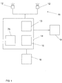
- The vision system 10 is mounted in a motor vehicle and comprises an
imaging apparatus 11 for capturing images of a region surrounding the motor vehicle, for example a region in front of the motor vehicle. Preferably theimaging apparatus 11 comprises one or moreoptical imaging devices 12, in particular cameras, preferably operating in the visible and/or infrared wavelength range, where infrared covers near IR with wavelengths below 5 microns and/or far IR with wavelengths beyond 5 microns. In some embodiments theimaging apparatus 11 comprises a plurality ofimaging devices 12 in particular forming astereo imaging apparatus 11. In other embodiments only oneimaging device 12 forming amono imaging apparatus 11 can be used. - The
imaging apparatus 11 is coupled to adata processing device 14 adapted to process the image data received from theimaging apparatus 11. Thedata processing device 14 may comprise apre-processing section 13 adapted to control the capture of images by theimaging apparatus 11, receive the electrical signal containing the image information from theimaging apparatus 11, rectify or warp pairs of left/right images into alignment and/or create disparity or depth images, which per se is known in the art. The image pre-processingsection 13 may be realized by a dedicated hardware circuit, for example a Field Programmable Gate Array (FPGA) or an Application Specific Integrated Circuit (ASIC). Alternatively thepre-processing section 13, or part of its functions, can be realized by software in a microprocessor or a System-On-Chip (SoC) device comprising, for example, FPGA, DSP, ARM and/or microprocessor functionality. In the case of a vision system 10 using only onecamera 12 thepre-processing section 13 may not be needed. - Further image and data processing carried out in the
processing device 14 by anobject detection code 15 comprises identifying and preferably also classifying possible objects in front of the motor vehicle, such as pedestrians, other vehicles, bicyclists and/or large animals, tracking over time the position of object candidates identified in the captured images, and activating or controlling at least onedriver assistance device 18 depending on an estimation performed with respect to a tracked object, for example an estimated collision probability. - The
object detection code 15 determines, and assigns to each detected object, the world coordinates of the detected object. The world coordinates are the object's position relative to the vehicle, for example in meters, in particular comprising the longitudinal distance, the lateral distance and/or the height above ground of the detected object. The world coordinates are calculated by theobject detection code 15 by using the image position of the detected object and the estimated angle of the camera (projection from the image to the outside world). Factors which may influence the world coordinates calculation are height assumptions, scale changes, flat ground assumptions, filtering over time etc. In the case of astereo imaging apparatus 11, the depth image can be used to get more accurate coordinates especially for roads with dips and sinks, i.e. uneven roads. - The
driver assistance device 18 may in particular comprise a display device to display information relating to a detected object. However, the invention is not limited to a display device. Thedriver assistance device 18 may in addition or alternatively comprise a warning device adapted to provide a collision warning to the driver by suitable optical, acoustical and/or haptic warning signals; one or more restraint systems such as occupant airbags or safety belt tensioners, pedestrian airbags, hood lifters and the like; and/or dynamic vehicle control systems such as brake or steering control devices. - The
data processing device 14 is preferably a digital device which is programmed or programmable and preferably comprises a microprocessor, micro-controller, digital signal processor (DSP) or a System-On-Chip (SoC) device, and preferably has access to, or comprises, amemory device 25. Thedata processing devices section 13 and thememory device 25 are preferably realised in an on-board electronic control unit (ECU) and may be connected to theimaging apparatus 11 via a separate cable or a vehicle data bus. In another embodiment the ECU and one or more of theimaging devices 12 can be integrated into a single unit, where a one box solution including the ECU and allimaging devices 12 can be preferred. All steps from imaging, image pre-processing, image processing to possible activation or control ofdriver assistance device 18 are performed automatically and continuously during driving in real time. - The invention is explained in the following on the basis of
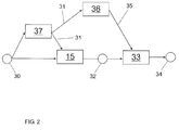
Figures 2 and3 . The left andright images 30 from theimaging apparatus 11, which here is a stereo imaging apparatus, are used to calculate adisparity image 31 by a disparityimage calculation code 37 having QM quality corresponding to a non-critical functional safety level. The disparityimage calculation code 37 may be executed for example in thepre-processing section 13, as described above, or in theprocessing device 14. TheQM disparity image 31 is used by the QMobject detection code 15 to detectobjects 32 in the surrounding of the motor vehicle, as described above. Theobject detection code 15 is executed by theprocessing device 14. Without the invention, the detectedobjects 32 would be used for evaluating and deciding the activation of thedriver assistance device 18. - As mentioned earlier, for safety critical applications it may not be sufficient to rely on detected objects having QM safety level, only. Therefore, according to the invention, a
gatekeeper code module 33, orgatekeeper module 33 for short, is provided in aprocessing device 19. Thegatekeeper code module 33 has a higher functional safety level, for example ASIL-B level, than theobject detection code 15. - Generally, the
gatekeeper module 33 lets pass only those detectedobjects 32 which fulfil a higher functional safety level as provided by theobject detection code 15. In other words, thegatekeeper module 33 does not generate new detected objects by itself, but only checks objects detected by theobject detection code 15, rejecting those which do not fulfil the higher functional safety standards of thegatekeeper module 33. This implies that the number of verified detectedobjects 34 verified by thegatekeeper code module 33 is equal or less the number of unverified detectedobjects 15. - The
gatekeeper code module 33 can be composed of a subset of theobject detection code 15, re-written in higher functional safety level quality, only. That is, exactly the same object detection as performed by theobject detection code 15 can be re-used in thegatekeeper code module 33, but only a few components of it are needed. This is because the goal of thefunctional safety module 33 is to find bugs in the QM code, and electronic errors in the processing hardware, only, both of which are easy to detect as they manifest in very large errors for the detected objects. In the above manner, the effort for producing thegatekeeper code module 33 can be strongly reduced. Thegatekeeper code module 33 can be significantly smaller than theobject detection code 15, for example less than half, like one third of theobject detection code 15. - The
gatekeeper module 33 advantageously evaluates the detected objects 32 using a verifieddisparity image 35. Theverification 36 of thedisparity image 31 yielding the verifieddisparity image 35 uses a verification code having a higher functional safety level, for example ASIL-B, than the unverifieddisparity calculation code 37. - The
verification 36 may be done in different manners. In a preferred embodiment, the disparity data is re-calculated for a number of rows in the image, for example for every other row, or every n-th row, or any other true subset of rows. If the recalculated disparity data matches the correspondingoriginal disparity data 31 within certain tolerances, the entireoriginal disparity image 31 may be considered safe under the higher functional safety level (like ASIL-B), and output as the verifieddisparity image 35 together with a safety flag indicating "safe". If the recalculated disparity data does not match the correspondingoriginal disparity data 31 within certain tolerances, the safety flag would be set to indicate "not safe". Therefore, the safety flag is preferably a binary flag. - It may also be possible to amend the
original disparity image 31 using the re-calculated disparity data, and to output the amended disparity image, together with the flag indicating "safe", as the verifiedimage 35. Other subsets than rows of theoriginal disparity image 31 may be re-calculated for performing theverification 36. Alternatively, the wholeoriginal disparity image 31 may be re-calculated in theverification 36. In this case, expediently the whole re-calculated disparity image is output as the verifieddisparity image 35. - Preferably, the
gatekeeper code module 33 is executed on adedicated hardware device 19, i.e. a separateelectronic processing device 19 different from theprocessing device 14 executing theobject detection code 15. The dedicated functionalsafety processing device 19 may be of a type mentioned above with respect to theprocessing device 14. Preferably, a smaller and lower-cost dedicated functionalsafety processing device 19 as compared to theprocessing device 14, i.e. one with less processing capacities, may be well sufficient for executing thegatekeeper code module 33. Theverification code 36 may preferably be executed on thesame processing device 19 as thegatekeeper code module 33 for similar reasons. - The operation of the
gatekeeper module 33 in a preferred embodiment is illustrated on the basis ofFigure 3 , showing an image captured by theimaging apparatus 11, where atruck 40 is present on the road in front of the ego vehicle. It may be assumed that thetruck 40 has been detected by the QMobject detection code 15, yielding an object bounding box 41. Thegatekeeper module 33 considers the verified depth image 35 (not shown) in the region of the object bounding box 41 provided by the QMobject detection code 15. In other words, the world coordinates of the detectedobject 32 are projected on the verifieddisparity image 35, resulting in a corresponding bounding box 41. - Specifically, the
gatekeeper module 33 defines a grid 42 in said bounding box 41, or covering said bounding box 41, or covering saidobject 40 within said bounding box 41. The grid 42 may be an n x m grid, where n > 1 and m > 1 are integers, definingn columns 43, m rows and n x m boxes 44. InFigure 3 , for example, n = 10. Thecolumns 43 form sub-areas in the language of the claims. Each box 44 is assigned dimensions, in particular a width and a height, corresponding to the maximum allowed position error for the detected object to be considered safe. - The
gatekeeper module 33 starts the verification at one end, for example the lower end, of onecolumn 43, for example theleftmost column 43. That is, the lowest box 44 in the leftmost column is compared against the longitudinal distance world coordinate at the part of the detected object corresponding to the box 44. If the longitudinal distance of the detected object in the box 44, as calculated by theobject detection code 15, matches the depth of the box 44 in the verifieddepth image 35 within predefined tolerances, the whole corresponding column 43 (here the leftmost column 43) is regarded safe. If not, the gatekeeper goes up one box in thesame column 43, here theleftmost column 43, and performs the same comparison again for that box, and so on. Generally, the first match of a box within a particular sub-area (here leftmost column 43) is regarded sufficient for considering the matching condition fulfilled for the wholeparticular sub-area 43. Therefore, upon the first match, thegatekeeper module 33 goes to thenext column 43, here the second-to-leftcolumn 43, and repeats the same process, starting with the lowest box 44 of the second-to-leftcolumn 43. - After all, if at least one box 44 in each
column 43 fulfils the matching condition, the detectedobject 40 is considered safe at the higher functional safety level, like ASIL-B. Thegatekeeper 33 lets thesafe object 34 pass such that safety-critical decisions like active braking or steering assistance may be based on it. - Furthermore, if only a very small number of
columns 43, like only onecolumn 43, fails to fulfil the matching condition (i.e., all boxes of thecolumn 43 fail to fulfil the matching condition), the detectedobject 40 may still be considered safe at the higher functional safety level, like ASIL-B. - On the other hand, if the number of
columns 43 which fail to fulfil the matching condition exceeds a predetermined number, like more than one failingcolumn 43, the detectedobject 40 is considered unsafe at the higher functional safety level, like ASIL-B. Thegatekeeper 33 rejects or discards theunsafe object 32, i.e. it cannot pass, such that safety-critical decisions like active braking or steering assistance cannot be based on it. - Generally, in the above procedure, a matching condition is considered fulfilled if a sufficient number of disparity pixels in the box 44 under consideration of the verified
depth image 35 have a sufficiently similar longitudinal distance as the detectedobject 32 has at the part of the detected object corresponding to the box 44.
Claims (15)
- A vision system (10) for a motor vehicle, comprising an imaging apparatus (11) adapted to capture images from a surrounding of the motor vehicle, and a processing device (14) adapted to execute an object detection code (15) to detect objects in the surrounding of the motor vehicle by processing images captured by said imaging apparatus (11) and to calculate for each detected object its longitudinal distance relative to the ego vehicle, characterized in that said vision system comprises a gatekeeper code module (33) having a higher functional safety level than said object detection code (15), said gatekeeper code module (33) taking as input objects (32) detected by said object detection code (15) and being adapted to evaluate if a depth or disparity image (35), in at least a part of an area covering the detected object (32), matches within given tolerances the longitudinal distance of the detected object (32) given by said object detection code (15).
- The vision system as claimed in claim 1, characterized in that said gatekeeper code module (33) uses a verified depth or disparity image (35) which has been verified by a verification code (36) having a higher functional safety level than said object detection code (15).
- The vision system as claimed in claim 2, characterized in that said verified depth or disparity image (35) is a depth or disparity image (31) calculated by a depth or disparity image calculation code (37) having a lower functional safety level than said gatekeeper code module (33), plus a safety flag indicating "safe" or "not safe" provided by said verification code (36).
- The vision system as claimed in any one of the preceding claims, characterized in that said verified depth or disparity image (35) is obtained by re-calculating depth or disparity data (31) from said depth or disparity image calculator (37) for a subset of the whole image, and to compare the re-calculated depth or disparity data with the original depth or disparity data (31).
- The vision system as claimed in any one of the preceding claims, characterized in that the intrinsic calibration, in particular the intrinsic yaw angle calibration, of said imaging apparatus (11) is verified to have at least the same functional safety level as said gatekeeper code module (33) and/or said verification code (36).
- The vision system as claimed in any one of the preceding claims, characterized in that said gatekeeper code module (33) is adapted to divide an area covering the detected object (40) into sub-areas (43), and to perform said matching evaluation in at least a part of said sub-areas (43).
- The vision system as claimed in claim 6, characterized in that a detected object is discarded if the matching condition is not fulfilled for a predetermined number of said sub-areas (43).
- The vision system as claimed in claim 6 or 7, characterized in that said sub-areas (43) are columns of a grid.
- The vision system as claimed in any one of claims 6 to 8, characterized in that said gatekeeper code module (33) is adapted to divide said sub-areas (43) into boxes (44), and to perform said matching evaluation in at least a part of said boxes (44).
- The vision system as claimed in claim 9, characterized in that said boxes (44) are defined by rows (43) and columns of said grid.
- The vision system as claimed in claim 9 or 10, characterized in that each box (44) has dimensions corresponding to a maximum allowed position error for the detected object (40) to be considered safe.
- The vision system as claimed in any one of claims 9 to 11, characterized in that the first match of a box (44) within a particular sub-area (43) is regarded sufficient for considering the matching condition fulfilled for that particular sub-area (43).
- The vision system as claimed in any one of the preceding claims, characterized in that a matching condition is considered fulfilled if a sufficient number of disparity pixels in the box (44) under consideration of the verified depth image (35) have a sufficiently similar longitudinal distance as the detected object (32) has at the part of the detected object corresponding to box (44).
- The vision system as claimed in any one of the preceding claims, characterized in that the gatekeeper code module (33), and preferably also the verification code (36), is executed on a dedicated electronic processing device (19).
- A vision method for a motor vehicle, comprising capturing images from a surrounding of the motor vehicle, and executing an object detection code (15) to detect objects in the surrounding of the motor vehicle by processing captured images and to calculate for each detected object its longitudinal distance relative to the ego vehicle, characterized by executing a gatekeeper code module (33) having a higher functional safety level than said object detection code (15), said gatekeeper code module (33) taking as input objects (32) detected by said object detection code (15), and evaluating if a depth or disparity image (35), in at least a part of an area covering the detected object (32), matches within given tolerances the longitudinal distance of the detected object (32) given by said object detection code (15).
Priority Applications (4)
| Application Number | Priority Date | Filing Date | Title |
|---|---|---|---|
| EP16182309.1A EP3279830B1 (en) | 2016-08-02 | 2016-08-02 | A vision system and method for a motor vehicle |
| JP2019502733A JP6763080B2 (en) | 2016-08-02 | 2017-07-27 | Automotive vision systems and methods |
| US16/322,349 US12277775B2 (en) | 2016-08-02 | 2017-07-27 | Vision system and method for a motor vehicle |
| PCT/EP2017/068965 WO2018024590A1 (en) | 2016-08-02 | 2017-07-27 | A vision system and method for a motor vehicle |
Applications Claiming Priority (1)
| Application Number | Priority Date | Filing Date | Title |
|---|---|---|---|
| EP16182309.1A EP3279830B1 (en) | 2016-08-02 | 2016-08-02 | A vision system and method for a motor vehicle |
Publications (2)
| Publication Number | Publication Date |
|---|---|
| EP3279830A1 true EP3279830A1 (en) | 2018-02-07 |
| EP3279830B1 EP3279830B1 (en) | 2020-10-28 |
Family
ID=56684465
Family Applications (1)
| Application Number | Title | Priority Date | Filing Date |
|---|---|---|---|
| EP16182309.1A Active EP3279830B1 (en) | 2016-08-02 | 2016-08-02 | A vision system and method for a motor vehicle |
Country Status (4)
| Country | Link |
|---|---|
| US (1) | US12277775B2 (en) |
| EP (1) | EP3279830B1 (en) |
| JP (1) | JP6763080B2 (en) |
| WO (1) | WO2018024590A1 (en) |
Cited By (3)
| Publication number | Priority date | Publication date | Assignee | Title |
|---|---|---|---|---|
| IT202400002265A1 (en) | 2024-02-02 | 2025-08-02 | Comm3000 S P A | SYSTEM AND METHOD FOR DETERMINING THE APPROACH OF AN OBJECT |
| EP4632684A1 (en) | 2024-04-11 | 2025-10-15 | Comm3000 S.p.A. | Method and system to assess the distance of an object framed by a camera |
| EP3683718B1 (en) * | 2019-01-18 | 2025-11-12 | Qualcomm Auto Ltd. | Driver assistance system and method for a motor vehicle |
Families Citing this family (1)
| Publication number | Priority date | Publication date | Assignee | Title |
|---|---|---|---|---|
| CN115690722A (en) * | 2022-09-14 | 2023-02-03 | 北京罗克维尔斯科技有限公司 | Pedestrian and cyclist detection frame matching method, device, equipment, medium and vehicle |
Citations (4)
| Publication number | Priority date | Publication date | Assignee | Title |
|---|---|---|---|---|
| US20080285799A1 (en) * | 2007-05-16 | 2008-11-20 | Institute Of Technology, National Defense University | Apparatus and method for detecting obstacle through stereovision |
| US20090195371A1 (en) * | 2003-12-15 | 2009-08-06 | Theodore Armand Camus | Method and Apparatus for Object Tracking Prior to Imminent Collision Detection |
| EP2219133A1 (en) | 2009-02-17 | 2010-08-18 | Autoliv Development AB | A method and system of automatically detecting objects in front of a motor vehicle |
| US20130030657A1 (en) * | 2011-07-25 | 2013-01-31 | GM Global Technology Operations LLC | Active safety control for vehicles |
Family Cites Families (24)
| Publication number | Priority date | Publication date | Assignee | Title |
|---|---|---|---|---|
| US5850475A (en) * | 1994-05-10 | 1998-12-15 | Fuji Xerox Co., Ltd. | Method and apparatus for dividing image area |
| JPH0830787A (en) * | 1994-05-10 | 1996-02-02 | Fuji Xerox Co Ltd | Image area dividing method and image area integrating method |
| US6825760B2 (en) * | 2003-03-31 | 2004-11-30 | Bellsouth Intellectual Property Corporation | Vehicle safety flag assembly with ignition override switch and method of operating the same |
| JP4380561B2 (en) * | 2004-04-16 | 2009-12-09 | 株式会社デンソー | Driving assistance device |
| DE102004035004A1 (en) * | 2004-07-20 | 2006-02-16 | Bayerische Motoren Werke Ag | Method for increasing the driving stability of a motor vehicle |
| US8583341B2 (en) * | 2008-02-11 | 2013-11-12 | Continental Teves Ag & Co. Ohg | Method for the open-loop and closed-loop control of traffic flow |
| DE102011086530A1 (en) * | 2010-11-19 | 2012-05-24 | Continental Teves Ag & Co. Ohg | Microprocessor system with fault-tolerant architecture |
| US20130100266A1 (en) * | 2011-10-25 | 2013-04-25 | Kenneth Edward Salsman | Method and apparatus for determination of object topology |
| DE112013000582B4 (en) * | 2012-01-16 | 2025-06-05 | Maxim Integrated Products, Inc. | Method and device for differential communication |
| DE102012208995B4 (en) * | 2012-05-29 | 2017-12-07 | pmdtechnologies ag | Time of flight camera system with data channel |
| JP5724955B2 (en) * | 2012-06-22 | 2015-05-27 | トヨタ自動車株式会社 | Object detection apparatus, information processing apparatus, and object detection method |
| US20130342365A1 (en) * | 2012-06-22 | 2013-12-26 | GM Global Technology Operations LLC | Alert systems and methods for a vehicle |
| US9432563B2 (en) * | 2012-08-08 | 2016-08-30 | Broadcom Corporation | Three-dimensional imaging through multi-image processing |
| DE102012215093A1 (en) * | 2012-08-24 | 2014-02-27 | Robert Bosch Gmbh | Driver assistance system and method for operating the driver assistance system |
| DE102012215343A1 (en) * | 2012-08-29 | 2014-05-28 | Continental Automotive Gmbh | Method for performing a safety function of a vehicle and system for carrying out the method |
| WO2014043641A1 (en) * | 2012-09-14 | 2014-03-20 | Pelican Imaging Corporation | Systems and methods for correcting user identified artifacts in light field images |
| US9066085B2 (en) * | 2012-12-13 | 2015-06-23 | Delphi Technologies, Inc. | Stereoscopic camera object detection system and method of aligning the same |
| US20160004535A1 (en) * | 2013-02-15 | 2016-01-07 | Alistair Robertson | Method of operating a multi-thread capable processor system, an automotive system comprising such multi-thread capable processor system, and a computer program product |
| US8892358B2 (en) * | 2013-03-14 | 2014-11-18 | Robert Bosch Gmbh | System and method for distortion correction in three-dimensional environment visualization |
| US9558563B1 (en) * | 2013-09-25 | 2017-01-31 | Amazon Technologies, Inc. | Determining time-of-fight measurement parameters |
| DE102014201271A1 (en) * | 2014-01-24 | 2015-07-30 | Robert Bosch Gmbh | A method and controller for detecting a change in a relative yaw angle within a stereo video system for a vehicle |
| FR3026515B1 (en) * | 2014-09-26 | 2017-12-01 | Valeo Systemes Thermiques | TRANSMITTING SYNCHRONOUS DATA THROUGH A SERIAL DATA BUS, IN PARTICULAR A SPI BUS |
| KR102400899B1 (en) * | 2015-07-15 | 2022-05-23 | 엘지전자 주식회사 | Mobile terminal and method for controlling the same |
| JP6864992B2 (en) * | 2016-04-28 | 2021-04-28 | 日立Astemo株式会社 | Vehicle control system verification device and vehicle control system |
-
2016
- 2016-08-02 EP EP16182309.1A patent/EP3279830B1/en active Active
-
2017
- 2017-07-27 US US16/322,349 patent/US12277775B2/en active Active
- 2017-07-27 JP JP2019502733A patent/JP6763080B2/en active Active
- 2017-07-27 WO PCT/EP2017/068965 patent/WO2018024590A1/en not_active Ceased
Patent Citations (4)
| Publication number | Priority date | Publication date | Assignee | Title |
|---|---|---|---|---|
| US20090195371A1 (en) * | 2003-12-15 | 2009-08-06 | Theodore Armand Camus | Method and Apparatus for Object Tracking Prior to Imminent Collision Detection |
| US20080285799A1 (en) * | 2007-05-16 | 2008-11-20 | Institute Of Technology, National Defense University | Apparatus and method for detecting obstacle through stereovision |
| EP2219133A1 (en) | 2009-02-17 | 2010-08-18 | Autoliv Development AB | A method and system of automatically detecting objects in front of a motor vehicle |
| US20130030657A1 (en) * | 2011-07-25 | 2013-01-31 | GM Global Technology Operations LLC | Active safety control for vehicles |
Cited By (4)
| Publication number | Priority date | Publication date | Assignee | Title |
|---|---|---|---|---|
| EP3683718B1 (en) * | 2019-01-18 | 2025-11-12 | Qualcomm Auto Ltd. | Driver assistance system and method for a motor vehicle |
| IT202400002265A1 (en) | 2024-02-02 | 2025-08-02 | Comm3000 S P A | SYSTEM AND METHOD FOR DETERMINING THE APPROACH OF AN OBJECT |
| EP4597475A1 (en) | 2024-02-02 | 2025-08-06 | Comm3000 S.p.A. | System and method for determining the approach of an object |
| EP4632684A1 (en) | 2024-04-11 | 2025-10-15 | Comm3000 S.p.A. | Method and system to assess the distance of an object framed by a camera |
Also Published As
| Publication number | Publication date |
|---|---|
| WO2018024590A1 (en) | 2018-02-08 |
| US12277775B2 (en) | 2025-04-15 |
| JP6763080B2 (en) | 2020-09-30 |
| EP3279830B1 (en) | 2020-10-28 |
| US20190180462A1 (en) | 2019-06-13 |
| JP2020504847A (en) | 2020-02-13 |
Similar Documents
| Publication | Publication Date | Title |
|---|---|---|
| EP2219133B1 (en) | A method and system of automatically detecting objects in front of a motor vehicle | |
| US11461595B2 (en) | Image processing apparatus and external environment recognition apparatus | |
| EP2246806B1 (en) | Vision method and system for automatically detecting objects in front of a motor vehicle | |
| US20090060273A1 (en) | System for evaluating an image | |
| US9592764B2 (en) | Redundant object detection for driver assistance systems | |
| US20170297488A1 (en) | Surround view camera system for object detection and tracking | |
| US20160314357A1 (en) | Method and Device for Monitoring an External Dimension of a Vehicle | |
| JP6571658B2 (en) | Method and apparatus for recognizing an object from depth-resolved image data | |
| EP3279830B1 (en) | A vision system and method for a motor vehicle | |
| EP3136288A1 (en) | Vision system and method for a motor vehicle | |
| US10748014B2 (en) | Processing device, object recognition apparatus, device control system, processing method, and computer-readable recording medium | |
| WO2017036927A1 (en) | Vision system for a motor vehicle and method of controlling a vision system | |
| EP3683718B1 (en) | Driver assistance system and method for a motor vehicle | |
| US20180201261A1 (en) | Method for checking the plausibility of a control decision for safety means | |
| EP3176725A1 (en) | Method and device for detecting a braking application of a vehicle | |
| EP2624169A1 (en) | Vision system and method for a motor vehicle | |
| EP2306366A1 (en) | Vision system and method for a motor vehicle | |
| EP3282394A1 (en) | A vision system and method for a motor vehicle | |
| EP3474182B1 (en) | A vision system and method for autonomous driving and/or driver assistance in a motor vehicle | |
| EP3291133B1 (en) | Vision system and method for a motor vehicle | |
| EP3779770A1 (en) | A stereo vision system and method for a motor vehicle | |
| Byun et al. | An effective pedestrian detection method for driver assistance system | |
| EP3522068A1 (en) | A vision system and method for autonomous driving and/or driver assistance in a motor vehicle | |
| EP3671532A1 (en) | Driver assistance system and method for a motor vehicle | |
| EP3306521A1 (en) | Stereo vision system and method for a motor vehicle |
Legal Events
| Date | Code | Title | Description |
|---|---|---|---|
| PUAI | Public reference made under article 153(3) epc to a published international application that has entered the european phase |
Free format text: ORIGINAL CODE: 0009012 |
|
| STAA | Information on the status of an ep patent application or granted ep patent |
Free format text: STATUS: THE APPLICATION HAS BEEN PUBLISHED |
|
| AK | Designated contracting states |
Kind code of ref document: A1 Designated state(s): AL AT BE BG CH CY CZ DE DK EE ES FI FR GB GR HR HU IE IS IT LI LT LU LV MC MK MT NL NO PL PT RO RS SE SI SK SM TR |
|
| AX | Request for extension of the european patent |
Extension state: BA ME |
|
| STAA | Information on the status of an ep patent application or granted ep patent |
Free format text: STATUS: REQUEST FOR EXAMINATION WAS MADE |
|
| 17P | Request for examination filed |
Effective date: 20180726 |
|
| RBV | Designated contracting states (corrected) |
Designated state(s): AL AT BE BG CH CY CZ DE DK EE ES FI FR GB GR HR HU IE IS IT LI LT LU LV MC MK MT NL NO PL PT RO RS SE SI SK SM TR |
|
| RAP1 | Party data changed (applicant data changed or rights of an application transferred) |
Owner name: VEONEER SWEDEN AB |
|
| STAA | Information on the status of an ep patent application or granted ep patent |
Free format text: STATUS: EXAMINATION IS IN PROGRESS |
|
| 17Q | First examination report despatched |
Effective date: 20190306 |
|
| GRAP | Despatch of communication of intention to grant a patent |
Free format text: ORIGINAL CODE: EPIDOSNIGR1 |
|
| STAA | Information on the status of an ep patent application or granted ep patent |
Free format text: STATUS: GRANT OF PATENT IS INTENDED |
|
| INTG | Intention to grant announced |
Effective date: 20200520 |
|
| GRAS | Grant fee paid |
Free format text: ORIGINAL CODE: EPIDOSNIGR3 |
|
| GRAA | (expected) grant |
Free format text: ORIGINAL CODE: 0009210 |
|
| STAA | Information on the status of an ep patent application or granted ep patent |
Free format text: STATUS: THE PATENT HAS BEEN GRANTED |
|
| AK | Designated contracting states |
Kind code of ref document: B1 Designated state(s): AL AT BE BG CH CY CZ DE DK EE ES FI FR GB GR HR HU IE IS IT LI LT LU LV MC MK MT NL NO PL PT RO RS SE SI SK SM TR |
|
| REG | Reference to a national code |
Ref country code: GB Ref legal event code: FG4D |
|
| REG | Reference to a national code |
Ref country code: CH Ref legal event code: EP |
|
| REG | Reference to a national code |
Ref country code: AT Ref legal event code: REF Ref document number: 1328948 Country of ref document: AT Kind code of ref document: T Effective date: 20201115 |
|
| REG | Reference to a national code |
Ref country code: DE Ref legal event code: R096 Ref document number: 602016046580 Country of ref document: DE |
|
| REG | Reference to a national code |
Ref country code: IE Ref legal event code: FG4D |
|
| REG | Reference to a national code |
Ref country code: AT Ref legal event code: MK05 Ref document number: 1328948 Country of ref document: AT Kind code of ref document: T Effective date: 20201028 |
|
| REG | Reference to a national code |
Ref country code: NL Ref legal event code: MP Effective date: 20201028 |
|
| PG25 | Lapsed in a contracting state [announced via postgrant information from national office to epo] |
Ref country code: PT Free format text: LAPSE BECAUSE OF FAILURE TO SUBMIT A TRANSLATION OF THE DESCRIPTION OR TO PAY THE FEE WITHIN THE PRESCRIBED TIME-LIMIT Effective date: 20210301 Ref country code: RS Free format text: LAPSE BECAUSE OF FAILURE TO SUBMIT A TRANSLATION OF THE DESCRIPTION OR TO PAY THE FEE WITHIN THE PRESCRIBED TIME-LIMIT Effective date: 20201028 Ref country code: NL Free format text: LAPSE BECAUSE OF FAILURE TO SUBMIT A TRANSLATION OF THE DESCRIPTION OR TO PAY THE FEE WITHIN THE PRESCRIBED TIME-LIMIT Effective date: 20201028 Ref country code: NO Free format text: LAPSE BECAUSE OF FAILURE TO SUBMIT A TRANSLATION OF THE DESCRIPTION OR TO PAY THE FEE WITHIN THE PRESCRIBED TIME-LIMIT Effective date: 20210128 Ref country code: FI Free format text: LAPSE BECAUSE OF FAILURE TO SUBMIT A TRANSLATION OF THE DESCRIPTION OR TO PAY THE FEE WITHIN THE PRESCRIBED TIME-LIMIT Effective date: 20201028 Ref country code: GR Free format text: LAPSE BECAUSE OF FAILURE TO SUBMIT A TRANSLATION OF THE DESCRIPTION OR TO PAY THE FEE WITHIN THE PRESCRIBED TIME-LIMIT Effective date: 20210129 |
|
| REG | Reference to a national code |
Ref country code: LT Ref legal event code: MG4D |
|
| PG25 | Lapsed in a contracting state [announced via postgrant information from national office to epo] |
Ref country code: ES Free format text: LAPSE BECAUSE OF FAILURE TO SUBMIT A TRANSLATION OF THE DESCRIPTION OR TO PAY THE FEE WITHIN THE PRESCRIBED TIME-LIMIT Effective date: 20201028 Ref country code: AT Free format text: LAPSE BECAUSE OF FAILURE TO SUBMIT A TRANSLATION OF THE DESCRIPTION OR TO PAY THE FEE WITHIN THE PRESCRIBED TIME-LIMIT Effective date: 20201028 Ref country code: IS Free format text: LAPSE BECAUSE OF FAILURE TO SUBMIT A TRANSLATION OF THE DESCRIPTION OR TO PAY THE FEE WITHIN THE PRESCRIBED TIME-LIMIT Effective date: 20210228 Ref country code: PL Free format text: LAPSE BECAUSE OF FAILURE TO SUBMIT A TRANSLATION OF THE DESCRIPTION OR TO PAY THE FEE WITHIN THE PRESCRIBED TIME-LIMIT Effective date: 20201028 Ref country code: SE Free format text: LAPSE BECAUSE OF FAILURE TO SUBMIT A TRANSLATION OF THE DESCRIPTION OR TO PAY THE FEE WITHIN THE PRESCRIBED TIME-LIMIT Effective date: 20201028 Ref country code: LV Free format text: LAPSE BECAUSE OF FAILURE TO SUBMIT A TRANSLATION OF THE DESCRIPTION OR TO PAY THE FEE WITHIN THE PRESCRIBED TIME-LIMIT Effective date: 20201028 Ref country code: BG Free format text: LAPSE BECAUSE OF FAILURE TO SUBMIT A TRANSLATION OF THE DESCRIPTION OR TO PAY THE FEE WITHIN THE PRESCRIBED TIME-LIMIT Effective date: 20210128 |
|
| PG25 | Lapsed in a contracting state [announced via postgrant information from national office to epo] |
Ref country code: HR Free format text: LAPSE BECAUSE OF FAILURE TO SUBMIT A TRANSLATION OF THE DESCRIPTION OR TO PAY THE FEE WITHIN THE PRESCRIBED TIME-LIMIT Effective date: 20201028 |
|
| REG | Reference to a national code |
Ref country code: DE Ref legal event code: R097 Ref document number: 602016046580 Country of ref document: DE |
|
| PG25 | Lapsed in a contracting state [announced via postgrant information from national office to epo] |
Ref country code: LT Free format text: LAPSE BECAUSE OF FAILURE TO SUBMIT A TRANSLATION OF THE DESCRIPTION OR TO PAY THE FEE WITHIN THE PRESCRIBED TIME-LIMIT Effective date: 20201028 Ref country code: SM Free format text: LAPSE BECAUSE OF FAILURE TO SUBMIT A TRANSLATION OF THE DESCRIPTION OR TO PAY THE FEE WITHIN THE PRESCRIBED TIME-LIMIT Effective date: 20201028 Ref country code: CZ Free format text: LAPSE BECAUSE OF FAILURE TO SUBMIT A TRANSLATION OF THE DESCRIPTION OR TO PAY THE FEE WITHIN THE PRESCRIBED TIME-LIMIT Effective date: 20201028 Ref country code: EE Free format text: LAPSE BECAUSE OF FAILURE TO SUBMIT A TRANSLATION OF THE DESCRIPTION OR TO PAY THE FEE WITHIN THE PRESCRIBED TIME-LIMIT Effective date: 20201028 Ref country code: SK Free format text: LAPSE BECAUSE OF FAILURE TO SUBMIT A TRANSLATION OF THE DESCRIPTION OR TO PAY THE FEE WITHIN THE PRESCRIBED TIME-LIMIT Effective date: 20201028 Ref country code: RO Free format text: LAPSE BECAUSE OF FAILURE TO SUBMIT A TRANSLATION OF THE DESCRIPTION OR TO PAY THE FEE WITHIN THE PRESCRIBED TIME-LIMIT Effective date: 20201028 |
|
| PG25 | Lapsed in a contracting state [announced via postgrant information from national office to epo] |
Ref country code: DK Free format text: LAPSE BECAUSE OF FAILURE TO SUBMIT A TRANSLATION OF THE DESCRIPTION OR TO PAY THE FEE WITHIN THE PRESCRIBED TIME-LIMIT Effective date: 20201028 |
|
| PLBE | No opposition filed within time limit |
Free format text: ORIGINAL CODE: 0009261 |
|
| STAA | Information on the status of an ep patent application or granted ep patent |
Free format text: STATUS: NO OPPOSITION FILED WITHIN TIME LIMIT |
|
| 26N | No opposition filed |
Effective date: 20210729 |
|
| PG25 | Lapsed in a contracting state [announced via postgrant information from national office to epo] |
Ref country code: AL Free format text: LAPSE BECAUSE OF FAILURE TO SUBMIT A TRANSLATION OF THE DESCRIPTION OR TO PAY THE FEE WITHIN THE PRESCRIBED TIME-LIMIT Effective date: 20201028 Ref country code: IT Free format text: LAPSE BECAUSE OF FAILURE TO SUBMIT A TRANSLATION OF THE DESCRIPTION OR TO PAY THE FEE WITHIN THE PRESCRIBED TIME-LIMIT Effective date: 20201028 |
|
| REG | Reference to a national code |
Ref country code: DE Ref legal event code: R079 Ref document number: 602016046580 Country of ref document: DE Free format text: PREVIOUS MAIN CLASS: G06K0009000000 Ipc: G06V0010000000 |
|
| PG25 | Lapsed in a contracting state [announced via postgrant information from national office to epo] |
Ref country code: SI Free format text: LAPSE BECAUSE OF FAILURE TO SUBMIT A TRANSLATION OF THE DESCRIPTION OR TO PAY THE FEE WITHIN THE PRESCRIBED TIME-LIMIT Effective date: 20201028 |
|
| REG | Reference to a national code |
Ref country code: CH Ref legal event code: PL |
|
| PG25 | Lapsed in a contracting state [announced via postgrant information from national office to epo] |
Ref country code: MC Free format text: LAPSE BECAUSE OF FAILURE TO SUBMIT A TRANSLATION OF THE DESCRIPTION OR TO PAY THE FEE WITHIN THE PRESCRIBED TIME-LIMIT Effective date: 20201028 |
|
| REG | Reference to a national code |
Ref country code: BE Ref legal event code: MM Effective date: 20210831 |
|
| GBPC | Gb: european patent ceased through non-payment of renewal fee |
Effective date: 20210802 |
|
| PG25 | Lapsed in a contracting state [announced via postgrant information from national office to epo] |
Ref country code: LI Free format text: LAPSE BECAUSE OF NON-PAYMENT OF DUE FEES Effective date: 20210831 Ref country code: CH Free format text: LAPSE BECAUSE OF NON-PAYMENT OF DUE FEES Effective date: 20210831 |
|
| PG25 | Lapsed in a contracting state [announced via postgrant information from national office to epo] |
Ref country code: IS Free format text: LAPSE BECAUSE OF FAILURE TO SUBMIT A TRANSLATION OF THE DESCRIPTION OR TO PAY THE FEE WITHIN THE PRESCRIBED TIME-LIMIT Effective date: 20210228 Ref country code: LU Free format text: LAPSE BECAUSE OF NON-PAYMENT OF DUE FEES Effective date: 20210802 |
|
| PG25 | Lapsed in a contracting state [announced via postgrant information from national office to epo] |
Ref country code: IE Free format text: LAPSE BECAUSE OF NON-PAYMENT OF DUE FEES Effective date: 20210802 Ref country code: GB Free format text: LAPSE BECAUSE OF NON-PAYMENT OF DUE FEES Effective date: 20210802 Ref country code: BE Free format text: LAPSE BECAUSE OF NON-PAYMENT OF DUE FEES Effective date: 20210831 |
|
| REG | Reference to a national code |
Ref country code: DE Ref legal event code: R082 Ref document number: 602016046580 Country of ref document: DE Representative=s name: BARDEHLE PAGENBERG PARTNERSCHAFT MBB PATENTANW, DE |
|
| REG | Reference to a national code |
Ref country code: DE Ref legal event code: R081 Ref document number: 602016046580 Country of ref document: DE Owner name: ARRIVER SOFTWARE AB, SE Free format text: FORMER OWNER: VEONEER SWEDEN AB, VARGARDA, SE Ref country code: DE Ref legal event code: R081 Ref document number: 602016046580 Country of ref document: DE Owner name: QUALCOMM AUTO LTD., GB Free format text: FORMER OWNER: VEONEER SWEDEN AB, VARGARDA, SE |
|
| PG25 | Lapsed in a contracting state [announced via postgrant information from national office to epo] |
Ref country code: HU Free format text: LAPSE BECAUSE OF FAILURE TO SUBMIT A TRANSLATION OF THE DESCRIPTION OR TO PAY THE FEE WITHIN THE PRESCRIBED TIME-LIMIT; INVALID AB INITIO Effective date: 20160802 |
|
| PG25 | Lapsed in a contracting state [announced via postgrant information from national office to epo] |
Ref country code: CY Free format text: LAPSE BECAUSE OF FAILURE TO SUBMIT A TRANSLATION OF THE DESCRIPTION OR TO PAY THE FEE WITHIN THE PRESCRIBED TIME-LIMIT Effective date: 20201028 |
|
| PG25 | Lapsed in a contracting state [announced via postgrant information from national office to epo] |
Ref country code: MK Free format text: LAPSE BECAUSE OF FAILURE TO SUBMIT A TRANSLATION OF THE DESCRIPTION OR TO PAY THE FEE WITHIN THE PRESCRIBED TIME-LIMIT Effective date: 20201028 |
|
| PG25 | Lapsed in a contracting state [announced via postgrant information from national office to epo] |
Ref country code: MT Free format text: LAPSE BECAUSE OF FAILURE TO SUBMIT A TRANSLATION OF THE DESCRIPTION OR TO PAY THE FEE WITHIN THE PRESCRIBED TIME-LIMIT Effective date: 20201028 |
|
| REG | Reference to a national code |
Ref country code: DE Ref legal event code: R081 Ref document number: 602016046580 Country of ref document: DE Owner name: QUALCOMM AUTO LTD., GB Free format text: FORMER OWNER: ARRIVER SOFTWARE AB, LINKOEPING, SE |
|
| PGFP | Annual fee paid to national office [announced via postgrant information from national office to epo] |
Ref country code: DE Payment date: 20250709 Year of fee payment: 10 |
|
| PGFP | Annual fee paid to national office [announced via postgrant information from national office to epo] |
Ref country code: FR Payment date: 20250709 Year of fee payment: 10 |
|
| PG25 | Lapsed in a contracting state [announced via postgrant information from national office to epo] |
Ref country code: TR Free format text: LAPSE BECAUSE OF FAILURE TO SUBMIT A TRANSLATION OF THE DESCRIPTION OR TO PAY THE FEE WITHIN THE PRESCRIBED TIME-LIMIT Effective date: 20201028 |