EP3279757A1 - System and method for detecting faults and/or for providing optimization measures to enhance the performance of one or more buildings - Google Patents
System and method for detecting faults and/or for providing optimization measures to enhance the performance of one or more buildings Download PDFInfo
- Publication number
- EP3279757A1 EP3279757A1 EP16182491.7A EP16182491A EP3279757A1 EP 3279757 A1 EP3279757 A1 EP 3279757A1 EP 16182491 A EP16182491 A EP 16182491A EP 3279757 A1 EP3279757 A1 EP 3279757A1
- Authority
- EP
- European Patent Office
- Prior art keywords
- data
- buildings
- performance
- tree
- rules
- Prior art date
- Legal status (The legal status is an assumption and is not a legal conclusion. Google has not performed a legal analysis and makes no representation as to the accuracy of the status listed.)
- Granted
Links
Images







Classifications
-
- G—PHYSICS
- G05—CONTROLLING; REGULATING
- G05B—CONTROL OR REGULATING SYSTEMS IN GENERAL; FUNCTIONAL ELEMENTS OF SUCH SYSTEMS; MONITORING OR TESTING ARRANGEMENTS FOR SUCH SYSTEMS OR ELEMENTS
- G05B23/00—Testing or monitoring of control systems or parts thereof
- G05B23/02—Electric testing or monitoring
- G05B23/0205—Electric testing or monitoring by means of a monitoring system capable of detecting and responding to faults
- G05B23/0218—Electric testing or monitoring by means of a monitoring system capable of detecting and responding to faults characterised by the fault detection method dealing with either existing or incipient faults
- G05B23/0243—Electric testing or monitoring by means of a monitoring system capable of detecting and responding to faults characterised by the fault detection method dealing with either existing or incipient faults model based detection method, e.g. first-principles knowledge model
- G05B23/0245—Electric testing or monitoring by means of a monitoring system capable of detecting and responding to faults characterised by the fault detection method dealing with either existing or incipient faults model based detection method, e.g. first-principles knowledge model based on a qualitative model, e.g. rule based; if-then decisions
- G05B23/0251—Abstraction hierarchy, e.g. "complex systems", i.e. system is divided in subsystems, subsystems are monitored and results are combined to decide on status of whole system
-
- G—PHYSICS
- G05—CONTROLLING; REGULATING
- G05B—CONTROL OR REGULATING SYSTEMS IN GENERAL; FUNCTIONAL ELEMENTS OF SUCH SYSTEMS; MONITORING OR TESTING ARRANGEMENTS FOR SUCH SYSTEMS OR ELEMENTS
- G05B19/00—Program-control systems
- G05B19/02—Program-control systems electric
- G05B19/418—Total factory control, i.e. centrally controlling a plurality of machines, e.g. direct or distributed numerical control [DNC], flexible manufacturing systems [FMS], integrated manufacturing systems [IMS] or computer integrated manufacturing [CIM]
- G05B19/41835—Total factory control, i.e. centrally controlling a plurality of machines, e.g. direct or distributed numerical control [DNC], flexible manufacturing systems [FMS], integrated manufacturing systems [IMS] or computer integrated manufacturing [CIM] characterised by program execution
-
- G—PHYSICS
- G05—CONTROLLING; REGULATING
- G05B—CONTROL OR REGULATING SYSTEMS IN GENERAL; FUNCTIONAL ELEMENTS OF SUCH SYSTEMS; MONITORING OR TESTING ARRANGEMENTS FOR SUCH SYSTEMS OR ELEMENTS
- G05B13/00—Adaptive control systems, i.e. systems automatically adjusting themselves to have a performance which is optimum according to some preassigned criterion
- G05B13/02—Adaptive control systems, i.e. systems automatically adjusting themselves to have a performance which is optimum according to some preassigned criterion electric
- G05B13/04—Adaptive control systems, i.e. systems automatically adjusting themselves to have a performance which is optimum according to some preassigned criterion electric involving the use of models or simulators
- G05B13/041—Adaptive control systems, i.e. systems automatically adjusting themselves to have a performance which is optimum according to some preassigned criterion electric involving the use of models or simulators in which a variable is automatically adjusted to optimise the performance
-
- G—PHYSICS
- G06—COMPUTING OR CALCULATING; COUNTING
- G06F—ELECTRIC DIGITAL DATA PROCESSING
- G06F16/00—Information retrieval; Database structures therefor; File system structures therefor
- G06F16/20—Information retrieval; Database structures therefor; File system structures therefor of structured data, e.g. relational data
- G06F16/22—Indexing; Data structures therefor; Storage structures
- G06F16/2228—Indexing structures
- G06F16/2246—Trees, e.g. B+trees
-
- G—PHYSICS
- G06—COMPUTING OR CALCULATING; COUNTING
- G06F—ELECTRIC DIGITAL DATA PROCESSING
- G06F16/00—Information retrieval; Database structures therefor; File system structures therefor
- G06F16/20—Information retrieval; Database structures therefor; File system structures therefor of structured data, e.g. relational data
- G06F16/25—Integrating or interfacing systems involving database management systems
- G06F16/252—Integrating or interfacing systems involving database management systems between a Database Management System and a front-end application
Definitions
- the present invention relates generally to the technical field of building management systems or building automation systems.
- the present invention relates to systems and methods for detecting faults and/or for providing optimization measures to enhance the performance of one or more buildings, especially the building automation equipment of the one or more buildings.
- the management of energy by a building automation system is the combination of actions taken to maximize energy usage efficiency and optimize energy supply to lower energy costs without sacrificing occupant needs and comfort.
- actions may include reducing end use of energy consuming equipment, increasing efficiency of equipment, eliminating wasted energy, finding less costly alternative energy sources, minimizing procurement costs, or detecting faults in building equipment.
- Equipment faults in buildings cause undesirable effects such as e.g. increasing the energy consumption or decreasing the lifespan of equipment.
- various methods of fault detection including statistical analysis methods and methods for statistical process control. These methods are often cumbersome to operate or use in or with a BAS, or they require programming experience.
- the object of the invention is to provide methods and systems for fault detection and diagnosis which are easy to operate by building operators.
- This object will be achieved by a computer-facilitated method for detecting faults, providing optimization measures, or both of the foregoing to enhance the performance of one or more buildings, including building automation equipment disposed in relation to the one or more buildings, the method comprising:
- script builder tool for generating executable code modules for detecting faults, providing optimization measures, or both of the foregoing to enhance the performance of one or more buildings
- the script builder tool comprising:
- Smart buildings generate a lot of traffic and an increasingly large amount of data. Therefore, there is a focus on the performance and optimization of building systems, respectively sub-systems (e.g. air distribution, cooling, heating, lighting) and individual technical infrastructure or equipments within these systems, like air handling units, chillers, boilers, etc.
- sub-systems e.g. air distribution, cooling, heating, lighting
- individual technical infrastructure or equipments within these systems like air handling units, chillers, boilers, etc.
- This requires the analysis of huge amounts of time series data (e.g. performance data) and their timely correlation by sophisticated rules to find inefficiencies in operation, deviation from control strategy, or negative impact on the building comfort, for example.
- System engineers or energy engineers need to analyze the data frequently in order to measure, find faults, or give advice to improve the performance of equipments, sub-systems, systems, or buildings.
- a user e.g. building owner, building operator
- a user therefore is to be expected to know about the individual setup of equipments in terms of its specific type and associated parameters, the available data points, operational schedules, etc.
- the user needs to align or normalize the data point time series regarding the required analysis granularity, as the raw data granularity can vary from data point to data point, e.g. time series data can be available as 1-, 5- or 15-minute samples, and the analysis should be advantageously performed in 15-minute intervals, which would require the compression of the higher granular time series to 15-minute values based on a certain compress function, like Sum/Average/Min/Max.
- the user needs also to ensure that the units of measure of the data series fit to each other across the analysis scenario to perform correct calculations.
- the actual analysis can start by defining the logic the user wants to apply to the data to detect the anomalies or patterns he is looking for.
- This logic can be called a rule, and a collection of several rules e.g. for a certain type of system or equipment can be put together in a script.
- the execution of rules can be limited to certain types of assets (buildings, systems, equipments etc.), or the execution of rules can be designed to a certain asset.
- the script builder tool advantageously allows the assignment of probable causes (means defects or faults) and potential actions (optimization or improvement measures) that could be taken on a per rule basis.
- the scripts or rules can be executed even by occasional users for the whole portfolio of buildings, systems, sub-systems, or equipments of a customer at once, and they can be applied to different customers without having to be recreated or re-generated.
- the results can be presented in various forms like a navigation tree showing aggregated results, an overview grid and/or graphically.
- the script builder tool provides functionality to configure the published data on a per script or rule basis comprising the definition of aggregated information like the number of fault occurrences and durations and the ability to assign the accompanying trend data series which could help the user to better understand the actual conditions when the fault occurred.
- Figure 1 illustrates a first exemplary schematic overview diagram of a system S1, especially a FDD-system (Fault Detection and Diagnosis System) for detecting faults and/or providing optimization measures to enhance the performance of one or more buildings B.
- the exemplary system S1 comprises a database DB storing a data model comprising asset AD and performance data PD of the one or more buildings B, wherein the data model is represented in one or more hierarchical tree-structures.
- the exemplary system S1 further comprises a user interface UI (advantageously a menu-driven user interface UI) for configuring rules for analyzing the asset AD and the performance data PD in respect to the building performance of the one or more buildings B.
- UI a user interface UI
- the rules referring to data point mappings, parameters, asset data mappings, runtime settings, or schedules which are configured by user input using logical operators and defined functions.
- the rules are created and configured using an Input Unit IU comprising keyboard, mouse, etc., and the user interface UI.
- the user interface UI provides input fields IPF1 - IPF3 for creating and configuring the rules by using logical operators (e.g. "AND”, “for”, “EQUAL”, “GREATER”, “SMALLER”) and defined functions, e.g. predefined macros or subroutines.
- the exemplary system S1 furthermore comprises a processing unit PU for generating executable code modules (e.g. dll, "Dynamic Link Libraries") at runtime based on the user configured rules.
- the rules are executed by a runtime system traversing the tree-structures of the data model.
- the module code generator CG comprises a rule engine for checking the syntax of the rules and for assembling the rules to an executable script.
- the module code generator CG further comprises a module for code generation to automatically generate executable code modules (e.g. dll files or exe files) to run the script on the respective runtime system RS.
- the runtime system RS is configured to run the generated code modules (e.g.
- the processing unit PU can be for instance a Personal Computer (PC) or a Workstation.
- the processing unit PU is equipped and configured with appropriate hardware and software components.
- the PU can also be implemented in a cloud computing environment.
- the database DB which stores the data model comprising asset AD and performance data PD of the one or more buildings B can be integrated in a memory (e.g. drive or flash memory) of the processing unit PU.
- the database DB could also be stored in an in an In-Memory-Database of the processing unit PU. Storing the database DB an In-Memory-Database of the processing unit PU is especially advantageous for applications which require very high response times for providing faults to the user.
- the processing unit PU has access to the database DB via an adequate communication interface (e.g. a wireless or radio connection).
- the database DB could also be implemented in a cloud. This allows the sharing of the resource database DB to more than one processing units PU.
- a provider of the resource database DB (including the respective data model comprising asset AD data and performance PD data of one or more buildings B) could provide the content of the database DB for customer as software-as-a-service.
- the content of the database DB means the data model comprising asset AD and performance data PD of the one or more buildings B is arranged in one or more tree-structures each having a plurality of nodes and a plurality of leaves.
- the nodes of the tree-structures represent asset data AD and the leaves of the tree-structures represent performance data PD of the one or more buildings B.
- the performance data PD are represented in each case by data points, the data points comprising time series of measured or derived field values and meta information of the technical equipment (e.g. HVAC equipment) of the one or more buildings B.
- the asset data AD of the one or more buildings B comprise information regarding the technical infrastructure or technical equipment for climate control (HVAC), and/or access control, and/or energy supply and control, and/or security and/or fire safety of the one or more buildings B.
- the asset data AD of the one or more buildings B include but are not limited to one or more of the following: passive data (e.g. types and quantities of employed systems, subsystems, components equipped in the one or more buildings B), setting data, weather data, energy tariff rates (e.g. energy prices) or emission factors (e.g. CO2). Since asset data AD of a building B do not change very frequently, the asset data AD can be submitted to the database DB for instance by an update batch (e.g. daily, weekly, monthly) or if the building B is equipped with a piece of newly installed or changed infrastructure device.
- an update batch e.g. daily, weekly, monthly
- the performance data PD of the one or more buildings B comprise: building control system data, and/or electricity metering data, and/or heat metering data, and/or water metering data, and/or temperature data, and/or humidity data, and/or pressure data, and/or events, and/or alarms.
- This listing is not limited.
- the performance data PD regarding the technical equipment have to be monitored permanently to derive reliable conclusions regarding the detection faults or defects of the technical equipment in a building B.
- the performance data PD are submitted to the database DB in a resolution in between 1 and 60 minutes, in particular in a resolution in between 1 and 15 minutes. This enables a fast response to time critical requests or time critical applications in providing detected faults F and/or optimization measures OM for a customer.
- the asset AD and the performance data PD of the one or more buildings B can be submitted to the database advantageously by a wireless communication connection (e.g. adequate radio connection). Adequate wired communication connections can also be used.
- a wireless communication connection e.g. adequate radio connection.
- Adequate wired communication connections can also be used.
- the exemplary system S1 further comprises an output unit OU for outputting detected faults F and/or providing optimization measures OM regarding the one or more buildings B.
- the output unit OU could be a display of a computer monitor, a display of a tablet computer, a display of a handheld device (e.g. Smartphone), or the display of a monitor station of a building automation system or building management system (e.g. Desigo CC).
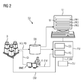
- Figure 2 illustrates a second exemplary schematic overview diagram of a system S2 for detecting faults F and/or providing optimization measures OM to enhance the performance of one or more buildings B.
- the system S2 illustrated in figure 2 is additionally connected or integrated to a building management system BMS.
- a building management system BMS controls and/or monitors the technical equipment (e.g. mechanical or electrical devices) and sub-systems (e.g. power systems, security systems, heating systems, ventilation systems, or evacuation systems) of the one or more buildings B.
- the detected faults F and/or the optimization measures OM are inputted directly (online) into the building management system BMS for operating the one or more buildings B.
- the detected faults F and/or the optimization measures OM can also be reported offline (e.g. as a daily update batch) into the building management system BMS. Based on the detected faults F and/or the optimization measures OM the building management system BMS can derived or create improvement data ID in an adequate granularity for the respective technical infrastructure affected by the detected faults F or optimization measures OM.
- the optimization measures OM are inputted directly to the respective affected technical automation equipment of the one or more buildings B.
- suitable communication means e.g. Internet or radio communication
- To engage directly online or in real time to recognized affected or defect technical automation equipment of the one or more buildings B is especially advantageous if the derived optimization measures OM are easily to implement, e.g. switching on or off of a device or sub-system in the one or more buildings B.
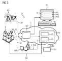
- Figure 3 illustrates a third exemplary schematic overview diagram of a system S3 for detecting faults and/or providing optimization measures to enhance the performance of one or more buildings B that depicts various aspects and embodiments of the present invention, especially the integration of the processing unit PU and the database DB in a cloud C.
- the infrastructure of cloud C is implemented Internet-based and the database DB is realized as remotely accessible database server or file server.
- the processing unit PU is realized as a server computer offering diagnosis services to the respective clients (e.g. building operators, building owners, facility manager).
- the processing unit PU and the database DB of the FDD system S3 can be integrated or be part of a service platform system which is realized as a cloud based platform, wherein the infrastructure and/or the platform and/or the software programs (or parts of the infrastructure or of the platform or of the software) are provided by a cloud service provider.
- the database DB comprises not only asset data AD and performance data PD of the one or more buildings B, but also energy prices EP provided by a utility or an energy supplier ES.
- the database DB comprises also weather data, weather forecast data, or data regarding consumable resources (e.g. water, fuel) utilized in the one or more buildings B.
- the weather data can be provided by a weather data or weather forecast provider. This can be a private and/or a public provider.
- Figure 4 illustrates a first exemplary database DB storing a first exemplary data model DM1 comprising asset and performance data of the one or more buildings.
- the data model DM1 is represented in one or more hierarchical tree-structures, wherein the nodes AHU, AD1, AD2 of the tree-structures represent asset data and the leaves of the tree-structures represent performance data of the one or more buildings.
- the performance data PD1 - PD6 of the technical equipment of the one or more buildings are represented in each case by data points, wherein the data points comprising time series of measured or derived field values and meta information of the technical equipment.
- the exemplary data model DM1 shows a tree-structure for an exemplary schematic air handling unit AHU equipped in a building B.
- the illustrated exemplary schematic air handling unit AHU comprises two exemplary subsystems. For instance a heating sub-system (e.g. a boiler) and a cooling sub-system (e.g. a chiller).
- the heating sub-system and the cooling sub-system are represented in the data model DM1 as asset data AD1 respectively AD2.
- asset data AD1 does represent the heating sub-system
- asset data AD2 the cooling sub-system of the air handling unit AHU.
- To the asset data AD1 representing the heating sub-system the performance data PD1 - PD3 are assigned.
- the performance data PD1 - PD3 represent exemplary data points of the heating sub-system of the air handling unit AHU.
- the data points comprise time series of measured or derived field values and meta information of the exemplary heating sub-system of the air handling unit AHU.
- the performance data PD1 - PD3 of the heating sub-system AD1 can be e.g. air temperature, air velocity, and air humidity.
- the performance data PD4 - PD6 assigned to asset data AD2 can be e.g. the corresponding measures regarding air temperature, air velocity, and air humidity of the cooling sub-system AD2 of the air handling unit AHU.
- the exemplary data model DM1 can comprise more than one tree-structures.
- the inventive script builder tool traverses or crawls through the data model DM1 to collect the required asset data AD1, AD2 and performance data PD1 - PD6 for the respective rules built by a user by using an adequate user interface.
- the leaves PD1 - PD6 in a tree-structure of the data model DM1 can also comprise virtual data points.
- Virtual data points can be e.g. a derived time series.
- An example of a virtual data point is e.g. the difference of the values of two data points, e.g. the difference of inlet temperature and return temperature.
- Figure 5 illustrates a second exemplary database DB storing a second exemplary data model DM2 comprising asset and performance data of an exemplary "Stephen Test" site or campus.
- “Stephen Test” site represents the root of the exemplary data model DM2.
- the exemplary data model DM2 shows in a coarse grain a hierarchical tree-structure with asset data of the "Stephen Test” site or campus.
- the "Stephen Test” site or campus comprises a "Building Pool 1" which has a "Site 1".
- the "Site 1" is equipped with "Equipment 1".
- the performance data assigned to "Equipment 1" are not shown in figure 5 .
- the second exemplary database DB could comprise more than one tree-structures, depending on the quantity and size of the technical infrastructure of the one or more buildings mapped data model DM2.
- weather data (current, forecast) can be assigned to the nodes as asset data or to the leaves of the tree-structures as performance data, depending on the modeling approach or strategy.
- Advantageously energy data are assigned in the data model DM2 to the nodes as asset data.
- the data assigned to parent nodes are inherited to the child nodes and so on till to the leaves of the tree-structures.
- the tree structure of the data model DM2 comprises the following levels: Customer, Building Pool, Site, System and Equipment.
- the data model DM2 allows the user the ability to setup up unlimited different levels of a hierarchical structure (Example: Customer > Region > Building > Floor > Zone > ACME Enterprise, ACME Manufacturing, ACME Region, ACME State, ACME Campus, ACME Building, System, Floor, Zone, Point).
- the tree hierarchy is be able to display numerical data next to the tree node name and the user shall be able to select what data parameters they would like to see (Example: Duration or Cost or Number of Faults or Trends).
- the user is able to select a custom data field to be aggregated and displayed in the tree to the right of the Node Names.
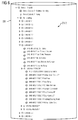
- Figure 6 illustrates a third exemplary database DB storing an exemplary data model DM3 comprising asset and performance data of the one or more buildings, wherein the data model is represented in one or more hierarchical tree-structures in accordance with disclosed embodiments of the present invention.
- the data model DM3 represents an exemplary "Arnold Building" having the root node "Arnold - Bldg M".
- To the root node "Arnold - Bldg M” are exemplary performance data "Arnold Outside Air Relative Humidity" and "Arnold Outside Air Temp" assigned.
- the "Arnold Building” comprises exemplary infrastructure for air handling which is represented in the data model DM3 with the node "Air Handling".
- the exemplary infrastructure for air handling comprises air handling units represented in the data model DM3 with the nodes "AHU-M-1-1" to "AHU-M-4-1".
- the node "AHU-M-3-2" illustrates further exemplary sub-structures.
- Rules are only executed on nodes where the node type matches the node types the rule is enabled for, e.g. a rule for the evaluation of AHU's is only executed on the nodes "AHU-M-" in the example according to figure 6 and not on VAV nodes "VAV Box".
- the respective nodes in the tree structure are being identified by metadata, in this example by the type of the node. Any metadata property of the assets can be used to control the scope of execution of the rules. While executing a rule on a relevant node the performance data directly related to this node is typically being used for the evaluation of the rule expression.
- Avg Zone Temp Lower Than RAT Average of zone air temperatures for zones served by the AHU is lower than AHU return air temperature
- the average zone air temperature is lower than the AHU return air temperature, it could indicate leakage of hot air into the return air duct or sensor measurement error. This could result in increased energy use especially during the cooling season.
- Figure 7 illustrates an exemplary schematic overview diagram of a script builder tool SB for generating executable code and/or executable modules for detecting faults and/or for providing optimization measures to enhance the performance of one or more buildings.
- the script builder tool SB comprises a database DB for storing a data model comprising asset and performance data of one or more buildings or of a campus.
- the data model is represented advantageously in one or more hierarchical tree-structures, wherein the nodes of the tree-structures represent asset data and the leaves of the tree-structures represent performance data of the one or more buildings.
- the performance data are represented in each case by data points comprising time series of measured or derived field values and meta information (meta data).
- Meta data for a data point of a device installed in a building can be for instance an identification (ID) for the data point, unit of measure, purpose (e.g. inlet temperature or return temperature).
- ID identification
- the data model comprises also weather data (e.g. current weather conditions (e.g. temperature, humidity in the local area of the one or more buildings), weather forecast information for the local area of the one or more buildings).
- weather data e.g. current weather conditions (e.g. temperature, humidity in the local area of the one or more buildings), weather forecast information for the local area of the one or more buildings.
- the weather data can be assigned to the nodes or to the leaves of the tree-structures according to the underlying modeling policy. If the modeling policy is mainly a top-down approach the weather data are advantageously assigned to the nodes. If the modeling policy is mainly a bottom-up approach the weather data are advantageously assigned to the leaves.
- the weather data can be provided by meteorological offices or weather stations.
- the data model comprises also energy data (e.g. energy prices, tariffs, shortage) provided by utilities or energy supplier.
- energy prices are assigned to nodes, especially to high level nodes, and the energy price will be inherited to nodes and leaves below this node.
- a high level node can be e.g. a customer who has a dedicated energy price model negotiated with a utility or an energy supplier.
- the dedicated energy price model is valid for all equipped infrastructure or devices in the customer's buildings.
- the script builder tool SB comprises a user interface UI (comprising input and displaying means) for configuring rules to analyze the asset and the performance data in respect to the building performance of the one or more buildings.
- the rules referring to data point mappings, parameters, asset data mappings, runtime settings, or schedules are configured by user input using logical operators and defined functions.
- the rules are processed and performed by an adequate rule engine RE.
- a code generator generates executable code modules (e.g. dll or exe files) at runtime based on the user configured rules.
- the rules are executed by a runtime system RS by traversing the tree-structures of the data model and collecting and processing the data affected by the respective rules.
- the user interface UI is a menu-driven user interface or in parts a menu-driven user interface.
- a script comprises 1 to n rules, for each script a executable code module (e.g. dll) is generated. Generating and executing an executable code module can be performed in one step.
- the executable code module (e.g. dll) is generated and executed at runtime by just-in-time (JIT) compilation.
- JIT just-in-time
- the generated code is executed directly by the runtime system RS.
- the runtime system RS acts as a host.
- Just-in-time (JIT) compilation offers a great flexibility for a user and a fast execution time for the generated object or machine code. If there are no changes in data points of the respective performance data generated object or machine code can be reused when a script is performed one more time.
- Scripts can be configured by parameters which will be accessed during runtime and by runtime settings.
- Parameters represent properties which are valid for a node (means an asset, e.g. system, sub-system, technical equipment) and the underlying nodes and leaves.
- Parameters assigned to a node (parent) will be inherited to underlying nodes and leaves.
- Runtime settings can be for instance tolerance ranges describing the e.g. the responsiveness of the FDD system.
- the rule engine RE, the code generator CG, and the runtime system RS are implemented in adequate software modules.
- the rule engine RE, the code generator CG, the runtime system RS, and the database DB are loadable and storable in a memory of the processing unit PU and the processing unit PU is configured to execute the software modules for the rule engine RE, the code generator CG, and the runtime system RS.
- the processing unit PU can be a personal computer or a workstation.
- the rule engine RE, the code generator CG, and the runtime system RS can be implemented in one module. It is also possible to implement the rule engine RE, the code generator CG, and the runtime system RS in each case in a dedicated module.
- the functions of the rule engine RE and the functions of code generator CG can also be implemented in one module.
- the processing unit PU is realized by a cloud computing infrastructure comprising mechanisms for data storing, data processing, and data connection, especially for connections from remote sources and/or to remote targets.
- the script builder tool SB further comprises an output unit OU (e.g. monitor or display of a tablet-computer) for outputting detected faults and/or providing optimization measures for the one or more buildings.
- the script builder tool SB further comprises an interface for delivering detected faults and/or optimization measures to a building automation system operating the one or more buildings.
- script builder tool SB further comprises an interface for delivering detected faults and/or optimization measures directly to the affected technical infrastructure of the one or more buildings.
- the delivering of detected faults and/or optimization measures can be realized in real-time or in an update batch (e.g. hourly or daily).
- the script builder tool SB can provide faults and/or optimization measures on demand, e.g. by a building owner who realizes that the energy bill for his building seems to be too high.
- the script builder tool SB can also operate in a batch mode e.g. on a daily, weekly, or monthly base. In the batch mode the script builder tool SB runs a batch with a set of rules regularly on defined point of times.
- the script builder tool SB can also be operated in an online mode. The online mode makes sense for monitoring or checking technical equipment which has to provide a high reliability.
- the script builder tool SB is able to aggregate the fault metric, number of faults, duration and cost to any node object from the system tree hierarchy (for example, a site would sum number of faults, duration of faults, and cost penalties at and below the site node).
- script builder tool SB allows an administrator to define custom data field that can be aggregated to any node object from the system tree hierarchy (for example a data field would be duration or cost).
- the script builder tool provides the ability to stack repeated faults to display only one line of those faults and provide indication of repeated faults (for example, if the same fault happens 1000 times, the system will stack the faults occurred and display one line for that fault).
- the script builder tool SB allows users (e.g. administrator) to create their own rules and activate them for specific pieces of equipment.
- users e.g. administrator
- an administrator is person who is responsible for configuring the setup of the script builder SB for a customer.
- Administrator can also be an advanced customer user who wishes to implement a FDD sytem (Fault Detection & Diagnosis) on their own.
- FDD sytem Fault Detection & Diagnosis
- the user interface UI of the script builder tool SB provides a configuration page and the detail page.
- the configuration page allows the user to define conditions that must be true in order for the rule exception to occur.
- the detail page allows the user to define all the associated information of the rule.
- the script builder tool SB provides a user interface UI for any users with no programming knowledge to create new rules utilizing common mathematical & statistical functions. For example this can be enabled by a drag-and-drop or by a drop-down programming environment that allows assembly of simple to complex expressions or rules by simply dragging available data and desired mathematical or logical functions together to produce any allowable combination.
- the script builder tool SB is a tool to support the human operator (Energy, System, Application Engineer) in his daily job without advanced knowledge of a specific programming language or by consulting a software programmer. This safes time, allows the user to focus on the evaluation logic and leads to individual scripts that can be leveraged by all enabled users and be applied to many different customers and their portfolio of buildings.
- Custom scripts/rules for individual customers can easily be created and assigned to the customers as everything is data/expression driven and stored in a global database.
- the script builder functionality itself can even be enabled for the customer himself.
- the cost involved in creating new rules for existing systems or new types of systems is reduced to a minimum.
- a service platform system e.g. Siemens Navigator platform
- the lead time to the customer is very short, the tasks can be distributed to many individuals. This lowers the cost, and increases the efficiency and performance towards the customer for providing custom scripts and rules.
- Figure 8 shows an exemplary flow diagram depicting a process for a computer-facilitated method for detecting faults, providing optimization measures, or both of the foregoing to enhance the performance of one or more buildings, including building automation equipment disposed in relation to the one or more buildings, the method comprising:
- Runtime settings for example can be user defined thresholds, upper limits, or lower limits regarding the time series in the data points.
- Runtime settings offer a user defined parameterization for running the method. For example only data between an upper and a lower limit could be used by the script builder. This allows e.g. a quick presentation of results.
- Meta data for a data point of a device installed in a building can be for instance an identification (identifier) for the data point, unit of measure, purpose (e.g. inlet temperature or return temperature).
- the generated optimization measures comprise fault periods, selected data points, output columns, or fault diagnosis. This gives a customer flexibility and possibility to choose the outputted data and/or the format of the outputted data he needs for his requirements.
- the optimization measures are inputted into a building management system for operating the one or more buildings.
- An operator can by using a management station (e.g. Desigo CC) of a building management system employ the recommended optimization measures to the respective buildings.
- a management station e.g. Desigo CC
- the building management system is directly coupled to a FDD system providing faults, optimization measures, or both of the foregoing for the respective buildings.
- the optimization measures are inputted directly into building automation equipment (infrastructure, devices) of the one or more buildings.
- the optimization measures can be employed in real-time in the building automation equipment.
- simple optimization measures can be employed in this approach, e.g. a recommended switch on or switch off of a device.
- FIG. 1 A block diagram illustrating an exemplary computing environment in accordance with the invention.
- FIG. 1 A block diagram illustrating an exemplary computing environment in accordance with the invention.
- FIG. 1 A block diagram illustrating an exemplary computing environment in accordance with the invention.
- Computer readable media can be any available media that can be accessed by a computer.
- Computer readable media can exemplary comprise computer storage media and communication media.
- Computer storage media comprises volatile and non volatile as well as removable and non-removable media implemented in any method or technology for storage of information such as computer readable instructions, data structures, program modules or other data.
- Computer storage media for example comprises RAM, ROM, EEPROM, flash memory or other memory technology, CDROM, digital versatile disks (DVD) or other optical disk storage, or any other medium which can be used to store the desired information and which can be accessed by a computer.
- Figure 9 illustrates an exemplary user interface for an exemplary script builder.
- the exemplary user interface comprises a script level SL and a rule level RL.
- the script level SL provides general configuration options which can be used by all rules and administrative functions to manage scripts.
- the rule level RL a user configures a set of rules for the script including their evaluation expression, select data points to be shown together with the fault result, related runtime settings.
- Figure 10 shows an exemplary list LRS of runtime settings for configuring a script builder.
- Runtime Settings control the rule execution.
- Values (Settings) can be set by the end user prior to running a script.
- Figure 11 illustrates an exemplary user interface UI for defining calculated fields in data points.
- the user interface (UI) of the script builder allows to define calculated fields accessible in data points and tagging and set publish options for the result grid and/or the result tree.
- Figure 12 illustrates a further exemplary user interface UI for an exemplary script builder.
- the user interface UI shown in figure 12 allows a user to select/map data point types and node/asset properties relevant for the script and define required virtual (calculated/derived) data points.
- Figure 13 illustrates an exemplary user interface UI for tagging scripts or rules.
- the user can select applicable node types for the script/rule and define further filters based on node/asset properties for the complete script or individual rules.
- Figure 14 illustrates an exemplary user interface UI for schedule settings.
- the user can set the schedules for the script or rules for certain nodes respective assets. Only faults detected within these schedules will be recognized as fault and shown to the user.
- the inheritance principle is applied for schedules, which means that they are taken for lower nodes as well when being defined on a higher node in the asset tree.
- Figure 15 illustrates an exemplary user interface UI for fault diagnosis.
- the system for detecting faults and/or for providing optimization measures to enhance the performance of one or more buildings can define probable causes and suggested (mitigation) actions for respective rules. This helps the user to understand what to do if a certain fault has occurred.
- Figure 16 illustrates an exemplary user interface UI for an expression editor for defining rules or part of rules.
- a user can define the evaluation expression (logic) of the rule supported by selection lists for available custom functions, defined (virtual) data points and node/asset properties from the script level as well as runtime settings, calculated fields and global parameters.
- An easy to understand "function-in-function-in-function" concept supports the user in putting the logic together.
- Figure 17 shows an exemplary user interface UI for presenting results of script execution.
- the user interface UI according to figure 17 shows an exemplary dashboard for presenting the results, e.g. detected faults, defects and/or suggested optimization measures.
- the window on the left-hand side of the exemplary dashboard shows a hierarchy of a result tree.
- the tree hierarchy is be able to display numerical data next to the tree node name and the users are able to select what data parameters they would like to see (Example: Duration or Cost or Number of Faults or Trends).
- the user is able to select a custom data field to be aggregated and displayed in the tree to the right of the Node Names.
- a database for storing a data model comprising asset and performance data of the one or more buildings, wherein the data model is represented in one or more hierarchical tree-structures, wherein the nodes of the tree-structures represent asset data and the leaves of the tree-structures represent performance data of the one or more buildings, wherein the performance data are represented in each case by data points, wherein the data points comprising time series of measured or derived field values and meta information.
- a user interface e.g.
- a menu-driven user interface for configuring the rules for analyzing the asset and the performance data in respect to the building performance of the one or more buildings, wherein the rules referring to data point mappings, parameters, asset data mappings, runtime settings, or schedules are configured by user input using logical operators and defined functions.
- Executable code modules e.g. dll-files
- An adequate output unit is provided for outputting detected faults and/or providing optimization measures for the one or more buildings.
Landscapes
- Engineering & Computer Science (AREA)
- Physics & Mathematics (AREA)
- General Physics & Mathematics (AREA)
- Theoretical Computer Science (AREA)
- Databases & Information Systems (AREA)
- General Engineering & Computer Science (AREA)
- Automation & Control Theory (AREA)
- Data Mining & Analysis (AREA)
- Software Systems (AREA)
- Medical Informatics (AREA)
- Evolutionary Computation (AREA)
- Computer Vision & Pattern Recognition (AREA)
- Health & Medical Sciences (AREA)
- Artificial Intelligence (AREA)
- Manufacturing & Machinery (AREA)
- Quality & Reliability (AREA)
- Management, Administration, Business Operations System, And Electronic Commerce (AREA)
Abstract
Description
- The present invention relates generally to the technical field of building management systems or building automation systems. In particular the present invention relates to systems and methods for detecting faults and/or for providing optimization measures to enhance the performance of one or more buildings, especially the building automation equipment of the one or more buildings.
- The management of energy by a building automation system (BAS) is the combination of actions taken to maximize energy usage efficiency and optimize energy supply to lower energy costs without sacrificing occupant needs and comfort. To achieve these building performance goals, actions may include reducing end use of energy consuming equipment, increasing efficiency of equipment, eliminating wasted energy, finding less costly alternative energy sources, minimizing procurement costs, or detecting faults in building equipment.
- Equipment faults in buildings cause undesirable effects such as e.g. increasing the energy consumption or decreasing the lifespan of equipment. There are known various methods of fault detection, including statistical analysis methods and methods for statistical process control. These methods are often cumbersome to operate or use in or with a BAS, or they require programming experience.
- Therefore there is a need for building owners or building operators for easy to use methods or systems for detecting faults and/or for providing optimization measures to enhance the performance of buildings.
- The object of the invention is to provide methods and systems for fault detection and diagnosis which are easy to operate by building operators.
- This object will be achieved by a computer-facilitated method for detecting faults, providing optimization measures, or both of the foregoing to enhance the performance of one or more buildings, including building automation equipment disposed in relation to the one or more buildings, the method comprising:
- providing a database (DB) storing a data model comprising asset data and performance data of the one or more buildings, wherein the data model is represented in one or more hierarchical tree-structures each having a plurality of nodes and a plurality of leaves,
- wherein the nodes of the tree-structures represent asset data and the leaves of the tree-structures represent performance data of the one or more buildings,
- wherein the performance data are represented in each case by data points, wherein the data points comprise time series of measured or derived field values and meta information;
- providing a user interface for configuring rules for analyzing the asset data and the performance data in respect to the building performance of the one or more buildings,
- wherein the rules refer to data point mappings, parameters, asset data mappings, runtime settings, or schedules and are configured by user input using logical operators and defined functions;
- generating executable code modules at runtime based on the user configured rules by a processing unit, wherein the rules are executed by a runtime system traversing the tree-structures of the data model; and
- outputting detected faults and/or optimization measures regarding the one or more buildings on an output device.
- The object will be further achieved by a system for detecting faults, providing optimization measures, or both of the foregoing to enhance the performance of one or more buildings, including building automation equipment disposed in relation to the one or more buildings, the system comprising:
- a database storing a data model comprising asset data and performance data of the one or more buildings, wherein the data model is represented in one or more hierarchical tree-structures each having a plurality of nodes and a plurality of leaves,
- wherein the nodes of the tree-structures represent asset data and the leaves of the tree-structures represent performance data of the one or more buildings,
- wherein the performance data are represented in each case by data points, wherein the data points comprise time series of measured or derived field values and meta information;
- a user interface for configuring rules for analyzing the asset data and the performance data in respect to the building performance of the one or more buildings,
- wherein the rules refer to data point mappings, parameters, asset data mappings, runtime settings, or schedules and are configured by user input using logical operators and defined functions;
- a processing unit for generating executable code modules at runtime based on the user configured rules, wherein the rules are executed by a runtime system traversing the tree-structures of the data model; and
- an output unit for outputting detected faults, providing optimization measures, or both of the foregoing for the one or more buildings.
- The object will be further achieved by a script builder tool for generating executable code modules for detecting faults, providing optimization measures, or both of the foregoing to enhance the performance of one or more buildings, the script builder tool comprising:
- a database storing a data model comprising asset data and performance data of one or more buildings, wherein the data model is represented in one or more hierarchical tree-structures each having a plurality of nodes and a plurality of leaves, wherein the nodes of the tree-structures represent asset data and the leaves of the tree-structures represent performance data of the one or more buildings, wherein the performance data are represented in each case by data points, wherein the data points comprise time series of measured or derived field values and meta information;
- a user interface for configuring rules for analyzing the asset data and the performance data in respect to the building performance of the one or more buildings, wherein the rules refer to data point mappings, parameters, asset data mappings, runtime settings, or schedules and are configured by user input using logical operators and defined functions;
- a processing unit for generating executable code modules at runtime based on the user configured rules, wherein the rules are executed by a runtime system traversing the tree-structures of the data model.
- The above-mentioned and other concepts of the present invention will now be addressed with reference to the drawings of the preferred embodiments of the present invention. The shown embodiments are intended to illustrate, but not to limit the invention. The drawings contain the following figures, in which like numbers refer to like parts throughout the description and drawings and wherein:
- FIG 1
- illustrates a first exemplary schematic overview diagram of a system for detecting faults and/or providing optimization measures to enhance the performance of one or more buildings that depicts various aspects and embodiments of the present invention;
- FIG 2
- illustrates a second exemplary schematic overview diagram of a system for detecting faults and/or providing optimization measures to enhance the performance of one or more buildings that depicts various aspects and embodiments of the present invention, including the integration of the system to a building management system (BMS);
- FIG 3
- illustrates a third exemplary schematic overview diagram of a system for detecting faults and/or providing optimization measures to enhance the performance of one or more buildings that depicts various aspects and embodiments of the present invention, including the integration of the processing unit and the database in a cloud;
- FIG 4
- illustrates a first exemplary database storing a data model comprising asset data and performance data of the one or more buildings, wherein the data model is represented in one or more hierarchical tree-structures in accordance with disclosed embodiments of the present invention;
- FIG 5
- illustrates a second exemplary database storing a data model comprising asset data and performance data of the one or more buildings, wherein the data model is represented in one or more hierarchical tree-structures in accordance with disclosed embodiments of the present invention;
- FIG 6
- illustrates a third exemplary database storing a data model comprising asset data and performance data of the one or more buildings, wherein the data model is represented in one or more hierarchical tree-structures in accordance with disclosed embodiments of the present invention;
- FIG 7
- illustrates an exemplary schematic overview diagram of a script builder tool for generating executable code and/or modules for detecting faults and/or for providing optimization measures to enhance the performance of one or more buildings;
- FIG 8
- shows an exemplary flow diagram depicting a process for detecting faults and/or for providing optimization measures to enhance the performance of one or more buildings in accordance with disclosed embodiments of the present invention;
- FIG 9
- illustrates an exemplary user interface for an exemplary script builder tool;
- FIG 10
- shows an exemplary list of runtime settings for configuring a script builder tool;
- FIG 11
- illustrates an exemplary user interface of a script builder tool for defining calculated fields in data points;
- FIG 12
- illustrates a further exemplary user interface for an exemplary script builder tool;
- FIG 13
- illustrates an exemplary user interface of a script builder tool for tagging scripts or rules;
- FIG 14
- illustrates an exemplary user interface of a script builder tool for schedule settings;
- FIG 15
- illustrates an exemplary user interface of a script builder tool for fault diagnosis;
- FIG 16
- illustrates an exemplary user interface for an expression editor for defining rules or part of rules; and
- FIG 17
- shows an exemplary user interface of a system for presenting results in accordance with disclosed embodiments.
- "Smart buildings" generate a lot of traffic and an increasingly large amount of data. Therefore, there is a focus on the performance and optimization of building systems, respectively sub-systems (e.g. air distribution, cooling, heating, lighting) and individual technical infrastructure or equipments within these systems, like air handling units, chillers, boilers, etc. This requires the analysis of huge amounts of time series data (e.g. performance data) and their timely correlation by sophisticated rules to find inefficiencies in operation, deviation from control strategy, or negative impact on the building comfort, for example. System engineers or energy engineers need to analyze the data frequently in order to measure, find faults, or give advice to improve the performance of equipments, sub-systems, systems, or buildings.
- A user (e.g. building owner, building operator) therefore is to be expected to know about the individual setup of equipments in terms of its specific type and associated parameters, the available data points, operational schedules, etc. Additionally the user needs to align or normalize the data point time series regarding the required analysis granularity, as the raw data granularity can vary from data point to data point, e.g. time series data can be available as 1-, 5- or 15-minute samples, and the analysis should be advantageously performed in 15-minute intervals, which would require the compression of the higher granular time series to 15-minute values based on a certain compress function, like Sum/Average/Min/Max. The user needs also to ensure that the units of measure of the data series fit to each other across the analysis scenario to perform correct calculations.
- Once all the preparatory tasks have been performed and the analytics context has been completely defined and data has been gathered for the period to be analyzed, the actual analysis can start by defining the logic the user wants to apply to the data to detect the anomalies or patterns he is looking for. This logic can be called a rule, and a collection of several rules e.g. for a certain type of system or equipment can be put together in a script. The execution of rules can be limited to certain types of assets (buildings, systems, equipments etc.), or the execution of rules can be designed to a certain asset. To support the mitigation process of faults being detected by technicians or facility managers, the script builder tool advantageously allows the assignment of probable causes (means defects or faults) and potential actions (optimization or improvement measures) that could be taken on a per rule basis.
- Advantageously the scripts or rules can be executed even by occasional users for the whole portfolio of buildings, systems, sub-systems, or equipments of a customer at once, and they can be applied to different customers without having to be recreated or re-generated. The results can be presented in various forms like a navigation tree showing aggregated results, an overview grid and/or graphically. To support this goal the script builder tool provides functionality to configure the published data on a per script or rule basis comprising the definition of aggregated information like the number of fault occurrences and durations and the ability to assign the accompanying trend data series which could help the user to better understand the actual conditions when the fault occurred.
- Today the execution of such tasks is done one-by-one by a human operator by leveraging spreadsheet tools like MS Excel or scripting solutions with proprietary scripting languages and visually inspecting trend data charts to detect anomalies and patterns. Alternatively an expert can write and test the scripts or rules as he knows the necessary commands and understands the context of the queried data to choose the necessary operands in order to get useful results back or tasks to be executed. If a human operator (e.g. Facility Manager) wants to run specific queries or execute jobs that are relevant for him e.g. to improve the performance of his building or compare buildings with each other, he has to become an expert or ask someone to do the programming job for him.
Figure 1 illustrates a first exemplary schematic overview diagram of a system S1, especially a FDD-system (Fault Detection and Diagnosis System) for detecting faults and/or providing optimization measures to enhance the performance of one or more buildings B. The exemplary system S1 comprises a database DB storing a data model comprising asset AD and performance data PD of the one or more buildings B, wherein the data model is represented in one or more hierarchical tree-structures. The exemplary system S1 further comprises a user interface UI (advantageously a menu-driven user interface UI) for configuring rules for analyzing the asset AD and the performance data PD in respect to the building performance of the one or more buildings B. The rules referring to data point mappings, parameters, asset data mappings, runtime settings, or schedules which are configured by user input using logical operators and defined functions. The rules are created and configured using an Input Unit IU comprising keyboard, mouse, etc., and the user interface UI. Advantageously the user interface UI provides input fields IPF1 - IPF3 for creating and configuring the rules by using logical operators (e.g. "AND", "for", "EQUAL", "GREATER", "SMALLER") and defined functions, e.g. predefined macros or subroutines. - The exemplary system S1 furthermore comprises a processing unit PU for generating executable code modules (e.g. dll, "Dynamic Link Libraries") at runtime based on the user configured rules. The rules are executed by a runtime system traversing the tree-structures of the data model. In the illustration according to
figure 1 the module code generator CG comprises a rule engine for checking the syntax of the rules and for assembling the rules to an executable script. The module code generator CG further comprises a module for code generation to automatically generate executable code modules (e.g. dll files or exe files) to run the script on the respective runtime system RS. The runtime system RS is configured to run the generated code modules (e.g. dll files or exe files) on the processing unit PU. The processing unit PU can be for instance a Personal Computer (PC) or a Workstation. The processing unit PU is equipped and configured with appropriate hardware and software components. The PU can also be implemented in a cloud computing environment. - The database DB which stores the data model comprising asset AD and performance data PD of the one or more buildings B can be integrated in a memory (e.g. drive or flash memory) of the processing unit PU. The database DB could also be stored in an in an In-Memory-Database of the processing unit PU. Storing the database DB an In-Memory-Database of the processing unit PU is especially advantageous for applications which require very high response times for providing faults to the user.
- In the exemplary embodiment according to
figure 1 the processing unit PU has access to the database DB via an adequate communication interface (e.g. a wireless or radio connection). The database DB could also be implemented in a cloud. This allows the sharing of the resource database DB to more than one processing units PU. A provider of the resource database DB (including the respective data model comprising asset AD data and performance PD data of one or more buildings B) could provide the content of the database DB for customer as software-as-a-service. - Advantageously the content of the database DB, means the data model comprising asset AD and performance data PD of the one or more buildings B is arranged in one or more tree-structures each having a plurality of nodes and a plurality of leaves. The nodes of the tree-structures represent asset data AD and the leaves of the tree-structures represent performance data PD of the one or more buildings B. In the one or more tree-structures the performance data PD are represented in each case by data points, the data points comprising time series of measured or derived field values and meta information of the technical equipment (e.g. HVAC equipment) of the one or more buildings B.
- The asset data AD of the one or more buildings B comprise information regarding the technical infrastructure or technical equipment for climate control (HVAC), and/or access control, and/or energy supply and control, and/or security and/or fire safety of the one or more buildings B. The asset data AD of the one or more buildings B include but are not limited to one or more of the following: passive data (e.g. types and quantities of employed systems, subsystems, components equipped in the one or more buildings B), setting data, weather data, energy tariff rates (e.g. energy prices) or emission factors (e.g. CO2). Since asset data AD of a building B do not change very frequently, the asset data AD can be submitted to the database DB for instance by an update batch (e.g. daily, weekly, monthly) or if the building B is equipped with a piece of newly installed or changed infrastructure device.
- The performance data PD of the one or more buildings B comprise: building control system data, and/or electricity metering data, and/or heat metering data, and/or water metering data, and/or temperature data, and/or humidity data, and/or pressure data, and/or events, and/or alarms. This listing is not limited. The performance data PD regarding the technical equipment have to be monitored permanently to derive reliable conclusions regarding the detection faults or defects of the technical equipment in a building B. Advantageously the performance data PD are submitted to the database DB in a resolution in between 1 and 60 minutes, in particular in a resolution in between 1 and 15 minutes. This enables a fast response to time critical requests or time critical applications in providing detected faults F and/or optimization measures OM for a customer.
- The asset AD and the performance data PD of the one or more buildings B can be submitted to the database advantageously by a wireless communication connection (e.g. adequate radio connection). Adequate wired communication connections can also be used.
- The exemplary system S1 further comprises an output unit OU for outputting detected faults F and/or providing optimization measures OM regarding the one or more buildings B. The output unit OU could be a display of a computer monitor, a display of a tablet computer, a display of a handheld device (e.g. Smartphone), or the display of a monitor station of a building automation system or building management system (e.g. Desigo CC).
-
Figure 2 illustrates a second exemplary schematic overview diagram of a system S2 for detecting faults F and/or providing optimization measures OM to enhance the performance of one or more buildings B. Compared to the system S1 illustrated infigure 1 , the system S2 illustrated infigure 2 is additionally connected or integrated to a building management system BMS. A building management system BMS controls and/or monitors the technical equipment (e.g. mechanical or electrical devices) and sub-systems (e.g. power systems, security systems, heating systems, ventilation systems, or evacuation systems) of the one or more buildings B. Advantageously the detected faults F and/or the optimization measures OM are inputted directly (online) into the building management system BMS for operating the one or more buildings B. The detected faults F and/or the optimization measures OM can also be reported offline (e.g. as a daily update batch) into the building management system BMS. Based on the detected faults F and/or the optimization measures OM the building management system BMS can derived or create improvement data ID in an adequate granularity for the respective technical infrastructure affected by the detected faults F or optimization measures OM. - In a further advantageous embodiment the optimization measures OM are inputted directly to the respective affected technical automation equipment of the one or more buildings B. This can be realized via suitable communication means (e.g. Internet or radio communication) in an online (real time) mode or in an offline (batch mode). To engage directly online or in real time to recognized affected or defect technical automation equipment of the one or more buildings B is especially advantageous if the derived optimization measures OM are easily to implement, e.g. switching on or off of a device or sub-system in the one or more buildings B.
-
Figure 3 illustrates a third exemplary schematic overview diagram of a system S3 for detecting faults and/or providing optimization measures to enhance the performance of one or more buildings B that depicts various aspects and embodiments of the present invention, especially the integration of the processing unit PU and the database DB in a cloud C. Advantageously the infrastructure of cloud C is implemented Internet-based and the database DB is realized as remotely accessible database server or file server. Advantageously the processing unit PU is realized as a server computer offering diagnosis services to the respective clients (e.g. building operators, building owners, facility manager). - The processing unit PU and the database DB of the FDD system S3 can be integrated or be part of a service platform system which is realized as a cloud based platform, wherein the infrastructure and/or the platform and/or the software programs (or parts of the infrastructure or of the platform or of the software) are provided by a cloud service provider.
- Advantageously the database DB comprises not only asset data AD and performance data PD of the one or more buildings B, but also energy prices EP provided by a utility or an energy supplier ES. Advantageously the database DB comprises also weather data, weather forecast data, or data regarding consumable resources (e.g. water, fuel) utilized in the one or more buildings B. The weather data can be provided by a weather data or weather forecast provider. This can be a private and/or a public provider.
-
Figure 4 illustrates a first exemplary database DB storing a first exemplary data model DM1 comprising asset and performance data of the one or more buildings. The data model DM1 is represented in one or more hierarchical tree-structures, wherein the nodes AHU, AD1, AD2 of the tree-structures represent asset data and the leaves of the tree-structures represent performance data of the one or more buildings. The performance data PD1 - PD6 of the technical equipment of the one or more buildings are represented in each case by data points, wherein the data points comprising time series of measured or derived field values and meta information of the technical equipment. The exemplary data model DM1 shows a tree-structure for an exemplary schematic air handling unit AHU equipped in a building B. The illustrated exemplary schematic air handling unit AHU comprises two exemplary subsystems. For instance a heating sub-system (e.g. a boiler) and a cooling sub-system (e.g. a chiller). The heating sub-system and the cooling sub-system are represented in the data model DM1 as asset data AD1 respectively AD2. For example, asset data AD1 does represent the heating sub-system, and asset data AD2 the cooling sub-system of the air handling unit AHU. To the asset data AD1 representing the heating sub-system the performance data PD1 - PD3 are assigned. The performance data PD1 - PD3 represent exemplary data points of the heating sub-system of the air handling unit AHU. The data points comprise time series of measured or derived field values and meta information of the exemplary heating sub-system of the air handling unit AHU. The performance data PD1 - PD3 of the heating sub-system AD1 can be e.g. air temperature, air velocity, and air humidity. The performance data PD4 - PD6 assigned to asset data AD2 can be e.g. the corresponding measures regarding air temperature, air velocity, and air humidity of the cooling sub-system AD2 of the air handling unit AHU. - According to the infrastructure equipped in the one or more buildings B the exemplary data model DM1 can comprise more than one tree-structures. The inventive script builder tool traverses or crawls through the data model DM1 to collect the required asset data AD1, AD2 and performance data PD1 - PD6 for the respective rules built by a user by using an adequate user interface.
- The leaves PD1 - PD6 in a tree-structure of the data model DM1 can also comprise virtual data points. Virtual data points can be e.g. a derived time series. An example of a virtual data point is e.g. the difference of the values of two data points, e.g. the difference of inlet temperature and return temperature. By using virtual data points the clarity of rules can be increased.
-
Figure 5 illustrates a second exemplary database DB storing a second exemplary data model DM2 comprising asset and performance data of an exemplary "Stephen Test" site or campus. "Stephen Test" site represents the root of the exemplary data model DM2. The exemplary data model DM2 shows in a coarse grain a hierarchical tree-structure with asset data of the "Stephen Test" site or campus. The "Stephen Test" site or campus comprises a "Building Pool 1" which has a "Site 1". The "Site 1" is equipped with "Equipment 1". The performance data assigned to "Equipment 1" are not shown infigure 5 . - The second exemplary database DB could comprise more than one tree-structures, depending on the quantity and size of the technical infrastructure of the one or more buildings mapped data model DM2.
- In the data model DM2 weather data (current, forecast) can be assigned to the nodes as asset data or to the leaves of the tree-structures as performance data, depending on the modeling approach or strategy.
- Advantageously energy data (energy price EP, tariff, shortage) are assigned in the data model DM2 to the nodes as asset data. The data assigned to parent nodes are inherited to the child nodes and so on till to the leaves of the tree-structures.
- Advantageously the tree structure of the data model DM2 comprises the following levels: Customer, Building Pool, Site, System and Equipment. By implementing this as a standard scenario there is a great chance of success for implementation and execution as the results of customer setups will be more predictable.
- Advantageously the data model DM2 allows the user the ability to setup up unlimited different levels of a hierarchical structure (Example: Customer > Region > Building > Floor > Zone > ACME Enterprise, ACME Manufacturing, ACME Region, ACME State, ACME Campus, ACME Building, System, Floor, Zone, Point).
- Advantageously the tree hierarchy is be able to display numerical data next to the tree node name and the user shall be able to select what data parameters they would like to see (Example: Duration or Cost or Number of Faults or Trends).
- Advantageously the user is able to select a custom data field to be aggregated and displayed in the tree to the right of the Node Names.
-
Figure 6 illustrates a third exemplary database DB storing an exemplary data model DM3 comprising asset and performance data of the one or more buildings, wherein the data model is represented in one or more hierarchical tree-structures in accordance with disclosed embodiments of the present invention. The data model DM3 represents an exemplary "Arnold Building" having the root node "Arnold - Bldg M". To the root node "Arnold - Bldg M" are exemplary performance data "Arnold Outside Air Relative Humidity" and "Arnold Outside Air Temp" assigned. The "Arnold Building" comprises exemplary infrastructure for air handling which is represented in the data model DM3 with the node "Air Handling". The exemplary infrastructure for air handling comprises air handling units represented in the data model DM3 with the nodes "AHU-M-1-1" to "AHU-M-4-1". Infigure 6 the node "AHU-M-3-2" illustrates further exemplary sub-structures. - Rules are only executed on nodes where the node type matches the node types the rule is enabled for, e.g. a rule for the evaluation of AHU's is only executed on the nodes "AHU-M-..." in the example according to
figure 6 and not on VAV nodes "VAV Box...". The respective nodes in the tree structure are being identified by metadata, in this example by the type of the node. Any metadata property of the assets can be used to control the scope of execution of the rules. While executing a rule on a relevant node the performance data directly related to this node is typically being used for the evaluation of the rule expression. - Common performance data points like the "Outside Air Relative Humidity" and "Outside Air Temperature", which are for example only defined on the building level, can also be referenced by the rules executed on lower level nodes of the tree hierarchy. This is supported by the inheritance principles/functionality provided by the runtime system. Another important functionality of the runtime system is the aggregation. Aggregation allows a rule to reference performance data of lower level nodes e.g. VAV's for the execution on a higher level node e.g. AHU. Several aggregation functions are supported e.g. Average/Sum/Min/Max.
- In the following an example for a rule regarding an exemplary air handling unit and possible Impact of detected faults is shown.
- Avg Zone Temp Lower Than RAT Average of zone air temperatures for zones served by the AHU is lower than AHU return air temperature
-
 And(
 GT(SF_STATUS,0),
 LT(Average(Children(SPACE_TEMP)),Subtract(RAT,
 EPSILON_AIR_TEMP))
 );
- The script builder tool SB provides general configuration options on script level which can be used by all rules including administrative functions to manage scripts.
- The script builder tool SB provides configuration of rules for the script including their evaluation expression, select data points to be shown together with the fault result, related runtime settings.
- The script builder tool SB allows a user to define runtime settings (input values) to control the rule execution. Values can be set by the end user prior to running a script.
- The script builder tool SB allows to define calculated fields accessible in data points and tagging and set publish options for the result grid and/or the result tree
- The script builder tool SB allows to select or to map data point types and node/asset properties relevant for the script and to define required virtual (calculated/derived) data points.
- The script builder tool SB allows to select applicable node types for the script/rules and to define further filters based on node/asset properties for the complete script or individual rules.
- The script builder tool SB allows to set the schedules for the script/rules for certain nodes/assets. Only faults detected within these schedules will be recognized as fault and shown to the user. The inheritance principle is applied for schedules, which means that they are taken for lower nodes as well when being defined on a higher node in the asset tree.
- The script builder tool SB provides probable causes and suggestes (mitigation) actions for rules. This helps the user to understand what to do if a certain fault has occurred.
- The script builder tool SB allows to define the evaluation expression (logic) of the rule supported by selection lists for available custom functions, defined (virtual) data points and node/asset properties from the script level as well as runtime settings, calculated fields and global parameters.
- The script builder tool SB provides an easy to understand function-in-function-in-function concept supporting the user in putting the logic together.
- For different assets the same rules can be used if the assets have the same data points. E.g. two air handling units having the same data points can be analyzed by the same rule set. This provides a high reusability of rules or scripts.
- (S1) providing a database storing a data model comprising asset data and performance data of the one or more buildings, wherein the data model is represented in one or more hierarchical tree-structures each having a plurality of nodes and a plurality of leaves, wherein the nodes of the tree-structures represent asset data and the leaves of the tree-structures represent performance data of the one or more buildings, wherein the performance data are represented in each case by data points, wherein the data points comprise time series of measured or derived field values and meta information;
- (S2) providing a user interface for configuring rules for analyzing the asset data and the performance data in respect to the building performance of the one or more buildings, wherein the rules refer to data point mappings, parameters, asset data mappings, runtime settings, or schedules and are configured by user input using logical operators and defined functions;
- (S3) generating executable code modules at runtime based on the user configured rules by a processing unit, wherein the rules are executed by a runtime system traversing the tree-structures of the data model; and
- (S4) outputting detected faults, optimization measures, or both of the foregoing regarding the one or more buildings on an output device.
- S1 - S3
- FDD System
- C
- Cloud
- SB
- Script Builder
- IU
- Input Unit
- UI
- User Interface
- IPF1 - IPF3
- Input Field
- OU
- Output Unit
- PU
- Processing Unit
- CG
- Code Generator
- RS
- Runtime System
- RE
- Rule Engine
- B
- Building
- AD, AD1, AD2
- Asset Data
- PD, PD1 - PD6
- Performance Data
- ES
- Energy Supplier
- EP
- Energy Price
- DB
- Database
- DM1 - DM3
- Data Model
- BMS
- Building Management System
- F
- Faults
- OM
- Optimization Measures
- ID
- Improvement Data
- AHU
- Air Handling Unit
- SL
- Script Level
- RL
- Rule Level
- LRS
- List of Runtime Settings
Claims (15)
- A computer-facilitated method for detecting faults (F), providing optimization measures (OM), or both of the foregoing to enhance the performance of one or more buildings (B), including building automation equipment disposed in relation to the one or more buildings (B), the method comprising:(S1) providing a database (DB) storing a data model (DM1 - DM3) comprising asset data (AD, AD1 - AD2) and performance data of the one or more buildings (B), wherein the data model (DM1 - DM3) is represented in one or more hierarchical tree-structures each having a plurality of nodes and a plurality of leaves,
wherein the nodes of the tree-structures represent asset data (AD, AD1 - AD2) and the leaves of the tree-structures represent performance data (PD, PD1 - PD6) of the one or more buildings (B),
wherein the performance data (PD, PD1 - PD6) are represented in each case by data points, wherein the data points comprise time series of measured or derived field values and meta information;(S2) providing a user interface (UI) for configuring rules for analyzing the asset data (AD, AD1 - AD2) and the performance data (PD, PD1 - PD6) in respect to the building performance of the one or more buildings (B),
wherein the rules refer to data point mappings, parameters, asset data mappings, runtime settings, or schedules and are configured by user input using logical operators and defined functions;(S3) generating executable code modules at runtime based on the user configured rules by a processing unit (PU), wherein the rules are executed by a runtime system (RS) traversing the tree-structures of the data model (DM1 - DM3); and(S4) outputting detected faults (F), optimization measures (OM), or both of the foregoing regarding the one or more buildings (B) on an output device (OU). - The method of claim 1, wherein the rule execution is performed according to runtime settings.
- The method according to one of the preceding claims, wherein traversing the tree-structures of the data model (DM1 - DM3) is based according to the meta information of the data points.
- The method according to one of the preceding claims, wherein the optimization measures (OM) comprise fault periods, selected data points, output columns, or fault diagnosis.
- The method according to one of the preceding claims, wherein the optimization measures (OM) are inputted into a building management system (BMS) for operating the one or more buildings (B).
- The method according to one of the preceding claims, wherein the optimization measures (OM) are inputted into building automation equipment of the one or more buildings (B).
- A computer-readable medium containing a set of instructions that causes a computer to perform a method according to one of the claims 1 to 6.
- A computer program product loadable into the memory of a digital computer comprising software code portions for performing a method according to one of the claims 1 to 6 when said product is run on a computer.
- A system (S1 - S3) for detecting faults (F), providing optimization measures (OM), or both of the foregoing to enhance the performance of one or more buildings (B), including building automation equipment disposed in relation to the one or more buildings (B), the system (S1 - S3) comprising:a database (DB) storing a data model (DM1 - DM3) comprising asset data (AD, AD1 - AD2) and performance data (PD, PD1 - PD6) of the one or more buildings (B), wherein the data model (DM1 - DM3) is represented in one or more hierarchical tree-structures each having a plurality of nodes and a plurality of leaves,wherein the nodes of the tree-structures represent asset data (AD, AD1 - AD2) and the leaves of the tree-structures represent performance data (PD, PD1 - PD6) of the one or more buildings (B),wherein the performance data (PD, PD1 - PD6) are represented in each case by data points, wherein the data points comprise time series of measured or derived field values and meta information;a user interface (UI) for configuring rules for analyzing the asset data (AD, AD1 - AD2) and the performance data (PD, PD1 - PD6) in respect to the building performance of the one or more buildings (B),wherein the rules refer to data point mappings, parameters, asset data mappings, runtime settings, or schedules and are configured by user input using logical operators and defined functions;a processing unit (PU) for generating executable code modules (dll) at runtime based on the user configured rules, wherein the rules are executed by a runtime system (RS) traversing the tree-structures of the data model (DM1 - DM3); andan output unit (OU) for outputting detected faults (F) and/or providing optimization measures (OM) for the one or more buildings (B).
- The system (S1 - S3) according to claim 9, wherein the output unit (OU) is a display of a computer monitor, a display of a handheld device, or the display of a monitor station of a building automation system (BMS).
- The system (S1 - S3) according to one of the claims 9 to 10, further comprising an interface to a building automation system (BMS) operating the one or more buildings (B).
- The system (S1 - S3) according to one of the claims 9 to 11, further comprising an interface to building automation equipment of the one or more buildings (B).
- A script builder tool (SB) for generating executable code modules for detecting faults (F), providing optimization measures (OM), or both of the foregoing to enhance the performance of one or more buildings (B), the script builder tool (SB) comprising:a database (DB) storing a data model (DM1 - DM3) comprising asset data (AD, AD1 - AD2) and performance data (PD, PD1 - PD6) of one or more buildings (B), wherein the data model (DM1 - DM3) is represented in one or more hierarchical tree-structures each having a plurality of nodes and a plurality of leaves, wherein the nodes of the tree-structures represent asset data (AD, AD1 - AD2) and the leaves of the tree-structures represent performance data (PD, PD1 - PD6) of the one or more buildings (B), wherein the performance data (PD, PD1 - PD6) are represented in each case by data points, wherein the data points comprise time series of measured or derived field values and meta information;a user interface (UI) for configuring rules for analyzing the asset data (AD, AD1 - AD2) and the performance data (PD1 - PD6) in respect to the building performance of the one or more buildings (B), wherein the rules refer to data point mappings, parameters, asset data mappings, runtime settings, or schedules and are configured by user input using logical operators and defined functions;a processing unit (PU) for generating executable code modules at runtime based on the user configured rules, wherein the rules are executed by a runtime system (RS) traversing the tree-structures of the data model (DM1 - DM3).
- The script-builder according to claim 13, further comprising an output unit (OU) for outputting detected faults (F), providing optimization measures (OM), or both of the foregoing for the one or more buildings (B), including building automation equipment disposed in relation to the one or more buildings (B).
- The script-builder according to claim 13 or 14, further comprising an interface for delivering detected faults (F), optimization measures (OM), or both of the foregoing to a building automation system (BMS) operating the one or more buildings (B).
Priority Applications (6)
| Application Number | Priority Date | Filing Date | Title |
|---|---|---|---|
| EP16182491.7A EP3279757B1 (en) | 2016-08-03 | 2016-08-03 | System and method for detecting faults and/or for providing optimization measures to enhance the performance of one or more buildings |
| ES16182491T ES2763935T3 (en) | 2016-08-03 | 2016-08-03 | System and procedure to detect failures and / or to provide optimization measures to improve the performance of one or more buildings |
| DK16182491.7T DK3279757T3 (en) | 2016-08-03 | 2016-08-03 | System and method for detecting errors and / or for providing optimization targets to improve performance of one or more buildings |
| US15/657,347 US10962940B2 (en) | 2016-08-03 | 2017-07-24 | System and method for detecting faults and/or for providing optimization measures to enhance the performance of one or more buildings |
| CA2975039A CA2975039C (en) | 2016-08-03 | 2017-08-01 | System and method for detecting faults and/or for providing optimization measures to enhance the performance of one or more buildings |
| CN201710656113.0A CN107688328B (en) | 2016-08-03 | 2017-08-03 | System and method for detecting faults and/or for providing optimized measures for enhancing the performance of one or more buildings |
Applications Claiming Priority (1)
| Application Number | Priority Date | Filing Date | Title |
|---|---|---|---|
| EP16182491.7A EP3279757B1 (en) | 2016-08-03 | 2016-08-03 | System and method for detecting faults and/or for providing optimization measures to enhance the performance of one or more buildings |
Publications (2)
| Publication Number | Publication Date |
|---|---|
| EP3279757A1 true EP3279757A1 (en) | 2018-02-07 |
| EP3279757B1 EP3279757B1 (en) | 2019-09-25 |
Family
ID=56800143
Family Applications (1)
| Application Number | Title | Priority Date | Filing Date |
|---|---|---|---|
| EP16182491.7A Active EP3279757B1 (en) | 2016-08-03 | 2016-08-03 | System and method for detecting faults and/or for providing optimization measures to enhance the performance of one or more buildings |
Country Status (6)
| Country | Link |
|---|---|
| US (1) | US10962940B2 (en) |
| EP (1) | EP3279757B1 (en) |
| CN (1) | CN107688328B (en) |
| CA (1) | CA2975039C (en) |
| DK (1) | DK3279757T3 (en) |
| ES (1) | ES2763935T3 (en) |
Cited By (2)
| Publication number | Priority date | Publication date | Assignee | Title |
|---|---|---|---|---|
| CN111077896A (en) * | 2019-12-27 | 2020-04-28 | 南京理工大学 | Liquid-filled flexible spacecraft parameter optimization method based on improved layering algorithm |
| CN111078681A (en) * | 2018-10-22 | 2020-04-28 | 广州汽车集团股份有限公司 | A method and system for intelligently matching and combining output of automobile DTS information data |
Families Citing this family (92)
| Publication number | Priority date | Publication date | Assignee | Title |
|---|---|---|---|---|
| US9411327B2 (en) | 2012-08-27 | 2016-08-09 | Johnson Controls Technology Company | Systems and methods for classifying data in building automation systems |
| US10534326B2 (en) | 2015-10-21 | 2020-01-14 | Johnson Controls Technology Company | Building automation system with integrated building information model |
| US11947785B2 (en) | 2016-01-22 | 2024-04-02 | Johnson Controls Technology Company | Building system with a building graph |
| US11268732B2 (en) | 2016-01-22 | 2022-03-08 | Johnson Controls Technology Company | Building energy management system with energy analytics |
| US12196437B2 (en) | 2016-01-22 | 2025-01-14 | Tyco Fire & Security Gmbh | Systems and methods for monitoring and controlling an energy plant |
| WO2017173167A1 (en) | 2016-03-31 | 2017-10-05 | Johnson Controls Technology Company | Hvac device registration in a distributed building management system |
| US11774920B2 (en) | 2016-05-04 | 2023-10-03 | Johnson Controls Technology Company | Building system with user presentation composition based on building context |
| US10901373B2 (en) | 2017-06-15 | 2021-01-26 | Johnson Controls Technology Company | Building management system with artificial intelligence for unified agent based control of building subsystems |
| US10417451B2 (en) | 2017-09-27 | 2019-09-17 | Johnson Controls Technology Company | Building system with smart entity personal identifying information (PII) masking |
| US10505756B2 (en) | 2017-02-10 | 2019-12-10 | Johnson Controls Technology Company | Building management system with space graphs |
| US10684033B2 (en) | 2017-01-06 | 2020-06-16 | Johnson Controls Technology Company | HVAC system with automated device pairing |
| US11900287B2 (en) | 2017-05-25 | 2024-02-13 | Johnson Controls Tyco IP Holdings LLP | Model predictive maintenance system with budgetary constraints |
| US10095756B2 (en) | 2017-02-10 | 2018-10-09 | Johnson Controls Technology Company | Building management system with declarative views of timeseries data |
| US11764991B2 (en) | 2017-02-10 | 2023-09-19 | Johnson Controls Technology Company | Building management system with identity management |
| US11307538B2 (en) | 2017-02-10 | 2022-04-19 | Johnson Controls Technology Company | Web services platform with cloud-eased feedback control |
| US12184444B2 (en) | 2017-02-10 | 2024-12-31 | Johnson Controls Technology Company | Space graph based dynamic control for buildings |
| US10515098B2 (en) | 2017-02-10 | 2019-12-24 | Johnson Controls Technology Company | Building management smart entity creation and maintenance using time series data |
| US10854194B2 (en) | 2017-02-10 | 2020-12-01 | Johnson Controls Technology Company | Building system with digital twin based data ingestion and processing |
| US11994833B2 (en) | 2017-02-10 | 2024-05-28 | Johnson Controls Technology Company | Building smart entity system with agent based data ingestion and entity creation using time series data |
| US11360447B2 (en) | 2017-02-10 | 2022-06-14 | Johnson Controls Technology Company | Building smart entity system with agent based communication and control |
| US10452043B2 (en) | 2017-02-10 | 2019-10-22 | Johnson Controls Technology Company | Building management system with nested stream generation |
| US11042144B2 (en) | 2017-03-24 | 2021-06-22 | Johnson Controls Technology Company | Building management system with dynamic channel communication |
| US11327737B2 (en) | 2017-04-21 | 2022-05-10 | Johnson Controls Tyco IP Holdings LLP | Building management system with cloud management of gateway configurations |
| US10788229B2 (en) | 2017-05-10 | 2020-09-29 | Johnson Controls Technology Company | Building management system with a distributed blockchain database |
| WO2018217251A1 (en) | 2017-05-25 | 2018-11-29 | Johnson Controls Technology Company | Model predictive maintenance system for building equipment |
| US11022947B2 (en) | 2017-06-07 | 2021-06-01 | Johnson Controls Technology Company | Building energy optimization system with economic load demand response (ELDR) optimization and ELDR user interfaces |
| US12597772B2 (en) | 2017-06-07 | 2026-04-07 | Tyco Fire & Security Gmbh | Central plant control system with asset allocation override |
| WO2019018304A1 (en) | 2017-07-17 | 2019-01-24 | Johnson Controls Technology Company | Systems and methods for agent based building simulation for optimal control |
| EP3655825B1 (en) | 2017-07-21 | 2023-11-22 | Johnson Controls Tyco IP Holdings LLP | Building management system with dynamic rules with sub-rule reuse and equation driven smart diagnostics |
| US10648692B2 (en) | 2017-07-27 | 2020-05-12 | Johnson Controls Technology Company | Building management system with multi-dimensional analysis of building energy and equipment performance |
| US10962945B2 (en) | 2017-09-27 | 2021-03-30 | Johnson Controls Technology Company | Building management system with integration of data into smart entities |
| DE112018004325T5 (en) | 2017-09-27 | 2020-05-14 | Johnson Controls Technology Company | SYSTEMS AND METHODS FOR RISK ANALYSIS |
| US20190095821A1 (en) | 2017-09-27 | 2019-03-28 | Johnson Controls Technology Company | Building risk analysis system with expiry time prediction for threats |
| US11120012B2 (en) | 2017-09-27 | 2021-09-14 | Johnson Controls Tyco IP Holdings LLP | Web services platform with integration and interface of smart entities with enterprise applications |
| US11314788B2 (en) | 2017-09-27 | 2022-04-26 | Johnson Controls Tyco IP Holdings LLP | Smart entity management for building management systems |
| US10809682B2 (en) | 2017-11-15 | 2020-10-20 | Johnson Controls Technology Company | Building management system with optimized processing of building system data |
| US11281169B2 (en) | 2017-11-15 | 2022-03-22 | Johnson Controls Tyco IP Holdings LLP | Building management system with point virtualization for online meters |
| US11127235B2 (en) | 2017-11-22 | 2021-09-21 | Johnson Controls Tyco IP Holdings LLP | Building campus with integrated smart environment |
| US11014466B2 (en) | 2018-01-12 | 2021-05-25 | Johnson Controls Technology Company | Building energy optimization system with battery powered vehicle cost optimization |
| US11954713B2 (en) | 2018-03-13 | 2024-04-09 | Johnson Controls Tyco IP Holdings LLP | Variable refrigerant flow system with electricity consumption apportionment |
| US11041648B2 (en) | 2018-05-21 | 2021-06-22 | Johnson Controls Technology Company | Heating, ventilation, and/or air conditioning system fault log management systems |
| EP3633958B1 (en) * | 2018-10-03 | 2022-10-12 | Tata Consultancy Services Limited | Controlling behavior of an internet of things (iot) automation system by identifying policy violations |
| US10601908B1 (en) * | 2018-10-04 | 2020-03-24 | Cisco Technology, Inc. | Partitioning of container workload based on a temporal relationship |
| US11016648B2 (en) | 2018-10-30 | 2021-05-25 | Johnson Controls Technology Company | Systems and methods for entity visualization and management with an entity node editor |
| US20200162280A1 (en) | 2018-11-19 | 2020-05-21 | Johnson Controls Technology Company | Building system with performance identification through equipment exercising and entity relationships |
| US12367443B2 (en) | 2019-01-14 | 2025-07-22 | Tyco Fire & Security Gmbh | System and method for showing key performance indicators |
| US11132649B2 (en) | 2019-01-18 | 2021-09-28 | Johnson Controls Tyco IP Holdings LLP | Smart parking lot system |
| US10788798B2 (en) | 2019-01-28 | 2020-09-29 | Johnson Controls Technology Company | Building management system with hybrid edge-cloud processing |
| US10976068B2 (en) | 2019-09-03 | 2021-04-13 | Resolute Building Intelligence, LLC | System and method for configuring analytic rules to equipment based upon building data |
| US12197299B2 (en) | 2019-12-20 | 2025-01-14 | Tyco Fire & Security Gmbh | Building system with ledger based software gateways |
| EP4085345A1 (en) | 2019-12-31 | 2022-11-09 | Johnson Controls Tyco IP Holdings LLP | Building data platform |
| US20210200713A1 (en) | 2019-12-31 | 2021-07-01 | Johnson Controls Technology Company | Systems and methods for generating a data structure from multiple bim files |
| US11769066B2 (en) | 2021-11-17 | 2023-09-26 | Johnson Controls Tyco IP Holdings LLP | Building data platform with digital twin triggers and actions |
| US11894944B2 (en) | 2019-12-31 | 2024-02-06 | Johnson Controls Tyco IP Holdings LLP | Building data platform with an enrichment loop |
| US12021650B2 (en) | 2019-12-31 | 2024-06-25 | Tyco Fire & Security Gmbh | Building data platform with event subscriptions |
| US12100280B2 (en) | 2020-02-04 | 2024-09-24 | Tyco Fire & Security Gmbh | Systems and methods for software defined fire detection and risk assessment |
| US11483319B2 (en) * | 2020-03-05 | 2022-10-25 | International Business Machines Corporation | Security model |
| US11537386B2 (en) | 2020-04-06 | 2022-12-27 | Johnson Controls Tyco IP Holdings LLP | Building system with dynamic configuration of network resources for 5G networks |
| US11438434B2 (en) | 2020-05-07 | 2022-09-06 | Carrier Corporation | System and a method for generating service actionable for equipment |
| US11482341B2 (en) | 2020-05-07 | 2022-10-25 | Carrier Corporation | System and a method for uniformly characterizing equipment category |
| US11874809B2 (en) | 2020-06-08 | 2024-01-16 | Johnson Controls Tyco IP Holdings LLP | Building system with naming schema encoding entity type and entity relationships |
| CN112068580B (en) * | 2020-09-10 | 2021-11-23 | 北京理工大学 | Method for rapidly detecting action set with logic conditions not meeting requirements in spacecraft planning sequence |
| US11397773B2 (en) | 2020-09-30 | 2022-07-26 | Johnson Controls Tyco IP Holdings LLP | Building management system with semantic model integration |
| US12346381B2 (en) | 2020-09-30 | 2025-07-01 | Tyco Fire & Security Gmbh | Building management system with semantic model integration |
| US11954154B2 (en) | 2020-09-30 | 2024-04-09 | Johnson Controls Tyco IP Holdings LLP | Building management system with semantic model integration |
| US20220138492A1 (en) | 2020-10-30 | 2022-05-05 | Johnson Controls Technology Company | Data preprocessing and refinement tool |
| US12061453B2 (en) | 2020-12-18 | 2024-08-13 | Tyco Fire & Security Gmbh | Building management system performance index |
| US12235617B2 (en) | 2021-02-08 | 2025-02-25 | Tyco Fire & Security Gmbh | Site command and control tool with dynamic model viewer |
| EP4309013B1 (en) | 2021-03-17 | 2026-01-28 | Johnson Controls Tyco IP Holdings LLP | Systems and methods for determining equipment energy waste |
| US12523975B2 (en) | 2021-06-08 | 2026-01-13 | Tyco Fire & Security Gmbh | Building management system with intelligent visualization |
| CN113341721B (en) * | 2021-06-17 | 2021-12-03 | 哈尔滨工业大学 | Data-driven robust fault diagnosis method facing industrial system containing unknown disturbance |
| US11899723B2 (en) | 2021-06-22 | 2024-02-13 | Johnson Controls Tyco IP Holdings LLP | Building data platform with context based twin function processing |
| US12556893B2 (en) | 2021-06-30 | 2026-02-17 | Tyco Fire & Security Gmbh | Digital twin incident response |
| PT4392674T (en) * | 2021-08-26 | 2026-03-18 | Atlas Copco Airpower Nv | Predictive Model Control of a Compressed Air System |
| US11796974B2 (en) | 2021-11-16 | 2023-10-24 | Johnson Controls Tyco IP Holdings LLP | Building data platform with schema extensibility for properties and tags of a digital twin |
| US12578696B2 (en) | 2021-11-16 | 2026-03-17 | Tyco Fire & Security Gmbh | Building data platform with artificial intelligence service requirement analysis |
| US11934966B2 (en) | 2021-11-17 | 2024-03-19 | Johnson Controls Tyco IP Holdings LLP | Building data platform with digital twin inferences |
| US12399467B2 (en) | 2021-11-17 | 2025-08-26 | Tyco Fire & Security Gmbh | Building management systems and methods for tuning fault detection thresholds |
| US12598207B2 (en) | 2021-11-22 | 2026-04-07 | Tyco Fire & Security Gmbh | Building management system cybersecurity index |
| US12579874B2 (en) | 2021-11-23 | 2026-03-17 | Tyco Fire & Security Gmbh | Systems and methods for building surveillance re-identification based on a building graph |
| US11704311B2 (en) | 2021-11-24 | 2023-07-18 | Johnson Controls Tyco IP Holdings LLP | Building data platform with a distributed digital twin |
| US11714930B2 (en) | 2021-11-29 | 2023-08-01 | Johnson Controls Tyco IP Holdings LLP | Building data platform with digital twin based inferences and predictions for a graphical building model |
| US12412003B2 (en) | 2021-11-29 | 2025-09-09 | Tyco Fire & Security Gmbh | Building data platform with digital twin based predictive recommendation visualization |
| US12013673B2 (en) | 2021-11-29 | 2024-06-18 | Tyco Fire & Security Gmbh | Building control system using reinforcement learning |
| US12333657B2 (en) | 2021-12-01 | 2025-06-17 | Tyco Fire & Security Gmbh | Building data platform with augmented reality based digital twins |
| US12541182B2 (en) | 2021-12-21 | 2026-02-03 | Tyco Fire & Security Gmbh | Building data platform with analytics development |
| US12481259B2 (en) | 2022-01-03 | 2025-11-25 | Tyco Fire & Security Gmbh | Building platform chip for digital twins |
| US12372955B2 (en) | 2022-05-05 | 2025-07-29 | Tyco Fire & Security Gmbh | Building data platform with digital twin functionality indicators |
| US12529491B2 (en) | 2022-05-05 | 2026-01-20 | Tyco Fire & Security Gmbh | Building data platform with digital twin-based diagnostic routines |
| US12061633B2 (en) | 2022-09-08 | 2024-08-13 | Tyco Fire & Security Gmbh | Building system that maps points into a graph schema |
| US12013823B2 (en) | 2022-09-08 | 2024-06-18 | Tyco Fire & Security Gmbh | Gateway system that maps points into a graph schema |
| US12523999B2 (en) | 2022-10-20 | 2026-01-13 | Tyco Fire & Security Gmbh | Building management system with intelligent fault visualization |
Citations (2)
| Publication number | Priority date | Publication date | Assignee | Title |
|---|---|---|---|---|
| US20110178977A1 (en) * | 2009-06-22 | 2011-07-21 | Johnson Controls Technology Company | Building management system with fault analysis |
| WO2015181338A1 (en) * | 2014-05-28 | 2015-12-03 | Siemens Schweiz Ag | System and method for providing optimization or improvement measures for one or more buildings |
Family Cites Families (16)
| Publication number | Priority date | Publication date | Assignee | Title |
|---|---|---|---|---|
| CA2271448A1 (en) | 1999-05-12 | 2000-11-12 | Stuart Energy Systems Inc. | Energy distribution network |
| US20090216501A1 (en) | 2005-03-24 | 2009-08-27 | Shin We Yeow | System and apparatus for vicinity and in-building visualization, planning, monitoring and exploring |
| US8788097B2 (en) | 2009-06-22 | 2014-07-22 | Johnson Controls Technology Company | Systems and methods for using rule-based fault detection in a building management system |
| US9196009B2 (en) | 2009-06-22 | 2015-11-24 | Johnson Controls Technology Company | Systems and methods for detecting changes in energy usage in a building |
| US8600556B2 (en) | 2009-06-22 | 2013-12-03 | Johnson Controls Technology Company | Smart building manager |
| US9606520B2 (en) | 2009-06-22 | 2017-03-28 | Johnson Controls Technology Company | Automated fault detection and diagnostics in a building management system |
| US9286582B2 (en) | 2009-06-22 | 2016-03-15 | Johnson Controls Technology Company | Systems and methods for detecting changes in energy usage in a building |
| US8731724B2 (en) | 2009-06-22 | 2014-05-20 | Johnson Controls Technology Company | Automated fault detection and diagnostics in a building management system |
| US8532839B2 (en) | 2009-06-22 | 2013-09-10 | Johnson Controls Technology Company | Systems and methods for statistical control and fault detection in a building management system |
| US9475359B2 (en) * | 2009-10-06 | 2016-10-25 | Johnson Controls Technology Company | Systems and methods for displaying a hierarchical set of building management system information |
| WO2011100255A2 (en) | 2010-02-09 | 2011-08-18 | Johnson Controls Technology Company | Systems and methods for measuring and verifying energy savings in buildings |
| CN101916093B (en) | 2010-07-26 | 2012-10-10 | 秦毅 | Energy efficiency management terminal and intelligent electricity consumption and energy efficiency management system consisting of same |
| US8755943B2 (en) | 2011-09-30 | 2014-06-17 | Johnson Controls Technology Company | Systems and methods for controlling energy use in a building management system using energy budgets |
| US8843238B2 (en) | 2011-09-30 | 2014-09-23 | Johnson Controls Technology Company | Systems and methods for controlling energy use in a building management system using energy budgets |
| CN103020873B (en) | 2012-12-19 | 2015-11-25 | 国家电网公司 | A kind of turn money method and system automatically for electric system |
| US10678225B2 (en) * | 2013-03-04 | 2020-06-09 | Fisher-Rosemount Systems, Inc. | Data analytic services for distributed industrial performance monitoring |
-
2016
- 2016-08-03 ES ES16182491T patent/ES2763935T3/en active Active
- 2016-08-03 EP EP16182491.7A patent/EP3279757B1/en active Active
- 2016-08-03 DK DK16182491.7T patent/DK3279757T3/en active
-
2017
- 2017-07-24 US US15/657,347 patent/US10962940B2/en active Active
- 2017-08-01 CA CA2975039A patent/CA2975039C/en active Active
- 2017-08-03 CN CN201710656113.0A patent/CN107688328B/en active Active
Patent Citations (2)
| Publication number | Priority date | Publication date | Assignee | Title |
|---|---|---|---|---|
| US20110178977A1 (en) * | 2009-06-22 | 2011-07-21 | Johnson Controls Technology Company | Building management system with fault analysis |
| WO2015181338A1 (en) * | 2014-05-28 | 2015-12-03 | Siemens Schweiz Ag | System and method for providing optimization or improvement measures for one or more buildings |
Cited By (3)
| Publication number | Priority date | Publication date | Assignee | Title |
|---|---|---|---|---|
| CN111078681A (en) * | 2018-10-22 | 2020-04-28 | 广州汽车集团股份有限公司 | A method and system for intelligently matching and combining output of automobile DTS information data |
| CN111077896A (en) * | 2019-12-27 | 2020-04-28 | 南京理工大学 | Liquid-filled flexible spacecraft parameter optimization method based on improved layering algorithm |
| CN111077896B (en) * | 2019-12-27 | 2022-07-19 | 南京理工大学 | Liquid-filled flexible spacecraft parameter optimization method based on improved layering algorithm |
Also Published As
| Publication number | Publication date |
|---|---|
| ES2763935T3 (en) | 2020-06-01 |
| CA2975039C (en) | 2020-01-07 |
| US10962940B2 (en) | 2021-03-30 |
| CA2975039A1 (en) | 2018-02-03 |
| DK3279757T3 (en) | 2019-12-16 |
| CN107688328A (en) | 2018-02-13 |
| US20180039238A1 (en) | 2018-02-08 |
| EP3279757B1 (en) | 2019-09-25 |
| CN107688328B (en) | 2020-07-10 |
Similar Documents
| Publication | Publication Date | Title |
|---|---|---|
| US10962940B2 (en) | System and method for detecting faults and/or for providing optimization measures to enhance the performance of one or more buildings | |
| US10845791B2 (en) | System and method for providing optimization or improvement measures for one or more buildings | |
| US8756024B2 (en) | Building energy consumption analysis system | |
| US20200142364A1 (en) | Central plant optimization system with streamlined data linkage of design and operational data | |
| US11016477B2 (en) | Devices, methods, and systems for a distributed rule based automated fault detection | |
| US9208267B2 (en) | Cloud based simulation and analysis for control appliances | |
| Capehart et al. | Automated diagnostics and analytics for buildings | |
| US11888676B2 (en) | Building management system with control framework | |
| Omar et al. | A hybrid simulation approach for predicting energy flows in production lines | |
| Stluka et al. | Architectures and algorithms for building automation—An industry view | |
| Redder et al. | Information and communication technologies (ICT) for holistic building energy system operation in living labs: conceptualization, implementation, evaluation | |
| AU2013224733B2 (en) | Building energy consumption analysis system | |
| Fowler et al. | Energy data management system commercial product summary | |
| KR20220081266A (en) | Service operation method for energy management for each tenant in multi-tenant environment, and energy managemnet service supply system | |
| Salo | Reporting and Visualization in an Energy Management and Power Distribution System | |
| Montazer et al. | A Workflow Model for Setup and Maintenance of an Integrated Building Model for Energy Management | |
| Posselt | Concept for Energy Transparent Factories |
Legal Events
| Date | Code | Title | Description |
|---|---|---|---|
| PUAI | Public reference made under article 153(3) epc to a published international application that has entered the european phase |
Free format text: ORIGINAL CODE: 0009012 |
|
| STAA | Information on the status of an ep patent application or granted ep patent |
Free format text: STATUS: THE APPLICATION HAS BEEN PUBLISHED |
|
| AK | Designated contracting states |
Kind code of ref document: A1 Designated state(s): AL AT BE BG CH CY CZ DE DK EE ES FI FR GB GR HR HU IE IS IT LI LT LU LV MC MK MT NL NO PL PT RO RS SE SI SK SM TR |
|
| AX | Request for extension of the european patent |
Extension state: BA ME |
|
| STAA | Information on the status of an ep patent application or granted ep patent |
Free format text: STATUS: REQUEST FOR EXAMINATION WAS MADE |
|
| 17P | Request for examination filed |
Effective date: 20180719 |
|
| RBV | Designated contracting states (corrected) |
Designated state(s): AL AT BE BG CH CY CZ DE DK EE ES FI FR GB GR HR HU IE IS IT LI LT LU LV MC MK MT NL NO PL PT RO RS SE SI SK SM TR |
|
| RIC1 | Information provided on ipc code assigned before grant |
Ipc: G05B 23/02 20060101AFI20190411BHEP Ipc: G06F 16/25 20190101ALN20190411BHEP Ipc: G06F 16/22 20190101ALN20190411BHEP |
|
| RIC1 | Information provided on ipc code assigned before grant |
Ipc: G06F 16/22 20190101ALN20190430BHEP Ipc: G06F 16/25 20190101ALN20190430BHEP Ipc: G05B 23/02 20060101AFI20190430BHEP |
|
| GRAP | Despatch of communication of intention to grant a patent |
Free format text: ORIGINAL CODE: EPIDOSNIGR1 |
|
| STAA | Information on the status of an ep patent application or granted ep patent |
Free format text: STATUS: GRANT OF PATENT IS INTENDED |
|
| RIC1 | Information provided on ipc code assigned before grant |
Ipc: G05B 23/02 20060101AFI20190522BHEP Ipc: G06F 16/25 20190101ALN20190522BHEP Ipc: G06F 16/22 20190101ALN20190522BHEP |
|
| INTG | Intention to grant announced |
Effective date: 20190607 |
|
| GRAS | Grant fee paid |
Free format text: ORIGINAL CODE: EPIDOSNIGR3 |
|
| GRAA | (expected) grant |
Free format text: ORIGINAL CODE: 0009210 |
|
| STAA | Information on the status of an ep patent application or granted ep patent |
Free format text: STATUS: THE PATENT HAS BEEN GRANTED |
|
| AK | Designated contracting states |
Kind code of ref document: B1 Designated state(s): AL AT BE BG CH CY CZ DE DK EE ES FI FR GB GR HR HU IE IS IT LI LT LU LV MC MK MT NL NO PL PT RO RS SE SI SK SM TR |
|
| REG | Reference to a national code |
Ref country code: GB Ref legal event code: FG4D |
|
| REG | Reference to a national code |
Ref country code: CH Ref legal event code: EP |
|
| REG | Reference to a national code |
Ref country code: DE Ref legal event code: R096 Ref document number: 602016021133 Country of ref document: DE |
|
| REG | Reference to a national code |
Ref country code: AT Ref legal event code: REF Ref document number: 1184430 Country of ref document: AT Kind code of ref document: T Effective date: 20191015 |
|
| REG | Reference to a national code |
Ref country code: IE Ref legal event code: FG4D |
|
| REG | Reference to a national code |
Ref country code: CH Ref legal event code: NV Representative=s name: SIEMENS SCHWEIZ AG, CH |
|
| REG | Reference to a national code |
Ref country code: NL Ref legal event code: FP |
|
| REG | Reference to a national code |
Ref country code: DK Ref legal event code: T3 Effective date: 20191210 |
|
| PG25 | Lapsed in a contracting state [announced via postgrant information from national office to epo] |
Ref country code: LT Free format text: LAPSE BECAUSE OF FAILURE TO SUBMIT A TRANSLATION OF THE DESCRIPTION OR TO PAY THE FEE WITHIN THE PRESCRIBED TIME-LIMIT Effective date: 20190925 Ref country code: BG Free format text: LAPSE BECAUSE OF FAILURE TO SUBMIT A TRANSLATION OF THE DESCRIPTION OR TO PAY THE FEE WITHIN THE PRESCRIBED TIME-LIMIT Effective date: 20191225 Ref country code: SE Free format text: LAPSE BECAUSE OF FAILURE TO SUBMIT A TRANSLATION OF THE DESCRIPTION OR TO PAY THE FEE WITHIN THE PRESCRIBED TIME-LIMIT Effective date: 20190925 Ref country code: HR Free format text: LAPSE BECAUSE OF FAILURE TO SUBMIT A TRANSLATION OF THE DESCRIPTION OR TO PAY THE FEE WITHIN THE PRESCRIBED TIME-LIMIT Effective date: 20190925 Ref country code: FI Free format text: LAPSE BECAUSE OF FAILURE TO SUBMIT A TRANSLATION OF THE DESCRIPTION OR TO PAY THE FEE WITHIN THE PRESCRIBED TIME-LIMIT Effective date: 20190925 Ref country code: NO Free format text: LAPSE BECAUSE OF FAILURE TO SUBMIT A TRANSLATION OF THE DESCRIPTION OR TO PAY THE FEE WITHIN THE PRESCRIBED TIME-LIMIT Effective date: 20191225 |
|
| REG | Reference to a national code |
Ref country code: LT Ref legal event code: MG4D |
|
| PG25 | Lapsed in a contracting state [announced via postgrant information from national office to epo] |
Ref country code: GR Free format text: LAPSE BECAUSE OF FAILURE TO SUBMIT A TRANSLATION OF THE DESCRIPTION OR TO PAY THE FEE WITHIN THE PRESCRIBED TIME-LIMIT Effective date: 20191226 Ref country code: RS Free format text: LAPSE BECAUSE OF FAILURE TO SUBMIT A TRANSLATION OF THE DESCRIPTION OR TO PAY THE FEE WITHIN THE PRESCRIBED TIME-LIMIT Effective date: 20190925 Ref country code: LV Free format text: LAPSE BECAUSE OF FAILURE TO SUBMIT A TRANSLATION OF THE DESCRIPTION OR TO PAY THE FEE WITHIN THE PRESCRIBED TIME-LIMIT Effective date: 20190925 |
|
| PG25 | Lapsed in a contracting state [announced via postgrant information from national office to epo] |
Ref country code: IT Free format text: LAPSE BECAUSE OF FAILURE TO SUBMIT A TRANSLATION OF THE DESCRIPTION OR TO PAY THE FEE WITHIN THE PRESCRIBED TIME-LIMIT Effective date: 20190925 Ref country code: EE Free format text: LAPSE BECAUSE OF FAILURE TO SUBMIT A TRANSLATION OF THE DESCRIPTION OR TO PAY THE FEE WITHIN THE PRESCRIBED TIME-LIMIT Effective date: 20190925 Ref country code: AL Free format text: LAPSE BECAUSE OF FAILURE TO SUBMIT A TRANSLATION OF THE DESCRIPTION OR TO PAY THE FEE WITHIN THE PRESCRIBED TIME-LIMIT Effective date: 20190925 Ref country code: PL Free format text: LAPSE BECAUSE OF FAILURE TO SUBMIT A TRANSLATION OF THE DESCRIPTION OR TO PAY THE FEE WITHIN THE PRESCRIBED TIME-LIMIT Effective date: 20190925 Ref country code: PT Free format text: LAPSE BECAUSE OF FAILURE TO SUBMIT A TRANSLATION OF THE DESCRIPTION OR TO PAY THE FEE WITHIN THE PRESCRIBED TIME-LIMIT Effective date: 20200127 Ref country code: RO Free format text: LAPSE BECAUSE OF FAILURE TO SUBMIT A TRANSLATION OF THE DESCRIPTION OR TO PAY THE FEE WITHIN THE PRESCRIBED TIME-LIMIT Effective date: 20190925 |
|
| PG25 | Lapsed in a contracting state [announced via postgrant information from national office to epo] |
Ref country code: SK Free format text: LAPSE BECAUSE OF FAILURE TO SUBMIT A TRANSLATION OF THE DESCRIPTION OR TO PAY THE FEE WITHIN THE PRESCRIBED TIME-LIMIT Effective date: 20190925 Ref country code: IS Free format text: LAPSE BECAUSE OF FAILURE TO SUBMIT A TRANSLATION OF THE DESCRIPTION OR TO PAY THE FEE WITHIN THE PRESCRIBED TIME-LIMIT Effective date: 20200224 Ref country code: SM Free format text: LAPSE BECAUSE OF FAILURE TO SUBMIT A TRANSLATION OF THE DESCRIPTION OR TO PAY THE FEE WITHIN THE PRESCRIBED TIME-LIMIT Effective date: 20190925 Ref country code: CZ Free format text: LAPSE BECAUSE OF FAILURE TO SUBMIT A TRANSLATION OF THE DESCRIPTION OR TO PAY THE FEE WITHIN THE PRESCRIBED TIME-LIMIT Effective date: 20190925 |
|
| REG | Reference to a national code |
Ref country code: ES Ref legal event code: FG2A Ref document number: 2763935 Country of ref document: ES Kind code of ref document: T3 Effective date: 20200601 |
|
| REG | Reference to a national code |
Ref country code: DE Ref legal event code: R097 Ref document number: 602016021133 Country of ref document: DE |
|
| PG2D | Information on lapse in contracting state deleted |
Ref country code: IS |
|
| PG25 | Lapsed in a contracting state [announced via postgrant information from national office to epo] |
Ref country code: IS Free format text: LAPSE BECAUSE OF FAILURE TO SUBMIT A TRANSLATION OF THE DESCRIPTION OR TO PAY THE FEE WITHIN THE PRESCRIBED TIME-LIMIT Effective date: 20200126 |
|
| PLBE | No opposition filed within time limit |
Free format text: ORIGINAL CODE: 0009261 |
|
| STAA | Information on the status of an ep patent application or granted ep patent |
Free format text: STATUS: NO OPPOSITION FILED WITHIN TIME LIMIT |
|
| 26N | No opposition filed |
Effective date: 20200626 |
|
| PG25 | Lapsed in a contracting state [announced via postgrant information from national office to epo] |
Ref country code: SI Free format text: LAPSE BECAUSE OF FAILURE TO SUBMIT A TRANSLATION OF THE DESCRIPTION OR TO PAY THE FEE WITHIN THE PRESCRIBED TIME-LIMIT Effective date: 20190925 |
|
| PG25 | Lapsed in a contracting state [announced via postgrant information from national office to epo] |
Ref country code: MC Free format text: LAPSE BECAUSE OF FAILURE TO SUBMIT A TRANSLATION OF THE DESCRIPTION OR TO PAY THE FEE WITHIN THE PRESCRIBED TIME-LIMIT Effective date: 20190925 |
|
| PG25 | Lapsed in a contracting state [announced via postgrant information from national office to epo] |
Ref country code: LU Free format text: LAPSE BECAUSE OF NON-PAYMENT OF DUE FEES Effective date: 20200803 |
|
| REG | Reference to a national code |
Ref country code: BE Ref legal event code: MM Effective date: 20200831 |
|
| PG25 | Lapsed in a contracting state [announced via postgrant information from national office to epo] |
Ref country code: BE Free format text: LAPSE BECAUSE OF NON-PAYMENT OF DUE FEES Effective date: 20200831 Ref country code: IE Free format text: LAPSE BECAUSE OF NON-PAYMENT OF DUE FEES Effective date: 20200803 |
|
| PG25 | Lapsed in a contracting state [announced via postgrant information from national office to epo] |
Ref country code: TR Free format text: LAPSE BECAUSE OF FAILURE TO SUBMIT A TRANSLATION OF THE DESCRIPTION OR TO PAY THE FEE WITHIN THE PRESCRIBED TIME-LIMIT Effective date: 20190925 Ref country code: MT Free format text: LAPSE BECAUSE OF FAILURE TO SUBMIT A TRANSLATION OF THE DESCRIPTION OR TO PAY THE FEE WITHIN THE PRESCRIBED TIME-LIMIT Effective date: 20190925 Ref country code: CY Free format text: LAPSE BECAUSE OF FAILURE TO SUBMIT A TRANSLATION OF THE DESCRIPTION OR TO PAY THE FEE WITHIN THE PRESCRIBED TIME-LIMIT Effective date: 20190925 |
|
| PG25 | Lapsed in a contracting state [announced via postgrant information from national office to epo] |
Ref country code: MK Free format text: LAPSE BECAUSE OF FAILURE TO SUBMIT A TRANSLATION OF THE DESCRIPTION OR TO PAY THE FEE WITHIN THE PRESCRIBED TIME-LIMIT Effective date: 20190925 |
|
| REG | Reference to a national code |
Ref country code: AT Ref legal event code: UEP Ref document number: 1184430 Country of ref document: AT Kind code of ref document: T Effective date: 20190925 |
|
| P01 | Opt-out of the competence of the unified patent court (upc) registered |
Effective date: 20230523 |
|
| PGFP | Annual fee paid to national office [announced via postgrant information from national office to epo] |
Ref country code: NL Payment date: 20250811 Year of fee payment: 10 |
|
| PGFP | Annual fee paid to national office [announced via postgrant information from national office to epo] |
Ref country code: DK Payment date: 20250825 Year of fee payment: 10 |
|
| PGFP | Annual fee paid to national office [announced via postgrant information from national office to epo] |
Ref country code: GB Payment date: 20250902 Year of fee payment: 10 |
|
| PGFP | Annual fee paid to national office [announced via postgrant information from national office to epo] |
Ref country code: AT Payment date: 20250708 Year of fee payment: 10 Ref country code: FR Payment date: 20250827 Year of fee payment: 10 |
|
| REG | Reference to a national code |
Ref country code: CH Ref legal event code: U11 Free format text: ST27 STATUS EVENT CODE: U-0-0-U10-U11 (AS PROVIDED BY THE NATIONAL OFFICE) Effective date: 20251110 |
|
| PGFP | Annual fee paid to national office [announced via postgrant information from national office to epo] |
Ref country code: DE Payment date: 20251020 Year of fee payment: 10 |
|
| PGFP | Annual fee paid to national office [announced via postgrant information from national office to epo] |
Ref country code: CH Payment date: 20251110 Year of fee payment: 10 |
|
| PGFP | Annual fee paid to national office [announced via postgrant information from national office to epo] |
Ref country code: ES Payment date: 20251124 Year of fee payment: 10 |