EP3279742A1 - Image forming apparatus with movable control panel - Google Patents
Image forming apparatus with movable control panel Download PDFInfo
- Publication number
- EP3279742A1 EP3279742A1 EP17182983.1A EP17182983A EP3279742A1 EP 3279742 A1 EP3279742 A1 EP 3279742A1 EP 17182983 A EP17182983 A EP 17182983A EP 3279742 A1 EP3279742 A1 EP 3279742A1
- Authority
- EP
- European Patent Office
- Prior art keywords
- image forming
- supporting member
- forming apparatus
- main body
- unit
- Prior art date
- Legal status (The legal status is an assumption and is not a legal conclusion. Google has not performed a legal analysis and makes no representation as to the accuracy of the status listed.)
- Granted
Links
Images




Classifications
-
- H—ELECTRICITY
- H04—ELECTRIC COMMUNICATION TECHNIQUE
- H04N—PICTORIAL COMMUNICATION, e.g. TELEVISION
- H04N1/00—Scanning, transmission or reproduction of documents or the like, e.g. facsimile transmission; Details thereof
- H04N1/0035—User-machine interface; Control console
- H04N1/00496—Constructional details of the interface or console not otherwise provided for, e.g. rotating or tilting means
-
- G—PHYSICS
- G03—PHOTOGRAPHY; CINEMATOGRAPHY; ANALOGOUS TECHNIQUES USING WAVES OTHER THAN OPTICAL WAVES; ELECTROGRAPHY; HOLOGRAPHY
- G03G—ELECTROGRAPHY; ELECTROPHOTOGRAPHY; MAGNETOGRAPHY
- G03G15/00—Apparatus for electrographic processes using a charge pattern
- G03G15/50—Machine control of apparatus for electrographic processes using a charge pattern, e.g. regulating differents parts of the machine, multimode copiers, microprocessor control
- G03G15/5016—User-machine interface; Display panels; Control console
-
- G—PHYSICS
- G03—PHOTOGRAPHY; CINEMATOGRAPHY; ANALOGOUS TECHNIQUES USING WAVES OTHER THAN OPTICAL WAVES; ELECTROGRAPHY; HOLOGRAPHY
- G03G—ELECTROGRAPHY; ELECTROPHOTOGRAPHY; MAGNETOGRAPHY
- G03G21/00—Arrangements not provided for by groups G03G13/00 - G03G19/00, e.g. cleaning, elimination of residual charge
- G03G21/16—Mechanical means for facilitating the maintenance of the apparatus, e.g. modular arrangements
- G03G21/1642—Mechanical means for facilitating the maintenance of the apparatus, e.g. modular arrangements for connecting the different parts of the apparatus
- G03G21/1647—Mechanical connection means
-
- H—ELECTRICITY
- H04—ELECTRIC COMMUNICATION TECHNIQUE
- H04N—PICTORIAL COMMUNICATION, e.g. TELEVISION
- H04N1/00—Scanning, transmission or reproduction of documents or the like, e.g. facsimile transmission; Details thereof
- H04N1/0035—User-machine interface; Control console
- H04N1/00405—Output means
- H04N1/00408—Display of information to the user, e.g. menus
- H04N1/00411—Display of information to the user, e.g. menus the display also being used for user input, e.g. touch screen
-
- H—ELECTRICITY
- H04—ELECTRIC COMMUNICATION TECHNIQUE
- H04N—PICTORIAL COMMUNICATION, e.g. TELEVISION
- H04N1/00—Scanning, transmission or reproduction of documents or the like, e.g. facsimile transmission; Details thereof
- H04N1/00519—Constructional details not otherwise provided for, e.g. housings, covers
- H04N1/00538—Modular devices, i.e. allowing combinations of separate components, removal or replacement of components
-
- H—ELECTRICITY
- H04—ELECTRIC COMMUNICATION TECHNIQUE
- H04N—PICTORIAL COMMUNICATION, e.g. TELEVISION
- H04N1/00—Scanning, transmission or reproduction of documents or the like, e.g. facsimile transmission; Details thereof
- H04N1/00519—Constructional details not otherwise provided for, e.g. housings, covers
- H04N1/00559—Mounting or support of components or elements
-
- H—ELECTRICITY
- H04—ELECTRIC COMMUNICATION TECHNIQUE
- H04N—PICTORIAL COMMUNICATION, e.g. TELEVISION
- H04N1/00—Scanning, transmission or reproduction of documents or the like, e.g. facsimile transmission; Details thereof
- H04N1/04—Scanning arrangements, i.e. arrangements for the displacement of active reading or reproducing elements relative to the original or reproducing medium, or vice versa
-
- H—ELECTRICITY
- H04—ELECTRIC COMMUNICATION TECHNIQUE
- H04N—PICTORIAL COMMUNICATION, e.g. TELEVISION
- H04N2201/00—Indexing scheme relating to scanning, transmission or reproduction of documents or the like, and to details thereof
- H04N2201/0077—Types of the still picture apparatus
- H04N2201/0094—Multifunctional device, i.e. a device capable of all of reading, reproducing, copying, facsimile transception, file transception
Definitions
- a typical image forming apparatus such as a copier, a printer, and a facsimile includes an operation unit that indicates operation states of the image forming apparatus and performs predetermined input operations.
- Some image forming apparatuses employ an in-barrel discharge type that includes an image reading unit on an upper side of an image forming unit, and an in-barrel discharge space between the image reading unit and the image forming unit.
- the in-barrel discharge type image forming apparatus includes a paper-sheet discharge tray arranged on a bottom surface portion of the in-barrel discharge space, and a paper sheet discharged onto the paper-sheet discharge tray after the termination of image formation is taken out from a front side of an image forming apparatus body.
- the operation unit when the operation unit is installed so as to project from the image reading unit on the upper portion of the image forming apparatus to the front side of the image forming apparatus, the operation unit decreases a visibility of the paper sheet discharged into the in-barrel discharge space. Therefore, there has been proposed an image forming apparatus in which a part of the operation unit is depressed toward a rear side of the image reading unit to a position where a part of the paper sheet discharged onto the in-barrel discharge space can be seen from the front obliquely upward.
- An image forming apparatus includes an apparatus main body, an operation unit, and a moving mechanism.
- the operation unit is mounted to the apparatus main body.
- the operation unit indicates a state of the apparatus main body and performs an input operation to the apparatus main body.
- the moving mechanism reciprocatably supports the operation unit between a reference position and a retracted position.
- the reference position overlaps a work area of the apparatus main body.
- the retracted position does not overlap the work area.
- FIG. 1 illustrates an external perspective view of an image forming apparatus 100 according to one embodiment of the disclosure.
- the image forming apparatus 100 is a digital multi-functional peripheral of what is called an in-barrel paper discharge type, and includes a multi-functional peripheral main body 1 as an apparatus main body and an image reading unit 2 as the apparatus main body located on an upper portion of the multi-functional peripheral main body 1.
- the image reading unit 2 reads an image of an original document as an electrical signal.
- the image reading unit 2 has the upper portion where a document feeder (not illustrated) that separates the original documents one by one to send into the image reading unit 2 is attached.
- the multi-functional peripheral main body 1 has a lower portion where a paper sheet housing space 3 constituted of sheet feed cassettes 3a to 3c for housing the paper sheets is located.
- the multi-functional peripheral main body 1 includes an image forming unit, a transfer unit, a fixing unit (each of which are not illustrated) and similar unit.
- the image forming unit forms a toner image on a paper sheet based on an electrical signal of a document image read by the image reading unit 2.
- the transfer unit transfers the image on the paper sheet fed from the paper sheet housing space 3.
- the fixing unit fixes the toner image transferred on the paper sheet.
- An operation panel 4 as an operation unit is located from a side surface of the image reading unit 2 so as to overlap the front of the multi-functional peripheral main body 1.
- the operation panel 4 includes a liquid crystal display, an LED, and similar unit.
- the liquid crystal display indicates an image formation condition and a printing number of copies, and functions as a touch panel performing an input operation.
- the LED indicates a state of the image forming apparatus 100.
- the operation panel 4 includes a start button, a stop/clear button, a reset button, and similar button.
- the start button is a button with which a user instructs to start an image formation.
- the stop/clear button is a button used in a case where the image formation is aborted or similar case.
- the reset button is a button used in a case where various settings of the image forming apparatus 100 are returned to a state of default.
- the multi-functional peripheral main body 1 has a side surface (left side surface of FIG. 1 ) where discharge trays 5a and 5b onto which the paper sheet after the toner image is fixed is discharged.
- an in-barrel discharge space 6 as a work area is formed to widely open toward a front side of the image forming apparatus 100.
- a conveyance unit 7 is removably attachably located to guide the paper sheet into a paper-sheet postprocessing unit (not illustrated) where postprocessing is performed on the paper-sheet after the toner image is fixed.
- the multi-functional peripheral main body 1 does not include the paper-sheet postprocessing unit, and the paper sheet passed through the fixing unit passes through the inside of the conveyance unit 7 to be discharged onto the discharge tray 5a or the discharge tray 5b.
- the discharge tray 5a serves as, for example, a mailbox onto which the paper sheet where an image transmitted by facsimile is printed is discharged.
- an opening/closing cover 8 In front of the in-barrel discharge space 6, an opening/closing cover 8 is located, and as illustrated in FIG. 1 , closing the opening/closing cover 8 hides inside the in-barrel discharge space 6.
- FIG. 2 illustrates a perspective view of the operation panel 4 mounted on the image reading unit 2 viewed from a back side
- FIG. 3 illustrates a perspective view of the operation panel 4 and a supporting member 11 as a moving mechanism viewed from the back side in a state where both of them are removed from the image reading unit 2.
- the operation panel 4 has a back surface where a mounting stay 10 is attached.
- a turning shaft 4a (see FIG. 7 ) of the operation panel 4 is turnably supported, and turning the turning shaft 4a with respect to the mounting stay 10 can adjust an angle of the operation panel 4 in a vertical direction (arrow AA' direction).
- the mounting stay 10 is secured to the supporting member 11.
- the supporting member 11 is supported movably in a horizontal direction (arrow BB' direction) to a mounting portion 2a as the moving mechanism (see FIG. 7 ) formed on a front surface of the image reading unit 2.
- the operation panel 4 is mounted on the front surface of the image reading unit 2 via the mounting stay 10 and the supporting member 11 such that the operation panel 4 is movable in the horizontal direction and has the angle in the vertical direction adjustable.
- cover members 13a and 13b are located to cover the mounting stay 10 and the supporting member 11.
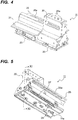
- FIGS. 4 and 5 illustrate perspective views of the supporting member 11 viewed from a front side and a back side, respectively.
- a supporting portion 20 to which the mounting stay 10 is secured, and a curved surface portion 21, which opposes the cover member 13b that covers the turning shaft 4a of the operation panel 4, are located.
- the supporting portion 20 has a top surface where screw holes 20a are formed to fix the mounting stay 10 with screws.
- leaf springs 23 as first urging members are attached at two positions on the lower side.
- a rail 25 is formed including an elongated hole-shaped sliding hole 25a.
- a comb-shaped rack 27 is formed on the lower side, and on a bottom surface 11a of the supporting member 11, a positioning protrusion 29 is located.
- FIG. 6 illustrates a perspective view of the operation panel 4 indicating a state where the cover members 13a and 13b are removed from the state of FIG. 2 .
- FIGS. 7 and 8 each illustrate an enlarged perspective view of the peripheral of the supporting member 11 mounted on the image reading unit 2.
- FIG. 7 indicates a state (see FIG. 1 ) where the operation panel 4 is arranged inside an outer edge of the image forming apparatus 100.
- FIG. 8 indicates a state (see FIG. 12 ) where a part of the operation panel 4 projects outside the outer edge of the image forming apparatus 100.
- FIGS. 6 to 8 a description will be given of a mounting procedure of the operation panel 4 to the image reading unit 2.
- the mounting stay 10 located on the back side of the operation panel 4 is fixed to the supporting portion 20 of the supporting member 11 with screws. This causes the operation panel 4 and the supporting member 11 to be integrated as illustrated in FIG. 3 .
- the supporting member 11 integrated with the operation panel 4 is mounted to the mounting portion 2a.
- two holding screws 30 are inserted into the sliding hole 25a of the rail 25 formed on the back side of the supporting member 11, thus fastening the two holding screws 30 to screw fixing holes (not illustrated) of the mounting portion 2a.
- the holding screw 30 is formed to have an outer diameter of the shaft portion smaller than a width of the sliding hole 25a, and have an outer diameter of the head, formed on an upper end of the shaft portion, larger than the width of the sliding hole 25a. That is, the holding screws 30 hold the rail 25 so as not to be removed from the mounting portion 2a, and movably engage with the sliding hole 25a.
- This configuration slidably supports the supporting member 11 with respect to the mounting portion 2a in the horizontal direction (arrow BB' direction) in a range of the sliding hole 25a.
- the mounting portion 2a includes a rotary damper 33 as a load applying member and a position regulating pin 35.
- the rotary damper 33 engages with the rack 27 of the supporting member 11.
- the rotary damper 33 generates a large load (damping force) when the rotation speed is high, and generates a small load when the rotation speed is low. Then, the rotary damper 33 transmits the load to the rack 27 as a brake force.
- the position regulating pin 35 has a function in abutting contact with an upper side of the rack 27 of the supporting member 11 to generate a friction force, so as to stop the supporting member 11 at any position.
- a lead wire (not illustrated) connected to the image reading unit 2 is connected to a connector 37 located on the back surface of the operation panel 4, and the cover members 13a and 13b are fastened by cover fixing screws 31, thus completing the mounting operation of the operation panel 4 to the image reading unit 2.
- a procedure reverse to the above is performed.
- FIG. 9 illustrates a plan cross-sectional view of a lower portion of the supporting member 11 taken in a horizontal direction
- FIG. 10 illustrates a perspective view of the supporting member 11 mounted on the mounting portion 2a viewed from a front lower side
- FIG. 11 illustrates a vertical cross-sectional view (cross-sectional view in an arrow XI-XI direction in FIG. 5 ) of the supporting member 11 taken in a moving direction (arrow BB' direction).
- the leaf springs 23, which are attached on the front lower side of the supporting member 11 are pressure contacted with the inside of a front wall portion 40 of the mounting portion 2a. This causes the supporting member 11 to be urged to the back side (upward direction in FIG. 9 ) by a reactive force (drag force) acting from the front wall portion 40, thus surely maintaining the engaging state of the rack 27 with the rotary damper 33.
- the mounting portion 2a is made of sheet metal, and is grounded (earthed) via a main body frame (not illustrated) of the image reading unit 2. Then, when the leaf springs 23 contact the mounting portion 2a, the operation panel 4 is grounded (earthed) via the mounting stay 10 and the supporting member 11. This ensures the grounding condition of the operation panel 4 with a simple configuration.
- the mounting portion 2a includes positioning holes 41a and 41b at two positions on the bottom surface such that the positioning protrusion 29 projecting from the bottom surface 11a of the supporting member 11 engages with the positioning hole 41a or 41b.
- the operation panel 4 is arranged on a position (reference position) overlapping the opening/closing cover 8.
- the positioning protrusion 29 engages with the positioning hole 41b, as illustrated in FIG. 13 , the operation panel 4 is arranged on a position (retracted position) retracted to the outside of an opening/closing trajectory of the opening/closing cover 8.
- the positioning protrusion 29 is movably supported in the vertical direction along a guiding portion 50 formed inside the bottom surface 11a of the supporting member 11, so as to be urged downward by a compression spring 51 as a second urging member.
- FIG. 12 illustrates a perspective view of a state where the operation panel 4 is moved to the retracted position viewed from the back side
- FIG. 13 illustrates a perspective view of a state where the opening/closing cover 8 of the image forming apparatus 100 is opened.
- the operation panel 4 When a jam occurs on the paper sheet in the image forming apparatus 100, the operation panel 4 indicates the occurrence of the jam and the occurrence position.
- the occurrence position of the jam is on the conveyance unit 7 arranged in the in-barrel discharge space 6, the opening/closing cover 8 needs to be opened to extract the conveyance unit 7.
- the opening/closing cover 8 cannot be opened.
- the operation panel 4 is slid in the horizontal direction (arrow B direction) to be moved to the retracted position.
- the positioning protrusion 29 is pushed into the inside of the bottom surface 11a of the supporting member 11 against the urging force of the compression spring 51, thus detached from the positioning hole 41a. Since the rotary damper 33 engages with the rack 27 of the supporting member 11, the operation panel 4 receives an appropriate sliding load. Then, the operation panel 4 is prevented from swiftly sliding to the retracted position to be damaged.
- the operation panel 4 When the operation panel 4 is slid to a position where the positioning protrusion 29 faces the positioning hole 41b, the urging force of the compression spring 51 causes the positioning protrusion 29 to project outside the bottom surface 11a, thus engaging the positioning protrusion 29 with the positioning hole 41b.
- An operator can recognize the operation panel 4 to be arranged on the retracted position with a touch (clicking feel) when the positioning protrusion 29 engages with the positioning hole 41b, thus improving the operability.
- the operation panel 4 In a state where the operation panel 4 is moved to the retracted position, the operation panel 4 does not overlap the opening/closing trajectory of the opening/closing cover 8 and an insertion/removal trajectory of the conveyance unit 7 as illustrated in FIG. 13 , thus the opening/closing cover 8 can be opened to extract the conveyance unit 7 from the in-barrel discharge space 6 to the front side. Then, after the jam process terminates, the conveyance unit 7 is inserted into the in-barrel discharge space 6 again, and the operation panel 4 is moved to the reference position after the opening/closing cover 8 is closed, thus returning to the state in FIG. 1 .
- the opening/closing operation of the opening/closing cover 8 and the insertion/removal operation of the conveyance unit 7 can be performed without removing the operation panel 4. This improves the operability in the jam process.
- the supporting member 11 integrated with the operation panel 4 is mounted to the image reading unit 2 by only the holding screws 30, thus ensuring easily mounting the operation panel 4 with only a screwdriver without using an exclusive tool.
- simply removing the cover members 13a and 13b to loosen two holding screws 30 easily removes the operation panel 4.
- the disclosure is not limited to the embodiment described above, and may be variously modified without substantially departing from the spirit and principles of the disclosure.
- the shapes of the respective members and similar factors of the operation panel 4, the supporting member 11, and similar unit indicated in the above embodiment are merely examples, and can be appropriately changed according to, for example, the specification of the image forming apparatus 100.
- While the above embodiment describes the image forming apparatus 100 where the conveyance unit 7 is removably attachably mounted to the in-barrel discharge space 6 and the in-barrel discharge space 6 is openable/closable by the opening/closing cover 8, the disclosure is applicable to an image forming apparatus that includes only one of a removably attachable unit or an opening/closing cover, or an image forming apparatus that includes none of the removably attachable unit or the opening/closing cover.
- moving the operation panel 4 from the reference position to the retracted position improves the visibility and the taking-out property of the paper sheet discharged into the in-barrel discharge space 6.
- the disclosure is obviously applicable to a monochrome printer, a color printer, a color multi-functional peripheral, and a facsimile, not limited to the digital multi-functional peripheral.
- the disclosure is available for a mounting structure of an operation unit for performing a predetermined input operation on the image forming apparatus.
- the use of the disclosure provides an image forming apparatus where the operation unit does not interfere a work area of an image forming apparatus body and operability of the operation unit is ensured.
Landscapes
- Engineering & Computer Science (AREA)
- Multimedia (AREA)
- Signal Processing (AREA)
- Physics & Mathematics (AREA)
- General Physics & Mathematics (AREA)
- Microelectronics & Electronic Packaging (AREA)
- Human Computer Interaction (AREA)
- Electrophotography Configuration And Component (AREA)
- Casings For Electric Apparatus (AREA)
- Accessory Devices And Overall Control Thereof (AREA)
Abstract
Description
- Unless otherwise indicated herein, the description in this section is not prior art to the claims in this application and is not admitted to be prior art by inclusion in this section.
- A typical image forming apparatus such as a copier, a printer, and a facsimile includes an operation unit that indicates operation states of the image forming apparatus and performs predetermined input operations. Some image forming apparatuses employ an in-barrel discharge type that includes an image reading unit on an upper side of an image forming unit, and an in-barrel discharge space between the image reading unit and the image forming unit. The in-barrel discharge type image forming apparatus includes a paper-sheet discharge tray arranged on a bottom surface portion of the in-barrel discharge space, and a paper sheet discharged onto the paper-sheet discharge tray after the termination of image formation is taken out from a front side of an image forming apparatus body.
- In the in-barrel discharge type image forming apparatus, when the operation unit is installed so as to project from the image reading unit on the upper portion of the image forming apparatus to the front side of the image forming apparatus, the operation unit decreases a visibility of the paper sheet discharged into the in-barrel discharge space. Therefore, there has been proposed an image forming apparatus in which a part of the operation unit is depressed toward a rear side of the image reading unit to a position where a part of the paper sheet discharged onto the in-barrel discharge space can be seen from the front obliquely upward.
- There has been proposed another image forming apparatus in which the operation unit is removably attachable to a front surface of the image reading unit located on an upper portion of the in-barrel discharge space and a front surface of the image forming unit located on a lower portion of the in-barrel discharge space.
- An image forming apparatus according to one aspect of the disclosure includes an apparatus main body, an operation unit, and a moving mechanism. The operation unit is mounted to the apparatus main body. The operation unit indicates a state of the apparatus main body and performs an input operation to the apparatus main body. The moving mechanism reciprocatably supports the operation unit between a reference position and a retracted position. The reference position overlaps a work area of the apparatus main body. The retracted position does not overlap the work area.
- These as well as other aspects, advantages, and alternatives will become apparent to those of ordinary skill in the art by reading the following detailed description with reference where appropriate to the accompanying drawings. Further, it should be understood that the description provided in this summary section and elsewhere in this document is intended to illustrate the claimed subject matter by way of example and not by way of limitation.
-
-
FIG. 1 illustrates an external perspective view of an image forming apparatus according to one embodiment of the disclosure; -
FIG. 2 illustrates a perspective view of an operation panel mounted on an image reading unit viewed from a back side; -
FIG. 3 illustrates a perspective view of the operation panel and a supporting member, viewed from the back side in a state where both of them are removed from the image reading unit and; -
FIG. 4 illustrates a perspective view of the supporting member viewed from a front side; -
FIG. 5 illustrates a perspective view of the supporting member viewed from a back side; -
FIG. 6 illustrates a perspective view of the operation panel indicating a state where cover members are removed from the state ofFIG. 2 ; -
FIG. 7 illustrates an enlarged perspective view of a peripheral of the supporting member mounted on the image reading unit, indicating a state where the operation panel is arranged inside an outer edge of the image forming apparatus; -
FIG. 8 illustrates an enlarged perspective view of the peripheral of the supporting member mounted on the image reading unit, indicating a state where a part of the operation panel projects outside the outer edge of the image forming apparatus; -
FIG. 9 illustrates a plan cross-sectional view of a lower portion of the supporting member taken in a horizontal direction; -
FIG. 10 illustrates a perspective view of the supporting member mounted on a mounting portion viewed from a front lower side; -
FIG. 11 illustrates a vertical cross-sectional view of the supporting member taken in a moving direction; -
FIG. 12 illustrates a perspective view of a state where the operation panel is moved to a retracted position viewed from the back side; and -
FIG. 13 illustrates a perspective view of a state where an opening/closing cover of the image forming apparatus is opened. - Example apparatuses are described herein. Other example embodiments or features may further be utilized, and other changes may be made, without departing from the spirit or scope of the subject matter presented herein. In the following detailed description, reference is made to the accompanying drawings, which form a part thereof.
- The example embodiments described herein are not meant to be limiting. It will be readily understood that the aspects of the present disclosure, as generally described herein, and illustrated in the drawings, can be arranged, substituted, combined, separated, and designed in a wide variety of different configurations, all of which are explicitly contemplated herein.
- The following describes an embodiment of the disclosure by referring to the drawings.
FIG. 1 illustrates an external perspective view of animage forming apparatus 100 according to one embodiment of the disclosure. As illustrated inFIG. 1 , theimage forming apparatus 100 is a digital multi-functional peripheral of what is called an in-barrel paper discharge type, and includes a multi-functional peripheralmain body 1 as an apparatus main body and animage reading unit 2 as the apparatus main body located on an upper portion of the multi-functional peripheralmain body 1. - The
image reading unit 2 reads an image of an original document as an electrical signal. Theimage reading unit 2 has the upper portion where a document feeder (not illustrated) that separates the original documents one by one to send into theimage reading unit 2 is attached. The multi-functional peripheralmain body 1 has a lower portion where a papersheet housing space 3 constituted ofsheet feed cassettes 3a to 3c for housing the paper sheets is located. The multi-functional peripheralmain body 1 includes an image forming unit, a transfer unit, a fixing unit (each of which are not illustrated) and similar unit. The image forming unit forms a toner image on a paper sheet based on an electrical signal of a document image read by theimage reading unit 2. The transfer unit transfers the image on the paper sheet fed from the papersheet housing space 3. The fixing unit fixes the toner image transferred on the paper sheet. - An
operation panel 4 as an operation unit is located from a side surface of theimage reading unit 2 so as to overlap the front of the multi-functional peripheralmain body 1. Theoperation panel 4 includes a liquid crystal display, an LED, and similar unit. The liquid crystal display indicates an image formation condition and a printing number of copies, and functions as a touch panel performing an input operation. The LED indicates a state of theimage forming apparatus 100. Furthermore, theoperation panel 4 includes a start button, a stop/clear button, a reset button, and similar button. The start button is a button with which a user instructs to start an image formation. The stop/clear button is a button used in a case where the image formation is aborted or similar case. The reset button is a button used in a case where various settings of theimage forming apparatus 100 are returned to a state of default. The multi-functional peripheralmain body 1 has a side surface (left side surface ofFIG. 1 ) where discharge trays 5a and 5b onto which the paper sheet after the toner image is fixed is discharged. - Between the multi-functional peripheral
main body 1 and theimage reading unit 2, an in-barrel discharge space 6 as a work area (seeFIG. 13 ) is formed to widely open toward a front side of theimage forming apparatus 100. On the upper portion of the in-barrel discharge space 6, a conveyance unit 7 (seeFIG. 13 ) is removably attachably located to guide the paper sheet into a paper-sheet postprocessing unit (not illustrated) where postprocessing is performed on the paper-sheet after the toner image is fixed. InFIG. 1 , the multi-functional peripheralmain body 1 does not include the paper-sheet postprocessing unit, and the paper sheet passed through the fixing unit passes through the inside of theconveyance unit 7 to be discharged onto thedischarge tray 5a or thedischarge tray 5b. Thedischarge tray 5a serves as, for example, a mailbox onto which the paper sheet where an image transmitted by facsimile is printed is discharged. - In front of the in-
barrel discharge space 6, an opening/closing cover 8 is located, and as illustrated inFIG. 1 , closing the opening/closing cover 8 hides inside the in-barrel discharge space 6. -
FIG. 2 illustrates a perspective view of theoperation panel 4 mounted on theimage reading unit 2 viewed from a back side, andFIG. 3 illustrates a perspective view of theoperation panel 4 and a supportingmember 11 as a moving mechanism viewed from the back side in a state where both of them are removed from theimage reading unit 2. Theoperation panel 4 has a back surface where a mounting stay 10 is attached. To the mounting stay 10, a turningshaft 4a (seeFIG. 7 ) of theoperation panel 4 is turnably supported, and turning the turningshaft 4a with respect to themounting stay 10 can adjust an angle of theoperation panel 4 in a vertical direction (arrow AA' direction). - The
mounting stay 10 is secured to the supportingmember 11. The supportingmember 11 is supported movably in a horizontal direction (arrow BB' direction) to a mountingportion 2a as the moving mechanism (seeFIG. 7 ) formed on a front surface of theimage reading unit 2. Accordingly, theoperation panel 4 is mounted on the front surface of theimage reading unit 2 via the mountingstay 10 and the supportingmember 11 such that theoperation panel 4 is movable in the horizontal direction and has the angle in the vertical direction adjustable. In a state where theoperation panel 4 is mounted,cover members stay 10 and the supportingmember 11. -
FIGS. 4 and 5 illustrate perspective views of the supportingmember 11 viewed from a front side and a back side, respectively. As illustrated inFIG. 4 , on the front surface (opposed surface to the operation panel 4) of the supportingmember 11, a supportingportion 20, to which the mountingstay 10 is secured, and acurved surface portion 21, which opposes thecover member 13b that covers the turningshaft 4a of theoperation panel 4, are located. The supportingportion 20 has a top surface where screw holes 20a are formed to fix the mountingstay 10 with screws. On the front surface of the supportingmember 11,leaf springs 23 as first urging members are attached at two positions on the lower side. - As illustrated in
FIG. 5 , on the back surface (opposed surface to the image reading unit 2) of the supportingmember 11, arail 25 is formed including an elongated hole-shaped slidinghole 25a. On the back surface of the supportingmember 11, a comb-shapedrack 27 is formed on the lower side, and on abottom surface 11a of the supportingmember 11, apositioning protrusion 29 is located. -
FIG. 6 illustrates a perspective view of theoperation panel 4 indicating a state where thecover members FIG. 2 . -
FIGS. 7 and8 each illustrate an enlarged perspective view of the peripheral of the supportingmember 11 mounted on theimage reading unit 2.FIG. 7 indicates a state (seeFIG. 1 ) where theoperation panel 4 is arranged inside an outer edge of theimage forming apparatus 100.FIG. 8 indicates a state (seeFIG. 12 ) where a part of theoperation panel 4 projects outside the outer edge of theimage forming apparatus 100. By referring toFIGS. 6 to 8 , a description will be given of a mounting procedure of theoperation panel 4 to theimage reading unit 2. First, the mountingstay 10 located on the back side of theoperation panel 4 is fixed to the supportingportion 20 of the supportingmember 11 with screws. This causes theoperation panel 4 and the supportingmember 11 to be integrated as illustrated inFIG. 3 . - Next, the supporting
member 11 integrated with theoperation panel 4 is mounted to the mountingportion 2a. Specifically, two holdingscrews 30 are inserted into the slidinghole 25a of therail 25 formed on the back side of the supportingmember 11, thus fastening the two holdingscrews 30 to screw fixing holes (not illustrated) of the mountingportion 2a. The holdingscrew 30 is formed to have an outer diameter of the shaft portion smaller than a width of the slidinghole 25a, and have an outer diameter of the head, formed on an upper end of the shaft portion, larger than the width of the slidinghole 25a. That is, the holding screws 30 hold therail 25 so as not to be removed from the mountingportion 2a, and movably engage with the slidinghole 25a. This configuration slidably supports the supportingmember 11 with respect to the mountingportion 2a in the horizontal direction (arrow BB' direction) in a range of the slidinghole 25a. - The mounting
portion 2a includes arotary damper 33 as a load applying member and aposition regulating pin 35. In a state where the supportingmember 11 is mounted to the mountingportion 2a, therotary damper 33 engages with therack 27 of the supportingmember 11. Therotary damper 33 generates a large load (damping force) when the rotation speed is high, and generates a small load when the rotation speed is low. Then, therotary damper 33 transmits the load to therack 27 as a brake force. Theposition regulating pin 35 has a function in abutting contact with an upper side of therack 27 of the supportingmember 11 to generate a friction force, so as to stop the supportingmember 11 at any position. - Afterwards, a lead wire (not illustrated) connected to the
image reading unit 2 is connected to aconnector 37 located on the back surface of theoperation panel 4, and thecover members cover fixing screws 31, thus completing the mounting operation of theoperation panel 4 to theimage reading unit 2. When theoperation panel 4 is removed from theimage reading unit 2, a procedure reverse to the above is performed. -
FIG. 9 illustrates a plan cross-sectional view of a lower portion of the supportingmember 11 taken in a horizontal direction,FIG. 10 illustrates a perspective view of the supportingmember 11 mounted on the mountingportion 2a viewed from a front lower side, andFIG. 11 illustrates a vertical cross-sectional view (cross-sectional view in an arrow XI-XI direction inFIG. 5 ) of the supportingmember 11 taken in a moving direction (arrow BB' direction). As illustrated inFIG. 9 , in a state where the supportingmember 11 is mounted to the mountingportion 2a, theleaf springs 23, which are attached on the front lower side of the supportingmember 11, are pressure contacted with the inside of afront wall portion 40 of the mountingportion 2a. This causes the supportingmember 11 to be urged to the back side (upward direction inFIG. 9 ) by a reactive force (drag force) acting from thefront wall portion 40, thus surely maintaining the engaging state of therack 27 with therotary damper 33. - The mounting
portion 2a is made of sheet metal, and is grounded (earthed) via a main body frame (not illustrated) of theimage reading unit 2. Then, when theleaf springs 23 contact the mountingportion 2a, theoperation panel 4 is grounded (earthed) via the mountingstay 10 and the supportingmember 11. This ensures the grounding condition of theoperation panel 4 with a simple configuration. - As illustrated in
FIG. 10 , the mountingportion 2a includespositioning holes positioning protrusion 29 projecting from thebottom surface 11a of the supportingmember 11 engages with thepositioning hole positioning protrusion 29 engages with thepositioning hole 41a, as illustrated inFIG. 1 , theoperation panel 4 is arranged on a position (reference position) overlapping the opening/closing cover 8. On the other hand, when thepositioning protrusion 29 engages with thepositioning hole 41b, as illustrated inFIG. 13 , theoperation panel 4 is arranged on a position (retracted position) retracted to the outside of an opening/closing trajectory of the opening/closing cover 8. - As illustrated in
FIG. 11 , thepositioning protrusion 29 is movably supported in the vertical direction along a guidingportion 50 formed inside thebottom surface 11a of the supportingmember 11, so as to be urged downward by acompression spring 51 as a second urging member. -
FIG. 12 illustrates a perspective view of a state where theoperation panel 4 is moved to the retracted position viewed from the back side, andFIG. 13 illustrates a perspective view of a state where the opening/closing cover 8 of theimage forming apparatus 100 is opened. By referring toFIGS. 12 and 13 , and referring toFIGS. 1 to 11 as necessary, a description will be given of a jam processing procedure when a jam occurs in the in-barrel discharge space 6. - When a jam occurs on the paper sheet in the
image forming apparatus 100, theoperation panel 4 indicates the occurrence of the jam and the occurrence position. When the occurrence position of the jam is on theconveyance unit 7 arranged in the in-barrel discharge space 6, the opening/closing cover 8 needs to be opened to extract theconveyance unit 7. However, in a state ofFIG. 1 , since a part of theoperation panel 4 overlaps the front side of the opening/closing cover 8, the opening/closing cover 8 cannot be opened. - Then, as illustrated in
FIG. 12 , theoperation panel 4 is slid in the horizontal direction (arrow B direction) to be moved to the retracted position. At this time, thepositioning protrusion 29 is pushed into the inside of thebottom surface 11a of the supportingmember 11 against the urging force of thecompression spring 51, thus detached from thepositioning hole 41a. Since therotary damper 33 engages with therack 27 of the supportingmember 11, theoperation panel 4 receives an appropriate sliding load. Then, theoperation panel 4 is prevented from swiftly sliding to the retracted position to be damaged. - When the
operation panel 4 is slid to a position where thepositioning protrusion 29 faces thepositioning hole 41b, the urging force of thecompression spring 51 causes thepositioning protrusion 29 to project outside thebottom surface 11a, thus engaging thepositioning protrusion 29 with thepositioning hole 41b. An operator can recognize theoperation panel 4 to be arranged on the retracted position with a touch (clicking feel) when thepositioning protrusion 29 engages with thepositioning hole 41b, thus improving the operability. - In a state where the
operation panel 4 is moved to the retracted position, theoperation panel 4 does not overlap the opening/closing trajectory of the opening/closing cover 8 and an insertion/removal trajectory of theconveyance unit 7 as illustrated inFIG. 13 , thus the opening/closing cover 8 can be opened to extract theconveyance unit 7 from the in-barrel discharge space 6 to the front side. Then, after the jam process terminates, theconveyance unit 7 is inserted into the in-barrel discharge space 6 again, and theoperation panel 4 is moved to the reference position after the opening/closing cover 8 is closed, thus returning to the state inFIG. 1 . - According to the configuration of the embodiment, with the
operation panel 4 mounted to theimage reading unit 2 slidable in the horizontal direction, the opening/closing operation of the opening/closing cover 8 and the insertion/removal operation of theconveyance unit 7 can be performed without removing theoperation panel 4. This improves the operability in the jam process. - The supporting
member 11 integrated with theoperation panel 4 is mounted to theimage reading unit 2 by only the holding screws 30, thus ensuring easily mounting theoperation panel 4 with only a screwdriver without using an exclusive tool. On the other hand, in transporting or storing theimage forming apparatus 100, or similar case, simply removing thecover members screws 30 easily removes theoperation panel 4. - The disclosure is not limited to the embodiment described above, and may be variously modified without substantially departing from the spirit and principles of the disclosure. For example, the shapes of the respective members and similar factors of the
operation panel 4, the supportingmember 11, and similar unit indicated in the above embodiment are merely examples, and can be appropriately changed according to, for example, the specification of theimage forming apparatus 100. - While the above embodiment describes the
image forming apparatus 100 where theconveyance unit 7 is removably attachably mounted to the in-barrel discharge space 6 and the in-barrel discharge space 6 is openable/closable by the opening/closing cover 8, the disclosure is applicable to an image forming apparatus that includes only one of a removably attachable unit or an opening/closing cover, or an image forming apparatus that includes none of the removably attachable unit or the opening/closing cover. For example, in a configuration where the in-barrel discharge space 6 includes only a paper sheet tray, moving theoperation panel 4 from the reference position to the retracted position improves the visibility and the taking-out property of the paper sheet discharged into the in-barrel discharge space 6. - While the above embodiment describes the mounting structure of the
operation panel 4 with an exemplary digital multi-functional peripheral indicated as theimage forming apparatus 100 inFIG. 1 , the disclosure is obviously applicable to a monochrome printer, a color printer, a color multi-functional peripheral, and a facsimile, not limited to the digital multi-functional peripheral. - The disclosure is available for a mounting structure of an operation unit for performing a predetermined input operation on the image forming apparatus. The use of the disclosure provides an image forming apparatus where the operation unit does not interfere a work area of an image forming apparatus body and operability of the operation unit is ensured.
- While various aspects and embodiments have been disclosed herein, other aspects and embodiments will be apparent to those skilled in the art. The various aspects and embodiments disclosed herein are for purposes of illustration and are not intended to be limiting, with the true scope and spirit being indicated by the following claims.
Claims (11)
- An image forming apparatus (100), comprising:- an apparatus main body (1);- an operation unit (4) mounted to the apparatus main body (1), the operation unit (4) indicating a state of the apparatus main body (1) and performing an input operation to the apparatus main body (1); and- a moving mechanism (2a,11) reciprocatably supporting the operation unit (4) between a reference position and a retracted position, the reference position overlapping a work area (6) of the apparatus main body (1), and the retracted position not overlapping the work area (6).
- The image forming apparatus (100) according to claim 1,
wherein the moving mechanism (2a,11) includes:- a supporting member (11) secured to a back side of the operation unit (4); and- a mounting portion (2a) located on the apparatus main body (1) side to slidably support the supporting member (11). - The image forming apparatus (100) according to claim 2,
wherein the supporting member (11) includes a rail (25) that has an elongated hole-shaped sliding hole (25a), and
the supporting member (11) is slidably supported to the mounting portion (2a) by holding screws (30) passing through the sliding hole (25a) to be fastened to the mounting portion (2a). - The image forming apparatus (100) according to claim 2 or 3,
wherein the mounting portion (2a) includes a load applying member (33) that generates a load corresponding to a moving speed of the supporting member (11) over a whole region between the reference position and the retracted position. - The image forming apparatus (100) according to claim 4,
wherein the load applying member (33) is a rotary damper (33) that engages with a rack (27) formed on the supporting member (11). - The image forming apparatus (100) according to claim 4 or 5,
wherein on the supporting member (11), a first urging member (23) is attached to urge the supporting member (11) in an engaging direction of the rack (27) with the rotary damper (33). - The image forming apparatus (100) according to claim 6,
wherein the first urging member (23) doubles as a grounding member that grounds the operation unit (4) via the supporting member (11) and the mounting portion (2a). - The image forming apparatus (100) according to one of the claims 1 to 7 in combination with claim 2,
wherein the supporting member (11) includes a positioning protrusion (29) that engages with any of a plurality of positioning holes (41) formed on the mounting portion (2a) when the supporting member (11) is arranged on any of a plurality of positions including the reference position and the retracted position. - The image forming apparatus (100) according to claim 8,
wherein the positioning protrusion (29) is supported protrudable and retractable with respect to the supporting member (11) and urged by a second urging member (51) in a projecting direction, and the positioning protrusion (29) projects out of the supporting member (11) by an urging force of the second urging member (51) at a position facing the positioning hole (41), so as to engage with the positioning hole (41). - The image forming apparatus (100) according to one of the claims 1 to 9,
wherein the work area (6) is an in-barrel discharge space (6) that is formed between an image reading unit (2) and an image forming unit, the image reading unit (2) reads an image of an original document, and the image forming unit forms a toner image on a recording medium based on an electrical signal of the document image read by the image reading unit (2). - The image forming apparatus (100) according to one of the claims 1 to 10,
wherein the work area (6) is a region including at least one of an opening/closing trajectory of an opening/closing cover (8) openable/closable with respect to the apparatus main body (1) and an attachment/removal trajectory of a unit (7) removably attachable with respect to the apparatus main body (1).
Applications Claiming Priority (1)
| Application Number | Priority Date | Filing Date | Title |
|---|---|---|---|
| JP2016152412A JP6536513B2 (en) | 2016-08-03 | 2016-08-03 | Image forming device |
Publications (2)
| Publication Number | Publication Date |
|---|---|
| EP3279742A1 true EP3279742A1 (en) | 2018-02-07 |
| EP3279742B1 EP3279742B1 (en) | 2019-05-22 |
Family
ID=59485170
Family Applications (1)
| Application Number | Title | Priority Date | Filing Date |
|---|---|---|---|
| EP17182983.1A Active EP3279742B1 (en) | 2016-08-03 | 2017-07-25 | Image forming apparatus with movable control panel |
Country Status (4)
| Country | Link |
|---|---|
| US (1) | US10165139B2 (en) |
| EP (1) | EP3279742B1 (en) |
| JP (1) | JP6536513B2 (en) |
| CN (1) | CN107688280B (en) |
Cited By (1)
| Publication number | Priority date | Publication date | Assignee | Title |
|---|---|---|---|---|
| US20230147199A1 (en) * | 2021-11-09 | 2023-05-11 | Canon Kabushiki Kaisha | Image forming apparatus |
Families Citing this family (5)
| Publication number | Priority date | Publication date | Assignee | Title |
|---|---|---|---|---|
| JP6685820B2 (en) | 2016-04-25 | 2020-04-22 | キヤノン株式会社 | Input device and image forming device |
| JP6740063B2 (en) * | 2016-09-09 | 2020-08-12 | キヤノン株式会社 | Image forming device |
| US10671004B2 (en) * | 2018-09-10 | 2020-06-02 | Fuji Xerox Co., Ltd. | Movable holding device, operation unit displacement device, and image forming system |
| JP7210950B2 (en) * | 2018-09-10 | 2023-01-24 | 富士フイルムビジネスイノベーション株式会社 | Movable holder and imaging system |
| JP7419982B2 (en) * | 2020-06-10 | 2024-01-23 | コニカミノルタ株式会社 | Image forming device |
Citations (3)
| Publication number | Priority date | Publication date | Assignee | Title |
|---|---|---|---|---|
| JP2003312088A (en) * | 2002-04-23 | 2003-11-06 | Murata Mach Ltd | control panel |
| US20050175371A1 (en) * | 2004-02-10 | 2005-08-11 | Kabushiki Kaisha Toshiba | Image forming apparatus |
| US20110080620A1 (en) * | 2009-10-07 | 2011-04-07 | Samsung Electronics Co., Ltd | Operating device usable with image forming apparatus and image forming apparatus having the same |
Family Cites Families (14)
| Publication number | Priority date | Publication date | Assignee | Title |
|---|---|---|---|---|
| US5391070A (en) * | 1990-11-02 | 1995-02-21 | Fanuc Ltd | Injection molding machine equipped with a movable display unit |
| US6493600B1 (en) * | 1998-02-05 | 2002-12-10 | Canon Kabushiki Kaisha | Semiconductor manufacturing apparatus |
| JP2001130089A (en) | 1999-11-04 | 2001-05-15 | Canon Inc | Image forming device |
| JP2003076248A (en) * | 2001-06-19 | 2003-03-14 | Canon Inc | Image forming apparatus with separation operation unit |
| JP2006010867A (en) * | 2004-06-23 | 2006-01-12 | Kyocera Mita Corp | Image processor |
| JP2004355019A (en) | 2004-08-02 | 2004-12-16 | Ricoh Co Ltd | Image forming device |
| JP4592455B2 (en) * | 2005-03-15 | 2010-12-01 | 京セラミタ株式会社 | Operation panel attitude change mechanism of image forming apparatus |
| JP4825581B2 (en) * | 2005-08-22 | 2011-11-30 | 京セラミタ株式会社 | Image forming apparatus |
| US7542699B2 (en) * | 2005-08-22 | 2009-06-02 | Kyocera Mita Corporation | Image forming apparatus having slidable control portion |
| JP2007316438A (en) | 2006-05-26 | 2007-12-06 | Murata Mach Ltd | Image forming apparatus |
| JP4906082B2 (en) * | 2006-09-11 | 2012-03-28 | 株式会社リコー | Angle adjusting device and image forming apparatus |
| KR20160011101A (en) * | 2014-07-21 | 2016-01-29 | 삼성전자주식회사 | image forming apparatus |
| JP2017173386A (en) * | 2016-03-18 | 2017-09-28 | コニカミノルタ株式会社 | Image forming apparatus |
| JP6812183B2 (en) * | 2016-09-29 | 2021-01-13 | キヤノン株式会社 | Image forming device |
-
2016
- 2016-08-03 JP JP2016152412A patent/JP6536513B2/en active Active
-
2017
- 2017-07-05 CN CN201710545585.9A patent/CN107688280B/en active Active
- 2017-07-07 US US15/643,839 patent/US10165139B2/en active Active
- 2017-07-25 EP EP17182983.1A patent/EP3279742B1/en active Active
Patent Citations (3)
| Publication number | Priority date | Publication date | Assignee | Title |
|---|---|---|---|---|
| JP2003312088A (en) * | 2002-04-23 | 2003-11-06 | Murata Mach Ltd | control panel |
| US20050175371A1 (en) * | 2004-02-10 | 2005-08-11 | Kabushiki Kaisha Toshiba | Image forming apparatus |
| US20110080620A1 (en) * | 2009-10-07 | 2011-04-07 | Samsung Electronics Co., Ltd | Operating device usable with image forming apparatus and image forming apparatus having the same |
Cited By (2)
| Publication number | Priority date | Publication date | Assignee | Title |
|---|---|---|---|---|
| US20230147199A1 (en) * | 2021-11-09 | 2023-05-11 | Canon Kabushiki Kaisha | Image forming apparatus |
| US12110206B2 (en) * | 2021-11-09 | 2024-10-08 | Canon Kabushiki Kaisha | Image forming apparatus |
Also Published As
| Publication number | Publication date |
|---|---|
| EP3279742B1 (en) | 2019-05-22 |
| US20180041649A1 (en) | 2018-02-08 |
| US10165139B2 (en) | 2018-12-25 |
| JP2018020476A (en) | 2018-02-08 |
| JP6536513B2 (en) | 2019-07-03 |
| CN107688280A (en) | 2018-02-13 |
| CN107688280B (en) | 2020-04-21 |
Similar Documents
| Publication | Publication Date | Title |
|---|---|---|
| EP3279742B1 (en) | Image forming apparatus with movable control panel | |
| JP5783845B2 (en) | Image forming apparatus | |
| US9994411B2 (en) | Sheet tray, conveyance unit and image recording apparatus | |
| US9796541B2 (en) | Sheet feeder and image forming apparatus | |
| US9592975B2 (en) | Paper transfer device | |
| US10678179B2 (en) | Image forming apparatus | |
| JP2019035823A (en) | Compound machine | |
| US11535468B2 (en) | Recording apparatus | |
| US5375826A (en) | Paper tray control of a sheet feeder having biased nip rollers cooperative with the positioning of a paper tray | |
| JP6645117B2 (en) | Recording device | |
| US9131092B2 (en) | Image reading device | |
| CN114435996B (en) | Image processing device | |
| US10407264B2 (en) | Medium transporting device, image reading apparatus, and opening/closing device | |
| JP5934676B2 (en) | Image forming apparatus | |
| US9783386B2 (en) | Sheet conveying apparatus | |
| JP7392257B2 (en) | Sheet conveyance device and image recording device | |
| JP6031788B2 (en) | Feeding device and recording device | |
| US20250304387A1 (en) | Medium conveyance apparatus and recording apparatus | |
| JP7000717B2 (en) | Image forming device | |
| JP2009131968A (en) | Image forming apparatus | |
| US10668756B2 (en) | Printer | |
| JP2009184799A (en) | Image forming apparatus | |
| JP2018127310A (en) | Sheet support device and image forming apparatus | |
| JP6892624B2 (en) | Feeding device and recording device | |
| JP2018165212A (en) | Sheet conveying apparatus and image recording apparatus |
Legal Events
| Date | Code | Title | Description |
|---|---|---|---|
| PUAI | Public reference made under article 153(3) epc to a published international application that has entered the european phase |
Free format text: ORIGINAL CODE: 0009012 |
|
| STAA | Information on the status of an ep patent application or granted ep patent |
Free format text: STATUS: THE APPLICATION HAS BEEN PUBLISHED |
|
| AK | Designated contracting states |
Kind code of ref document: A1 Designated state(s): AL AT BE BG CH CY CZ DE DK EE ES FI FR GB GR HR HU IE IS IT LI LT LU LV MC MK MT NL NO PL PT RO RS SE SI SK SM TR |
|
| AX | Request for extension of the european patent |
Extension state: BA ME |
|
| STAA | Information on the status of an ep patent application or granted ep patent |
Free format text: STATUS: REQUEST FOR EXAMINATION WAS MADE |
|
| 17P | Request for examination filed |
Effective date: 20180801 |
|
| RBV | Designated contracting states (corrected) |
Designated state(s): AL AT BE BG CH CY CZ DE DK EE ES FI FR GB GR HR HU IE IS IT LI LT LU LV MC MK MT NL NO PL PT RO RS SE SI SK SM TR |
|
| GRAP | Despatch of communication of intention to grant a patent |
Free format text: ORIGINAL CODE: EPIDOSNIGR1 |
|
| STAA | Information on the status of an ep patent application or granted ep patent |
Free format text: STATUS: GRANT OF PATENT IS INTENDED |
|
| INTG | Intention to grant announced |
Effective date: 20181129 |
|
| GRAS | Grant fee paid |
Free format text: ORIGINAL CODE: EPIDOSNIGR3 |
|
| GRAA | (expected) grant |
Free format text: ORIGINAL CODE: 0009210 |
|
| STAA | Information on the status of an ep patent application or granted ep patent |
Free format text: STATUS: THE PATENT HAS BEEN GRANTED |
|
| AK | Designated contracting states |
Kind code of ref document: B1 Designated state(s): AL AT BE BG CH CY CZ DE DK EE ES FI FR GB GR HR HU IE IS IT LI LT LU LV MC MK MT NL NO PL PT RO RS SE SI SK SM TR |
|
| REG | Reference to a national code |
Ref country code: GB Ref legal event code: FG4D |
|
| REG | Reference to a national code |
Ref country code: CH Ref legal event code: EP |
|
| REG | Reference to a national code |
Ref country code: IE Ref legal event code: FG4D |
|
| REG | Reference to a national code |
Ref country code: DE Ref legal event code: R096 Ref document number: 602017004087 Country of ref document: DE |
|
| REG | Reference to a national code |
Ref country code: AT Ref legal event code: REF Ref document number: 1136841 Country of ref document: AT Kind code of ref document: T Effective date: 20190615 |
|
| REG | Reference to a national code |
Ref country code: NL Ref legal event code: MP Effective date: 20190522 |
|
| REG | Reference to a national code |
Ref country code: LT Ref legal event code: MG4D |
|
| PG25 | Lapsed in a contracting state [announced via postgrant information from national office to epo] |
Ref country code: SE Free format text: LAPSE BECAUSE OF FAILURE TO SUBMIT A TRANSLATION OF THE DESCRIPTION OR TO PAY THE FEE WITHIN THE PRESCRIBED TIME-LIMIT Effective date: 20190522 Ref country code: LT Free format text: LAPSE BECAUSE OF FAILURE TO SUBMIT A TRANSLATION OF THE DESCRIPTION OR TO PAY THE FEE WITHIN THE PRESCRIBED TIME-LIMIT Effective date: 20190522 Ref country code: NL Free format text: LAPSE BECAUSE OF FAILURE TO SUBMIT A TRANSLATION OF THE DESCRIPTION OR TO PAY THE FEE WITHIN THE PRESCRIBED TIME-LIMIT Effective date: 20190522 Ref country code: PT Free format text: LAPSE BECAUSE OF FAILURE TO SUBMIT A TRANSLATION OF THE DESCRIPTION OR TO PAY THE FEE WITHIN THE PRESCRIBED TIME-LIMIT Effective date: 20190922 Ref country code: AL Free format text: LAPSE BECAUSE OF FAILURE TO SUBMIT A TRANSLATION OF THE DESCRIPTION OR TO PAY THE FEE WITHIN THE PRESCRIBED TIME-LIMIT Effective date: 20190522 Ref country code: NO Free format text: LAPSE BECAUSE OF FAILURE TO SUBMIT A TRANSLATION OF THE DESCRIPTION OR TO PAY THE FEE WITHIN THE PRESCRIBED TIME-LIMIT Effective date: 20190822 Ref country code: HR Free format text: LAPSE BECAUSE OF FAILURE TO SUBMIT A TRANSLATION OF THE DESCRIPTION OR TO PAY THE FEE WITHIN THE PRESCRIBED TIME-LIMIT Effective date: 20190522 Ref country code: FI Free format text: LAPSE BECAUSE OF FAILURE TO SUBMIT A TRANSLATION OF THE DESCRIPTION OR TO PAY THE FEE WITHIN THE PRESCRIBED TIME-LIMIT Effective date: 20190522 |
|
| PG25 | Lapsed in a contracting state [announced via postgrant information from national office to epo] |
Ref country code: BG Free format text: LAPSE BECAUSE OF FAILURE TO SUBMIT A TRANSLATION OF THE DESCRIPTION OR TO PAY THE FEE WITHIN THE PRESCRIBED TIME-LIMIT Effective date: 20190822 Ref country code: GR Free format text: LAPSE BECAUSE OF FAILURE TO SUBMIT A TRANSLATION OF THE DESCRIPTION OR TO PAY THE FEE WITHIN THE PRESCRIBED TIME-LIMIT Effective date: 20190823 Ref country code: RS Free format text: LAPSE BECAUSE OF FAILURE TO SUBMIT A TRANSLATION OF THE DESCRIPTION OR TO PAY THE FEE WITHIN THE PRESCRIBED TIME-LIMIT Effective date: 20190522 Ref country code: LV Free format text: LAPSE BECAUSE OF FAILURE TO SUBMIT A TRANSLATION OF THE DESCRIPTION OR TO PAY THE FEE WITHIN THE PRESCRIBED TIME-LIMIT Effective date: 20190522 |
|
| REG | Reference to a national code |
Ref country code: AT Ref legal event code: MK05 Ref document number: 1136841 Country of ref document: AT Kind code of ref document: T Effective date: 20190522 |
|
| PG25 | Lapsed in a contracting state [announced via postgrant information from national office to epo] |
Ref country code: EE Free format text: LAPSE BECAUSE OF FAILURE TO SUBMIT A TRANSLATION OF THE DESCRIPTION OR TO PAY THE FEE WITHIN THE PRESCRIBED TIME-LIMIT Effective date: 20190522 Ref country code: AT Free format text: LAPSE BECAUSE OF FAILURE TO SUBMIT A TRANSLATION OF THE DESCRIPTION OR TO PAY THE FEE WITHIN THE PRESCRIBED TIME-LIMIT Effective date: 20190522 Ref country code: DK Free format text: LAPSE BECAUSE OF FAILURE TO SUBMIT A TRANSLATION OF THE DESCRIPTION OR TO PAY THE FEE WITHIN THE PRESCRIBED TIME-LIMIT Effective date: 20190522 Ref country code: SK Free format text: LAPSE BECAUSE OF FAILURE TO SUBMIT A TRANSLATION OF THE DESCRIPTION OR TO PAY THE FEE WITHIN THE PRESCRIBED TIME-LIMIT Effective date: 20190522 Ref country code: CZ Free format text: LAPSE BECAUSE OF FAILURE TO SUBMIT A TRANSLATION OF THE DESCRIPTION OR TO PAY THE FEE WITHIN THE PRESCRIBED TIME-LIMIT Effective date: 20190522 Ref country code: RO Free format text: LAPSE BECAUSE OF FAILURE TO SUBMIT A TRANSLATION OF THE DESCRIPTION OR TO PAY THE FEE WITHIN THE PRESCRIBED TIME-LIMIT Effective date: 20190522 |
|
| REG | Reference to a national code |
Ref country code: DE Ref legal event code: R097 Ref document number: 602017004087 Country of ref document: DE |
|
| PG25 | Lapsed in a contracting state [announced via postgrant information from national office to epo] |
Ref country code: MC Free format text: LAPSE BECAUSE OF FAILURE TO SUBMIT A TRANSLATION OF THE DESCRIPTION OR TO PAY THE FEE WITHIN THE PRESCRIBED TIME-LIMIT Effective date: 20190522 Ref country code: IT Free format text: LAPSE BECAUSE OF FAILURE TO SUBMIT A TRANSLATION OF THE DESCRIPTION OR TO PAY THE FEE WITHIN THE PRESCRIBED TIME-LIMIT Effective date: 20190522 Ref country code: SM Free format text: LAPSE BECAUSE OF FAILURE TO SUBMIT A TRANSLATION OF THE DESCRIPTION OR TO PAY THE FEE WITHIN THE PRESCRIBED TIME-LIMIT Effective date: 20190522 |
|
| PLBE | No opposition filed within time limit |
Free format text: ORIGINAL CODE: 0009261 |
|
| STAA | Information on the status of an ep patent application or granted ep patent |
Free format text: STATUS: NO OPPOSITION FILED WITHIN TIME LIMIT |
|
| PG25 | Lapsed in a contracting state [announced via postgrant information from national office to epo] |
Ref country code: TR Free format text: LAPSE BECAUSE OF FAILURE TO SUBMIT A TRANSLATION OF THE DESCRIPTION OR TO PAY THE FEE WITHIN THE PRESCRIBED TIME-LIMIT Effective date: 20190522 |
|
| REG | Reference to a national code |
Ref country code: BE Ref legal event code: MM Effective date: 20190731 |
|
| 26N | No opposition filed |
Effective date: 20200225 |
|
| PG25 | Lapsed in a contracting state [announced via postgrant information from national office to epo] |
Ref country code: PL Free format text: LAPSE BECAUSE OF FAILURE TO SUBMIT A TRANSLATION OF THE DESCRIPTION OR TO PAY THE FEE WITHIN THE PRESCRIBED TIME-LIMIT Effective date: 20190522 |
|
| PG25 | Lapsed in a contracting state [announced via postgrant information from national office to epo] |
Ref country code: BE Free format text: LAPSE BECAUSE OF NON-PAYMENT OF DUE FEES Effective date: 20190731 Ref country code: SI Free format text: LAPSE BECAUSE OF FAILURE TO SUBMIT A TRANSLATION OF THE DESCRIPTION OR TO PAY THE FEE WITHIN THE PRESCRIBED TIME-LIMIT Effective date: 20190522 Ref country code: LU Free format text: LAPSE BECAUSE OF NON-PAYMENT OF DUE FEES Effective date: 20190725 |
|
| PG25 | Lapsed in a contracting state [announced via postgrant information from national office to epo] |
Ref country code: FR Free format text: LAPSE BECAUSE OF NON-PAYMENT OF DUE FEES Effective date: 20190731 |
|
| PG25 | Lapsed in a contracting state [announced via postgrant information from national office to epo] |
Ref country code: IE Free format text: LAPSE BECAUSE OF NON-PAYMENT OF DUE FEES Effective date: 20190725 |
|
| PG25 | Lapsed in a contracting state [announced via postgrant information from national office to epo] |
Ref country code: ES Free format text: LAPSE BECAUSE OF FAILURE TO SUBMIT A TRANSLATION OF THE DESCRIPTION OR TO PAY THE FEE WITHIN THE PRESCRIBED TIME-LIMIT Effective date: 20190522 |
|
| REG | Reference to a national code |
Ref country code: CH Ref legal event code: PL |
|
| PG25 | Lapsed in a contracting state [announced via postgrant information from national office to epo] |
Ref country code: CH Free format text: LAPSE BECAUSE OF NON-PAYMENT OF DUE FEES Effective date: 20200731 Ref country code: LI Free format text: LAPSE BECAUSE OF NON-PAYMENT OF DUE FEES Effective date: 20200731 |
|
| PG25 | Lapsed in a contracting state [announced via postgrant information from national office to epo] |
Ref country code: CY Free format text: LAPSE BECAUSE OF FAILURE TO SUBMIT A TRANSLATION OF THE DESCRIPTION OR TO PAY THE FEE WITHIN THE PRESCRIBED TIME-LIMIT Effective date: 20190522 |
|
| PG25 | Lapsed in a contracting state [announced via postgrant information from national office to epo] |
Ref country code: IS Free format text: LAPSE BECAUSE OF FAILURE TO SUBMIT A TRANSLATION OF THE DESCRIPTION OR TO PAY THE FEE WITHIN THE PRESCRIBED TIME-LIMIT Effective date: 20190922 |
|
| PG25 | Lapsed in a contracting state [announced via postgrant information from national office to epo] |
Ref country code: MT Free format text: LAPSE BECAUSE OF FAILURE TO SUBMIT A TRANSLATION OF THE DESCRIPTION OR TO PAY THE FEE WITHIN THE PRESCRIBED TIME-LIMIT Effective date: 20190522 Ref country code: HU Free format text: LAPSE BECAUSE OF FAILURE TO SUBMIT A TRANSLATION OF THE DESCRIPTION OR TO PAY THE FEE WITHIN THE PRESCRIBED TIME-LIMIT; INVALID AB INITIO Effective date: 20170725 |
|
| PG25 | Lapsed in a contracting state [announced via postgrant information from national office to epo] |
Ref country code: MK Free format text: LAPSE BECAUSE OF FAILURE TO SUBMIT A TRANSLATION OF THE DESCRIPTION OR TO PAY THE FEE WITHIN THE PRESCRIBED TIME-LIMIT Effective date: 20190522 |
|
| P01 | Opt-out of the competence of the unified patent court (upc) registered |
Effective date: 20230420 |
|
| PGFP | Annual fee paid to national office [announced via postgrant information from national office to epo] |
Ref country code: DE Payment date: 20250620 Year of fee payment: 9 |
|
| PGFP | Annual fee paid to national office [announced via postgrant information from national office to epo] |
Ref country code: GB Payment date: 20260618 Year of fee payment: 10 |