EP3279701A1 - Security inspection apparatus and method - Google Patents
Security inspection apparatus and method Download PDFInfo
- Publication number
- EP3279701A1 EP3279701A1 EP17173471.8A EP17173471A EP3279701A1 EP 3279701 A1 EP3279701 A1 EP 3279701A1 EP 17173471 A EP17173471 A EP 17173471A EP 3279701 A1 EP3279701 A1 EP 3279701A1
- Authority
- EP
- European Patent Office
- Prior art keywords
- inspected object
- distance
- emitting device
- radiation emitting
- height
- Prior art date
- Legal status (The legal status is an assumption and is not a legal conclusion. Google has not performed a legal analysis and makes no representation as to the accuracy of the status listed.)
- Granted
Links
Images




Classifications
-
- G—PHYSICS
- G01—MEASURING; TESTING
- G01V—GEOPHYSICS; GRAVITATIONAL MEASUREMENTS; DETECTING MASSES OR OBJECTS; TAGS
- G01V5/00—Prospecting or detecting by the use of ionising radiation, e.g. of natural or induced radioactivity
- G01V5/20—Detecting prohibited goods, e.g. weapons, explosives, hazardous substances, contraband or smuggled objects
- G01V5/22—Active interrogation, i.e. by irradiating objects or goods using external radiation sources, e.g. using gamma rays or cosmic rays
- G01V5/222—Active interrogation, i.e. by irradiating objects or goods using external radiation sources, e.g. using gamma rays or cosmic rays measuring scattered radiation
-
- G—PHYSICS
- G01—MEASURING; TESTING
- G01N—INVESTIGATING OR ANALYSING MATERIALS BY DETERMINING THEIR CHEMICAL OR PHYSICAL PROPERTIES
- G01N23/00—Investigating or analysing materials by the use of wave or particle radiation, e.g. X-rays or neutrons, not covered by groups G01N3/00 – G01N17/00, G01N21/00 or G01N22/00
- G01N23/20—Investigating or analysing materials by the use of wave or particle radiation, e.g. X-rays or neutrons, not covered by groups G01N3/00 – G01N17/00, G01N21/00 or G01N22/00 by using diffraction of the radiation by the materials, e.g. for investigating crystal structure; by using scattering of the radiation by the materials, e.g. for investigating non-crystalline materials; by using reflection of the radiation by the materials
- G01N23/203—Measuring back scattering
Definitions
- the present invention relates to the technical field of radiation, and particularly a security inspection apparatus and method.
- X-ray backscatter imaging is getting more and more important in security inspection because it can well detect the material of an object with a low atomic number.
- An embodiment is as follows: a flywheel rotates about a radiation source to form a pencil beam, and the pencil beam interacts with an inspected object to form a flying spot through Compton scattering.
- a back-scatter detector collects X-ray backscatter rays of the flying spot at any time, and after processing, information of the material is obtained, i.e., a backscatter image is formed. After continuous scanning, internal information of the whole object inspected can be processed and obtained, and objects with a lower atomic number, e.g., contraband goods such as explosives, drugs, hidden in concealed locations such as vehicle door interlayer, vehicle bottom, could be highlighted.
- contraband goods such as explosives, drugs, hidden in concealed locations such as vehicle door interlayer, vehicle bottom
- the existing flying point device operates as follows: a radiation source generates fan-shaped X-rays that pass through a rotating shield with multiple collimating holes to continuously generate a pencil beam for achieving a first dimensional scanning, and achieving a second-dimensional scanning by rotating or translating the rays to scan sectors.
- the existing backscatter device is stationary in its scanning angle and scanning position including vertical and horizontal position, the view angle of the image is possibly bad, such that occlusion or overlap is formed between internal structures of the inspected objects, and suspicious goods cannot be highly identified under this angle.
- An object of this invention is to provide a security inspection approach that can flexibly adjust the position of the ray source according to the condition of the inspected object.
- a security inspection apparatus comprising: a radiation emitting device, a back-scatter detector located between the radiation emitting device and an inspected object, a size-distance detecting device located between the radiation emitting device and the inspected object, for detecting a size of the inspected object and/or a distance from the inspected object, and an orientation adjusting device for adjusting a orientation of the radiation emitting device according to the size of the inspected object and/or the distance between the inspected object and the size-distance detecting device.
- the orientation adjusting device further adjusts an angle of the back-scatter detector according to the orientation of the radiation emitting device.
- the size-distance detecting device comprises a plurality of sensors for determining a height of the inspected object by judging a height of an obstacle in front of the sensors.
- the size-distance detecting device further comprises: a camera located on a perpendicular bisector of the security inspection apparatus and the inspected object in a horizontal plane, and shoots in the direction of the perpendicular bisector; a calculating device acquires an image height of the inspected object and an image distance between the inspected object and the size-distance detecting device in a video image shot by the camera, and determines a distance between the inspected object and the size-distance detecting device from a ratio of the image distance to the image height and the height of the inspected object detected by the sensor.
- the orientation adjusting device adjusts a height and an emission angle of the radiation emitting device based on a predetermined gear, according to the height of the inspected object and/or the distance between the inspected object and the size-distance detecting device.
- the orientation adjusting device adjusts a distance between the radiation emitting device and the inspected object based on a predetermined gear, according to the height of the inspected object and/or the distance between the inspected object and the size-distance detecting device.
- the orientation adjusting device determines an ideal height and an ideal emission angle of the radiation emitting device based on a predetermined strategy, from the height of the inspected object and/or the distance between the inspected object and the size-distance detecting device, and adjusts the height and the emission angle of the radiation emitting device according to the ideal height and the ideal emission angle.
- the orientation adjusting device determines an ideal distance between the radiation emitting device and the inspected object based on a predetermined strategy, from the height of the inspected object and/or the distance between the inspected object and the size-distance detecting device, and adjusts the distance between the radiation emitting device and the inspected object according to the ideal distance.
- the orientation adjusting device adjusts an angle of the back-scatter detector based on a predetermined gear, according to the height and the emission angle of the radiation emitting device, or determines an ideal angle of the back-scatter detector from the height and the emission angle of the radiation emitting device, and adjusts the angle of the back-scatter detector according to the ideal angle.
- the back-scatter detector is arc-shaped.
- the radiation emitting device comprises: a ray source located in a center of the radiation emitting device; and a spatial modulator located between the radiation source and the back-scatter detector, comprising a fixed shielding plate and a rotating shielding plate which located between the inspected object and the fixed shielding plate, and comprises more than one hole.
- the security inspection apparatus further comprises a transportation facility for carrying and moving the security inspection apparatus.
- the security inspection apparatus further comprises: a control device for manually controlling the orientation adjusting device to perform the adjusting operation according to detection needs.
- the security inspection apparatus further comprises a processor for receiving detection signals from the back-scatter detector.
- Such a security inspection apparatus can detect size and position information of the inspected object, and automatically adjust the orientation of the radiation emitting device according to the size and position of the inspected object, thereby reducing or avoiding detection dead angles, and improving accuracy of the detection.
- a security inspection method comprising: acquiring a height of an inspected object and a distance between the inspected object and a size-distance detecting device; adjusting an orientation of a radiation emitting device according to the height of the inspected object and the distance between the inspected object and the size-distance detecting device; acquiring backscatter detection data by a back-scatter detector; and acquiring a detection result based on the backscatter detection data.
- the security inspection method further comprise: adjusting an angle of the back-scatter detector according to the orientation of the radiation emitting device.
- acquiring a height of an inspected object comprises: the height of the inspected object is acquired by using a plurality of sensors acquire to judge a height of an obstacle in front of the sensors.
- acquiring a distance between the inspected object and the size-distance detecting device comprises: a video image is acquired by using a camera located on a perpendicular bisector of the security inspection apparatus and the inspected object in a horizontal plane, and shooting in the direction of the perpendicular bisector; acquiring an image height of the inspected object and an image distance between the inspected object and the size-distance detecting device in the video image, and determining a distance between the inspected object and the size-distance detecting device from a ratio of the image distance to the image height and the height of the inspected object.
- adjusting the orientation of the radiation emitting device according to the height of the inspected object and the distance between the inspected object and the size-distance detecting device further comprises: adjusting a height and a emission angle of the radiation emitting device based on a predetermined gear, according to the height of the inspected object and/or the distance between the inspected object and the size-distance detecting device.
- adjusting the orientation of the radiation emitting device according to the height of the inspected object and the distance between the inspected object and the size-distance detecting device further comprises: adjusting the distance between the radiation emitting device and the inspected object based on a predetermined gear, according to the height of the inspected object and the distance between the inspected object and the size-distance detecting device.
- adjusting the orientation of the radiation emitting device according to the height of the inspected object and the distance between the inspected object and a size-distance detecting device further comprises: determining an ideal height and an ideal emission angle of the radiation emitting device based on a predetermined strategy, from the height of the inspected object and/or the distance between the inspected object and the size-distance detecting device, and adjusting the height and the emission angle of the radiation emitting device according to the ideal height and the ideal emission angle.
- adjusting the orientation of the radiation emitting device according to the height of the inspected object and the distance between the inspected object and a size-distance detecting device further comprises: determining an ideal distance between the radiation emitting device and the inspected object using a predetermined strategy from the height of the inspected object and/or the distance between the inspected object and a size-distance detecting device, and adjusting the distance between the radiation emitting device and the size-distance detecting device according to the ideal distance.
- adjusting an angle of the back-scatter detector according to the orientation of the radiation emitting device further comprises: adjusting the angle of the back-scatter detector based on a predetermined gear, according to the height and the emission angle of the radiation emitting device.
- adjusting an angle of the back-scatter detector according to the orientation of the radiation emitting device further comprises: determining an ideal angle of the back-scatter detector from the height and the emission angle of the radiation emitting device, and adjusting the angle of the back-scatter detector according to the ideal angle.
- the security inspection method further comprise: manually adjusting the orientation of the radiation emitting device and/or the angle of the back-scatter detector according to detection needs.
- manually adjusting the orientation of the radiation emitting device and/or the angle of the back-scatter detector according to detection needs comprises: manually adjusting the orientation of the radiation emitting device and/or the angle of the back-scatter detector for many times according to detection needs; acquiring backscatter detection data by a back-scatter detector comprises acquiring backscatter detection data after each time adjusting the orientation of the radiation emitting device and the angle of the back-scatter detector; and acquiring a detection result based on the backscatter detection data comprises: making a comprehensive analysis of the backscatter detection data acquired each time to determine the detection result.
- the existing X-ray inspection apparatus cannot make real-time adjustments according to the size and position of the inspected object since components thereof have relatively fixed positions, which possibly will result in a poor effect of the backscatter scan image: for example, if the ray emission position is fixed, the view angle of the output image perhaps will be bad, and internal structures form occlusion or overlap, and suspicious objects cannot be well identified.
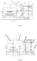
- Fig.1 is a schematic diagram of the security inspection apparatus according to one embodiment of this invention.
- the radiation emitting device 1 is capable of emitting rays 3 to an inspected object 4.
- the back-scatter detector is capable of acquiring backscatter rays and generating backscatter data.
- the security inspection apparatus further comprises a size-distance detecting device 5 located between the radiation emitting device 1 and the inspected object 4.
- the size-distance detecting device 5 is capable of detecting a size of the inspected object 4 and a distance from the inspected object 4.
- the orientation adjusting device 6 is capable of adjusting the orientation of the radiation emitting device according to the size of the inspected object 4 and the distance between the inspected object 4 and the size-distance detecting device 5.
- the orientation adjusting device can adjust height, emission angle, and etc. of the radiation emitting device. For example, when it is detected that the inspected object is high, reduce the height of the radiation emitting device, and emit ray beams at an angle horizontally upwards; when it is detected that the inspected object is low, raise the height of the radiation emitting device, and emit ray beams at an angle horizontally downwards; when it is detected that the distance between the inspected object and the size-distance detecting device is fare, the decrease the distance between the radiation emitting device and the size-distance detecting device; when it is detected that the distance between the inspected object and the size-distance detecting device is near, increase the distance between the radiation emitting device and the size-distance detecting device.
- Such a security inspection apparatus can detect size and position information of the inspected object, and automatically adjust the orientation of the radiation emitting device according to the size and position of the inspected object, thereby reducing or avoiding detection dead angles, and improving accuracy of the detection.
- the back-scatter detector may be arc-shaped, and such a security inspection apparatus can better receive backscatter rays to thereby generate better backscatter data.
- the orientation adjusting device can adjust the angle of the back-scatter detector according to the orientation of the radiation emitting device. As shown in Fig.2 , when the radiation emitting device 1 is adjusted to the orientation of the radiation emitting device 1 shown by the dotted lines on top of the figure, the back-scatter detector is adjusted to an angle of the back-scatter detector 2shown by the dotted lines in a lower portion; when the radiation emitting device 1 is adjusted to the orientation of the radiation emitting device 1 shown by the dotted lines on the bottom of the figure, the back-scatter detector is adjusted to an angle of the back-scatter detector 2shown by the dotted lines in a upper portion; when the radiation emitting device 1 is in the position shown by the middle solid lines, the back-scatter detector is adjusted to an angle of the back-scatter detector 2 drawn by the middle solid lines.
- Such a security inspection apparatus can adjust the orientation of the radiation emitting device according to the position and size of the inspected object, and can adjust the angle of the back-scatter detector according to the orientation of the radiation emitting device, thereby better receiving backscatter rays to acquire more accurate and complete backscatter data.
- a schematic diagram of the radiation emitting device 1 of the security inspection apparatus is shown in Fig.3 .
- a ray source 11 can emits X-rays 3;
- a fixed shielding plate 12 is capable of restricting the rays 3 to be emitted in a fixed direction with a fixed angle;
- arotatingshield13 has at least one hole 14. The rotating shield 13 rotates continuously, and when the hole 14 reaches the emission range of the rays 3 restricted by the fixed shielding plate 12, the rays are emitted through the hole 14 to form a flying spot beam.
- the radiation emitting device can emit rays with a predetermined frequency and angle, which facilitates adjustment and control as needed.
- the size-distance detecting device comprises a plurality of sensors for determining a height of the inspected object by judging a height of an obstacle in front of the sensors. In one embodiment, the size-distance detecting device has a column of sensors that can judge a height of the inspected object by judging that in front of which sensors there are obstacles.
- Such a security inspection apparatus can determine the size of the inspected object by existed and easily assembled equipments, and thus has a low cost and is easily promoted and applied.
- a camera located on a perpendicular bisector of the security inspection apparatus and the inspected object in horizontal plane, which shoots in the direction of the perpendicular bisector, and thus can acquire a video image of the inspected object.
- An embodiment of the view angle of the video image is shown in Fig.4 .
- an image distance d between the inspected object and the size-distance detecting device, and an image height h of the inspected object can be acquired. Since the sensor can be utilized for acquiring an actual height H of the inspected object, as shown in Fig.4 , the object on the left side is the security inspection apparatus, and the object on the right side is the inspected object.
- the actual distance between the inspected object and the size-distance detecting device is D.
- Such a security inspection apparatus can acquire the size of the inspected object, and the distance from the size-distance detecting device by cleverly using the sensors and the camera in combination with data analysis, thereby providing data for adjusting the orientation of the radiation emitting device and the angle of the back-scatter detector.
- a 3D camera in the vicinity of the sensor, which can directly acquire the distance information between the inspected object and the camera.
- Such an apparatus has a simpler construction, and response speed of the security inspection apparatus is increased since operations of calculation are omitted.
- a plurality of gears can be set according to actual size requirements of the inspected object, each gear for detecting inspected objects in a corresponding predetermined size range.
- the inspected object may be a vehicle. Since the size of vehicles is relatively fixed, and can be classified as three kinds, namely full size vehicle, midsize vehicle and compact size vehicle, the gears of the radiation emitting device 1 and the back-scatter detector 2 can be set according to the vehicle's size.
- gear b is a reference gear in which the radiation emitting device is in the middle and shoots in the horizontal direction
- the radiation emitting device at the gear a is located about 60cm above the reference gear position and emits rays horizontally downwards at a 30 degree angle
- the radiation emitting device at the gear c is located about 60 cm under the reference gear position, and emits rays horizontally upwards at a 30 degree angle.
- a compact size vehicle can use the gear a
- a midsize vehicle can use the gear b
- a full size vehicle can use the gear c.
- the position and angle of the radiation emitting device 1 and the back-scatter detector 2 at respective gears can be determined from the size of the inspected vehicle.
- Such a security inspection apparatus can adjust the orientation of the radiation emitting device and the angle of the back-scatter detector according to the predetermined gears, and thus has advantages such as lower requirement on the apparatus, faster response speed, and is easily promoted and applied.
- an ideal height of the radiation emitting device and an ideal emission angle can be calculated based on a predetermined strategy, and the radiation emitting device can be adjusted to be in the ideal height, and emit rays with the ideal angle.
- a security inspection apparatus is adapted to the detection of various sizes of the inspected objects, and can adjust the radiation emitting device according to the ideal height and angle to detect the inspected object, thereby obtaining more accurate detection data and reaching a better detection effect.
- a plurality of gears can also be set for the distance between the radiation emitting device and the size-distance detecting device to adjust the horizontal orientation of the radiation emitting device. Since viewed from the principle of back-scatter detection, the closer the radiation emitting device is to the inspected object, the better the effect is. However, since the radiation angle of the radiation emitting device is limited, the distance between the radiation emitting device and the inspected object should be closer under the premise that the radiation angle covers the area to be inspected, and this distance is the ideal detection distance between the radiation emitting device and the inspected object.
- the ideal detection distance between the radiation emitting device and the inspected object is D1
- the distance between the size-distance detecting device and the inspected object is D
- the ideal distance between the radiation emitting device and the size-distance detecting device is D1-D
- a gear in which the distance between the radiation emitting device and the size-distance detecting device is closest to D1-D is selected, and the radiation emitting device is adjusted to the corresponding gear position.
- three gears a, b, c are set for the distance between the radiation emitting device and the size-distance detecting device, the distance between the radiation emitting device and the size-distance detecting device is 45cm, 60cm, 75cmrespectively.
- the ideal distance between the inspected object and the radiation emitting device is 2m, and the distance between the inspected object and the size-distance detecting device is 1.5m, so it is needed to adjust the distance between the size-distance detecting device and the radiation emitting device to be 50cm, then the radiation emitting device is adjusted to be in the position of gear a.
- Such a security inspection apparatus can adjust the distance between the radiation emitting device and the size-distance detecting device according to the distance between the inspected object and the size-distance detecting device, realize the adjustment of the distance between the radiation emitting device and the inspected object, which on one hand, optimizes the detection effect, and on the other hand, reduces the requirement on the distance between the security inspection apparatus and the inspected object, such that the security inspection process is more convenient and feasible.
- the ideal distance between the radiation emitting device and the inspected object can be calculated according to the ideal detection distance D1 between the radiation emitting device and the inspected object, and the distance D between the size-distance detecting device and the inspected object that, the ideal distance between the radiation detecting device and the size-distance detecting device is D1-D, thereby adjusting the distance between the radiation emitting device and the size-distance detecting device as the ideal distance.
- the ideal distance between the inspected object and the radiation emitting device is 2m
- the distance between the inspected object and the size-distance detecting device is 1.5m, so it is needed to adjust the distance between the radiation emitting device and the size-distance detecting device to be 50cm, and then the radiation emitting device is adjusted to be located at a distance of 50cm from the size-distance detecting device.
- Such a security inspection apparatus can adjust the orientation of the radiation emitting device according to the ideal distance between the radiation emitting device and the size-distance detecting device, which further optimizes the detection effect.
- Fig.6 is a schematic diagram showing the security inspection apparatus according to a further again embodiment of the invention.
- the security inspection apparatus further comprises a transportation facility 7 for carrying and moving the security inspection apparatus, which has the following advantages: facilitating transportation and flexible scheduling directed to emergencies; occupying a smaller area; continuously detecting a plurality of inspected objects by moving the security inspection apparatus in case where the inspected objects are inconvenient to be moved; easy use and convenient promotion and application.
- the security inspection apparatus further comprises a processor for receiving detection signals from the back-scatter detector, generating backscatter detection images, analyzing the inspected object and generating the detection result.
- a security inspection apparatus can obtain the detection image and the detection result in real time, which improves the detection efficiency.
- the security inspection apparatus further comprises a control device.
- An operator can manually adjust the position of the radiation detecting device and the angle of the back-scatter detector with the control device.
- the operator can adjust the radiation detecting device and the back-scatter detector from multiple angles and positions according to detection needs, which is helpful to the identification of suspicious objects and improves accuracy of the detection.
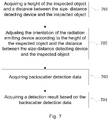
- Fig.7 is a flowchart showing the security inspection method according to an embodiment of the invention.
- the size-distance detecting device acquires a height of the inspected object and a distance between the inspected object and the size-distance detecting device.
- the orientation of the radiation emitting device is adjusted according to the height of the inspected object and the distance between the inspected object and the size-distance detecting device. For example, when it is detected that the inspected object is high, reduce the height of the radiation emitting device ,and emit ray beams at an angle horizontally upwards; when it is detected that the inspected object is low, raise the height of the radiation emitting device, and emit ray beams at an angle horizontally downwards; when it is detected that the distance between the inspected object and the size-distance detecting device is fare, the decrease the distance between the radiation emitting device and the size-distance detecting device; when it is detected that the distance between the inspected object and the size-distance detecting device is near, increase the distance between the radiation emitting device and the size-distance detecting device.
- step 703 the backscatter detection data is acquired by using a back-scatter detector.
- step 704 a detection result is acquired based on the backscatter detection data.
- Fig.8 is a flowchart showing the security inspection method according to another embodiment of the invention.
- step 801 a height of the inspected object and a distance between the inspected object and the size-distance detecting device are acquired by using a size-distance detecting device.
- step 802 the orientation of the radiation emitting device is adjusted according to the height of the inspected object, and the distance between the inspected object and the size-distance detecting device.
- an angle of the back-scatter detector is adjusted according to the orientation of the radiation emitting device.
- the back-scatter detector is adjusted to an angle of the back-scatter detector 2shown by the dotted lines in a lower portion; when the radiation emitting device 1 is adjusted to the orientation of the radiation emitting device 1 shown by the dotted lines on the bottom of the figure, the back-scatter detector is adjusted to an angle of the back-scatter detector 2shown by the dotted lines in a upper portion; when the radiation emitting device 1 is in the position shown by the middle solid lines, the back-scatter detector is adjusted to an angle of the back-scatter detector 2 drawn by the middle solid lines.
- step 804 backscatter detection data is acquired by using a back-scatter detector.
- step 805 a detection result is acquired based on the backscatter detection data.
- a plurality of sensors may be utilized for determining a height of the inspected object by judging a height of an obstacle in front of the sensors.
- the size-distance detecting device has a column of sensors that can judge a height of the inspected object by judging that in front of which sensors there are obstacles. Such a method can determine the size of the inspected object by existed and easily assembled equipments, and thus has a low cost and is easily promoted and applied.
- a camera close to the sensor can be utilized for shooting in the direction of the inspected object, thus we can acquire a video image of the inspected object. And then a distance between the inspected object and the camera can be acquired according to the video image and the height of the inspected object determined by the sensor. As shown in Fig.9 .
- a height H of the inspected object is determined by judging a height of an obstacle in front of the sensor.
- step 902 a camera which is located on a perpendicular bisector of the security inspection apparatus and the inspected object in horizontal plane, shoots in the direction of the perpendicular bisector between the security inspection apparatus and the inspected object.
- step 903 an image height h of the inspected object and an image distance d between the inspected object and the size-distance detecting device are acquired according to the video image.
- step 904 the actual distance between the inspected object and the size-distance detecting device is D.
- a plurality of gears can be set according to actual size requirements of the inspected object, each gear for detecting inspected objects in a corresponding predetermined size range.
- a corresponding gear can be determined from the size of the inspected object determined by the size-distance detecting device, and then the radiation emitting device is adjusted to the position and angle of the corresponding gear.
- the distance between the inspected object and the size-distance detecting device is D; determine the ideal distance D1 between the inspected object and the radiation emitting device based on the size of the inspected object ; and the ideal distance between the radiation emitting device and the size-distance detecting device is D1-D.
- a gear in which the distance between the radiation emitting device and the size-distance detecting device is closest to D1-D will be selected, and the radiation emitting device will be adjusted to the position and angle of the corresponding gear.
- a security inspection apparatus can adjust the distance between the radiation emitting device and the size-distance detecting device according to the distance between the inspected object and the size-distance detecting device, realize the adjustment of the distance between the radiation emitting device and the inspected object, which on one hand, optimizes the detection effect, and on the other hand, reduces the requirement on the distance between the security inspection apparatus and the inspected object, such that the security inspection process is more convenient and feasible.
- an ideal height of the radiation emitting device and an ideal emission angle can be calculated based on a predetermined strategy, and the radiation emitting device can be adjusted to be in the ideal height, and emit rays with the ideal angle.
- a security inspection apparatus can adjust the radiation emitting device according to the ideal height and angle to detect the inspected object, thereby obtaining more accurate detection data and reaching a better detection effect.
- the ideal distance between the radiation emitting device and the inspected object can be calculated according to the ideal detection distance D1 between the radiation emitting device and the inspected object, and the distance D between the size-distance detecting device and the inspected object that, the ideal distance between the radiation detecting device and the size-distance detecting device is D1-D, thereby adjusting the distance between the radiation emitting device and the size-distance detecting device as the ideal distance.
- Fig.10 is a flowchart showing the security inspection method according to a further embodiment of the invention.
- a step 1001 the inspected object passes through the detection area of the security inspection apparatus.
- the size-distance detecting device of the security inspection apparatus detects the size of the inspected object, and a distance between the inspected object and the size-distance detecting device.
- the security inspection apparatus adjusts the position and angle of the radiation emitting device and the angle of the back-scatter detector according to the size of the inspected object, and the distance between the inspected object and the size-distance detecting device.
- the radiation emitting device emits flying point rays to the inspected object and the back-scatter detector receives the backscatter rays.
- detection data is acquired through the back-scatter detector.
- the detection image can be displayed according to the backscatter data to determine the detection result.
- Fig.11 is a flowchart of the security inspection method according to a further again embodiment of the invention.
- the detection data can be acquired in the way shown in the embodiment of Fig.10 .
- a suspicious area is determined from the acquired detection data.
- the suspicious area may comprise an unidentifiable area, a detection dead angle or a suspicious contraband object area.
- the operator can pay attention to the detection of the suspicious area.
- the operator adjusts the position and angle of the radiation emitting device and the angle of the back-scatter detector, to perform multiple scans on the suspicious area.
- a step 1104 by performing multiple scans on the suspicious area, multiple detection data is acquired.
- a step 1105 determine the detection result from the multiple detection data.
Landscapes
- Physics & Mathematics (AREA)
- General Physics & Mathematics (AREA)
- Life Sciences & Earth Sciences (AREA)
- Chemical & Material Sciences (AREA)
- Geophysics (AREA)
- General Life Sciences & Earth Sciences (AREA)
- High Energy & Nuclear Physics (AREA)
- Pathology (AREA)
- General Health & Medical Sciences (AREA)
- Crystallography & Structural Chemistry (AREA)
- Biochemistry (AREA)
- Immunology (AREA)
- Analytical Chemistry (AREA)
- Health & Medical Sciences (AREA)
- Analysing Materials By The Use Of Radiation (AREA)
- Geophysics And Detection Of Objects (AREA)
- Length Measuring Devices By Optical Means (AREA)
- Burglar Alarm Systems (AREA)
Abstract
Description
- The present invention relates to the technical field of radiation, and particularly a security inspection apparatus and method.
- X-ray backscatter imaging is getting more and more important in security inspection because it can well detect the material of an object with a low atomic number. An embodiment is as follows: a flywheel rotates about a radiation source to form a pencil beam, and the pencil beam interacts with an inspected object to form a flying spot through Compton scattering. A back-scatter detector collects X-ray backscatter rays of the flying spot at any time, and after processing, information of the material is obtained, i.e., a backscatter image is formed. After continuous scanning, internal information of the whole object inspected can be processed and obtained, and objects with a lower atomic number, e.g., contraband goods such as explosives, drugs, hidden in concealed locations such as vehicle door interlayer, vehicle bottom, could be highlighted.
- The existing flying point device operates as follows: a radiation source generates fan-shaped X-rays that pass through a rotating shield with multiple collimating holes to continuously generate a pencil beam for achieving a first dimensional scanning, and achieving a second-dimensional scanning by rotating or translating the rays to scan sectors.
- However, if objects with different sizes are lined up, and the existing backscatter device is stationary in its scanning angle and scanning position including vertical and horizontal position, the view angle of the image is possibly bad, such that occlusion or overlap is formed between internal structures of the inspected objects, and suspicious goods cannot be highly identified under this angle.
- An object of this invention is to provide a security inspection approach that can flexibly adjust the position of the ray source according to the condition of the inspected object.
- According to an aspect of the invention, a security inspection apparatus is provided, comprising: a radiation emitting device, a back-scatter detector located between the radiation emitting device and an inspected object, a size-distance detecting device located between the radiation emitting device and the inspected object, for detecting a size of the inspected object and/or a distance from the inspected object, and an orientation adjusting device for adjusting a orientation of the radiation emitting device according to the size of the inspected object and/or the distance between the inspected object and the size-distance detecting device.
- Further, the orientation adjusting device further adjusts an angle of the back-scatter detector according to the orientation of the radiation emitting device.
- Further, the size-distance detecting device comprises a plurality of sensors for determining a height of the inspected object by judging a height of an obstacle in front of the sensors.
- Further, the size-distance detecting device further comprises: a camera located on a perpendicular bisector of the security inspection apparatus and the inspected object in a horizontal plane, and shoots in the direction of the perpendicular bisector; a calculating device acquires an image height of the inspected object and an image distance between the inspected object and the size-distance detecting device in a video image shot by the camera, and determines a distance between the inspected object and the size-distance detecting device from a ratio of the image distance to the image height and the height of the inspected object detected by the sensor.
- Further, the orientation adjusting device adjusts a height and an emission angle of the radiation emitting device based on a predetermined gear, according to the height of the inspected object and/or the distance between the inspected object and the size-distance detecting device.
- Further, the orientation adjusting device adjusts a distance between the radiation emitting device and the inspected object based on a predetermined gear, according to the height of the inspected object and/or the distance between the inspected object and the size-distance detecting device.
- Further, the orientation adjusting device determines an ideal height and an ideal emission angle of the radiation emitting device based on a predetermined strategy, from the height of the inspected object and/or the distance between the inspected object and the size-distance detecting device, and adjusts the height and the emission angle of the radiation emitting device according to the ideal height and the ideal emission angle.
- Further, the orientation adjusting device determines an ideal distance between the radiation emitting device and the inspected object based on a predetermined strategy, from the height of the inspected object and/or the distance between the inspected object and the size-distance detecting device, and adjusts the distance between the radiation emitting device and the inspected object according to the ideal distance.
- Further, the orientation adjusting device adjusts an angle of the back-scatter detector based on a predetermined gear, according to the height and the emission angle of the radiation emitting device, or determines an ideal angle of the back-scatter detector from the height and the emission angle of the radiation emitting device, and adjusts the angle of the back-scatter detector according to the ideal angle.
- Further, the back-scatter detector is arc-shaped.
- Further, the radiation emitting device comprises: a ray source located in a center of the radiation emitting device; and a spatial modulator located between the radiation source and the back-scatter detector, comprising a fixed shielding plate and a rotating shielding plate which located between the inspected object and the fixed shielding plate, and comprises more than one hole.
- Further, the security inspection apparatus further comprises a transportation facility for carrying and moving the security inspection apparatus.
- Further, the security inspection apparatus further comprises: a control device for manually controlling the orientation adjusting device to perform the adjusting operation according to detection needs.
- Further, the security inspection apparatus further comprises a processor for receiving detection signals from the back-scatter detector.
- Such a security inspection apparatus can detect size and position information of the inspected object, and automatically adjust the orientation of the radiation emitting device according to the size and position of the inspected object, thereby reducing or avoiding detection dead angles, and improving accuracy of the detection.
- According to another aspect of the invention, a security inspection method is provided, comprising: acquiring a height of an inspected object and a distance between the inspected object and a size-distance detecting device; adjusting an orientation of a radiation emitting device according to the height of the inspected object and the distance between the inspected object and the size-distance detecting device; acquiring backscatter detection data by a back-scatter detector; and acquiring a detection result based on the backscatter detection data.
- Further, the security inspection method further comprise: adjusting an angle of the back-scatter detector according to the orientation of the radiation emitting device.
- Further, acquiring a height of an inspected object comprises: the height of the inspected object is acquired by using a plurality of sensors acquire to judge a height of an obstacle in front of the sensors.
- Further, acquiring a distance between the inspected object and the size-distance detecting device comprises: a video image is acquired by using a camera located on a perpendicular bisector of the security inspection apparatus and the inspected object in a horizontal plane, and shooting in the direction of the perpendicular bisector; acquiring an image height of the inspected object and an image distance between the inspected object and the size-distance detecting device in the video image, and determining a distance between the inspected object and the size-distance detecting device from a ratio of the image distance to the image height and the height of the inspected object.
- Further, adjusting the orientation of the radiation emitting device according to the height of the inspected object and the distance between the inspected object and the size-distance detecting device further comprises: adjusting a height and a emission angle of the radiation emitting device based on a predetermined gear, according to the height of the inspected object and/or the distance between the inspected object and the size-distance detecting device.
- Further, adjusting the orientation of the radiation emitting device according to the height of the inspected object and the distance between the inspected object and the size-distance detecting device further comprises: adjusting the distance between the radiation emitting device and the inspected object based on a predetermined gear, according to the height of the inspected object and the distance between the inspected object and the size-distance detecting device.
- Further, adjusting the orientation of the radiation emitting device according to the height of the inspected object and the distance between the inspected object and a size-distance detecting device further comprises: determining an ideal height and an ideal emission angle of the radiation emitting device based on a predetermined strategy, from the height of the inspected object and/or the distance between the inspected object and the size-distance detecting device, and adjusting the height and the emission angle of the radiation emitting device according to the ideal height and the ideal emission angle.
- Further, adjusting the orientation of the radiation emitting device according to the height of the inspected object and the distance between the inspected object and a size-distance detecting device further comprises: determining an ideal distance between the radiation emitting device and the inspected object using a predetermined strategy from the height of the inspected object and/or the distance between the inspected object and a size-distance detecting device, and adjusting the distance between the radiation emitting device and the size-distance detecting device according to the ideal distance.
- Further, adjusting an angle of the back-scatter detector according to the orientation of the radiation emitting device further comprises: adjusting the angle of the back-scatter detector based on a predetermined gear, according to the height and the emission angle of the radiation emitting device.
- Further, adjusting an angle of the back-scatter detector according to the orientation of the radiation emitting device further comprises: determining an ideal angle of the back-scatter detector from the height and the emission angle of the radiation emitting device, and adjusting the angle of the back-scatter detector according to the ideal angle.
- Further, the security inspection method further comprise: manually adjusting the orientation of the radiation emitting device and/or the angle of the back-scatter detector according to detection needs.
- Further, manually adjusting the orientation of the radiation emitting device and/or the angle of the back-scatter detector according to detection needs comprises: manually adjusting the orientation of the radiation emitting device and/or the angle of the back-scatter detector for many times according to detection needs; acquiring backscatter detection data by a back-scatter detector comprises acquiring backscatter detection data after each time adjusting the orientation of the radiation emitting device and the angle of the back-scatter detector; and acquiring a detection result based on the backscatter detection data comprises: making a comprehensive analysis of the backscatter detection data acquired each time to determine the detection result.
- In this way, we can detect size and position information of the inspected object, and automatically adjust the orientation of the radiation emitting device according to the size and position of the inspected object, thereby reducing or avoiding detection dead angles, and improving accuracy of the detection.
- The accompanying drawings illustrated herein provide further understandings to the invention and constitute a portion of the present application. The illustrative embodiments of the invention and their descriptions are used for explaining the invention and do not constitute improper definitions to the invention.
-
Fig.1 is a schematic diagram of the security inspection apparatus according to one embodiment of this invention. -
Fig.2 is a schematic diagram of the security inspection apparatus according to another embodiment of this invention. -
Fig.3 is a schematic diagram of the radiation emitting device of the security inspection apparatus according to one embodiment of this invention. -
Fig.4 is a schematic diagram showing the security inspection apparatus determines a distance between the inspected object and the size-distance detecting device from one embodiment of this invention. -
Fig.5 is a schematic diagram of the security inspection apparatus according to a further embodiment of this invention. -
Fig.6 is a schematic diagram of the security inspection apparatus according to a further again embodiment of this invention. -
Fig.7 is a flowchart showing the security inspection method according to an embodiment of this invention. -
Fig.8 is a flowchart showing the security inspection method according to another embodiment of this invention. -
Fig.9 is a flowchart showing one embodiment for determining a height of the inspected object and a distance between the size- distance detecting device and the inspected object according to this invention. -
Fig.10 is a flowchart showing the security inspection method according to a further embodiment of this invention. -
Fig.11 is a flowchart showing the security inspection method according to a further again embodiment of this invention. - The present invention will be further illustrated below in details in conjunction with the accompanying drawings with exemplary embodiments. It is to be understood that the following Detailed Description is merely exemplary, rather than to limiting the present invention inappropriately.
- The existing X-ray inspection apparatus cannot make real-time adjustments according to the size and position of the inspected object since components thereof have relatively fixed positions, which possibly will result in a poor effect of the backscatter scan image: for example, if the ray emission position is fixed, the view angle of the output image perhaps will be bad, and internal structures form occlusion or overlap, and suspicious objects cannot be well identified.
-
Fig.1 is a schematic diagram of the security inspection apparatus according to one embodiment of this invention. Theradiation emitting device 1 is capable of emittingrays 3 to an inspectedobject 4. The back-scatter detector is capable of acquiring backscatter rays and generating backscatter data. The security inspection apparatus further comprises a size-distance detecting device 5 located between theradiation emitting device 1 and the inspected object 4.The size-distance detecting device 5 is capable of detecting a size of the inspectedobject 4 and a distance from the inspectedobject 4. The orientation adjustingdevice 6 is capable of adjusting the orientation of the radiation emitting device according to the size of the inspectedobject 4 and the distance between the inspectedobject 4 and the size-distance detecting device 5. As shown by the dotted lines inFig.1 , the orientation adjusting device can adjust height, emission angle, and etc. of the radiation emitting device. For example, when it is detected that the inspected object is high, reduce the height of the radiation emitting device, and emit ray beams at an angle horizontally upwards; when it is detected that the inspected object is low, raise the height of the radiation emitting device, and emit ray beams at an angle horizontally downwards; when it is detected that the distance between the inspected object and the size-distance detecting device is fare, the decrease the distance between the radiation emitting device and the size-distance detecting device; when it is detected that the distance between the inspected object and the size-distance detecting device is near, increase the distance between the radiation emitting device and the size-distance detecting device. - Such a security inspection apparatus can detect size and position information of the inspected object, and automatically adjust the orientation of the radiation emitting device according to the size and position of the inspected object, thereby reducing or avoiding detection dead angles, and improving accuracy of the detection.
- In an embodiment, the back-scatter detector may be arc-shaped, and such a security inspection apparatus can better receive backscatter rays to thereby generate better backscatter data.
- In one embodiment, the orientation adjusting device can adjust the angle of the back-scatter detector according to the orientation of the radiation emitting device. As shown in
Fig.2 , when theradiation emitting device 1 is adjusted to the orientation of theradiation emitting device 1 shown by the dotted lines on top of the figure, the back-scatter detector is adjusted to an angle of the back-scatter detector 2shown by the dotted lines in a lower portion; when theradiation emitting device 1 is adjusted to the orientation of theradiation emitting device 1 shown by the dotted lines on the bottom of the figure, the back-scatter detector is adjusted to an angle of the back-scatter detector 2shown by the dotted lines in a upper portion; when theradiation emitting device 1 is in the position shown by the middle solid lines, the back-scatter detector is adjusted to an angle of the back-scatter detector 2 drawn by the middle solid lines. - Such a security inspection apparatus can adjust the orientation of the radiation emitting device according to the position and size of the inspected object, and can adjust the angle of the back-scatter detector according to the orientation of the radiation emitting device, thereby better receiving backscatter rays to acquire more accurate and complete backscatter data.
- In one embodiment, a schematic diagram of the
radiation emitting device 1 of the security inspection apparatus is shown inFig.3 . Aray source 11 can emitsX-rays 3; a fixedshielding plate 12 is capable of restricting therays 3 to be emitted in a fixed direction with a fixed angle; arotatingshield13 has at least onehole 14. The rotatingshield 13 rotates continuously, and when thehole 14 reaches the emission range of therays 3 restricted by the fixedshielding plate 12, the rays are emitted through thehole 14 to form a flying spot beam. - In such a security inspection apparatus, the radiation emitting device can emit rays with a predetermined frequency and angle, which facilitates adjustment and control as needed.
- In one embodiment, the size-distance detecting device comprises a plurality of sensors for determining a height of the inspected object by judging a height of an obstacle in front of the sensors. In one embodiment, the size-distance detecting device has a column of sensors that can judge a height of the inspected object by judging that in front of which sensors there are obstacles.
- Such a security inspection apparatus can determine the size of the inspected object by existed and easily assembled equipments, and thus has a low cost and is easily promoted and applied.
- In an embodiment, there is a camera located on a perpendicular bisector of the security inspection apparatus and the inspected object in horizontal plane, which shoots in the direction of the perpendicular bisector, and thus can acquire a video image of the inspected object. An embodiment of the view angle of the video image is shown in
Fig.4 . Based on the video image, an image distance d between the inspected object and the size-distance detecting device, and an image height h of the inspected object can be acquired. Since the sensor can be utilized for acquiring an actual height H of the inspected object, as shown inFig.4 , the object on the left side is the security inspection apparatus, and the object on the right side is the inspected object. The actual distance between the inspected object and the size-distance detecting device is D. The actual distance D between the inspected object and the camera is determined from the formula:
- It can be regard as the distance between the inspected object and the size-distance detecting device.
- Such a security inspection apparatus can acquire the size of the inspected object, and the distance from the size-distance detecting device by cleverly using the sensors and the camera in combination with data analysis, thereby providing data for adjusting the orientation of the radiation emitting device and the angle of the back-scatter detector.
- In one embodiment, there is a 3D camera in the vicinity of the sensor, which can directly acquire the distance information between the inspected object and the camera. Such an apparatus has a simpler construction, and response speed of the security inspection apparatus is increased since operations of calculation are omitted.
- In one embodiment, a plurality of gears can be set according to actual size requirements of the inspected object, each gear for detecting inspected objects in a corresponding predetermined size range. In an embodiment, the inspected object may be a vehicle. Since the size of vehicles is relatively fixed, and can be classified as three kinds, namely full size vehicle, midsize vehicle and compact size vehicle, the gears of the
radiation emitting device 1 and the back-scatter detector 2 can be set according to the vehicle's size. As shown inFig.5 , three gears a, b, c can be set, wherein the gear b is a reference gear in which the radiation emitting device is in the middle and shoots in the horizontal direction; the radiation emitting device at the gear a is located about 60cm above the reference gear position and emits rays horizontally downwards at a 30 degree angle; the radiation emitting device at the gear c is located about 60 cm under the reference gear position, and emits rays horizontally upwards at a 30 degree angle. - A compact size vehicle can use the gear a, a midsize vehicle can use the gear b, and a full size vehicle can use the gear c. The position and angle of the
radiation emitting device 1 and the back-scatter detector 2 at respective gears can be determined from the size of the inspected vehicle. Such a security inspection apparatus can adjust the orientation of the radiation emitting device and the angle of the back-scatter detector according to the predetermined gears, and thus has advantages such as lower requirement on the apparatus, faster response speed, and is easily promoted and applied. - In an embodiment, after acquiring the height of the inspected object, and the distance between the size-distance detecting device and the inspected object, an ideal height of the radiation emitting device and an ideal emission angle can be calculated based on a predetermined strategy, and the radiation emitting device can be adjusted to be in the ideal height, and emit rays with the ideal angle. Such a security inspection apparatus is adapted to the detection of various sizes of the inspected objects, and can adjust the radiation emitting device according to the ideal height and angle to detect the inspected object, thereby obtaining more accurate detection data and reaching a better detection effect.
- In an embodiment, a plurality of gears can also be set for the distance between the radiation emitting device and the size-distance detecting device to adjust the horizontal orientation of the radiation emitting device. Since viewed from the principle of back-scatter detection, the closer the radiation emitting device is to the inspected object, the better the effect is. However, since the radiation angle of the radiation emitting device is limited, the distance between the radiation emitting device and the inspected object should be closer under the premise that the radiation angle covers the area to be inspected, and this distance is the ideal detection distance between the radiation emitting device and the inspected object.
- If the ideal detection distance between the radiation emitting device and the inspected object is D1, and the distance between the size-distance detecting device and the inspected object is D, then the ideal distance between the radiation emitting device and the size-distance detecting device is D1-D, so a gear in which the distance between the radiation emitting device and the size-distance detecting device is closest to D1-D is selected, and the radiation emitting device is adjusted to the corresponding gear position. For example, three gears a, b, c are set for the distance between the radiation emitting device and the size-distance detecting device, the distance between the radiation emitting device and the size-distance detecting device is 45cm, 60cm, 75cmrespectively. According to the size of the inspected object, it is determined that the ideal distance between the inspected object and the radiation emitting device is 2m, and the distance between the inspected object and the size-distance detecting device is 1.5m, so it is needed to adjust the distance between the size-distance detecting device and the radiation emitting device to be 50cm, then the radiation emitting device is adjusted to be in the position of gear a.
- Such a security inspection apparatus can adjust the distance between the radiation emitting device and the size-distance detecting device according to the distance between the inspected object and the size-distance detecting device, realize the adjustment of the distance between the radiation emitting device and the inspected object, which on one hand, optimizes the detection effect, and on the other hand, reduces the requirement on the distance between the security inspection apparatus and the inspected object, such that the security inspection process is more convenient and feasible.
- In an embodiment, it can be calculated according to the ideal detection distance D1 between the radiation emitting device and the inspected object, and the distance D between the size-distance detecting device and the inspected object that, the ideal distance between the radiation detecting device and the size-distance detecting device is D1-D, thereby adjusting the distance between the radiation emitting device and the size-distance detecting device as the ideal distance. For example, it is determined according to the size of the inspected object that the ideal distance between the inspected object and the radiation emitting device is 2m, and the distance between the inspected object and the size-distance detecting device is 1.5m, so it is needed to adjust the distance between the radiation emitting device and the size-distance detecting device to be 50cm, and then the radiation emitting device is adjusted to be located at a distance of 50cm from the size-distance detecting device.
- Such a security inspection apparatus can adjust the orientation of the radiation emitting device according to the ideal distance between the radiation emitting device and the size-distance detecting device, which further optimizes the detection effect.
-
Fig.6 is a schematic diagram showing the security inspection apparatus according to a further again embodiment of the invention. The security inspection apparatus further comprises a transportation facility 7 for carrying and moving the security inspection apparatus, which has the following advantages: facilitating transportation and flexible scheduling directed to emergencies; occupying a smaller area; continuously detecting a plurality of inspected objects by moving the security inspection apparatus in case where the inspected objects are inconvenient to be moved; easy use and convenient promotion and application. - In one embodiment, the security inspection apparatus further comprises a processor for receiving detection signals from the back-scatter detector, generating backscatter detection images, analyzing the inspected object and generating the detection result. Such a security inspection apparatus can obtain the detection image and the detection result in real time, which improves the detection efficiency.
- In one embodiment, the security inspection apparatus further comprises a control device. An operator can manually adjust the position of the radiation detecting device and the angle of the back-scatter detector with the control device. By using such a security inspection apparatus, the operator can adjust the radiation detecting device and the back-scatter detector from multiple angles and positions according to detection needs, which is helpful to the identification of suspicious objects and improves accuracy of the detection.
-
Fig.7 is a flowchart showing the security inspection method according to an embodiment of the invention. - In
step 701, the size-distance detecting device acquires a height of the inspected object and a distance between the inspected object and the size-distance detecting device. - In
step 702, the orientation of the radiation emitting device is adjusted according to the height of the inspected object and the distance between the inspected object and the size-distance detecting device. For example, when it is detected that the inspected object is high, reduce the height of the radiation emitting device ,and emit ray beams at an angle horizontally upwards; when it is detected that the inspected object is low, raise the height of the radiation emitting device, and emit ray beams at an angle horizontally downwards; when it is detected that the distance between the inspected object and the size-distance detecting device is fare, the decrease the distance between the radiation emitting device and the size-distance detecting device; when it is detected that the distance between the inspected object and the size-distance detecting device is near, increase the distance between the radiation emitting device and the size-distance detecting device. - In
step 703, the backscatter detection data is acquired by using a back-scatter detector. - In
step 704, a detection result is acquired based on the backscatter detection data. - In this way, we can detect size and position information of the inspected object, and automatically adjust the orientation of the radiation emitting device according to the size and position of the inspected object, thereby reducing or avoiding detection dead angles, and improving accuracy of the detection.
-
Fig.8 is a flowchart showing the security inspection method according to another embodiment of the invention. - In
step 801, a height of the inspected object and a distance between the inspected object and the size-distance detecting device are acquired by using a size-distance detecting device. - In
step 802, the orientation of the radiation emitting device is adjusted according to the height of the inspected object, and the distance between the inspected object and the size-distance detecting device. - In
step 803, an angle of the back-scatter detector is adjusted according to the orientation of the radiation emitting device. As shown inFig.2 , when theradiation emitting device 1 is adjusted to the orientation of theradiation emitting device 1 shown by the dotted lines on top of the figure, the back-scatter detector is adjusted to an angle of the back-scatter detector 2shown by the dotted lines in a lower portion; when theradiation emitting device 1 is adjusted to the orientation of theradiation emitting device 1 shown by the dotted lines on the bottom of the figure, the back-scatter detector is adjusted to an angle of the back-scatter detector 2shown by the dotted lines in a upper portion; when theradiation emitting device 1 is in the position shown by the middle solid lines, the back-scatter detector is adjusted to an angle of the back-scatter detector 2 drawn by the middle solid lines. - In
step 804, backscatter detection data is acquired by using a back-scatter detector. - In
step 805, a detection result is acquired based on the backscatter detection data. - In this way, we can adjust the orientation of the radiation emitting device according to the position and size of the inspected object, and can adjust the angle of the back-scatter detector according to the orientation of the radiation emitting device, thereby better receiving backscatter rays to acquire more accurate and complete backscatter data.
- In one embodiment, a plurality of sensors may be utilized for determining a height of the inspected object by judging a height of an obstacle in front of the sensors. In one embodiment, the size-distance detecting device has a column of sensors that can judge a height of the inspected object by judging that in front of which sensors there are obstacles. Such a method can determine the size of the inspected object by existed and easily assembled equipments, and thus has a low cost and is easily promoted and applied.
- In an embodiment, a camera close to the sensor can be utilized for shooting in the direction of the inspected object, thus we can acquire a video image of the inspected object. And then a distance between the inspected object and the camera can be acquired according to the video image and the height of the inspected object determined by the sensor. As shown in
Fig.9 . - In
step 901, a height H of the inspected object is determined by judging a height of an obstacle in front of the sensor. - In
step 902, a camera which is located on a perpendicular bisector of the security inspection apparatus and the inspected object in horizontal plane, shoots in the direction of the perpendicular bisector between the security inspection apparatus and the inspected object. - In
step 903, an image height h of the inspected object and an image distance d between the inspected object and the size-distance detecting device are acquired according to the video image. - In
step 904, the actual distance between the inspected object and the size-distance detecting device is D. The actual distance between the inspected object and the size-distance detecting device is determined from the formula: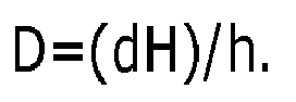
- In this way, we can acquire the size of the inspected object, and the distance from the size-distance detecting device by cleverly using the sensors and the camera in combination with data analysis, thereby providing data for adjusting the orientation of the radiation emitting device and the angle of the back-scatter detector.
- In one embodiment, a plurality of gears can be set according to actual size requirements of the inspected object, each gear for detecting inspected objects in a corresponding predetermined size range. A corresponding gear can be determined from the size of the inspected object determined by the size-distance detecting device, and then the radiation emitting device is adjusted to the position and angle of the corresponding gear.
- In an embodiment, the distance between the inspected object and the size-distance detecting device is D; determine the ideal distance D1 between the inspected object and the radiation emitting device based on the size of the inspected object ; and the ideal distance between the radiation emitting device and the size-distance detecting device is D1-D. A gear in which the distance between the radiation emitting device and the size-distance detecting device is closest to D1-D will be selected, and the radiation emitting device will be adjusted to the position and angle of the corresponding gear. In this way, a security inspection apparatus can adjust the distance between the radiation emitting device and the size-distance detecting device according to the distance between the inspected object and the size-distance detecting device, realize the adjustment of the distance between the radiation emitting device and the inspected object, which on one hand, optimizes the detection effect, and on the other hand, reduces the requirement on the distance between the security inspection apparatus and the inspected object, such that the security inspection process is more convenient and feasible.
- In an embodiment, after acquiring the height of the inspected object, and the distance between the size-distance detecting device and the inspected object, an ideal height of the radiation emitting device and an ideal emission angle can be calculated based on a predetermined strategy, and the radiation emitting device can be adjusted to be in the ideal height, and emit rays with the ideal angle. In this way, a security inspection apparatus can adjust the radiation emitting device according to the ideal height and angle to detect the inspected object, thereby obtaining more accurate detection data and reaching a better detection effect.
- In an embodiment, it can be calculated according to the ideal detection distance D1 between the radiation emitting device and the inspected object, and the distance D between the size-distance detecting device and the inspected object that, the ideal distance between the radiation detecting device and the size-distance detecting device is D1-D, thereby adjusting the distance between the radiation emitting device and the size-distance detecting device as the ideal distance.
- In this way, we can adjust the orientation of the radiation emitting device according to the ideal distance between the radiation emitting device and the size-distance detecting device, which further optimizes the detection effect.
-
Fig.10 is a flowchart showing the security inspection method according to a further embodiment of the invention. - In a
step 1001, the inspected object passes through the detection area of the security inspection apparatus. - In a
step 1002, the size-distance detecting device of the security inspection apparatus detects the size of the inspected object, and a distance between the inspected object and the size-distance detecting device. - In a
step 1003, the security inspection apparatus adjusts the position and angle of the radiation emitting device and the angle of the back-scatter detector according to the size of the inspected object, and the distance between the inspected object and the size-distance detecting device. The radiation emitting device emits flying point rays to the inspected object and the back-scatter detector receives the backscatter rays. - In a
step 1004, detection data is acquired through the back-scatter detector. The detection image can be displayed according to the backscatter data to determine the detection result. - In this way, we can adjust the orientation of the radiation emitting device and the angle of the back-scatter detector in real time according to the size and distance from the inspected object, and achieve fast detection of the inspected object; while optimizing the detecting effect, we can continuously scan a plurality of the inspected objects, which can increase throughput of the inspected objects, improve the detection speed and guarantee the detection efficiency.
-
Fig.11 is a flowchart of the security inspection method according to a further again embodiment of the invention. - In a
step 1101, the detection data can be acquired in the way shown in the embodiment ofFig.10 . - In a
step 1102, a suspicious area is determined from the acquired detection data. The suspicious area may comprise an unidentifiable area, a detection dead angle or a suspicious contraband object area. - In a
step 1103, the operator can pay attention to the detection of the suspicious area. In an embodiment, the operator adjusts the position and angle of the radiation emitting device and the angle of the back-scatter detector, to perform multiple scans on the suspicious area. - In a
step 1104, by performing multiple scans on the suspicious area, multiple detection data is acquired. - In a
step 1105, determine the detection result from the multiple detection data. - In this way, we can determine the suspicious area of the inspected object from the detection data of a single rapid detection, and then adjust the position and angle of the radiation emitting device and the angle of the back-scatter detector to pay attention to the detection of the suspicious area, thereby further optimizing the detection result.
- Although some particular embodiments of this invention have been illustrated in detail, those skilled in the art may understand that the above exemplary embodiments are merely illustrative, rather than to being any limitation to the scope of this invention, and various changes or modifications may be effected to above embodiments by those skilled in the art without departing from the scope and spirit of this invention as defined in the appended claims.
Claims (15)
- A security inspection apparatus comprising:a radiation emitting device,a back-scatter detector located between the radiation emitting device and an inspected object,a size-distance detecting device located between the radiation emitting device and the inspected object, for detecting a size of the inspected object and/or a distance from the inspected object, andan orientation adjusting device for adjusting a orientation of the radiation emitting device according to the size of the inspected object and/or the distance between the inspected object and the size-distance detecting device.
- The apparatus according to Claim 1, wherein the orientation adjusting device further adjusts an angle of the back-scatter detector according to the orientation of the radiation emitting device.
- The apparatus according to Claim 1, wherein the size-distance detecting device comprises a plurality of sensors for determining a height of the inspected object by judging a height of an obstacle in front of the sensors.
- The apparatus according to Claim 3, wherein the size-distance detecting device further comprises
a camera located on a perpendicular bisector of the security inspection apparatus and the inspected object in a horizontal plane, and shoots in the direction of the perpendicular bisector;
a calculating device acquires an image height of the inspected object and an image distance between the inspected object and the size-distance detecting device in a video image shot by the camera, and determines a distance between the inspected object and the size-distance detecting device from a ratio of the image distance to the image height and the height of the inspected object detected by the sensor. - The apparatus according to Claim 1, wherein
the orientation adjusting device adjusts a height and an emission angle of the radiation emitting device based on a predetermined gear, according to the height of the inspected object and/or the distance between the inspected object and the size-distance detecting device;
the orientation adjusting device adjusts a distance between the radiation emitting device and the inspected object based on a predetermined gear, according to the height of the inspected object and/or the distance between the inspected object and the size-distance detecting device;
the orientation adjusting device determines an ideal height and an ideal emission angle of the radiation emitting device based on a predetermined strategy, from the height of the inspected object and/or the distance between the inspected object and the size-distance detecting device, and adjusts the height and the emission angle of the radiation emitting device according to the ideal height and the ideal emission angle; and/or
the orientation adjusting device determines an ideal distance between the radiation emitting device and the inspected object based on a predetermined strategy, from the height of the inspected object and/or the distance between the inspected object and the size-distance detecting device, and adjusts the distance between the radiation emitting device and the inspected object according to the ideal distance. - The apparatus according to Claim 2, wherein
the orientation adjusting device adjusts an angle of the back-scatter detector based on a predetermined gear, according to the height and the emission angle of the radiation emitting device;
the orientation adjusting device determines an ideal angle of the back-scatter detector from the height and the emission angle of the radiation emitting device, and adjusts the angle of the back-scatter detector according to the ideal angle; and/or
the back-scatter detector is arc-shaped. - The apparatus according to Claim 1, wherein
the radiation emitting device comprises:a ray source located in a center of the radiation emitting device; anda spatial modulator located between the radiation source and the back-scatter detector, comprising a fixed shielding plate and a rotating shielding plate which located between the inspected object and the fixed shielding plate, and comprises more than one hole;and/or,
the security inspection apparatus further comprisinga transportation facility for carrying and moving the security inspection apparatus;a control device for manually controlling the orientation adjusting device to perform the adjusting operation according to detection needs; and/ora processor for receiving detection signals from the back-scatter detector. - A security inspection method comprising:acquiring a height of an inspected object and a distance between the inspected object and a size-distance detecting device;adjusting an orientation of a radiation emitting device according to the height of the inspected object and the distance between the inspected object and the size-distance detecting device;acquiring backscatter detection data by a back-scatter detector; andacquiring a detection result based on the backscatter detection data.
- The method according to Claim 8, further comprising:adjusting an angle of the back-scatter detector according to the orientation of the radiation emitting device.
- The method according to Claim 8, wherein acquiring a height of an inspected object comprises:the height of the inspected object is acquired by using a plurality of sensors acquire to judge a height of an obstacle in front of the sensors.
- The method according to Claim 10, wherein acquiring a distance between the inspected object and the size-distance detecting device comprises:a video image is acquired by using a camera located on a perpendicular bisector of the security inspection apparatus and the inspected object in a horizontal plane, and shooting in the direction of the perpendicular bisector;acquiring an image height of the inspected object and an image distance between the inspected object and the size-distance detecting device in the video image, anddetermining a distance between the inspected object and the size-distance detecting device from a ratio of the image distance to the image height and the height of the inspected object.
- The method according to Claim 8, wherein adjusting the orientation of the radiation emitting device according to the height of the inspected object and the distance between the inspected object and the size-distance detecting device further comprises:adjusting a height and a emission angle of the radiation emitting device based on a predetermined gear, according to the height of the inspected object and/or the distance between the inspected object and the size-distance detecting device; and/oradjusting the distance between the radiation emitting device and the inspected object based on a predetermined gear, according to the height of the inspected object and the distance between the inspected object and the size-distance detecting device;and/orwherein adjusting the orientation of the radiation emitting device according to the height of the inspected object and the distance between the inspected object and a size-distance detecting device further comprises:determining an ideal height and an ideal emission angle of the radiation emitting device based on a predetermined strategy, from the height of the inspected object and/or the distance between the inspected object and the size-distance detecting device, and adjusting the height and the emission angle of the radiation emitting device according to the ideal height and the ideal emission angle; and/ordetermining an ideal distance between the radiation emitting device and the inspected object using a predetermined strategy from the height of the inspected object and/or the distance between the inspected object and a size-distance detecting device, and adjusting the distance between the radiation emitting device and the size-distance detecting device according to the ideal distance.
- The method according to Claim 9, wherein adjusting an angle of the back-scatter detector according to the orientation of the radiation emitting device further comprises:adjusting the angle of the back-scatter detector based on a predetermined gear, according to the height and the emission angle of the radiation emitting device; ordetermining an ideal angle of the back-scatter detector from the height and the emission angle of the radiation emitting device, and adjusting the angle of the back-scatter detector according to the ideal angle.
- The method according to Claim 8, further comprising:manually adjusting the orientation of the radiation emitting device and/or the angle of the back-scatter detector according to detection needs.
- The method according to Claim 14, wherein manually adjusting the orientation of the radiation emitting device and/or the angle of the back-scatter detector according to detection needs comprises: manually adjusting the orientation of the radiation emitting device and/or the angle of the back-scatter detector for many times according to detection needs;
acquiring backscatter detection data by a back-scatter detector comprises acquiring backscatter detection data after each time adjusting the orientation of the radiation emitting device and the angle of the back-scatter detector; and
acquiring a detection result based on the backscatter detection data comprises: making a comprehensive analysis of the backscatter detection data acquired each time to determine the detection result.
Applications Claiming Priority (1)
| Application Number | Priority Date | Filing Date | Title |
|---|---|---|---|
| CN201610634086.2A CN106093089B (en) | 2016-08-05 | 2016-08-05 | Rays safety detection apparatus and method |
Publications (2)
| Publication Number | Publication Date |
|---|---|
| EP3279701A1 true EP3279701A1 (en) | 2018-02-07 |
| EP3279701B1 EP3279701B1 (en) | 2024-09-25 |
Family
ID=57454056
Family Applications (1)
| Application Number | Title | Priority Date | Filing Date |
|---|---|---|---|
| EP17173471.8A Active EP3279701B1 (en) | 2016-08-05 | 2017-05-30 | Security inspection apparatus and method |
Country Status (4)
| Country | Link |
|---|---|
| US (1) | US10585052B2 (en) |
| EP (1) | EP3279701B1 (en) |
| CN (1) | CN106093089B (en) |
| MY (1) | MY188950A (en) |
Families Citing this family (8)
| Publication number | Priority date | Publication date | Assignee | Title |
|---|---|---|---|---|
| CN106645224A (en) * | 2016-12-26 | 2017-05-10 | 同方威视技术股份有限公司 | Security inspection equipment and method |
| CN106526688A (en) * | 2016-12-28 | 2017-03-22 | 同方威视技术股份有限公司 | Back scattering inspection vehicle |
| CN108227027B (en) * | 2017-12-29 | 2020-12-01 | 同方威视技术股份有限公司 | Vehicle Backscatter Inspection System |
| CN108008458B (en) * | 2017-12-29 | 2020-09-08 | 同方威视技术股份有限公司 | Vehicle-mounted backscatter inspection system |
| CN108776322B (en) * | 2018-02-26 | 2020-10-16 | 张岚 | Ray source positioning method |
| US10859719B2 (en) * | 2018-12-13 | 2020-12-08 | The Boeing Company | Adjustable multifacet x-ray sensor array |
| CN112858358A (en) * | 2021-03-09 | 2021-05-28 | 公安部第一研究所 | Electrically-driven backscatter inspection vehicle |
| CN115372386A (en) * | 2022-07-25 | 2022-11-22 | 安徽承禹半导体材料科技有限公司 | Tellurium-zinc-cadmium crystal X-ray imaging system |
Citations (6)
| Publication number | Priority date | Publication date | Assignee | Title |
|---|---|---|---|---|
| US20040086078A1 (en) * | 2002-11-06 | 2004-05-06 | William Adams | X-ray backscatter mobile inspection van |
| US6967612B1 (en) * | 2004-10-22 | 2005-11-22 | Gorman John D | System and method for standoff detection of human carried explosives |
| WO2005121756A2 (en) * | 2004-06-03 | 2005-12-22 | Brondo Joseph H Jr | Mult-mode gamma beam detection and imaging system |
| EP1970700A1 (en) * | 2006-10-13 | 2008-09-17 | Nuctech Company Limited | A system and dodging method for imaging and detecting a moving object |
| US20140226789A1 (en) * | 2011-02-08 | 2014-08-14 | Joseph Bendahan | Covert Surveillance Using Multi-Modality Sensing |
| EP2963454A1 (en) * | 2014-07-04 | 2016-01-06 | Nuctech Company Limited | X-ray backscattering safety inspection system having a distributed-type x-ray source and method using the same |
Family Cites Families (7)
| Publication number | Priority date | Publication date | Assignee | Title |
|---|---|---|---|---|
| US5022062A (en) * | 1989-09-13 | 1991-06-04 | American Science And Engineering, Inc. | Automatic threat detection based on illumination by penetrating radiant energy using histogram processing |
| US7963695B2 (en) * | 2002-07-23 | 2011-06-21 | Rapiscan Systems, Inc. | Rotatable boom cargo scanning system |
| US8734013B2 (en) * | 2011-04-05 | 2014-05-27 | Satpal Singh | Small mobile x-ray scanning system |
| MX2013011843A (en) * | 2011-04-15 | 2013-11-01 | American Science & Eng Inc | Methods to perform backscatter inspection of complex targets in confined spaces. |
| CN104133251B (en) * | 2014-07-04 | 2017-08-25 | 清华大学 | Portable back scattering imaging rays safety detection apparatus and method |
| CN105301669B (en) * | 2015-12-04 | 2019-01-04 | 同方威视技术股份有限公司 | Rays safety detection apparatus and X-ray detection X method |
| CN205879830U (en) * | 2016-08-05 | 2017-01-11 | 同方威视技术股份有限公司 | Security installations |
-
2016
- 2016-08-05 CN CN201610634086.2A patent/CN106093089B/en active Active
-
2017
- 2017-05-25 MY MYPI2017701922A patent/MY188950A/en unknown
- 2017-05-30 EP EP17173471.8A patent/EP3279701B1/en active Active
- 2017-05-31 US US15/609,012 patent/US10585052B2/en active Active
Patent Citations (6)
| Publication number | Priority date | Publication date | Assignee | Title |
|---|---|---|---|---|
| US20040086078A1 (en) * | 2002-11-06 | 2004-05-06 | William Adams | X-ray backscatter mobile inspection van |
| WO2005121756A2 (en) * | 2004-06-03 | 2005-12-22 | Brondo Joseph H Jr | Mult-mode gamma beam detection and imaging system |
| US6967612B1 (en) * | 2004-10-22 | 2005-11-22 | Gorman John D | System and method for standoff detection of human carried explosives |
| EP1970700A1 (en) * | 2006-10-13 | 2008-09-17 | Nuctech Company Limited | A system and dodging method for imaging and detecting a moving object |
| US20140226789A1 (en) * | 2011-02-08 | 2014-08-14 | Joseph Bendahan | Covert Surveillance Using Multi-Modality Sensing |
| EP2963454A1 (en) * | 2014-07-04 | 2016-01-06 | Nuctech Company Limited | X-ray backscattering safety inspection system having a distributed-type x-ray source and method using the same |
Also Published As
| Publication number | Publication date |
|---|---|
| CN106093089A (en) | 2016-11-09 |
| US20180038808A1 (en) | 2018-02-08 |
| US10585052B2 (en) | 2020-03-10 |
| MY188950A (en) | 2022-01-14 |
| CN106093089B (en) | 2019-03-01 |
| EP3279701B1 (en) | 2024-09-25 |
Similar Documents
| Publication | Publication Date | Title |
|---|---|---|
| US10585052B2 (en) | Security inspection apparatus and method | |
| CN102713584B (en) | The system based on X ray of examinant's footwear is threatened for aviation safety | |
| US7263160B2 (en) | Method and device for examining an object | |
| US8199996B2 (en) | Systems and methods for improving directed people screening | |
| US7224772B2 (en) | Radiography by selective detection of scatter field velocity components | |
| US9915752B2 (en) | Inspection systems with two X-ray scanners in a first stage inspection system | |
| US7366282B2 (en) | Methods and systems for rapid detection of concealed objects using fluorescence | |
| EP1390780B1 (en) | X-ray inspection system | |
| EP3388868B1 (en) | Inspection devices and methods for inspecting a container | |
| EP2963454B1 (en) | X-ray backscattering safety inspection system having a distributed-type x-ray source and method using the same | |
| US20060245548A1 (en) | X-ray backscatter inspection with coincident optical beam | |
| CN203981903U (en) | X ray backscattered channel formula vehicle safe examination system based on distributed source of radiation | |
| CN205879830U (en) | Security installations | |
| CN120917339A (en) | Human body safety scanner | |
| US20130315469A1 (en) | Method for 3d inspection of an object using x-rays |
Legal Events
| Date | Code | Title | Description |
|---|---|---|---|
| PUAI | Public reference made under article 153(3) epc to a published international application that has entered the european phase |
Free format text: ORIGINAL CODE: 0009012 |
|
| STAA | Information on the status of an ep patent application or granted ep patent |
Free format text: STATUS: THE APPLICATION HAS BEEN PUBLISHED |
|
| AK | Designated contracting states |
Kind code of ref document: A1 Designated state(s): AL AT BE BG CH CY CZ DE DK EE ES FI FR GB GR HR HU IE IS IT LI LT LU LV MC MK MT NL NO PL PT RO RS SE SI SK SM TR |
|
| AX | Request for extension of the european patent |
Extension state: BA ME |
|
| STAA | Information on the status of an ep patent application or granted ep patent |
Free format text: STATUS: REQUEST FOR EXAMINATION WAS MADE |
|
| 17P | Request for examination filed |
Effective date: 20180806 |
|
| RBV | Designated contracting states (corrected) |
Designated state(s): AL AT BE BG CH CY CZ DE DK EE ES FI FR GB GR HR HU IE IS IT LI LT LU LV MC MK MT NL NO PL PT RO RS SE SI SK SM TR |
|
| STAA | Information on the status of an ep patent application or granted ep patent |
Free format text: STATUS: EXAMINATION IS IN PROGRESS |
|
| 17Q | First examination report despatched |
Effective date: 20190701 |
|
| GRAP | Despatch of communication of intention to grant a patent |
Free format text: ORIGINAL CODE: EPIDOSNIGR1 |
|
| STAA | Information on the status of an ep patent application or granted ep patent |
Free format text: STATUS: GRANT OF PATENT IS INTENDED |
|
| INTG | Intention to grant announced |
Effective date: 20240416 |
|
| RAP3 | Party data changed (applicant data changed or rights of an application transferred) |
Owner name: NUCTECH COMPANY LIMITED |
|
| GRAS | Grant fee paid |
Free format text: ORIGINAL CODE: EPIDOSNIGR3 |
|
| GRAA | (expected) grant |
Free format text: ORIGINAL CODE: 0009210 |
|
| STAA | Information on the status of an ep patent application or granted ep patent |
Free format text: STATUS: THE PATENT HAS BEEN GRANTED |
|
| AK | Designated contracting states |
Kind code of ref document: B1 Designated state(s): AL AT BE BG CH CY CZ DE DK EE ES FI FR GB GR HR HU IE IS IT LI LT LU LV MC MK MT NL NO PL PT RO RS SE SI SK SM TR |
|
| REG | Reference to a national code |
Ref country code: GB Ref legal event code: FG4D |
|
| REG | Reference to a national code |
Ref country code: CH Ref legal event code: EP |
|
| REG | Reference to a national code |
Ref country code: DE Ref legal event code: R096 Ref document number: 602017085022 Country of ref document: DE |
|
| REG | Reference to a national code |
Ref country code: IE Ref legal event code: FG4D |
|
| REG | Reference to a national code |
Ref country code: LT Ref legal event code: MG9D |
|
| PG25 | Lapsed in a contracting state [announced via postgrant information from national office to epo] |
Ref country code: NO Free format text: LAPSE BECAUSE OF FAILURE TO SUBMIT A TRANSLATION OF THE DESCRIPTION OR TO PAY THE FEE WITHIN THE PRESCRIBED TIME-LIMIT Effective date: 20241225 |
|
| PG25 | Lapsed in a contracting state [announced via postgrant information from national office to epo] |
Ref country code: GR Free format text: LAPSE BECAUSE OF FAILURE TO SUBMIT A TRANSLATION OF THE DESCRIPTION OR TO PAY THE FEE WITHIN THE PRESCRIBED TIME-LIMIT Effective date: 20241226 Ref country code: FI Free format text: LAPSE BECAUSE OF FAILURE TO SUBMIT A TRANSLATION OF THE DESCRIPTION OR TO PAY THE FEE WITHIN THE PRESCRIBED TIME-LIMIT Effective date: 20240925 |
|
| PG25 | Lapsed in a contracting state [announced via postgrant information from national office to epo] |
Ref country code: BG Free format text: LAPSE BECAUSE OF FAILURE TO SUBMIT A TRANSLATION OF THE DESCRIPTION OR TO PAY THE FEE WITHIN THE PRESCRIBED TIME-LIMIT Effective date: 20240925 |
|
| PG25 | Lapsed in a contracting state [announced via postgrant information from national office to epo] |
Ref country code: LV Free format text: LAPSE BECAUSE OF FAILURE TO SUBMIT A TRANSLATION OF THE DESCRIPTION OR TO PAY THE FEE WITHIN THE PRESCRIBED TIME-LIMIT Effective date: 20240925 |
|
| PG25 | Lapsed in a contracting state [announced via postgrant information from national office to epo] |
Ref country code: RS Free format text: LAPSE BECAUSE OF FAILURE TO SUBMIT A TRANSLATION OF THE DESCRIPTION OR TO PAY THE FEE WITHIN THE PRESCRIBED TIME-LIMIT Effective date: 20241225 |
|
| REG | Reference to a national code |
Ref country code: NL Ref legal event code: MP Effective date: 20240925 |
|
| PG25 | Lapsed in a contracting state [announced via postgrant information from national office to epo] |
Ref country code: RS Free format text: LAPSE BECAUSE OF FAILURE TO SUBMIT A TRANSLATION OF THE DESCRIPTION OR TO PAY THE FEE WITHIN THE PRESCRIBED TIME-LIMIT Effective date: 20241225 Ref country code: NO Free format text: LAPSE BECAUSE OF FAILURE TO SUBMIT A TRANSLATION OF THE DESCRIPTION OR TO PAY THE FEE WITHIN THE PRESCRIBED TIME-LIMIT Effective date: 20241225 Ref country code: LV Free format text: LAPSE BECAUSE OF FAILURE TO SUBMIT A TRANSLATION OF THE DESCRIPTION OR TO PAY THE FEE WITHIN THE PRESCRIBED TIME-LIMIT Effective date: 20240925 Ref country code: GR Free format text: LAPSE BECAUSE OF FAILURE TO SUBMIT A TRANSLATION OF THE DESCRIPTION OR TO PAY THE FEE WITHIN THE PRESCRIBED TIME-LIMIT Effective date: 20241226 Ref country code: FI Free format text: LAPSE BECAUSE OF FAILURE TO SUBMIT A TRANSLATION OF THE DESCRIPTION OR TO PAY THE FEE WITHIN THE PRESCRIBED TIME-LIMIT Effective date: 20240925 Ref country code: BG Free format text: LAPSE BECAUSE OF FAILURE TO SUBMIT A TRANSLATION OF THE DESCRIPTION OR TO PAY THE FEE WITHIN THE PRESCRIBED TIME-LIMIT Effective date: 20240925 |
|
| REG | Reference to a national code |
Ref country code: AT Ref legal event code: MK05 Ref document number: 1727098 Country of ref document: AT Kind code of ref document: T Effective date: 20240925 |
|
| PG25 | Lapsed in a contracting state [announced via postgrant information from national office to epo] |
Ref country code: NL Free format text: LAPSE BECAUSE OF FAILURE TO SUBMIT A TRANSLATION OF THE DESCRIPTION OR TO PAY THE FEE WITHIN THE PRESCRIBED TIME-LIMIT Effective date: 20240925 |
|
| PG25 | Lapsed in a contracting state [announced via postgrant information from national office to epo] |
Ref country code: IS Free format text: LAPSE BECAUSE OF FAILURE TO SUBMIT A TRANSLATION OF THE DESCRIPTION OR TO PAY THE FEE WITHIN THE PRESCRIBED TIME-LIMIT Effective date: 20250125 Ref country code: PT Free format text: LAPSE BECAUSE OF FAILURE TO SUBMIT A TRANSLATION OF THE DESCRIPTION OR TO PAY THE FEE WITHIN THE PRESCRIBED TIME-LIMIT Effective date: 20250127 |
|
| PG25 | Lapsed in a contracting state [announced via postgrant information from national office to epo] |
Ref country code: SM Free format text: LAPSE BECAUSE OF FAILURE TO SUBMIT A TRANSLATION OF THE DESCRIPTION OR TO PAY THE FEE WITHIN THE PRESCRIBED TIME-LIMIT Effective date: 20240925 Ref country code: RO Free format text: LAPSE BECAUSE OF FAILURE TO SUBMIT A TRANSLATION OF THE DESCRIPTION OR TO PAY THE FEE WITHIN THE PRESCRIBED TIME-LIMIT Effective date: 20240925 |
|
| PG25 | Lapsed in a contracting state [announced via postgrant information from national office to epo] |
Ref country code: ES Free format text: LAPSE BECAUSE OF FAILURE TO SUBMIT A TRANSLATION OF THE DESCRIPTION OR TO PAY THE FEE WITHIN THE PRESCRIBED TIME-LIMIT Effective date: 20240925 |
|
| PG25 | Lapsed in a contracting state [announced via postgrant information from national office to epo] |
Ref country code: EE Free format text: LAPSE BECAUSE OF FAILURE TO SUBMIT A TRANSLATION OF THE DESCRIPTION OR TO PAY THE FEE WITHIN THE PRESCRIBED TIME-LIMIT Effective date: 20240925 Ref country code: AT Free format text: LAPSE BECAUSE OF FAILURE TO SUBMIT A TRANSLATION OF THE DESCRIPTION OR TO PAY THE FEE WITHIN THE PRESCRIBED TIME-LIMIT Effective date: 20240925 |
|
| PG25 | Lapsed in a contracting state [announced via postgrant information from national office to epo] |
Ref country code: PL Free format text: LAPSE BECAUSE OF FAILURE TO SUBMIT A TRANSLATION OF THE DESCRIPTION OR TO PAY THE FEE WITHIN THE PRESCRIBED TIME-LIMIT Effective date: 20240925 Ref country code: CZ Free format text: LAPSE BECAUSE OF FAILURE TO SUBMIT A TRANSLATION OF THE DESCRIPTION OR TO PAY THE FEE WITHIN THE PRESCRIBED TIME-LIMIT Effective date: 20240925 |
|
| PG25 | Lapsed in a contracting state [announced via postgrant information from national office to epo] |
Ref country code: SK Free format text: LAPSE BECAUSE OF FAILURE TO SUBMIT A TRANSLATION OF THE DESCRIPTION OR TO PAY THE FEE WITHIN THE PRESCRIBED TIME-LIMIT Effective date: 20240925 Ref country code: IT Free format text: LAPSE BECAUSE OF FAILURE TO SUBMIT A TRANSLATION OF THE DESCRIPTION OR TO PAY THE FEE WITHIN THE PRESCRIBED TIME-LIMIT Effective date: 20240925 |
|
| REG | Reference to a national code |
Ref country code: DE Ref legal event code: R097 Ref document number: 602017085022 Country of ref document: DE |
|
| PG25 | Lapsed in a contracting state [announced via postgrant information from national office to epo] |
Ref country code: DK Free format text: LAPSE BECAUSE OF FAILURE TO SUBMIT A TRANSLATION OF THE DESCRIPTION OR TO PAY THE FEE WITHIN THE PRESCRIBED TIME-LIMIT Effective date: 20240925 |
|
| PLBE | No opposition filed within time limit |
Free format text: ORIGINAL CODE: 0009261 |
|
| STAA | Information on the status of an ep patent application or granted ep patent |
Free format text: STATUS: NO OPPOSITION FILED WITHIN TIME LIMIT |
|
| 26N | No opposition filed |
Effective date: 20250626 |
|
| PG25 | Lapsed in a contracting state [announced via postgrant information from national office to epo] |
Ref country code: SE Free format text: LAPSE BECAUSE OF FAILURE TO SUBMIT A TRANSLATION OF THE DESCRIPTION OR TO PAY THE FEE WITHIN THE PRESCRIBED TIME-LIMIT Effective date: 20240925 |
|
| REG | Reference to a national code |
Ref country code: DE Ref legal event code: R119 Ref document number: 602017085022 Country of ref document: DE |
|
| REG | Reference to a national code |
Ref country code: CH Ref legal event code: H13 Free format text: ST27 STATUS EVENT CODE: U-0-0-H10-H13 (AS PROVIDED BY THE NATIONAL OFFICE) Effective date: 20251223 |
|
| PG25 | Lapsed in a contracting state [announced via postgrant information from national office to epo] |
Ref country code: HR Free format text: LAPSE BECAUSE OF FAILURE TO SUBMIT A TRANSLATION OF THE DESCRIPTION OR TO PAY THE FEE WITHIN THE PRESCRIBED TIME-LIMIT Effective date: 20240925 Ref country code: LU Free format text: LAPSE BECAUSE OF NON-PAYMENT OF DUE FEES Effective date: 20250530 |
|
| PG25 | Lapsed in a contracting state [announced via postgrant information from national office to epo] |
Ref country code: CH Free format text: LAPSE BECAUSE OF NON-PAYMENT OF DUE FEES Effective date: 20250531 |
|
| GBPC | Gb: european patent ceased through non-payment of renewal fee |
Effective date: 20250530 |
|
| REG | Reference to a national code |
Ref country code: BE Ref legal event code: MM Effective date: 20250531 |
|
| PG25 | Lapsed in a contracting state [announced via postgrant information from national office to epo] |
Ref country code: MC Free format text: LAPSE BECAUSE OF FAILURE TO SUBMIT A TRANSLATION OF THE DESCRIPTION OR TO PAY THE FEE WITHIN THE PRESCRIBED TIME-LIMIT Effective date: 20240925 |
|
| PG25 | Lapsed in a contracting state [announced via postgrant information from national office to epo] |
Ref country code: GB Free format text: LAPSE BECAUSE OF NON-PAYMENT OF DUE FEES Effective date: 20250530 |
|
| PG25 | Lapsed in a contracting state [announced via postgrant information from national office to epo] |
Ref country code: IE Free format text: LAPSE BECAUSE OF NON-PAYMENT OF DUE FEES Effective date: 20250530 Ref country code: DE Free format text: LAPSE BECAUSE OF NON-PAYMENT OF DUE FEES Effective date: 20251202 |
|
| PG25 | Lapsed in a contracting state [announced via postgrant information from national office to epo] |
Ref country code: BE Free format text: LAPSE BECAUSE OF NON-PAYMENT OF DUE FEES Effective date: 20250531 |
|
| PG25 | Lapsed in a contracting state [announced via postgrant information from national office to epo] |
Ref country code: FR Free format text: LAPSE BECAUSE OF NON-PAYMENT OF DUE FEES Effective date: 20250531 |
|
| PG25 | Lapsed in a contracting state [announced via postgrant information from national office to epo] |
Ref country code: LT Free format text: LAPSE BECAUSE OF FAILURE TO SUBMIT A TRANSLATION OF THE DESCRIPTION OR TO PAY THE FEE WITHIN THE PRESCRIBED TIME-LIMIT Effective date: 20240925 |
|
| PG25 | Lapsed in a contracting state [announced via postgrant information from national office to epo] |
Ref country code: CY Free format text: LAPSE BECAUSE OF FAILURE TO SUBMIT A TRANSLATION OF THE DESCRIPTION OR TO PAY THE FEE WITHIN THE PRESCRIBED TIME-LIMIT Effective date: 20240925 |