EP3279678A1 - Gauging method for battery discharge-capacity corresponding to temperature and electronic device using the same - Google Patents
Gauging method for battery discharge-capacity corresponding to temperature and electronic device using the same Download PDFInfo
- Publication number
- EP3279678A1 EP3279678A1 EP16183045.0A EP16183045A EP3279678A1 EP 3279678 A1 EP3279678 A1 EP 3279678A1 EP 16183045 A EP16183045 A EP 16183045A EP 3279678 A1 EP3279678 A1 EP 3279678A1
- Authority
- EP
- European Patent Office
- Prior art keywords
- temperature
- battery
- capacity
- battery module
- battery discharge
- Prior art date
- Legal status (The legal status is an assumption and is not a legal conclusion. Google has not performed a legal analysis and makes no representation as to the accuracy of the status listed.)
- Granted
Links
Images


Classifications
-
- H—ELECTRICITY
- H01—ELECTRIC ELEMENTS
- H01M—PROCESSES OR MEANS, e.g. BATTERIES, FOR THE DIRECT CONVERSION OF CHEMICAL ENERGY INTO ELECTRICAL ENERGY
- H01M10/00—Secondary cells; Manufacture thereof
- H01M10/42—Methods or arrangements for servicing or maintenance of secondary cells or secondary half-cells
- H01M10/48—Accumulators combined with arrangements for measuring, testing or indicating the condition of cells, e.g. the level or density of the electrolyte
- H01M10/486—Accumulators combined with arrangements for measuring, testing or indicating the condition of cells, e.g. the level or density of the electrolyte for measuring temperature
-
- G—PHYSICS
- G01—MEASURING; TESTING
- G01R—MEASURING ELECTRIC VARIABLES; MEASURING MAGNETIC VARIABLES
- G01R31/00—Arrangements for testing electric properties; Arrangements for locating electric faults; Arrangements for electrical testing characterised by what is being tested not provided for elsewhere
- G01R31/36—Arrangements for testing, measuring or monitoring the electrical condition of accumulators or electric batteries, e.g. capacity or state of charge [SoC]
- G01R31/367—Software therefor, e.g. for battery testing using modelling or look-up tables
-
- G—PHYSICS
- G01—MEASURING; TESTING
- G01R—MEASURING ELECTRIC VARIABLES; MEASURING MAGNETIC VARIABLES
- G01R31/00—Arrangements for testing electric properties; Arrangements for locating electric faults; Arrangements for electrical testing characterised by what is being tested not provided for elsewhere
- G01R31/36—Arrangements for testing, measuring or monitoring the electrical condition of accumulators or electric batteries, e.g. capacity or state of charge [SoC]
- G01R31/374—Arrangements for testing, measuring or monitoring the electrical condition of accumulators or electric batteries, e.g. capacity or state of charge [SoC] with means for correcting the measurement for temperature or ageing
-
- G—PHYSICS
- G01—MEASURING; TESTING
- G01R—MEASURING ELECTRIC VARIABLES; MEASURING MAGNETIC VARIABLES
- G01R31/00—Arrangements for testing electric properties; Arrangements for locating electric faults; Arrangements for electrical testing characterised by what is being tested not provided for elsewhere
- G01R31/36—Arrangements for testing, measuring or monitoring the electrical condition of accumulators or electric batteries, e.g. capacity or state of charge [SoC]
- G01R31/382—Arrangements for monitoring battery or accumulator variables, e.g. SoC
- G01R31/3842—Arrangements for monitoring battery or accumulator variables, e.g. SoC combining voltage and current measurements
-
- G—PHYSICS
- G01—MEASURING; TESTING
- G01R—MEASURING ELECTRIC VARIABLES; MEASURING MAGNETIC VARIABLES
- G01R31/00—Arrangements for testing electric properties; Arrangements for locating electric faults; Arrangements for electrical testing characterised by what is being tested not provided for elsewhere
- G01R31/36—Arrangements for testing, measuring or monitoring the electrical condition of accumulators or electric batteries, e.g. capacity or state of charge [SoC]
- G01R31/389—Measuring internal impedance, internal conductance or related variables
-
- G—PHYSICS
- G01—MEASURING; TESTING
- G01R—MEASURING ELECTRIC VARIABLES; MEASURING MAGNETIC VARIABLES
- G01R31/00—Arrangements for testing electric properties; Arrangements for locating electric faults; Arrangements for electrical testing characterised by what is being tested not provided for elsewhere
- G01R31/36—Arrangements for testing, measuring or monitoring the electrical condition of accumulators or electric batteries, e.g. capacity or state of charge [SoC]
- G01R31/3644—Constructional arrangements
- G01R31/3646—Constructional arrangements for indicating electrical conditions or variables, e.g. visual or audible indicators
-
- Y—GENERAL TAGGING OF NEW TECHNOLOGICAL DEVELOPMENTS; GENERAL TAGGING OF CROSS-SECTIONAL TECHNOLOGIES SPANNING OVER SEVERAL SECTIONS OF THE IPC; TECHNICAL SUBJECTS COVERED BY FORMER USPC CROSS-REFERENCE ART COLLECTIONS [XRACs] AND DIGESTS
- Y02—TECHNOLOGIES OR APPLICATIONS FOR MITIGATION OR ADAPTATION AGAINST CLIMATE CHANGE
- Y02E—REDUCTION OF GREENHOUSE GAS [GHG] EMISSIONS, RELATED TO ENERGY GENERATION, TRANSMISSION OR DISTRIBUTION
- Y02E60/00—Enabling technologies; Technologies with a potential or indirect contribution to GHG emissions mitigation
- Y02E60/10—Energy storage using batteries
Definitions
- the present invention relates to battery discharge-capacity management technology and, more particularly, to a gauging method for a battery discharge-capacity corresponding to a temperature and an electronic device using the same.
- Portable electronic devices such as mobile phones, notebooks (NB), and personal digital assistants (PDA), come into wide use rapidly, because they are powered by battery modules and thus portable.
- NB notebooks
- PDA personal digital assistants
- an electronic device is usually equipped with a battery management system for monitoring the battery module.
- the battery management system is useful in accessing state information pertaining to the battery module, providing overcharging/overdischarging protection, as well as equalizing battery voltage and/or estimating battery residual discharge-capacity.
- an unexpected insufficient power supply may cause the electronic device to shut down instantly and thus suffer a loss of data or get damaged.
- recent years see the emergence of an important function of a battery module power supply system, that is, monitoring battery states in terms of temperature, voltage, current, residual capacitance state, and the like, to enable the optimal performance of battery modules.
- a battery management system of an electronic device estimates a battery residual discharge-capacity with a gauging technique developed by Texas Instruments (TI).
- TI Texas Instruments
- the TI gauging technique is obviously inaccurate and susceptible to erroneous judgements; as a result, the electronic device is likely to malfunction because of erroneous battery-related information.
- a gauging method for a battery discharge-capacity corresponding to a temperature comprising the steps of: detecting a temperature of a battery module of the electronic device according to a predetermined condition; detecting the internal impedance of the battery module and estimating the battery discharge-capacity of the battery module according to the internal impedance if the temperature meets the predetermined condition; and detecting a voltage and an output current of the battery module and calculating the battery discharge-capacity of the battery module according to the temperature, the voltage and the output current if the temperature does not meet the predetermined condition.
- an electronic device for gauging a battery discharge-capacity corresponding to a temperature comprising a battery module, a temperature sensing unit, a storing unit, and a processing unit.
- the processing unit is coupled to the battery module, the temperature sensing unit, and the storing unit.
- the battery module supplies power to the electronic device.
- the temperature sensing unit measures a temperature of the battery module.
- the storing unit stores a predetermined condition.
- the processing unit receives the temperature and confirms the received temperature according to the predetermined condition. If the temperature meets the predetermined condition, the processing unit will detect the internal impedance of the battery module and estimate the battery discharge-capacity of the battery module according to the internal impedance. If temperature does not meet the predetermined condition, the processing unit will detect a voltage and an output current of the battery module and calculate the battery discharge-capacity of the battery module according to the temperature, the voltage and the output current.
- a gauging method for a battery discharge-capacity corresponding to a temperature and an electronic device using the same are characterized in that: the electronic device estimates a residual discharge-capacity of a battery module by a hybrid battery algorithm so that, at a low temperature, the residual discharge-capacity of the battery module is precisely estimated, so as to prevent the electronic device from malfunctioning because of erroneous battery-related information and/or prevent the electronic device from shutting down unexpectedly because of power supply interruptions.
- an electronic device for gauging a battery discharge-capacity corresponding to a temperature comprises a processing unit 110, a battery module 130, a temperature sensing unit 150, a storing unit 170, and another component 190.
- the processing unit 110 is coupled to the battery module 130, the temperature sensing unit 150, the storing unit 170 and another component 190.
- the temperature sensing unit 150 is coupled to (in contact with) or positioned proximate to the battery module 130.
- the temperature sensing unit 150 is for measuring the temperature of the battery module 130 (step S212).
- the temperature of the battery module 130 is the temperature of the battery module 130 itself or the ambient temperature of the battery module 130.
- the processing unit 110 receives the temperature measured by the temperature sensing unit 150 and confirms the received temperature according to a predetermined condition (step S214), so as to confirm whether the temperature of the battery module 130 meets the predetermined condition (step S220).
- the processing unit 110 will detect the internal impedance of the battery module 130 (step S230) and estimate the battery discharge-capacity of the battery module 130 according to the detected internal impedance of the battery module 130, that is, the residual discharge-capacity (step S240). Conversely, if the received temperature does not meet the predetermined condition, the processing unit 110 will detect the output current and the voltage of the battery module 130 (step S250) and calculate the battery discharge-capacity of the battery module 130, that is, the residual discharge-capacity (step S260) according to the output current, the voltage, and the temperature of the battery module 130.
- the predetermined condition is that the received temperature is higher than a temperature threshold.
- the processing unit 110 compares the received temperature with a temperature threshold. If the received temperature is higher than the temperature threshold, the processing unit 110 will determine that the received temperature meets the predetermined condition. Conversely, if the received temperature is lower than or equal to the temperature threshold, the processing unit 110 will determine that the received temperature does not meet the predetermined condition.
- the temperature threshold is 0°C.
- the processing unit 110 estimates the battery discharge-capacity of the battery module 130 according to the internal impedance detected with an algorithm developed by Texas Instruments (TI) (step S242), as shown in FIG. 3 .
- TI Texas Instruments
- the processing unit 110 calculates a battery discharge-capacity corresponding to the temperature, voltage and output current of the battery module 130 with a corresponding data (step S262), as shown in FIG. 3 .
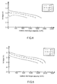
- the corresponding data is provided in the form of curves of voltage against battery discharge-capacity at different temperatures and different output currents, as shown in FIG. 4 and FIG. 5 .
- FIG. 4 there are shown curves of voltage against battery discharge-capacity at different temperatures of the battery module 130 of a UF515151SX lithium battery, with an output current of 2.100A.
- FIG. 5 there are shown curves of voltage against battery discharge-capacity at different temperatures of the battery module 130 of a UF515161SX lithium battery, with an output current of 0.420A.
- the processing unit 110 calculates a battery discharge-capacity with a corresponding data according to the temperature, voltage and output current of the battery module 130 by interpolation. For example, assuming that the corresponding data is provided in the form of curves of voltage against battery discharge-capacity at different temperatures and different output currents, the processing unit 110 selects a curve of voltage against battery discharge-capacity according to the temperature and output current of the battery module 130 and then use the voltage of the battery module 130 to obtain a preselected voltage and a preselected discharge-capacity which are correlated. Two preselected voltages approximate the voltage of the battery module 130.
- the processing unit 110 performs interpolation on the preselected voltage and the preselected discharge-capacity, which are correlated, as well as the voltage of the battery module 130 to obtain the battery discharge-capacity which the voltage of the battery module 130 corresponds to.
- the processing unit 110 estimates the battery discharge-capacity of the battery module 130 with the TI gauging technique whenever the temperature meets the predetermined condition, and estimates the battery discharge-capacity of the battery module 130 with a corresponding low-temperature data whenever the temperature does not meet the predetermined condition.
- the corresponding data is created by conducting a plurality of discharging tests on the battery module 130 and prestored in the storing unit 170 (step 202), as shown in FIG. 3 .
- the corresponding data is created by conducting a discharging test on a plurality of the battery modules with the same delivery condition as the battery module 130 and prestored in the storing unit 170 (step 202), as shown in FIG. 3 .
- the electronic device 10 comprises a display unit 180.
- the display unit 180 is coupled to the processing unit 110.
- the processing unit 110 displays a power percentage on the display unit 180 according to the calculated battery discharge-capacity (step S270) to inform the user of the residual discharge-capacity of the battery module 130.
- the power percentage displayed on the display unit 180 comes in the form of a battery icon or digits.
- the processing unit 110 calculates the power percentage according to the calculated battery discharge-capacity and the full load of the battery module 130, and then the display unit 180 displays a corresponding battery icon or digits according to the calculated power percentage.
- the processing unit 110 performs the detecting step, estimating step and displaying step (i.e., step S230, step S240 or S242 and step S270, or, alternatively, step S260, step S260 or S262 and step S270) repeatedly to discern and/or display the present residual discharge-capacity of the battery module 130.
- the processing unit 110 performs determining steps (i.e., step S210 and S220) anew at a predetermined time period to confirm the accepted way of estimating the battery discharge-capacity.
- the processing unit 110 is a microprocessor, a microcontroller, an embedded controller (EC) 30, a digital signal processor, a microcomputer, or a central processing unit (CPU).
- EC embedded controller
- CPU central processing unit
- the battery module 130 stores power.
- the battery module 130 is coupled to power supply ends of components (for example, the processing unit 110, the temperature sensing unit 150, the storing unit 170 and another component 190) of the electronic device 10.
- the battery module 130 supplies stored power to components (for example, the processing unit 110, the temperature sensing unit 150, the storing unit 170 and another component 190) of the electronic device 10, while the electronic device 10 is operating.
- the battery module 130 comprises one or more battery units.
- the storing unit 170 stores programs, parameters and data (for example, predetermined conditions, TI algorithms and corresponding data) required for operation and stores temporarily parameters and data generated in the course of operation.
- the storing unit 170 is provided in the form of one or more memory devices.
- the memory devices are ready-only memory (ROM), random access memory (RAM), static memory, dynamic memory, flash memory, and/ or any equipment for storing digital information.
- another component 190 is required for assisting the electronic device 10 in performing functional operations.
- a notebook a notebook
- another component 190 is exemplified by a motherboard, a cooling fan, a display card, a sound card, a wireless chip, a hard disk drive, a display unit, a user interface, or any combination thereof, but the present invention is not limited thereto.
- the electronic device 10 comes in the form of a tablet, a smartphone, a digital camera, an operating platform, a server, or a medical device.
- the present invention further provides a gauging method for a battery discharge-capacity corresponding to a temperature.
- the gauging method for a battery discharge-capacity corresponding to a temperature comprises the steps of: detecting a temperature of a battery module of the electronic device according to a predetermined condition; detecting the internal impedance of the battery module and estimating the battery discharge-capacity of the battery module according to the internal impedance if the temperature meets the predetermined condition; and detecting a voltage and an output current of the battery module and calculating the battery discharge-capacity of the battery module according to the temperature, the voltage and the output current if the temperature does not meet the predetermined condition.
- the gauging method for a battery discharge-capacity corresponding to a temperature is effectuated with a computer program product such that the gauging method for a battery discharge-capacity corresponding to a temperature is implemented according to any embodiment of the present invention by loading a program to an electronic device with a battery module and executing the program.
- the computer program product is a computer-readable medium, whereas the program is stored in the computer-readable medium so as to be loaded to the electronic device.
- the program is a computer program product and can be transmitted to the electronic device in a wired or wireless manner.
- a gauging method for a battery discharge-capacity corresponding to a temperature and an electronic device using the same are characterized in that: the electronic device estimates a residual discharge-capacity of a battery module by a hybrid battery algorithm so that, at a low temperature, the residual discharge-capacity of the battery module is precisely estimated, so as to prevent the electronic device from malfunctioning because of erroneous battery-related information and/or prevent the electronic device from shutting down unexpectedly because of power supply interruptions.
Landscapes
- Physics & Mathematics (AREA)
- General Physics & Mathematics (AREA)
- Engineering & Computer Science (AREA)
- Manufacturing & Machinery (AREA)
- Chemical & Material Sciences (AREA)
- Chemical Kinetics & Catalysis (AREA)
- Electrochemistry (AREA)
- General Chemical & Material Sciences (AREA)
- Secondary Cells (AREA)
Abstract
Description
- The present invention relates to battery discharge-capacity management technology and, more particularly, to a gauging method for a battery discharge-capacity corresponding to a temperature and an electronic device using the same.
- Portable electronic devices, such as mobile phones, notebooks (NB), and personal digital assistants (PDA), come into wide use rapidly, because they are powered by battery modules and thus portable.
- In practice, to meet voltage requirements, plenty application scenarios necessitate multiple series-connected unit batteries so as to effectuate a battery module operating at a required voltage. To enable the optimal performance of a battery module and extend the service life of the battery module, an electronic device is usually equipped with a battery management system for monitoring the battery module. The battery management system is useful in accessing state information pertaining to the battery module, providing overcharging/overdischarging protection, as well as equalizing battery voltage and/or estimating battery residual discharge-capacity. However, an unexpected insufficient power supply may cause the electronic device to shut down instantly and thus suffer a loss of data or get damaged. For the aforesaid reasons, recent years see the emergence of an important function of a battery module power supply system, that is, monitoring battery states in terms of temperature, voltage, current, residual capacitance state, and the like, to enable the optimal performance of battery modules.
- According to prior art, a battery management system of an electronic device estimates a battery residual discharge-capacity with a gauging technique developed by Texas Instruments (TI). However, at a low temperature, the TI gauging technique is obviously inaccurate and susceptible to erroneous judgements; as a result, the electronic device is likely to malfunction because of erroneous battery-related information.
- In an embodiment, a gauging method for a battery discharge-capacity corresponding to a temperature, comprising the steps of: detecting a temperature of a battery module of the electronic device according to a predetermined condition; detecting the internal impedance of the battery module and estimating the battery discharge-capacity of the battery module according to the internal impedance if the temperature meets the predetermined condition; and detecting a voltage and an output current of the battery module and calculating the battery discharge-capacity of the battery module according to the temperature, the voltage and the output current if the temperature does not meet the predetermined condition.
- In an embodiment, an electronic device for gauging a battery discharge-capacity corresponding to a temperature, comprising a battery module, a temperature sensing unit, a storing unit, and a processing unit. The processing unit is coupled to the battery module, the temperature sensing unit, and the storing unit. The battery module supplies power to the electronic device. The temperature sensing unit measures a temperature of the battery module. The storing unit stores a predetermined condition. The processing unit receives the temperature and confirms the received temperature according to the predetermined condition. If the temperature meets the predetermined condition, the processing unit will detect the internal impedance of the battery module and estimate the battery discharge-capacity of the battery module according to the internal impedance. If temperature does not meet the predetermined condition, the processing unit will detect a voltage and an output current of the battery module and calculate the battery discharge-capacity of the battery module according to the temperature, the voltage and the output current.
- In conclusion, according to embodiments of the present invention, a gauging method for a battery discharge-capacity corresponding to a temperature and an electronic device using the same are characterized in that: the electronic device estimates a residual discharge-capacity of a battery module by a hybrid battery algorithm so that, at a low temperature, the residual discharge-capacity of the battery module is precisely estimated, so as to prevent the electronic device from malfunctioning because of erroneous battery-related information and/or prevent the electronic device from shutting down unexpectedly because of power supply interruptions.
-
-
FIG. 1 is a function block diagram of an electronic device for gauging a battery discharge-capacity corresponding to a temperature according to an embodiment of the present invention; -
FIG. 2 is a flowchart of a gauging method for a battery discharge-capacity corresponding to a temperature according to an embodiment of the present invention; -
FIG. 3 is a flowchart of the gauging method for a battery discharge-capacity corresponding to a temperature according to another embodiment of the present invention; -
FIG. 4 is a schematic view of a corresponding data according to an embodiment of the present invention; and -
FIG. 5 is a schematic view of a corresponding data according to another embodiment of the present invention. - Referring to
FIG. 1 , an electronic device for gauging a battery discharge-capacity corresponding to a temperature (hereinafter abbreviated as "electronic device 10") comprises aprocessing unit 110, abattery module 130, atemperature sensing unit 150, astoring unit 170, and anothercomponent 190. Theprocessing unit 110 is coupled to thebattery module 130, thetemperature sensing unit 150, thestoring unit 170 and anothercomponent 190. Thetemperature sensing unit 150 is coupled to (in contact with) or positioned proximate to thebattery module 130. - Referring to
FIG. 2 , thetemperature sensing unit 150 is for measuring the temperature of the battery module 130 (step S212). The temperature of thebattery module 130 is the temperature of thebattery module 130 itself or the ambient temperature of thebattery module 130. - The
processing unit 110 receives the temperature measured by thetemperature sensing unit 150 and confirms the received temperature according to a predetermined condition (step S214), so as to confirm whether the temperature of thebattery module 130 meets the predetermined condition (step S220). - If the received temperature meets the predetermined condition, the
processing unit 110 will detect the internal impedance of the battery module 130 (step S230) and estimate the battery discharge-capacity of thebattery module 130 according to the detected internal impedance of thebattery module 130, that is, the residual discharge-capacity (step S240). Conversely, if the received temperature does not meet the predetermined condition, theprocessing unit 110 will detect the output current and the voltage of the battery module 130 (step S250) and calculate the battery discharge-capacity of thebattery module 130, that is, the residual discharge-capacity (step S260) according to the output current, the voltage, and the temperature of thebattery module 130. - In some embodiments, the predetermined condition is that the received temperature is higher than a temperature threshold. The
processing unit 110 compares the received temperature with a temperature threshold. If the received temperature is higher than the temperature threshold, theprocessing unit 110 will determine that the received temperature meets the predetermined condition. Conversely, if the received temperature is lower than or equal to the temperature threshold, theprocessing unit 110 will determine that the received temperature does not meet the predetermined condition. In some embodiments, the temperature threshold is 0°C. - In some embodiments of step S240, the
processing unit 110 estimates the battery discharge-capacity of thebattery module 130 according to the internal impedance detected with an algorithm developed by Texas Instruments (TI) (step S242), as shown inFIG. 3 . - In some embodiments of step S260, the
processing unit 110 calculates a battery discharge-capacity corresponding to the temperature, voltage and output current of thebattery module 130 with a corresponding data (step S262), as shown inFIG. 3 . In some embodiments, the corresponding data is provided in the form of curves of voltage against battery discharge-capacity at different temperatures and different output currents, as shown inFIG. 4 and FIG. 5 . Referring toFIG. 4 , there are shown curves of voltage against battery discharge-capacity at different temperatures of thebattery module 130 of a UF515151SX lithium battery, with an output current of 2.100A. Referring toFIG. 5 , there are shown curves of voltage against battery discharge-capacity at different temperatures of thebattery module 130 of a UF515161SX lithium battery, with an output current of 0.420A. - In some embodiments of step S260, the
processing unit 110 calculates a battery discharge-capacity with a corresponding data according to the temperature, voltage and output current of thebattery module 130 by interpolation. For example, assuming that the corresponding data is provided in the form of curves of voltage against battery discharge-capacity at different temperatures and different output currents, theprocessing unit 110 selects a curve of voltage against battery discharge-capacity according to the temperature and output current of thebattery module 130 and then use the voltage of thebattery module 130 to obtain a preselected voltage and a preselected discharge-capacity which are correlated. Two preselected voltages approximate the voltage of thebattery module 130. Afterward, theprocessing unit 110 performs interpolation on the preselected voltage and the preselected discharge-capacity, which are correlated, as well as the voltage of thebattery module 130 to obtain the battery discharge-capacity which the voltage of thebattery module 130 corresponds to. - Therefore, the
processing unit 110 estimates the battery discharge-capacity of thebattery module 130 with the TI gauging technique whenever the temperature meets the predetermined condition, and estimates the battery discharge-capacity of thebattery module 130 with a corresponding low-temperature data whenever the temperature does not meet the predetermined condition. - In some embodiments, the corresponding data is created by conducting a plurality of discharging tests on the
battery module 130 and prestored in the storing unit 170 (step 202), as shown inFIG. 3 . - In some embodiments, the corresponding data is created by conducting a discharging test on a plurality of the battery modules with the same delivery condition as the
battery module 130 and prestored in the storing unit 170 (step 202), as shown inFIG. 3 . - In some embodiments, the
electronic device 10 comprises adisplay unit 180. Thedisplay unit 180 is coupled to theprocessing unit 110. After calculating the battery discharge-capacity, theprocessing unit 110 displays a power percentage on thedisplay unit 180 according to the calculated battery discharge-capacity (step S270) to inform the user of the residual discharge-capacity of thebattery module 130. In some embodiments, the power percentage displayed on thedisplay unit 180 comes in the form of a battery icon or digits. For instance, theprocessing unit 110 calculates the power percentage according to the calculated battery discharge-capacity and the full load of thebattery module 130, and then thedisplay unit 180 displays a corresponding battery icon or digits according to the calculated power percentage. - In some embodiments, after a temperature judgment (step S220), the
processing unit 110 performs the detecting step, estimating step and displaying step (i.e., step S230, step S240 or S242 and step S270, or, alternatively, step S260, step S260 or S262 and step S270) repeatedly to discern and/or display the present residual discharge-capacity of thebattery module 130. - In some embodiments, the
processing unit 110 performs determining steps (i.e., step S210 and S220) anew at a predetermined time period to confirm the accepted way of estimating the battery discharge-capacity. - In some embodiments, the
processing unit 110 is a microprocessor, a microcontroller, an embedded controller (EC) 30, a digital signal processor, a microcomputer, or a central processing unit (CPU). - In some embodiments, the
battery module 130 stores power. Thebattery module 130 is coupled to power supply ends of components (for example, theprocessing unit 110, thetemperature sensing unit 150, thestoring unit 170 and another component 190) of theelectronic device 10. Thebattery module 130 supplies stored power to components (for example, theprocessing unit 110, thetemperature sensing unit 150, thestoring unit 170 and another component 190) of theelectronic device 10, while theelectronic device 10 is operating. In some embodiments, thebattery module 130 comprises one or more battery units. - In some embodiments, the storing
unit 170 stores programs, parameters and data (for example, predetermined conditions, TI algorithms and corresponding data) required for operation and stores temporarily parameters and data generated in the course of operation. The storingunit 170 is provided in the form of one or more memory devices. The memory devices are ready-only memory (ROM), random access memory (RAM), static memory, dynamic memory, flash memory, and/ or any equipment for storing digital information. - In some embodiments, another
component 190 is required for assisting theelectronic device 10 in performing functional operations. Take a notebook (NB) as an example, anothercomponent 190 is exemplified by a motherboard, a cooling fan, a display card, a sound card, a wireless chip, a hard disk drive, a display unit, a user interface, or any combination thereof, but the present invention is not limited thereto. In some embodiments, in addition to a notebook (NB), theelectronic device 10 comes in the form of a tablet, a smartphone, a digital camera, an operating platform, a server, or a medical device. - The present invention further provides a gauging method for a battery discharge-capacity corresponding to a temperature. The gauging method for a battery discharge-capacity corresponding to a temperature comprises the steps of: detecting a temperature of a battery module of the electronic device according to a predetermined condition; detecting the internal impedance of the battery module and estimating the battery discharge-capacity of the battery module according to the internal impedance if the temperature meets the predetermined condition; and detecting a voltage and an output current of the battery module and calculating the battery discharge-capacity of the battery module according to the temperature, the voltage and the output current if the temperature does not meet the predetermined condition.
- In some embodiments, according to the present invention, the gauging method for a battery discharge-capacity corresponding to a temperature is effectuated with a computer program product such that the gauging method for a battery discharge-capacity corresponding to a temperature is implemented according to any embodiment of the present invention by loading a program to an electronic device with a battery module and executing the program. In some embodiments, the computer program product is a computer-readable medium, whereas the program is stored in the computer-readable medium so as to be loaded to the electronic device. In some embodiments, the program is a computer program product and can be transmitted to the electronic device in a wired or wireless manner.
- In conclusion, according to embodiments of the present invention, a gauging method for a battery discharge-capacity corresponding to a temperature and an electronic device using the same are characterized in that: the electronic device estimates a residual discharge-capacity of a battery module by a hybrid battery algorithm so that, at a low temperature, the residual discharge-capacity of the battery module is precisely estimated, so as to prevent the electronic device from malfunctioning because of erroneous battery-related information and/or prevent the electronic device from shutting down unexpectedly because of power supply interruptions.
Claims (15)
- A gauging method for a battery discharge-capacity corresponding to a temperature, applicable to an electronic device (10), the gauging method comprising the steps of:detecting a temperature of a battery module (130) of the electronic device (10) according to a predetermined condition;detecting the internal impedance of the battery module (130) and estimating the battery discharge-capacity of the battery module (130) according to the internal impedance if the temperature meets the predetermined condition; anddetecting a voltage and an output current of the battery module (130) and calculating the battery discharge-capacity of the battery module (130) according to the temperature, the voltage and the output current if the temperature does not meet the predetermined condition.
- The gauging method for a battery discharge-capacity corresponding to a temperature according to claim 1, wherein the predetermined condition is that the received temperature is higher than a temperature threshold, wherein the step of detecting a temperature of a battery module (130) of the electronic device (10) according to a predetermined condition comprises:measuring the temperature of the battery module (130); andcomparing the temperature threshold with the temperature.
- The gauging method for a battery discharge-capacity corresponding to a temperature according to claim 2, wherein the temperature meets the predetermined condition when the temperature is higher than the temperature threshold, whereas the temperature does not meet the predetermined condition when the temperature is lower than or equal to the temperature threshold.
- The gauging method for a battery discharge-capacity corresponding to a temperature according to claim 1, wherein the step of estimating the battery discharge-capacity of the battery module (130) according to the internal impedance comprises estimating the battery discharge-capacity of the battery module (130) with a TI algorithm according to the internal impedance.
- The gauging method for a battery discharge-capacity corresponding to a temperature according to claim 1, wherein the step of calculating the battery discharge-capacity of the battery module (130) comprises calculating the battery discharge-capacity corresponding to the temperature, the voltage and the output current with a corresponding data.
- The gauging method for a battery discharge-capacity corresponding to a temperature according to claim 5, further comprising, before the step of detecting a temperature of a battery module (130) of the electronic device (10) according to a predetermined condition, conducting a discharging test on a plurality of battery modules with the same delivery condition as the battery module (130) to create the corresponding data.
- The gauging method for a battery discharge-capacity corresponding to a temperature according to claim 5, further comprising, before the step of detecting a temperature of a battery module (130) of the electronic device (10) according to a predetermined condition, conducting a plurality of discharging tests on the battery module (130) to create the corresponding data.
- The gauging method for a battery discharge-capacity corresponding to a temperature according to claim 5, wherein the step of calculating the battery discharge-capacity of the battery module (130) according to the temperature, the voltage and the output current comprises calculating the battery discharge-capacity with the corresponding data by interpolation.
- The gauging method for a battery discharge-capacity corresponding to a temperature according to claim 1, further comprising displaying a power percentage on a display unit (180) according to the battery discharge-capacity.
- An electronic device (10) for gauging a battery discharge-capacity corresponding to a temperature, comprising:a battery module (130) for suppling power to the electronic device (10);a temperature sensing unit (150) for measuring a temperature of the battery module (130);a storing unit (170) for storing a predetermined condition; anda processing unit (110) coupled to the battery module (130), the temperature sensing unit (150), and the storing unit (170) to receive the temperature,wherein, if the temperature meets the predetermined condition, the processing unit (110) will detect the internal impedance of the battery module (130) and estimate the battery discharge-capacity of the battery module (130) according to the internal impedance,wherein, if the temperature does not meet the predetermined condition, the processing unit (110) will detect a voltage and an output current of the battery module (130) and calculate the battery discharge-capacity of the battery module (130) according to the temperature, the voltage and the output current.
- The electronic device (10) for gauging a battery discharge-capacity corresponding to a temperature according to claim 10, wherein the predetermined condition is a temperature threshold.
- The electronic device (10) for gauging a battery discharge-capacity corresponding to a temperature according to claim 11, wherein the temperature meets the predetermined condition when the temperature is higher than the temperature threshold, and the temperature does not meet the predetermined condition when the temperature is not higher than the temperature threshold.
- The electronic device (10) for gauging a battery discharge-capacity corresponding to a temperature according to claim 10, wherein the storing unit (170) further stores a TI algorithm such that, when the temperature meets the predetermined condition, the processing unit (110) estimates the battery discharge-capacity of the battery module (130) with the TI algorithm according to the internal impedance.
- The electronic device for gauging a battery discharge-capacity corresponding to a temperature according to claim 10, wherein the storing unit (170) further stores a corresponding data such that, when the temperature does not meet the predetermined condition, the processing unit (110) calculates the battery discharge-capacity corresponding to the temperature, the voltage and the output current with the corresponding data.
- The electronic device (10) for gauging a battery discharge-capacity corresponding to a temperature according to claim 10, further comprising a display unit (180) coupled to the processing unit (110) to display a power percentage indicative of the battery discharge-capacity.
Priority Applications (1)
| Application Number | Priority Date | Filing Date | Title |
|---|---|---|---|
| EP16183045.0A EP3279678B1 (en) | 2016-08-05 | 2016-08-05 | Gauging method for battery discharge-capacity corresponding to temperature and electronic device using the same |
Applications Claiming Priority (1)
| Application Number | Priority Date | Filing Date | Title |
|---|---|---|---|
| EP16183045.0A EP3279678B1 (en) | 2016-08-05 | 2016-08-05 | Gauging method for battery discharge-capacity corresponding to temperature and electronic device using the same |
Publications (2)
| Publication Number | Publication Date |
|---|---|
| EP3279678A1 true EP3279678A1 (en) | 2018-02-07 |
| EP3279678B1 EP3279678B1 (en) | 2023-11-22 |
Family
ID=56693966
Family Applications (1)
| Application Number | Title | Priority Date | Filing Date |
|---|---|---|---|
| EP16183045.0A Active EP3279678B1 (en) | 2016-08-05 | 2016-08-05 | Gauging method for battery discharge-capacity corresponding to temperature and electronic device using the same |
Country Status (1)
| Country | Link |
|---|---|
| EP (1) | EP3279678B1 (en) |
Cited By (1)
| Publication number | Priority date | Publication date | Assignee | Title |
|---|---|---|---|---|
| CN118244134A (en) * | 2024-02-28 | 2024-06-25 | 上海正泰智能科技有限公司 | Battery power detection method, device, electronic equipment and storage medium |
Citations (5)
| Publication number | Priority date | Publication date | Assignee | Title |
|---|---|---|---|---|
| US6157169A (en) * | 1997-04-30 | 2000-12-05 | Samsung Electronics Co., Ltd. | Monitoring technique for accurately determining residual capacity of a battery |
| US20060164042A1 (en) * | 2005-01-25 | 2006-07-27 | Sim Se S | Apparatus and method for monitoring charging/discharging capacity of battery packs |
| US20120166116A1 (en) * | 2010-12-27 | 2012-06-28 | Denso Corporation | Apparatus for calculating residual capacity of secondary battery |
| US20140103933A1 (en) * | 2012-10-12 | 2014-04-17 | GM Global Technology Operations LLC | Method and system for estimating battery capacity in a vehicle |
| US20150025823A1 (en) * | 2013-07-16 | 2015-01-22 | Stmicroelectronics International N.V. | Temperature-compensated state of charge estimation for rechargeable batteries |
-
2016
- 2016-08-05 EP EP16183045.0A patent/EP3279678B1/en active Active
Patent Citations (5)
| Publication number | Priority date | Publication date | Assignee | Title |
|---|---|---|---|---|
| US6157169A (en) * | 1997-04-30 | 2000-12-05 | Samsung Electronics Co., Ltd. | Monitoring technique for accurately determining residual capacity of a battery |
| US20060164042A1 (en) * | 2005-01-25 | 2006-07-27 | Sim Se S | Apparatus and method for monitoring charging/discharging capacity of battery packs |
| US20120166116A1 (en) * | 2010-12-27 | 2012-06-28 | Denso Corporation | Apparatus for calculating residual capacity of secondary battery |
| US20140103933A1 (en) * | 2012-10-12 | 2014-04-17 | GM Global Technology Operations LLC | Method and system for estimating battery capacity in a vehicle |
| US20150025823A1 (en) * | 2013-07-16 | 2015-01-22 | Stmicroelectronics International N.V. | Temperature-compensated state of charge estimation for rechargeable batteries |
Non-Patent Citations (2)
| Title |
|---|
| MING YU ET AL: "Theory and Implementation of Impedance Track(TM) Battery Fuel-Gauging Algorithm in bq20zxx Product Family", 1 December 2006 (2006-12-01), XP055336672, Retrieved from the Internet <URL:http://www.ti.com/lit/an/slua364b/slua364b.pdf> [retrieved on 20170118] * |
| POP V ET AL: "REVIEW ARTICLE; State-of-the-art of battery state-of-charge determination; Review Article", MEASUREMENT SCIENCE AND TECHNOLOGY, IOP, BRISTOL, GB, vol. 16, no. 12, 1 December 2005 (2005-12-01), pages R93 - R110, XP020090492, ISSN: 0957-0233, DOI: 10.1088/0957-0233/16/12/R01 * |
Cited By (2)
| Publication number | Priority date | Publication date | Assignee | Title |
|---|---|---|---|---|
| CN118244134A (en) * | 2024-02-28 | 2024-06-25 | 上海正泰智能科技有限公司 | Battery power detection method, device, electronic equipment and storage medium |
| CN118244134B (en) * | 2024-02-28 | 2024-11-22 | 上海正泰智能科技有限公司 | Battery power detection method, device, electronic equipment and storage medium |
Also Published As
| Publication number | Publication date |
|---|---|
| EP3279678B1 (en) | 2023-11-22 |
Similar Documents
| Publication | Publication Date | Title |
|---|---|---|
| US10020548B2 (en) | Gauging method for battery discharge-capacity corresponding to temperature and electronic device using the same | |
| US20190120908A1 (en) | Apparatus and methods for identifying anomaly(ies) in re-chargeable battery of equipment and connected component(s) | |
| JP7463008B2 (en) | Battery cell diagnostic device and method | |
| US20110234167A1 (en) | Method of Predicting Remaining Capacity and Run-time of a Battery Device | |
| US10587135B2 (en) | Adaptive battery charging | |
| US9298909B2 (en) | Detecting status of an application program running in a device | |
| US8319479B2 (en) | Method of estimating battery recharge time and related device | |
| JP6458578B2 (en) | Battery state detection device, electronic device, and battery state detection method | |
| CN109217248B (en) | Fault processing method and system for connector | |
| US10324139B2 (en) | Method and electronic device for detecting internal short circuit in battery | |
| US11245278B2 (en) | Semiconductor device and battery pack | |
| US10955482B2 (en) | Method and device for acquiring battery power level and electronic device | |
| CN104502854A (en) | A terminal remaining power display method and device | |
| JP2009064682A (en) | Battery deterioration determination device and lithium ion battery pack provided with the same | |
| US12613279B2 (en) | Battery capacity estimation method, and battery module and electronic product using the same | |
| US20170024300A1 (en) | Diagnostic method, information processing device, and storage medium | |
| KR102709601B1 (en) | Apparatus and method for diagnosing battery cell | |
| CN115667961A (en) | Apparatus and method for diagnosing battery | |
| EP3279678B1 (en) | Gauging method for battery discharge-capacity corresponding to temperature and electronic device using the same | |
| US20060132097A1 (en) | Smart battery simulator | |
| KR101282137B1 (en) | Portable device and method of controlling thereof | |
| CN107643488A (en) | Corresponding to the metering method and its electronic installation of the battery electric quantity of temperature | |
| KR20180036237A (en) | Cell balancing control apparatus and method | |
| KR20210080068A (en) | Apparatus and method for diagnosing battery | |
| US12456877B2 (en) | Battery hazard detection |
Legal Events
| Date | Code | Title | Description |
|---|---|---|---|
| PUAI | Public reference made under article 153(3) epc to a published international application that has entered the european phase |
Free format text: ORIGINAL CODE: 0009012 |
|
| STAA | Information on the status of an ep patent application or granted ep patent |
Free format text: STATUS: THE APPLICATION HAS BEEN PUBLISHED |
|
| AK | Designated contracting states |
Kind code of ref document: A1 Designated state(s): AL AT BE BG CH CY CZ DE DK EE ES FI FR GB GR HR HU IE IS IT LI LT LU LV MC MK MT NL NO PL PT RO RS SE SI SK SM TR |
|
| AX | Request for extension of the european patent |
Extension state: BA ME |
|
| STAA | Information on the status of an ep patent application or granted ep patent |
Free format text: STATUS: REQUEST FOR EXAMINATION WAS MADE |
|
| 17P | Request for examination filed |
Effective date: 20180416 |
|
| RBV | Designated contracting states (corrected) |
Designated state(s): AL AT BE BG CH CY CZ DE DK EE ES FI FR GB GR HR HU IE IS IT LI LT LU LV MC MK MT NL NO PL PT RO RS SE SI SK SM TR |
|
| STAA | Information on the status of an ep patent application or granted ep patent |
Free format text: STATUS: EXAMINATION IS IN PROGRESS |
|
| 17Q | First examination report despatched |
Effective date: 20191016 |
|
| REG | Reference to a national code |
Ref legal event code: R079 Ref country code: DE Ref document number: 602016084248 Country of ref document: DE Free format text: PREVIOUS MAIN CLASS: G01R0031360000 Ipc: G01R0031367000 |
|
| GRAP | Despatch of communication of intention to grant a patent |
Free format text: ORIGINAL CODE: EPIDOSNIGR1 |
|
| STAA | Information on the status of an ep patent application or granted ep patent |
Free format text: STATUS: GRANT OF PATENT IS INTENDED |
|
| RIC1 | Information provided on ipc code assigned before grant |
Ipc: G01R 31/36 20060101ALN20230522BHEP Ipc: H01M 10/48 20060101ALI20230522BHEP Ipc: G01R 31/389 20190101ALI20230522BHEP Ipc: G01R 31/3842 20190101ALI20230522BHEP Ipc: G01R 31/374 20190101ALI20230522BHEP Ipc: G01R 31/367 20190101AFI20230522BHEP |
|
| INTG | Intention to grant announced |
Effective date: 20230612 |
|
| GRAS | Grant fee paid |
Free format text: ORIGINAL CODE: EPIDOSNIGR3 |
|
| GRAA | (expected) grant |
Free format text: ORIGINAL CODE: 0009210 |
|
| STAA | Information on the status of an ep patent application or granted ep patent |
Free format text: STATUS: THE PATENT HAS BEEN GRANTED |
|
| RAP3 | Party data changed (applicant data changed or rights of an application transferred) |
Owner name: GETAC HOLDINGS CORPORATION |
|
| AK | Designated contracting states |
Kind code of ref document: B1 Designated state(s): AL AT BE BG CH CY CZ DE DK EE ES FI FR GB GR HR HU IE IS IT LI LT LU LV MC MK MT NL NO PL PT RO RS SE SI SK SM TR |
|
| REG | Reference to a national code |
Ref country code: GB Ref legal event code: FG4D |
|
| REG | Reference to a national code |
Ref country code: CH Ref legal event code: EP Ref country code: DE Ref legal event code: R096 Ref document number: 602016084248 Country of ref document: DE |
|
| REG | Reference to a national code |
Ref country code: IE Ref legal event code: FG4D |
|
| REG | Reference to a national code |
Ref country code: DE Ref legal event code: R081 Ref document number: 602016084248 Country of ref document: DE Owner name: GETAC HOLDINGS CORPORATION, TW Free format text: FORMER OWNER: GETAC HOLDINGS CORP., TAIPEI CITY, TW |
|
| RAP4 | Party data changed (patent owner data changed or rights of a patent transferred) |
Owner name: GETAC HOLDINGS CORPORATION |
|
| REG | Reference to a national code |
Ref country code: LT Ref legal event code: MG9D |
|
| REG | Reference to a national code |
Ref country code: NL Ref legal event code: MP Effective date: 20231122 |
|
| PG25 | Lapsed in a contracting state [announced via postgrant information from national office to epo] |
Ref country code: GR Free format text: LAPSE BECAUSE OF FAILURE TO SUBMIT A TRANSLATION OF THE DESCRIPTION OR TO PAY THE FEE WITHIN THE PRESCRIBED TIME-LIMIT Effective date: 20240223 |
|
| PG25 | Lapsed in a contracting state [announced via postgrant information from national office to epo] |
Ref country code: IS Free format text: LAPSE BECAUSE OF FAILURE TO SUBMIT A TRANSLATION OF THE DESCRIPTION OR TO PAY THE FEE WITHIN THE PRESCRIBED TIME-LIMIT Effective date: 20240322 |
|
| PG25 | Lapsed in a contracting state [announced via postgrant information from national office to epo] |
Ref country code: LT Free format text: LAPSE BECAUSE OF FAILURE TO SUBMIT A TRANSLATION OF THE DESCRIPTION OR TO PAY THE FEE WITHIN THE PRESCRIBED TIME-LIMIT Effective date: 20231122 |
|
| REG | Reference to a national code |
Ref country code: AT Ref legal event code: MK05 Ref document number: 1634298 Country of ref document: AT Kind code of ref document: T Effective date: 20231122 |
|
| PG25 | Lapsed in a contracting state [announced via postgrant information from national office to epo] |
Ref country code: NL Free format text: LAPSE BECAUSE OF FAILURE TO SUBMIT A TRANSLATION OF THE DESCRIPTION OR TO PAY THE FEE WITHIN THE PRESCRIBED TIME-LIMIT Effective date: 20231122 |
|
| PG25 | Lapsed in a contracting state [announced via postgrant information from national office to epo] |
Ref country code: AT Free format text: LAPSE BECAUSE OF FAILURE TO SUBMIT A TRANSLATION OF THE DESCRIPTION OR TO PAY THE FEE WITHIN THE PRESCRIBED TIME-LIMIT Effective date: 20231122 |
|
| PG25 | Lapsed in a contracting state [announced via postgrant information from national office to epo] |
Ref country code: ES Free format text: LAPSE BECAUSE OF FAILURE TO SUBMIT A TRANSLATION OF THE DESCRIPTION OR TO PAY THE FEE WITHIN THE PRESCRIBED TIME-LIMIT Effective date: 20231122 |
|
| PG25 | Lapsed in a contracting state [announced via postgrant information from national office to epo] |
Ref country code: NL Free format text: LAPSE BECAUSE OF FAILURE TO SUBMIT A TRANSLATION OF THE DESCRIPTION OR TO PAY THE FEE WITHIN THE PRESCRIBED TIME-LIMIT Effective date: 20231122 Ref country code: LT Free format text: LAPSE BECAUSE OF FAILURE TO SUBMIT A TRANSLATION OF THE DESCRIPTION OR TO PAY THE FEE WITHIN THE PRESCRIBED TIME-LIMIT Effective date: 20231122 Ref country code: IS Free format text: LAPSE BECAUSE OF FAILURE TO SUBMIT A TRANSLATION OF THE DESCRIPTION OR TO PAY THE FEE WITHIN THE PRESCRIBED TIME-LIMIT Effective date: 20240322 Ref country code: GR Free format text: LAPSE BECAUSE OF FAILURE TO SUBMIT A TRANSLATION OF THE DESCRIPTION OR TO PAY THE FEE WITHIN THE PRESCRIBED TIME-LIMIT Effective date: 20240223 Ref country code: ES Free format text: LAPSE BECAUSE OF FAILURE TO SUBMIT A TRANSLATION OF THE DESCRIPTION OR TO PAY THE FEE WITHIN THE PRESCRIBED TIME-LIMIT Effective date: 20231122 Ref country code: BG Free format text: LAPSE BECAUSE OF FAILURE TO SUBMIT A TRANSLATION OF THE DESCRIPTION OR TO PAY THE FEE WITHIN THE PRESCRIBED TIME-LIMIT Effective date: 20240222 Ref country code: AT Free format text: LAPSE BECAUSE OF FAILURE TO SUBMIT A TRANSLATION OF THE DESCRIPTION OR TO PAY THE FEE WITHIN THE PRESCRIBED TIME-LIMIT Effective date: 20231122 Ref country code: PT Free format text: LAPSE BECAUSE OF FAILURE TO SUBMIT A TRANSLATION OF THE DESCRIPTION OR TO PAY THE FEE WITHIN THE PRESCRIBED TIME-LIMIT Effective date: 20240322 |
|
| PG25 | Lapsed in a contracting state [announced via postgrant information from national office to epo] |
Ref country code: SE Free format text: LAPSE BECAUSE OF FAILURE TO SUBMIT A TRANSLATION OF THE DESCRIPTION OR TO PAY THE FEE WITHIN THE PRESCRIBED TIME-LIMIT Effective date: 20231122 Ref country code: RS Free format text: LAPSE BECAUSE OF FAILURE TO SUBMIT A TRANSLATION OF THE DESCRIPTION OR TO PAY THE FEE WITHIN THE PRESCRIBED TIME-LIMIT Effective date: 20231122 Ref country code: PL Free format text: LAPSE BECAUSE OF FAILURE TO SUBMIT A TRANSLATION OF THE DESCRIPTION OR TO PAY THE FEE WITHIN THE PRESCRIBED TIME-LIMIT Effective date: 20231122 Ref country code: NO Free format text: LAPSE BECAUSE OF FAILURE TO SUBMIT A TRANSLATION OF THE DESCRIPTION OR TO PAY THE FEE WITHIN THE PRESCRIBED TIME-LIMIT Effective date: 20240222 Ref country code: LV Free format text: LAPSE BECAUSE OF FAILURE TO SUBMIT A TRANSLATION OF THE DESCRIPTION OR TO PAY THE FEE WITHIN THE PRESCRIBED TIME-LIMIT Effective date: 20231122 Ref country code: HR Free format text: LAPSE BECAUSE OF FAILURE TO SUBMIT A TRANSLATION OF THE DESCRIPTION OR TO PAY THE FEE WITHIN THE PRESCRIBED TIME-LIMIT Effective date: 20231122 |
|
| PG25 | Lapsed in a contracting state [announced via postgrant information from national office to epo] |
Ref country code: DK Free format text: LAPSE BECAUSE OF FAILURE TO SUBMIT A TRANSLATION OF THE DESCRIPTION OR TO PAY THE FEE WITHIN THE PRESCRIBED TIME-LIMIT Effective date: 20231122 |
|
| PG25 | Lapsed in a contracting state [announced via postgrant information from national office to epo] |
Ref country code: CZ Free format text: LAPSE BECAUSE OF FAILURE TO SUBMIT A TRANSLATION OF THE DESCRIPTION OR TO PAY THE FEE WITHIN THE PRESCRIBED TIME-LIMIT Effective date: 20231122 |
|
| PG25 | Lapsed in a contracting state [announced via postgrant information from national office to epo] |
Ref country code: SK Free format text: LAPSE BECAUSE OF FAILURE TO SUBMIT A TRANSLATION OF THE DESCRIPTION OR TO PAY THE FEE WITHIN THE PRESCRIBED TIME-LIMIT Effective date: 20231122 |
|
| PG25 | Lapsed in a contracting state [announced via postgrant information from national office to epo] |
Ref country code: SM Free format text: LAPSE BECAUSE OF FAILURE TO SUBMIT A TRANSLATION OF THE DESCRIPTION OR TO PAY THE FEE WITHIN THE PRESCRIBED TIME-LIMIT Effective date: 20231122 Ref country code: SK Free format text: LAPSE BECAUSE OF FAILURE TO SUBMIT A TRANSLATION OF THE DESCRIPTION OR TO PAY THE FEE WITHIN THE PRESCRIBED TIME-LIMIT Effective date: 20231122 Ref country code: RO Free format text: LAPSE BECAUSE OF FAILURE TO SUBMIT A TRANSLATION OF THE DESCRIPTION OR TO PAY THE FEE WITHIN THE PRESCRIBED TIME-LIMIT Effective date: 20231122 Ref country code: EE Free format text: LAPSE BECAUSE OF FAILURE TO SUBMIT A TRANSLATION OF THE DESCRIPTION OR TO PAY THE FEE WITHIN THE PRESCRIBED TIME-LIMIT Effective date: 20231122 Ref country code: DK Free format text: LAPSE BECAUSE OF FAILURE TO SUBMIT A TRANSLATION OF THE DESCRIPTION OR TO PAY THE FEE WITHIN THE PRESCRIBED TIME-LIMIT Effective date: 20231122 Ref country code: CZ Free format text: LAPSE BECAUSE OF FAILURE TO SUBMIT A TRANSLATION OF THE DESCRIPTION OR TO PAY THE FEE WITHIN THE PRESCRIBED TIME-LIMIT Effective date: 20231122 |
|
| REG | Reference to a national code |
Ref country code: DE Ref legal event code: R097 Ref document number: 602016084248 Country of ref document: DE |
|
| PLBE | No opposition filed within time limit |
Free format text: ORIGINAL CODE: 0009261 |
|
| STAA | Information on the status of an ep patent application or granted ep patent |
Free format text: STATUS: NO OPPOSITION FILED WITHIN TIME LIMIT |
|
| PGFP | Annual fee paid to national office [announced via postgrant information from national office to epo] |
Ref country code: DE Payment date: 20240731 Year of fee payment: 9 |
|
| PGFP | Annual fee paid to national office [announced via postgrant information from national office to epo] |
Ref country code: GB Payment date: 20240801 Year of fee payment: 9 |
|
| PGFP | Annual fee paid to national office [announced via postgrant information from national office to epo] |
Ref country code: FR Payment date: 20240801 Year of fee payment: 9 |
|
| PG25 | Lapsed in a contracting state [announced via postgrant information from national office to epo] |
Ref country code: SI Free format text: LAPSE BECAUSE OF FAILURE TO SUBMIT A TRANSLATION OF THE DESCRIPTION OR TO PAY THE FEE WITHIN THE PRESCRIBED TIME-LIMIT Effective date: 20231122 |
|
| 26N | No opposition filed |
Effective date: 20240823 |
|
| PG25 | Lapsed in a contracting state [announced via postgrant information from national office to epo] |
Ref country code: SI Free format text: LAPSE BECAUSE OF FAILURE TO SUBMIT A TRANSLATION OF THE DESCRIPTION OR TO PAY THE FEE WITHIN THE PRESCRIBED TIME-LIMIT Effective date: 20231122 |
|
| PGFP | Annual fee paid to national office [announced via postgrant information from national office to epo] |
Ref country code: IT Payment date: 20240822 Year of fee payment: 9 |
|
| REG | Reference to a national code |
Ref country code: CH Ref legal event code: PL |
|
| PG25 | Lapsed in a contracting state [announced via postgrant information from national office to epo] |
Ref country code: LU Free format text: LAPSE BECAUSE OF NON-PAYMENT OF DUE FEES Effective date: 20240805 |
|
| PG25 | Lapsed in a contracting state [announced via postgrant information from national office to epo] |
Ref country code: MC Free format text: LAPSE BECAUSE OF FAILURE TO SUBMIT A TRANSLATION OF THE DESCRIPTION OR TO PAY THE FEE WITHIN THE PRESCRIBED TIME-LIMIT Effective date: 20231122 Ref country code: CH Free format text: LAPSE BECAUSE OF NON-PAYMENT OF DUE FEES Effective date: 20240831 |
|
| REG | Reference to a national code |
Ref country code: BE Ref legal event code: MM Effective date: 20240831 |
|
| PG25 | Lapsed in a contracting state [announced via postgrant information from national office to epo] |
Ref country code: BE Free format text: LAPSE BECAUSE OF NON-PAYMENT OF DUE FEES Effective date: 20240831 |
|
| PG25 | Lapsed in a contracting state [announced via postgrant information from national office to epo] |
Ref country code: IE Free format text: LAPSE BECAUSE OF NON-PAYMENT OF DUE FEES Effective date: 20240805 |
|
| PG25 | Lapsed in a contracting state [announced via postgrant information from national office to epo] |
Ref country code: FI Free format text: LAPSE BECAUSE OF FAILURE TO SUBMIT A TRANSLATION OF THE DESCRIPTION OR TO PAY THE FEE WITHIN THE PRESCRIBED TIME-LIMIT Effective date: 20231122 |
|
| PG25 | Lapsed in a contracting state [announced via postgrant information from national office to epo] |
Ref country code: CY Free format text: LAPSE BECAUSE OF FAILURE TO SUBMIT A TRANSLATION OF THE DESCRIPTION OR TO PAY THE FEE WITHIN THE PRESCRIBED TIME-LIMIT; INVALID AB INITIO Effective date: 20160805 |
|
| REG | Reference to a national code |
Ref country code: DE Ref legal event code: R119 Ref document number: 602016084248 Country of ref document: DE |
|
| PG25 | Lapsed in a contracting state [announced via postgrant information from national office to epo] |
Ref country code: HU Free format text: LAPSE BECAUSE OF FAILURE TO SUBMIT A TRANSLATION OF THE DESCRIPTION OR TO PAY THE FEE WITHIN THE PRESCRIBED TIME-LIMIT; INVALID AB INITIO Effective date: 20160805 |
|
| GBPC | Gb: european patent ceased through non-payment of renewal fee |
Effective date: 20250805 |