EP3279593A1 - Steam-sterilization refrigerator and control method therefor - Google Patents
Steam-sterilization refrigerator and control method therefor Download PDFInfo
- Publication number
- EP3279593A1 EP3279593A1 EP16771161.3A EP16771161A EP3279593A1 EP 3279593 A1 EP3279593 A1 EP 3279593A1 EP 16771161 A EP16771161 A EP 16771161A EP 3279593 A1 EP3279593 A1 EP 3279593A1
- Authority
- EP
- European Patent Office
- Prior art keywords
- steam
- refrigerating compartment
- water
- steam generator
- tube
- Prior art date
- Legal status (The legal status is an assumption and is not a legal conclusion. Google has not performed a legal analysis and makes no representation as to the accuracy of the status listed.)
- Granted
Links
Images






Classifications
-
- F—MECHANICAL ENGINEERING; LIGHTING; HEATING; WEAPONS; BLASTING
- F25—REFRIGERATION OR COOLING; COMBINED HEATING AND REFRIGERATION SYSTEMS; HEAT PUMP SYSTEMS; MANUFACTURE OR STORAGE OF ICE; LIQUEFACTION SOLIDIFICATION OF GASES
- F25D—REFRIGERATORS; COLD ROOMS; ICE-BOXES; COOLING OR FREEZING APPARATUS NOT OTHERWISE PROVIDED FOR
- F25D17/00—Arrangements for circulating cooling fluids; Arrangements for circulating gas, e.g. air, within refrigerated spaces
- F25D17/04—Arrangements for circulating cooling fluids; Arrangements for circulating gas, e.g. air, within refrigerated spaces for circulating air, e.g. by convection
- F25D17/042—Air treating means within refrigerated spaces
-
- F—MECHANICAL ENGINEERING; LIGHTING; HEATING; WEAPONS; BLASTING
- F25—REFRIGERATION OR COOLING; COMBINED HEATING AND REFRIGERATION SYSTEMS; HEAT PUMP SYSTEMS; MANUFACTURE OR STORAGE OF ICE; LIQUEFACTION SOLIDIFICATION OF GASES
- F25D—REFRIGERATORS; COLD ROOMS; ICE-BOXES; COOLING OR FREEZING APPARATUS NOT OTHERWISE PROVIDED FOR
- F25D23/00—General constructional features
- F25D23/12—Arrangements of compartments additional to cooling compartments; Combinations of refrigerators with other equipment, e.g. stove
-
- A—HUMAN NECESSITIES
- A61—MEDICAL OR VETERINARY SCIENCE; HYGIENE
- A61L—METHODS OR APPARATUS FOR STERILISING MATERIALS OR OBJECTS IN GENERAL; DISINFECTION, STERILISATION OR DEODORISATION OF AIR; CHEMICAL ASPECTS OF BANDAGES, DRESSINGS, ABSORBENT PADS OR SURGICAL ARTICLES; MATERIALS FOR BANDAGES, DRESSINGS, ABSORBENT PADS OR SURGICAL ARTICLES
- A61L2/00—Disinfection or sterilisation of materials or objects, in general; Accessories therefor
- A61L2/02—Disinfection or sterilisation of materials or objects, in general; Accessories therefor using physical processes
- A61L2/04—Heat
- A61L2/06—Hot gas
- A61L2/07—Steam
-
- A—HUMAN NECESSITIES
- A61—MEDICAL OR VETERINARY SCIENCE; HYGIENE
- A61L—METHODS OR APPARATUS FOR STERILISING MATERIALS OR OBJECTS IN GENERAL; DISINFECTION, STERILISATION OR DEODORISATION OF AIR; CHEMICAL ASPECTS OF BANDAGES, DRESSINGS, ABSORBENT PADS OR SURGICAL ARTICLES; MATERIALS FOR BANDAGES, DRESSINGS, ABSORBENT PADS OR SURGICAL ARTICLES
- A61L2/00—Disinfection or sterilisation of materials or objects, in general; Accessories therefor
- A61L2/26—Accessories
-
- F—MECHANICAL ENGINEERING; LIGHTING; HEATING; WEAPONS; BLASTING
- F25—REFRIGERATION OR COOLING; COMBINED HEATING AND REFRIGERATION SYSTEMS; HEAT PUMP SYSTEMS; MANUFACTURE OR STORAGE OF ICE; LIQUEFACTION SOLIDIFICATION OF GASES
- F25D—REFRIGERATORS; COLD ROOMS; ICE-BOXES; COOLING OR FREEZING APPARATUS NOT OTHERWISE PROVIDED FOR
- F25D23/00—General constructional features
- F25D23/06—Walls
- F25D23/065—Details
-
- A—HUMAN NECESSITIES
- A61—MEDICAL OR VETERINARY SCIENCE; HYGIENE
- A61L—METHODS OR APPARATUS FOR STERILISING MATERIALS OR OBJECTS IN GENERAL; DISINFECTION, STERILISATION OR DEODORISATION OF AIR; CHEMICAL ASPECTS OF BANDAGES, DRESSINGS, ABSORBENT PADS OR SURGICAL ARTICLES; MATERIALS FOR BANDAGES, DRESSINGS, ABSORBENT PADS OR SURGICAL ARTICLES
- A61L2202/00—Aspects relating to methods or apparatus for disinfecting or sterilising materials or objects
- A61L2202/10—Apparatus features
- A61L2202/11—Apparatus for generating biocidal substances, e.g. vaporisers, UV lamps
-
- A—HUMAN NECESSITIES
- A61—MEDICAL OR VETERINARY SCIENCE; HYGIENE
- A61L—METHODS OR APPARATUS FOR STERILISING MATERIALS OR OBJECTS IN GENERAL; DISINFECTION, STERILISATION OR DEODORISATION OF AIR; CHEMICAL ASPECTS OF BANDAGES, DRESSINGS, ABSORBENT PADS OR SURGICAL ARTICLES; MATERIALS FOR BANDAGES, DRESSINGS, ABSORBENT PADS OR SURGICAL ARTICLES
- A61L2202/00—Aspects relating to methods or apparatus for disinfecting or sterilising materials or objects
- A61L2202/10—Apparatus features
- A61L2202/14—Means for controlling sterilisation processes, data processing, presentation and storage means, e.g. sensors, controllers, programs
-
- F—MECHANICAL ENGINEERING; LIGHTING; HEATING; WEAPONS; BLASTING
- F25—REFRIGERATION OR COOLING; COMBINED HEATING AND REFRIGERATION SYSTEMS; HEAT PUMP SYSTEMS; MANUFACTURE OR STORAGE OF ICE; LIQUEFACTION SOLIDIFICATION OF GASES
- F25D—REFRIGERATORS; COLD ROOMS; ICE-BOXES; COOLING OR FREEZING APPARATUS NOT OTHERWISE PROVIDED FOR
- F25D2317/00—Details or arrangements for circulating cooling fluids; Details or arrangements for circulating gas, e.g. air, within refrigerated spaces, not provided for in other groups of this subclass
- F25D2317/04—Treating air flowing to refrigeration compartments
- F25D2317/041—Treating air flowing to refrigeration compartments by purification
Definitions
- the steam sterilization refrigerator 1 includes the refrigerator body 20, the door body 30 and the steam generator 10.
- the steam outlet 1013 of the steam generator 10 is in direct communication with the refrigerating compartment 21 or in indirect communication with the refrigerating compartment 21 via the steam conveying channel 40.
- the temperature in the refrigerating compartment 21 maintains at 50 degrees Celsius to facilitate sterilization and defrosting; in the second sterilization mode, the temperature in the refrigerating compartment 21 maintains at 70 degrees Celsius to facilitate sterilization; in the first sterilization mode, the temperature in the refrigerating compartment 21 maintains at 90 degrees Celsius to facilitate sterilization and deodorization.
- the steam sterilization refrigerator 1 may further include an outer casing 106, the outer casing 106 may define a cavity 1061 therein, the steam generator 10 and the conveying pump 53 may be disposed in the cavity 1061, and a heat dissipation hole 1062 may be provided in the cavity 1061.
- the user can be prevented from being scalded, and also the heat in the outer casing 106 can be exhausted through the heat dissipation hole 1062 conveniently, that is, a part of the heat of the steam generator 10 can radiate to the environment through the heat dissipation hole 1062, such that the temperature of the steam generator 10 can be prevented from being too high.
- the temperature control protector 102 is a mechanical temperature controller, such as a temperature control tripping protector.
- a temperature control tripping protector When the temperature of the outer surface of the furnace body 101 is greater than or equal to the preset temperature, the temperature control tripping protector trips automatically to disconnect the electric heater 104 from the power source, thereby cutting off the power supply to the electric heater 104.
- the controller 83 control the relay 85 to turn on to communicate the electric heater 104 and the power source, in which case the electric heater 104 operates normally.
- the controller 83 control the relay 85 to turn off to disconnect the electric heater 104 from the power source, in which case the electric heater 104 stops heating.
- the controller 83 controls the steam generator 10 to stop.
- the controller 83 controls the steam generator 10 to stop through the relay 85, that is, the controller 83 controls the steam generator 10 to disconnect from the power source through the relay 85. So far, the sterilization process of the steam sterilization refrigerator 1 is completed.
Landscapes
- Engineering & Computer Science (AREA)
- Health & Medical Sciences (AREA)
- Chemical & Material Sciences (AREA)
- Combustion & Propulsion (AREA)
- Physics & Mathematics (AREA)
- Mechanical Engineering (AREA)
- Thermal Sciences (AREA)
- General Engineering & Computer Science (AREA)
- Epidemiology (AREA)
- Life Sciences & Earth Sciences (AREA)
- Animal Behavior & Ethology (AREA)
- General Health & Medical Sciences (AREA)
- Public Health (AREA)
- Veterinary Medicine (AREA)
- Cold Air Circulating Systems And Constructional Details In Refrigerators (AREA)
- Devices That Are Associated With Refrigeration Equipment (AREA)
- Apparatus For Disinfection Or Sterilisation (AREA)
- Disinfection, Sterilisation Or Deodorisation Of Air (AREA)
Abstract
Description
- The present disclosure relates to a field of household appliances, more particularly to a steam sterilization refrigerator and a control method for the steam sterilization refrigerator.
- A refrigerating compartment of a refrigerator can store vegetables, fruits, fishes, meats, or other food. After a period of use, the food in the refrigerating compartment of the refrigerator will breed bacteria, and produce unpleasant odor.
- In the related art, various solutions are proposed to sterilize and deodorize the refrigerator, for example, the sterilization can be performed by utilizing a filter, ozone, or ultraviolet rays. However, the above sterilization methods have the following defects. First, the ozone and ultraviolet rays are likely to cause harm to a human body; second, the sterilizing effect is poor: the sterilization methods of the related art generally sterilize only the air in the refrigerating compartment, while bacteria on a wall, a rack and a fruit and vegetable box of the refrigerating compartment cannot be killed, and bacteria which are not killed will continue to multiply after the sterilization is completed; third, the structure is complex along with large manufacturing difficulty and high manufacturing cost; fourth, the energy consumption is high because a fan for circulating the air in the refrigerating compartment needs to be used.
- The present disclosure seeks to solve at least one of the problems existing in the related art to at least some extent. To this end, the present disclosure proposes a steam sterilization refrigerator having advantages of a good sterilizing effect, low energy consumption and a simple structure.
- The steam sterilization refrigerator according to embodiments of a first aspect of the present disclosure includes: a refrigerator body having a refrigerating compartment and a compressor chamber therein; a door body disposed to the refrigerator body; and a steam generator disposed to at least one of the refrigerator body and the door body, the steam generator having a steam outlet, and the steam outlet being in direct communication with the refrigerating compartment or in indirect communication with the refrigerating compartment via a steam conveying channel.
- In the steam sterilization refrigerator according to embodiments of the present disclosure, by providing the steam generator and conveying steam produced in the steam generator into the refrigerating compartment, air in the refrigerating compartment can be sterilized, and also bacteria on a wall of the refrigerating compartment and bacteria attached to accessories in the refrigerating compartment can be killed. Therefore, the steam sterilization refrigerator according to embodiments of the present disclosure has advantages of the good sterilizing effect, the low energy consumption and the simple structure.
- Additionally, the steam sterilization refrigerator according to embodiments of the present disclosure may further have the following additional technical features.
- According to one embodiment of the present disclosure, the steam generator is disposed in the compressor chamber, a first side of the steam generator is provided with an inserting part connected to the refrigerator body in an inserting manner, a second side of the steam generator opposite to the first side is provided with a connecting part, and the connecting part is connected to the refrigerator body.
- According to one embodiment of the present disclosure, the steam generator is disposed to one of an upper surface, a left surface, a right surface and a rear surface of the refrigerator body, the steam conveying channel is formed by a steam conveying tube, a first end of the steam conveying tube is connected to the steam outlet, and a second end of the steam conveying tube penetrates a foaming layer of the refrigerator body and extends into the refrigerating compartment or is flush with a wall of the refrigerating compartment.
- According to one embodiment of the present disclosure, the steam sterilization refrigerator further includes a water tank detachably disposed to an upper surface of the refrigerator body; a flexible connecting tube; a first connecting tube having a first end connected to the water tank, and a second end detachably fitted in a first end of the flexible connecting tube; a conveying pump having a water outlet in communication with a water inlet of the steam generator; and a second connecting tube having a first end fitted in a second end of the flexible connecting tube, and a second end connected to a water inlet of the conveying pump.
- According to one embodiment of the present disclosure, an inner circumferential wall of the first end of the flexible connecting tube is provided with a first annular sealing flange and a second annular sealing flange, when the second end of the first connecting tube is fitted in the first end of the flexible connecting tube, an end surface of the second end of the first connecting tube abuts against the first annular sealing flange, and the second annular sealing flange abuts against a circumferential surface of the first connecting tube.
- According to one embodiment of the present disclosure, a plurality of first steam holes are provided in a wall of the refrigerating compartment and spaced apart in an up-and-down direction, and the steam conveying channel is formed in the refrigerator body and has a plurality of second steam holes in communication with the plurality of first steam holes in one-to-one correspondence.
- According to one embodiment of the present disclosure, the steam conveying channel is formed by a steam conveying tube, a first portion of the steam conveying tube is disposed in a foaming layer of the refrigerator body opposite to the refrigerating compartment, and the first portion of the steam conveying tube is provided with a plurality of second steam holes in communication with a plurality of first steam holes in one-to-one correspondence.
- According to one embodiment of the present disclosure, the steam generator is disposed in the refrigerating compartment, the steam sterilization refrigerator further includes a water tank disposed in the refrigerating compartment, the water tank has a water outlet hermetically connected to a water inlet of the steam generator, and the steam outlet of the steam generator is in direct communication with the refrigerating compartment.
- According to one embodiment of the present disclosure, the steam generator includes a furnace body and a water inlet tube, a first through hole being provided in the furnace body, and the water inlet tube being connected to the first through hole; the water tank includes a water tank body and a water outlet tube, a second through hole being provided in a wall of the water tank body, and the water outlet tube being connected to the second through hole; a part of the water inlet tube is fitted in the water outlet tube, and a sealing ring is disposed between the part of the water inlet tube and the water outlet tube.
- According to one embodiment of the present disclosure, the part of the water inlet tube is detachably fitted in the water outlet tube, and the water tank further includes a valve disc movable between a closed position where an inlet of the water outlet tube is closed and an open position where the inlet of the water outlet tube is open; a valve stem disposed in the water outlet tube and connected to the valve disc, the valve stem being driven to move the valve disc from the closed position to the open position when the water inlet tube is inserted into and fitted in the water outlet tube; and an elastic element disposed between the valve stem and the water outlet tube and normally pushing the valve stem and the valve disc towards the closed position.
- According to one embodiment of the present disclosure, a wall of the refrigerating compartment is provided with a first limiting member, the water tank is provided with a second limiting member fitted with the first limiting member, and the water tank is spaced apart from the steam generator at a preset distance when the second limiting member is in contact with the first limiting member.
- According to one embodiment of the present disclosure, the steam sterilization refrigerator further includes a plurality of racks disposed in the refrigerating compartment and spaced apart from one another in an up-and-down direction, the steam generator and the water tank being disposed between a bottom wall of the refrigerating compartment and a bottom one of the racks; and an air duct cover plate disposed in the refrigerating compartment and located behind the plurality of the racks, the steam conveying channel being defined between the air duct cover plate and a wall of the refrigerating compartment, the air duct cover plate being provided with a plurality of steam holes in communication with the steam conveying channel, the plurality of steam holes being spaced apart from one another in the up-and-down direction, and each space of a space between adjacent racks and a space between a top one of the racks and a top wall of the refrigerating compartment corresponding to at least one of the steam holes.
- According to one embodiment of the present disclosure, the steam sterilization refrigerator further includes a plurality of racks disposed in the refrigerating compartment and spaced apart from one another in an up-and-down direction, the steam generator and the water tank being disposed between a bottom wall of the refrigerating compartment and a bottom one of the racks, in which the steam conveying channel is formed by a steam conveying tube disposed in the refrigerating compartment, a lower port of the steam conveying tube is in communication with the steam outlet, a plurality of steam holes are provided in the steam conveying tube and spaced apart from one another in the up-and-down direction, and each space of a space between adjacent racks and a space between a top one of the racks and a top wall of the refrigerating compartment corresponds to at least one of the steam holes.
- According to one embodiment of the present disclosure, the steam sterilization refrigerator further includes a storage box disposed in the refrigerating compartment and capable of being pushed into and pulled out of the refrigerating compartment, the storage box having a storage chamber adapted to accommodate water and articles, and the storage chamber being in communication with a water inlet of the steam generator to supply the water in the storage chamber to the steam generator.
- According to one embodiment of the present disclosure, the steam sterilization refrigerator further includes a water inlet transition member disposed in the refrigerating compartment, a water flow channel being defined in the water inlet transition member, and the water flow channel having an inlet and an outlet; a first water inlet tube disposed to the storage box and having a first end in communication with the storage chamber and a second end in connection with the inlet of the water inlet transition member when the storage box is located in the refrigerating compartment; and a second water inlet tube having a first end connected to the outlet of the water inlet transition member, and a second end in communication with the water inlet of the steam generator.
- According to one embodiment of the present disclosure, the steam sterilization refrigerator further includes an air duct component, a ventilating channel being defined in the air duct component or between the air duct component and a wall of the refrigerating compartment, the ventilating channel being in communication with each of the refrigerating compartment and the steam outlet, and the steam conveying channel being formed by the ventilating channel; an evaporator disposed in the ventilating channel; and a fan disposed in the ventilating channel to convey steam and cold air into the refrigerating compartment.
- According to one embodiment of the present disclosure, the refrigerator body has a refrigerating chamber and a freezing chamber therein, and the ventilating channel is in communication with each of the refrigerating chamber, the freezing chamber and the steam outlet.
- According to one embodiment of the present disclosure, the steam sterilization refrigerator further includes a steam connecting tube having a first end connected to the steam outlet, and a second end extending into the ventilating channel and opening towards the evaporator.
- According to one embodiment of the present disclosure, the steam generator includes a furnace body and an electric heater, an accommodating cavity for accommodating water is defined in the furnace body therein, the accommodating cavity has a water inlet and the steam outlet, the electric heater is adapted to be connected to a power source through a power cord. Moreover, the steam sterilization refrigerator further includes: a conveying pump having a water outlet in communication with the water inlet of the steam generator; a temperature control protector disposed to an outer surface of the furnace body and configured to sense a temperature of the outer surface of the furnace body, the temperature control protector being connected to the power cord and automatically turning off when the temperature of the outer surface of the furnace body is greater than or equal to a preset temperature; a temperature sensor disposed to the outer surface of the furnace body and configured to sense the temperature of the outer surface of the furnace body; and a controller connected to the temperature sensor and the electric heater and controlling the electric heater to stop heating when the temperature of the outer surface of the furnace body is greater than or equal to the preset temperature.
- According to one embodiment of the present disclosure, the controller is connected to an electric motor of the conveying pump to monitor a working current of the electric motor of the conveying pump, the steam sterilization refrigerator further includes a first indicator light and a second indicator light, each of the first indicator light and the second indicator light being connected to the controller, in which when the working current of the electric motor of the conveying pump is within a preset range and the electric heater stops heating, the controller controls the first indicator light to glow or flicker, and when the working current of the electric motor of the conveying pump exceeds the preset range and the electric heater stops heating, the controller controls the second indicator light to glow or flicker.
- According to one embodiment of the present disclosure, the steam sterilization refrigerator further includes a voice reminder connected to the controller, in which when a working current of an electric motor of the conveying pump is within a preset range and the electric heater stops heating, the controller controls the voice reminder to give out a first reminding voice, and when the working current of the electric motor of the conveying pump exceeds the preset range and the electric heater stops heating, the controller controls the voice reminder to give out a second reminding voice.
- According to one embodiment of the present disclosure, the steam sterilization refrigerator further includes a water level gauge configured to detect a water level in a water tank; a water-shortage indicator light and a full-water indicator light both disposed in the refrigerating compartment; and a controller connected to each of the water level gauge, the water-shortage indicator light, the full-water indicator light and the steam generator, in which the controller controls the water-shortage indicator light to glow or flicker when a water level detection value of the water level gauge is smaller than a first preset value, and controls the full-water indicator light to glow or flicker when the water level detection value of the water level gauge is greater than a second preset value.
- A control method for a steam sterilization refrigerator is provided according to embodiments of a second aspect of the present disclosure, in which the steam sterilization refrigerator includes a refrigerator body defining a refrigerating compartment therein, a compressor and a steam generator. The control method includes steps: controlling the steam generator to operate to supply steam to the refrigerating compartment; detecting a temperature in the refrigerating compartment and starting timing when a detected temperature value reaches a first preset value; and controlling the steam generator to stop when the timing reaches a first preset time.
- By utilizing the control method according to embodiments of the present disclosure, the refrigerating compartment can be effectively sterilized to make the refrigerating compartment cleaner and more hygienic, and hence requirements of a user can be better satisfied.
- According to one embodiment of the present disclosure, the first preset value is 60-80 degrees Celsius, and the first preset time is 10-40 minutes.
- According to one embodiment of the present disclosure, the control method further include: comparing the detected temperature value with the first preset value before the timing reaches the first preset time, when the detected temperature value is greater than the first preset value, controlling the steam generator to stop after a delay of a second preset time, and when the detected temperature value is smaller than or equal to the first preset value, controlling the steam generator to operate.
- According to one embodiment of the present disclosure, the control method further includes: detecting a temperature of the steam generator, and controlling the steam generator to stop when the temperature of the steam generator reaches a second preset value.
- According to one embodiment of the present disclosure, the first preset value is 60-80 degrees Celsius, the second preset value is 160-200 degrees Celsius, and the first preset time is 10-40 minutes.
- According to one embodiment of the present disclosure, water is supplied to the steam generator when a temperature of the steam generator reaches 50 degrees Celsius to 80 degrees Celsius.
- According to one embodiment of the present disclosure, after the steam generator is controlled to supply steam to the refrigerating compartment for a third preset time, and when the temperature in the refrigerating compartment is smaller than the first preset value, the steam generator is controlled to stop.
- According to one embodiment of the present disclosure, the third preset time is 35-45 minutes.
-
-
Fig. 1 illustrates a schematic view of a steam sterilization refrigerator according to an embodiment of the present disclosure. -
Fig. 2 illustrates a schematic view of a steam sterilization refrigerator according to a first embodiment of the present disclosure. -
Fig. 3 illustrates a partially schematic view of the steam sterilization refrigerator according to the first embodiment of the present disclosure. -
Fig. 4 illustrates a schematic view of a flexible connecting tube of the steam sterilization refrigerator according to the first embodiment of the present disclosure. -
Fig. 5 illustrates a partially schematic view of the steam sterilization refrigerator according to the first embodiment of the present disclosure. -
Fig. 6 illustrates a schematic view of a steam sterilization refrigerator according to a second embodiment of the present disclosure. -
Fig. 7 illustrates a schematic view of the steam sterilization refrigerator according to the second embodiment of the present disclosure. -
Fig. 8 illustrates a schematic view of the steam sterilization refrigerator according to the second embodiment of the present disclosure. -
Fig. 9 illustrates a schematic view of a water storage box of the steam sterilization refrigerator according to the second embodiment of the present disclosure. -
Fig. 10 illustrates a partially schematic view of the steam sterilization refrigerator according to the second embodiment of the present disclosure. -
Fig. 11 illustrates a schematic view of a steam sterilization refrigerator according to a third embodiment of the present disclosure. -
Fig. 12 illustrates a partially exploded view of the steam sterilization refrigerator according to the third embodiment of the present disclosure. -
Fig. 13 illustrates a sectional view of a water inlet transition member of the steam sterilization refrigerator according to the third embodiment of the present disclosure. -
Fig. 14 illustrates a schematic view of a steam sterilization refrigerator according to a fourth embodiment of the present disclosure. -
Fig. 15 illustrates a schematic view of a steam sterilization assembly of the steam sterilization refrigerator according to the fourth embodiment of the present disclosure. -
Fig. 16 illustrates a schematic view of a steam sterilization device of a steam sterilization refrigerator according to a fifth embodiment of the present disclosure. -
Fig. 17 illustrates a schematic view of temperature control and protection for the steam sterilization device of the steam sterilization refrigerator according to the fifth embodiment of the present disclosure. -
Fig. 18 illustrates a schematic view of a steam sterilization refrigerator according to a sixth embodiment of the present disclosure. -
Fig. 19 illustrates a schematic view of a steam sterilization assembly of the steam sterilization refrigerator according to the sixth embodiment of the present disclosure. -
Fig. 20 illustrates a partially schematic view of the steam sterilization refrigerator according to the sixth embodiment of the present disclosure. -
Fig. 21 illustrates a partially schematic view of the steam sterilization refrigerator according to the sixth embodiment of the present disclosure. -
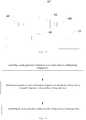
Fig. 22 illustrates a flow diagram of a control method for a steam sterilization refrigerator according to an embodiment of the present disclosure. -
Fig. 23 illustrates a flow diagram of a control method for a steam sterilization refrigerator according to an embodiment of the present disclosure. -
Fig. 24 illustrates a flow diagram of a control method for a steam sterilization refrigerator according to an embodiment of the present disclosure. - Embodiments of the present disclosure will be described in detail below, and examples of the embodiments are shown in accompanying drawings. The embodiments described herein with reference to drawings are explanatory, illustrative, and used to generally understand the present disclosure. The embodiments shall not be construed to limit the present disclosure.
- A sterilization refrigerator in the related art is provided with an air hose in communication with a refrigerating compartment, and the air hose is provided with a fan therein. When the sterilization refrigerator performs sterilization, the fan operates to suck air in the refrigerating compartment into the air hose. Then the air sucked into the air hose is sterilized to obtain sterile air. Finally, the fan blows the sterile air into the refrigerating compartment. That is to say, under the function of the fan, the air is circulated in the refrigerating compartment and the air hose, and the air is sterilized during the circulation.
- However, the sterilization refrigerator has the following defects. First, the sterilizing effect is poor: only the air in the refrigerating compartment can be sterilized by the sterilization refrigerator, but bacteria on a wall of the refrigerating compartment and bacteria attached to accessories (such as a storage box and a rack) of the refrigerating compartment cannot be killed, and the bacteria which are not killed will continue to multiply after the sterilization is completed. Second, the structure is complex along with large manufacturing difficulty and high manufacturing cost: the refrigerator needs to be provided with the air hose in communication with the refrigerating compartment, both an inlet and an outlet of the air hose need to be communicated with the refrigerating compartment, and an sterilization unit and the fan need to be disposed in the air hose, which significantly increases the manufacturing difficulty and manufacturing cost of the refrigerator; additionally, a biosensor and an odor sensor are provided in order to detect a pollution source, which also increases the manufacturing cost of the sterilization refrigerator. Third, the energy consumption is high: during sterilization, the fan is required to operate, which leads to an increase in the energy consumption of the sterilization refrigerator.
- A
steam sterilization refrigerator 1 according to an embodiment of the present disclosure will be described below with reference to the drawings. As illustrated inFigs. 1 to 21 , thesteam sterilization refrigerator 1 according to embodiments of the present disclosure includes arefrigerator body 20, adoor body 30 and asteam generator 10. - The
refrigerator body 20 has arefrigerating compartment 21 and acompressor chamber 22 therein, and thedoor body 30 is disposed to therefrigerator body 20. Thesteam generator 10 is disposed to at least one of therefrigerator body 20 and thedoor body 30, thesteam generator 10 has asteam outlet 1013, and thesteam outlet 1013 is in direct communication with therefrigerating compartment 21 or in indirect communication with therefrigerating compartment 21 via asteam conveying channel 40. - In the
steam sterilization refrigerator 1 according to embodiments of the present disclosure, by providing thesteam generator 10 and communicating thesteam outlet 1013 of thesteam generator 10 with therefrigerating compartment 21, steam produced by thesteam generator 10 can be conveyed into therefrigerating compartment 21. Thus, air in therefrigerating compartment 21 can be sterilized, and also bacteria on a wall of therefrigerating compartment 21 and bacteria attached to accessories (such as a storage box and a rack) in therefrigerating compartment 21 can be killed. Therefore, thesteam sterilization refrigerator 1 according to embodiments of the present disclosure has an advantage of a good sterilizing effect. - Moreover, the
steam sterilization refrigerator 1 according to embodiments of the present disclosure does not need to evacuate the air in the refrigerating compartment and the steam produced by thesteam generator 10 can enter therefrigerating compartment 21 without using a fan. Therefore, thesteam sterilization refrigerator 1 according to embodiments of the present disclosure does not need to be provided with an exhaust tube and the fan. Thesteam sterilization refrigerator 1 according to embodiments of the present disclosure does not need to be provided with the biosensor and the odor sensor, either. Thus, a structure of thesteam sterilization refrigerator 1 is simplified, and the manufacturing difficulty and manufacturing cost of thesteam sterilization refrigerator 1 is reduced. - In addition, when the
steam sterilization refrigerator 1 performs sterilization, since the steam needs to be supplied into therefrigerating compartment 21, articles in therefrigerating compartment 21 are required to be taken out before the sterilization. Thus, during the sterilization, the refrigeratingcompartment 21 does not need to be refrigerated, and the fan does not need to be operated. Therefore, thesteam sterilization refrigerator 1 according to embodiments of the present disclosure further has an advantage of low energy consumption. - Therefore, the
steam sterilization refrigerator 1 according to embodiments of the present disclosure has advantages of the good sterilizing effect, the simple structure, the low manufacturing difficulty, the low manufacturing cost, and the low energy consumption. - As illustrated in
Figs. 1 to 21 , in some embodiments of the present disclosure, thesteam sterilization refrigerator 1 includes therefrigerator body 20, thedoor body 30 and thesteam generator 10. Thesteam outlet 1013 of thesteam generator 10 is in direct communication with therefrigerating compartment 21 or in indirect communication with therefrigerating compartment 21 via thesteam conveying channel 40. - Specifically, in the present application, the direct communication between the
steam outlet 1013 and therefrigerating compartment 1011 means that thesteam generator 10 is placed in therefrigerating compartment 21 or thesteam generator 10 is disposed to a rear surface of thedoor body 30, thesteam outlet 1013 may not be provided with a valve and/or a segment of tube, and then the steam directly enters therefrigerating compartment 21 after coming out of thesteam outlet 1013. Furthermore, thesteam outlet 1013 may also be provided with a valve and/or a nozzle and/or a segment of tube (which may also be referred to as a straight-through valve, a straight-through nozzle and a straight-through tube), and then the steam enters therefrigerating compartment 1011 after coming out of the straight-through valve and/or the straight-through nozzle and/or the straight-through tube mounted to thesteam outlet 1013. One objective of mounting the straight-through valve and/or the straight-through nozzle and/or the straight-through tube at thesteam outlet 1013 is to obtain an additional technical effect. For example, by mounting the straight-through tube at thesteam outlet 1013, the steam can be directly conveyed to a preset position; by mounting the straight-through nozzle at thesteam outlet 1013, a flow velocity of the steam can be improved. - The indirect communication between the
steam outlet 1013 and therefrigerating compartment 21 via thesteam conveying channel 40 means that thesteam generator 10 is disposed outside the refrigeratingcompartment 21, a first end of thesteam conveying channel 40 is in communication with thesteam outlet 1013, and a second end of thesteam conveying channel 40 is in communication with therefrigerating compartment 21. - It should be understood by those skilled in the art that, when the
refrigerator body 20 has a plurality of refrigeratingcompartments 21 therein, thesteam generator 10 may not be disposed in any one of the refrigerating compartments 21, and then thesteam outlet 1013 is in indirect communication with at least one of the refrigerating compartments 21 via thesteam conveying channel 40 in communication with thesteam outlet 1013. Thesteam generator 10 may also be disposed in one of the refrigerating compartments 21, and then thesteam outlet 1013 is in direct communication with this one of the refrigerating compartments 21 and in indirect communication with the rest of the refrigerating compartments 21 via thesteam conveying channel 40. For example, thesteam outlet 1013 may be connected to a plurality of tubes, one of the tubes (the straight-through tube) is in direct communication with onerefrigerating compartment 21 where thesteam generator 10 is placed, and thesteam outlet 1013 may be in indirect communication with at least one of the refrigerating compartments 21 without being provided with thesteam generator 10, via the rest of the tubes (i.e. the steam conveying channel 40). - As illustrated in
Figs. 1 ,14 and15 , thesteam generator 10 is disposed in thecompressor chamber 22, a first side of thesteam generator 10 is provided with a insertingpart 1014 connected to therefrigerator body 20 in an inserting manner, and a second side of thesteam generator 10 opposite to the first side is provided with a connectingpart 1015 connected to therefrigerator body 20. - Advantageously, a plurality of
steam generators 10 may be provided, such that a sterilization speed of thesteam sterilization refrigerator 1 can be improved. The plurality of thesteam generators 10 may all be disposed to therefrigerator body 20, or the plurality of thesteam generators 10 may all be disposed to thedoor body 30. Thesteam sterilization refrigerator 1 further includes a water collecting pipe (not illustrated) configured to collect condensed water in therefrigerating compartment 21, and the water collecting pipe is in communication with awater tank 50. - The
steam sterilization refrigerator 1 further includes a plurality of sterilization mode trigger keys, and a temperature sensor configured to measure a temperature in therefrigerating compartment 21. Thesteam generator 10 operates, according to trigger of the sterilization mode trigger key, in a sterilization mode corresponding to the triggered sterilization mode trigger key. The temperature sensor is connected to the plurality of sterilization mode trigger keys, and the plurality of sterilization mode trigger keys control thesteam generator 10 to stop operating when the temperature sensor detects that the temperature in therefrigerating compartment 21 is within a preset temperature range. - That is to say, each of the sterilization mode trigger keys is electrically connected to the
steam generator 10 and configured to output a corresponding trigger electrical signal, and thesteam generator 10 adjusts a corresponding sterilization mode according to the corresponding trigger electrical signal output by the sterilization mode trigger key. - Specifically, the sterilization mode includes a first sterilization mode, a second sterilization mode and a third sterilization mode. In the first sterilization mode, the
steam generator 10 maintains the temperature in therefrigerating compartment 21 within a range of 60 degrees Celsius to 80 degrees Celsius for a first period of time. In the second sterilization mode, thesteam generator 10 maintains the temperature in therefrigerating compartment 21 within a range of 80 degrees Celsius to 95 degrees Celsius for a second period of time. In the third sterilization mode, thesteam generator 10 maintains the temperature in therefrigerating compartment 21 within a range of 40 degrees Celsius to 60 degrees Celsius for a third period of time. - That is to say, in the third sterilization mode, the temperature in the
refrigerating compartment 21 is greater than or equal to 40 degrees Celsius and smaller than 60 degrees Celsius; in the second sterilization mode, the temperature in therefrigerating compartment 21 is greater than or equal to 60 degrees Celsius and smaller than 80 degrees Celsius; in the first sterilization mode, the temperature in therefrigerating compartment 21 is greater than or equal to 80 degrees Celsius and smaller than 95 degrees Celsius. - Advantageously, in the third sterilization mode, the temperature in the
refrigerating compartment 21 maintains at 50 degrees Celsius to facilitate sterilization and defrosting; in the second sterilization mode, the temperature in therefrigerating compartment 21 maintains at 70 degrees Celsius to facilitate sterilization; in the first sterilization mode, the temperature in therefrigerating compartment 21 maintains at 90 degrees Celsius to facilitate sterilization and deodorization. - As illustrated
Figs. 2 to 4 , in a first embodiment of the present disclosure, thesteam generator 10 is disposed to one of an upper surface, a left surface, a right surface and a rear surface of therefrigerator body 20, and thesteam conveying channel 40 is formed by asteam conveying tube 41. A first end of thesteam conveying tube 41 is connected to thesteam outlet 1013, and a second end of thesteam conveying tube 41 penetrates afoaming layer 23 of therefrigerator body 20 and extends into therefrigerating compartment 21 or is flush with the wall of therefrigerating compartment 21. A front-and-rear direction is as indicated by arrow A inFig. 1 , and an up-and-down direction is as indicated by arrow B inFig. 2 . - By providing the
steam generator 10 to one of the upper surface, the left surface, the right surface and the rear surface, the water can be filled in thesteam generator 10 conveniently, and also heat dissipation of thesteam generator 10 can be facilitated to prevent the heat produced by thesteam generator 10 from influencing normal refrigeration of thesteam refrigerating compartment 21 when refrigeration is required after completion of the sterilization, thereby avoiding an increase in a load of thesteam sterilization refrigerator 1. - As illustrated in
Fig. 2 , thesteam sterilization refrigerator 1 further includes thewater tank 50, a flexible connectingtube 51, a first connectingtube 52, a conveyingpump 53 and a second connectingtube 54. Thewater tank 50 is detachably disposed to the upper surface of therefrigerator body 20. A first end of the first connectingtube 52 is connected to thewater tank 50, and a second end of the first connectingtube 52 is detachably fitted in a first end of the flexible connectingtube 51. A first end of the second connectingtube 54 is fitted in a second end of the flexible connectingtube 51, and a second end of the second connectingtube 54 is connected to a water inlet of the conveyingpump 53. A water outlet of the conveyingpump 53 is in communication with awater inlet 1012 of thesteam generator 10. - The water in the
water tank 50 can be conveyed into thesteam generator 10, such that thesteam generator 10 can produce the steam continuously. Specifically, the water in thewater tank 50 enters thesteam generator 10 passing through the first connectingtube 52, the flexible connectingtube 51 and the second connectingtube 54 sequentially. - Since the
water tank 50 is detachably disposed to therefrigerator body 20, thewater tank 50 can be disassembled for water injection, such that the user can fill water into thewater tank 50 conveniently. Furthermore, by detachably fitting the second end of the first connectingtube 52 in the first end of the flexible connectingtube 51, the first connectingtube 52 can be removed along with thewater tank 50, and after thewater tank 50 is filled with the water, the first connectingtube 52 can be connected to the flexible connectingtube 51 again to facilitate conveying of the water in thewater tank 50 into thesteam generator 10. - The conveying
pump 53 can convey the water in thewater tank 50 into thesteam generator 10 automatically. Advantageously, the conveyingpump 53 is a peristaltic pump, and the second connectingtube 54 is fitted in the peristaltic pump. Thus, the water quantity conveyed into thesteam generator 10 can be controlled accurately. - As illustrated in
Fig.4 , an inner circumferential wall of the first end of the flexible connectingtube 51 is provided with a firstannular sealing flange 511 and a secondannular sealing flange 512. When the second end of the first connectingtube 52 is fitted in the first end of the flexible connectingtube 51, an end surface of the second end of the first connectingtube 52 abuts against the firstannular sealing flange 511, and the secondannular sealing flange 512 abuts against a circumferential surface of the first connectingtube 52. Advantageously, the first end of the second connectingtube 54 is in an interference fit with the second end of the flexible connectingtube 51. - As illustrated in
Fig. 3 , an outer surface of thesteam generator 10 may be provided with a thermal insulatinglayer 105. Thus, the heat produced by thesteam generator 10 is prevented from transferring outwardly, such that heating efficiency of thesteam generator 10 can be improved, and also thesteam generator 10 with high temperature can be prevented from being exposed. On the one hand, the user is prevented from being scalded; on the other hand, the heat radiated by thesteam generator 10 can be further prevented from increasing the energy consumption of thesteam sterilization refrigerator 1. Specifically, when thesteam generator 10 is in operation, a temperature of an outer surface of the thermal insulatinglayer 105 is not greater than 60 degrees Celsius. - Advantageously, as illustrated in
Fig. 3 , thesteam sterilization refrigerator 1 may further include anouter casing 106, theouter casing 106 may define acavity 1061 therein, thesteam generator 10 and the conveyingpump 53 may be disposed in thecavity 1061, and aheat dissipation hole 1062 may be provided in thecavity 1061. Thus, the user can be prevented from being scalded, and also the heat in theouter casing 106 can be exhausted through theheat dissipation hole 1062 conveniently, that is, a part of the heat of thesteam generator 10 can radiate to the environment through theheat dissipation hole 1062, such that the temperature of thesteam generator 10 can be prevented from being too high. - As illustrated in
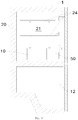
Fig. 5 , in an example of the present disclosure, the wall of therefrigerating compartment 21 is provided with a plurality of first steam holes 211 spaced apart from one another in the up-and-down direction. Thesteam conveying channel 40 is defined in therefrigerator body 20, thesteam conveying channel 40 has a plurality of second steam holes in communication with the plurality of first steam holes 211 in one-to-one correspondence. Specifically, thesteam conveying channel 40 is defined in the foaming layer of therefrigerator body 20 and in communication with thesteam outlet 1013 of thesteam generator 10 disposed to the upper surface of therefrigerator body 20. - Thus, the steam produced by the
steam generator 10 can be sprayed out through the plurality of first steam holes 211 almost simultaneously, such that the temperature in therefrigerating compartment 21 is rapidly raised to the sterilization temperature, and also the temperature in therefrigerating compartment 21 can be more uniform. - In another example of the present disclosure, the
steam conveying channel 40 is formed by the steam conveying tube, a first portion 411 of the steam conveying tube is disposed in thefoaming layer 23 of therefrigerator body 20 opposite to therefrigerating compartment 21, and the first portion 411 is provided with the plurality of second steam holes in communication with the plurality of first steam holes 211 in one-to-one correspondence. Specifically, the steam conveying tube is in communication with thesteam outlet 1013 of thesteam generator 10 disposed to the upper surface of therefrigerator body 20. - Thus, the steam produced by the
steam generator 10 can be sprayed out through the plurality of first steam holes 211 almost simultaneously, such that the temperature in therefrigerating compartment 21 is rapidly raised to the sterilization temperature, and also the temperature in therefrigerating compartment 21 can be more uniform. - Advantageously, a plurality of
racks 24 are disposed in therefrigerating compartment 21 and spaced apart from one another in the up-and-down direction (as illustrated inFig. 8 ), each space of a space betweenadjacent racks 24, a space between a bottom one of theracks 24 and a top wall of therefrigerating compartment 21, and a space between a top one of theracks 24 and the top wall of therefrigerating compartment 21 corresponds to at least one of the first steam holes 211. - As illustrated in
Figs. 6 to 10 , in a second embodiment of the present disclosure, thesteam generator 10 is disposed in therefrigerating compartment 21, and thesteam sterilization refrigerator 1 further includes thewater tank 50 disposed in therefrigerating compartment 21. Thewater tank 50 defines the water outlet, and the water outlet is hermetically connected to thewater inlet 1012 of thesteam generator 10. Thesteam outlet 1013 of thesteam generator 10 is in direct communication with therefrigerating compartment 21. - By disposing the
steam generator 10 in therefrigerating compartment 21, the steam can enter therefrigerating compartment 21 more rapidly, and also the temperature of the steam can be prevented from decreasing during conveying, such that therefrigerating compartment 21 can be sterilized more rapidly and effectively. Furthermore, by disposing thesteam generator 10 in therefrigerating compartment 21, thesteam conveying channel 40 or other components can be saved, such that the structure of thesteam sterilization refrigerator 1 can be simpler. - As illustrated in
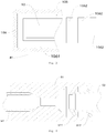
Fig. 10 , thesteam generator 10 includes afurnace body 101 and awater inlet tube 102, a first throughhole 1016 is defined in a wall of thefurnace body 101, and thewater inlet tube 102 is connected to the first throughhole 1016. As illustrated inFigs. 9 and 10 , thewater tank 50 includes awater tank body 501 and awater outlet tube 55, a second throughhole 502 is provided in a wall of thewater tank body 501, and thewater outlet tube 55 is connected to the second throughhole 502. A part of thewater inlet tube 102 is fitted in thewater outlet tube 55, and asealing ring 103 is disposed between the part of the water inlet tube and thewater outlet tube 55. Thus, the water in thewater tank 50 can be prevented from leaking through a gap between thewater inlet tube 102 and thewater outlet tube 55. - As illustrated in
Fig. 10 , an outer circumferential surface of the part of thewater inlet tube 102 is provided with afirst clamping rib 1021 and asecond clamping rib 1022 spaced apart from each other. A clamping slot is defined between thefirst clamping rib 1021 and thesecond clamping rib 1022, and thesealing ring 103 may be disposed in the clamping slot. Thus, the sealingring 103 can be mounted more stably, to prevent thesealing ring 103 from dislocation and to ensure a good sealing effect. - The part of the
water inlet tube 102 is detachably fitted in thewater outlet tube 55. That is to say, thesteam generator 10 is detachably mounted to thewater tank 50. Thus, when the water is to be added into thewater tank 50, thewater tank 50 can be detached from thesteam generator 10, such that thewater tank 50 can be taken out of therefrigerating compartment 21 and the water can be added into thewater tank 50 more conveniently. After the water injection is completed, thewater tank 50 can be placed back into therefrigerating compartment 21, and thewater tank 50 can be assembled with thesteam generator 10 again. - As illustrated in
Figs. 9 and 10 , thewater tank 50 further includes avalve disc 56, avalve stem 57 and anelastic element 58. Thevalve disc 56 is movable between a closed position where an inlet of thewater outlet tube 55 is closed and an open position where the inlet of thewater outlet tube 55 is open. In other words, when thevalve disc 56 is in the closed position, thevalve disc 56 can close thewater outlet tube 55, and when thevalve disc 56 is in the open position, thevalve disc 56 can be separated from thewater outlet tube 55 to open thewater outlet tube 55. The valve stem 57 is disposed in thewater outlet tube 55, and thevalve stem 57 is connected to thevalve disc 56. - When the
water inlet tube 102 is inserted into and fitted in thewater outlet tube 55, thevalve stem 57 is driven to move thevalve disc 56 from the closed position to the open position, such that thewater outlet tube 55 is communicated with thewater inlet tube 102 to supply the water in thewater tank 50 into thesteam generator 10. Theelastic element 58 is disposed between thevalve stem 57 and thewater outlet tube 55 and normally pushes thevalve stem 57 and thevalve disc 56 towards the closed position. - Thus, when the
water inlet tube 102 is not inserted into thewater outlet tube 55, since theelastic element 58 normally pushes thevalve stem 57 and thevalve disc 56 towards the closed position, thevalve disc 56 is in the closed position, and thewater outlet tube 55 is closed by thevalve disc 56, such that the water in thewater tank 50 can be prevent from leaking from thewater outlet tube 55. - While the
water inlet tube 102 is inserted into thewater outlet tube 55, thewater inlet tube 102 can drive thevalve stem 57 to move, and further thevalve stem 57 can drive thevalve disc 56 to move towards the open position to open thewater outlet tube 55, such that the water in thewater tank 50 can be supplied into thesteam generator 10 through thewater outlet tube 55 and thewater inlet tube 102. - As illustrated in
Figs. 9 and 10 , an end of thevalve stem 57 away from thevalve disc 56 may be provided with abaffle 571, and an inner wall of thewater outlet tube 55 may be provided with anannular rib 551. Theelastic element 58 is fitted over thevalve stem 57, and located between thebaffle 571 and therib 551. Thus, theelastic element 58 can be mounted more stably. Specifically, theelastic element 58 abuts against thebaffle 571 and therib 551. Theelastic element 58 maybe a spring. - As illustrated in
Fig. 10 , thewater inlet tube 102 may be disposed outside thefurnace body 101, and an end of thewater inlet tube 102 is fixed to an wall of thefurnace body 101; thewater outlet tube 55 may be disposed in thewater tank 50, and an end of thewater outlet tube 55 is opened and fixed to a wall of thewater tank 50. Thus, thesteam generator 10 and thewater tank 50 can have a more reasonable structure. - Advantageously, the wall of the
refrigerating compartment 21 is provided with a first limiting member, thewater tank 50 is provided with a second limitingmember 59 fitted with the first limiting member, and when the second limitingmember 59 is in contact with the first limiting member, thewater tank 50 is spaced apart from thesteam generator 10 at a preset distance. By spacing thewater tank 50 from thesteam generator 10 at the preset distance, thewater tank 50 can be prevented from being too close to thesteam generator 10, so as to prevent the high temperature of thesteam generator 10 from damaging thewater tank 50. - As illustrated in
Fig. 7 , thesteam sterilization refrigerator 1 further includes the plurality ofracks 24 and an airduct cover plate 60. The plurality ofracks 24 are disposed in therefrigerating compartment 21 and spaced apart from one another in the up-and-down direction, and thesteam generator 10 and thewater tank 50 are disposed between the bottom wall of therefrigerating compartment 21 and the bottom one of theracks 21. The airduct cover plate 60 is disposed in therefrigerating compartment 21 and located behind the plurality ofracks 24, and thesteam conveying channel 40 is defined between the airduct cover plate 60 and therefrigerating compartment 21. In other words, as illustrated inFig. 7 , a gas channel is defined between the airduct cover plate 60 and the wall of therefrigerating compartment 21, and the gas channel may be communicated with thesteam outlet 1013. - A plurality of steam holes 61 in communication with the
steam conveying channel 40 are provided in the airduct cover plate 60 and spaced apart from one another in the up-and-down direction, and each space of the space betweenadjacent racks 24 and the space between the top one of theracks 24 and the top wall of therefrigerating compartment 21 corresponds to at least one of the steam holes 61. That is to say, the space between adjacent racks corresponds to at least one of the steam holes 61, and the space between the top one of theracks 24 and the top wall of therefrigerating compartment 21 corresponds to at least one of the steam holes 61. - Thus, the steam produced by the
steam generator 10 can be sprayed out through the plurality of steam holes 61 almost simultaneously, such that the temperature in therefrigerating compartment 21 is rapidly raised to the sterilization temperature, and also the temperature in therefrigerating compartment 21 can be more uniform, that is, a temperature difference between the space betweenadjacent racks 24 and the space between the top one of theracks 24 and the top wall of therefrigerating compartment 21 can be minimized. - As illustrated in
Fig. 8 , thesteam sterilization refrigerator 1 further includes the plurality ofracks 24, the plurality ofracks 24 are disposed in therefrigerating compartment 21 and spaced apart from one another in the up-and-down direction, and thesteam generator 10 and thewater tank 50 are disposed between the bottom wall of therefrigerating compartment 21 and the bottom one of theracks 21. Thesteam conveying channel 40 is formed by thesteam conveying tube 41, thesteam conveying tube 41 is disposed in therefrigerating compartment 21, a lower port of thesteam conveying tube 41 is in communication with thesteam outlet 1013, and the plurality of steam holes 61 are provided in thesteam conveying tube 41 and spaced apart from one another in the up-and-down direction. - Each space of the space between
adjacent racks 24 and the space between the top one of theracks 24 and the top wall of therefrigerating compartment 21 corresponds to at least one of the steam holes 61. That is to say, the space between adjacent racks corresponds to at least one of the steam holes 61, and the space between the top one of theracks 24 and the top wall of therefrigerating compartment 21 corresponds to at least one of the steam holes 61. - Thus, the steam produced by the
steam generator 10 can be sprayed out through the plurality of steam holes 61 almost simultaneously, such that the temperature in therefrigerating compartment 21 is rapidly raised to the sterilization temperature, and also the temperature in therefrigerating compartment 21 can be more uniform, that is, the temperature difference between the space betweenadjacent racks 24 and the space between the top one of theracks 24 and the top wall of therefrigerating compartment 21 can be minimized. - Specifically, as illustrated in
Fig. 8 , thesteam conveying tube 41 is L-shaped, a horizontal limb of thesteam conveying tube 41 is connected to thesteam outlet 22, and the plurality of steam holes 61 may be disposed to a vertical limb of thesteam conveying tube 41. Areas of respective openings of the plurality of steam holes 61 can be decreased from bottom to top. The temperature difference between the space betweenadjacent racks 24 and the space between the top one of theracks 24 and the top wall of therefrigerating compartment 21 can be further reduced. - As illustrated in
Figs. 11 to 13 , in a third embodiment of the present disclosure, thesteam sterilization refrigerator 1 further includes astorage box 71 disposed in therefrigerating compartment 21 and capable of being pushed into and pulled out of therefrigerating compartment 21. Thestorage box 71 defines astorage chamber 711 adapted to accommodate the water and articles, thestorage chamber 711 is in communication with thewater inlet 1012 of thesteam generator 10 to supply the water in thestorage chamber 711 into thesteam generator 10. - When the
steam sterilization refrigerator 1 is in normal operation, thestorage box 71 can be used to accommodate articles (such as food), but when thesteam sterilization refrigerator 1 needs to be sterilized, the articles in the refrigerating compartment 21 (including the articles in the storage box 71) can be taken out, and the water for producing the steam can be filled into thestorage box 71. That is to say, thestorage box 71 integrates functions of storing articles and storing the water, and when thesteam sterilization refrigerator 1 needs to be sterilized, thestorage box 71 serves as the water tank for supplying the water into thesteam generator 10. - Since the
storage box 71 integrates the functions of storing articles and storing the water, there is no need to provide a separate water tank for supplying the water to thesteam generator 10. By communicating thestorage chamber 711 of thestorage box 71 with thewater inlet 1012 of thesteam generator 10, there is no need to provide the separate water tank for supplying the water to thesteam generator 10, thereby reducing the manufacturing cost of thesteam sterilization refrigerator 1. - As illustrated in
Figs. 11 to 13 , thesteam sterilization refrigerator 1 further includes a waterinlet transition member 72, a firstwater inlet tube 73 and a secondwater inlet tube 74. The waterinlet transition member 72 is disposed in therefrigerating compartment 21, the waterinlet transition member 72 defines awater flow channel 721 therein, and thewater flow channel 721 has aninlet 7211 and anoutlet 7212. The firstwater inlet tube 73 is disposed to thestorage box 71, a first end of the firstwater inlet tube 73 is in communication with thestorage chamber 711, and a second end of the firstwater inlet tube 73 is connected to theinlet 7211 of the waterinlet transition member 72 when thestorage box 71 is located in therefrigerating compartment 21. A first end of the secondwater inlet tube 74 is connected to theoutlet 7212 of the waterinlet transition member 72, and a second end of the secondwater inlet tube 74 is in communication with thewater inlet 1012 of thesteam generator 10. - Thus, the water in the
storage chamber 711 can be conveyed into thesteam generator 10 passing through the firstwater inlet tube 73, the waterinlet transition member 72 and the secondwater inlet tube 74 sequentially. By disposing the waterinlet transition member 72 between thestorage box 71 and thesteam generator 10, thestorage box 71 can be communicated with thesteam generator 10 more conveniently and easily, and also the reliability of connection between thestorage box 71 and thesteam generator 10 can be ensured. When thestorage box 71 is pulled out of therefrigerating compartment 21, thestorage box 71 is disconnected from thesteam generator 10, thereby facilitating the assembly and disassembly thereof. - Specifically, the water
inlet transition member 72 may be disposed to a rear wall surface of therefrigerating compartment 21, the first end of the first water inlet tube 31 extends into a bottom of thestorage chamber 711, the second end of the firstwater inlet tube 73 extends into thewater flow channel 721 via theinlet 7211, and the first end of the secondwater inlet tube 74 extends into thewater flow channel 721 via theoutlet 7212. When thestorage box 71 is pulled out of therefrigerating compartment 21, the second end of the firstwater inlet tube 73 is separated from thewater flow channel 721, and thestorage box 71 is no longer communicated with thesteam generator 10. When thestorage box 71 is pushed into therefrigerating compartment 21, the second end of the firstwater inlet tube 73 extends into thewater flow channel 721 via theinlet 7211 again, and in this case thestorage box 71 is communicated with thesteam generator 10. - As illustrated in
Fig. 11 , advantageously, the first end of the firstwater inlet tube 73 is provided with afilter 75. Thus, impurities in the water of thestorage box 71 can be prevented from entering the waterinlet transition member 72 and thesteam generator 10, so as to avoid blockage. Moreover, by disposing thefilter 75 to the first end of the firstwater inlet tube 73, cleanness of the waterinlet transition member 72 and thesteam generator 10 can be ensured, and cleaning difficulty and frequency can be reduced, thereby facilitating extension of a service life of thesteam generator 10. - As illustrated in
Figs. 14 to 15 , in a fourth embodiment of the present disclosure, thesteam sterilization refrigerator 1 further includes anair duct component 91, anevaporator 92 and afan 93. A ventilatingchannel 911 is defined in theair duct component 91, or the ventilatingchannel 911 is defined between theair duct component 91 and the wall of therefrigerating compartment 21. The ventilatingchannel 911 is in communication with each of therefrigerating compartment 21 and thesteam outlet 1013, and thesteam conveying channel 40 is formed by the ventilatingchannel 911. Theevaporator 92 is disposed in the ventilatingchannel 911, and thefan 93 is disposed in the ventilatingchannel 911 to convey the steam and cold air into therefrigerating compartment 21. - That is to say, the
steam sterilization refrigerator 1 is an air-cooled refrigerator, and theair duct component 91 constitutes an air channel of the air-cooled refrigerator. In other words, the air-cooled refrigerator conveys the steam into therefrigerating compartment 21 by means of the air channel. Specifically, when thesteam sterilization refrigerator 1 refrigerates, thefan 93 is configured to convey the cold air cooled by theevaporator 92 into therefrigerating compartment 21; when thesteam sterilization refrigerator 1 is sterilized, thefan 93 is configured to convey the steam produced by thesteam generator 10 into therefrigerating compartment 21. In other words, thesteam sterilization refrigerator 1 does not need to be provided with an additional fan. - When the known sterilization refrigerator is the air-cooled refrigerator, it needs to be provided with the additional fan to suck the air in the refrigerating compartment into the air hose, and to blow the sterile air in the air hose into the refrigerating compartment. That is to say, when the known sterilization refrigerator is the air-cooled refrigerator, it needs to be provided with at least two fans, one fan is configured to convey the cold air into the refrigerating compartment, and the other fan is configured to suck the air in the refrigerating compartment into the air hose and to blow the sterile air in the air hose into the refrigerating compartment.
- The
steam sterilization refrigerator 1 according to embodiments of the present disclosure conveys the steam by utilizing the air channel existing in the air-cooled refrigerator, such that there is no need to additionally provide any component configured to convey the steam, and there is no need to greatly reconstruct a production line of the existing air-cooled refrigerator. Moreover, since the high-temperature steam produced by thesteam generator 10 enters the ventilatingchannel 911 and theevaporator 92 is located in the ventilatingchannel 911, theevaporator 92 can be defrosted by utilizing the high-temperature steam. That is to say, while thesteam sterilization refrigerator 1 is being sterilized, theevaporator 92 can also be defrosted. - Advantageously, as illustrated in
Fig. 14 , thesteam generator 10 may be disposed in thecompressor chamber 22 to facilitate a purpose of achieving rapid heat dissipation. - As illustrated in
Fig. 14 , therefrigerator body 20 has a refrigeratingchamber 213 and a freezingchamber 214 therein, the ventilatingchannel 911 is in communication with each of the refrigeratingchamber 213, the freezingchamber 214 and thesteam outlet 1013. Specifically, the ventilatingchannel 911 includes a freezing air duct disposed in a freezing liner, a refrigerating air duct configured to convey the cold air and the steam to the refrigeratingchamber 213, and an air return channel configured to return the cold air in the refrigeratingchamber 213 into the freezingchamber 214. In other words, the freezing air duct is disposed in the freezingchamber 214, i.e. the freezingchamber 214 includes a mounting space configured to place the freezing air duct and a freezing space configured to store articles. - As illustrated in
Fig. 14 , thesteam sterilization refrigerator 1 further includes asteam connecting tube 94, a first end of thesteam connecting tube 94 is connected to thesteam outlet 1013, a second end of thesteam connecting tube 94 extends into the ventilatingchannel 911, and an opening of the second end of thesteam connecting tube 94 faces towards theevaporator 92. Thus, the high-temperature steam sprayed out of the opening of the second end of thesteam connecting tube 94 can be directly sprayed to theevaporator 92, so as to prevent the high-temperature steam from directly spraying to components of thesteam sterilization refrigerator 1 made of nonmetallic materials. - Since the
evaporator 92 of thesteam sterilization refrigerator 1 is a metal member, theevaporator 92 can bear a certain high-temperature impact. By making the opening of the second end of thesteam connecting tube 94 face theevaporator 92, the high-temperature steam sprayed out of the opening of the second end of thesteam connecting tube 94 can be prevented from damaging the components of thesteam sterilization refrigerator 1 made of nonmetallic materials. Thus, the service life and the reliability of thesteam sterilization refrigerator 1 can be prevented from being influenced, a defrosting effect can be further improved, and a refrigerating effect of thesteam sterilization refrigerator 1 can be ensured. - Advantageously, the second end of the
steam connecting tube 94 is adj acent to theevaporator 92. More advantageously, the second end of thesteam connecting tube 94 is opposite to theevaporator 92. - As illustrated in
Figs. 16 and17 , in a fifth embodiment of the present disclosure, thesteam generator 10 includes thefurnace body 101 and anelectric heater 104, thefurnace body 101 defines theaccommodating cavity 1011 configured to accommodate the water, and theaccommodating cavity 1011 defines thewater inlet 1012 and thesteam outlet 1013. Theelectric heater 104 is adapted to be connected to a power source through apower cord 95 to produce the heat. - The
steam sterilization refrigerator 1 further includes the conveyingpump 53, atemperature control protector 81, atemperature sensor 82 and acontroller 83. The water outlet of the conveyingpump 53 is in communication with thewater inlet 1012 of thesteam generator 10. Thetemperature control protector 81 is disposed to an outer surface of thefurnace body 101 and configured to sense a temperature of the outer surface of thefurnace body 101. Thetemperature control protector 81 is connected to thepower cord 95 and automatically disconnected from thepower cord 95 when the temperature of the outer surface of thefurnace body 101 is greater than or equal to a preset temperature. Thetemperature sensor 82 is disposed to the outer surface of thefurnace body 101 and configured to sense the temperature of the outer surface of thefurnace body 101. Thecontroller 83 is connected to thetemperature sensor 82 and theelectric heater 104, and controls theelectric heater 104 to stop heating when the temperature of the outer surface of thefurnace body 101 is greater than or equal to the preset temperature. - During the operation of the
steam sterilization refrigerator 1, the temperature of thefurnace body 101 is maintained within a stable temperature value range according to the sterilization temperature, the power of theelectric heater 104, the water flow rate, or other factors. In the case where the sterilization temperature and the power of theelectric heater 104 are definite, variation of the water flow rate will lead to an abnormal increase in the temperature of thefurnace body 101. Thetemperature control protector 81 is configured to sense the temperature of the outer surface of thefurnace body 101, and thetemperature sensor 82 is configured to measure the temperature of the outer surface of thefurnace body 101. - Specifically, when the temperature of the outer surface of the
furnace body 101 is smaller than the preset temperature, thetemperature control protector 81 is turned on to communicate theelectric heater 104 and the power source, and in this case thesteam sterilization refrigerator 1 operates normally. When the temperature of the outer surface of thefurnace body 101 is greater than or equal to the preset temperature, thetemperature control protector 81 is turned off automatically to disconnect theelectric heater 104 from the power source, and in this case thesteam sterilization refrigerator 1 stops operating. - The
temperature sensor 82 measures the temperature of the outer surface of thefurnace body 101 in real time, and the measured temperature value of thetemperature sensor 82 is fed back to thecontroller 83 in real time. Specifically, when the measured temperature value of thetemperature sensor 82 is smaller than the preset temperature (i.e. when the temperature of the outer surface of thefurnace body 101 is smaller than the preset temperature), thecontroller 83 controls theelectric heater 104 to communicate with the power source, such that thesteam generator 10 can operate normally. When the measured temperature value of thetemperature sensor 82 is greater than or equal to the preset temperature (i.e. when the temperature of the outer surface of thefurnace body 101 is greater than or equal to the preset temperature), thecontroller 83 controls theelectric heater 104 to disconnect from the power source, such that thesteam generator 104 can stop heating. - In the
steam sterilization refrigerator 1 according to embodiments of the present disclosure, by disposing thetemperature control protector 81 andtemperature sensor 82 to the outer surface of thefurnace body 101, a dual dry heating-resistant protection can be formed, such that even if one of thetemperature control protector 81 and thetemperature sensor 82 malfunctions, the other of thetemperature control protector 81 and thetemperature sensor 82 still can be used for protection. Thus, the safety performance of thesteam generator 10 can be significantly improved, and further the safety performance of thesteam sterilization refrigerator 1 can be improved. - Specifically, the
temperature control protector 102 is a mechanical temperature controller, such as a temperature control tripping protector. When the temperature of the outer surface of thefurnace body 101 is greater than or equal to the preset temperature, the temperature control tripping protector trips automatically to disconnect theelectric heater 104 from the power source, thereby cutting off the power supply to theelectric heater 104. - As illustrated in
Fig. 17 , thesteam sterilization refrigerator 1 further includes arelay 85, therelay 85 is connected to thepower cord 95, and thecontroller 83 is connected to therelay 85 to control the communication and disconnection of theelectric heater 104 and the power source through therelay 85. Thus, thecontroller 83 can control the communication and disconnection of theelectric heater 104 and the power source through therelay 85. - Specifically, when the measured temperature value of the
temperature sensor 82 is smaller than the preset temperature, thecontroller 83 control therelay 85 to turn on to communicate theelectric heater 104 and the power source, in which case theelectric heater 104 operates normally. When the measured temperature value of thetemperature sensor 82 is greater than or equal to the preset temperature, thecontroller 83 control therelay 85 to turn off to disconnect theelectric heater 104 from the power source, in which case theelectric heater 104 stops heating. - Advantageously, the
controller 83 is connected to an electric motor of the conveyingpump 53 so as to monitor a working current of the electric motor of the conveyingpump 53. Thecontroller 83 can monitor the working current of the electric motor of the conveyingpump 53 by means of a known method for monitoring a current. By utilizing thecontroller 83 to monitor the working current of the electric motor of the conveyingpump 53, a failure mode that possibly occurs, such as conveying pump abnormality, a water shortage in the water tank, pipeline clogging, and so on, can be prejudged depending on the working current of the electric motor of the conveyingpump 53. - Specifically, when the working current of the electric motor of the conveying
pump 53 is within the preset range, and the temperature of the outer surface of thefurnace body 101 increases abnormally (theelectric heater 104 is disconnected from the power source), this means that the water of thewater tank 50 is insufficient or the conveyingpump 53 is abnormal (that is, the water output by the conveyingpump 53 does not flow into the water tank 50). When the working current of the electric motor of the conveyingpump 53 exceeds the preset range, and the temperature of the outer surface of thefurnace body 101 increases abnormally (theelectric heater 104 is disconnected from the power source), this means that the pipeline is clogged. - The preset range (normal range) may be a range formed by a no-load current and a full-load current of the electric motor of the conveying
pump 53. In other words, the working current of the electric motor of the conveyingpump 53 is greater than or equal to the no-load current of the electric motor of the conveyingpump 53 and smaller than or equal to the full-load current of the electric motor of the conveyingpump 53, the working current of the electric motor of the conveyingpump 53 being within the preset range. - The
steam sterilization refrigerator 1 further includes afirst indicator light 841 and asecond indicator light 842, and the each of thefirst indicator light 841 and thesecond indicator light 842 is connected to thecontroller 83. When the working current of the electric motor of the conveyingpump 53 is within the preset range and theelectric heater 104 stops heating (the temperature of the outer surface of thefurnace body 101 increases abnormally, and theelectric heater 104 is disconnected from the power source), thecontroller 83 controls thefirst indicator light 841 to glow or flicker; when the working current of the electric motor of the conveyingpump 53 exceeds the preset range and the electric heater stops heating (the temperature of the outer surface of thefurnace body 101 increases abnormally, and theelectric heater 104 is disconnected from the power source), thecontroller 83 controls thesecond indicator light 842 to glow or flicker. Thus, the user can determine the failure reason of thesteam generator 10 by observing thefirst indicator light 841 and/or thesecond indicator light 842. - In another example of the present disclosure, the
steam sterilization refrigerator 1 further includes avoice reminder 86, and thevoice reminder 86 is connected to thecontroller 83. When the working current of the electric motor of the conveyingpump 53 is within the preset range and theelectric heater 104 stops heating, thecontroller 83 controls thevoice reminder 86 to give out a first reminding voice; when the working current of the electric motor of the conveyingpump 53 exceeds the preset range and the electric heater stops heating, thecontroller 83 controls thevoice reminder 86 to give out a second reminding voice. Thus, the user can determine the failure reason of thesteam generator 10 by listening to the first reminding voice and/or the second reminding voice given out by thevoice reminder 86. - As illustrated in
Figs. 18 to 21 , in a sixth embodiment of the present disclosure, thesteam sterilization refrigerator 1 further includes awater level gauge 87 configured to detect a water level in thewater tank 50, a water-shortage indicator light 88, a full-water indicator light 89 and thecontroller 83. The water-shortage indicator light 88 and the full-water indicator light 89 are disposed in therefrigerating compartment 21. Thecontroller 83 is connected to each of thewater level gauge 87, the water-shortage indicator light 88, the full-water indicator light 89 and thesteam generator 10 separately. When a water level detection value of thewater level gauge 87 is smaller than a first preset value, thecontroller 83 controls the water-shortage indicator light 88 to glow or flicker, and when the water level detection value is greater than a second preset value, thecontroller 83 controls the full-water indicator light 89 to light or flicker. The first preset value is smaller than the second preset value. - The water level of the
water tank 50 can be detected by thewater level gauge 87 before thesteam sterilization refrigerator 1 is sterilized. If the full-water indicator light 89 does not glow or flicker, this indicates that thewater tank 50 is not full of the water, and the water can be added into thewater tank 50 until the full-water indicator light 89 glows or flickers. Thus, thesteam generator 10 can be restarted after thewater tank 50 is full of the water, such that a dry heating phenomenon can be prevented during the operation of thesteam generator 10. - Moreover, when the
steam generator 10 continuously produces the steam, the water in thewater tank 50 is continuously supplied into thesteam generator 10, that is, the water level of thewater tank 50 descends continuously. When thewater level gauge 87 detects that the water level of thewater tank 50 is lower than the first preset value, thecontroller 83 controls thesteam generator 10 to stop operating, and controls the water-shortage indicator light 88 to glow or flicker, to avoid the dry heating of thesteam generator 10, such that the safety of thesteam generator 10 can be improved. After opening thedoor body 30 of thesteam sterilization refrigerator 1, the user will see that the water-shortage indicator light 88 is glowing or flickering, such that the user may understand that the reason why thesteam generator 10 stops operating is that the water level of thewater tank 50 is lower than the first preset value. - Specifically, the
water level gauge 87 may be a magnetic water level gauge, and the magnetic water level gauge can measure the water level of thewater tank 50 accurately, and the magnetic water level gauge is sensitive. - As illustrated in
Fig. 1 , thesteam sterilization refrigerator 1 further includes a water level indicating mechanism 27 configured to indicate the water level of thewater tank 50. Specifically, an opening is provided in a side wall of thewater tank 50, a lower edge of the opening is flush with an inner bottom surface of thewater tank 50, a water level indicating mechanism 27 includes an indicating tube, and a lower end of the indicating tube is connected to the opening. In addition, the water level indicating mechanism 27 includes an indicating slot provided in the side wall of thewater tank 50 and a transparent member hermetically covering the indicating slot. - In an embodiment of the present disclosure, the water level indicating mechanism 27 includes a
U-shaped tube 271 and an opening 272 provided in the bottom of thewater tank 50, an end of theU-shaped tube 271 is in communication with the opening 272 of thewater tank 50, and the other end of theU-shaped tube 271 is higher than a top end of thewater tank 50 or is flush with the top end of thewater tank 50. - As illustrated in
Figs. 19 and 20 , thesteam sterilization refrigerator 1 may include awater feed tube 25 and awater feed funnel 26, a lower end of thewater feed tube 25 is in communication with thewater tank 50, and thewater feed funnel 26 is disposed to an upper end of thewater feed tube 25. When the water is fed into thewater tank 50, the water can be fed into thewater feed funnel 26, and then the water enters thewater tank 50 through thewater feed tube 25. By providing thewater feed tube 25 in communication with thewater tank 50 and disposing thewater feed funnel 26 to thewater feed tube 25, the water can be fed into thewater tank 50 conveniently and easily. - As illustrated in
Fig. 20 , an upper part of thewater feed tube 25 is located in the foaming layer of therefrigerator body 20, thewater feed funnel 26 is disposed to the upper end of thewater feed tube 25 and is pivotable between an initial position and a water feed position. In the initial position, an outer wall surface of thewater feed funnel 26 is flush with awall 215 of therefrigerating compartment 21, and in the water feed position, at least a part of thewater feed funnel 26 protrudes from thewall 215 of therefrigerating compartment 21. When the water needs to be fed into thewater tank 50, thewater feed funnel 26 can be pivoted from the initial position to the water feed position. When the water feed is completed, thewater feed funnel 26 can be pivoted from the water feed position to the initial position. Thus, the space of therefrigerating compartment 21 can be saved, that is, a storage space of therefrigerating compartment 21 can be increased, and also thesteam sterilization refrigerator 1 can be more artistic. - Advantageously, as illustrated in
Fig. 20 , agroove 2151 is provided in thewall 215 of therefrigerating compartment 21, and in the initial position, thewater feed funnel 26 is accommodated in thegroove 2151. Thus, thesteam sterilization refrigerator 1 can have a more reasonable structure. - A control method for a steam sterilization refrigerator according to embodiments of the present disclosure will be described below with reference to
Figs. 22 to 24 . The steam sterilization refrigerator according to embodiments of the present disclosure includes a refrigerator body defining a refrigerating compartment therein, a compressor and a steam generator. Specifically, the steam sterilization refrigerator according to embodiments of the present disclosure may be thesteam sterilization refrigerator 1 according to the above embodiments. - The control method for the steam sterilization refrigerator according to embodiments of the present disclosure includes the following steps: controlling the steam generator to operate to supply steam to the refrigerating compartment; detecting a temperature in the refrigerating compartment, and starting timing when a detected temperature value reaches a first preset value; and controlling the steam generator to stop when the timing reaches a first preset time.
- In the control method for the steam sterilization refrigerator according to embodiments of the present disclosure, by conveying the steam produced by the steam generator into the refrigerating compartment, the air in the refrigerating compartment can be sterilized, and also bacteria on the wall of the refrigerating compartment and bacteria attached to accessories (such as a storage box and a rack) in the refrigerating compartment can be killed, so as to make the refrigerating compartment cleaner and more hygienic, such that the requirements of the user can be better satisfied.
- Advantageously, the first preset value is 60 degrees Celsius to 80 degrees Celsius. That is to say, when the temperature in the
refrigerating compartment 21reaches 60 degrees Celsius to 80 degrees Celsius, thecontroller 83 starts initial timing to compute the sterilization time. More preferably, the first preset value is 60 degrees Celsius to 70 degrees Celsius. Most preferably, the first preset value is 60 degrees Celsius. Thus, the energy consumption of thesteam sterilization refrigerator 1 can be reduced in a case where the sterilizing effect is ensured. - As illustrated in
Fig. 23 , when the timing (i.e. the initial timing) reaches the first preset time, thecontroller 83 controls thesteam generator 10 to stop. For example, thecontroller 83 controls thesteam generator 10 to stop through therelay 85, that is, thecontroller 83 controls thesteam generator 10 to disconnect from the power source through therelay 85. So far, the sterilization process of thesteam sterilization refrigerator 1 is completed. - Advantageously, the first preset time is 10-40 minutes. That is to say, after the temperature in the
refrigerating compartment 21 reaches the first preset value, the refrigeratingcompartment 21 is sterilized for 10-40 minutes. - More preferably, the first preset time is 20-30 minutes. Most preferably, the first preset time is 25 minutes. Thus, in the case where the sterilizing effect is ensured, the energy consumption of the
steam sterilization refrigerator 1 can be reduced, and the sterilization time of therefrigerating compartment 21 can be shortened as much as possible, so as to be user-friendly. - As illustrated in
Fig. 23 , in an embodiment of the present disclosure, the control method further includes comparing the detected temperature value with the first preset value, before the timing reaches the first preset time. In other words, the detected temperature value is compared with the first preset value, before the sterilization of therefrigerating compartment 21 is completed. When the detected temperature value is greater than the first preset value, the steam generator is controlled to stop after a delay of a second preset time; and when the detected temperature value is smaller than or equal to the first preset value, the steam generator is controlled to operate. - Advantageously, the control method for the steam sterilization refrigerator according to embodiments of the present disclosure further includes: comparing the detected temperature value with the first preset value before the timing reaches the first preset time; when the detected temperature value is greater than the first preset value, controlling the
steam generator 10 to stop after the delay of the second preset time; and when the detected temperature value is smaller than or equal to the first preset value, controlling the steam generator to operate, and after a delay of a fourth preset time, comparing the detected temperature value with the first preset value again. - Specifically, when the steam produced by the
steam generator 10 enters therefrigerating compartment 21 continuously, the temperature in therefrigerating compartment 21 increases continuously. When the temperature in therefrigerating compartment 21 reaches the first preset value, thecontroller 83 starts the initial timing to compute the sterilization time. Sequentially, the temperature in therefrigerating compartment 21 is greater than the first preset value, that is, the temperature detection value of the temperature detector is greater than the first preset value, and after the delay of the second preset time, thecontroller 83 controls thesteam generator 10 to stop, such that the steam is no longer conveyed into therefrigerating compartment 21. - Due to a heat exchange effect, the temperature in the
refrigerating compartment 21 will drop slowly after the steam is no longer conveyed into therefrigerating compartment 21. When the temperature in therefrigerating compartment 21 is smaller than or equal to the first preset value, thecontroller 83 controls thesteam generator 10 to operate, such that the steam is conveyed into therefrigerating compartment 21 again. - After the delay of the fourth preset time, the temperature detection value of the temperature detector is compared with the first preset value again. If the temperature in the
refrigerating compartment 21 is greater than the first preset value, after the delay of the second preset time, thecontroller 83 controls thesteam generator 10 to stop. If the temperature in therefrigerating compartment 21 is still smaller than or equal to the first preset value, after the delay of the fourth preset time, the temperature detection value of the temperature detector is compared with the first preset value again, until the temperature in therefrigerating compartment 21 is greater than the first preset value. After the timing (the sterilization time) reaches the first preset time, the temperature detection value of the temperature detector is no longer compared with the first preset value. - Thus, during the sterilization process, the
steam generator 10 does not need to operate all the time, and hence the energy consumption of thesteam sterilization refrigerator 1 can be reduced in the case where the sterilizing effect is ensured. Moreover, by delaying the turn-off of thesteam generator 10, thesteam generator 10 can be prevented from being turned on and off frequently, such that thesteam generator 10 can be prevented from damage, so as to prolong the service life of thesteam generator 10. - Advantageously, the second preset time is 1-3 minutes, and the fourth preset time is 1-3 minutes. More advantageously, the second preset time is 2 minutes, and the fourth preset time is 2 minutes.
- In another example of the present disclosure, the control method for the steam sterilization refrigerator according to embodiments of the present disclosure further includes: comparing the temperature in the
refrigerating compartment 21 with the first preset value before the timing reaches the first preset time; when the temperature in therefrigerating compartment 21 is greater than the first preset value, controlling thesteam generator 10 to stop, and when the temperature in therefrigerating compartment 21 is smaller than or equal to the third preset value, controlling the steam generator to operate, in which the third preset value is smaller than the first preset value. - Thus, during the sterilization process, the
steam generator 10 does not need to operate all the time, and hence the energy consumption of thesteam sterilization refrigerator 1 can be reduced in the case where the sterilizing effect is ensured. Moreover, thesteam generator 10 can be prevented from being turned on and off frequently, such that thesteam generator 10 can be prevented from damage, so as to prolong the service life of thesteam generator 10. Advantageously, the third preset value is 55 degrees Celsius to 65 degrees Celsius. - As illustrated in
Fig. 24 , advantageously, the control method for the steam sterilization refrigerator according to embodiments of the present disclosure further includes: detecting a temperature of thesteam generator 10, and controlling thesteam generator 10 to stop when the temperature of thesteam generator 10 reaches the second preset value. Thus, thesteam generator 10 can be prevented from the dry heating, and the temperature of thesteam generator 10 can be prevented from being too high, such that the safety performance of thesteam generator 10 can be significantly improved, and further the safety performance of thesteam sterilization refrigerator 1 can be improved. - The second preset value is 160 degrees Celsius to 200 degrees Celsius. Advantageously, the second preset value is 170 degrees Celsius to 190 degrees Celsius. More advantageously, the second preset value is 180 degrees Celsius.
- In a specific example of the present disclosure, when the
steam generator 10 starts to operate, there is no water in thesteam generator 10. The water is supplied to thesteam generator 10 when the temperature of thesteam generator 10reaches 50 degrees Celsius to 80 degrees Celsius. Thus, thesteam generator 10 can produce the steam with higher temperature, the sterilizing effect can be further improved, and the sterilization time can be further shortened. - Advantageously, the water is supplied into the
steam generator 10 at a flow rate of 30 ml/min to 40 ml/min. Thus, a phenomenon of hot water splashing in thesteam generator 10 can be prevented. - In a specific example of the present disclosure, after the
steam generator 10 is controlled to supply the steam to therefrigerating compartment 21 for the third preset time, and the temperature in therefrigerating compartment 21 is smaller than the first preset value, thesteam generator 10 is controlled to stop. - When the
steam generator 10 starts to operate (that is the sterilization is started), the user may forget to close thedoor body 30 or thedoor body 30 is not closed tightly, in which case the steam entering therefrigerating compartment 21 may leak to the environment, such that the temperature in therefrigerating compartment 21 cannot be raised. If the temperature in therefrigerating compartment 21 is smaller than the first preset value after the third preset time, thesteam generator 10 is controlled to stop, such that the steam produced by thesteam generator 10 can be prevented from leakage, and also the user can be reminded to close thedoor body 30 or close thedoor body 30 tightly. - Advantageously, the third preset time is 35-45 minutes.
- In the specification, it is to be understood that terms such as "central," "longitudinal," "lateral," "length," "width," "thickness," "upper," "lower," "front," "rear," "left," "right," "vertical," "horizontal," "top," "bottom," "inner," "outer," "clockwise," "counterclockwise," "axial," "radial" and "circumferential" should be construed to refer to the orientation as then described or as shown in the drawings under discussion. These relative terms are for convenience of description and do not require that the present disclosure be constructed or operated in a particular orientation.
- In addition, terms such as "first" and "second" are used herein for purposes of description and are not intended to indicate or imply relative importance or significance. Thus, the feature defined with "first" and "second" may comprise one or more of this feature. In the description of the present disclosure, "a plurality of' means two or more than two, unless specified otherwise.
- In the present disclosure, unless specified or limited otherwise, the terms "mounted," "connected," "coupled," "fixed" and the like are used broadly, and may be, for example, fixed connections, detachable connections, or integral connections; may also be mechanical or electrical connections; may also be direct connections or indirect connections via intervening structures; may also be inner communications of two elements. The above terms can be understood by those skilled in the art according to specific situations.
- In the present disclosure, unless specified or limited otherwise, a structure in which a first feature is "on" or "below" a second feature may include an embodiment in which the first feature is in direct contact with the second feature, and may also include an embodiment in which the first feature and the second feature are not in direct contact with each other, but are contacted via an additional feature formed therebetween. Furthermore, a first feature "on," "above," or "on top of" a second feature may include an embodiment in which the first feature is right or obliquely "on," "above," or "on top of" the second feature, or just means that the first feature is at a height higher than that of the second feature. While a first feature "below," "under," or "on bottom of" a second feature may include an embodiment in which the first feature is right or obliquely "below," "under," or "on bottom of" the second feature, or just means that the first feature is at a height lower than that of the second feature.
- Reference throughout this specification to "an embodiment," "some embodiments," "an example," "a specific example," or "some examples," means that a particular feature, structure, material, or characteristic described in connection with the embodiment or example is included in at least one embodiment or example of the present disclosure. Thus, the appearances of the phrases in various places throughout this specification are not necessarily referring to the same embodiment or example of the present disclosure. Furthermore, the particular features, structures, materials, or characteristics may be combined in any suitable manner in one or more embodiments or examples. In addition, without conflicting, various embodiments or examples or features of various embodiments or examples described in the present specification may be combined by those skilled in the art.
- Although explanatory embodiments have been shown and described, it would be appreciated by those skilled in the art that the above embodiments cannot be construed to limit the present disclosure, and changes, alternatives, and modifications can be made in the embodiments without departing from spirit, principles and scope of the present disclosure.
Claims (30)
- A steam sterilization refrigerator, comprising:a refrigerator body having a refrigerating compartment and a compressor chamber therein;a door body disposed to the refrigerator body; anda steam generator disposed to at least one of the refrigerator body and the door body, the steam generator having a steam outlet, and the steam outlet being in direct communication with the refrigerating compartment or in indirect communication with the refrigerating compartment via a steam conveying channel.
- The steam sterilization refrigerator according to claim 1, wherein the steam generator is disposed in the compressor chamber, a first side of the steam generator is provided with an inserting part connected to the refrigerator body in an inserting manner, a second side of the steam generator opposite to the first side is provided with a connecting part, and the connecting part is connected to the refrigerator body.
- The steam sterilization refrigerator according to claim 1, wherein the steam generator is disposed to one of an upper surface, a left surface, a right surface and a rear surface of the refrigerator body, the steam conveying channel is formed by a steam conveying tube, a first end of the steam conveying tube is connected to the steam outlet, and a second end of the steam conveying tube penetrates a foaming layer of the refrigerator body and extends into the refrigerating compartment or is flush with a wall of the refrigerating compartment.
- The steam sterilization refrigerator according to any one of claims 1-3, further comprising:a water tank detachably disposed to an upper surface of the refrigerator body;a flexible connecting tube;a first connecting tube having a first end connected to the water tank, and a second end detachably fitted in a first end of the flexible connecting tube;a conveying pump having a water outlet in communication with a water inlet of the steam generator; anda second connecting tube having a first end fitted in a second end of the flexible connecting tube, and a second end connected to a water inlet of the conveying pump.
- The steam sterilization refrigerator according to claim 4, wherein an inner circumferential wall of the first end of the flexible connecting tube is provided with a first annular sealing flange and a second annular sealing flange, when the second end of the first connecting tube is fitted in the first end of the flexible connecting tube, an end surface of the second end of the first connecting tube abuts against the first annular sealing flange, and the second annular sealing flange abuts against a circumferential surface of the first connecting tube.
- The steam sterilization refrigerator according to any one of claims 1 to 5, wherein a plurality of first steam holes are provided in a wall of the refrigerating compartment and spaced apart in an up-and-down direction, and the steam conveying channel is formed in the refrigerator body and has a plurality of second steam holes in communication with the plurality of first steam holes in one-to-one correspondence.
- The steam sterilization refrigerator according to any one of claims 1 to 5, wherein the steam conveying channel is formed by a steam conveying tube, a first portion of the steam conveying tube is disposed in a foaming layer of the refrigerator body opposite to the refrigerating compartment, and the first portion of the steam conveying tube is provided with a plurality of second steam holes in communication with a plurality of first steam holes in one-to-one correspondence.
- The steam sterilization refrigerator according to claim 1, wherein the steam generator is disposed in the refrigerating compartment, the steam sterilization refrigerator further comprises a water tank disposed in the refrigerating compartment, the water tank has a water outlet hermetically connected to a water inlet of the steam generator, and the steam outlet of the steam generator is in direct communication with the refrigerating compartment.
- The steam sterilization refrigerator according to claim 8, wherein the steam generator comprises a furnace body and a water inlet tube, a first through hole is provided in a wall of the furnace body, and the water inlet tube is connected to the first through hole;
the water tank comprises a water tank body and a water outlet tube, a second through hole is provided in a wall of the water tank body, the water outlet tube is connected to the second through hole, a part of the water inlet tube is fitted in the water outlet tube, and a sealing ring is disposed between the part of the water inlet tube and the water outlet tube. - The steam sterilization refrigerator according to claim 9, wherein the part of the water inlet tube is detachably fitted in the water outlet tube, and the water tank further comprises:a valve disc movable between a closed position where an inlet of the water outlet tube is closed and an open position where the inlet of the water outlet tube is open;a valve stem disposed in the water outlet tube and connected to the valve disc, the valve stem being driven to move the valve disc from the closed position to the open position when the water inlet tube is inserted into and fitted in the water outlet tube; andan elastic element disposed between the valve stem and the water outlet tube and normally pushing the valve stem and the valve disc towards the closed position.
- The steam sterilization refrigerator according to any one of claims 8-10, wherein a wall of the refrigerating compartment is provided with a first limiting member, the water tank is provided with a second limiting member fitted with the first limiting member, and the water tank is spaced apart from the steam generator at a preset distance when the second limiting member is in contact with the first limiting member.
- The steam sterilization refrigerator according to any one of claims 8-11, further comprising:a plurality of racks disposed in the refrigerating compartment and spaced apart from one another in an up-and-down direction, the steam generator and the water tank being disposed between a bottom wall of the refrigerating compartment and a bottom one of the racks; andan air duct cover plate disposed in the refrigerating compartment and located behind the plurality of the racks, the steam conveying channel being defined between the air duct cover plate and a wall of the refrigerating compartment, the air duct cover plate being provided with a plurality of steam holes in communication with the steam conveying channel, the plurality of steam holes being spaced apart from one another in the up-and-down direction, and each space of a space between adjacent racks and a space between a top one of the racks and a top wall of the refrigerating compartment corresponding to at least one of the steam holes.
- The steam sterilization refrigerator according to any one of claims 8-11, further comprises a plurality of racks disposed in the refrigerating compartment and spaced apart from one another in an up-and-down direction, the steam generator and the water tank being disposed between a bottom wall of the refrigerating compartment and a bottom one of the racks, wherein the steam conveying channel is formed by a steam conveying tube disposed in the refrigerating compartment, a lower port of the steam conveying tube is in communication with the steam outlet, a plurality of steam holes are provided in the steam conveying tube and spaced apart from one another in the up-and-down direction, and each space of a space between adjacent racks and a space between a top one of the racks and a top wall of the refrigerating compartment corresponds to at least one of the steam holes.
- The steam sterilization refrigerator according to any one of claims 1 to 13, further comprises a storage box disposed in the refrigerating compartment and capable of being pushed into and pulled out of the refrigerating compartment, the storage box having a storage chamber adapted to accommodate water and articles, and the storage chamber being in communication with a water inlet of the steam generator to supply the water in the storage chamber to the steam generator.
- The steam sterilization refrigerator according to claim 14, further comprising:a water inlet transition member disposed in the refrigerating compartment, a water flow channel being defined in the water inlet transition member, and the water flow channel having an inlet and an outlet;a first water inlet tube disposed to the storage box, and having a first end in communication with the storage chamber and a second end in connection with the inlet of the water inlet transition member when the storage box is located in the refrigerating compartment; anda second water inlet tube having a first end connected to the outlet of the water inlet transition member, and a second end in communication with the water inlet of the steam generator.
- The steam sterilization refrigerator according to claim 1, further comprising:an air duct component, a ventilating channel being defined in the air duct component or between the air duct component and a wall of the refrigerating compartment, the ventilating channel being in communication with each of the refrigerating compartment and the steam outlet, and the steam conveying channel being formed by the ventilating channel;an evaporator disposed in the ventilating channel; anda fan disposed in the ventilating channel to convey steam and cold air into the refrigerating compartment.
- The steam sterilization refrigerator according to claim 16, wherein the refrigerator body has a refrigerating chamber and a freezing chamber therein, and the ventilating channel is in communication with each of the refrigerating chamber, the freezing chamber and the steam outlet.
- The steam sterilization refrigerator according to claim 16 or 17, further comprises a steam connecting tube having a first end connected to the steam outlet, and a second end extending into the ventilating channel and opening towards the evaporator.
- The steam sterilization refrigerator according to any one of claims 1 to 18, wherein the steam generator comprises a furnace body and an electric heater, an accommodating cavity for accommodating water is defined in the furnace body therein, the accommodating cavity has a water inlet and the steam outlet, the electric heater is adapted to be connected to a power source through a power cord, and the steam sterilization refrigerator further comprises:a conveying pump having a water outlet in communication with the water inlet of the steam generator;a temperature control protector disposed to an outer surface of the furnace body and configured to sense a temperature of the outer surface of the furnace body, the temperature control protector being connected to the power cord and automatically turning off when the temperature of the outer surface of the furnace body is greater than or equal to a preset temperature;a temperature sensor disposed to the outer surface of the furnace body and configured to sense the temperature of the outer surface of the furnace body; anda controller connected to the temperature sensor and the electric heater and controlling the electric heater to stop heating when the temperature of the outer surface of the furnace body is greater than or equal to the preset temperature.
- The steam sterilization refrigerator according to claim 19, wherein the controller is connected to an electric motor of the conveying pump to monitor a working current of the electric motor of the conveying pump,
the steam sterilization refrigerator further comprises a first indicator light and a second indicator light, each of the first indicator light and the second indicator light being connected to the controller, wherein when the working current of the electric motor of the conveying pump is within a preset range and the electric heater stops heating, the controller controls the first indicator light to glow or flicker, and when the working current of the electric motor of the conveying pump exceeds the preset range and the electric heater stops heating, the controller controls the second indicator light to glow or flicker. - The steam sterilization refrigerator according to claim 19, further comprises a voice reminder connected to the controller, wherein when a working current of an electric motor of the conveying pump is within a preset range and the electric heater stops heating, the controller controls the voice reminder to give out a first reminding voice, and when the working current of the electric motor of the conveying pump exceeds the preset range and the electric heater stops heating, the controller controls the voice reminder to give out a second reminding voice.
- The steam sterilization refrigerator according to any one of claims 1-21, further comprising:a water level gauge configured to detect a water level in a water tank;a water-shortage indicator light and a full-water indicator light both disposed in the refrigerating compartment; anda controller connected to each of the water level gauge, the water-shortage indicator light, the full-water indicator light and the steam generator, wherein the controller controls the water-shortage indicator light to glow or flicker when a water level detection value of the water level gauge is smaller than a first preset value, and controls the full-water indicator light to glow or flicker when the water level detection value of the water level gauge is greater than a second preset value.
- A control method for a steam sterilization refrigerator, wherein the steam sterilization refrigerator comprises a refrigerator body defining a refrigerating compartment therein, a compressor and a steam generator, and the control method comprises steps:controlling the steam generator to operate to supply steam to the refrigerating compartment;detecting a temperature in the refrigerating compartment, and starting timing when a detected temperature value reaches a first preset value; andcontrolling the steam generator to stop when the timing reaches a first preset time.
- The control method according to claim 23, wherein the first preset value is 60-80 degrees Celsius, and the first preset time is 10-40 minutes.
- The control method according to claim 23, further comprising:comparing the detected temperature value with the first preset value before the timing reaches the first preset time, controlling the steam generator to stop after a delay of a second preset time when the detected temperature value is greater than the first preset value, and controlling the steam generator to operate when the detected temperature value is smaller than or equal to the first preset value.
- The control method according to claim 23, further comprising: detecting a temperature of the steam generator, and controlling the steam generator to stop when the temperature of the steam generator reaches a second preset value.
- The control method according to claim 26, wherein the first preset value is 60-80 degrees Celsius, the second preset value is 160-200 degrees Celsius, and the first preset time is 10-40 minutes.
- The control method according to claim 23, wherein water is supplied to the steam generator when a temperature of the steam generator reaches 50 degrees Celsius to 80 degrees Celsius.
- The control method according to any one of claim 23 to 28, wherein after the steam generator is controlled to supply steam to the refrigerating compartment for a third preset time, and when the temperature in the refrigerating compartment is smaller than the first preset value, the steam generator is controlled to stop.
- The control method according to claim 29, wherein the third preset time is 35-45 minutes.
Applications Claiming Priority (25)
| Application Number | Priority Date | Filing Date | Title |
|---|---|---|---|
| CN201520194293 | 2015-04-01 | ||
| CN201510152747.3A CN104792102A (en) | 2015-04-01 | 2015-04-01 | Degerming refrigerator |
| CN201510419924.XA CN104990328B (en) | 2015-04-01 | 2015-07-14 | Wet sterilization refrigerator |
| CN201520513965.0U CN204963392U (en) | 2015-07-14 | 2015-07-14 | Steam sterilization refrigerator |
| CN201510419923.5A CN105091482B (en) | 2015-04-01 | 2015-07-14 | Wet sterilization refrigerator |
| CN201520513333.4U CN205119613U (en) | 2015-04-01 | 2015-07-14 | Steam sterilization forced air cooling refrigerator |
| CN201520518783.2U CN204902411U (en) | 2015-07-14 | 2015-07-14 | Steam sterilization refrigerator |
| CN201510419506.0A CN104990350B (en) | 2015-04-01 | 2015-07-14 | Steam sterilization device used for refrigerator and refrigerator provided with steam sterilization device |
| CN201510416248.0A CN105091479B (en) | 2015-04-01 | 2015-07-14 | Wet sterilization refrigerator |
| CN201520518525.4U CN205119637U (en) | 2015-04-01 | 2015-07-14 | Steam sterilization device and this steam sterilization has device for refrigerator |
| CN201510416687.1A CN105091481B (en) | 2015-04-01 | 2015-07-14 | Wet sterilization refrigerator |
| CN201510419922.0A CN104990351A (en) | 2015-04-01 | 2015-07-14 | Steam sterilization refrigerator and control method thereof |
| CN201520517936.1U CN204902409U (en) | 2015-07-14 | 2015-07-14 | Steam sterilization refrigerator |
| CN201520517933.8U CN204902408U (en) | 2015-07-14 | 2015-07-14 | Steam sterilization refrigerator |
| CN201510416250.8A CN105091480B (en) | 2015-04-01 | 2015-07-14 | Wet sterilization refrigerator |
| CN201520517832.0U CN205048863U (en) | 2015-04-01 | 2015-07-14 | Sterilization refrigerator |
| CN201510419445.8A CN105115233B (en) | 2015-04-01 | 2015-07-14 | Wet sterilization wind cooling refrigerator |
| CN201520518006.8U CN204902410U (en) | 2015-07-14 | 2015-07-14 | Steam sterilization refrigerator |
| CN201510419475.9A CN105180573B (en) | 2015-04-01 | 2015-07-14 | Wet sterilization refrigerator |
| CN201520517954.XU CN204923668U (en) | 2015-07-14 | 2015-07-14 | Steam sterilization refrigerator |
| CN201520513300.XU CN204923667U (en) | 2015-07-14 | 2015-07-14 | Steam sterilization refrigerator |
| CN201510420188.XA CN104990352B (en) | 2015-04-01 | 2015-07-14 | The control method of wet sterilization refrigerator |
| CN201510420220.4A CN104990353A (en) | 2015-04-01 | 2015-07-14 | Bacterium removal refrigerator |
| CN201520517873.XU CN204963393U (en) | 2015-07-14 | 2015-07-14 | Steam sterilization refrigerator |
| PCT/CN2016/071244 WO2016155406A1 (en) | 2015-04-01 | 2016-01-18 | Steam-sterilization refrigerator and control method therefor |
Publications (3)
| Publication Number | Publication Date |
|---|---|
| EP3279593A1 true EP3279593A1 (en) | 2018-02-07 |
| EP3279593A4 EP3279593A4 (en) | 2018-03-14 |
| EP3279593B1 EP3279593B1 (en) | 2020-02-26 |
Family
ID=57003033
Family Applications (1)
| Application Number | Title | Priority Date | Filing Date |
|---|---|---|---|
| EP16771161.3A Active EP3279593B1 (en) | 2015-04-01 | 2016-01-18 | Steam-sterilization refrigerator and control method therefor |
Country Status (6)
| Country | Link |
|---|---|
| EP (1) | EP3279593B1 (en) |
| JP (1) | JP6470427B2 (en) |
| KR (1) | KR101999640B1 (en) |
| BR (1) | BR112017021079B1 (en) |
| MY (1) | MY189623A (en) |
| WO (1) | WO2016155406A1 (en) |
Families Citing this family (3)
| Publication number | Priority date | Publication date | Assignee | Title |
|---|---|---|---|---|
| CN108332256B (en) * | 2018-04-17 | 2024-05-17 | 中山市巨伦厨具设备有限公司 | Kitchen steam treatment equipment |
| JP2022055181A (en) * | 2020-09-28 | 2022-04-07 | 株式会社ナカニシ | Sterilization unit |
| US11752224B2 (en) | 2021-02-10 | 2023-09-12 | Haier Us Appliance Solutions, Inc. | Refrigerator appliance and sanitizer assembly |
Family Cites Families (22)
| Publication number | Priority date | Publication date | Assignee | Title |
|---|---|---|---|---|
| US4138858A (en) * | 1976-06-30 | 1979-02-13 | Masahiko Izumi | Cold storage apparatus |
| CN85106716A (en) * | 1985-09-07 | 1987-03-25 | 冯秀英 | Food freshness-keeping box |
| DE9114724U1 (en) * | 1991-08-24 | 1992-04-16 | Nax GmbH & Co Ladenbau KG, 6000 Frankfurt | Refrigerated counter |
| JP2002233345A (en) * | 2001-02-06 | 2002-08-20 | Shinagawa Kogyosho:Kk | Vacuum refrigerator |
| KR100645118B1 (en) * | 2005-03-29 | 2006-11-10 | 주식회사 대우일렉트로닉스 | Baby multifunctional storage |
| JP5190670B2 (en) * | 2008-03-06 | 2013-04-24 | 三浦工業株式会社 | Cooling machine sterilization method |
| KR20120011452A (en) * | 2010-07-29 | 2012-02-08 | 엘지전자 주식회사 | Refrigerator |
| KR101813030B1 (en) * | 2010-12-29 | 2017-12-28 | 엘지전자 주식회사 | Refrigerator |
| CN102192629A (en) * | 2011-06-20 | 2011-09-21 | 合肥美的荣事达电冰箱有限公司 | Air cooling refrigerator |
| CN202361740U (en) * | 2011-10-14 | 2012-08-01 | 林超 | Multifunctional household warm and cold box |
| KR101305879B1 (en) * | 2011-11-21 | 2013-09-09 | 계양전기 주식회사 | Steam Thawing Apparatus and Driving Control Method Thereof |
| JP3187441U (en) * | 2013-09-17 | 2013-11-28 | 株式会社東京アワクメ | Showcase humidification cooling device and humidification cooling showcase |
| CN204902410U (en) * | 2015-07-14 | 2015-12-23 | 合肥华凌股份有限公司 | Steam sterilization refrigerator |
| CN105115233B (en) * | 2015-04-01 | 2017-11-17 | 合肥华凌股份有限公司 | Wet sterilization wind cooling refrigerator |
| CN104792102A (en) * | 2015-04-01 | 2015-07-22 | 合肥华凌股份有限公司 | Degerming refrigerator |
| CN204902408U (en) * | 2015-07-14 | 2015-12-23 | 合肥华凌股份有限公司 | Steam sterilization refrigerator |
| CN204902411U (en) * | 2015-07-14 | 2015-12-23 | 合肥华凌股份有限公司 | Steam sterilization refrigerator |
| CN204963392U (en) * | 2015-07-14 | 2016-01-13 | 合肥华凌股份有限公司 | Steam sterilization refrigerator |
| CN204923668U (en) * | 2015-07-14 | 2015-12-30 | 合肥华凌股份有限公司 | Steam sterilization refrigerator |
| CN204923667U (en) * | 2015-07-14 | 2015-12-30 | 合肥华凌股份有限公司 | Steam sterilization refrigerator |
| CN204963393U (en) * | 2015-07-14 | 2016-01-13 | 合肥华凌股份有限公司 | Steam sterilization refrigerator |
| CN204902409U (en) * | 2015-07-14 | 2015-12-23 | 合肥华凌股份有限公司 | Steam sterilization refrigerator |
-
2016
- 2016-01-18 BR BR112017021079-7A patent/BR112017021079B1/en active IP Right Grant
- 2016-01-18 WO PCT/CN2016/071244 patent/WO2016155406A1/en not_active Ceased
- 2016-01-18 EP EP16771161.3A patent/EP3279593B1/en active Active
- 2016-01-18 JP JP2017551219A patent/JP6470427B2/en active Active
- 2016-01-18 KR KR1020177031763A patent/KR101999640B1/en active Active
- 2016-01-18 MY MYPI2017703672A patent/MY189623A/en unknown
Also Published As
| Publication number | Publication date |
|---|---|
| KR20170134600A (en) | 2017-12-06 |
| JP2018511768A (en) | 2018-04-26 |
| BR112017021079B1 (en) | 2023-03-14 |
| EP3279593B1 (en) | 2020-02-26 |
| EP3279593A4 (en) | 2018-03-14 |
| BR112017021079A8 (en) | 2022-11-01 |
| MY189623A (en) | 2022-02-21 |
| BR112017021079A2 (en) | 2018-07-03 |
| KR101999640B1 (en) | 2019-07-12 |
| WO2016155406A1 (en) | 2016-10-06 |
| JP6470427B2 (en) | 2019-02-13 |
Similar Documents
| Publication | Publication Date | Title |
|---|---|---|
| CN104990350B (en) | Steam sterilization device used for refrigerator and refrigerator provided with steam sterilization device | |
| US11255590B2 (en) | Refrigerator | |
| EP3279593B1 (en) | Steam-sterilization refrigerator and control method therefor | |
| CN204923668U (en) | Steam sterilization refrigerator | |
| KR20040097907A (en) | Refrigerator | |
| CN204902408U (en) | Steam sterilization refrigerator | |
| CN204902409U (en) | Steam sterilization refrigerator | |
| CN204923667U (en) | Steam sterilization refrigerator | |
| CN105378388B (en) | Heating device | |
| CN204963392U (en) | Steam sterilization refrigerator | |
| CN204902411U (en) | Steam sterilization refrigerator | |
| CN207317353U (en) | Directly blow horizontal frostless refrigerator | |
| CN206362080U (en) | Ice making system and refrigerator with same | |
| CN204963393U (en) | Steam sterilization refrigerator | |
| CN111288720A (en) | Refrigerator with ice maker | |
| CN204902410U (en) | Steam sterilization refrigerator | |
| KR101695817B1 (en) | Refrigerator and method for controlling the same | |
| CN119257427A (en) | Cooking Equipment | |
| CN113758081A (en) | refrigerator |
Legal Events
| Date | Code | Title | Description |
|---|---|---|---|
| STAA | Information on the status of an ep patent application or granted ep patent |
Free format text: STATUS: THE INTERNATIONAL PUBLICATION HAS BEEN MADE |
|
| PUAI | Public reference made under article 153(3) epc to a published international application that has entered the european phase |
Free format text: ORIGINAL CODE: 0009012 |
|
| STAA | Information on the status of an ep patent application or granted ep patent |
Free format text: STATUS: REQUEST FOR EXAMINATION WAS MADE |
|
| 17P | Request for examination filed |
Effective date: 20171019 |
|
| AK | Designated contracting states |
Kind code of ref document: A1 Designated state(s): AL AT BE BG CH CY CZ DE DK EE ES FI FR GB GR HR HU IE IS IT LI LT LU LV MC MK MT NL NO PL PT RO RS SE SI SK SM TR |
|
| AX | Request for extension of the european patent |
Extension state: BA ME |
|
| A4 | Supplementary search report drawn up and despatched |
Effective date: 20180209 |
|
| RIC1 | Information provided on ipc code assigned before grant |
Ipc: F25D 17/04 20060101ALI20180205BHEP Ipc: F25D 23/12 20060101AFI20180205BHEP |
|
| DAV | Request for validation of the european patent (deleted) | ||
| DAX | Request for extension of the european patent (deleted) | ||
| GRAP | Despatch of communication of intention to grant a patent |
Free format text: ORIGINAL CODE: EPIDOSNIGR1 |
|
| STAA | Information on the status of an ep patent application or granted ep patent |
Free format text: STATUS: GRANT OF PATENT IS INTENDED |
|
| RIC1 | Information provided on ipc code assigned before grant |
Ipc: F25D 17/04 20060101ALI20190801BHEP Ipc: F25D 23/12 20060101AFI20190801BHEP |
|
| INTG | Intention to grant announced |
Effective date: 20190819 |
|
| GRAS | Grant fee paid |
Free format text: ORIGINAL CODE: EPIDOSNIGR3 |
|
| GRAA | (expected) grant |
Free format text: ORIGINAL CODE: 0009210 |
|
| STAA | Information on the status of an ep patent application or granted ep patent |
Free format text: STATUS: THE PATENT HAS BEEN GRANTED |
|
| AK | Designated contracting states |
Kind code of ref document: B1 Designated state(s): AL AT BE BG CH CY CZ DE DK EE ES FI FR GB GR HR HU IE IS IT LI LT LU LV MC MK MT NL NO PL PT RO RS SE SI SK SM TR |
|
| REG | Reference to a national code |
Ref country code: GB Ref legal event code: FG4D |
|
| REG | Reference to a national code |
Ref country code: CH Ref legal event code: EP |
|
| REG | Reference to a national code |
Ref country code: AT Ref legal event code: REF Ref document number: 1238130 Country of ref document: AT Kind code of ref document: T Effective date: 20200315 |
|
| REG | Reference to a national code |
Ref country code: IE Ref legal event code: FG4D |
|
| REG | Reference to a national code |
Ref country code: DE Ref legal event code: R096 Ref document number: 602016030644 Country of ref document: DE |
|
| PG25 | Lapsed in a contracting state [announced via postgrant information from national office to epo] |
Ref country code: RS Free format text: LAPSE BECAUSE OF FAILURE TO SUBMIT A TRANSLATION OF THE DESCRIPTION OR TO PAY THE FEE WITHIN THE PRESCRIBED TIME-LIMIT Effective date: 20200226 Ref country code: FI Free format text: LAPSE BECAUSE OF FAILURE TO SUBMIT A TRANSLATION OF THE DESCRIPTION OR TO PAY THE FEE WITHIN THE PRESCRIBED TIME-LIMIT Effective date: 20200226 Ref country code: NO Free format text: LAPSE BECAUSE OF FAILURE TO SUBMIT A TRANSLATION OF THE DESCRIPTION OR TO PAY THE FEE WITHIN THE PRESCRIBED TIME-LIMIT Effective date: 20200526 |
|
| REG | Reference to a national code |
Ref country code: NL Ref legal event code: MP Effective date: 20200226 |
|
| REG | Reference to a national code |
Ref country code: LT Ref legal event code: MG4D |
|
| PG25 | Lapsed in a contracting state [announced via postgrant information from national office to epo] |
Ref country code: LV Free format text: LAPSE BECAUSE OF FAILURE TO SUBMIT A TRANSLATION OF THE DESCRIPTION OR TO PAY THE FEE WITHIN THE PRESCRIBED TIME-LIMIT Effective date: 20200226 Ref country code: IS Free format text: LAPSE BECAUSE OF FAILURE TO SUBMIT A TRANSLATION OF THE DESCRIPTION OR TO PAY THE FEE WITHIN THE PRESCRIBED TIME-LIMIT Effective date: 20200626 Ref country code: SE Free format text: LAPSE BECAUSE OF FAILURE TO SUBMIT A TRANSLATION OF THE DESCRIPTION OR TO PAY THE FEE WITHIN THE PRESCRIBED TIME-LIMIT Effective date: 20200226 Ref country code: HR Free format text: LAPSE BECAUSE OF FAILURE TO SUBMIT A TRANSLATION OF THE DESCRIPTION OR TO PAY THE FEE WITHIN THE PRESCRIBED TIME-LIMIT Effective date: 20200226 Ref country code: BG Free format text: LAPSE BECAUSE OF FAILURE TO SUBMIT A TRANSLATION OF THE DESCRIPTION OR TO PAY THE FEE WITHIN THE PRESCRIBED TIME-LIMIT Effective date: 20200526 |
|
| PG25 | Lapsed in a contracting state [announced via postgrant information from national office to epo] |
Ref country code: NL Free format text: LAPSE BECAUSE OF FAILURE TO SUBMIT A TRANSLATION OF THE DESCRIPTION OR TO PAY THE FEE WITHIN THE PRESCRIBED TIME-LIMIT Effective date: 20200226 |
|
| PG25 | Lapsed in a contracting state [announced via postgrant information from national office to epo] |
Ref country code: EE Free format text: LAPSE BECAUSE OF FAILURE TO SUBMIT A TRANSLATION OF THE DESCRIPTION OR TO PAY THE FEE WITHIN THE PRESCRIBED TIME-LIMIT Effective date: 20200226 Ref country code: SM Free format text: LAPSE BECAUSE OF FAILURE TO SUBMIT A TRANSLATION OF THE DESCRIPTION OR TO PAY THE FEE WITHIN THE PRESCRIBED TIME-LIMIT Effective date: 20200226 Ref country code: DK Free format text: LAPSE BECAUSE OF FAILURE TO SUBMIT A TRANSLATION OF THE DESCRIPTION OR TO PAY THE FEE WITHIN THE PRESCRIBED TIME-LIMIT Effective date: 20200226 Ref country code: CZ Free format text: LAPSE BECAUSE OF FAILURE TO SUBMIT A TRANSLATION OF THE DESCRIPTION OR TO PAY THE FEE WITHIN THE PRESCRIBED TIME-LIMIT Effective date: 20200226 Ref country code: LT Free format text: LAPSE BECAUSE OF FAILURE TO SUBMIT A TRANSLATION OF THE DESCRIPTION OR TO PAY THE FEE WITHIN THE PRESCRIBED TIME-LIMIT Effective date: 20200226 Ref country code: RO Free format text: LAPSE BECAUSE OF FAILURE TO SUBMIT A TRANSLATION OF THE DESCRIPTION OR TO PAY THE FEE WITHIN THE PRESCRIBED TIME-LIMIT Effective date: 20200226 Ref country code: SK Free format text: LAPSE BECAUSE OF FAILURE TO SUBMIT A TRANSLATION OF THE DESCRIPTION OR TO PAY THE FEE WITHIN THE PRESCRIBED TIME-LIMIT Effective date: 20200226 Ref country code: PT Free format text: LAPSE BECAUSE OF FAILURE TO SUBMIT A TRANSLATION OF THE DESCRIPTION OR TO PAY THE FEE WITHIN THE PRESCRIBED TIME-LIMIT Effective date: 20200719 Ref country code: ES Free format text: LAPSE BECAUSE OF FAILURE TO SUBMIT A TRANSLATION OF THE DESCRIPTION OR TO PAY THE FEE WITHIN THE PRESCRIBED TIME-LIMIT Effective date: 20200226 |
|
| REG | Reference to a national code |
Ref country code: AT Ref legal event code: MK05 Ref document number: 1238130 Country of ref document: AT Kind code of ref document: T Effective date: 20200226 |
|
| REG | Reference to a national code |
Ref country code: DE Ref legal event code: R097 Ref document number: 602016030644 Country of ref document: DE |
|
| PLBE | No opposition filed within time limit |
Free format text: ORIGINAL CODE: 0009261 |
|
| STAA | Information on the status of an ep patent application or granted ep patent |
Free format text: STATUS: NO OPPOSITION FILED WITHIN TIME LIMIT |
|
| PG25 | Lapsed in a contracting state [announced via postgrant information from national office to epo] |
Ref country code: AT Free format text: LAPSE BECAUSE OF FAILURE TO SUBMIT A TRANSLATION OF THE DESCRIPTION OR TO PAY THE FEE WITHIN THE PRESCRIBED TIME-LIMIT Effective date: 20200226 |
|
| 26N | No opposition filed |
Effective date: 20201127 |
|
| PG25 | Lapsed in a contracting state [announced via postgrant information from national office to epo] |
Ref country code: SI Free format text: LAPSE BECAUSE OF FAILURE TO SUBMIT A TRANSLATION OF THE DESCRIPTION OR TO PAY THE FEE WITHIN THE PRESCRIBED TIME-LIMIT Effective date: 20200226 Ref country code: PL Free format text: LAPSE BECAUSE OF FAILURE TO SUBMIT A TRANSLATION OF THE DESCRIPTION OR TO PAY THE FEE WITHIN THE PRESCRIBED TIME-LIMIT Effective date: 20200226 |
|
| PG25 | Lapsed in a contracting state [announced via postgrant information from national office to epo] |
Ref country code: MC Free format text: LAPSE BECAUSE OF FAILURE TO SUBMIT A TRANSLATION OF THE DESCRIPTION OR TO PAY THE FEE WITHIN THE PRESCRIBED TIME-LIMIT Effective date: 20200226 |
|
| REG | Reference to a national code |
Ref country code: CH Ref legal event code: PL |
|
| PG25 | Lapsed in a contracting state [announced via postgrant information from national office to epo] |
Ref country code: LU Free format text: LAPSE BECAUSE OF NON-PAYMENT OF DUE FEES Effective date: 20210118 |
|
| REG | Reference to a national code |
Ref country code: BE Ref legal event code: MM Effective date: 20210131 |
|
| PG25 | Lapsed in a contracting state [announced via postgrant information from national office to epo] |
Ref country code: LI Free format text: LAPSE BECAUSE OF NON-PAYMENT OF DUE FEES Effective date: 20210131 Ref country code: CH Free format text: LAPSE BECAUSE OF NON-PAYMENT OF DUE FEES Effective date: 20210131 |
|
| PG25 | Lapsed in a contracting state [announced via postgrant information from national office to epo] |
Ref country code: IE Free format text: LAPSE BECAUSE OF NON-PAYMENT OF DUE FEES Effective date: 20210118 |
|
| PG25 | Lapsed in a contracting state [announced via postgrant information from national office to epo] |
Ref country code: BE Free format text: LAPSE BECAUSE OF NON-PAYMENT OF DUE FEES Effective date: 20210131 |
|
| PG25 | Lapsed in a contracting state [announced via postgrant information from national office to epo] |
Ref country code: CY Free format text: LAPSE BECAUSE OF FAILURE TO SUBMIT A TRANSLATION OF THE DESCRIPTION OR TO PAY THE FEE WITHIN THE PRESCRIBED TIME-LIMIT Effective date: 20200226 |
|
| PG25 | Lapsed in a contracting state [announced via postgrant information from national office to epo] |
Ref country code: HU Free format text: LAPSE BECAUSE OF FAILURE TO SUBMIT A TRANSLATION OF THE DESCRIPTION OR TO PAY THE FEE WITHIN THE PRESCRIBED TIME-LIMIT; INVALID AB INITIO Effective date: 20160118 Ref country code: GR Free format text: LAPSE BECAUSE OF FAILURE TO SUBMIT A TRANSLATION OF THE DESCRIPTION OR TO PAY THE FEE WITHIN THE PRESCRIBED TIME-LIMIT Effective date: 20200226 |
|
| PG25 | Lapsed in a contracting state [announced via postgrant information from national office to epo] |
Ref country code: MK Free format text: LAPSE BECAUSE OF FAILURE TO SUBMIT A TRANSLATION OF THE DESCRIPTION OR TO PAY THE FEE WITHIN THE PRESCRIBED TIME-LIMIT Effective date: 20200226 |
|
| PG25 | Lapsed in a contracting state [announced via postgrant information from national office to epo] |
Ref country code: TR Free format text: LAPSE BECAUSE OF FAILURE TO SUBMIT A TRANSLATION OF THE DESCRIPTION OR TO PAY THE FEE WITHIN THE PRESCRIBED TIME-LIMIT Effective date: 20200226 |
|
| PG25 | Lapsed in a contracting state [announced via postgrant information from national office to epo] |
Ref country code: MT Free format text: LAPSE BECAUSE OF FAILURE TO SUBMIT A TRANSLATION OF THE DESCRIPTION OR TO PAY THE FEE WITHIN THE PRESCRIBED TIME-LIMIT Effective date: 20200226 |
|
| PGFP | Annual fee paid to national office [announced via postgrant information from national office to epo] |
Ref country code: GB Payment date: 20260123 Year of fee payment: 11 |
|
| PGFP | Annual fee paid to national office [announced via postgrant information from national office to epo] |
Ref country code: DE Payment date: 20260126 Year of fee payment: 11 |
|
| PGFP | Annual fee paid to national office [announced via postgrant information from national office to epo] |
Ref country code: IT Payment date: 20260126 Year of fee payment: 11 |
|
| PGFP | Annual fee paid to national office [announced via postgrant information from national office to epo] |
Ref country code: FR Payment date: 20260129 Year of fee payment: 11 |