EP3279093A1 - Release mechanism - Google Patents
Release mechanism Download PDFInfo
- Publication number
- EP3279093A1 EP3279093A1 EP16461546.0A EP16461546A EP3279093A1 EP 3279093 A1 EP3279093 A1 EP 3279093A1 EP 16461546 A EP16461546 A EP 16461546A EP 3279093 A1 EP3279093 A1 EP 3279093A1
- Authority
- EP
- European Patent Office
- Prior art keywords
- slot portion
- release mechanism
- locking body
- wall
- actuating element
- Prior art date
- Legal status (The legal status is an assumption and is not a legal conclusion. Google has not performed a legal analysis and makes no representation as to the accuracy of the status listed.)
- Granted
Links
Images






Classifications
-
- F—MECHANICAL ENGINEERING; LIGHTING; HEATING; WEAPONS; BLASTING
- F03—MACHINES OR ENGINES FOR LIQUIDS; WIND, SPRING, OR WEIGHT MOTORS; PRODUCING MECHANICAL POWER OR A REACTIVE PROPULSIVE THRUST, NOT OTHERWISE PROVIDED FOR
- F03D—WIND MOTORS
- F03D13/00—Assembly, mounting or commissioning of wind motors; Arrangements specially adapted for transporting wind motor components
- F03D13/20—Arrangements for mounting or supporting wind motors; Masts or towers for wind motors
-
- B—PERFORMING OPERATIONS; TRANSPORTING
- B64—AIRCRAFT; AVIATION; COSMONAUTICS
- B64D—EQUIPMENT FOR FITTING IN OR TO AIRCRAFT; FLIGHT SUITS; PARACHUTES; ARRANGEMENT OR MOUNTING OF POWER PLANTS OR PROPULSION TRANSMISSIONS IN AIRCRAFT
- B64D41/00—Power installations for auxiliary purposes
- B64D41/007—Ram air turbines
-
- F—MECHANICAL ENGINEERING; LIGHTING; HEATING; WEAPONS; BLASTING
- F03—MACHINES OR ENGINES FOR LIQUIDS; WIND, SPRING, OR WEIGHT MOTORS; PRODUCING MECHANICAL POWER OR A REACTIVE PROPULSIVE THRUST, NOT OTHERWISE PROVIDED FOR
- F03D—WIND MOTORS
- F03D9/00—Adaptations of wind motors for special use; Combinations of wind motors with apparatus driven thereby; Wind motors specially adapted for installation in particular locations
- F03D9/30—Wind motors specially adapted for installation in particular locations
- F03D9/32—Wind motors specially adapted for installation in particular locations on moving objects, e.g. vehicles
-
- B—PERFORMING OPERATIONS; TRANSPORTING
- B64—AIRCRAFT; AVIATION; COSMONAUTICS
- B64D—EQUIPMENT FOR FITTING IN OR TO AIRCRAFT; FLIGHT SUITS; PARACHUTES; ARRANGEMENT OR MOUNTING OF POWER PLANTS OR PROPULSION TRANSMISSIONS IN AIRCRAFT
- B64D41/00—Power installations for auxiliary purposes
- B64D2041/002—Mounting arrangements for auxiliary power units (APU's)
-
- F—MECHANICAL ENGINEERING; LIGHTING; HEATING; WEAPONS; BLASTING
- F05—INDEXING SCHEMES RELATING TO ENGINES OR PUMPS IN VARIOUS SUBCLASSES OF CLASSES F01-F04
- F05B—INDEXING SCHEME RELATING TO WIND, SPRING, WEIGHT, INERTIA OR LIKE MOTORS, TO MACHINES OR ENGINES FOR LIQUIDS COVERED BY SUBCLASSES F03B, F03D AND F03G
- F05B2220/00—Application
- F05B2220/30—Application in turbines
- F05B2220/31—Application in turbines in ram-air turbines ("RATS")
-
- F—MECHANICAL ENGINEERING; LIGHTING; HEATING; WEAPONS; BLASTING
- F05—INDEXING SCHEMES RELATING TO ENGINES OR PUMPS IN VARIOUS SUBCLASSES OF CLASSES F01-F04
- F05B—INDEXING SCHEME RELATING TO WIND, SPRING, WEIGHT, INERTIA OR LIKE MOTORS, TO MACHINES OR ENGINES FOR LIQUIDS COVERED BY SUBCLASSES F03B, F03D AND F03G
- F05B2220/00—Application
- F05B2220/50—Application for auxiliary power units (APU's)
-
- F—MECHANICAL ENGINEERING; LIGHTING; HEATING; WEAPONS; BLASTING
- F05—INDEXING SCHEMES RELATING TO ENGINES OR PUMPS IN VARIOUS SUBCLASSES OF CLASSES F01-F04
- F05B—INDEXING SCHEME RELATING TO WIND, SPRING, WEIGHT, INERTIA OR LIKE MOTORS, TO MACHINES OR ENGINES FOR LIQUIDS COVERED BY SUBCLASSES F03B, F03D AND F03G
- F05B2240/00—Components
- F05B2240/90—Mounting on supporting structures or systems
- F05B2240/92—Mounting on supporting structures or systems on an airbourne structure
- F05B2240/923—Mounting on supporting structures or systems on an airbourne structure which is a vehicle
-
- F—MECHANICAL ENGINEERING; LIGHTING; HEATING; WEAPONS; BLASTING
- F05—INDEXING SCHEMES RELATING TO ENGINES OR PUMPS IN VARIOUS SUBCLASSES OF CLASSES F01-F04
- F05B—INDEXING SCHEME RELATING TO WIND, SPRING, WEIGHT, INERTIA OR LIKE MOTORS, TO MACHINES OR ENGINES FOR LIQUIDS COVERED BY SUBCLASSES F03B, F03D AND F03G
- F05B2260/00—Function
- F05B2260/30—Retaining components in desired mutual position
-
- F—MECHANICAL ENGINEERING; LIGHTING; HEATING; WEAPONS; BLASTING
- F15—FLUID-PRESSURE ACTUATORS; HYDRAULICS OR PNEUMATICS IN GENERAL
- F15B—SYSTEMS ACTING BY MEANS OF FLUIDS IN GENERAL; FLUID-PRESSURE ACTUATORS, e.g. SERVOMOTORS; DETAILS OF FLUID-PRESSURE SYSTEMS, NOT OTHERWISE PROVIDED FOR
- F15B15/00—Fluid-actuated devices for displacing a member from one position to another; Gearing associated therewith
- F15B15/20—Other details, e.g. assembly with regulating devices
- F15B15/26—Locking mechanisms
- F15B15/261—Locking mechanisms using positive interengagement, e.g. balls and grooves, for locking in the end positions
-
- Y—GENERAL TAGGING OF NEW TECHNOLOGICAL DEVELOPMENTS; GENERAL TAGGING OF CROSS-SECTIONAL TECHNOLOGIES SPANNING OVER SEVERAL SECTIONS OF THE IPC; TECHNICAL SUBJECTS COVERED BY FORMER USPC CROSS-REFERENCE ART COLLECTIONS [XRACs] AND DIGESTS
- Y02—TECHNOLOGIES OR APPLICATIONS FOR MITIGATION OR ADAPTATION AGAINST CLIMATE CHANGE
- Y02E—REDUCTION OF GREENHOUSE GAS [GHG] EMISSIONS, RELATED TO ENERGY GENERATION, TRANSMISSION OR DISTRIBUTION
- Y02E10/00—Energy generation through renewable energy sources
- Y02E10/70—Wind energy
- Y02E10/72—Wind turbines with rotation axis in wind direction
-
- Y—GENERAL TAGGING OF NEW TECHNOLOGICAL DEVELOPMENTS; GENERAL TAGGING OF CROSS-SECTIONAL TECHNOLOGIES SPANNING OVER SEVERAL SECTIONS OF THE IPC; TECHNICAL SUBJECTS COVERED BY FORMER USPC CROSS-REFERENCE ART COLLECTIONS [XRACs] AND DIGESTS
- Y02—TECHNOLOGIES OR APPLICATIONS FOR MITIGATION OR ADAPTATION AGAINST CLIMATE CHANGE
- Y02E—REDUCTION OF GREENHOUSE GAS [GHG] EMISSIONS, RELATED TO ENERGY GENERATION, TRANSMISSION OR DISTRIBUTION
- Y02E10/00—Energy generation through renewable energy sources
- Y02E10/70—Wind energy
- Y02E10/728—Onshore wind turbines
Definitions
- the present disclosure relates to release mechanisms, in particular but not exclusively, to release mechanisms for Ram Air Turbines (RATs).
- RATs Ram Air Turbines
- Ram Air Turbines are used in aircraft to provide electric and/or hydraulic power to components of the aircraft, for example in the event of failure of other electrical or hydraulic power generating equipment on board the aircraft.
- the RAT In normal operation of the aircraft, the RAT is housed within the aircraft, but when needed it is extended into the airflow around the aircraft such that it may turn and generate electrical and/or hydraulic power.
- the RAT is typically pivoted into position by means of an actuator, for example a hydraulic actuator.
- the actuator typically includes a piston which extends to deploy the RAT.
- the actuator has a locking mechanism which prevents inadvertent movement of the piston and thus inadvertent deployment of the RAT.
- the locking mechanism typically comprises a spring loaded lock piston which must be moved in an axial direction to release the actuator. Such a mechanism is disclosed for example in US 2013/0327207 A1 .
- a release mechanism is provided to permit this movement.
- the release mechanism comprises a toggle type linkage one end of which is rotatably coupled to one end of the locking piston and the other end of which is axially fixed and rotatably coupled to a support.
- a linear solenoid moves the linkage between a locked and an unlocked position.
- the linkage must go "over centre” and initially displace the lock piston against the force of the lock piston spring, which means that a relatively large solenoid may be necessary.
- the toggle mechanism may comprise multiple components which must be assembled with tight tolerances, thereby complicating assembly
- a release mechanism comprising a locking body mounted for reciprocating movement in a first axial direction between a locked position and a released position, and a force transmitting element coupled to the locking body for transmitting a force to the locking body for moving the locking body from the locked position to the released position.
- the mechanism further comprises a biasing element acting on the locking body in a direction for moving the locking body from the released position towards the locked position.
- the locking body comprises a slot comprising a first slot portion extending in said first direction, and a second slot portion extending transversely from one side of said first slot portion at an end thereof.
- the slot slidably receives an actuating element therein.
- the actuating element is movable in a second direction transverse to said first axial direction and is received in the second slot portion when the locking body is in the locked position and in the first slot portion when the locking body is in the released position.
- the second slot portion may comprise a first axially facing wall extending transversely from a first wall of the first slot portion and an opposed second axially facing wall extending from an end of the first slot portion.
- the first axially facing wall of the second slot portion may forms an angle with the first wall of the first slot portion of less than or equal to 90°.
- the second axially facing wall of the second slot portion may extend at an angle of greater than 90° relative to a second wall of the first slot portion opposite the first wall of the first slot portion.
- the second axially facing wall of the second slot portion may join the second wall of the first slot portion through a smooth curve.
- the actuating element may comprise a rod having a circular cross section, the diameter of the rod being less than twice the depth of the second slot portion.
- the mechanism may further comprise a spring loaded element, for example a ball, mounted for engagement with the actuating element when the actuating element is received in the second slot section.
- a spring loaded element for example a ball
- the spring loaded element may be mounted in an end wall of the first slot portion.
- the mechanism may further comprise guides for guiding the actuating element in its movement transverse to the first axial direction.
- the mechanism may further comprise a housing slidably mounting the locking body.
- the housing may comprises a pair of opposed slots receiving opposed ends of the actuating element.
- the force transmission element may extend through a first wall of the housing.
- the biasing element may be a compression spring mounted between a second wall of the housing and the locking body.
- the mechanism may comprise a rod attached to said locking body and extending through the second wall of the housing, the compression spring being a coil spring mounted around the rod.
- the mechanism may further comprise at least one actuator attached to the actuating element for moving the actuating element in the second, transverse direction.
- the disclosure also provides a ram air turbine release mechanism comprising a spring biased locking piston movable between a first position in which the ram air turbine is held in a retracted position and a second position which releases the ram air turbine.
- the ram air turbine release mechanism further comprises a disclosed release mechanism as discussed in any of the preceding paragraphs, the locking piston being coupled to the force transmission element of the release mechanism.
- Figure 1 illustrates an RAT system 10 which is secured to an aircraft structure 12 by a housing 14.
- the housing 14 pivotally supports a strut 16 having a turbine 18 at one end.
- the turbine 18 includes blades 20, which impart rotational drive to a generator 22 and hydraulic pump 30 for example.
- An actuator 24 is secured to the strut at a first end 26 and to the housing at a second end 28. The actuator 24 is illustrated in its deployed position.
- the actuator 24 comprises a cylinder 32 which is biased by a spring 34 in order to deploy the strut 16.
- a spring 34 in order to deploy the strut 16.
- the locking mechanism 36 comprises a locking piston or bolt 38 which is received slidably within a sleeve 40.
- the locking piston 38 is biased to the right in the sense of Figure 2 by means of a biasing spring 42 which extends between a seat 44 provided on the locking piston 38 and a seat 46 provided on the sleeve 40.
- the extensible cylinder 32 of the actuator is slidably mounted around the sleeve 40. Extension of the cylinder 32 is prevented by locking elements 48 mounted at the end of the sleeve. In the locking position, respective shoulders 50, 52 of the cylinder 32 and locking wedges 48 engage to prevent axial movement of the cylinder 32.
- a number of rollers 54 are mounted in the distal end 56 of the locking piston 38.
- the wedges 48 may displace in the direction of arrows 60 thereby disengaging the shoulders 50, 52 and allowing the cylinder 32 to extend to deploy the RAT.
- This general type of locking mechanism is known in the art and is discussed in some detail, for example in US 2013/0330121 A1 and US2013/0327885 A1 .
- the distal end 80 of the locking piston 38 is attached to a release mechanism 100 illustrated only schematically in Figure 2 .
- the release mechanism is movable between a locking position in which it retains the locking piston 38 in the position shown in Figure 2 and a released position in which it permits the locking piston 38 to move to the right under the force of the spring 42, move the rollers 56 of the locking piston 38 out of alignment with the locking surfaces of the locking wedges 48, thereby allowing deployment of the actuator cylinder 32.
- the release mechanism 100 comprises a housing 102 which slidably mounts a locking body 104 for reciprocating movement along an axis A.
- a force transmitting element 106 is coupled to the locking body for transmitting a force to the locking body 104 for moving the locking body 104 from a released position (shown in Figure 4 ) to a locked position (shown in Figure 5 ).
- a biasing element 108 acts on the locking body 104 in a direction for moving the locking body 104 from the released position to the locked position.
- the locking body 104 comprises a slot 110 having a first slot section 112 extending in a first direction along the axis A and a second slot section 114 extending transversely from one side of the first slot section 112 at an end thereof.
- An actuating element 116 is received in the slot 110, being received in the second slot section 114 when the locking body 104 is in the locked position and in the first slot section 112 when the locking body 104 is in the released position.
- the locking body 104 is formed as a rectilinear block which is slidably received in a groove 120 formed in a base wall 122 of the housing 102 to assist in guiding the locking body 104 in a reciprocating movement in the housing 102.
- the force transmission element 106 is suitably coupled to a first axial end 124 of the locking body 104.
- the force transmission element 106 may be formed integrally with the locking body 102.
- the force transmission element 106 may be a separate element suitably attached to the locking body 102, for example through a threaded coupling.
- the force transmission element 106 is a generally cylindrical rod, of circular cross section. Other cross sectional shapes may also be used within the scope of the disclosure.
- the force transmission element 106 extends through an opening 126 formed in a first end wall 128 of the housing 102.
- the free end 130 of the force transmission element 106 is suitably attached to an element of the system to be locked or released by the mechanism 100.
- the free end 130 of the force transmission element 106 may be coupled to the locking piston 38 of the actuator, for example abutting an end of that locking piston 38.
- the biasing element 108 is arranged between a second axial end 132 of the locking body 104 and a second end wall 134 of the housing 102, opposite the first end wall 128.
- the biasing element is a compression spring, in particular a coil spring.
- other types of spring may be used.
- a tension spring could be provided between the first end wall 128 of the housing 102 and the first end 124 of the locking body 104.
- Other biasing arrangements will be readily apparent to the skilled reader.
- the compression spring 108 is mounted around a rod 136 which is suitably coupled to the second axial end 132 of the locking body 102.
- the rod 136 may be formed integrally with the locking body 102.
- the rod 136 may be a separate element suitably attached to the locking body 102, for example through a threaded coupling.
- the rod 136 has a circular cross section in this embodiment. Other cross sectional shapes may also be used within the scope of the disclosure.
- the rod 136 extends through an opening 138 formed in the second end wall 134 of the housing 102.
- the rod 136 serves to mount the spring 106, but also assists in the guidance of the locking body 104 along the axis A.
- the rod 136 and force transmission element 106 are coaxial, but offset configurations also fall within the scope of this disclosure.
- the free end 130 of the force transmission element 106 is suitably coupled to an element of the system to be locked or unlocked by the mechanism 100.
- the free end 130 may be coupled to the distal end 80 of the locking piston 38, for example abutting the distal end 80 of the locking piston 38.
- the locking body 104 has a slot 110 formed therein.
- the slot 110 is a through slot 110 extending from one side of the locking body 104 to the opposed side.
- the slot 110 has a first slot portion 112 which extends in the axial direction, i.e. parallel to the axis of movement A of the locking body 104.
- the slot 110 also has a second slot portion 114 which extends transversely from a first wall 140 of the first slot portion 112 at an end of the first slot portion 112.
- the second slot portion 114 comprises a first axially facing wall 142 extending transversely from the first wall 140 of the first portion 112 of the slot 110 and an opposed second axially facing wall 144.
- the second axially facing wall 144 extends to a second wall 146 of the first slot portion 112.
- the second slot portion 114 has a depth d measured from the first wall 140 of the first slot portion 112 to its base wall 148 and has a length l1 at its base wall 148 and a length l2 at the first wall 140 of the first slot portion 112.
- the base wall 148 is in this embodiment parallel to the first wall 140 of the first portion 112, but other configurations also fall within the scope of the disclosure.
- the first axially facing wall 142 of the second slot portion 114 forms an angle ⁇ with the first wall 140 of the first slot portion 112.
- the angle ⁇ is in this embodiment 90°. In other embodiments, for example as illustrated in Figure 9 , however, the angle ⁇ may be a little less than 90°, for example 89°.
- the included angle should not be so acute as to require too large a force to dislodge the actuating element 116 from the corner 150.
- the second axially facing wall 144 of the second slot portion 114 forms an angle ⁇ with the second wall 146 of the first slot portion 112.
- the angle ⁇ is greater than 90°, for example greater than 110°, for example 120°.
- the second axially facing wall of the second slot portion 114 meets the second wall 146 of the first slot portion 112 at a relatively sharp corner 152, but in other embodiments, the corner 152 may be chamfered, or, for example as shown in Figure 9 , the walls 144, 146 may join at a smooth curved portion 154.
- Such an arrangement may be advantageous as it promotes smooth movement of the actuating element 116 along the slot 110.
- the actuating element 116 extends through the slot 110 and projects outwardly through opposed slots 160, 162 formed in opposed side walls 164, 166 of the housing 102.
- the housing slots 160, 162 are sized so as to permit movement of the actuating element 116 only in the transverse direction.
- the ends 168, 170 of the actuating element 116 are received in slots 172 formed in plungers 174 of linear actuators 176, for example solenoid actuators 176. These actuators 176, as will be explained further below, will move the actuating element 116 to effect a release movement of the mechanism 100.
- the actuating element 116 has a diameter D which is smaller than the depth of the first slot portion 112 so that it may move therealong. Also, the diameter D is, in this embodiment, less than two times the depth d of the second slot portion 112. This means that the centre of the actuating element 116 will lie above the first wall 140 of the first slot portion 112 when the actuating element 116 is received within the second slot portion 114.
- a bore 180 is formed in the second axially facing wall 144 for receiving a compression spring 182 and a ball 184.
- the ball 184 may be retained in the bore 182 by suitable means such as a reduced diameter retaining lip 186 provided at the mouth of the bore 180.
- the ball 184 is biased outwardly such that it projects into the end of the first slot portion 112.
- the degree of projection is such that when the actuating element 116 is in contact with the first axially facing wall 142 of the second slot portion 114, it contacts the actuating element 116, as shown, for example in Figure 6 .
- this engagement will assist in retaining the actuating element 116 within the second slot portion 114.
- the ball 184 may, as shown, be biased in a direction towards the second slot portion 114 to assist this retention.
- the force transmitting element 106 is coupled to a system to be locked or unlocked.
- a ram air turbine as described, it may be acted on by an end of a locking piston 38.
- the ram air turbine is locked in a retracted position by the locking piston 38.
- the locking piston 38 will be biased by the actuating spring 42, thereby exerting a force F on the force transmitting element 106.
- the release mechanism 100 is in the condition shown in Figure 6 .
- the actuating element 116 is positioned in the second slot portion 114, thereby blocked the locking body 104 from moving axially, due to the engagement of the actuating element 116 on the first axially facing wall 140 of the second slot portion 114.
- the force F will be greater than the force of the spring 108, ensuring engagement of the actuating element 116 with the first axially facing wall 140 of the second slot portion 114.
- the actuating element 116 cannot move axially since it is prevented from doing so by the slots 160, 162 in the housing 102.
- the centre of the actuating element 116 lies below the upper edge of the first axially facing wall 140, thereby firmly retaining the actuating element in contact with the first axially facing wall 140.
- the ball 184 may also assist in retaining the actuating element 116 in position.
- the solenoid actuators 176 are activated, pulling the actuating element 116 downwardly (in the sense of the figures). This moves the actuating element 116 out of the second slot portion 114 and into the first slot portion 112. As the force F is greater than the biasing force of the spring 108, the locking body 104 will move axially under the force F until the actuating element 116 reaches the end 188 of the first slot portion 112, as shown in Figure 6 . The force transmitting element 106 moves with the locking body 104, thereby allowing movement of the actuator locking piston 38, thereby releasing the ram air turbine actuator, to permit deployment of the ram air turbine.
- the spring 108 is compressed against the second end wall 134 of the housing 102, again as shown in Figure 6 .
- the solenoid actuators 176 can be deactivated.
- the slots 172 in the actuator plungers 174 will allow the actuators 176 to return to their original positions.
- a further actuator (not shown) will retract the locking piston 38 of the ram air turbine actuator. As illustrated in Figure 7 , this will allow the locking body 104 to move to the left (in the sense of the Figures) under the force of the spring 108.
- the actuating element 116 reaches the end wall 144 of the first slot portion 112, as illustrated in Figure 8 , it will be moved into the second slot portion 114 due to the inclination of the end wall 144 of the first slot portion 112.
- other means may be used to facilitate this movement, for example a spring element arranged below the second slot portion 114.
- the actuating element 116 will be held against the second axially facing wall 144 of the second slot portion 114 under the biasing force of the spring 108. This position is shown in dotted lines in Figure 5 . The actuating element 116 will be biased upwardly into the second slot portion 114 by the ball 184.
- the locking piston 38 When the ram air turbine has been stowed, the locking piston 38 is once more subjected to the biasing force of the actuator spring 42, which once more biases the force transmission element 106 in an axial direction. Since, as discussed above, that force is greater than the biasing force of the spring 108, the locking body 104 will move slightly axially in the direction of the force F so as to bring the locking body 104 back to the locked position shown in Figure 5 , with the actuating element 116 in engagement with the first axially facing wall 142 of the second slot portion 114. As discussed above, the actuating element 116 will be firmly retained in this position until the actuators 176 are next activated.
- the actuating element 116 will disengage from both the first and seconds axially facing walls 142, 144 of the second slot portion 114. If the movement were to be slow, then there is a possibility that the actuating element 116 might fall out of the second slot portion 114 into the first slot portion 112, resulting in premature release of the mechanism 100. To avoid this possibly remote eventuality, the ball 184 biases the actuating element 116 into the second slot portion 114 throughout this movement. The ball 184 may also assist in preventing inadvertent disengagement of the actuating element 116 from the second slot portion 114 in use, for example due to vibration.
- the embodiment described above may be advantageous in a number of respects.
- the actuating movement required of the actuating element 116 can be made relatively small, while at the same time permitting reliable operation of the mechanism 100. This may allow smaller solenoids 176 to be employed. Also, the manufacturing and assembly of the mechanism may be simpler than previous mechanisms.
- release mechanism 100 has been described in the context of a ram air turbine, it is not limited to such and the mechanism 100 may be used in any installation which requires a release mechanism.
- the locking body 104 need not be rectilinear and could, for example, be cylindrical, with a slot formed therein.
- the locking body 104, force transmission element 106 and rod 136 could be formed as a unitary cylindrical body.
Landscapes
- Engineering & Computer Science (AREA)
- Life Sciences & Earth Sciences (AREA)
- Sustainable Development (AREA)
- Sustainable Energy (AREA)
- Chemical & Material Sciences (AREA)
- Combustion & Propulsion (AREA)
- Mechanical Engineering (AREA)
- General Engineering & Computer Science (AREA)
- Aviation & Aerospace Engineering (AREA)
- Power Engineering (AREA)
- Actuator (AREA)
Abstract
Description
- The present disclosure relates to release mechanisms, in particular but not exclusively, to release mechanisms for Ram Air Turbines (RATs).
- Ram Air Turbines are used in aircraft to provide electric and/or hydraulic power to components of the aircraft, for example in the event of failure of other electrical or hydraulic power generating equipment on board the aircraft. In normal operation of the aircraft, the RAT is housed within the aircraft, but when needed it is extended into the airflow around the aircraft such that it may turn and generate electrical and/or hydraulic power. The RAT is typically pivoted into position by means of an actuator, for example a hydraulic actuator. The actuator typically includes a piston which extends to deploy the RAT. The actuator has a locking mechanism which prevents inadvertent movement of the piston and thus inadvertent deployment of the RAT. The locking mechanism typically comprises a spring loaded lock piston which must be moved in an axial direction to release the actuator. Such a mechanism is disclosed for example in
US 2013/0327207 A1 . - A release mechanism is provided to permit this movement. Typically, the release mechanism comprises a toggle type linkage one end of which is rotatably coupled to one end of the locking piston and the other end of which is axially fixed and rotatably coupled to a support. A linear solenoid moves the linkage between a locked and an unlocked position. However, in moving between the two positions, the linkage must go "over centre" and initially displace the lock piston against the force of the lock piston spring, which means that a relatively large solenoid may be necessary. Also, the toggle mechanism may comprise multiple components which must be assembled with tight tolerances, thereby complicating assembly
- Disclosed herein is a release mechanism comprising a locking body mounted for reciprocating movement in a first axial direction between a locked position and a released position, and a force transmitting element coupled to the locking body for transmitting a force to the locking body for moving the locking body from the locked position to the released position. The mechanism further comprises a biasing element acting on the locking body in a direction for moving the locking body from the released position towards the locked position. The locking body comprises a slot comprising a first slot portion extending in said first direction, and a second slot portion extending transversely from one side of said first slot portion at an end thereof. The slot slidably receives an actuating element therein. The actuating element is movable in a second direction transverse to said first axial direction and is received in the second slot portion when the locking body is in the locked position and in the first slot portion when the locking body is in the released position.
- The second slot portion may comprise a first axially facing wall extending transversely from a first wall of the first slot portion and an opposed second axially facing wall extending from an end of the first slot portion.
- The first axially facing wall of the second slot portion may forms an angle with the first wall of the first slot portion of less than or equal to 90°.
- The second axially facing wall of the second slot portion may extend at an angle of greater than 90° relative to a second wall of the first slot portion opposite the first wall of the first slot portion.
- The second axially facing wall of the second slot portion may join the second wall of the first slot portion through a smooth curve.
- The actuating element may comprise a rod having a circular cross section, the diameter of the rod being less than twice the depth of the second slot portion.
- The mechanism may further comprise a spring loaded element, for example a ball, mounted for engagement with the actuating element when the actuating element is received in the second slot section.
- The spring loaded element may be mounted in an end wall of the first slot portion.
- The mechanism may further comprise guides for guiding the actuating element in its movement transverse to the first axial direction.
- The mechanism may further comprise a housing slidably mounting the locking body. The housing may comprises a pair of opposed slots receiving opposed ends of the actuating element.
- The force transmission element may extend through a first wall of the housing.
- The biasing element may be a compression spring mounted between a second wall of the housing and the locking body.
- The mechanism may comprise a rod attached to said locking body and extending through the second wall of the housing, the compression spring being a coil spring mounted around the rod.
- The mechanism may further comprise at least one actuator attached to the actuating element for moving the actuating element in the second, transverse direction.
- The disclosure also provides a ram air turbine release mechanism comprising a spring biased locking piston movable between a first position in which the ram air turbine is held in a retracted position and a second position which releases the ram air turbine. The ram air turbine release mechanism further comprises a disclosed release mechanism as discussed in any of the preceding paragraphs, the locking piston being coupled to the force transmission element of the release mechanism.
- An embodiment of the disclosure will now be described by way of example only, with reference to the accompanying drawings in which:
-
Figure 1 shows a ram air turbine; -
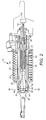
Figure 2 shows, some detail of the ram air turbine ofFigure 1 ; -
Figure 3 shows, schematically, a perspective view of a release mechanism for use with the ram air turbine ofFigures 1 and2 ; -
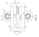
Figure 4 shows a plan view of the release mechanism ofFigure 3 ; -
Figure 5 shows the release mechanism in a locked position; -
Figure 6 shows the release mechanism in an release position; -
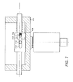
Figure 7 shows the release mechanism in an intermediate position; -
Figure 8 shows the release mechanism in a further intermediate position; and -
Figure 9 shows an alternative embodiment of release mechanism. -
Figure 1 illustrates anRAT system 10 which is secured to anaircraft structure 12 by ahousing 14. Thehousing 14 pivotally supports astrut 16 having aturbine 18 at one end. Theturbine 18 includesblades 20, which impart rotational drive to agenerator 22 andhydraulic pump 30 for example. Anactuator 24 is secured to the strut at afirst end 26 and to the housing at asecond end 28. Theactuator 24 is illustrated in its deployed position. - The
actuator 24 comprises acylinder 32 which is biased by aspring 34 in order to deploy thestrut 16. When thecylinder 32 is retracted, it is held in its retracted position by means of alocking mechanism 36, details of which will be described with reference toFigures 2 to 6 . - With reference to
Figure 2 , thelocking mechanism 36 comprises a locking piston or bolt 38 which is received slidably within asleeve 40. Thelocking piston 38 is biased to the right in the sense ofFigure 2 by means of a biasingspring 42 which extends between aseat 44 provided on thelocking piston 38 and aseat 46 provided on thesleeve 40. - The
extensible cylinder 32 of the actuator is slidably mounted around thesleeve 40. Extension of thecylinder 32 is prevented by lockingelements 48 mounted at the end of the sleeve. In the locking position,respective shoulders cylinder 32 and lockingwedges 48 engage to prevent axial movement of thecylinder 32. - A number of
rollers 54 are mounted in thedistal end 56 of thelocking piston 38. However, it will be noted that when thelocking piston 38 is moved to the right in a direction of arrow 58 under the force of the biasingspring 42, thewedges 48 may displace in the direction ofarrows 60 thereby disengaging theshoulders cylinder 32 to extend to deploy the RAT. This general type of locking mechanism is known in the art and is discussed in some detail, for example inUS 2013/0330121 A1 andUS2013/0327885 A1 . - To unlock the locking mechanism, the
distal end 80 of thelocking piston 38 is attached to arelease mechanism 100 illustrated only schematically inFigure 2 . In essence, as will be described further below, the release mechanism is movable between a locking position in which it retains thelocking piston 38 in the position shown inFigure 2 and a released position in which it permits thelocking piston 38 to move to the right under the force of thespring 42, move therollers 56 of thelocking piston 38 out of alignment with the locking surfaces of the lockingwedges 48, thereby allowing deployment of theactuator cylinder 32. - A release mechanism in accordance with an embodiment of the disclosure will now be described primarily with reference to
Figures 3 to 8 and with occasional reference toFigure 9 . - In broad terms, the
release mechanism 100 comprises ahousing 102 which slidably mounts a lockingbody 104 for reciprocating movement along an axis A. Aforce transmitting element 106 is coupled to the locking body for transmitting a force to the lockingbody 104 for moving the lockingbody 104 from a released position (shown inFigure 4 ) to a locked position (shown inFigure 5 ). A biasingelement 108 acts on the lockingbody 104 in a direction for moving the lockingbody 104 from the released position to the locked position. - The locking
body 104 comprises aslot 110 having afirst slot section 112 extending in a first direction along the axis A and asecond slot section 114 extending transversely from one side of thefirst slot section 112 at an end thereof. - An
actuating element 116 is received in theslot 110, being received in thesecond slot section 114 when the lockingbody 104 is in the locked position and in thefirst slot section 112 when the lockingbody 104 is in the released position. - In more detail, in this embodiment, the locking
body 104 is formed as a rectilinear block which is slidably received in agroove 120 formed in abase wall 122 of thehousing 102 to assist in guiding the lockingbody 104 in a reciprocating movement in thehousing 102. This is of course just an exemplary arrangement and other equivalent means may be provided, for example a rib on thebase wall 122 and a groove provided on the lockingbody 104. - The
force transmission element 106 is suitably coupled to a firstaxial end 124 of the lockingbody 104. In some embodiments, theforce transmission element 106 may be formed integrally with the lockingbody 102. In other embodiments, theforce transmission element 106 may be a separate element suitably attached to the lockingbody 102, for example through a threaded coupling. - The
force transmission element 106 is a generally cylindrical rod, of circular cross section. Other cross sectional shapes may also be used within the scope of the disclosure. Theforce transmission element 106 extends through anopening 126 formed in afirst end wall 128 of thehousing 102. Thefree end 130 of theforce transmission element 106 is suitably attached to an element of the system to be locked or released by themechanism 100. For example, in a ram air turbine application as described above, thefree end 130 of theforce transmission element 106 may be coupled to thelocking piston 38 of the actuator, for example abutting an end of thatlocking piston 38. - The biasing
element 108 is arranged between a secondaxial end 132 of the lockingbody 104 and asecond end wall 134 of thehousing 102, opposite thefirst end wall 128. In this embodiment, the biasing element is a compression spring, in particular a coil spring. However, other types of spring may be used. For example, a tension spring could be provided between thefirst end wall 128 of thehousing 102 and thefirst end 124 of the lockingbody 104. Other biasing arrangements will be readily apparent to the skilled reader. - The
compression spring 108 is mounted around arod 136 which is suitably coupled to the secondaxial end 132 of the lockingbody 102. In some embodiments, therod 136 may be formed integrally with the lockingbody 102. In other embodiments, therod 136 may be a separate element suitably attached to the lockingbody 102, for example through a threaded coupling. - The
rod 136 has a circular cross section in this embodiment. Other cross sectional shapes may also be used within the scope of the disclosure. Therod 136 extends through an opening 138 formed in thesecond end wall 134 of thehousing 102. Therod 136 serves to mount thespring 106, but also assists in the guidance of the lockingbody 104 along the axis A. In this embodiment, therod 136 andforce transmission element 106 are coaxial, but offset configurations also fall within the scope of this disclosure. - The
free end 130 of theforce transmission element 106 is suitably coupled to an element of the system to be locked or unlocked by themechanism 100. For example, in the ram air turbine arrangement discussed above, thefree end 130 may be coupled to thedistal end 80 of thelocking piston 38, for example abutting thedistal end 80 of thelocking piston 38. - As discussed above, the locking
body 104 has aslot 110 formed therein. In this embodiment theslot 110 is a throughslot 110 extending from one side of the lockingbody 104 to the opposed side. Theslot 110 has afirst slot portion 112 which extends in the axial direction, i.e. parallel to the axis of movement A of the lockingbody 104. Theslot 110 also has asecond slot portion 114 which extends transversely from afirst wall 140 of thefirst slot portion 112 at an end of thefirst slot portion 112. - The
second slot portion 114 comprises a firstaxially facing wall 142 extending transversely from thefirst wall 140 of thefirst portion 112 of theslot 110 and an opposed secondaxially facing wall 144. The secondaxially facing wall 144 extends to asecond wall 146 of thefirst slot portion 112. - The
second slot portion 114 has a depth d measured from thefirst wall 140 of thefirst slot portion 112 to itsbase wall 148 and has a length l1 at itsbase wall 148 and a length l2 at thefirst wall 140 of thefirst slot portion 112. Thebase wall 148 is in this embodiment parallel to thefirst wall 140 of thefirst portion 112, but other configurations also fall within the scope of the disclosure. - The first
axially facing wall 142 of thesecond slot portion 114 forms an angle α with thefirst wall 140 of thefirst slot portion 112. The angle α is in this embodiment 90°. In other embodiments, for example as illustrated inFigure 9 , however, the angle α may be a little less than 90°, for example 89°. This forms a corner 150 between the firstaxially facing wall 142 of thesecond slot 114 and thebase wall 148 thereof which has an included angle of less than or equal to 90°. The included angle should not be so acute as to require too large a force to dislodge theactuating element 116 from the corner 150. - The second
axially facing wall 144 of thesecond slot portion 114 forms an angle β with thesecond wall 146 of thefirst slot portion 112. The angle β is greater than 90°, for example greater than 110°, for example 120°. In this embodiment, the second axially facing wall of thesecond slot portion 114 meets thesecond wall 146 of thefirst slot portion 112 at a relativelysharp corner 152, but in other embodiments, thecorner 152 may be chamfered, or, for example as shown inFigure 9 , thewalls curved portion 154. Such an arrangement may be advantageous as it promotes smooth movement of theactuating element 116 along theslot 110. - The
actuating element 116 extends through theslot 110 and projects outwardly throughopposed slots opposed side walls 164, 166 of thehousing 102. Thehousing slots actuating element 116 only in the transverse direction. - The ends 168, 170 of the
actuating element 116 are received inslots 172 formed inplungers 174 oflinear actuators 176, forexample solenoid actuators 176. Theseactuators 176, as will be explained further below, will move theactuating element 116 to effect a release movement of themechanism 100. - The
actuating element 116 has a diameter D which is smaller than the depth of thefirst slot portion 112 so that it may move therealong. Also, the diameter D is, in this embodiment, less than two times the depth d of thesecond slot portion 112. This means that the centre of theactuating element 116 will lie above thefirst wall 140 of thefirst slot portion 112 when theactuating element 116 is received within thesecond slot portion 114. - Returning to the locking
body 104, abore 180 is formed in the secondaxially facing wall 144 for receiving acompression spring 182 and aball 184. Theball 184 may be retained in thebore 182 by suitable means such as a reduceddiameter retaining lip 186 provided at the mouth of thebore 180. Theball 184 is biased outwardly such that it projects into the end of thefirst slot portion 112. The degree of projection is such that when theactuating element 116 is in contact with the firstaxially facing wall 142 of thesecond slot portion 114, it contacts theactuating element 116, as shown, for example inFigure 6 . As will be explained further below, this engagement will assist in retaining theactuating element 116 within thesecond slot portion 114. Theball 184 may, as shown, be biased in a direction towards thesecond slot portion 114 to assist this retention. - Having described the structure of the mechanism, its operation will now be described.
- As discussed above, in use, the
force transmitting element 106 is coupled to a system to be locked or unlocked. In the particular context of a ram air turbine as described, it may be acted on by an end of alocking piston 38. As disclosed, the ram air turbine is locked in a retracted position by thelocking piston 38. When in this position, thelocking piston 38 will be biased by theactuating spring 42, thereby exerting a force F on theforce transmitting element 106. In this condition, therelease mechanism 100 is in the condition shown inFigure 6 . - In this state, the
actuating element 116 is positioned in thesecond slot portion 114, thereby blocked the lockingbody 104 from moving axially, due to the engagement of theactuating element 116 on the firstaxially facing wall 140 of thesecond slot portion 114. The force F will be greater than the force of thespring 108, ensuring engagement of theactuating element 116 with the firstaxially facing wall 140 of thesecond slot portion 114. Theactuating element 116 cannot move axially since it is prevented from doing so by theslots housing 102. The centre of theactuating element 116 lies below the upper edge of the firstaxially facing wall 140, thereby firmly retaining the actuating element in contact with the firstaxially facing wall 140. Theball 184 may also assist in retaining theactuating element 116 in position. - When it is desired to deploy the ram air turbine, the
solenoid actuators 176 are activated, pulling theactuating element 116 downwardly (in the sense of the figures). This moves theactuating element 116 out of thesecond slot portion 114 and into thefirst slot portion 112. As the force F is greater than the biasing force of thespring 108, the lockingbody 104 will move axially under the force F until theactuating element 116 reaches theend 188 of thefirst slot portion 112, as shown inFigure 6 . Theforce transmitting element 106 moves with the lockingbody 104, thereby allowing movement of theactuator locking piston 38, thereby releasing the ram air turbine actuator, to permit deployment of the ram air turbine. - At the same time, the
spring 108 is compressed against thesecond end wall 134 of thehousing 102, again as shown inFigure 6 . Thesolenoid actuators 176 can be deactivated. Theslots 172 in theactuator plungers 174 will allow theactuators 176 to return to their original positions. - When it is required to stow the ram air turbine, a further actuator (not shown) will retract the
locking piston 38 of the ram air turbine actuator. As illustrated inFigure 7 , this will allow thelocking body 104 to move to the left (in the sense of the Figures) under the force of thespring 108. When theactuating element 116 reaches theend wall 144 of thefirst slot portion 112, as illustrated inFigure 8 , it will be moved into thesecond slot portion 114 due to the inclination of theend wall 144 of thefirst slot portion 112. In an alternative embodiment, alternatively or additionally, other means may be used to facilitate this movement, for example a spring element arranged below thesecond slot portion 114. - The
actuating element 116 will be held against the secondaxially facing wall 144 of thesecond slot portion 114 under the biasing force of thespring 108. This position is shown in dotted lines inFigure 5 . Theactuating element 116 will be biased upwardly into thesecond slot portion 114 by theball 184. - When the ram air turbine has been stowed, the
locking piston 38 is once more subjected to the biasing force of theactuator spring 42, which once more biases theforce transmission element 106 in an axial direction. Since, as discussed above, that force is greater than the biasing force of thespring 108, the lockingbody 104 will move slightly axially in the direction of the force F so as to bring the lockingbody 104 back to the locked position shown inFigure 5 , with theactuating element 116 in engagement with the firstaxially facing wall 142 of thesecond slot portion 114. As discussed above, theactuating element 116 will be firmly retained in this position until theactuators 176 are next activated. - It will be seen that during the movement of the locking
body 104 between the two positions described above, theactuating element 116 will disengage from both the first and seconds axially facingwalls second slot portion 114. If the movement were to be slow, then there is a possibility that theactuating element 116 might fall out of thesecond slot portion 114 into thefirst slot portion 112, resulting in premature release of themechanism 100. To avoid this possibly remote eventuality, theball 184 biases theactuating element 116 into thesecond slot portion 114 throughout this movement. Theball 184 may also assist in preventing inadvertent disengagement of theactuating element 116 from thesecond slot portion 114 in use, for example due to vibration. - The embodiment described above may be advantageous in a number of respects. The actuating movement required of the
actuating element 116 can be made relatively small, while at the same time permitting reliable operation of themechanism 100. This may allowsmaller solenoids 176 to be employed. Also, the manufacturing and assembly of the mechanism may be simpler than previous mechanisms. - While the
release mechanism 100 has been described in the context of a ram air turbine, it is not limited to such and themechanism 100 may be used in any installation which requires a release mechanism. - It will also be understood that modifications may be made to the specific embodiment disclosed without departing form the scope of the disclosure. For example, the locking
body 104 need not be rectilinear and could, for example, be cylindrical, with a slot formed therein. The lockingbody 104,force transmission element 106 androd 136 could be formed as a unitary cylindrical body.
Claims (16)
- A release mechanism (100) comprising:a locking body (104) mounted for reciprocating movement in a first axial direction between a locked position and a released position;a force transmitting element (106) coupled to the locking body (104) for transmitting a force (F) to said locking body (104) for moving the locking body (104) from the locked position to the released position;a biasing element (106) acting on the locking body (104) in a direction for moving the locking body (104) from the released position towards the locked position;said locking body (104) comprising a slot (110) comprising a first slot portion (112) extending in said first direction, and a second slot portion (114) extending transversely from one side of said first slot portion (112) at an end thereof; andsaid slot (110) slidably receiving an actuating element (116) therein, said actuating element (116) being movable in a second direction transverse to said first axial direction and received in said second slot portion (114) when the locking body (104) is in the locked position and in said first slot portion (112) when the locking body (104) is in the released position.
- A release mechanism as claimed in claim 1, wherein said second slot portion (114) comprises a first axially facing wall (142) extending transversely from a first wall (140) of said first slot portion (112) and an opposed second axially facing wall (144) extending from an end of the first slot portion (112).
- A release mechanism as claimed in claim 2, wherein said first axially facing wall (142) of said second slot portion (114) forms an angle (α) with said first wall (140) of said first slot portion (112) of less than or equal to 90°.
- A release mechanism as claimed in claim 2 or 3, wherein said second axially facing wall (144) of said second slot portion (114) extends at an angle (β) of greater than 90° relative to a second wall (146) of said first slot portion (112) opposite the first wall (140) of the first slot portion (112).
- A release mechanism as claimed in claim 4 wherein said second axially facing wall (144) of said second slot portion (114) joins said second wall (146 of said first slot portion (112) through a smooth curve (154).
- A release mechanism as claimed in any preceding claim, wherein said actuating element (116) comprises a rod having a circular cross section, the diameter (D) of said rod (116) being less than twice the depth (d) of the second slot portion (114).
- A release mechanism as claimed in any preceding claim, further comprising a spring loaded element, for example a ball (184) mounted for engagement with the actuating element (116) when the actuating element (116) is received in the second slot section (114).
- A release mechanism as claimed in claim 7, wherein the spring loaded element (184) is mounted in an end wall (144) of the first slot portion (112).
- A release mechanism as claimed in any preceding claim, comprising guides (160, 162) for guiding the actuating element (116) in said movement transverse to the first axial direction.
- A release mechanism as claimed in any preceding claim, further comprising a housing (102) slidably mounting the locking body (104).
- A release mechanism as claimed in claim 10 as dependent upon claim 9, wherein said housing (102) comprises a pair of opposed slots (160) receiving opposed ends of said actuating element (116).
- A release mechanism as claimed in claim 10 or 11, wherein said force transmission element extends through a first wall (128) of said housing (104).
- A release mechanism as claimed in claim 10, 11 or 12, wherein said biasing element (118) is a compression spring mounted between a second wall (134) of said housing (102) and said locking body (104).
- A release mechanism as claimed claim 13, comprising a rod (136) attached to said locking body (104) and extending through said second wall (134) of said housing (102), said compression spring (108) being a coil spring mounted around said rod (136).
- A release mechanism as claimed in any preceding claim, comprising at least one actuator (176) attached to said actuating element (116) for moving the actuating element (116) in said second, transverse direction.
- A ram air turbine release mechanism (36) comprising a spring biased locking piston (38) movable between a first position in which the ram air turbine is held in a retracted position and a second position which releases the ram air turbine, said ram air turbine release mechanism further comprising an release mechanism (100) as claimed in any preceding claim, said locking piston (38) being coupled to the force transmission element (106) of the release mechanism (100).
Priority Applications (2)
| Application Number | Priority Date | Filing Date | Title |
|---|---|---|---|
| EP16461546.0A EP3279093B1 (en) | 2016-08-04 | 2016-08-04 | Release mechanism |
| US15/668,781 US10337500B2 (en) | 2016-08-04 | 2017-08-04 | Release mechanism |
Applications Claiming Priority (1)
| Application Number | Priority Date | Filing Date | Title |
|---|---|---|---|
| EP16461546.0A EP3279093B1 (en) | 2016-08-04 | 2016-08-04 | Release mechanism |
Publications (2)
| Publication Number | Publication Date |
|---|---|
| EP3279093A1 true EP3279093A1 (en) | 2018-02-07 |
| EP3279093B1 EP3279093B1 (en) | 2019-03-06 |
Family
ID=56684570
Family Applications (1)
| Application Number | Title | Priority Date | Filing Date |
|---|---|---|---|
| EP16461546.0A Active EP3279093B1 (en) | 2016-08-04 | 2016-08-04 | Release mechanism |
Country Status (2)
| Country | Link |
|---|---|
| US (1) | US10337500B2 (en) |
| EP (1) | EP3279093B1 (en) |
Families Citing this family (1)
| Publication number | Priority date | Publication date | Assignee | Title |
|---|---|---|---|---|
| EP3239052B1 (en) * | 2016-04-30 | 2019-02-06 | Hamilton Sundstrand Corporation | Locking and unlocking mechanism |
Citations (4)
| Publication number | Priority date | Publication date | Assignee | Title |
|---|---|---|---|---|
| US20130078026A1 (en) * | 2011-09-26 | 2013-03-28 | Gary SASSCER | Ejection jack release mechanism |
| US20130327885A1 (en) | 2012-06-06 | 2013-12-12 | Gary SASSCER | Electromechanical actuator lubrication system for ram air turbine |
| US20130327207A1 (en) | 2012-06-06 | 2013-12-12 | Gary SASSCER | Electromechanical actuator damping arrangement for ram air turbine |
| US20130330121A1 (en) | 2012-06-06 | 2013-12-12 | Gary SASSCER | Electromechanical actuator and latch assembly for ram air turbine |
Family Cites Families (6)
| Publication number | Priority date | Publication date | Assignee | Title |
|---|---|---|---|---|
| US2448548A (en) * | 1944-04-05 | 1948-09-07 | George W Purdy | Coupling |
| NO130656C (en) | 1973-01-10 | 1975-01-15 | Kongsberg Vapenfab As | |
| US7296970B2 (en) | 2005-06-08 | 2007-11-20 | Hamilton Sundstrand Corporation | Ram air turbine speed sensing ball detent over-speed prevention mechanism |
| US7980781B2 (en) * | 2009-02-20 | 2011-07-19 | Charles Edward Trice | Self locking mast assembly and method of making |
| US8876474B2 (en) | 2010-11-04 | 2014-11-04 | Hamilton Sundstrand Corporation | Ram air turbine startup |
| US9366315B2 (en) * | 2013-11-13 | 2016-06-14 | Timothy T. Tylaska | Locking quick connect fitting |
-
2016
- 2016-08-04 EP EP16461546.0A patent/EP3279093B1/en active Active
-
2017
- 2017-08-04 US US15/668,781 patent/US10337500B2/en active Active
Patent Citations (4)
| Publication number | Priority date | Publication date | Assignee | Title |
|---|---|---|---|---|
| US20130078026A1 (en) * | 2011-09-26 | 2013-03-28 | Gary SASSCER | Ejection jack release mechanism |
| US20130327885A1 (en) | 2012-06-06 | 2013-12-12 | Gary SASSCER | Electromechanical actuator lubrication system for ram air turbine |
| US20130327207A1 (en) | 2012-06-06 | 2013-12-12 | Gary SASSCER | Electromechanical actuator damping arrangement for ram air turbine |
| US20130330121A1 (en) | 2012-06-06 | 2013-12-12 | Gary SASSCER | Electromechanical actuator and latch assembly for ram air turbine |
Also Published As
| Publication number | Publication date |
|---|---|
| EP3279093B1 (en) | 2019-03-06 |
| US20180038349A1 (en) | 2018-02-08 |
| US10337500B2 (en) | 2019-07-02 |
Similar Documents
| Publication | Publication Date | Title |
|---|---|---|
| US20200023991A1 (en) | Locking and unlocking mechanism | |
| US20130330121A1 (en) | Electromechanical actuator and latch assembly for ram air turbine | |
| US10317929B2 (en) | Locking and unlocking mechanism | |
| US10533647B2 (en) | Locking and unlocking mechanism | |
| US10247285B2 (en) | Locking and unlocking mechanism for ram air turbine | |
| EP3279093B1 (en) | Release mechanism | |
| EP3216701B1 (en) | Latch mechanism | |
| US10370115B2 (en) | Release mechanism | |
| US12191075B2 (en) | Actuator release mechanism | |
| US10310543B2 (en) | Actuator release mechanism | |
| EP3461745B1 (en) | Release mechanism for ram air turbine actuator | |
| US10717544B2 (en) | Release mechanism | |
| US10753440B2 (en) | Actuator release mechanism | |
| EP3741681B1 (en) | Locking and unlocking mechanism | |
| EP3165467B1 (en) | Actuator locking mechanism |
Legal Events
| Date | Code | Title | Description |
|---|---|---|---|
| PUAI | Public reference made under article 153(3) epc to a published international application that has entered the european phase |
Free format text: ORIGINAL CODE: 0009012 |
|
| STAA | Information on the status of an ep patent application or granted ep patent |
Free format text: STATUS: THE APPLICATION HAS BEEN PUBLISHED |
|
| AK | Designated contracting states |
Kind code of ref document: A1 Designated state(s): AL AT BE BG CH CY CZ DE DK EE ES FI FR GB GR HR HU IE IS IT LI LT LU LV MC MK MT NL NO PL PT RO RS SE SI SK SM TR |
|
| AX | Request for extension of the european patent |
Extension state: BA ME |
|
| STAA | Information on the status of an ep patent application or granted ep patent |
Free format text: STATUS: REQUEST FOR EXAMINATION WAS MADE |
|
| GRAP | Despatch of communication of intention to grant a patent |
Free format text: ORIGINAL CODE: EPIDOSNIGR1 |
|
| STAA | Information on the status of an ep patent application or granted ep patent |
Free format text: STATUS: GRANT OF PATENT IS INTENDED |
|
| 17P | Request for examination filed |
Effective date: 20180807 |
|
| RBV | Designated contracting states (corrected) |
Designated state(s): AL AT BE BG CH CY CZ DE DK EE ES FI FR GB GR HR HU IE IS IT LI LT LU LV MC MK MT NL NO PL PT RO RS SE SI SK SM TR |
|
| RIC1 | Information provided on ipc code assigned before grant |
Ipc: B64D 41/00 20060101AFI20180822BHEP Ipc: F15B 15/26 20060101ALI20180822BHEP |
|
| INTG | Intention to grant announced |
Effective date: 20180912 |
|
| GRAS | Grant fee paid |
Free format text: ORIGINAL CODE: EPIDOSNIGR3 |
|
| GRAA | (expected) grant |
Free format text: ORIGINAL CODE: 0009210 |
|
| STAA | Information on the status of an ep patent application or granted ep patent |
Free format text: STATUS: THE PATENT HAS BEEN GRANTED |
|
| AK | Designated contracting states |
Kind code of ref document: B1 Designated state(s): AL AT BE BG CH CY CZ DE DK EE ES FI FR GB GR HR HU IE IS IT LI LT LU LV MC MK MT NL NO PL PT RO RS SE SI SK SM TR |
|
| REG | Reference to a national code |
Ref country code: GB Ref legal event code: FG4D |
|
| REG | Reference to a national code |
Ref country code: CH Ref legal event code: EP Ref country code: AT Ref legal event code: REF Ref document number: 1104200 Country of ref document: AT Kind code of ref document: T Effective date: 20190315 |
|
| REG | Reference to a national code |
Ref country code: DE Ref legal event code: R096 Ref document number: 602016010686 Country of ref document: DE |
|
| REG | Reference to a national code |
Ref country code: IE Ref legal event code: FG4D |
|
| REG | Reference to a national code |
Ref country code: NL Ref legal event code: MP Effective date: 20190306 |
|
| REG | Reference to a national code |
Ref country code: LT Ref legal event code: MG4D |
|
| PG25 | Lapsed in a contracting state [announced via postgrant information from national office to epo] |
Ref country code: NO Free format text: LAPSE BECAUSE OF FAILURE TO SUBMIT A TRANSLATION OF THE DESCRIPTION OR TO PAY THE FEE WITHIN THE PRESCRIBED TIME-LIMIT Effective date: 20190606 Ref country code: FI Free format text: LAPSE BECAUSE OF FAILURE TO SUBMIT A TRANSLATION OF THE DESCRIPTION OR TO PAY THE FEE WITHIN THE PRESCRIBED TIME-LIMIT Effective date: 20190306 Ref country code: LT Free format text: LAPSE BECAUSE OF FAILURE TO SUBMIT A TRANSLATION OF THE DESCRIPTION OR TO PAY THE FEE WITHIN THE PRESCRIBED TIME-LIMIT Effective date: 20190306 Ref country code: ES Free format text: LAPSE BECAUSE OF FAILURE TO SUBMIT A TRANSLATION OF THE DESCRIPTION OR TO PAY THE FEE WITHIN THE PRESCRIBED TIME-LIMIT Effective date: 20190306 Ref country code: SE Free format text: LAPSE BECAUSE OF FAILURE TO SUBMIT A TRANSLATION OF THE DESCRIPTION OR TO PAY THE FEE WITHIN THE PRESCRIBED TIME-LIMIT Effective date: 20190306 |
|
| PG25 | Lapsed in a contracting state [announced via postgrant information from national office to epo] |
Ref country code: LV Free format text: LAPSE BECAUSE OF FAILURE TO SUBMIT A TRANSLATION OF THE DESCRIPTION OR TO PAY THE FEE WITHIN THE PRESCRIBED TIME-LIMIT Effective date: 20190306 Ref country code: NL Free format text: LAPSE BECAUSE OF FAILURE TO SUBMIT A TRANSLATION OF THE DESCRIPTION OR TO PAY THE FEE WITHIN THE PRESCRIBED TIME-LIMIT Effective date: 20190306 Ref country code: HR Free format text: LAPSE BECAUSE OF FAILURE TO SUBMIT A TRANSLATION OF THE DESCRIPTION OR TO PAY THE FEE WITHIN THE PRESCRIBED TIME-LIMIT Effective date: 20190306 Ref country code: GR Free format text: LAPSE BECAUSE OF FAILURE TO SUBMIT A TRANSLATION OF THE DESCRIPTION OR TO PAY THE FEE WITHIN THE PRESCRIBED TIME-LIMIT Effective date: 20190607 Ref country code: BG Free format text: LAPSE BECAUSE OF FAILURE TO SUBMIT A TRANSLATION OF THE DESCRIPTION OR TO PAY THE FEE WITHIN THE PRESCRIBED TIME-LIMIT Effective date: 20190606 Ref country code: RS Free format text: LAPSE BECAUSE OF FAILURE TO SUBMIT A TRANSLATION OF THE DESCRIPTION OR TO PAY THE FEE WITHIN THE PRESCRIBED TIME-LIMIT Effective date: 20190306 |
|
| REG | Reference to a national code |
Ref country code: AT Ref legal event code: MK05 Ref document number: 1104200 Country of ref document: AT Kind code of ref document: T Effective date: 20190306 |
|
| PG25 | Lapsed in a contracting state [announced via postgrant information from national office to epo] |
Ref country code: EE Free format text: LAPSE BECAUSE OF FAILURE TO SUBMIT A TRANSLATION OF THE DESCRIPTION OR TO PAY THE FEE WITHIN THE PRESCRIBED TIME-LIMIT Effective date: 20190306 Ref country code: CZ Free format text: LAPSE BECAUSE OF FAILURE TO SUBMIT A TRANSLATION OF THE DESCRIPTION OR TO PAY THE FEE WITHIN THE PRESCRIBED TIME-LIMIT Effective date: 20190306 Ref country code: RO Free format text: LAPSE BECAUSE OF FAILURE TO SUBMIT A TRANSLATION OF THE DESCRIPTION OR TO PAY THE FEE WITHIN THE PRESCRIBED TIME-LIMIT Effective date: 20190306 Ref country code: SK Free format text: LAPSE BECAUSE OF FAILURE TO SUBMIT A TRANSLATION OF THE DESCRIPTION OR TO PAY THE FEE WITHIN THE PRESCRIBED TIME-LIMIT Effective date: 20190306 Ref country code: IT Free format text: LAPSE BECAUSE OF FAILURE TO SUBMIT A TRANSLATION OF THE DESCRIPTION OR TO PAY THE FEE WITHIN THE PRESCRIBED TIME-LIMIT Effective date: 20190306 Ref country code: PT Free format text: LAPSE BECAUSE OF FAILURE TO SUBMIT A TRANSLATION OF THE DESCRIPTION OR TO PAY THE FEE WITHIN THE PRESCRIBED TIME-LIMIT Effective date: 20190706 Ref country code: AL Free format text: LAPSE BECAUSE OF FAILURE TO SUBMIT A TRANSLATION OF THE DESCRIPTION OR TO PAY THE FEE WITHIN THE PRESCRIBED TIME-LIMIT Effective date: 20190306 |
|
| PG25 | Lapsed in a contracting state [announced via postgrant information from national office to epo] |
Ref country code: PL Free format text: LAPSE BECAUSE OF FAILURE TO SUBMIT A TRANSLATION OF THE DESCRIPTION OR TO PAY THE FEE WITHIN THE PRESCRIBED TIME-LIMIT Effective date: 20190306 Ref country code: SM Free format text: LAPSE BECAUSE OF FAILURE TO SUBMIT A TRANSLATION OF THE DESCRIPTION OR TO PAY THE FEE WITHIN THE PRESCRIBED TIME-LIMIT Effective date: 20190306 |
|
| REG | Reference to a national code |
Ref country code: DE Ref legal event code: R097 Ref document number: 602016010686 Country of ref document: DE |
|
| PG25 | Lapsed in a contracting state [announced via postgrant information from national office to epo] |
Ref country code: AT Free format text: LAPSE BECAUSE OF FAILURE TO SUBMIT A TRANSLATION OF THE DESCRIPTION OR TO PAY THE FEE WITHIN THE PRESCRIBED TIME-LIMIT Effective date: 20190306 Ref country code: IS Free format text: LAPSE BECAUSE OF FAILURE TO SUBMIT A TRANSLATION OF THE DESCRIPTION OR TO PAY THE FEE WITHIN THE PRESCRIBED TIME-LIMIT Effective date: 20190706 |
|
| PLBE | No opposition filed within time limit |
Free format text: ORIGINAL CODE: 0009261 |
|
| STAA | Information on the status of an ep patent application or granted ep patent |
Free format text: STATUS: NO OPPOSITION FILED WITHIN TIME LIMIT |
|
| PG25 | Lapsed in a contracting state [announced via postgrant information from national office to epo] |
Ref country code: DK Free format text: LAPSE BECAUSE OF FAILURE TO SUBMIT A TRANSLATION OF THE DESCRIPTION OR TO PAY THE FEE WITHIN THE PRESCRIBED TIME-LIMIT Effective date: 20190306 |
|
| 26N | No opposition filed |
Effective date: 20191209 |
|
| PG25 | Lapsed in a contracting state [announced via postgrant information from national office to epo] |
Ref country code: SI Free format text: LAPSE BECAUSE OF FAILURE TO SUBMIT A TRANSLATION OF THE DESCRIPTION OR TO PAY THE FEE WITHIN THE PRESCRIBED TIME-LIMIT Effective date: 20190306 |
|
| PG25 | Lapsed in a contracting state [announced via postgrant information from national office to epo] |
Ref country code: TR Free format text: LAPSE BECAUSE OF FAILURE TO SUBMIT A TRANSLATION OF THE DESCRIPTION OR TO PAY THE FEE WITHIN THE PRESCRIBED TIME-LIMIT Effective date: 20190306 |
|
| PG25 | Lapsed in a contracting state [announced via postgrant information from national office to epo] |
Ref country code: MC Free format text: LAPSE BECAUSE OF FAILURE TO SUBMIT A TRANSLATION OF THE DESCRIPTION OR TO PAY THE FEE WITHIN THE PRESCRIBED TIME-LIMIT Effective date: 20190306 Ref country code: LI Free format text: LAPSE BECAUSE OF NON-PAYMENT OF DUE FEES Effective date: 20190831 Ref country code: LU Free format text: LAPSE BECAUSE OF NON-PAYMENT OF DUE FEES Effective date: 20190804 Ref country code: CH Free format text: LAPSE BECAUSE OF NON-PAYMENT OF DUE FEES Effective date: 20190831 |
|
| REG | Reference to a national code |
Ref country code: BE Ref legal event code: MM Effective date: 20190831 |
|
| PG25 | Lapsed in a contracting state [announced via postgrant information from national office to epo] |
Ref country code: IE Free format text: LAPSE BECAUSE OF NON-PAYMENT OF DUE FEES Effective date: 20190804 |
|
| PG25 | Lapsed in a contracting state [announced via postgrant information from national office to epo] |
Ref country code: BE Free format text: LAPSE BECAUSE OF NON-PAYMENT OF DUE FEES Effective date: 20190831 |
|
| PG25 | Lapsed in a contracting state [announced via postgrant information from national office to epo] |
Ref country code: CY Free format text: LAPSE BECAUSE OF FAILURE TO SUBMIT A TRANSLATION OF THE DESCRIPTION OR TO PAY THE FEE WITHIN THE PRESCRIBED TIME-LIMIT Effective date: 20190306 |
|
| PG25 | Lapsed in a contracting state [announced via postgrant information from national office to epo] |
Ref country code: HU Free format text: LAPSE BECAUSE OF FAILURE TO SUBMIT A TRANSLATION OF THE DESCRIPTION OR TO PAY THE FEE WITHIN THE PRESCRIBED TIME-LIMIT; INVALID AB INITIO Effective date: 20160804 Ref country code: MT Free format text: LAPSE BECAUSE OF FAILURE TO SUBMIT A TRANSLATION OF THE DESCRIPTION OR TO PAY THE FEE WITHIN THE PRESCRIBED TIME-LIMIT Effective date: 20190306 |
|
| PG25 | Lapsed in a contracting state [announced via postgrant information from national office to epo] |
Ref country code: MK Free format text: LAPSE BECAUSE OF FAILURE TO SUBMIT A TRANSLATION OF THE DESCRIPTION OR TO PAY THE FEE WITHIN THE PRESCRIBED TIME-LIMIT Effective date: 20190306 |
|
| P01 | Opt-out of the competence of the unified patent court (upc) registered |
Effective date: 20230522 |
|
| PGFP | Annual fee paid to national office [announced via postgrant information from national office to epo] |
Ref country code: DE Payment date: 20250724 Year of fee payment: 10 |
|
| PGFP | Annual fee paid to national office [announced via postgrant information from national office to epo] |
Ref country code: GB Payment date: 20250724 Year of fee payment: 10 |
|
| PGFP | Annual fee paid to national office [announced via postgrant information from national office to epo] |
Ref country code: FR Payment date: 20250725 Year of fee payment: 10 |