EP3278966A1 - Tubular structure and a method of manufacturing thereof - Google Patents
Tubular structure and a method of manufacturing thereof Download PDFInfo
- Publication number
- EP3278966A1 EP3278966A1 EP17182392.5A EP17182392A EP3278966A1 EP 3278966 A1 EP3278966 A1 EP 3278966A1 EP 17182392 A EP17182392 A EP 17182392A EP 3278966 A1 EP3278966 A1 EP 3278966A1
- Authority
- EP
- European Patent Office
- Prior art keywords
- mandrel
- tubular
- tubular member
- composite
- frame
- Prior art date
- Legal status (The legal status is an assumption and is not a legal conclusion. Google has not performed a legal analysis and makes no representation as to the accuracy of the status listed.)
- Granted
Links
Images






Classifications
-
- B—PERFORMING OPERATIONS; TRANSPORTING
- B64—AIRCRAFT; AVIATION; COSMONAUTICS
- B64C—AEROPLANES; HELICOPTERS
- B64C1/00—Fuselages; Constructional features common to fuselages, wings, stabilising surfaces or the like
- B64C1/06—Frames; Stringers; Longerons ; Fuselage sections
- B64C1/08—Geodetic or other open-frame structures
-
- B—PERFORMING OPERATIONS; TRANSPORTING
- B29—WORKING OF PLASTICS; WORKING OF SUBSTANCES IN A PLASTIC STATE IN GENERAL
- B29C—SHAPING OR JOINING OF PLASTICS; SHAPING OF MATERIAL IN A PLASTIC STATE, NOT OTHERWISE PROVIDED FOR; AFTER-TREATMENT OF THE SHAPED PRODUCTS, e.g. REPAIRING
- B29C33/00—Moulds or cores; Details thereof or accessories therefor
- B29C33/44—Moulds or cores; Details thereof or accessories therefor with means for, or specially constructed to facilitate, the removal of articles, e.g. of undercut articles
- B29C33/48—Moulds or cores; Details thereof or accessories therefor with means for, or specially constructed to facilitate, the removal of articles, e.g. of undercut articles with means for collapsing or disassembling
- B29C33/50—Moulds or cores; Details thereof or accessories therefor with means for, or specially constructed to facilitate, the removal of articles, e.g. of undercut articles with means for collapsing or disassembling elastic or flexible
- B29C33/505—Moulds or cores; Details thereof or accessories therefor with means for, or specially constructed to facilitate, the removal of articles, e.g. of undercut articles with means for collapsing or disassembling elastic or flexible cores or mandrels, e.g. inflatable
-
- B—PERFORMING OPERATIONS; TRANSPORTING
- B29—WORKING OF PLASTICS; WORKING OF SUBSTANCES IN A PLASTIC STATE IN GENERAL
- B29C—SHAPING OR JOINING OF PLASTICS; SHAPING OF MATERIAL IN A PLASTIC STATE, NOT OTHERWISE PROVIDED FOR; AFTER-TREATMENT OF THE SHAPED PRODUCTS, e.g. REPAIRING
- B29C43/00—Compression moulding, i.e. applying external pressure to flow the moulding material; Apparatus therefor
- B29C43/02—Compression moulding, i.e. applying external pressure to flow the moulding material; Apparatus therefor of articles of definite length, i.e. discrete articles
- B29C43/04—Compression moulding, i.e. applying external pressure to flow the moulding material; Apparatus therefor of articles of definite length, i.e. discrete articles using movable moulds
- B29C43/06—Compression moulding, i.e. applying external pressure to flow the moulding material; Apparatus therefor of articles of definite length, i.e. discrete articles using movable moulds continuously movable in one direction, e.g. mounted on chains, belts
- B29C43/08—Compression moulding, i.e. applying external pressure to flow the moulding material; Apparatus therefor of articles of definite length, i.e. discrete articles using movable moulds continuously movable in one direction, e.g. mounted on chains, belts with circular movement, e.g. mounted on rolls, turntables
-
- B—PERFORMING OPERATIONS; TRANSPORTING
- B29—WORKING OF PLASTICS; WORKING OF SUBSTANCES IN A PLASTIC STATE IN GENERAL
- B29C—SHAPING OR JOINING OF PLASTICS; SHAPING OF MATERIAL IN A PLASTIC STATE, NOT OTHERWISE PROVIDED FOR; AFTER-TREATMENT OF THE SHAPED PRODUCTS, e.g. REPAIRING
- B29C43/00—Compression moulding, i.e. applying external pressure to flow the moulding material; Apparatus therefor
- B29C43/02—Compression moulding, i.e. applying external pressure to flow the moulding material; Apparatus therefor of articles of definite length, i.e. discrete articles
- B29C43/10—Isostatic pressing, i.e. using non-rigid pressure-exerting members against rigid parts or dies
- B29C43/102—Isostatic pressing, i.e. using non-rigid pressure-exerting members against rigid parts or dies using rigid mould parts specially adapted for moulding articles having an axis of symmetry
-
- B—PERFORMING OPERATIONS; TRANSPORTING
- B29—WORKING OF PLASTICS; WORKING OF SUBSTANCES IN A PLASTIC STATE IN GENERAL
- B29C—SHAPING OR JOINING OF PLASTICS; SHAPING OF MATERIAL IN A PLASTIC STATE, NOT OTHERWISE PROVIDED FOR; AFTER-TREATMENT OF THE SHAPED PRODUCTS, e.g. REPAIRING
- B29C65/00—Joining or sealing of preformed parts, e.g. welding of plastics materials; Apparatus therefor
- B29C65/02—Joining or sealing of preformed parts, e.g. welding of plastics materials; Apparatus therefor by heating, with or without pressure
-
- B—PERFORMING OPERATIONS; TRANSPORTING
- B29—WORKING OF PLASTICS; WORKING OF SUBSTANCES IN A PLASTIC STATE IN GENERAL
- B29C—SHAPING OR JOINING OF PLASTICS; SHAPING OF MATERIAL IN A PLASTIC STATE, NOT OTHERWISE PROVIDED FOR; AFTER-TREATMENT OF THE SHAPED PRODUCTS, e.g. REPAIRING
- B29C65/00—Joining or sealing of preformed parts, e.g. welding of plastics materials; Apparatus therefor
- B29C65/48—Joining or sealing of preformed parts, e.g. welding of plastics materials; Apparatus therefor using adhesives, i.e. using supplementary joining material; solvent bonding
-
- B—PERFORMING OPERATIONS; TRANSPORTING
- B29—WORKING OF PLASTICS; WORKING OF SUBSTANCES IN A PLASTIC STATE IN GENERAL
- B29C—SHAPING OR JOINING OF PLASTICS; SHAPING OF MATERIAL IN A PLASTIC STATE, NOT OTHERWISE PROVIDED FOR; AFTER-TREATMENT OF THE SHAPED PRODUCTS, e.g. REPAIRING
- B29C65/00—Joining or sealing of preformed parts, e.g. welding of plastics materials; Apparatus therefor
- B29C65/56—Joining or sealing of preformed parts, e.g. welding of plastics materials; Apparatus therefor using mechanical means or mechanical connections, e.g. form-fits
-
- B—PERFORMING OPERATIONS; TRANSPORTING
- B29—WORKING OF PLASTICS; WORKING OF SUBSTANCES IN A PLASTIC STATE IN GENERAL
- B29C—SHAPING OR JOINING OF PLASTICS; SHAPING OF MATERIAL IN A PLASTIC STATE, NOT OTHERWISE PROVIDED FOR; AFTER-TREATMENT OF THE SHAPED PRODUCTS, e.g. REPAIRING
- B29C66/00—General aspects of processes or apparatus for joining preformed parts
- B29C66/01—General aspects dealing with the joint area or with the area to be joined
- B29C66/344—Stretching or tensioning the joint area during joining
-
- B—PERFORMING OPERATIONS; TRANSPORTING
- B29—WORKING OF PLASTICS; WORKING OF SUBSTANCES IN A PLASTIC STATE IN GENERAL
- B29C—SHAPING OR JOINING OF PLASTICS; SHAPING OF MATERIAL IN A PLASTIC STATE, NOT OTHERWISE PROVIDED FOR; AFTER-TREATMENT OF THE SHAPED PRODUCTS, e.g. REPAIRING
- B29C67/00—Shaping techniques not covered by groups B29C39/00 - B29C65/00, B29C70/00 or B29C73/00
- B29C67/0014—Shaping techniques not covered by groups B29C39/00 - B29C65/00, B29C70/00 or B29C73/00 for shaping tubes or blown tubular films
- B29C67/0022—Shaping techniques not covered by groups B29C39/00 - B29C65/00, B29C70/00 or B29C73/00 for shaping tubes or blown tubular films using an internal mandrel
-
- B—PERFORMING OPERATIONS; TRANSPORTING
- B29—WORKING OF PLASTICS; WORKING OF SUBSTANCES IN A PLASTIC STATE IN GENERAL
- B29C—SHAPING OR JOINING OF PLASTICS; SHAPING OF MATERIAL IN A PLASTIC STATE, NOT OTHERWISE PROVIDED FOR; AFTER-TREATMENT OF THE SHAPED PRODUCTS, e.g. REPAIRING
- B29C70/00—Shaping composites, i.e. plastics material comprising reinforcements, fillers or preformed parts, e.g. inserts
- B29C70/04—Shaping composites, i.e. plastics material comprising reinforcements, fillers or preformed parts, e.g. inserts comprising reinforcements only, e.g. self-reinforcing plastics
- B29C70/28—Shaping operations therefor
- B29C70/30—Shaping by lay-up, i.e. applying fibres, tape or broadsheet on a mould, former or core; Shaping by spray-up, i.e. spraying of fibres on a mould, former or core
- B29C70/32—Shaping by lay-up, i.e. applying fibres, tape or broadsheet on a mould, former or core; Shaping by spray-up, i.e. spraying of fibres on a mould, former or core on a rotating mould, former or core
- B29C70/323—Shaping by lay-up, i.e. applying fibres, tape or broadsheet on a mould, former or core; Shaping by spray-up, i.e. spraying of fibres on a mould, former or core on a rotating mould, former or core on the inner surface of a rotating mould
-
- B—PERFORMING OPERATIONS; TRANSPORTING
- B29—WORKING OF PLASTICS; WORKING OF SUBSTANCES IN A PLASTIC STATE IN GENERAL
- B29C—SHAPING OR JOINING OF PLASTICS; SHAPING OF MATERIAL IN A PLASTIC STATE, NOT OTHERWISE PROVIDED FOR; AFTER-TREATMENT OF THE SHAPED PRODUCTS, e.g. REPAIRING
- B29C70/00—Shaping composites, i.e. plastics material comprising reinforcements, fillers or preformed parts, e.g. inserts
- B29C70/04—Shaping composites, i.e. plastics material comprising reinforcements, fillers or preformed parts, e.g. inserts comprising reinforcements only, e.g. self-reinforcing plastics
- B29C70/28—Shaping operations therefor
- B29C70/30—Shaping by lay-up, i.e. applying fibres, tape or broadsheet on a mould, former or core; Shaping by spray-up, i.e. spraying of fibres on a mould, former or core
- B29C70/32—Shaping by lay-up, i.e. applying fibres, tape or broadsheet on a mould, former or core; Shaping by spray-up, i.e. spraying of fibres on a mould, former or core on a rotating mould, former or core
- B29C70/323—Shaping by lay-up, i.e. applying fibres, tape or broadsheet on a mould, former or core; Shaping by spray-up, i.e. spraying of fibres on a mould, former or core on a rotating mould, former or core on the inner surface of a rotating mould
- B29C70/326—Shaping by lay-up, i.e. applying fibres, tape or broadsheet on a mould, former or core; Shaping by spray-up, i.e. spraying of fibres on a mould, former or core on a rotating mould, former or core on the inner surface of a rotating mould by rotating the mould around its axis of symmetry
-
- B—PERFORMING OPERATIONS; TRANSPORTING
- B29—WORKING OF PLASTICS; WORKING OF SUBSTANCES IN A PLASTIC STATE IN GENERAL
- B29C—SHAPING OR JOINING OF PLASTICS; SHAPING OF MATERIAL IN A PLASTIC STATE, NOT OTHERWISE PROVIDED FOR; AFTER-TREATMENT OF THE SHAPED PRODUCTS, e.g. REPAIRING
- B29C70/00—Shaping composites, i.e. plastics material comprising reinforcements, fillers or preformed parts, e.g. inserts
- B29C70/04—Shaping composites, i.e. plastics material comprising reinforcements, fillers or preformed parts, e.g. inserts comprising reinforcements only, e.g. self-reinforcing plastics
- B29C70/28—Shaping operations therefor
- B29C70/30—Shaping by lay-up, i.e. applying fibres, tape or broadsheet on a mould, former or core; Shaping by spray-up, i.e. spraying of fibres on a mould, former or core
- B29C70/34—Shaping by lay-up, i.e. applying fibres, tape or broadsheet on a mould, former or core; Shaping by spray-up, i.e. spraying of fibres on a mould, former or core and shaping or impregnating by compression, i.e. combined with compressing after the lay-up operation
- B29C70/342—Shaping by lay-up, i.e. applying fibres, tape or broadsheet on a mould, former or core; Shaping by spray-up, i.e. spraying of fibres on a mould, former or core and shaping or impregnating by compression, i.e. combined with compressing after the lay-up operation using isostatic pressure
-
- B—PERFORMING OPERATIONS; TRANSPORTING
- B29—WORKING OF PLASTICS; WORKING OF SUBSTANCES IN A PLASTIC STATE IN GENERAL
- B29C—SHAPING OR JOINING OF PLASTICS; SHAPING OF MATERIAL IN A PLASTIC STATE, NOT OTHERWISE PROVIDED FOR; AFTER-TREATMENT OF THE SHAPED PRODUCTS, e.g. REPAIRING
- B29C70/00—Shaping composites, i.e. plastics material comprising reinforcements, fillers or preformed parts, e.g. inserts
- B29C70/04—Shaping composites, i.e. plastics material comprising reinforcements, fillers or preformed parts, e.g. inserts comprising reinforcements only, e.g. self-reinforcing plastics
- B29C70/28—Shaping operations therefor
- B29C70/30—Shaping by lay-up, i.e. applying fibres, tape or broadsheet on a mould, former or core; Shaping by spray-up, i.e. spraying of fibres on a mould, former or core
- B29C70/38—Automated lay-up, e.g. using robots, laying filaments according to predetermined patterns
-
- B—PERFORMING OPERATIONS; TRANSPORTING
- B32—LAYERED PRODUCTS
- B32B—LAYERED PRODUCTS, i.e. PRODUCTS BUILT-UP OF STRATA OF FLAT OR NON-FLAT, e.g. CELLULAR OR HONEYCOMB, FORM
- B32B1/00—Layered products having a non-planar shape
- B32B1/08—Tubular products
-
- B—PERFORMING OPERATIONS; TRANSPORTING
- B64—AIRCRAFT; AVIATION; COSMONAUTICS
- B64C—AEROPLANES; HELICOPTERS
- B64C1/00—Fuselages; Constructional features common to fuselages, wings, stabilising surfaces or the like
- B64C1/06—Frames; Stringers; Longerons ; Fuselage sections
- B64C1/061—Frames
-
- B—PERFORMING OPERATIONS; TRANSPORTING
- B64—AIRCRAFT; AVIATION; COSMONAUTICS
- B64C—AEROPLANES; HELICOPTERS
- B64C1/00—Fuselages; Constructional features common to fuselages, wings, stabilising surfaces or the like
- B64C1/06—Frames; Stringers; Longerons ; Fuselage sections
- B64C1/068—Fuselage sections
-
- B—PERFORMING OPERATIONS; TRANSPORTING
- B64—AIRCRAFT; AVIATION; COSMONAUTICS
- B64C—AEROPLANES; HELICOPTERS
- B64C1/00—Fuselages; Constructional features common to fuselages, wings, stabilising surfaces or the like
- B64C1/14—Windows; Doors; Hatch covers or access panels; Surrounding frame structures; Canopies; Windscreens accessories therefor, e.g. pressure sensors, water deflectors, hinges, seals, handles, latches, windscreen wipers
-
- B—PERFORMING OPERATIONS; TRANSPORTING
- B64—AIRCRAFT; AVIATION; COSMONAUTICS
- B64C—AEROPLANES; HELICOPTERS
- B64C1/00—Fuselages; Constructional features common to fuselages, wings, stabilising surfaces or the like
- B64C1/14—Windows; Doors; Hatch covers or access panels; Surrounding frame structures; Canopies; Windscreens accessories therefor, e.g. pressure sensors, water deflectors, hinges, seals, handles, latches, windscreen wipers
- B64C1/1407—Doors; surrounding frames
-
- B—PERFORMING OPERATIONS; TRANSPORTING
- B64—AIRCRAFT; AVIATION; COSMONAUTICS
- B64C—AEROPLANES; HELICOPTERS
- B64C1/00—Fuselages; Constructional features common to fuselages, wings, stabilising surfaces or the like
- B64C1/14—Windows; Doors; Hatch covers or access panels; Surrounding frame structures; Canopies; Windscreens accessories therefor, e.g. pressure sensors, water deflectors, hinges, seals, handles, latches, windscreen wipers
- B64C1/1407—Doors; surrounding frames
- B64C1/1461—Structures of doors or surrounding frames
-
- B—PERFORMING OPERATIONS; TRANSPORTING
- B29—WORKING OF PLASTICS; WORKING OF SUBSTANCES IN A PLASTIC STATE IN GENERAL
- B29C—SHAPING OR JOINING OF PLASTICS; SHAPING OF MATERIAL IN A PLASTIC STATE, NOT OTHERWISE PROVIDED FOR; AFTER-TREATMENT OF THE SHAPED PRODUCTS, e.g. REPAIRING
- B29C43/00—Compression moulding, i.e. applying external pressure to flow the moulding material; Apparatus therefor
- B29C43/02—Compression moulding, i.e. applying external pressure to flow the moulding material; Apparatus therefor of articles of definite length, i.e. discrete articles
- B29C43/027—Compression moulding, i.e. applying external pressure to flow the moulding material; Apparatus therefor of articles of definite length, i.e. discrete articles having an axis of symmetry
- B29C2043/028—Compression moulding, i.e. applying external pressure to flow the moulding material; Apparatus therefor of articles of definite length, i.e. discrete articles having an axis of symmetry using radial compression
-
- B—PERFORMING OPERATIONS; TRANSPORTING
- B29—WORKING OF PLASTICS; WORKING OF SUBSTANCES IN A PLASTIC STATE IN GENERAL
- B29C—SHAPING OR JOINING OF PLASTICS; SHAPING OF MATERIAL IN A PLASTIC STATE, NOT OTHERWISE PROVIDED FOR; AFTER-TREATMENT OF THE SHAPED PRODUCTS, e.g. REPAIRING
- B29C43/00—Compression moulding, i.e. applying external pressure to flow the moulding material; Apparatus therefor
- B29C43/02—Compression moulding, i.e. applying external pressure to flow the moulding material; Apparatus therefor of articles of definite length, i.e. discrete articles
- B29C43/04—Compression moulding, i.e. applying external pressure to flow the moulding material; Apparatus therefor of articles of definite length, i.e. discrete articles using movable moulds
- B29C2043/043—Compression moulding, i.e. applying external pressure to flow the moulding material; Apparatus therefor of articles of definite length, i.e. discrete articles using movable moulds rotating on their own axis without linear displacement
-
- B—PERFORMING OPERATIONS; TRANSPORTING
- B29—WORKING OF PLASTICS; WORKING OF SUBSTANCES IN A PLASTIC STATE IN GENERAL
- B29C—SHAPING OR JOINING OF PLASTICS; SHAPING OF MATERIAL IN A PLASTIC STATE, NOT OTHERWISE PROVIDED FOR; AFTER-TREATMENT OF THE SHAPED PRODUCTS, e.g. REPAIRING
- B29C43/00—Compression moulding, i.e. applying external pressure to flow the moulding material; Apparatus therefor
- B29C43/02—Compression moulding, i.e. applying external pressure to flow the moulding material; Apparatus therefor of articles of definite length, i.e. discrete articles
- B29C43/14—Compression moulding, i.e. applying external pressure to flow the moulding material; Apparatus therefor of articles of definite length, i.e. discrete articles in several steps
- B29C2043/141—Compression moulding, i.e. applying external pressure to flow the moulding material; Apparatus therefor of articles of definite length, i.e. discrete articles in several steps for making single layer articles
- B29C2043/143—Compression moulding, i.e. applying external pressure to flow the moulding material; Apparatus therefor of articles of definite length, i.e. discrete articles in several steps for making single layer articles stepwise in a vertical direction, i.e. each time modifying the thickness
-
- B—PERFORMING OPERATIONS; TRANSPORTING
- B29—WORKING OF PLASTICS; WORKING OF SUBSTANCES IN A PLASTIC STATE IN GENERAL
- B29L—INDEXING SCHEME ASSOCIATED WITH SUBCLASS B29C, RELATING TO PARTICULAR ARTICLES
- B29L2023/00—Tubular articles
-
- B—PERFORMING OPERATIONS; TRANSPORTING
- B29—WORKING OF PLASTICS; WORKING OF SUBSTANCES IN A PLASTIC STATE IN GENERAL
- B29L—INDEXING SCHEME ASSOCIATED WITH SUBCLASS B29C, RELATING TO PARTICULAR ARTICLES
- B29L2031/00—Other particular articles
- B29L2031/30—Vehicles, e.g. ships or aircraft, or body parts thereof
- B29L2031/3076—Aircrafts
- B29L2031/3082—Fuselages
-
- Y—GENERAL TAGGING OF NEW TECHNOLOGICAL DEVELOPMENTS; GENERAL TAGGING OF CROSS-SECTIONAL TECHNOLOGIES SPANNING OVER SEVERAL SECTIONS OF THE IPC; TECHNICAL SUBJECTS COVERED BY FORMER USPC CROSS-REFERENCE ART COLLECTIONS [XRACs] AND DIGESTS
- Y02—TECHNOLOGIES OR APPLICATIONS FOR MITIGATION OR ADAPTATION AGAINST CLIMATE CHANGE
- Y02T—CLIMATE CHANGE MITIGATION TECHNOLOGIES RELATED TO TRANSPORTATION
- Y02T50/00—Aeronautics or air transport
- Y02T50/40—Weight reduction
Definitions
- the present disclosure relates generally to a tubular structure and a method of manufacturing thereof.
- Tubular structures have a wide variety of practical uses. Tubular structures are constructed by various methods and from various materials. Designers of such tubular structures satisfy certain design criteria (such as strength, stiffness, weight and torsional behavior) by varying material types (fibers/resins), orientations of fiber directions and geometric proportions of the tube itself. Another way designers have sought to improve high performance tubes is by developing new manufacturing techniques that can reduce cost and time of manufacturing such tubular structures.
- Existing tubular structure may be fabricated by placing a tubular member horizontally. Prior to insertion of a frame within the tubular member to support it, the tubular member might not possess enough internal strength to support its weight. This can occur when the diameter of the tubular member is large relative to a thickness of the tubular member, e.g., when the tubular member is a fuselage of a commercial jet. Sagging, slumping, or changing the shape of the tubular member may thus occur as a result of the horizontal positioning. To alleviate this problem, additional bracing, jigs, and fixtures may be used to retain the shape of the tubular structure.
- the frame might not be fabricated until the tubular member is completed.
- the frame is fabricated in series with the tubular member. This may increase manufacturing time of the fuselage or any other tubular structure.
- the present disclosure describes examples that relate to a tubular structure and a method of manufacturing thereof.
- the present disclosure describes a method.
- the method comprises: (i) rotating a tubular mandrel about a longitudinal axis of the tubular mandrel, wherein the tubular mandrel is vertically-oriented; (ii) depositing a composite material on an inner surface of the tubular mandrel as the tubular mandrel is rotated so as to form a composite tubular member on the inner surface of the tubular mandrel; (iii) inserting an inner expandable mandrel within the composite tubular member; (iv) expanding the inner expandable mandrel so as to cause the inner expandable mandrel to press the composite tubular member against the inner surface of the tubular mandrel; (v) curing the composite tubular member while being sandwiched between the inner expandable mandrel and the tubular mandrel; (vi) removing the inner expandable mandrel; (vii) placing
- the present disclosure describes a tubular structure.
- the tubular structure comprises: (i) a composite tubular member; and (ii) a geodesic frame disposed within and contacting the composite tubular member, wherein the geodesic frame comprises two oppositely-wound spirals joined at intersection points of the two oppositely-wound spirals.
- the present disclosure describes a tubular structure prepared by a process comprising: (i) rotating a tubular mandrel about a longitudinal axis of the tubular mandrel, wherein the tubular mandrel is vertically-oriented; (ii) depositing a composite material on an inner surface of the tubular mandrel as the tubular mandrel is rotated so as to form a composite tubular member on the inner surface of the tubular mandrel; (iii) inserting an inner expandable mandrel within the composite tubular member; (iv) expanding the inner expandable mandrel so as to cause the inner expandable mandrel to press the composite tubular member against the inner surface of the tubular mandrel; (v) curing the composite tubular member while being sandwiched between the inner expandable mandrel and the tubular mandrel; (vi) removing the inner expandable mandrel; (vii) placing a frame within the composite tubular member; and (viii)
- any enumeration of elements, blocks, or steps in this specification or the claims is for purposes of clarity. Thus, such enumeration should not be interpreted to require or imply that these elements, blocks, or steps adhere to a particular arrangement or are carried out in a particular order.
- a composite tubular structure may include a tubular member and a frame disposed within the tubular member to provide support for the tubular member.
- a fuselage of an aircraft may be made as a composite tubular structure that includes a skin and an internal frame to support the skin.
- a method of fabricating the fuselage skin includes placing the fuselage horizontally. Further, prior to inserting the frame within the skin to support it, the fuselage is incomplete and unsupported and the skin supports its own weight against gravity. However, prior to inserting the frame within the frame, the skin might not possess enough internal strength to support its weight. Sagging, slumping, or changing the shape of the skin may thus occur as a result of the horizontal positioning and the lack of internal structural support for the skin. To alleviate this problem, additional bracing, jigs, and fixtures may be used to retain the shape of the skin.
- the frame of the fuselage is not fabricated until the skin "tube" is completed.
- the frame is fabricated in series with the skin, i.e., after the skin is fabricated. This may increase manufacturing time of the fuselage or any other tubular structure.
- gravity may change a shape of the structure or cause the structure to "slump."
- jigs, clamps, fixtures, shims, etc. may be employed, thus adding cost, complexity, and time to the manufacturing process.
- the structure instead of orienting the tubular structure horizontally, the structure may be orientated vertically such that effect of gravity is reduced.
- FIG. 1 illustrates an apparatus 100 for fabricating a tubular member of a tubular structure in a vertical orientation, in accordance with an example implementation.
- the apparatus 100 includes a vertical cylinder 102 configured to rotate about its own longitudinal axis.
- a motor or engine may be coupled to the vertical cylinder 102 and configured to rotate it about its own longitudinal axis.
- the vertical cylinder 102 surrounds a vertically-oriented tubular mandrel 104.
- the tubular mandrel 104 is coupled to the vertical cylinder 102 and is thus configured to rotate therewith.
- the tubular mandrel 104 may be segmented into arc segments.
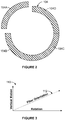
- Figure 2 illustrates a top view of the tubular mandrel 104, in accordance with an example implementation.
- the tubular mandrel 104 may include four arc segments 104A, 104B, 104C, and 104D of a tube. Each of these segments may operate as a forming plate.
- the segments 104A-D are interlocked to prevent formation of seams when a composite material is deposited on an inner surface of the tubular mandrel 104 as described below.
- Figure 2 illustrates four segments. Any other number of segments could be used. For instance, two semi-circular halves could be used instead of the four arc segments 104A-D.
- tubular mandrel 104 could also be segmented vertically based on a length of the tubular member being manufactured. For instance, if the tubular member is a fuselage section of an aircraft, the length of the fuselage section may determine how many vertical segments of the tubular mandrel 104 may be used. As shown in Figure 1 as an example, instead of a single segment 104D, another vertical arc segment 104DD is used. The vertical segments 104D and 104DD are also interlocked. The other segments 104A-C could also have corresponding vertical arc segments.
- a tubular member being manufactured is to be made of a composite material such as carbon fiber reinforced polymer (CFRP).
- CFRP may, for example, include carbon fibered embedded with an epoxy material.
- a CFRP wrapping device e.g., a robotic gantry device
- 106 may be configured to reach into inner space of the tubular mandrel 104 and deposit CFRP material 108 on the inner surface of the tubular mandrel 104.
- the CFRP material 108 may take the form of a tape that is deposited on the inner surface of the tubular mandrel 104.
- the device 106 is configured to move vertically up and down within the inner space of the tubular mandrel 104 while depositing the CFRP material 108 on the inner surface of the tubular mandrel 104. At the same time, the tubular mandrel 104 is rotating along with the vertical cylinder 102. The combination of rotation of the tubular mandrel 104 and vertical motion of the device 106 causes the device 106 to deposit the CFRP material 108 in a diagonal pattern. By varying vertical speed of the device 106 and rotational speed of the tubular mandrel 104, a desired diagonal orientation of the fiber can be achieved.
- Figure 3 illustrates diagonal orientation of deposited composite material, in accordance with an example implementation.
- the x-axis in a graph 110 represents rotation of the tubular mandrel 104, while the y-axis represents vertical motion of the device 106.
- Diagonal line 112 represents diagonal orientation of the CFRP material 108 being deposited. This diagonal orientation is also the diagonal orientation of the fiber embedded within the polymer of the CFRP material 108.
- the carbon fiber embedded in the CFRP material 108 gives strength thereto.
- the CFRP material 108 has higher strength along the direction of the carbon fiber embedded therein.
- the fiber can be laid in the direction in which the strength of the CFRP material 108 is most desired.
- the device 106 may be moved vertically up and down to achieve multiple passes and increase a thickness of the resulting tubular member at given sections. For instance, if the tubular member is a section of a fuselage, it may be desired to increase strength around doors and windows of the aircraft. Thus, multiple passes may be performed by the device 106 for an area around a location of an aircraft door or window.
- the vertical speed of the device 106 may be changed based on which section of the tubular member is being formed. For instance, the device 106 may be slowed down to deposit more CFRP material 108 at a particular area of the tubular member and may be configured to perform multiple passes along that particular area to increase its strength.
- rotational speed of the tubular mandrel 104 may be placed on rotational speed of the tubular mandrel 104 so as to maintain integrity of the CFRP material 108 deposited on the inner surface of the tubular mandrel 104.
- the rotational speed determines a magnitude of a centripetal force that acts to maintain the CFRP material 108 attached to the inner surface of the tubular mandrel 104. If the centripetal force overcomes the effect of gravity of the CFRP material 108, the CFRP material 108 would maintain its integrity and attachment to the tubular mandrel 104.
- the CFRP material 108 In addition to rotational speed of the tubular mandrel 104, other factors that affect the integrity of the CFRP material 108 includes diameter of the tubular member being fabricated (i.e., the diameter of the inner surface of the tubular mandrel 104), weight of the CFRP material 108 (e.g., weight per linear inch), stickiness and adhesiveness of a previously-applied layer of the CFRP material 108. These factors in the aggregate may determine a net force that acts to hold the CFRP material 108 in place while the tubular mandrel 104 is spinning. If this net force is greater than the gravitational force tending to cause the CFRP material 108 to "droop," the CFRP material 108 may maintain its integrity and attachment to the inner surface of the tubular mandrel 104.
- the device 106 may be allowed to "overrun" the ends of the tubular mandrel 104. In this manner, the resulting tubular member made of the CFRP material 108 may have "clean” ends, and “clean” entry and exit fiber placement.
- Figure 4 illustrates an inner mandrel 200, in accordance with an example implementation.
- the inner mandrel 200 may be an expandable mandrel.
- the inner mandrel 200 may include an inflatable bladder. Once the inner mandrel 200 is fully inserted within a tubular member 202 made of the CFRP material 108 shown in Figure 1 , the bladder may be inflated, e.g., by a gas or other fluid. The bladder is inflated until it reaches the inner surface of the tubular member 202 and applies a sufficient pressure to hold the CFRP material 108 of the tubular member 202 against the tubular mandrel 104.
- the inner mandrel 200 may be rotated prior to reaching the inner surface of the tubular member 202. For instance, once fully inserted within the tubular member 202, the inner mandrel 200 may be rotated prior to expansion. Or, in another example, the inner mandrel 200 may be expanded and then prior to reaching the internal walls of the tubular member 202, the inner mandrel 200 may be rotated.
- rotational speed of the inner mandrel 200 may be synchronized with the rotational speed of the tubular mandrel 104 and the tubular member 202 attached thereto.
- the inner mandrel 200 is also rotated to substantially the same rotational speed of the tubular mandrel 104, e.g., within a threshold rotations per minute, RPM, such as 5 RPM.
- RPM rotations per minute
- the tubular member 202 Up to his point of the process, the tubular member 202 has been oriented vertically such that effect of gravity on its shape is reduced and no sagging might occur.
- the next step in the process might be curing the tubular member 202.
- curing may be performed while the tubular member 202 is vertically-oriented.
- orientation of the tubular member 202 may be changed prior to curing. Particularly, now that the tubular member 202 is sandwiched between the tubular mandrel 104 and the inner mandrel 200, integrity of the tubular member 202 is maintained, and its orientation could be changed to a horizontal orientation to facilitate curing.
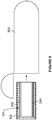
- Figure 5 illustrates curing the tubular member 202, in accordance with an example implementation.
- the assembly including the tubular mandrel 104, the tubular member 202, and the inner mandrel 200 is removed from the vertical cylinder 102 and rotated to a horizontal position by a positioning device.
- the assembly may then be placed into an autoclave 300, as shown in Figure 5 , to be cured at a particular temperature for a predetermined amount of time.
- the vertical cylinder 102 along with the assembly may be inserted into the autoclave 300.
- the assembly including the tubular mandrel 104, the tubular member 202, and the inner mandrel 200 might not be removed from the vertical cylinder 102 prior to rotating the assembly to the horizontal position. Rather, the vertical cylinder 102 and the assembly are rotated to the horizontal position and inserted into the autoclave 300.
- the assembly including the tubular mandrel 104, the tubular member 202, and the inner mandrel 200 is removed from the autoclave 300 and its temperature is allowed to stabilize.
- the inflatable inner mandrel 200 is de-pressurized and removed. After removing the inner mandrel 200, the tubular member 202 could receive a frame therein.
- the frame is fabricated and assembled after the tubular member 202 is fabricated, manufacturing of the tubular structure is inefficient. However, if the frame can be fabricated independent from, and in parallel with, tubular member 202, manufacturing time and cost could be reduced.
- This parallel fabrication can be achieved by a geodesic frame.
- the geodesic frame may be composed of at least two oppositely-wound coils or spirals combined and fastened to make a strong, lightweight inner structure for the tubular member 202.
- the spirals could be made of titanium to achieve the desired strength and light weight.
- Figure 6 illustrates a single spiral 400 of a geodesic frame, in accordance with an example implementation.
- a length "L" of the spiral may be the length of the tubular member 202 and a diameter "D" of the spiral may be the inside diameter of the tubular member 202.
- Another spiral could be oppositely wound and coupled to the spiral 400. For instance, if the spiral 400 is wound in a clockwise direction, another spiral could be wound counter-clockwise and coupled to the spiral 400 to form a cage-like geodesic frame.
- FIG 7 illustrates a geodesic frame 402, in accordance with an example implementation.
- the geodesic frame 402 includes the spiral 400 and another spiral oppositely wound with respect to the spiral 400.
- Figure 8 illustrates a zoomed-in view of the geodesic frame 402, in accordance with an example implementation.
- the geodesic frame 402 includes a second spiral 404 oppositely wound with respect to the spiral 400.
- the geodesic frame 402 may include a greater number of spirals.
- the portion shown in Figure 8 is toward an end of the geodesic frame 402 and includes an end plate 406.
- the end plate 406 facilitates handling the geodesic frame 402 and may remain coupled to the spirals 400 and 404 after insertion into the tubular member 202 or may be removed.
- the two oppositely-wound spirals 400 and 404 cross each other at multiple crossing or intersection points such as intersection point 408.
- the spirals 400 and 404 may be coupled to each other at the intersection points via fasteners or any kind of adhesive bonding.
- a separate coupling fitting could be attached at some or all of the intersection points to fasten the spiral 400 and 404 together.
- one or both spirals 400 and 404 may have notches (e.g., V-shaped notches) that an opposite spiral may pass through. A tight fit may be created at the notches to couple the spirals 400 and 404 to each other.
- fasteners or adhesive could be used at the notch locations to couple the spirals 400 and 404 to each other.
- the spirals 400 and 404 may have a cross section with a "U-shaped,” “C-shaped,” “L-shaped,” “T-shaped,” or “I-shaped” channel.
- the two spirals 400 and 404 may have two opposing "U-shaped” cross sections, and one spiral may fit within the other spiral at the crossing points.
- one spiral may pass underneath the other spiral and a fastener may be used to couple the two spirals as described below with respect to Figure 15 .
- the arrangement of the spiral 400 and 404 of the geodesic frame 402 may create strong crossing joints and good structural rigidity can be attained.
- the pitch and the number of coils of a spiral By varying the pitch and the number of coils of a spiral, the angularity or orientation of these joins can be varied.
- orientation of the spirals 400 and 400 can be determined such that window placement is facilitated.
- Figure 9 illustrates the geodesic frame 402 with aircraft windows, in accordance with an example implementation.
- the pitch and number of coils of the spirals 400 and 404 may be adjusted to create a space for windows such as window 410 of an aircraft.
- Figure 10 illustrates removal of the inner mandrel 200, in accordance with an example implementation.
- the assembly including the tubular mandrel 104, the tubular member 202, and the inner mandrel 200 is removed from the autoclave 300 and its temperature is allowed to stabilize.
- the inflatable inner mandrel 200 is de-pressurized and removed.
- the inner mandrel 200 can, for example, be pulled from the inner space of the tubular member 202 by way of a robotic arm or manipulator.
- the tubular mandrel 104 may be retained so as to maintain a circular or cylindrical shape of the tubular member 202.
- the geodesic frame 402 may have been fabricated or assembled independently in parallel with fabrication of the tubular member 202.
- Figure 11 illustrates the geodesic frame 402 prior to insertion into the tubular member 202
- 5C illustrates insertion of the geodesic frame 402 into the tubular member 202, in accordance with an example implementation.
- the geodesic frame 402 may have a diameter "d 1 " and the tubular member 202 may have an inside diameter "d 2 .” These diameters may be substantially the same or the diameter "d 1 " may be slightly larger than the diameter "d 2 .” In order to facilitate insertion of the geodesic frame 402 into the tubular member 202, the diameter "d 1 " may be slightly decreased temporarily until the geodesic frame 402 is inserted.
- the geodesic frame 402 may be coupled to horizontal assembly mandrel 500, which could be a manipulator or an arm of a robotic device 502, for example.
- the robotic device 502 may be configured to slightly, axially stretch the geodesic frame 402 via the mandrel 500 so as to decrease the outside diameter "d 1 " to a diameter "d 3 ,” which is smaller than both "d 1 " and "d 2 .”
- the mandrel 500 may then place the geodesic frame 402 into the tubular member 202.
- Figure 13 illustrates the geodesic frame 402 contacting the tubular member 202, in accordance with an example implementation.
- the mandrel 500 may be slowly retracted, allowing the geodesic frame 402 to expand back to its unstretched diameter "d 1 .”
- the geodesic frame 402 contacts the inner surface of the tubular member 202, and thus supports the tubular member 202.
- the expansion of the geodesic frame 402 could also be accomplished by compressing it by the mandrel 500 to increase the outer diameter of the geodesic frame 402 and bring the geodesic frame 402 into contact with an inner surface of the tubular member 202.
- the geodesic frame 402 may be pre-fastened to the tubular member 202 prior to extraction of the tubular member 202 and the geodesic frame 402 from the tubular mandrel 104.
- fasteners could be drilled from the inside out to pre-fasten the geodesic frame 402 to the tubular member 202.
- the tubular mandrel 104 may include replaceable inserts at the locations where the fasteners are drilled to prevent the fasteners from breaking out through the tubular mandrel 104. These fasteners could later be replaced by countersunk "outside-in" fasteners.
- tubular member 202 and the geodesic frame 402 represent a fuselage
- windows and doors of the aircraft could be cut out and fitted at this stage of the manufacturing process. Edges of the tubular member 202 could then be trimmed and finished.
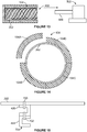
- FIG. 14 illustrates extraction of a tubular structure, in accordance with an example implementation.
- Figure 14 shows the tubular member 202 disposed within the tubular mandrel 104.
- the geodesic frame 402 is not shown to reduce visual clutter in the drawing.
- the tubular mandrel 104 may include several interlocked arc segments such as the segments 104A-D. These segments could be disassembled from around the tubular member 202 as illustrated by removing the segments 104A in Figure 14 .
- the tubular member 202 and the geodesic frame 402 disposed therein could then be extracted.
- Permanent fasteners can be installed to couple the spirals 400 and 404 of the geodesic frame 402 to each other and couple the geodesic frame 402 to the tubular member 202.
- Figure 15 illustrates fastening the spirals 400 and 404 of the geodesic frame 402 to each other and fastening the geodesic frame 402 to the tubular member 202, in accordance with an example implementation.
- a fastener 700 could be used to join an outside spiral, i.e., the spiral 400 in Figure 15 , of the geodesic frame 402 to the tubular member 202, which is made of composite material.
- the spirals 400 and 404 could be made of titanium (Ti).
- the fastener 702 is a Ti-Ti joint fastener.
- the spirals 400 and 404 are illustrated having "C,” or "U" channel-shaped cross sections. Other cross sections could be used and the example shown is for illustration only.
- spirals 400 and 404 overlap each other in Figure 15 .
- the two opposing "C" or "U” channel-shaped cross sections may fit with each other instead of overlapping. Additional reinforcements could be added at the cross joints between the spirals 400 and 404 to increase integrity of the geodesic frame 402 and the resulting composite tubular structure that includes the tubular member 202 and the geodesic frame 402.
- a secondary structure could be coupled to the geodesic frame 402.
- the secondary structure could, for example, contact a free inside surface 704 of the spiral 404.
- the process described above allows for fabricating the geodesic frame 402 in parallel with the fabricating the tubular member 202 to reduce overall manufacturing time. Additionally, the process allows for the tubular member 202 to be vertically-oriented until it gains its structural integrity to reduce the use of bracing, jigs, and fixtures. Additionally, rather than using a complex series of frames and stringers to support the tubular member 202, the geodesic frame 402 described above reduces the number of parts and cost of the frame supporting the tubular member 202.
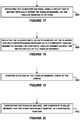
- FIG 16 is a flowchart of a method 800 for manufacturing a tubular structure, in accordance with an example implementation.
- the method 800 represents a process that may be used, for example, to make or prepare the tubular structure including the tubular member 202 and the geodesic frame 402 as described above with respect to Figures 1-15 .
- the method 800 may include one or more operations or actions as illustrated by one or more of blocks 802-818. Although the blocks are illustrated in a sequential order, these blocks may in some instances be performed in parallel, and/or in a different order than those described herein. Also, the various blocks may be combined into fewer blocks, divided into additional blocks, and/or removed based upon the desired implementation.
- the method 800 includes rotating a tubular mandrel about a longitudinal axis of the tubular mandrel, where the tubular mandrel is vertically-oriented.
- a vertical cylinder e.g., the vertical cylinder 102
- the vertical cylinder may surround a vertically-oriented tubular mandrel (e.g., the tubular mandrel 104).
- the tubular mandrel may include a plurality of interlocked arc segments of a tube (e.g., the segments 104A-D and 104DD).
- the tubular mandrel is coupled to the vertical cylinder and is thus configured to rotate therewith.
- the method 800 includes depositing a composite material on an inner surface of the tubular mandrel as the tubular mandrel is rotated so as to form a composite tubular member on the inner surface of the tubular mandrel.
- a CFRP wrapping device e.g., a robotic gantry device such as the device 106 may be configured to reach into the inner space formed within the tubular mandrel and deposit CFRP material (e.g., the CFRP material 108) on an inner surface of the tubular mandrel.
- Figure 17 is a flowchart of a method for use with the method 800, in accordance with an example implementation.
- the method includes depositing the composite material using a CFRP wrapping device that is moving vertically within the tubular mandrel as the tubular mandrel is rotated.
- the combination of rotation of the tubular mandrel and vertical motion of the CFRP wrapping device causes the CFRP wrapping device to deposit the CFRP material in a diagonal pattern.
- a desired diagonal orientation of the fiber can be achieved.
- the method 800 includes inserting an inner expandable mandrel within the composite tubular member.
- an inner mandrel e.g., the inner mandrel 200
- the inner mandrel may include an inflatable outer bladder.
- the inner expandable mandrel may be inserted within the tubular member in a deflated state to facilitate the insertion.
- the method 800 includes expanding the inner expandable mandrel so as to cause the inner expandable mandrel to press the composite tubular member against the inner surface of the tubular mandrel. Once the inner mandrel is fully inserted within a tubular member made of the CFRP material, the method 800 includes expanding the inner expandable mandrel.
- Figure 18 is a flowchart of a method for use with the method 800, in accordance with an example implementation.
- the method includes inflating the bladder until an outer surface of the bladder reaches the inner surface of the tubular member and applies a sufficient predetermined pressure (e.g., 100 pounds per square inch (psi), or within a range of about 50-250 psi in other examples) to hold or secure the CFRP material of the tubular member against the inner surface of the tubular mandrel.
- a sufficient predetermined pressure e.g., 100 pounds per square inch (psi), or within a range of about 50-250 psi in other examples
- the inner mandrel may be rotated prior to reaching the inner surface of the tubular member. For instance, once fully inserted within the tubular member, the inner mandrel may be rotated prior to expansion. Or, in another example, the inner mandrel may be expanded and then prior to reaching the internal walls of the tubular member, the inner mandrel may be rotated.
- rotational speed of the inner mandrel may be synchronized with the rotational speed of the tubular mandrel and the tubular member attached thereto. In other words, if the tubular mandrel is rotating at a particular rotational speed, the inner mandrel is also rotated to substantially the same rotational speed of the tubular mandrel.
- Figure 19 is a flowchart of an example method for use with the method 800, in accordance with an example implementation.
- the method 800 includes curing the composite tubular member while being sandwiched between the inner expandable mandrel and the tubular mandrel.
- the assembly including the tubular mandrel, the tubular member, and the inner mandrel is removed from the vertical cylinder.
- Figure 20 is a flowchart of an example method for use with the method 800, in accordance with an example implementation.
- the method includes orientating the tubular mandrel, the tubular member, and the inner expandable mandrel in a horizontal position, prior to the curing, by a positioning device as described with respect to Figure 5 .
- the assembly may then be placed into an autoclave to be cured at a particular temperature for a predetermined amount of time (e.g., an hour).
- a predetermined amount of time e.g., an hour
- the vertical cylinder along with the assembly is inserted into the autoclave.
- the method 800 includes removing the inner expandable mandrel.
- the assembly including the tubular mandrel, the tubular member, and the inner mandrel is removed from the autoclave and its temperature is allowed to stabilize.
- the inflatable inner mandrel may de-pressurized or deflated and removed.
- the tubular member could receive a frame therein.
- the method 800 includes placing a frame within the composite tubular member.
- the frame can be fabricated independent from and in parallel with tubular member so as to reduce manufacturing time and cost. Any type of supporting frame could be used.
- the frame could be a geodesic frame such as the geodesic frame 402 described above.
- the geodesic frame may be composed of at least two oppositely-wound spirals combined and joined at intersection points of the two oppositely-wound spirals to make a strong, lightweight inner supporting structure for the tubular member.
- Figure 21 is a flowchart of an example method for use with the method 800, in accordance with an example implementation.
- the method includes axially stretching the geodesic frame to reduce a diameter of the geodesic frame.
- the method 800 then includes inserting the axially stretched geodesic frame within the composite tubular member.
- the method further includes releasing the geodesic frame to cause the diameter of the geodesic frame to expand, thereby causing the geodesic frame to contact and support the composite tubular member.
- the method 800 includes removing the tubular mandrel so as to obtain the composite tubular member with the frame placed therein.
- the tubular member and the frame disposed therein could be extracted from the tubular mandrel by, for example, disassembling arc segments of the tubular mandrel as described with respect to Figure 14 .
- the tubular member and the frame disposed therein could then be extracted. In this manner, a composite tubular structure that includes the tubular member and the frame disposed therein is obtained.
- a method comprising:
- the tubular mandrel is rotated at a particular rotational speed, and wherein the inner expandable mandrel is rotated at the particular rotational speed such that respective rotations of the inner expandable mandrel and the tubular mandrel are synchronized.
- the method further comprises:
- the inner expandable mandrel includes an inflatable bladder, and wherein expanding the inner expandable mandrel comprises:
- the method further comprises:
- the tubular mandrel comprises a plurality of interlocked arc segments of a tube.
- depositing the composite material on the inner surface of the tubular mandrel comprises:
- the frame is a geodesic frame comprising two oppositely-wound spirals joined at intersection points of the two oppositely-wound spirals.
- placing the geodesic frame within the composite tubular member comprises:
- At least one of the two oppositely-wound spirals of the geodesic frame has a U-shaped or an L-shaped cross section.
- the geodesic frame is coupled to the composite tubular member using a plurality of fasteners or adhesive bonding.
- At least one of the two oppositely-wound spirals of the geodesic frame has a U-shaped, L-shaped, T-shaped, or I-shaped cross section.
- the two oppositely-wound spirals are joined at the intersection points using a plurality of fasteners or adhesive bonding.
- At least one of the two oppositely-wound spirals of the geodesic frame has a plurality of notches at the intersection points to facilitate joining the two oppositely-wound spirals.
- the tubular structure comprises at least a section of a fuselage.
- a tubular structure prepared by a process comprising:
- the frame is a geodesic frame comprising two oppositely-wound spirals joined at intersection points of the two oppositely-wound spirals, and wherein the process further comprises:
- the process further comprises:
- depositing the composite material on the inner surface of the tubular mandrel comprises:
Landscapes
- Engineering & Computer Science (AREA)
- Mechanical Engineering (AREA)
- Aviation & Aerospace Engineering (AREA)
- Chemical & Material Sciences (AREA)
- Composite Materials (AREA)
- Robotics (AREA)
- Moulding By Coating Moulds (AREA)
Abstract
Description
- The present disclosure relates generally to a tubular structure and a method of manufacturing thereof.
- Tubular structures have a wide variety of practical uses. Tubular structures are constructed by various methods and from various materials. Designers of such tubular structures satisfy certain design criteria (such as strength, stiffness, weight and torsional behavior) by varying material types (fibers/resins), orientations of fiber directions and geometric proportions of the tube itself. Another way designers have sought to improve high performance tubes is by developing new manufacturing techniques that can reduce cost and time of manufacturing such tubular structures.
- Existing tubular structure may be fabricated by placing a tubular member horizontally. Prior to insertion of a frame within the tubular member to support it, the tubular member might not possess enough internal strength to support its weight. This can occur when the diameter of the tubular member is large relative to a thickness of the tubular member, e.g., when the tubular member is a fuselage of a commercial jet. Sagging, slumping, or changing the shape of the tubular member may thus occur as a result of the horizontal positioning. To alleviate this problem, additional bracing, jigs, and fixtures may be used to retain the shape of the tubular structure.
- Further, the frame might not be fabricated until the tubular member is completed. In other words, the frame is fabricated in series with the tubular member. This may increase manufacturing time of the fuselage or any other tubular structure.
- Therefore methods, processes, and structures are desired that allow for the frame to be fabricated in parallel with the tubular member to reduce overall manufacturing time and allow the tubular member to gain its structural integrity early in the fabrication process to reduce the use of bracing, jigs, and fixtures.
- The present disclosure describes examples that relate to a tubular structure and a method of manufacturing thereof. In one aspect, the present disclosure describes a method. The method comprises: (i) rotating a tubular mandrel about a longitudinal axis of the tubular mandrel, wherein the tubular mandrel is vertically-oriented; (ii) depositing a composite material on an inner surface of the tubular mandrel as the tubular mandrel is rotated so as to form a composite tubular member on the inner surface of the tubular mandrel; (iii) inserting an inner expandable mandrel within the composite tubular member; (iv) expanding the inner expandable mandrel so as to cause the inner expandable mandrel to press the composite tubular member against the inner surface of the tubular mandrel; (v) curing the composite tubular member while being sandwiched between the inner expandable mandrel and the tubular mandrel; (vi) removing the inner expandable mandrel; (vii) placing a frame within the composite tubular member; and (viii) removing the tubular mandrel so as to obtain the composite tubular member with the frame placed therein.
- In another aspect, the present disclosure describes a tubular structure. The tubular structure comprises: (i) a composite tubular member; and (ii) a geodesic frame disposed within and contacting the composite tubular member, wherein the geodesic frame comprises two oppositely-wound spirals joined at intersection points of the two oppositely-wound spirals.
- In still another aspect, the present disclosure describes a tubular structure prepared by a process comprising: (i) rotating a tubular mandrel about a longitudinal axis of the tubular mandrel, wherein the tubular mandrel is vertically-oriented; (ii) depositing a composite material on an inner surface of the tubular mandrel as the tubular mandrel is rotated so as to form a composite tubular member on the inner surface of the tubular mandrel; (iii) inserting an inner expandable mandrel within the composite tubular member; (iv) expanding the inner expandable mandrel so as to cause the inner expandable mandrel to press the composite tubular member against the inner surface of the tubular mandrel; (v) curing the composite tubular member while being sandwiched between the inner expandable mandrel and the tubular mandrel; (vi) removing the inner expandable mandrel; (vii) placing a frame within the composite tubular member; and (viii) removing the tubular mandrel so as to obtain the composite tubular member with the frame placed therein.
- The foregoing summary is illustrative only and is not intended to be in any way limiting. In addition to the illustrative aspects, examples, and features described above, further aspects, examples, and features will become apparent by reference to the figures and the following detailed description.
- The novel features believed characteristic of the illustrative examples are set forth in the appended claims. The illustrative examples, however, as well as a preferred mode of use, further objectives and descriptions thereof, will best be understood by reference to the following detailed description of an illustrative example of the present disclosure when read in conjunction with the accompanying Figures.
-
Figure 1 illustrates an apparatus for fabricating a tubular member of a tubular structure in a vertical orientation, in accordance with an example implementation. -
Figure 2 illustrates a top view of a tubular mandrel, in accordance with an example implementation. -
Figure 3 illustrates diagonal orientation of deposited composite material, in accordance with an example implementation. -
Figure 4 illustrates an inner mandrel, in accordance with an example implementation. -
Figure 5 illustrates curing a tubular member, in accordance with an example implementation. -
Figure 6 illustrates a single spiral of a geodesic frame, in accordance with an example implementation. -
Figure 7 illustrates a geodesic frame, in accordance with an example implementation. -
Figure 8 illustrates a zoomed-in view of the geodesic frame shown inFigure 7 , in accordance with an example implementation. -
Figure 9 illustrates a geodesic frame with aircraft windows, in accordance with an example implementation. -
Figure 10 illustrates removal of an inner mandrel, in accordance with an example implementation. -
Figure 11 illustrates a geodesic frame prior to insertion into a tubular member, in accordance with an example implementation. -
Figure 12 illustrates insertion of a geodesic frame into a tubular member, in accordance with an example implementation. -
Figure 13 illustrates a geodesic frame contacting a tubular member, in accordance with an example implementation. -
Figure 14 extraction of a tubular structure, in accordance with an example implementation. -
Figure 15 illustrates fastening spirals of a geodesic frame to each other and fastening the geodesic frame to a tubular member, in accordance with an example implementation. -
Figure 16 is a flowchart of a method for manufacturing a tubular structure, in accordance with an example implementation. -
Figure 17 is a flowchart of an example method for use with the method ofFigure 16 , in accordance with an example implementation. -
Figure 18 is a flowchart of an example method for use with the method ofFigure 16 , in accordance with an example implementation. -
Figure 19 is a flowchart of an example method for use with the method ofFigure 16 , in accordance with an example implementation. -
Figure 20 is a flowchart of an example method for use with the method ofFigure 16 , in accordance with an example implementation. -
Figure 21 is a flowchart of an example method for use with the method ofFigure 16 , in accordance with an example implementation. - The following detailed description describes various features and functions of the disclosed systems and methods with reference to the accompanying figures. The illustrative system and method examples described herein are not meant to be limiting. It may be readily understood that certain aspects of the disclosed systems and methods can be arranged and combined in a wide variety of different configurations, all of which are contemplated herein.
- Further, unless context suggests otherwise, the features illustrated in each of the figures may be used in combination with one another. Thus, the figures should be generally viewed as component aspects of one or more overall implementations, with the understanding that not all illustrated features are necessary for each implementation.
- Additionally, any enumeration of elements, blocks, or steps in this specification or the claims is for purposes of clarity. Thus, such enumeration should not be interpreted to require or imply that these elements, blocks, or steps adhere to a particular arrangement or are carried out in a particular order.
- By the term "substantially" it is meant that the recited characteristic, parameter, or value need not be achieved exactly, but that deviations or variations, including for example, tolerances, measurement error, measurement accuracy limitations and other factors known to skill in the art, may occur in amounts that do not preclude the effect the characteristic was intended to provide.
- In examples, a composite tubular structure may include a tubular member and a frame disposed within the tubular member to provide support for the tubular member. For instance, a fuselage of an aircraft may be made as a composite tubular structure that includes a skin and an internal frame to support the skin.
- In an example, a method of fabricating the fuselage skin includes placing the fuselage horizontally. Further, prior to inserting the frame within the skin to support it, the fuselage is incomplete and unsupported and the skin supports its own weight against gravity. However, prior to inserting the frame within the frame, the skin might not possess enough internal strength to support its weight. Sagging, slumping, or changing the shape of the skin may thus occur as a result of the horizontal positioning and the lack of internal structural support for the skin. To alleviate this problem, additional bracing, jigs, and fixtures may be used to retain the shape of the skin.
- Further, in this example, the frame of the fuselage is not fabricated until the skin "tube" is completed. In other words, the frame is fabricated in series with the skin, i.e., after the skin is fabricated. This may increase manufacturing time of the fuselage or any other tubular structure.
- Disclosed herein are methods, processes, and structures that allows for the frame to be fabricated in parallel with the skin to reduce overall manufacturing time. Additionally, the disclosed methods and processes allow for the tubular member, e.g., the skin of the fuselage, to gain its structural integrity early in the fabrication process to reduce the use of bracing, jigs, and fixtures. Additionally, rather than using a complex series of frames and stringers to support the tubular member, disclosed herein is a geodesic frame that includes two oppositely-wound spirals that reduce the number of parts and cost of the frame.
- As mentioned above, in fabricating tubular or barrel-shaped structures, gravity may change a shape of the structure or cause the structure to "slump." To preclude this slumping from happening, jigs, clamps, fixtures, shims, etc. may be employed, thus adding cost, complexity, and time to the manufacturing process. Alternatively, instead of orienting the tubular structure horizontally, the structure may be orientated vertically such that effect of gravity is reduced.
-
Figure 1 illustrates anapparatus 100 for fabricating a tubular member of a tubular structure in a vertical orientation, in accordance with an example implementation. Theapparatus 100 includes avertical cylinder 102 configured to rotate about its own longitudinal axis. For instance a motor or engine may be coupled to thevertical cylinder 102 and configured to rotate it about its own longitudinal axis. Thevertical cylinder 102 surrounds a vertically-orientedtubular mandrel 104. Thetubular mandrel 104 is coupled to thevertical cylinder 102 and is thus configured to rotate therewith. - The
tubular mandrel 104 may be segmented into arc segments.Figure 2 illustrates a top view of thetubular mandrel 104, in accordance with an example implementation. As shown, thetubular mandrel 104 may include fourarc segments segments 104A-D are interlocked to prevent formation of seams when a composite material is deposited on an inner surface of thetubular mandrel 104 as described below. AlthoughFigure 2 illustrates four segments. Any other number of segments could be used. For instance, two semi-circular halves could be used instead of the fourarc segments 104A-D. - Further, the
tubular mandrel 104 could also be segmented vertically based on a length of the tubular member being manufactured. For instance, if the tubular member is a fuselage section of an aircraft, the length of the fuselage section may determine how many vertical segments of thetubular mandrel 104 may be used. As shown inFigure 1 as an example, instead of asingle segment 104D, another vertical arc segment 104DD is used. Thevertical segments 104D and 104DD are also interlocked. Theother segments 104A-C could also have corresponding vertical arc segments. - In some exampled described herein, a tubular member being manufactured is to be made of a composite material such as carbon fiber reinforced polymer (CFRP). The CFRP may, for example, include carbon fibered embedded with an epoxy material. However, other example materials could be used as well. Referring back to
Figure 1 , a CFRP wrapping device (e.g., a robotic gantry device) 106 may be configured to reach into inner space of thetubular mandrel 104 anddeposit CFRP material 108 on the inner surface of thetubular mandrel 104. In an example, theCFRP material 108 may take the form of a tape that is deposited on the inner surface of thetubular mandrel 104. - The
device 106 is configured to move vertically up and down within the inner space of thetubular mandrel 104 while depositing theCFRP material 108 on the inner surface of thetubular mandrel 104. At the same time, thetubular mandrel 104 is rotating along with thevertical cylinder 102. The combination of rotation of thetubular mandrel 104 and vertical motion of thedevice 106 causes thedevice 106 to deposit theCFRP material 108 in a diagonal pattern. By varying vertical speed of thedevice 106 and rotational speed of thetubular mandrel 104, a desired diagonal orientation of the fiber can be achieved. -
Figure 3 illustrates diagonal orientation of deposited composite material, in accordance with an example implementation. As illustrated, the x-axis in agraph 110 represents rotation of thetubular mandrel 104, while the y-axis represents vertical motion of thedevice 106.Diagonal line 112 represents diagonal orientation of theCFRP material 108 being deposited. This diagonal orientation is also the diagonal orientation of the fiber embedded within the polymer of theCFRP material 108. - The carbon fiber embedded in the
CFRP material 108 gives strength thereto. Particularly, theCFRP material 108 has higher strength along the direction of the carbon fiber embedded therein. Thus, by controlling diagonal orientation of the fiber by controlling the vertical motion of thedevice 106 and the rotational speed of thetubular mandrel 104, the fiber can be laid in the direction in which the strength of theCFRP material 108 is most desired. - Further, the
device 106 may be moved vertically up and down to achieve multiple passes and increase a thickness of the resulting tubular member at given sections. For instance, if the tubular member is a section of a fuselage, it may be desired to increase strength around doors and windows of the aircraft. Thus, multiple passes may be performed by thedevice 106 for an area around a location of an aircraft door or window. - Further, the vertical speed of the
device 106 may be changed based on which section of the tubular member is being formed. For instance, thedevice 106 may be slowed down to depositmore CFRP material 108 at a particular area of the tubular member and may be configured to perform multiple passes along that particular area to increase its strength. - In examples, other constraints may be placed on rotational speed of the
tubular mandrel 104 so as to maintain integrity of theCFRP material 108 deposited on the inner surface of thetubular mandrel 104. The rotational speed determines a magnitude of a centripetal force that acts to maintain theCFRP material 108 attached to the inner surface of thetubular mandrel 104. If the centripetal force overcomes the effect of gravity of theCFRP material 108, theCFRP material 108 would maintain its integrity and attachment to thetubular mandrel 104. - In addition to rotational speed of the
tubular mandrel 104, other factors that affect the integrity of theCFRP material 108 includes diameter of the tubular member being fabricated (i.e., the diameter of the inner surface of the tubular mandrel 104), weight of the CFRP material 108 (e.g., weight per linear inch), stickiness and adhesiveness of a previously-applied layer of theCFRP material 108. These factors in the aggregate may determine a net force that acts to hold theCFRP material 108 in place while thetubular mandrel 104 is spinning. If this net force is greater than the gravitational force tending to cause theCFRP material 108 to "droop," theCFRP material 108 may maintain its integrity and attachment to the inner surface of thetubular mandrel 104. - In an example, the
device 106 may be allowed to "overrun" the ends of thetubular mandrel 104. In this manner, the resulting tubular member made of theCFRP material 108 may have "clean" ends, and "clean" entry and exit fiber placement. - During deposition of the
CFRP material 108, rotation of thetubular mandrel 104 continues to maintain pressure on theCFRP material 108 against the inner surface of thetubular mandrel 104 due to the centripetal force resulting from the rotation. Otherwise, if the rotation is stopped, theCFRP material 108 may droop and lose its attachment to thetubular mandrel 104, because theCFRP material 108 is still uncured at this stage of the process. In order to extract the uncured tubular member formed by theCFRP material 108, an inner mandrel may be inserted within the tubular member made of theCFRP material 108 while thetubular mandrel 104 and theCFRP material 108 attached thereto are still rotating. -
Figure 4 illustrates aninner mandrel 200, in accordance with an example implementation. In examples, theinner mandrel 200 may be an expandable mandrel. For instance, theinner mandrel 200 may include an inflatable bladder. Once theinner mandrel 200 is fully inserted within atubular member 202 made of theCFRP material 108 shown inFigure 1 , the bladder may be inflated, e.g., by a gas or other fluid. The bladder is inflated until it reaches the inner surface of thetubular member 202 and applies a sufficient pressure to hold theCFRP material 108 of thetubular member 202 against thetubular mandrel 104. - The
inner mandrel 200 may be rotated prior to reaching the inner surface of thetubular member 202. For instance, once fully inserted within thetubular member 202, theinner mandrel 200 may be rotated prior to expansion. Or, in another example, theinner mandrel 200 may be expanded and then prior to reaching the internal walls of thetubular member 202, theinner mandrel 200 may be rotated. - In examples, rotational speed of the
inner mandrel 200 may be synchronized with the rotational speed of thetubular mandrel 104 and thetubular member 202 attached thereto. Thus, if thetubular mandrel 104 is rotating at a particular rotational speed, theinner mandrel 200 is also rotated to substantially the same rotational speed of thetubular mandrel 104, e.g., within a threshold rotations per minute, RPM, such as 5 RPM. In this manner, if the rotational speeds are synchronized, there is no relative speed between theinner mandrel 200 and thetubular member 202 attached to and rotating with thetubular mandrel 104. As such, when theinner mandrel 200 is expanded and reaches the inner wall of thetubular member 202, theinner mandrel 200 would not scratch or drag against the inner wall of thetubular member 202. - Once the
inner mandrel 200 applies sufficient pressure on thetubular member 202, rotation of both thetubular mandrel 104 and theinner mandrel 200 and thetubular member 202 sandwiched therebetween may be stopped. Rotation is stopped by, for example, stopping rotation of thevertical cylinder 102 and stopping rotation of any component (e.g., a shaft) that causes theinner mandrel 200 to rotate. - Up to his point of the process, the
tubular member 202 has been oriented vertically such that effect of gravity on its shape is reduced and no sagging might occur. The next step in the process might be curing thetubular member 202. In some examples, curing may be performed while thetubular member 202 is vertically-oriented. In other examples, orientation of thetubular member 202 may be changed prior to curing. Particularly, now that thetubular member 202 is sandwiched between thetubular mandrel 104 and theinner mandrel 200, integrity of thetubular member 202 is maintained, and its orientation could be changed to a horizontal orientation to facilitate curing. -
Figure 5 illustrates curing thetubular member 202, in accordance with an example implementation. In an example, the assembly including thetubular mandrel 104, thetubular member 202, and theinner mandrel 200 is removed from thevertical cylinder 102 and rotated to a horizontal position by a positioning device. The assembly may then be placed into anautoclave 300, as shown inFigure 5 , to be cured at a particular temperature for a predetermined amount of time. In another example, thevertical cylinder 102 along with the assembly may be inserted into theautoclave 300. In other words, the assembly including thetubular mandrel 104, thetubular member 202, and theinner mandrel 200 might not be removed from thevertical cylinder 102 prior to rotating the assembly to the horizontal position. Rather, thevertical cylinder 102 and the assembly are rotated to the horizontal position and inserted into theautoclave 300. - Other curing methods could be implemented. For instance, an out-of-autoclave curing process could be used. An example of such process is ambient curing. Other curing methods are possible as well.
- After the curing process is completed, the assembly including the
tubular mandrel 104, thetubular member 202, and theinner mandrel 200 is removed from theautoclave 300 and its temperature is allowed to stabilize. Next, the inflatableinner mandrel 200 is de-pressurized and removed. After removing theinner mandrel 200, thetubular member 202 could receive a frame therein. - If the frame is fabricated and assembled after the
tubular member 202 is fabricated, manufacturing of the tubular structure is inefficient. However, if the frame can be fabricated independent from, and in parallel with,tubular member 202, manufacturing time and cost could be reduced. This parallel fabrication can be achieved by a geodesic frame. The geodesic frame may be composed of at least two oppositely-wound coils or spirals combined and fastened to make a strong, lightweight inner structure for thetubular member 202. In an example, if thetubular member 202 is a fuselage, the spirals could be made of titanium to achieve the desired strength and light weight. -
Figure 6 illustrates asingle spiral 400 of a geodesic frame, in accordance with an example implementation. A length "L" of the spiral may be the length of thetubular member 202 and a diameter "D" of the spiral may be the inside diameter of thetubular member 202. Another spiral could be oppositely wound and coupled to thespiral 400. For instance, if thespiral 400 is wound in a clockwise direction, another spiral could be wound counter-clockwise and coupled to thespiral 400 to form a cage-like geodesic frame. -
Figure 7 illustrates ageodesic frame 402, in accordance with an example implementation. Thegeodesic frame 402 includes thespiral 400 and another spiral oppositely wound with respect to thespiral 400.Figure 8 illustrates a zoomed-in view of thegeodesic frame 402, in accordance with an example implementation. As shown, thegeodesic frame 402 includes asecond spiral 404 oppositely wound with respect to thespiral 400. In examples, thegeodesic frame 402 may include a greater number of spirals. - The portion shown in
Figure 8 is toward an end of thegeodesic frame 402 and includes anend plate 406. Theend plate 406 facilitates handling thegeodesic frame 402 and may remain coupled to thespirals tubular member 202 or may be removed. - The two oppositely-wound spirals 400 and 404 cross each other at multiple crossing or intersection points such as
intersection point 408. In an example, thespirals spiral spirals spirals spirals - In an example, the
spirals spirals Figure 15 . - The arrangement of the
spiral geodesic frame 402 may create strong crossing joints and good structural rigidity can be attained. By varying the pitch and the number of coils of a spiral, the angularity or orientation of these joins can be varied. - In an example where the
tubular element 202 and thegeodesic frame 402 pertain to a fuselage, orientation of thespirals Figure 9 illustrates thegeodesic frame 402 with aircraft windows, in accordance with an example implementation. As mentioned, the pitch and number of coils of thespirals window 410 of an aircraft. - Installation or insertion of the
geodesic frame 402 into thetubular member 202 is described next. -
Figure 10 illustrates removal of theinner mandrel 200, in accordance with an example implementation. As mentioned above, after the curing process is completed, the assembly including thetubular mandrel 104, thetubular member 202, and theinner mandrel 200 is removed from theautoclave 300 and its temperature is allowed to stabilize. Next, the inflatableinner mandrel 200 is de-pressurized and removed. Theinner mandrel 200 can, for example, be pulled from the inner space of thetubular member 202 by way of a robotic arm or manipulator. Thetubular mandrel 104 may be retained so as to maintain a circular or cylindrical shape of thetubular member 202. Meanwhile, thegeodesic frame 402 may have been fabricated or assembled independently in parallel with fabrication of thetubular member 202. -
Figure 11 illustrates thegeodesic frame 402 prior to insertion into thetubular member 202, and 5C illustrates insertion of thegeodesic frame 402 into thetubular member 202, in accordance with an example implementation. As shown inFigure 11 , thegeodesic frame 402 may have a diameter "d1" and thetubular member 202 may have an inside diameter "d2." These diameters may be substantially the same or the diameter "d1" may be slightly larger than the diameter "d2." In order to facilitate insertion of thegeodesic frame 402 into thetubular member 202, the diameter "d1" may be slightly decreased temporarily until thegeodesic frame 402 is inserted. - As shown in
Figure 12 , thegeodesic frame 402 may be coupled tohorizontal assembly mandrel 500, which could be a manipulator or an arm of arobotic device 502, for example. Therobotic device 502 may be configured to slightly, axially stretch thegeodesic frame 402 via themandrel 500 so as to decrease the outside diameter "d1" to a diameter "d3," which is smaller than both "d1" and "d2." Themandrel 500 may then place thegeodesic frame 402 into thetubular member 202. -
Figure 13 illustrates thegeodesic frame 402 contacting thetubular member 202, in accordance with an example implementation. As shown inFigure 13 , themandrel 500 may be slowly retracted, allowing thegeodesic frame 402 to expand back to its unstretched diameter "d1." As a result of the expansion, thegeodesic frame 402 contacts the inner surface of thetubular member 202, and thus supports thetubular member 202. In another example, the expansion of thegeodesic frame 402 could also be accomplished by compressing it by themandrel 500 to increase the outer diameter of thegeodesic frame 402 and bring thegeodesic frame 402 into contact with an inner surface of thetubular member 202. - In examples, the
geodesic frame 402 may be pre-fastened to thetubular member 202 prior to extraction of thetubular member 202 and thegeodesic frame 402 from thetubular mandrel 104. For example, fasteners could be drilled from the inside out to pre-fasten thegeodesic frame 402 to thetubular member 202. In this example, thetubular mandrel 104 may include replaceable inserts at the locations where the fasteners are drilled to prevent the fasteners from breaking out through thetubular mandrel 104. These fasteners could later be replaced by countersunk "outside-in" fasteners. - In the examples where the
tubular member 202 and thegeodesic frame 402 represent a fuselage, windows and doors of the aircraft could be cut out and fitted at this stage of the manufacturing process. Edges of thetubular member 202 could then be trimmed and finished. - The
tubular member 202 and thegeodesic frame 402 disposed therein could then be extracted from thetubular mandrel 104.Figure 14 illustrates extraction of a tubular structure, in accordance with an example implementation.Figure 14 shows thetubular member 202 disposed within thetubular mandrel 104. Thegeodesic frame 402 is not shown to reduce visual clutter in the drawing. As mentioned above, thetubular mandrel 104 may include several interlocked arc segments such as thesegments 104A-D. These segments could be disassembled from around thetubular member 202 as illustrated by removing thesegments 104A inFigure 14 . Thetubular member 202 and thegeodesic frame 402 disposed therein could then be extracted. - Permanent fasteners can be installed to couple the
spirals geodesic frame 402 to each other and couple thegeodesic frame 402 to thetubular member 202.Figure 15 illustrates fastening thespirals geodesic frame 402 to each other and fastening thegeodesic frame 402 to thetubular member 202, in accordance with an example implementation. As shown, afastener 700 could be used to join an outside spiral, i.e., thespiral 400 inFigure 15 , of thegeodesic frame 402 to thetubular member 202, which is made of composite material. - Similarly, another
fastener 702 joins or couples thespirals spirals fastener 702 is a Ti-Ti joint fastener. InFigure 15 , thespirals - The
spirals Figure 15 . However, other configurations are possible. For instance, the two opposing "C" or "U" channel-shaped cross sections may fit with each other instead of overlapping. Additional reinforcements could be added at the cross joints between thespirals geodesic frame 402 and the resulting composite tubular structure that includes thetubular member 202 and thegeodesic frame 402. - A secondary structure could be coupled to the
geodesic frame 402. The secondary structure could, for example, contact a freeinside surface 704 of thespiral 404. - Although the process described above illustrates using a geodesic frame including two oppositely-would spirals, other frame types could be used to support the
tubular member 202. - Beneficially, the process described above allows for fabricating the
geodesic frame 402 in parallel with the fabricating thetubular member 202 to reduce overall manufacturing time. Additionally, the process allows for thetubular member 202 to be vertically-oriented until it gains its structural integrity to reduce the use of bracing, jigs, and fixtures. Additionally, rather than using a complex series of frames and stringers to support thetubular member 202, thegeodesic frame 402 described above reduces the number of parts and cost of the frame supporting thetubular member 202. -
Figure 16 is a flowchart of amethod 800 for manufacturing a tubular structure, in accordance with an example implementation. Themethod 800 represents a process that may be used, for example, to make or prepare the tubular structure including thetubular member 202 and thegeodesic frame 402 as described above with respect toFigures 1-15 . Themethod 800 may include one or more operations or actions as illustrated by one or more of blocks 802-818. Although the blocks are illustrated in a sequential order, these blocks may in some instances be performed in parallel, and/or in a different order than those described herein. Also, the various blocks may be combined into fewer blocks, divided into additional blocks, and/or removed based upon the desired implementation. - At
block 802, themethod 800 includes rotating a tubular mandrel about a longitudinal axis of the tubular mandrel, where the tubular mandrel is vertically-oriented. As described with respect toFigure 1 , a vertical cylinder (e.g., the vertical cylinder 102) may be configured to rotate about its own longitudinal axis. The vertical cylinder may surround a vertically-oriented tubular mandrel (e.g., the tubular mandrel 104). The tubular mandrel may include a plurality of interlocked arc segments of a tube (e.g., thesegments 104A-D and 104DD). The tubular mandrel is coupled to the vertical cylinder and is thus configured to rotate therewith. - At
block 804, themethod 800 includes depositing a composite material on an inner surface of the tubular mandrel as the tubular mandrel is rotated so as to form a composite tubular member on the inner surface of the tubular mandrel. A CFRP wrapping device (e.g., a robotic gantry device such as the device 106) may be configured to reach into the inner space formed within the tubular mandrel and deposit CFRP material (e.g., the CFRP material 108) on an inner surface of the tubular mandrel. -
Figure 17 is a flowchart of a method for use with themethod 800, in accordance with an example implementation. Atblock 805, the method includes depositing the composite material using a CFRP wrapping device that is moving vertically within the tubular mandrel as the tubular mandrel is rotated. The combination of rotation of the tubular mandrel and vertical motion of the CFRP wrapping device causes the CFRP wrapping device to deposit the CFRP material in a diagonal pattern. By varying vertical speed of the device and rotational speed of the tubular mandrel, a desired diagonal orientation of the fiber can be achieved. - Referring back to
Figure 16 , atblock 806, themethod 800 includes inserting an inner expandable mandrel within the composite tubular member. As described with respect toFigure 4 , an inner mandrel (e.g., the inner mandrel 200) may be an expandable mandrel. For instance, the inner mandrel may include an inflatable outer bladder. The inner expandable mandrel may be inserted within the tubular member in a deflated state to facilitate the insertion. - At
block 808, themethod 800 includes expanding the inner expandable mandrel so as to cause the inner expandable mandrel to press the composite tubular member against the inner surface of the tubular mandrel. Once the inner mandrel is fully inserted within a tubular member made of the CFRP material, themethod 800 includes expanding the inner expandable mandrel. -
Figure 18 is a flowchart of a method for use with themethod 800, in accordance with an example implementation. In the example where the inner mandrel includes a bladder, atblock 809, the method includes inflating the bladder until an outer surface of the bladder reaches the inner surface of the tubular member and applies a sufficient predetermined pressure (e.g., 100 pounds per square inch (psi), or within a range of about 50-250 psi in other examples) to hold or secure the CFRP material of the tubular member against the inner surface of the tubular mandrel. - The inner mandrel may be rotated prior to reaching the inner surface of the tubular member. For instance, once fully inserted within the tubular member, the inner mandrel may be rotated prior to expansion. Or, in another example, the inner mandrel may be expanded and then prior to reaching the internal walls of the tubular member, the inner mandrel may be rotated.
- In examples, rotational speed of the inner mandrel may be synchronized with the rotational speed of the tubular mandrel and the tubular member attached thereto. In other words, if the tubular mandrel is rotating at a particular rotational speed, the inner mandrel is also rotated to substantially the same rotational speed of the tubular mandrel.
-
Figure 19 is a flowchart of an example method for use with themethod 800, in accordance with an example implementation. Once the inner mandrel applies sufficient pressure on the tubular member, atblock 810, the method includes stopping rotation of the tubular mandrel, the inner mandrel, and the tubular member sandwiched therebetween. - Referring back to
Figure 16 , atblock 811, themethod 800 includes curing the composite tubular member while being sandwiched between the inner expandable mandrel and the tubular mandrel. In an example, the assembly including the tubular mandrel, the tubular member, and the inner mandrel is removed from the vertical cylinder. -
Figure 20 is a flowchart of an example method for use with themethod 800, in accordance with an example implementation. Atblock 812, the method includes orientating the tubular mandrel, the tubular member, and the inner expandable mandrel in a horizontal position, prior to the curing, by a positioning device as described with respect toFigure 5 . The assembly may then be placed into an autoclave to be cured at a particular temperature for a predetermined amount of time (e.g., an hour). In another example, the vertical cylinder along with the assembly is inserted into the autoclave. - Other curing methods could be implemented. For instance, an out-of-autoclave curing process could be used. An example of such process is ambient curing. Other curing methods are possible as well.
- Referring back to
Figure 16 , atblock 813, themethod 800 includes removing the inner expandable mandrel. After the curing process is completed, the assembly including the tubular mandrel, the tubular member, and the inner mandrel is removed from the autoclave and its temperature is allowed to stabilize. Next, the inflatable inner mandrel may de-pressurized or deflated and removed. After removing the inner mandrel, the tubular member could receive a frame therein. - At
block 814, themethod 800 includes placing a frame within the composite tubular member. The frame can be fabricated independent from and in parallel with tubular member so as to reduce manufacturing time and cost. Any type of supporting frame could be used. As an example, the frame could be a geodesic frame such as thegeodesic frame 402 described above. The geodesic frame may be composed of at least two oppositely-wound spirals combined and joined at intersection points of the two oppositely-wound spirals to make a strong, lightweight inner supporting structure for the tubular member. -
Figure 21 is a flowchart of an example method for use with themethod 800, in accordance with an example implementation. In order to facilitate insertion of the geodesic frame, or any other frame, into the tubular member, atblock 815, the method includes axially stretching the geodesic frame to reduce a diameter of the geodesic frame. Atblock 816, themethod 800 then includes inserting the axially stretched geodesic frame within the composite tubular member. Atblock 817, the method further includes releasing the geodesic frame to cause the diameter of the geodesic frame to expand, thereby causing the geodesic frame to contact and support the composite tubular member. - Referring back to
Figure 16 , atblock 818, themethod 800 includes removing the tubular mandrel so as to obtain the composite tubular member with the frame placed therein. The tubular member and the frame disposed therein could be extracted from the tubular mandrel by, for example, disassembling arc segments of the tubular mandrel as described with respect toFigure 14 . The tubular member and the frame disposed therein could then be extracted. In this manner, a composite tubular structure that includes the tubular member and the frame disposed therein is obtained. - It should be understood that arrangements described herein are for purposes of example only. As such, those skilled in the art will appreciate that other arrangements and other elements (e.g., machines, interfaces, orders, and groupings of operations, etc.) can be used instead, and some elements may be omitted altogether according to the desired results.
- According to a first aspect of the disclosure, there is provided:
- A method comprising:
- rotating a tubular mandrel about a longitudinal axis of the tubular mandrel, wherein the tubular mandrel is vertically-oriented;
- depositing a composite material on an inner surface of the tubular mandrel as the tubular mandrel is rotated so as to form a composite tubular member on the inner surface of the tubular mandrel;
- inserting an inner expandable mandrel within the composite tubular member;
- expanding the inner expandable mandrel so as to cause the inner expandable mandrel to press the composite tubular member against the inner surface of the tubular mandrel;
- curing the composite tubular member while being sandwiched between the inner expandable mandrel and the tubular mandrel;
- removing the inner expandable mandrel;
- placing a frame within the composite tubular member; and
- removing the tubular mandrel so as to obtain the composite tubular member with the frame placed therein.
- Optionally, the tubular mandrel is rotated at a particular rotational speed, and wherein the inner expandable mandrel is rotated at the particular rotational speed such that respective rotations of the inner expandable mandrel and the tubular mandrel are synchronized.
- Optionally, the method further comprises:
- stopping rotation of the tubular mandrel prior to the curing.
- Optionally, the inner expandable mandrel includes an inflatable bladder, and wherein expanding the inner expandable mandrel comprises:
- inflating the bladder until an outer surface of the bladder applies a predetermined pressure on the composite tubular member to secure the composite tubular member against the inner surface of the tubular mandrel upon stopping the rotation of the tubular mandrel.
- Optionally, the method further comprises:
- orientating the tubular mandrel, the composite tubular member, and the inner expandable mandrel in a horizontal position prior to the curing.
- Optionally, the tubular mandrel comprises a plurality of interlocked arc segments of a tube.
- Optionally, depositing the composite material on the inner surface of the tubular mandrel comprises:
- depositing the composite material using a device that is moving vertically within the tubular mandrel as the tubular mandrel is rotated.
- Optionally, the frame is a geodesic frame comprising two oppositely-wound spirals joined at intersection points of the two oppositely-wound spirals.
- Optionally, placing the geodesic frame within the composite tubular member comprises:
- axially stretching the geodesic frame to reduce a diameter of the geodesic frame;
- inserting the axially stretched geodesic frame within the composite tubular member; and
- releasing the geodesic frame to cause the diameter of the geodesic frame to expand, thereby causing the geodesic frame to contact the composite tubular member.
- Optionally, at least one of the two oppositely-wound spirals of the geodesic frame has a U-shaped or an L-shaped cross section.
- According to a second aspect of the disclosure, there is provided:
- A tubular structure comprising:
- a composite tubular member; and
- a geodesic frame disposed within and contacting the composite tubular member, wherein the geodesic frame comprises two oppositely-wound spirals joined at intersection points of the two oppositely-wound spirals.
- Optionally, the geodesic frame is coupled to the composite tubular member using a plurality of fasteners or adhesive bonding.
- Optionally, at least one of the two oppositely-wound spirals of the geodesic frame has a U-shaped, L-shaped, T-shaped, or I-shaped cross section.
- Optionally, the two oppositely-wound spirals are joined at the intersection points using a plurality of fasteners or adhesive bonding.
- Optionally, at least one of the two oppositely-wound spirals of the geodesic frame has a plurality of notches at the intersection points to facilitate joining the two oppositely-wound spirals.
- Optionally, the tubular structure comprises at least a section of a fuselage. According to a third aspect of the disclosure, there is provided:
- A tubular structure prepared by a process comprising:
- rotating a tubular mandrel about a longitudinal axis of the tubular mandrel, wherein the tubular mandrel is vertically-oriented;
- depositing a composite material on an inner surface of the tubular mandrel as the tubular mandrel is rotated so as to form a composite tubular member on the inner surface of the tubular mandrel;
- inserting an inner expandable mandrel within the composite tubular member;
- expanding the inner expandable mandrel so as to cause the inner expandable mandrel to press the composite tubular member against the inner surface of the tubular mandrel;
- curing the composite tubular member while being sandwiched between the inner expandable mandrel and the tubular mandrel;
- removing the inner expandable mandrel;
- placing a frame within the composite tubular member; and
- removing the tubular mandrel so as to obtain the composite tubular member with the frame placed therein.
- Optionally, the frame is a geodesic frame comprising two oppositely-wound spirals joined at intersection points of the two oppositely-wound spirals, and wherein the process further comprises:
- axially stretching the geodesic frame to reduce a diameter of the geodesic frame;
- inserting the axially stretched geodesic frame within the composite tubular member; and
- releasing the geodesic frame to cause the diameter of the geodesic frame to expand, thereby causing the geodesic frame to contact the composite tubular member.
- Optionally, the process further comprises:
- orientating the tubular mandrel, the composite tubular member, and the inner expandable mandrel in a horizontal position prior to the curing.
- Optionally, depositing the composite material on the inner surface of the tubular mandrel comprises:
- depositing the composite material using a device that is moving vertically within the tubular mandrel as the tubular mandrel is rotated.
- While various aspects and implementations have been disclosed herein, other aspects and implementations will be apparent to those skilled in the art. The various aspects and implementations disclosed herein are for purposes of illustration and are not intended to be limiting, with the true scope being indicated by the following claims, along with the full scope of equivalents to which such claims are entitled. It is also to be understood that the terminology used herein is for the purpose of describing particular implementations only, and is not intended to be limiting.
Claims (15)
- A method (800) comprising:rotating a tubular mandrel about a longitudinal axis of the tubular mandrel, wherein the tubular mandrel is vertically-oriented (802);depositing a composite material on an inner surface of the tubular mandrel as the tubular mandrel is rotated so as to form a composite tubular member on the inner surface of the tubular mandrel (804);inserting an inner expandable mandrel within the composite tubular member (806);expanding the inner expandable mandrel so as to cause the inner expandable mandrel to press the composite tubular member against the inner surface of the tubular mandrel (808);curing the composite tubular member while being sandwiched between the inner expandable mandrel and the tubular mandrel (811);removing the inner expandable mandrel (813);placing a frame within the composite tubular member (814); andremoving the tubular mandrel so as to obtain the composite tubular member with the frame placed therein (818).
- The method (800) of claim 1, wherein the tubular mandrel is rotated at a particular rotational speed, and wherein the inner expandable mandrel is rotated at the particular rotational speed such that respective rotations of the inner expandable mandrel and the tubular mandrel are synchronized.
- The method (800) of claim 1 or 2, further comprising:stopping rotation of the tubular mandrel prior to the curing (810).
- The method (800) of any one of the preceding claim, wherein the inner expandable mandrel includes an inflatable bladder, and wherein expanding the inner expandable mandrel comprises:inflating the bladder until an outer surface of the bladder applies a predetermined pressure on the composite tubular member to secure the composite tubular member against the inner surface of the tubular mandrel upon stopping the rotation of the tubular mandrel (809).
- The method of any one of claims 1-4, further comprising:orientating the tubular mandrel, the composite tubular member, and the inner expandable mandrel in a horizontal position prior to the curing (812).
- The method of any one of claims 1-5, wherein the tubular mandrel comprises a plurality of interlocked arc segments (104A-D) of a tube.
- The method of any one of claims 1-6, wherein depositing the composite material on the inner surface of the tubular mandrel comprises:depositing the composite material using a device that is moving vertically within the tubular mandrel as the tubular mandrel is rotated (805).
- The method of any one of claims 1-7, wherein the frame is a geodesic frame (402) comprising two oppositely-wound spirals (400, 404) joined at intersection points of the two oppositely-wound spirals.
- The method of claim 8, wherein placing the geodesic frame within the composite tubular member comprises:axially stretching the geodesic frame to reduce a diameter of the geodesic frame (815);inserting the axially stretched geodesic frame within the composite tubular member (816); andreleasing the geodesic frame to cause the diameter of the geodesic frame to expand, thereby causing the geodesic frame to contact the composite tubular member (817).
- A tubular structure comprising:a composite tubular member (202); anda geodesic frame (402) disposed within and contacting the composite tubular member (202), wherein the geodesic frame (402) comprises two oppositely-wound spirals (400, 404) joined at intersection points of the two oppositely-wound spirals (400, 404).
- The tubular structure of claim 10, wherein the geodesic frame (402) is coupled to the composite tubular member (202) using a plurality of fasteners or adhesive bonding.
- The tubular structure of claim 10 or 11, wherein at least one of the two oppositely-wound spirals (400, 404) of the geodesic frame (402) has a U-shaped, L-shaped, T-shaped, or I-shaped cross section.
- The tubular structure of any one of claims 10-12, wherein the two oppositely-wound spirals (400, 404) are joined at the intersection points using a plurality of fasteners or adhesive bonding.
- The tubular structure of any one of claims 10-13, wherein at least one of the two oppositely-wound spirals (400, 404) of the geodesic frame (402) has a plurality of notches at the intersection points to facilitate joining the two oppositely-wound spirals.
- The tubular structure of any one of claims 10-14, wherein the tubular structure comprises at least a section of a fuselage.
Applications Claiming Priority (1)
| Application Number | Priority Date | Filing Date | Title |
|---|---|---|---|
| US15/226,427 US10689087B2 (en) | 2016-08-02 | 2016-08-02 | Tubular structure and a method of manufacturing thereof |
Publications (2)
| Publication Number | Publication Date |
|---|---|
| EP3278966A1 true EP3278966A1 (en) | 2018-02-07 |
| EP3278966B1 EP3278966B1 (en) | 2020-04-29 |
Family
ID=59387922
Family Applications (1)
| Application Number | Title | Priority Date | Filing Date |
|---|---|---|---|
| EP17182392.5A Active EP3278966B1 (en) | 2016-08-02 | 2017-07-20 | Tubular structure and a method of manufacturing thereof |
Country Status (2)
| Country | Link |
|---|---|
| US (3) | US10689087B2 (en) |
| EP (1) | EP3278966B1 (en) |
Families Citing this family (5)
| Publication number | Priority date | Publication date | Assignee | Title |
|---|---|---|---|---|
| US10689087B2 (en) | 2016-08-02 | 2020-06-23 | The Boeing Company | Tubular structure and a method of manufacturing thereof |
| WO2020261354A1 (en) * | 2019-06-25 | 2020-12-30 | 三菱重工業株式会社 | Composite-material molding apparatus and composite-material molding method |
| US11453502B2 (en) | 2020-04-16 | 2022-09-27 | B/E Aerospace, Inc. | Aircraft seat frame with enhanced dynamic response |
| JP7533082B2 (en) * | 2020-09-29 | 2024-08-14 | 住友ゴム工業株式会社 | Pressurizing tool, and manufacturing method and manufacturing device for fiber-reinforced resin pipe using the same |
| EP4122683A1 (en) | 2021-07-22 | 2023-01-25 | Airbus Operations GmbH | A method for manufacturing a structural element for a fuselage of an aircraft |
Citations (7)
| Publication number | Priority date | Publication date | Assignee | Title |
|---|---|---|---|---|
| US4086378A (en) * | 1975-02-20 | 1978-04-25 | Mcdonnell Douglas Corporation | Stiffened composite structural member and method of fabrication |
| US4230293A (en) * | 1978-08-02 | 1980-10-28 | Boeing Commercial Airplane Company | Composite structure and method of making |
| US20050023414A1 (en) * | 2003-07-28 | 2005-02-03 | The Boeing Company | Composite fuselage machine |
| US20050039844A1 (en) * | 2003-08-22 | 2005-02-24 | The Boeing Company | Automated composite lay-up to an internal fuselage mandrel |
| US20060108058A1 (en) * | 2004-11-24 | 2006-05-25 | Chapman Michael R | Composite sections for aircraft fuselages and other structures, and methods and systems for manufacturing such sections |
| DE102007060029A1 (en) * | 2007-12-13 | 2009-06-18 | Airbus Deutschland Gmbh | Method and device for producing tubular structural components |
| EP2674290A1 (en) * | 2012-06-14 | 2013-12-18 | Airbus Operations GmbH | A method and a device for the manufacture of a lightweight structure, and also a lightweight structure |
Family Cites Families (6)
| Publication number | Priority date | Publication date | Assignee | Title |
|---|---|---|---|---|
| RU2083371C1 (en) * | 1994-04-28 | 1997-07-10 | Акционерное общество "Центр перспективных разработок" Акционерного общества "Центральный научно-исследовательский институт специального машиностроения | Carrying tubular housing of composite materials, method and holder- adapter for manufacturing thereof |
| DE102006044683A1 (en) * | 2006-02-07 | 2007-08-23 | Grob, Margret | Aircraft body and method for its production |
| US8029263B1 (en) * | 2007-12-31 | 2011-10-04 | Quenneville Marc A | Low pressure vacuum resin infusion system |
| FR2928343B1 (en) * | 2008-03-10 | 2010-08-20 | Airbus France | PORCH PANEL AND METHOD OF MANUFACTURING SUCH AN AIRCRAFT PANEL COMPRISING A DOOR PANEL |
| EP3109152B1 (en) * | 2015-06-24 | 2019-08-07 | Airbus Operations GmbH | Stiffened fuselage component as well as method and apparatus for manufacturing a stiffened fuselage component |
| US10689087B2 (en) | 2016-08-02 | 2020-06-23 | The Boeing Company | Tubular structure and a method of manufacturing thereof |
-
2016
- 2016-08-02 US US15/226,427 patent/US10689087B2/en active Active
-
2017
- 2017-07-20 EP EP17182392.5A patent/EP3278966B1/en active Active
-
2019
- 2019-03-20 US US16/359,539 patent/US11634206B2/en active Active
-
2020
- 2020-06-02 US US16/889,970 patent/US10981641B2/en active Active
Patent Citations (7)
| Publication number | Priority date | Publication date | Assignee | Title |
|---|---|---|---|---|
| US4086378A (en) * | 1975-02-20 | 1978-04-25 | Mcdonnell Douglas Corporation | Stiffened composite structural member and method of fabrication |
| US4230293A (en) * | 1978-08-02 | 1980-10-28 | Boeing Commercial Airplane Company | Composite structure and method of making |
| US20050023414A1 (en) * | 2003-07-28 | 2005-02-03 | The Boeing Company | Composite fuselage machine |
| US20050039844A1 (en) * | 2003-08-22 | 2005-02-24 | The Boeing Company | Automated composite lay-up to an internal fuselage mandrel |
| US20060108058A1 (en) * | 2004-11-24 | 2006-05-25 | Chapman Michael R | Composite sections for aircraft fuselages and other structures, and methods and systems for manufacturing such sections |
| DE102007060029A1 (en) * | 2007-12-13 | 2009-06-18 | Airbus Deutschland Gmbh | Method and device for producing tubular structural components |
| EP2674290A1 (en) * | 2012-06-14 | 2013-12-18 | Airbus Operations GmbH | A method and a device for the manufacture of a lightweight structure, and also a lightweight structure |
Also Published As
| Publication number | Publication date |
|---|---|
| US20200290716A1 (en) | 2020-09-17 |
| US10689087B2 (en) | 2020-06-23 |
| US20180036959A1 (en) | 2018-02-08 |
| US20190217549A1 (en) | 2019-07-18 |
| EP3278966B1 (en) | 2020-04-29 |
| US10981641B2 (en) | 2021-04-20 |
| US11634206B2 (en) | 2023-04-25 |
Similar Documents
| Publication | Publication Date | Title |
|---|---|---|
| US10981641B2 (en) | Tubular structure and a method of manufacturing thereof | |
| US9975299B2 (en) | Tool and method for the manufacture of composite structures | |
| US8418740B2 (en) | Composite sections for aircraft fuselages and other structures, and methods and systems for manufacturing such sections | |
| US10155347B2 (en) | Composite stiffener positioning and vacuum bag installation device | |
| US8454870B2 (en) | Manufacturing one-piece composite sections using outer mold line tooling | |
| ES2628443T3 (en) | Composite manufacturing method using a set of composite modules | |
| US20120119411A1 (en) | Reconfigurable shape memory polymer support tooling | |
| US20200062369A1 (en) | Tubular Composite Strut Having Internal Stiffening and Method for Making the Same | |
| EP3593979A1 (en) | A method of forming a barrel structure | |
| EP2185332B1 (en) | MULTI-PIECE AUTOMATED FIBER PLACEMENT MANDREL AUTOMATED CLAMPING AND INDEXING SYSTEM as well as method for clamping and indexing. | |
| JPH0768650A (en) | Production of composite material hollow article by winding sheet on extractable mandrel and article obtained by method | |
| JP2015502504A (en) | Tubular composite strut with internal stiffening and method for making the same | |
| PT2452807E (en) | Method for minimizing fiber distortion during fabrication of one-piece composite barrel section | |
| WO2012064442A2 (en) | Method for removing a smp apparatus from a cured composite part | |
| JP7701161B2 (en) | Method and system for forming curved composite charges for stringers | |
| EP2731787B1 (en) | Rotary mandrel tool support | |
| CN113752588B (en) | A method of manufacturing an aircraft bulkhead | |
| RU2664942C1 (en) | Method of manufacture of large-sized bodies of rotation with surface of variable curvature of a multi-layer designed construction from polymer composite materials | |
| US12493727B2 (en) | Method for preparing small-scale model of buckling-controlled brace device with rotationally symmetric cross section | |
| EP3415301A1 (en) | Composite panel sandwich structures with integrated joints | |
| RU2412053C1 (en) | Method of producing aircraft reticular airframe floor beam from polymer composite materials | |
| EP4122683A1 (en) | A method for manufacturing a structural element for a fuselage of an aircraft | |
| CN121083825A (en) | Umbrella-shaped telescopic forming die and forming method for lining-free composite material storage tank | |
| CN111559090A (en) | Method for producing a part made of composite material |
Legal Events
| Date | Code | Title | Description |
|---|---|---|---|
| PUAI | Public reference made under article 153(3) epc to a published international application that has entered the european phase |
Free format text: ORIGINAL CODE: 0009012 |
|
| STAA | Information on the status of an ep patent application or granted ep patent |
Free format text: STATUS: REQUEST FOR EXAMINATION WAS MADE |
|
| 17P | Request for examination filed |
Effective date: 20170720 |
|
| AK | Designated contracting states |
Kind code of ref document: A1 Designated state(s): AL AT BE BG CH CY CZ DE DK EE ES FI FR GB GR HR HU IE IS IT LI LT LU LV MC MK MT NL NO PL PT RO RS SE SI SK SM TR |
|
| AX | Request for extension of the european patent |
Extension state: BA ME |
|
| STAA | Information on the status of an ep patent application or granted ep patent |
Free format text: STATUS: EXAMINATION IS IN PROGRESS |
|
| 17Q | First examination report despatched |
Effective date: 20181219 |
|
| GRAP | Despatch of communication of intention to grant a patent |
Free format text: ORIGINAL CODE: EPIDOSNIGR1 |
|
| STAA | Information on the status of an ep patent application or granted ep patent |
Free format text: STATUS: GRANT OF PATENT IS INTENDED |
|
| RIC1 | Information provided on ipc code assigned before grant |
Ipc: B29C 70/32 20060101ALI20191126BHEP Ipc: B29D 23/00 20060101AFI20191126BHEP Ipc: B29L 31/30 20060101ALN20191126BHEP Ipc: B29C 70/38 20060101ALI20191126BHEP Ipc: B29D 99/00 20100101ALI20191126BHEP Ipc: B29C 65/00 20060101ALI20191126BHEP Ipc: B29C 70/34 20060101ALI20191126BHEP Ipc: B29L 23/00 20060101ALN20191126BHEP |
|
| INTG | Intention to grant announced |
Effective date: 20191212 |
|
| RIC1 | Information provided on ipc code assigned before grant |
Ipc: B29L 23/00 20060101ALN20191202BHEP Ipc: B29C 65/00 20060101ALI20191202BHEP Ipc: B29C 70/32 20060101ALI20191202BHEP Ipc: B29D 99/00 20100101ALI20191202BHEP Ipc: B29C 70/38 20060101ALI20191202BHEP Ipc: B29C 70/34 20060101ALI20191202BHEP Ipc: B29L 31/30 20060101ALN20191202BHEP Ipc: B29D 23/00 20060101AFI20191202BHEP |
|
| GRAS | Grant fee paid |
Free format text: ORIGINAL CODE: EPIDOSNIGR3 |
|
| GRAA | (expected) grant |
Free format text: ORIGINAL CODE: 0009210 |
|
| STAA | Information on the status of an ep patent application or granted ep patent |
Free format text: STATUS: THE PATENT HAS BEEN GRANTED |
|
| AK | Designated contracting states |
Kind code of ref document: B1 Designated state(s): AL AT BE BG CH CY CZ DE DK EE ES FI FR GB GR HR HU IE IS IT LI LT LU LV MC MK MT NL NO PL PT RO RS SE SI SK SM TR |
|
| REG | Reference to a national code |
Ref country code: GB Ref legal event code: FG4D |
|
| REG | Reference to a national code |
Ref country code: CH Ref legal event code: EP |
|
| REG | Reference to a national code |
Ref country code: AT Ref legal event code: REF Ref document number: 1262662 Country of ref document: AT Kind code of ref document: T Effective date: 20200515 |
|
| REG | Reference to a national code |
Ref country code: DE Ref legal event code: R096 Ref document number: 602017015536 Country of ref document: DE |
|
| REG | Reference to a national code |
Ref country code: IE Ref legal event code: FG4D |
|
| REG | Reference to a national code |
Ref country code: NL Ref legal event code: MP Effective date: 20200429 |
|
| REG | Reference to a national code |
Ref country code: LT Ref legal event code: MG4D |
|
| PG25 | Lapsed in a contracting state [announced via postgrant information from national office to epo] |
Ref country code: NO Free format text: LAPSE BECAUSE OF FAILURE TO SUBMIT A TRANSLATION OF THE DESCRIPTION OR TO PAY THE FEE WITHIN THE PRESCRIBED TIME-LIMIT Effective date: 20200729 Ref country code: FI Free format text: LAPSE BECAUSE OF FAILURE TO SUBMIT A TRANSLATION OF THE DESCRIPTION OR TO PAY THE FEE WITHIN THE PRESCRIBED TIME-LIMIT Effective date: 20200429 Ref country code: LT Free format text: LAPSE BECAUSE OF FAILURE TO SUBMIT A TRANSLATION OF THE DESCRIPTION OR TO PAY THE FEE WITHIN THE PRESCRIBED TIME-LIMIT Effective date: 20200429 Ref country code: IS Free format text: LAPSE BECAUSE OF FAILURE TO SUBMIT A TRANSLATION OF THE DESCRIPTION OR TO PAY THE FEE WITHIN THE PRESCRIBED TIME-LIMIT Effective date: 20200829 Ref country code: PT Free format text: LAPSE BECAUSE OF FAILURE TO SUBMIT A TRANSLATION OF THE DESCRIPTION OR TO PAY THE FEE WITHIN THE PRESCRIBED TIME-LIMIT Effective date: 20200831 Ref country code: SE Free format text: LAPSE BECAUSE OF FAILURE TO SUBMIT A TRANSLATION OF THE DESCRIPTION OR TO PAY THE FEE WITHIN THE PRESCRIBED TIME-LIMIT Effective date: 20200429 Ref country code: GR Free format text: LAPSE BECAUSE OF FAILURE TO SUBMIT A TRANSLATION OF THE DESCRIPTION OR TO PAY THE FEE WITHIN THE PRESCRIBED TIME-LIMIT Effective date: 20200730 |
|
| REG | Reference to a national code |
Ref country code: AT Ref legal event code: MK05 Ref document number: 1262662 Country of ref document: AT Kind code of ref document: T Effective date: 20200429 |
|
| PG25 | Lapsed in a contracting state [announced via postgrant information from national office to epo] |
Ref country code: RS Free format text: LAPSE BECAUSE OF FAILURE TO SUBMIT A TRANSLATION OF THE DESCRIPTION OR TO PAY THE FEE WITHIN THE PRESCRIBED TIME-LIMIT Effective date: 20200429 Ref country code: LV Free format text: LAPSE BECAUSE OF FAILURE TO SUBMIT A TRANSLATION OF THE DESCRIPTION OR TO PAY THE FEE WITHIN THE PRESCRIBED TIME-LIMIT Effective date: 20200429 Ref country code: HR Free format text: LAPSE BECAUSE OF FAILURE TO SUBMIT A TRANSLATION OF THE DESCRIPTION OR TO PAY THE FEE WITHIN THE PRESCRIBED TIME-LIMIT Effective date: 20200429 Ref country code: BG Free format text: LAPSE BECAUSE OF FAILURE TO SUBMIT A TRANSLATION OF THE DESCRIPTION OR TO PAY THE FEE WITHIN THE PRESCRIBED TIME-LIMIT Effective date: 20200729 |
|
| PG25 | Lapsed in a contracting state [announced via postgrant information from national office to epo] |
Ref country code: NL Free format text: LAPSE BECAUSE OF FAILURE TO SUBMIT A TRANSLATION OF THE DESCRIPTION OR TO PAY THE FEE WITHIN THE PRESCRIBED TIME-LIMIT Effective date: 20200429 Ref country code: AL Free format text: LAPSE BECAUSE OF FAILURE TO SUBMIT A TRANSLATION OF THE DESCRIPTION OR TO PAY THE FEE WITHIN THE PRESCRIBED TIME-LIMIT Effective date: 20200429 |
|
| PG25 | Lapsed in a contracting state [announced via postgrant information from national office to epo] |
Ref country code: ES Free format text: LAPSE BECAUSE OF FAILURE TO SUBMIT A TRANSLATION OF THE DESCRIPTION OR TO PAY THE FEE WITHIN THE PRESCRIBED TIME-LIMIT Effective date: 20200429 Ref country code: CZ Free format text: LAPSE BECAUSE OF FAILURE TO SUBMIT A TRANSLATION OF THE DESCRIPTION OR TO PAY THE FEE WITHIN THE PRESCRIBED TIME-LIMIT Effective date: 20200429 Ref country code: DK Free format text: LAPSE BECAUSE OF FAILURE TO SUBMIT A TRANSLATION OF THE DESCRIPTION OR TO PAY THE FEE WITHIN THE PRESCRIBED TIME-LIMIT Effective date: 20200429 Ref country code: IT Free format text: LAPSE BECAUSE OF FAILURE TO SUBMIT A TRANSLATION OF THE DESCRIPTION OR TO PAY THE FEE WITHIN THE PRESCRIBED TIME-LIMIT Effective date: 20200429 Ref country code: RO Free format text: LAPSE BECAUSE OF FAILURE TO SUBMIT A TRANSLATION OF THE DESCRIPTION OR TO PAY THE FEE WITHIN THE PRESCRIBED TIME-LIMIT Effective date: 20200429 Ref country code: SM Free format text: LAPSE BECAUSE OF FAILURE TO SUBMIT A TRANSLATION OF THE DESCRIPTION OR TO PAY THE FEE WITHIN THE PRESCRIBED TIME-LIMIT Effective date: 20200429 Ref country code: EE Free format text: LAPSE BECAUSE OF FAILURE TO SUBMIT A TRANSLATION OF THE DESCRIPTION OR TO PAY THE FEE WITHIN THE PRESCRIBED TIME-LIMIT Effective date: 20200429 Ref country code: AT Free format text: LAPSE BECAUSE OF FAILURE TO SUBMIT A TRANSLATION OF THE DESCRIPTION OR TO PAY THE FEE WITHIN THE PRESCRIBED TIME-LIMIT Effective date: 20200429 |
|
| REG | Reference to a national code |
Ref country code: DE Ref legal event code: R097 Ref document number: 602017015536 Country of ref document: DE |
|
| PG25 | Lapsed in a contracting state [announced via postgrant information from national office to epo] |
Ref country code: PL Free format text: LAPSE BECAUSE OF FAILURE TO SUBMIT A TRANSLATION OF THE DESCRIPTION OR TO PAY THE FEE WITHIN THE PRESCRIBED TIME-LIMIT Effective date: 20200429 Ref country code: MC Free format text: LAPSE BECAUSE OF FAILURE TO SUBMIT A TRANSLATION OF THE DESCRIPTION OR TO PAY THE FEE WITHIN THE PRESCRIBED TIME-LIMIT Effective date: 20200429 Ref country code: SK Free format text: LAPSE BECAUSE OF FAILURE TO SUBMIT A TRANSLATION OF THE DESCRIPTION OR TO PAY THE FEE WITHIN THE PRESCRIBED TIME-LIMIT Effective date: 20200429 |
|
| REG | Reference to a national code |
Ref country code: CH Ref legal event code: PL |
|
| PLBE | No opposition filed within time limit |
Free format text: ORIGINAL CODE: 0009261 |
|
| STAA | Information on the status of an ep patent application or granted ep patent |
Free format text: STATUS: NO OPPOSITION FILED WITHIN TIME LIMIT |
|
| 26N | No opposition filed |
Effective date: 20210201 |
|
| REG | Reference to a national code |
Ref country code: BE Ref legal event code: MM Effective date: 20200731 |
|
| PG25 | Lapsed in a contracting state [announced via postgrant information from national office to epo] |
Ref country code: LU Free format text: LAPSE BECAUSE OF NON-PAYMENT OF DUE FEES Effective date: 20200720 Ref country code: LI Free format text: LAPSE BECAUSE OF NON-PAYMENT OF DUE FEES Effective date: 20200731 Ref country code: CH Free format text: LAPSE BECAUSE OF NON-PAYMENT OF DUE FEES Effective date: 20200731 |
|
| PG25 | Lapsed in a contracting state [announced via postgrant information from national office to epo] |
Ref country code: BE Free format text: LAPSE BECAUSE OF NON-PAYMENT OF DUE FEES Effective date: 20200731 Ref country code: SI Free format text: LAPSE BECAUSE OF FAILURE TO SUBMIT A TRANSLATION OF THE DESCRIPTION OR TO PAY THE FEE WITHIN THE PRESCRIBED TIME-LIMIT Effective date: 20200429 |
|
| PG25 | Lapsed in a contracting state [announced via postgrant information from national office to epo] |
Ref country code: IE Free format text: LAPSE BECAUSE OF NON-PAYMENT OF DUE FEES Effective date: 20200720 |
|
| PG25 | Lapsed in a contracting state [announced via postgrant information from national office to epo] |
Ref country code: TR Free format text: LAPSE BECAUSE OF FAILURE TO SUBMIT A TRANSLATION OF THE DESCRIPTION OR TO PAY THE FEE WITHIN THE PRESCRIBED TIME-LIMIT Effective date: 20200429 Ref country code: MT Free format text: LAPSE BECAUSE OF FAILURE TO SUBMIT A TRANSLATION OF THE DESCRIPTION OR TO PAY THE FEE WITHIN THE PRESCRIBED TIME-LIMIT Effective date: 20200429 Ref country code: CY Free format text: LAPSE BECAUSE OF FAILURE TO SUBMIT A TRANSLATION OF THE DESCRIPTION OR TO PAY THE FEE WITHIN THE PRESCRIBED TIME-LIMIT Effective date: 20200429 |
|
| PG25 | Lapsed in a contracting state [announced via postgrant information from national office to epo] |
Ref country code: MK Free format text: LAPSE BECAUSE OF FAILURE TO SUBMIT A TRANSLATION OF THE DESCRIPTION OR TO PAY THE FEE WITHIN THE PRESCRIBED TIME-LIMIT Effective date: 20200429 |
|
| P01 | Opt-out of the competence of the unified patent court (upc) registered |
Effective date: 20230516 |
|
| PGFP | Annual fee paid to national office [announced via postgrant information from national office to epo] |
Ref country code: DE Payment date: 20250729 Year of fee payment: 9 |
|
| PGFP | Annual fee paid to national office [announced via postgrant information from national office to epo] |
Ref country code: GB Payment date: 20250728 Year of fee payment: 9 |
|
| PGFP | Annual fee paid to national office [announced via postgrant information from national office to epo] |
Ref country code: FR Payment date: 20250725 Year of fee payment: 9 |