EP3278951A1 - Gear pump extruding machine - Google Patents
Gear pump extruding machine Download PDFInfo
- Publication number
- EP3278951A1 EP3278951A1 EP16772670.2A EP16772670A EP3278951A1 EP 3278951 A1 EP3278951 A1 EP 3278951A1 EP 16772670 A EP16772670 A EP 16772670A EP 3278951 A1 EP3278951 A1 EP 3278951A1
- Authority
- EP
- European Patent Office
- Prior art keywords
- fluid communication
- communication channel
- gear pump
- extruding machine
- pin groups
- Prior art date
- Legal status (The legal status is an assumption and is not a legal conclusion. Google has not performed a legal analysis and makes no representation as to the accuracy of the status listed.)
- Granted
Links
- 238000004891 communication Methods 0.000 claims abstract description 151
- 239000012530 fluid Substances 0.000 claims abstract description 151
- 230000008859 change Effects 0.000 claims abstract description 13
- 230000002093 peripheral effect Effects 0.000 claims description 30
- 239000011345 viscous material Substances 0.000 claims description 29
- 238000004898 kneading Methods 0.000 claims description 6
- 238000007599 discharging Methods 0.000 claims description 2
- 238000000465 moulding Methods 0.000 claims description 2
- 239000000463 material Substances 0.000 abstract description 42
- 238000001125 extrusion Methods 0.000 description 9
- 230000007246 mechanism Effects 0.000 description 9
- 235000012438 extruded product Nutrition 0.000 description 7
- 241001482320 Trachemys Species 0.000 description 6
- 238000010792 warming Methods 0.000 description 6
- 230000007423 decrease Effects 0.000 description 4
- 238000004519 manufacturing process Methods 0.000 description 3
- 230000002452 interceptive effect Effects 0.000 description 2
- 230000004048 modification Effects 0.000 description 2
- 238000012986 modification Methods 0.000 description 2
- 230000009467 reduction Effects 0.000 description 2
- 241001482322 Trachemys scripta Species 0.000 description 1
- 238000001514 detection method Methods 0.000 description 1
- 230000000694 effects Effects 0.000 description 1
- 238000010438 heat treatment Methods 0.000 description 1
- 238000005259 measurement Methods 0.000 description 1
- 238000007493 shaping process Methods 0.000 description 1
- 238000011144 upstream manufacturing Methods 0.000 description 1
Images

Classifications
-
- B—PERFORMING OPERATIONS; TRANSPORTING
- B29—WORKING OF PLASTICS; WORKING OF SUBSTANCES IN A PLASTIC STATE IN GENERAL
- B29C—SHAPING OR JOINING OF PLASTICS; SHAPING OF MATERIAL IN A PLASTIC STATE, NOT OTHERWISE PROVIDED FOR; AFTER-TREATMENT OF THE SHAPED PRODUCTS, e.g. REPAIRING
- B29C48/00—Extrusion moulding, i.e. expressing the moulding material through a die or nozzle which imparts the desired form; Apparatus therefor
- B29C48/25—Component parts, details or accessories; Auxiliary operations
- B29C48/255—Flow control means, e.g. valves
- B29C48/2552—Flow control means, e.g. valves provided in the feeding, melting, plasticising or pumping zone, e.g. screw, barrel, gear-pump or ram
-
- B—PERFORMING OPERATIONS; TRANSPORTING
- B29—WORKING OF PLASTICS; WORKING OF SUBSTANCES IN A PLASTIC STATE IN GENERAL
- B29B—PREPARATION OR PRETREATMENT OF THE MATERIAL TO BE SHAPED; MAKING GRANULES OR PREFORMS; RECOVERY OF PLASTICS OR OTHER CONSTITUENTS OF WASTE MATERIAL CONTAINING PLASTICS
- B29B7/00—Mixing; Kneading
- B29B7/30—Mixing; Kneading continuous, with mechanical mixing or kneading devices
- B29B7/34—Mixing; Kneading continuous, with mechanical mixing or kneading devices with movable mixing or kneading devices
- B29B7/38—Mixing; Kneading continuous, with mechanical mixing or kneading devices with movable mixing or kneading devices rotary
- B29B7/40—Mixing; Kneading continuous, with mechanical mixing or kneading devices with movable mixing or kneading devices rotary with single shaft
- B29B7/42—Mixing; Kneading continuous, with mechanical mixing or kneading devices with movable mixing or kneading devices rotary with single shaft with screw or helix
-
- B—PERFORMING OPERATIONS; TRANSPORTING
- B29—WORKING OF PLASTICS; WORKING OF SUBSTANCES IN A PLASTIC STATE IN GENERAL
- B29B—PREPARATION OR PRETREATMENT OF THE MATERIAL TO BE SHAPED; MAKING GRANULES OR PREFORMS; RECOVERY OF PLASTICS OR OTHER CONSTITUENTS OF WASTE MATERIAL CONTAINING PLASTICS
- B29B7/00—Mixing; Kneading
- B29B7/30—Mixing; Kneading continuous, with mechanical mixing or kneading devices
- B29B7/58—Component parts, details or accessories; Auxiliary operations
- B29B7/582—Component parts, details or accessories; Auxiliary operations for discharging, e.g. doors
-
- B—PERFORMING OPERATIONS; TRANSPORTING
- B29—WORKING OF PLASTICS; WORKING OF SUBSTANCES IN A PLASTIC STATE IN GENERAL
- B29B—PREPARATION OR PRETREATMENT OF THE MATERIAL TO BE SHAPED; MAKING GRANULES OR PREFORMS; RECOVERY OF PLASTICS OR OTHER CONSTITUENTS OF WASTE MATERIAL CONTAINING PLASTICS
- B29B7/00—Mixing; Kneading
- B29B7/30—Mixing; Kneading continuous, with mechanical mixing or kneading devices
- B29B7/58—Component parts, details or accessories; Auxiliary operations
- B29B7/72—Measuring, controlling or regulating
- B29B7/728—Measuring data of the driving system, e.g. torque, speed, power, vibration
-
- B—PERFORMING OPERATIONS; TRANSPORTING
- B29—WORKING OF PLASTICS; WORKING OF SUBSTANCES IN A PLASTIC STATE IN GENERAL
- B29B—PREPARATION OR PRETREATMENT OF THE MATERIAL TO BE SHAPED; MAKING GRANULES OR PREFORMS; RECOVERY OF PLASTICS OR OTHER CONSTITUENTS OF WASTE MATERIAL CONTAINING PLASTICS
- B29B7/00—Mixing; Kneading
- B29B7/74—Mixing; Kneading using other mixers or combinations of mixers, e.g. of dissimilar mixers ; Plant
- B29B7/7476—Systems, i.e. flow charts or diagrams; Plants
- B29B7/7495—Systems, i.e. flow charts or diagrams; Plants for mixing rubber
-
- B—PERFORMING OPERATIONS; TRANSPORTING
- B29—WORKING OF PLASTICS; WORKING OF SUBSTANCES IN A PLASTIC STATE IN GENERAL
- B29C—SHAPING OR JOINING OF PLASTICS; SHAPING OF MATERIAL IN A PLASTIC STATE, NOT OTHERWISE PROVIDED FOR; AFTER-TREATMENT OF THE SHAPED PRODUCTS, e.g. REPAIRING
- B29C48/00—Extrusion moulding, i.e. expressing the moulding material through a die or nozzle which imparts the desired form; Apparatus therefor
- B29C48/25—Component parts, details or accessories; Auxiliary operations
- B29C48/252—Drive or actuation means; Transmission means; Screw supporting means
-
- B—PERFORMING OPERATIONS; TRANSPORTING
- B29—WORKING OF PLASTICS; WORKING OF SUBSTANCES IN A PLASTIC STATE IN GENERAL
- B29C—SHAPING OR JOINING OF PLASTICS; SHAPING OF MATERIAL IN A PLASTIC STATE, NOT OTHERWISE PROVIDED FOR; AFTER-TREATMENT OF THE SHAPED PRODUCTS, e.g. REPAIRING
- B29C48/00—Extrusion moulding, i.e. expressing the moulding material through a die or nozzle which imparts the desired form; Apparatus therefor
- B29C48/25—Component parts, details or accessories; Auxiliary operations
- B29C48/267—Intermediate treatments, e.g. relaxation, annealing or decompression step for the melt
-
- B—PERFORMING OPERATIONS; TRANSPORTING
- B29—WORKING OF PLASTICS; WORKING OF SUBSTANCES IN A PLASTIC STATE IN GENERAL
- B29C—SHAPING OR JOINING OF PLASTICS; SHAPING OF MATERIAL IN A PLASTIC STATE, NOT OTHERWISE PROVIDED FOR; AFTER-TREATMENT OF THE SHAPED PRODUCTS, e.g. REPAIRING
- B29C48/00—Extrusion moulding, i.e. expressing the moulding material through a die or nozzle which imparts the desired form; Apparatus therefor
- B29C48/25—Component parts, details or accessories; Auxiliary operations
- B29C48/36—Means for plasticising or homogenising the moulding material or forcing it through the nozzle or die
- B29C48/365—Means for plasticising or homogenising the moulding material or forcing it through the nozzle or die using pumps, e.g. piston pumps
- B29C48/37—Gear pumps
-
- B—PERFORMING OPERATIONS; TRANSPORTING
- B29—WORKING OF PLASTICS; WORKING OF SUBSTANCES IN A PLASTIC STATE IN GENERAL
- B29C—SHAPING OR JOINING OF PLASTICS; SHAPING OF MATERIAL IN A PLASTIC STATE, NOT OTHERWISE PROVIDED FOR; AFTER-TREATMENT OF THE SHAPED PRODUCTS, e.g. REPAIRING
- B29C48/00—Extrusion moulding, i.e. expressing the moulding material through a die or nozzle which imparts the desired form; Apparatus therefor
- B29C48/25—Component parts, details or accessories; Auxiliary operations
- B29C48/36—Means for plasticising or homogenising the moulding material or forcing it through the nozzle or die
- B29C48/375—Plasticisers, homogenisers or feeders comprising two or more stages
- B29C48/387—Plasticisers, homogenisers or feeders comprising two or more stages using a screw extruder and a gear pump
-
- B—PERFORMING OPERATIONS; TRANSPORTING
- B29—WORKING OF PLASTICS; WORKING OF SUBSTANCES IN A PLASTIC STATE IN GENERAL
- B29C—SHAPING OR JOINING OF PLASTICS; SHAPING OF MATERIAL IN A PLASTIC STATE, NOT OTHERWISE PROVIDED FOR; AFTER-TREATMENT OF THE SHAPED PRODUCTS, e.g. REPAIRING
- B29C48/00—Extrusion moulding, i.e. expressing the moulding material through a die or nozzle which imparts the desired form; Apparatus therefor
- B29C48/25—Component parts, details or accessories; Auxiliary operations
- B29C48/92—Measuring, controlling or regulating
-
- B—PERFORMING OPERATIONS; TRANSPORTING
- B29—WORKING OF PLASTICS; WORKING OF SUBSTANCES IN A PLASTIC STATE IN GENERAL
- B29C—SHAPING OR JOINING OF PLASTICS; SHAPING OF MATERIAL IN A PLASTIC STATE, NOT OTHERWISE PROVIDED FOR; AFTER-TREATMENT OF THE SHAPED PRODUCTS, e.g. REPAIRING
- B29C2948/00—Indexing scheme relating to extrusion moulding
- B29C2948/92—Measuring, controlling or regulating
- B29C2948/92009—Measured parameter
- B29C2948/92019—Pressure
-
- B—PERFORMING OPERATIONS; TRANSPORTING
- B29—WORKING OF PLASTICS; WORKING OF SUBSTANCES IN A PLASTIC STATE IN GENERAL
- B29C—SHAPING OR JOINING OF PLASTICS; SHAPING OF MATERIAL IN A PLASTIC STATE, NOT OTHERWISE PROVIDED FOR; AFTER-TREATMENT OF THE SHAPED PRODUCTS, e.g. REPAIRING
- B29C2948/00—Indexing scheme relating to extrusion moulding
- B29C2948/92—Measuring, controlling or regulating
- B29C2948/92323—Location or phase of measurement
- B29C2948/92361—Extrusion unit
- B29C2948/9238—Feeding, melting, plasticising or pumping zones, e.g. the melt itself
-
- B—PERFORMING OPERATIONS; TRANSPORTING
- B29—WORKING OF PLASTICS; WORKING OF SUBSTANCES IN A PLASTIC STATE IN GENERAL
- B29C—SHAPING OR JOINING OF PLASTICS; SHAPING OF MATERIAL IN A PLASTIC STATE, NOT OTHERWISE PROVIDED FOR; AFTER-TREATMENT OF THE SHAPED PRODUCTS, e.g. REPAIRING
- B29C2948/00—Indexing scheme relating to extrusion moulding
- B29C2948/92—Measuring, controlling or regulating
- B29C2948/92504—Controlled parameter
- B29C2948/92514—Pressure
-
- B—PERFORMING OPERATIONS; TRANSPORTING
- B29—WORKING OF PLASTICS; WORKING OF SUBSTANCES IN A PLASTIC STATE IN GENERAL
- B29C—SHAPING OR JOINING OF PLASTICS; SHAPING OF MATERIAL IN A PLASTIC STATE, NOT OTHERWISE PROVIDED FOR; AFTER-TREATMENT OF THE SHAPED PRODUCTS, e.g. REPAIRING
- B29C2948/00—Indexing scheme relating to extrusion moulding
- B29C2948/92—Measuring, controlling or regulating
- B29C2948/92504—Controlled parameter
- B29C2948/92571—Position, e.g. linear or angular
-
- B—PERFORMING OPERATIONS; TRANSPORTING
- B29—WORKING OF PLASTICS; WORKING OF SUBSTANCES IN A PLASTIC STATE IN GENERAL
- B29C—SHAPING OR JOINING OF PLASTICS; SHAPING OF MATERIAL IN A PLASTIC STATE, NOT OTHERWISE PROVIDED FOR; AFTER-TREATMENT OF THE SHAPED PRODUCTS, e.g. REPAIRING
- B29C2948/00—Indexing scheme relating to extrusion moulding
- B29C2948/92—Measuring, controlling or regulating
- B29C2948/92504—Controlled parameter
- B29C2948/92609—Dimensions
- B29C2948/92657—Volume or quantity
-
- B—PERFORMING OPERATIONS; TRANSPORTING
- B29—WORKING OF PLASTICS; WORKING OF SUBSTANCES IN A PLASTIC STATE IN GENERAL
- B29C—SHAPING OR JOINING OF PLASTICS; SHAPING OF MATERIAL IN A PLASTIC STATE, NOT OTHERWISE PROVIDED FOR; AFTER-TREATMENT OF THE SHAPED PRODUCTS, e.g. REPAIRING
- B29C2948/00—Indexing scheme relating to extrusion moulding
- B29C2948/92—Measuring, controlling or regulating
- B29C2948/92819—Location or phase of control
- B29C2948/92857—Extrusion unit
- B29C2948/92876—Feeding, melting, plasticising or pumping zones, e.g. the melt itself
-
- B—PERFORMING OPERATIONS; TRANSPORTING
- B29—WORKING OF PLASTICS; WORKING OF SUBSTANCES IN A PLASTIC STATE IN GENERAL
- B29C—SHAPING OR JOINING OF PLASTICS; SHAPING OF MATERIAL IN A PLASTIC STATE, NOT OTHERWISE PROVIDED FOR; AFTER-TREATMENT OF THE SHAPED PRODUCTS, e.g. REPAIRING
- B29C48/00—Extrusion moulding, i.e. expressing the moulding material through a die or nozzle which imparts the desired form; Apparatus therefor
- B29C48/03—Extrusion moulding, i.e. expressing the moulding material through a die or nozzle which imparts the desired form; Apparatus therefor characterised by the shape of the extruded material at extrusion
- B29C48/07—Flat, e.g. panels
- B29C48/08—Flat, e.g. panels flexible, e.g. films
-
- B—PERFORMING OPERATIONS; TRANSPORTING
- B29—WORKING OF PLASTICS; WORKING OF SUBSTANCES IN A PLASTIC STATE IN GENERAL
- B29K—INDEXING SCHEME ASSOCIATED WITH SUBCLASSES B29B, B29C OR B29D, RELATING TO MOULDING MATERIALS OR TO MATERIALS FOR MOULDS, REINFORCEMENTS, FILLERS OR PREFORMED PARTS, e.g. INSERTS
- B29K2021/00—Use of unspecified rubbers as moulding material
-
- B—PERFORMING OPERATIONS; TRANSPORTING
- B29—WORKING OF PLASTICS; WORKING OF SUBSTANCES IN A PLASTIC STATE IN GENERAL
- B29K—INDEXING SCHEME ASSOCIATED WITH SUBCLASSES B29B, B29C OR B29D, RELATING TO MOULDING MATERIALS OR TO MATERIALS FOR MOULDS, REINFORCEMENTS, FILLERS OR PREFORMED PARTS, e.g. INSERTS
- B29K2021/00—Use of unspecified rubbers as moulding material
- B29K2021/006—Thermosetting elastomers
-
- B—PERFORMING OPERATIONS; TRANSPORTING
- B29—WORKING OF PLASTICS; WORKING OF SUBSTANCES IN A PLASTIC STATE IN GENERAL
- B29K—INDEXING SCHEME ASSOCIATED WITH SUBCLASSES B29B, B29C OR B29D, RELATING TO MOULDING MATERIALS OR TO MATERIALS FOR MOULDS, REINFORCEMENTS, FILLERS OR PREFORMED PARTS, e.g. INSERTS
- B29K2105/00—Condition, form or state of moulded material or of the material to be shaped
- B29K2105/24—Condition, form or state of moulded material or of the material to be shaped crosslinked or vulcanised
- B29K2105/246—Uncured, e.g. green
-
- B—PERFORMING OPERATIONS; TRANSPORTING
- B29—WORKING OF PLASTICS; WORKING OF SUBSTANCES IN A PLASTIC STATE IN GENERAL
- B29L—INDEXING SCHEME ASSOCIATED WITH SUBCLASS B29C, RELATING TO PARTICULAR ARTICLES
- B29L2007/00—Flat articles, e.g. films or sheets
- B29L2007/007—Narrow strips, e.g. ribbons, tapes, bands
Definitions
- the present invention relates to a gear pump extruding machine as a viscous material extruding machine that is provided with a gear pump.
- a gear pump extruding machine includes a screw feeder in which a screw rotates to feed a rubber material while kneading the same, a gear pump provided at the outlet side of the screw feeder and having a pair of gears for feeding the rubber material at a constant rate, and a die provided at the outlet side of the gear pump, for ejecting the rubber material while shaping the same.
- the gear pump extruding machine extrudes the rubber material while forming it into the desired profile.
- the rate at which the rubber material is extruded from the die of the gear pump extruding machine is determined by the gear pump extrusion efficiency of the gear pump that delivers the rubber material at the constant rate, and that the gear pump extrusion efficiency is affected by the quality of the rubber material and varies depending on the pressure on the inlet side of the gear pump (the pressure in a fluid communication channel that keeps the screw feeder and the gear pump in fluid communication with each other).
- PATENT DOCUMENT 1 discloses a gear pump extruding machine in which a target inlet pressure for the gear pump is preset with respect to the rate at which the rubber material is extruded, and the pressure detected by a pressure sensor disposed at the inlet side of the gear pump is fed back to control the rotational speed of the screw in order to attain the target inlet pressure.
- the screw feeder feeds a viscous material while kneading the same upon rotation of the screw.
- the screw rotates, it exerts a shear stress on the viscous material, causing the viscous material to generate heat and to be plasticized (due to the warming thereof) for better processability.
- the warming tends to be excessive.
- Providing the rotational speed of the screw of the screw feeder is controlled in order to change the rate at which the rubber material is extruded, as described above, particularly when the screw is accelerated in rotation, the warming is likely to become more excessive. Then, if the viscous material is an unvulcanized rubber material, the rubber material will be vulcanized to an excessive degree, tending to become lower in quality.
- the pressure in the fluid communication channel that keeps the screw feeder and the gear pump in the fluid communication with each other i.e., the pressure on the inlet side of the gear pump device
- the pressure on the inlet side of the gear pump device can be changed by changing the volume of the fluid communication channel, and the pressure on the inlet side of the gear pump is changed to adjust the rate at which the viscous material is extruded by controlling the volume of the fluid communication channel, rather than controlling the rotational speed of the screw which is liable to make the viscous material warmed excessively.
- a gear pump extruding machine for extruding a viscous material, having a screw feeder including a tubular casing and a screw disposed in the tubular casing, for supplying the viscous material while kneading same upon rotation of the screw, a gear pump including a pair of gears provided on an outlet side of the screw feeder with a fluid communication channel interposed therebetween, to deliver the viscous material with the gears, and a die disposed on an outlet side of the gear pump, for molding and discharging the viscous material, the gear pump extruding machine including protrusive members movable forward and rearward to protrude into the fluid communication channel which keeps the screw feeder and the gear pump in fluid communication with each other, to thereby change the volume of the fluid communication channel, an actuator for moving the protrusive members forward and rearward in the fluid communication channel, and a controller for controlling the actuator, wherein the controller is operable to control the actuator
- the pressure in the fluid communication channel is changed when the protrusive members protrude forward and rearward in the fluid communication channel to change the volume of the fluid communication channel, the pressure in the fluid communication channel can be changed to adjust the rate at which the rubber material is extruded, without controlling the rotational speed of the screw of the screw device, by controlling the actuator to control the distance by which the protrusive members protrude in the fluid communication channel.
- Productivity is thus increased and the quality of the extruded product is maintained at a high level by avoiding excessive warming of the viscous material.
- the viscous material is expected to be warmed adequately due to limited heat generated in the fluid communication channel by the protrusive members protruding into the fluid communication channel, resulting in a contribution to increase in the quality of the extruded product.
- the protrusive members may include a plurality of rod-shaped members extending inward from outside through an outer peripheral wall that defines the fluid communication channel therein and protruding into the fluid communication channel.
- the rod-shaped members extend inward from outside through the outer peripheral wall that defines the fluid communication channel therein and protrude into the fluid communication channel and move forward and rearward, the rod-shaped members may be moved linearly by the actuator, and may be simplified.
- the rod-shaped members may be cylindrical in shape.
- the rod-shaped members are each cylindrical in shape, the viscous material flowing through the fluid communication channel can flow smoothly without being partially stagnated by the rod-shaped members.
- the hole extending through the outer peripheral wall as part of the fluid communication channel may be a circular hole. It is thus easy to machine and manufacture the rod-shaped members and the outer peripheral wall.
- the rod-shaped members are preferably disposed in circumferentially equally spaced positions around the fluid communication channel in the outer peripheral wall.
- the rod-shaped members are circumferentially equally spaced around the fluid communication channel in the outer peripheral wall, the viscous material is prevented from being disturbed and flowing unevenly in the fluid communication channel, but can flow smoothly therein.
- the rod-shaped members are small-diameter slender pins
- the pins are arrayed parallel to each other and arranged in a plurality of pin groups, the pin groups being disposed in circumferentially equally spaced positions around the fluid communication channel in the outer peripheral wall that defines the fluid communication channel therein
- the actuator is provided in combination with each of the pin groups for actuating the pins of each of the pin groups in unison with each other.
- the rate of the viscous material that is bitten by the gear teeth of the gears of the gear pump remains essentially unchanged even when the distances by which the pins arranged parallel to each other protrude are changed. Accordingly, the rate at which the viscous material is extruded can be adjusted to a nicety simply by controlling the pressure in the fluid communication channel.
- the outer peripheral wall that defines the fluid communication channel therein is disposed between the screw feeder and the gear pump, and the actuator for moving the protrusive members forward and rearward in the fluid communication channel is disposed outwardly of the outer peripheral wall, thereby obtaining a preferable overall arrangement.
- the protrusive members include a first pair of pin groups facing each other in a diametrical direction across the fluid communication channel and a second pair of pin groups facing each other in another diametrical direction across the fluid communication channel
- the controller includes a system for limiting the distances by which the second pair of pin groups move forward and protrude so as not to obstruct the first pair of pin groups as the first pair of pin groups move forward and protrude, thereby avoiding the pin groups from physically interfering with each other when the pin groups are moved forwardly.
- the controller controls the actuator to control the distance by which the protrusive members protrude in the fluid communication channel to thereby change the pressure in the fluid communication channel so as to adjust the rate at which the viscous material is extruded, while avoiding excessive warming of the viscous material which would otherwise be caused by controlling the rotational speed of the screw of the screw device.
- a gear pump extruding machine 1 serves to extrusion-mold a ribbon strip in the form of a narrow web for manufacturing a tire component.
- FIG. 1 is a schematic view of the entirety of the gear pump extruding machine 1
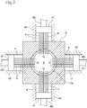
- FIG. 2 is a cross-sectional view of the gear pump extruding machine taken along line II-II of FIG. 1 .
- the gear pump extruding machine 1 includes a screw feeder 10, a gear pump 20, and a die 30 that are successively arranged in the direction along which a rubber material as a viscous material flows.
- the screw feeder 10 supplies the rubber material to the gear pump 20 while kneading the same in an elongate tubular casing 11 upon rotation of an elongate screw 12 therein.
- the tubular casing 11 of the screw feeder 10 has a hopper 11h provided on an upstream side thereof, through which the rubber material as the viscous material is introduced into the tubular casing 11.
- the gear pump 20 includes a pair of upper and lower gears 22a and 22b held in mesh with each other and fitted in a gear pump case 21.
- the gear pump 20 has an inlet side facing the outlet side of the screw feeder 10.
- the pair of upper and lower gears 22a and 22b rotate in respective opposite directions, their gear teeth bite and feed the rubber material supplied from the screw feeder 10 at a constant rate along upper and lower inner peripheral surfaces of the gear pump case 21, and send the rubber material at a constant rate to the die 30 that is provided on the outlet side of the gear pump 20.
- the die 30 provided on the outlet side of the gear pump 20 serves to mold the rubber material sent at the constant rate from the gear pump 20 into a predetermined cross-sectional shape and discharge the molded rubber material.
- An extruded product extruded and discharged from the die 30 of the gear pump extruding machine is extruded as a ribbon strip in the form of a narrow web.
- the gear pump extruding machine 1 includes an outer peripheral wall 15 in the shape of a square outer wall (see FIG. 2 ) defining therein part of a fluid communication channel S (space illustrated stippled in FIG. 1 ) that keeps the screw feeder 10 and the gear pump 20 in fluid communication with each other.
- the outer peripheral wall 15 has an inner peripheral surface that defines a hole with a conical inner surface 15t that is slightly tapered toward the gear pump 20.
- the outer peripheral wall 15 is a member separate from the screw feeder 10 and the gear pump 20.
- pin groups G each including an array of parallel slender pins p as small-diameter cylindrical protrusive members, are supported individually on upper, lower, left, and right portions of the square outer wall of the outer peripheral wall 15, and extend inward from respective outer surfaces of the square outer wall through the conical inner surface 15t and protrude into the fluid communication channel S.
- the pin groups G include a pair of vertical pin groups G that face each other vertically and a pair of lateral pin groups G that face each other horizontally.
- the pins p of each of the pin groups G have proximal ends protruding outward of the outer peripheral wall 15 and embedded in a common slider 41 for movement in unison with each other.
- the slider 41 is slidingly translated in a rectangular tubular body 42 for moving the pins p of each of the pin groups G altogether forward and rearward in the fluid communication channel S.
- the pins p moving with their proximal ends embedded in the sliders 41 are provided as mechanisms of the respective pin groups G that are disposed at four circumferentially equally spaced positions around the fluid communication channel S, so that the sliders 41 are slidable radially of the fluid communication channel S in respective upward, downward, leftward, and rightward directions.
- the sliders 41 are fixed to the distal ends of respective piston rods 45r of hydraulic cylinders 45 ( FIG. 1 ). When the hydraulic cylinders 45 are actuated, their piston rods 45r move the sliders 41 slidingly din the radial directions.
- the distance by which the pins p of the pin groups G protrude into the fluid communication channel S can be changed by controlling the hydraulic cylinders 45 in operation to control the back-and-forth movement of a cylinder rod 35r.
- the volume V of the fluid communication channel S is reduced by the distance by which the pins p move forward to protrude into the fluid communication channel S. Therefore, when the pins p of the four pin groups G protrude into the fluid communication channel S, the volume V of the fluid communication channel S is reduced by the total of the distances by which the pins p of the pin groups G move forward to protrude into the fluid communication channel S. In other words, the volume V of the fluid communication channel S is changed by the distances by which the pins p of the four pin groups G move forward to protrude into the fluid communication channel S.
- the pressure in the fluid communication channel S through which the rubber material flows is of a value determined by the quality of the rubber material.
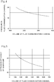
- FIG. 4 is a graph illustrating changes in the pressure Ps in the fluid communication channel S with a rubber material of certain quality flowing therethrough, when the distances by which the pins p protrude into the fluid communication channel S are changed to vary the volume V of the fluid communication channel S, while the screw 12 of the screw feeder 10 and the gears 22a and 22b of the gear pump 20 are rotating at respective predetermined rotational speeds.
- the graph has a horizontal axis representing the volume V (cm 3 ) of the fluid communication channel S and a vertical axis the pressure Ps (MPa) in the fluid communication channel S.
- the pressure on the inlet side of the gear pump 20 is changed by controlling the distances by which the pins p protrude into the fluid communication channel S to change the volume V of the fluid communication channel S, thereby changing the gear pump extrusion efficiency Ep to adjust the rate at which the rubber material is extruded from the die 30 of the gear pump extruding machine 1.
- FIG. 5 is a graph illustrating changes in the gear pump extrusion efficiency Ep (%) at the time the volume V (cm 3 ) of the fluid communication channel S is changed.
- the graph has a horizontal axis representing the volume V of the fluid communication channel S and a vertical axis the gear pump extrusion efficiency Ep.
- the four hydraulic cylinders 45 are actuated by a cylinder actuating mechanism 55, which is controlled by a controller 50.
- a pressure sensor 46 is inserted into the fluid communication channel S that keeps the screw feeder 10 and the gear pump 20 in fluid communication with each other.
- a detection signal that is detected by the pressure sensor 46 as indicative of the pressure in the fluid communication channel S is input to the controller 50.
- the controller 50 includes a memory 51 storing data which represent the results of preliminarily conducted measurements of the relationship between pressures in the fluid communication channel S and rates at which rubber materials are extruded.
- the pressure in the fluid communication channel S corresponding to the determined rate is extracted from the data stored in the memory 51 in advance and established as a target pressure.
- the controller 50 controls the cylinder actuating mechanism 55 to actuate the four hydraulic cylinders 45 to adjust the distances by which the pins p protrude into the fluid communication channel S, so that the pressure in the fluid communication channel S will reach the target pressure.
- the controller 50 reads the pressure in the fluid communication channel S that is detected by the pressure sensor 46, compares the detected pressure with the target pressure, and feedback-controls the cylinder actuating mechanism 55 to adjust the distances by which the pins p protrude into the fluid communication channel S, i.e., the volume V of the fluid communication channel S, in order to make the detected pressure closer to the target pressure.
- FIG. 2 illustrates the gear pump extruding machine 1 in a state in which the distances by which the pins p protrude into the fluid communication channel S are small.
- the pins p of the upper, lower, left, and right pin groups G have their distal ends protruding slightly into the fluid communication channel S, so that the fluid communication channel S is open largely in its central region. Therefore, the volume V of the fluid communication channel S is made large.
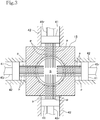
- FIG. 3 illustrates the gear pump extruding machine 1 in a state in which the pins p of the upper, lower, left, and right pin groups G have moved forward and protruded largely into the fluid communication channel S from the state illustrated in FIG. 2 .
- the pins p of the left and right pin groups G are stopped with appropriate open space left therebetween and the pins p of the upper and lower pin groups G are positioned in the open space. Therefore, the volume V of the fluid communication channel S is small.
- the controller 50 should preferably include a system for limiting the distances by which the other pair of pin groups G move forward and protrude so as not to obstruct the first-mentioned pair of pin groups G as they move forward and protrude.
- the pressure in the fluid communication channel S i.e., the pressure on the inlet side of the gear pump 20 (the pressure Ps in the fluid communication channel S) is changed to vary the rate at which the rubber material is extruded from the gear pump extruding machine 1. Consequently, the rubber material is not warmed excessively, and the extruded product is of a quality that is maintained at a high level.
- the rubber material is expected to be warmed adequately due to limited heat generated in the fluid communication channel S, resulting in a contribution to an increase in the quality of the extruded product.
- the gear pump extruding machine 1 offers the following advantages.
- the pressure in the fluid communication channel S is changed when the distances by which the pins p protrude into the fluid communication channel S are changed to vary the volume V of the fluid communication channel S, the pressure in the fluid communication channel S can be changed to adjust the rate at which the rubber material is extruded, without controlling the rotational speed of the screw 12 of the screw feeder 10, by controlling the cylinder actuating mechanism 55 to control the distances by which the pins p protrude into the fluid communication channel S.
- Productivity is increased and the quality of the extruded product is maintained at a high level by avoiding excessive warming of the rubber material.
- the rubber material is expected to be warmed adequately due to limited heat generated in the fluid communication channel S by the pins p protruding into the fluid communication channel S, resulting in a contribution to an increase in the quality of the extruded product.
- the pins p extend inward from the outside of the outer peripheral wall 15 around the fluid communication channel S and protrude into the fluid communication channel S, the pins p can be linearly moved by the hydraulic cylinders 45, and the actuating mechanism can be simplified.
- the hole extending through the outer peripheral wall 15 as part of the fluid communication channel S may be a circular hole. It is thus easy to machine and manufacture the pins p and the outer peripheral wall 15.
- the pin groups G of the pins p are circumferentially equally spaced around the fluid communication channel S in the outer peripheral wall 15, the rubber material is prevented from being disturbed and flowing unevenly in the fluid communication channel S, but can flow smoothly therein.
- the small-diameter slender pins p are actuated in unison with each other in each of the pin groups G arrayed parallel to each other. Consequently, the mechanism in which the pins p are actuated by the hydraulic cylinder 45 is simplified for a reduction in the cost.
- the rate of the rubber material that is bitten by the gear teeth of the gears 22a and 22b of the gear pump 20 remains essentially unchanged even when the distances by which the pins p arranged parallel to each other protrude are changed. Accordingly, the rate at which the rubber material is extruded can be adjusted to a nicety simply by controlling the pressure in the fluid communication channel S.
- the volume V of the fluid communication channel S is changed by controlling the distances by which the pins p protrude into the fluid communication channel S.
- the volume V of the fluid communication channel S may be changed by controlling the number of pins p that protrude into the fluid communication channel S.
- each pin p or pins p of each pin group G is provided with the slider 41 and the hydraulic cylinder 45. If each of pins p is separately slidable, then there are required controls for limiting the distances by which some pins p move forward and protrude in order to avoid physical interference at the time when pins p extending in crossing directions move forward and protrude.
- the pin groups G each including small-diameter slender pins p arrayed parallel to each other are upper, lower, left, and right pin groups.
- pins p in the form of larger-diameter cylindrical members or prismatic rod-shaped members may be circumferentially equally spaced around the fluid communication channel S in the outer peripheral wall 15 for protrusion into the fluid communication channel S.
- the outer peripheral wall 15 is of a square shape in the embodiment, the outer peripheral wall 15 may be of any shape including a circular shape.
- the pins p extending through the outer peripheral wall 15 are provided in the four pin groups G in the embodiment, the number of pin groups G may be less than four or more than four. If the number of pins p and the number of pin groups G are larger, then it is more likely for the distal ends of the pins p to physically interfere with each other when they are moved forward.
- the hydraulic cylinders are used to actuate the protrusive members such as pins p, etc.
- cylinders such as electromagnetic cylinders other than hydraulic cylinders or electric motors may be used to actuate them.
Landscapes
- Engineering & Computer Science (AREA)
- Mechanical Engineering (AREA)
- Extrusion Moulding Of Plastics Or The Like (AREA)
- Details And Applications Of Rotary Liquid Pumps (AREA)
- Rotary Pumps (AREA)
Abstract
Description
- The present invention relates to a gear pump extruding machine as a viscous material extruding machine that is provided with a gear pump.
- A gear pump extruding machine includes a screw feeder in which a screw rotates to feed a rubber material while kneading the same, a gear pump provided at the outlet side of the screw feeder and having a pair of gears for feeding the rubber material at a constant rate, and a die provided at the outlet side of the gear pump, for ejecting the rubber material while shaping the same. The gear pump extruding machine extrudes the rubber material while forming it into the desired profile.
- It is known that the rate at which the rubber material is extruded from the die of the gear pump extruding machine is determined by the gear pump extrusion efficiency of the gear pump that delivers the rubber material at the constant rate, and that the gear pump extrusion efficiency is affected by the quality of the rubber material and varies depending on the pressure on the inlet side of the gear pump (the pressure in a fluid communication channel that keeps the screw feeder and the gear pump in fluid communication with each other).
- Therefore, when the rate at which the rubber material is extruded is changed, it is customary to adjust the pressure on the inlet side of the gear pump in order to set the gear pump extrusion efficiency to a value for achieving the changed rate at which the rubber material is extruded.
- Since the pressure on the inlet side of the gear pump increases as the rotational speed of the screw of the screw feeder increases, it has been proposed to control the rotational speed of the screw of the screw feeder for adjusting the pressure on the inlet side of the gear pump (see, for example, PATENT DOCUMENT 1).
- [PATENT DOCUMENT 1]
JP 2002-178392 A - PATENT DOCUMENT 1 discloses a gear pump extruding machine in which a target inlet pressure for the gear pump is preset with respect to the rate at which the rubber material is extruded, and the pressure detected by a pressure sensor disposed at the inlet side of the gear pump is fed back to control the rotational speed of the screw in order to attain the target inlet pressure.
- The screw feeder feeds a viscous material while kneading the same upon rotation of the screw. When the screw rotates, it exerts a shear stress on the viscous material, causing the viscous material to generate heat and to be plasticized (due to the warming thereof) for better processability. However, since heating occurs entirely in the elongate tubular casing of the screw feeder, the warming tends to be excessive.
- Providing the rotational speed of the screw of the screw feeder is controlled in order to change the rate at which the rubber material is extruded, as described above, particularly when the screw is accelerated in rotation, the warming is likely to become more excessive. Then, if the viscous material is an unvulcanized rubber material, the rubber material will be vulcanized to an excessive degree, tending to become lower in quality.
- According to the present invention, attention is focused on the fact that the pressure in the fluid communication channel that keeps the screw feeder and the gear pump in the fluid communication with each other, i.e., the pressure on the inlet side of the gear pump device, can be changed by changing the volume of the fluid communication channel, and the pressure on the inlet side of the gear pump is changed to adjust the rate at which the viscous material is extruded by controlling the volume of the fluid communication channel, rather than controlling the rotational speed of the screw which is liable to make the viscous material warmed excessively.
- Therefore, it is an object of the present invention to provide a gear pump extruding machine in which the volume of a fluid communication channel is changed to adjust the rate at which a viscous material is extruded, preventing the viscous material from being warmed excessively at all times.
- In order to achieve the above object, there is provided in accordance with the present invention a gear pump extruding machine for extruding a viscous material, having a screw feeder including a tubular casing and a screw disposed in the tubular casing, for supplying the viscous material while kneading same upon rotation of the screw, a gear pump including a pair of gears provided on an outlet side of the screw feeder with a fluid communication channel interposed therebetween, to deliver the viscous material with the gears, and a die disposed on an outlet side of the gear pump, for molding and discharging the viscous material, the gear pump extruding machine including protrusive members movable forward and rearward to protrude into the fluid communication channel which keeps the screw feeder and the gear pump in fluid communication with each other, to thereby change the volume of the fluid communication channel, an actuator for moving the protrusive members forward and rearward in the fluid communication channel, and a controller for controlling the actuator, wherein the controller is operable to control the actuator to move the protrusive members forward and rearward to thereby change the volume of the fluid communication channel in order to set the pressure in the fluid communication channel to a predetermined pressure depending on the rate at which the viscous material is extruded.
- With this arrangement, since the pressure in the fluid communication channel is changed when the protrusive members protrude forward and rearward in the fluid communication channel to change the volume of the fluid communication channel, the pressure in the fluid communication channel can be changed to adjust the rate at which the rubber material is extruded, without controlling the rotational speed of the screw of the screw device, by controlling the actuator to control the distance by which the protrusive members protrude in the fluid communication channel. Productivity is thus increased and the quality of the extruded product is maintained at a high level by avoiding excessive warming of the viscous material.
- The viscous material is expected to be warmed adequately due to limited heat generated in the fluid communication channel by the protrusive members protruding into the fluid communication channel, resulting in a contribution to increase in the quality of the extruded product.
- According to the present invention, the protrusive members may include a plurality of rod-shaped members extending inward from outside through an outer peripheral wall that defines the fluid communication channel therein and protruding into the fluid communication channel.
- With this arrangement, since the rod-shaped members extend inward from outside through the outer peripheral wall that defines the fluid communication channel therein and protrude into the fluid communication channel and move forward and rearward, the rod-shaped members may be moved linearly by the actuator, and may be simplified.
- According to the present invention, the rod-shaped members may be cylindrical in shape.
- With this arrangement, since the rod-shaped members are each cylindrical in shape, the viscous material flowing through the fluid communication channel can flow smoothly without being partially stagnated by the rod-shaped members. The hole extending through the outer peripheral wall as part of the fluid communication channel may be a circular hole. It is thus easy to machine and manufacture the rod-shaped members and the outer peripheral wall.
- According to the present invention, the rod-shaped members are preferably disposed in circumferentially equally spaced positions around the fluid communication channel in the outer peripheral wall.
- With this arrangement, since the rod-shaped members are circumferentially equally spaced around the fluid communication channel in the outer peripheral wall, the viscous material is prevented from being disturbed and flowing unevenly in the fluid communication channel, but can flow smoothly therein.
- According to a preferred embodiment of the present invention, the rod-shaped members are small-diameter slender pins, the pins are arrayed parallel to each other and arranged in a plurality of pin groups, the pin groups being disposed in circumferentially equally spaced positions around the fluid communication channel in the outer peripheral wall that defines the fluid communication channel therein, and the actuator is provided in combination with each of the pin groups for actuating the pins of each of the pin groups in unison with each other.
- With this arrangement, the small-diameter slender pins as the rod-shaped members are actuated in unison with each other in each of the pin groups arrayed parallel to each other. Consequently, the mechanism in which the pins are actuated by the actuator is simplified for a reduction in the cost.
- The rate of the viscous material that is bitten by the gear teeth of the gears of the gear pump remains essentially unchanged even when the distances by which the pins arranged parallel to each other protrude are changed. Accordingly, the rate at which the viscous material is extruded can be adjusted to a nicety simply by controlling the pressure in the fluid communication channel.
- In an embodiment of the present invention, the outer peripheral wall that defines the fluid communication channel therein is disposed between the screw feeder and the gear pump, and the actuator for moving the protrusive members forward and rearward in the fluid communication channel is disposed outwardly of the outer peripheral wall, thereby obtaining a preferable overall arrangement.
- Furthermore, the protrusive members include a first pair of pin groups facing each other in a diametrical direction across the fluid communication channel and a second pair of pin groups facing each other in another diametrical direction across the fluid communication channel, and the controller includes a system for limiting the distances by which the second pair of pin groups move forward and protrude so as not to obstruct the first pair of pin groups as the first pair of pin groups move forward and protrude, thereby avoiding the pin groups from physically interfering with each other when the pin groups are moved forwardly.
- According to the present invention, the controller controls the actuator to control the distance by which the protrusive members protrude in the fluid communication channel to thereby change the pressure in the fluid communication channel so as to adjust the rate at which the viscous material is extruded, while avoiding excessive warming of the viscous material which would otherwise be caused by controlling the rotational speed of the screw of the screw device.
-
-
FIG. 1 is a schematic view of a gear pump extruding machine according to an embodiment of the present invention; -
FIG. 2 is a cross-sectional view of the gear pump extruding machine, taken along line II-II ofFIG. 1 ; -
FIG. 3 is a cross-sectional view illustrating the gear pump extruding machine in another state; -
FIG. 4 is a graph illustrating changes in pressure in a fluid communication channel with respect to changes in volume of the fluid communication channel; and -
FIG. 5 is a graph illustrating changes in extrusion efficiency of a gear pump with respect to changes in volume of the fluid communication channel. - An embodiment of the present invention will be described below with reference to the drawings.
- A gear pump extruding machine 1 according to the present embodiment serves to extrusion-mold a ribbon strip in the form of a narrow web for manufacturing a tire component.
-
FIG. 1 is a schematic view of the entirety of the gear pump extruding machine 1, andFIG. 2 is a cross-sectional view of the gear pump extruding machine taken along line II-II ofFIG. 1 . - As illustrated in
FIG. 1 , the gear pump extruding machine 1 includes ascrew feeder 10, agear pump 20, and adie 30 that are successively arranged in the direction along which a rubber material as a viscous material flows. - The
screw feeder 10 supplies the rubber material to thegear pump 20 while kneading the same in an elongatetubular casing 11 upon rotation of anelongate screw 12 therein. Thetubular casing 11 of thescrew feeder 10 has ahopper 11h provided on an upstream side thereof, through which the rubber material as the viscous material is introduced into thetubular casing 11. - The
gear pump 20 includes a pair of upper andlower gears gear pump 20 has an inlet side facing the outlet side of thescrew feeder 10. When the pair of upper andlower gears screw feeder 10 at a constant rate along upper and lower inner peripheral surfaces of the gear pump case 21, and send the rubber material at a constant rate to thedie 30 that is provided on the outlet side of thegear pump 20. - The die 30 provided on the outlet side of the
gear pump 20 serves to mold the rubber material sent at the constant rate from thegear pump 20 into a predetermined cross-sectional shape and discharge the molded rubber material. - An extruded product extruded and discharged from the die 30 of the gear pump extruding machine is extruded as a ribbon strip in the form of a narrow web.
- The gear pump extruding machine 1 includes an outer
peripheral wall 15 in the shape of a square outer wall (seeFIG. 2 ) defining therein part of a fluid communication channel S (space illustrated stippled inFIG. 1 ) that keeps thescrew feeder 10 and thegear pump 20 in fluid communication with each other. The outerperipheral wall 15 has an inner peripheral surface that defines a hole with a conicalinner surface 15t that is slightly tapered toward thegear pump 20. The outerperipheral wall 15 is a member separate from thescrew feeder 10 and thegear pump 20. - As illustrated in
FIG. 2 , pin groups G, each including an array of parallel slender pins p as small-diameter cylindrical protrusive members, are supported individually on upper, lower, left, and right portions of the square outer wall of the outerperipheral wall 15, and extend inward from respective outer surfaces of the square outer wall through the conicalinner surface 15t and protrude into the fluid communication channel S. In the illustrated embodiment, the pin groups G include a pair of vertical pin groups G that face each other vertically and a pair of lateral pin groups G that face each other horizontally. - The pins p of each of the pin groups G have proximal ends protruding outward of the outer
peripheral wall 15 and embedded in acommon slider 41 for movement in unison with each other. Theslider 41 is slidingly translated in a rectangulartubular body 42 for moving the pins p of each of the pin groups G altogether forward and rearward in the fluid communication channel S. - The pins p moving with their proximal ends embedded in the
sliders 41 are provided as mechanisms of the respective pin groups G that are disposed at four circumferentially equally spaced positions around the fluid communication channel S, so that thesliders 41 are slidable radially of the fluid communication channel S in respective upward, downward, leftward, and rightward directions. Thesliders 41 are fixed to the distal ends ofrespective piston rods 45r of hydraulic cylinders 45 (FIG. 1 ). When thehydraulic cylinders 45 are actuated, theirpiston rods 45r move thesliders 41 slidingly din the radial directions. - Therefore, when the
sliders 41 are slid in the radial directions by the actuatedhydraulic cylinders 45, the pins p whose proximal ends are embedded in thesliders 41 are moved back and forth in the fluid communication channel S. - The distance by which the pins p of the pin groups G protrude into the fluid communication channel S can be changed by controlling the
hydraulic cylinders 45 in operation to control the back-and-forth movement of a cylinder rod 35r. - When the pins p move forward to protrude into the fluid communication channel S, the volume V of the fluid communication channel S is reduced by the distance by which the pins p move forward to protrude into the fluid communication channel S. Therefore, when the pins p of the four pin groups G protrude into the fluid communication channel S, the volume V of the fluid communication channel S is reduced by the total of the distances by which the pins p of the pin groups G move forward to protrude into the fluid communication channel S. In other words, the volume V of the fluid communication channel S is changed by the distances by which the pins p of the four pin groups G move forward to protrude into the fluid communication channel S.
- Providing the volume V of the fluid communication channel S is constant, if the gear pump extruding machine 1 is in steady operation, making the rotational speed of the
screw 12 of thescrew feeder 10 constant and also making the rotational speed of thegears gear pump 20 constant, then the pressure in the fluid communication channel S through which the rubber material flows is of a value determined by the quality of the rubber material. - If the distances by which the pins p of the four pin groups G protrude into the fluid communication channel S are changed when the gear pump extruding machine 1 is in steady operation, to thus change the volume V of the fluid communication channel S, the pressure in the fluid communication channel S is also changed.
-
FIG. 4 is a graph illustrating changes in the pressure Ps in the fluid communication channel S with a rubber material of certain quality flowing therethrough, when the distances by which the pins p protrude into the fluid communication channel S are changed to vary the volume V of the fluid communication channel S, while thescrew 12 of thescrew feeder 10 and thegears gear pump 20 are rotating at respective predetermined rotational speeds. - The graph has a horizontal axis representing the volume V (cm3) of the fluid communication channel S and a vertical axis the pressure Ps (MPa) in the fluid communication channel S. As the distances by which the pins p protrude into the fluid communication channel S increase, the volume V of the fluid communication channel S represented by the horizontal axis decreases, and as the volume V of the fluid communication channel S decreases, the pressure Ps in the fluid communication channel S increases as illustrated in
FIG. 4 . - Since the pressure in the fluid communication channel S is the same as the pressure on the inlet side of the
gear pump 20, the pressure on the inlet side of thegear pump 20 is changed by controlling the distances by which the pins p protrude into the fluid communication channel S to change the volume V of the fluid communication channel S, thereby changing the gear pump extrusion efficiency Ep to adjust the rate at which the rubber material is extruded from thedie 30 of the gear pump extruding machine 1. -
FIG. 5 is a graph illustrating changes in the gear pump extrusion efficiency Ep (%) at the time the volume V (cm3) of the fluid communication channel S is changed. The graph has a horizontal axis representing the volume V of the fluid communication channel S and a vertical axis the gear pump extrusion efficiency Ep. - As the distances by which the pins p protrude into the fluid communication channel S increase and the volume V of the fluid communication channel S decreases, the pressure Ps in the fluid communication channel S increases, whereby the gear pump extrusion efficiency Ep is increased.
- Consequently, as the volume V of the fluid communication channel S decreases, the pressure Ps in the fluid communication channel S increases thereby to increase the gear pump extrusion efficiency Ep, increasing the rate at which the rubber material is extruded.
- Referring to
FIG. 1 , the fourhydraulic cylinders 45 are actuated by acylinder actuating mechanism 55, which is controlled by acontroller 50. - A
pressure sensor 46 is inserted into the fluid communication channel S that keeps thescrew feeder 10 and thegear pump 20 in fluid communication with each other. A detection signal that is detected by thepressure sensor 46 as indicative of the pressure in the fluid communication channel S is input to thecontroller 50. - The
controller 50 includes amemory 51 storing data which represent the results of preliminarily conducted measurements of the relationship between pressures in the fluid communication channel S and rates at which rubber materials are extruded. - When a rate at which a rubber material is to be extruded from the gear pump extruding machine 1 is determined from the speed of a line in which the gear pump extruding machine 1 is incorporated, the pressure in the fluid communication channel S corresponding to the determined rate is extracted from the data stored in the
memory 51 in advance and established as a target pressure. - The
controller 50 controls thecylinder actuating mechanism 55 to actuate the fourhydraulic cylinders 45 to adjust the distances by which the pins p protrude into the fluid communication channel S, so that the pressure in the fluid communication channel S will reach the target pressure. - Specifically, the
controller 50 reads the pressure in the fluid communication channel S that is detected by thepressure sensor 46, compares the detected pressure with the target pressure, and feedback-controls thecylinder actuating mechanism 55 to adjust the distances by which the pins p protrude into the fluid communication channel S, i.e., the volume V of the fluid communication channel S, in order to make the detected pressure closer to the target pressure. -
FIG. 2 illustrates the gear pump extruding machine 1 in a state in which the distances by which the pins p protrude into the fluid communication channel S are small. The pins p of the upper, lower, left, and right pin groups G have their distal ends protruding slightly into the fluid communication channel S, so that the fluid communication channel S is open largely in its central region. Therefore, the volume V of the fluid communication channel S is made large. -
FIG. 3 illustrates the gear pump extruding machine 1 in a state in which the pins p of the upper, lower, left, and right pin groups G have moved forward and protruded largely into the fluid communication channel S from the state illustrated inFIG. 2 . - In order to avoid physical interference between the pins p of the upper and lower pin groups G and the pins p of the left and right pin groups G, the pins p of the left and right pin groups G are stopped with appropriate open space left therebetween and the pins p of the upper and lower pin groups G are positioned in the open space. Therefore, the volume V of the fluid communication channel S is small.
- Thus, in order to prevent a pair of pin groups G that face each other diametrically across the fluid communication channel S from physically interfering, when moving forward and protruding, with another pair of pin groups G that face each other diametrically across the fluid communication channel S, the
controller 50 should preferably include a system for limiting the distances by which the other pair of pin groups G move forward and protrude so as not to obstruct the first-mentioned pair of pin groups G as they move forward and protrude. - By thus controlling the distances by which the pins p protrude into the fluid communication channel S to change the volume V of the fluid communication channel S, the pressure in the fluid communication channel S, i.e., the pressure on the inlet side of the gear pump 20 (the pressure Ps in the fluid communication channel S), is changed to vary the rate at which the rubber material is extruded from the gear pump extruding machine 1. Consequently, the rubber material is not warmed excessively, and the extruded product is of a quality that is maintained at a high level.
- Inasmuch as the kneading of the rubber material is promoted by a change in the pressure in the fluid communication channel S which is caused by the pins p protruding into the fluid communication channel S, the rubber material is expected to be warmed adequately due to limited heat generated in the fluid communication channel S, resulting in a contribution to an increase in the quality of the extruded product.
- The gear pump extruding machine 1 according to the embodiment of the present invention described in detail above offers the following advantages.
- Since the pressure in the fluid communication channel S is changed when the distances by which the pins p protrude into the fluid communication channel S are changed to vary the volume V of the fluid communication channel S, the pressure in the fluid communication channel S can be changed to adjust the rate at which the rubber material is extruded, without controlling the rotational speed of the
screw 12 of thescrew feeder 10, by controlling thecylinder actuating mechanism 55 to control the distances by which the pins p protrude into the fluid communication channel S. Productivity is increased and the quality of the extruded product is maintained at a high level by avoiding excessive warming of the rubber material. - The rubber material is expected to be warmed adequately due to limited heat generated in the fluid communication channel S by the pins p protruding into the fluid communication channel S, resulting in a contribution to an increase in the quality of the extruded product.
- Since the pins p extend inward from the outside of the outer
peripheral wall 15 around the fluid communication channel S and protrude into the fluid communication channel S, the pins p can be linearly moved by thehydraulic cylinders 45, and the actuating mechanism can be simplified. - Because the pins p are cylindrical in shape each, the rubber member flowing through the fluid communication channel S can flow smoothly without being partially stagnated by the pins p. The hole extending through the outer
peripheral wall 15 as part of the fluid communication channel S may be a circular hole. It is thus easy to machine and manufacture the pins p and the outerperipheral wall 15. - Since the pin groups G of the pins p are circumferentially equally spaced around the fluid communication channel S in the outer
peripheral wall 15, the rubber material is prevented from being disturbed and flowing unevenly in the fluid communication channel S, but can flow smoothly therein. - The small-diameter slender pins p are actuated in unison with each other in each of the pin groups G arrayed parallel to each other. Consequently, the mechanism in which the pins p are actuated by the
hydraulic cylinder 45 is simplified for a reduction in the cost. - The rate of the rubber material that is bitten by the gear teeth of the
gears gear pump 20 remains essentially unchanged even when the distances by which the pins p arranged parallel to each other protrude are changed. Accordingly, the rate at which the rubber material is extruded can be adjusted to a nicety simply by controlling the pressure in the fluid communication channel S. - The gear pump extruding machine according to the embodiment of the present invention has been described above. The present invention is not limited to the above embodiment, but covers many changes and modifications made thereto within the scope of the invention.
- For example, in the present embodiment, the volume V of the fluid communication channel S is changed by controlling the distances by which the pins p protrude into the fluid communication channel S. However, the volume V of the fluid communication channel S may be changed by controlling the number of pins p that protrude into the fluid communication channel S. According to such a modification, each pin p or pins p of each pin group G is provided with the
slider 41 and thehydraulic cylinder 45. If each of pins p is separately slidable, then there are required controls for limiting the distances by which some pins p move forward and protrude in order to avoid physical interference at the time when pins p extending in crossing directions move forward and protrude. - In the present embodiment, the pin groups G each including small-diameter slender pins p arrayed parallel to each other are upper, lower, left, and right pin groups. However, pins p in the form of larger-diameter cylindrical members or prismatic rod-shaped members may be circumferentially equally spaced around the fluid communication channel S in the outer
peripheral wall 15 for protrusion into the fluid communication channel S. Furthermore, although the outerperipheral wall 15 is of a square shape in the embodiment, the outerperipheral wall 15 may be of any shape including a circular shape. Although the pins p extending through the outerperipheral wall 15 are provided in the four pin groups G in the embodiment, the number of pin groups G may be less than four or more than four. If the number of pins p and the number of pin groups G are larger, then it is more likely for the distal ends of the pins p to physically interfere with each other when they are moved forward. - In the embodiment, the hydraulic cylinders are used to actuate the protrusive members such as pins p, etc., cylinders such as electromagnetic cylinders other than hydraulic cylinders or electric motors may be used to actuate them.
-
- 1···Gear pump extruding machine,
- 10···Screw feeder, 11···Tubular casing, 11h···Hopper, 12···Screw,
- 15···Outer peripheral wall, S···Fluid communication channel, p···Pin, G···Pin group,
- 20...Gear pump, 21...Gear pump case, 22a, 22b···Gear, 30···Die,
- 41···Slider, 45···Hydraulic cylinder, 46···Pressure sensor,
- 50···Controller, 51···Memory, 55···Cylinder actuating mechanism.
Claims (7)
- A gear pump extruding machine for extruding a viscous material, having a screw feeder including a tubular casing and a screw disposed in the tubular casing, for supplying the viscous material while kneading same upon rotation of the screw, a gear pump including a pair of gears provided on an outlet side of said screw feeder with a fluid communication channel interposed therebetween, for delivering the viscous material with the gears, and a die disposed on an outlet side of said gear pump, for molding and discharging the viscous material, said gear pump extruding machine comprising:protrusive members movable forward and rearward to protrude into said fluid communication channel which keeps said screw feeder and said gear pump in fluid communication with each other, to thereby change said fluid communication channel in volume ;an actuator for moving said protrusive members forward and rearward in said fluid communication channel; anda controller for controlling said actuator,wherein said controller is operable to control said actuator to move said protrusive members forward and rearward to thereby change the volume of said fluid communication channel in order to set the pressure in said fluid communication channel to a predetermined pressure depending on the rate at which said viscous material is extruded.
- The gear pump extruding machine according to claim 1, wherein said protrusive members include a plurality of rod-shaped members extending inward from outside through an outer peripheral wall that defines said fluid communication channel therein and protruding into said fluid communication channel.
- The gear pump extruding machine according to claim 2, wherein said rod-shaped members are cylindrical in shape.
- The gear pump extruding machine according to claim 3, wherein said rod-shaped members are disposed in circumferentially equally spaced positions around said fluid communication channel in said outer peripheral wall.
- The gear pump extruding machine according to claim 3, wherein:said rod-shaped members are small-diameter slender pins;said pins are arrayed parallel to each other and arranged in a plurality of pin groups, said pin groups being disposed in circumferentially equally spaced positions around said fluid communication channel in said outer peripheral wall defining said fluid communication channel therein; andsaid actuator is provided in combination with each of said pin groups for actuating the pins of each of the pin groups in unison with each other.
- The gear pump extruding machine according to claim 2, wherein said outer peripheral wall defining said fluid communication channel therein is disposed between said screw feeder and said gear pump, and said actuator for moving said protrusive member forward and rearward in said fluid communication channel is disposed outwardly of said outer peripheral wall.
- The gear pump extruding machine according to claim 5, wherein said protrusive members include a first pair of pin groups facing each other in a diametrical direction across said fluid communication channel and a second pair of pin groups facing each other in another diametrical direction across said fluid communication channel, and said controller includes a system for limiting the distances by which the second pair of pin groups move forward and protrude so as not to obstruct the first pair of pin groups as the first pair of pin groups move forward and protrude.
Applications Claiming Priority (2)
| Application Number | Priority Date | Filing Date | Title |
|---|---|---|---|
| JP2015076127A JP2016196105A (en) | 2015-04-02 | 2015-04-02 | Gear pump type extruder |
| PCT/JP2016/059710 WO2016158789A1 (en) | 2015-04-02 | 2016-03-25 | Gear pump extruding machine |
Publications (3)
| Publication Number | Publication Date |
|---|---|
| EP3278951A1 true EP3278951A1 (en) | 2018-02-07 |
| EP3278951A4 EP3278951A4 (en) | 2018-03-14 |
| EP3278951B1 EP3278951B1 (en) | 2019-06-12 |
Family
ID=57005757
Family Applications (1)
| Application Number | Title | Priority Date | Filing Date |
|---|---|---|---|
| EP16772670.2A Active EP3278951B1 (en) | 2015-04-02 | 2016-03-25 | Gear pump extruding machine |
Country Status (5)
| Country | Link |
|---|---|
| US (1) | US20180050479A1 (en) |
| EP (1) | EP3278951B1 (en) |
| JP (1) | JP2016196105A (en) |
| CN (1) | CN107428062B (en) |
| WO (1) | WO2016158789A1 (en) |
Cited By (1)
| Publication number | Priority date | Publication date | Assignee | Title |
|---|---|---|---|---|
| IT202000029222A1 (en) | 2020-12-01 | 2022-06-01 | Pirelli | Extrusion method of a semi-finished product in elastomeric material |
Families Citing this family (10)
| Publication number | Priority date | Publication date | Assignee | Title |
|---|---|---|---|---|
| IT201800002860A1 (en) * | 2018-02-20 | 2019-08-20 | Colmec S P A | TWIN-SCREW MIXER-EXTRUDER, INCLUDING CONTROL MEANS OF A MIXING CHAMBER |
| US10532512B2 (en) * | 2018-06-07 | 2020-01-14 | Thermwood Corporation | Additive manufacturing apparatus |
| JP7104351B2 (en) * | 2018-07-26 | 2022-07-21 | ダイキン工業株式会社 | Manufacturing method of resin molded product |
| JP7107127B2 (en) * | 2018-09-20 | 2022-07-27 | 横浜ゴム株式会社 | Rubber extrusion method and apparatus |
| FR3093457A1 (en) * | 2019-03-06 | 2020-09-11 | Compagnie Generale Des Etablissements Michelin | Twin Screw Mixing and Extrusion Machine with Removable Elements |
| DE102019207728A1 (en) * | 2019-05-27 | 2020-12-03 | Continental Reifen Deutschland Gmbh | Device for the extrusion of sulfur-crosslinkable rubber mixtures, the use of the device and a method for producing an extruded, sulfur-crosslinkable rubber mixture |
| CN110435114A (en) * | 2019-08-01 | 2019-11-12 | 南通理工学院 | Co-rotating double-screw structure extruder |
| WO2022076688A1 (en) * | 2020-10-09 | 2022-04-14 | Mackay Michael E | Positive displacement pump material delivery system for additive manufacture |
| CN117484838B (en) * | 2023-12-29 | 2024-03-12 | 常州金纬化工成套设备有限公司 | Extrusion pressure detection device of extruder |
| CN118372457B (en) * | 2024-06-25 | 2024-09-24 | 江苏君华特种高分子材料股份有限公司 | Pressure detection device and polyetheretherketone production process |
Family Cites Families (7)
| Publication number | Priority date | Publication date | Assignee | Title |
|---|---|---|---|---|
| DE2751225C3 (en) * | 1977-11-16 | 1981-08-13 | Werner & Pfleiderer, 7000 Stuttgart | Device with a melt index measuring device arranged after the sieve pack of a screw extruder and a method for regulating the viscosity of melted plastic that is to be molded |
| JPS55137944A (en) * | 1979-04-15 | 1980-10-28 | Matsushita Electric Works Ltd | Extrusion molding machine |
| JPS5698145A (en) * | 1979-12-29 | 1981-08-07 | Sekisui Chem Co Ltd | Pipe-extruder |
| JPS6440517U (en) * | 1987-09-03 | 1989-03-10 | ||
| JP2002178392A (en) * | 2000-12-15 | 2002-06-26 | Hitachi Zosen Corp | Extruder control device and control method |
| JP5574843B2 (en) * | 2010-06-21 | 2014-08-20 | 株式会社ブリヂストン | Unvulcanized rubber extrusion apparatus and extrusion molding method |
| US9216535B2 (en) * | 2011-06-07 | 2015-12-22 | 3M Innovative Properties Company | Slot die position adjustments to facilitate patterned products |
-
2015
- 2015-04-02 JP JP2015076127A patent/JP2016196105A/en active Pending
-
2016
- 2016-03-25 EP EP16772670.2A patent/EP3278951B1/en active Active
- 2016-03-25 CN CN201680019631.5A patent/CN107428062B/en not_active Expired - Fee Related
- 2016-03-25 US US15/557,517 patent/US20180050479A1/en not_active Abandoned
- 2016-03-25 WO PCT/JP2016/059710 patent/WO2016158789A1/en not_active Ceased
Cited By (1)
| Publication number | Priority date | Publication date | Assignee | Title |
|---|---|---|---|---|
| IT202000029222A1 (en) | 2020-12-01 | 2022-06-01 | Pirelli | Extrusion method of a semi-finished product in elastomeric material |
Also Published As
| Publication number | Publication date |
|---|---|
| CN107428062B (en) | 2019-08-23 |
| WO2016158789A1 (en) | 2016-10-06 |
| JP2016196105A (en) | 2016-11-24 |
| EP3278951B1 (en) | 2019-06-12 |
| EP3278951A4 (en) | 2018-03-14 |
| CN107428062A (en) | 2017-12-01 |
| US20180050479A1 (en) | 2018-02-22 |
Similar Documents
| Publication | Publication Date | Title |
|---|---|---|
| EP3278951B1 (en) | Gear pump extruding machine | |
| KR101845096B1 (en) | Kneading extrusion device | |
| WO2019141606A1 (en) | An extruder with axial displacement | |
| RU2012141045A (en) | DEVICE AND METHOD FOR PRODUCTION OF PRODUCTS | |
| US11084200B2 (en) | Silicone extrusion plant, method for silicone extrusion and silicone extrudate produced herewith | |
| US11396120B2 (en) | Rubber extrusion device and method for manufacturing rubber extrudate | |
| CN101112787A (en) | Cord Covering Plant with Moving Die | |
| JP7107127B2 (en) | Rubber extrusion method and apparatus | |
| EP2442960B1 (en) | In an injection unit having a filter, a method of controlling melt pressure in accordance with a target pressure range | |
| CN107405816B (en) | Extruder and method for extruding cord-reinforced tire components | |
| JP5989387B2 (en) | Method for forming cylindrical rubber member | |
| CN101166617B (en) | Method for extruding a polymeric material and extrusion head therefor | |
| JP5683940B2 (en) | Plasticizing equipment | |
| JP6740595B2 (en) | Rubber extrusion equipment | |
| AT523150B1 (en) | Method for influencing a backlog length and / or a screw return speed | |
| EP3584057B1 (en) | Rubber extruder and method for producing rubber extrudate | |
| CN102470596A (en) | A method of controlling multiple injection molding chambers | |
| EP3674070B1 (en) | Rubber extrusion device and method for manufacturing rubber extruded object | |
| CN104822505B (en) | Extrusion blow molding processes and apparatus for carrying out the method | |
| JP4191572B2 (en) | Rubber injection molding system and injection molding vulcanization condition setting method for rubber injection molding system | |
| CN114340863A (en) | Extrusion device and die for extrusion molding | |
| JP2020044774A (en) | Rubber extrusion method and equipment | |
| US6171531B1 (en) | Method for simultaneous control of multiple accumulators | |
| AT516122A1 (en) | Method for dosing plastic granules | |
| JP5761269B2 (en) | Rubber roll manufacturing method |
Legal Events
| Date | Code | Title | Description |
|---|---|---|---|
| STAA | Information on the status of an ep patent application or granted ep patent |
Free format text: STATUS: THE INTERNATIONAL PUBLICATION HAS BEEN MADE |
|
| PUAI | Public reference made under article 153(3) epc to a published international application that has entered the european phase |
Free format text: ORIGINAL CODE: 0009012 |
|
| STAA | Information on the status of an ep patent application or granted ep patent |
Free format text: STATUS: REQUEST FOR EXAMINATION WAS MADE |
|
| 17P | Request for examination filed |
Effective date: 20170929 |
|
| AK | Designated contracting states |
Kind code of ref document: A1 Designated state(s): AL AT BE BG CH CY CZ DE DK EE ES FI FR GB GR HR HU IE IS IT LI LT LU LV MC MK MT NL NO PL PT RO RS SE SI SK SM TR |
|
| AX | Request for extension of the european patent |
Extension state: BA ME |
|
| A4 | Supplementary search report drawn up and despatched |
Effective date: 20180212 |
|
| RIC1 | Information provided on ipc code assigned before grant |
Ipc: B29C 47/08 20060101ALI20180206BHEP Ipc: B29C 47/92 20060101AFI20180206BHEP Ipc: B29C 47/66 20060101ALI20180206BHEP Ipc: B29C 47/36 20060101ALI20180206BHEP |
|
| DAV | Request for validation of the european patent (deleted) | ||
| DAX | Request for extension of the european patent (deleted) | ||
| GRAP | Despatch of communication of intention to grant a patent |
Free format text: ORIGINAL CODE: EPIDOSNIGR1 |
|
| STAA | Information on the status of an ep patent application or granted ep patent |
Free format text: STATUS: GRANT OF PATENT IS INTENDED |
|
| RIC1 | Information provided on ipc code assigned before grant |
Ipc: B29C 47/36 20060101ALI20181206BHEP Ipc: B29C 47/08 20060101ALI20181206BHEP Ipc: B29C 47/66 20060101ALI20181206BHEP Ipc: B29C 47/92 20060101AFI20181206BHEP |
|
| INTG | Intention to grant announced |
Effective date: 20181220 |
|
| GRAS | Grant fee paid |
Free format text: ORIGINAL CODE: EPIDOSNIGR3 |
|
| GRAA | (expected) grant |
Free format text: ORIGINAL CODE: 0009210 |
|
| STAA | Information on the status of an ep patent application or granted ep patent |
Free format text: STATUS: THE PATENT HAS BEEN GRANTED |
|
| AK | Designated contracting states |
Kind code of ref document: B1 Designated state(s): AL AT BE BG CH CY CZ DE DK EE ES FI FR GB GR HR HU IE IS IT LI LT LU LV MC MK MT NL NO PL PT RO RS SE SI SK SM TR |
|
| REG | Reference to a national code |
Ref country code: GB Ref legal event code: FG4D |
|
| REG | Reference to a national code |
Ref country code: CH Ref legal event code: EP |
|
| REG | Reference to a national code |
Ref country code: AT Ref legal event code: REF Ref document number: 1142012 Country of ref document: AT Kind code of ref document: T Effective date: 20190615 |
|
| REG | Reference to a national code |
Ref country code: DE Ref legal event code: R096 Ref document number: 602016015309 Country of ref document: DE |
|
| REG | Reference to a national code |
Ref country code: IE Ref legal event code: FG4D |
|
| REG | Reference to a national code |
Ref country code: NL Ref legal event code: MP Effective date: 20190612 |
|
| REG | Reference to a national code |
Ref country code: LT Ref legal event code: MG4D |
|
| PG25 | Lapsed in a contracting state [announced via postgrant information from national office to epo] |
Ref country code: FI Free format text: LAPSE BECAUSE OF FAILURE TO SUBMIT A TRANSLATION OF THE DESCRIPTION OR TO PAY THE FEE WITHIN THE PRESCRIBED TIME-LIMIT Effective date: 20190612 Ref country code: LT Free format text: LAPSE BECAUSE OF FAILURE TO SUBMIT A TRANSLATION OF THE DESCRIPTION OR TO PAY THE FEE WITHIN THE PRESCRIBED TIME-LIMIT Effective date: 20190612 Ref country code: SE Free format text: LAPSE BECAUSE OF FAILURE TO SUBMIT A TRANSLATION OF THE DESCRIPTION OR TO PAY THE FEE WITHIN THE PRESCRIBED TIME-LIMIT Effective date: 20190612 Ref country code: HR Free format text: LAPSE BECAUSE OF FAILURE TO SUBMIT A TRANSLATION OF THE DESCRIPTION OR TO PAY THE FEE WITHIN THE PRESCRIBED TIME-LIMIT Effective date: 20190612 Ref country code: NO Free format text: LAPSE BECAUSE OF FAILURE TO SUBMIT A TRANSLATION OF THE DESCRIPTION OR TO PAY THE FEE WITHIN THE PRESCRIBED TIME-LIMIT Effective date: 20190912 Ref country code: AL Free format text: LAPSE BECAUSE OF FAILURE TO SUBMIT A TRANSLATION OF THE DESCRIPTION OR TO PAY THE FEE WITHIN THE PRESCRIBED TIME-LIMIT Effective date: 20190612 |
|
| PG25 | Lapsed in a contracting state [announced via postgrant information from national office to epo] |
Ref country code: RS Free format text: LAPSE BECAUSE OF FAILURE TO SUBMIT A TRANSLATION OF THE DESCRIPTION OR TO PAY THE FEE WITHIN THE PRESCRIBED TIME-LIMIT Effective date: 20190612 Ref country code: BG Free format text: LAPSE BECAUSE OF FAILURE TO SUBMIT A TRANSLATION OF THE DESCRIPTION OR TO PAY THE FEE WITHIN THE PRESCRIBED TIME-LIMIT Effective date: 20190912 Ref country code: LV Free format text: LAPSE BECAUSE OF FAILURE TO SUBMIT A TRANSLATION OF THE DESCRIPTION OR TO PAY THE FEE WITHIN THE PRESCRIBED TIME-LIMIT Effective date: 20190612 Ref country code: GR Free format text: LAPSE BECAUSE OF FAILURE TO SUBMIT A TRANSLATION OF THE DESCRIPTION OR TO PAY THE FEE WITHIN THE PRESCRIBED TIME-LIMIT Effective date: 20190913 |
|
| REG | Reference to a national code |
Ref country code: AT Ref legal event code: MK05 Ref document number: 1142012 Country of ref document: AT Kind code of ref document: T Effective date: 20190612 |
|
| PG25 | Lapsed in a contracting state [announced via postgrant information from national office to epo] |
Ref country code: SK Free format text: LAPSE BECAUSE OF FAILURE TO SUBMIT A TRANSLATION OF THE DESCRIPTION OR TO PAY THE FEE WITHIN THE PRESCRIBED TIME-LIMIT Effective date: 20190612 Ref country code: EE Free format text: LAPSE BECAUSE OF FAILURE TO SUBMIT A TRANSLATION OF THE DESCRIPTION OR TO PAY THE FEE WITHIN THE PRESCRIBED TIME-LIMIT Effective date: 20190612 Ref country code: PT Free format text: LAPSE BECAUSE OF FAILURE TO SUBMIT A TRANSLATION OF THE DESCRIPTION OR TO PAY THE FEE WITHIN THE PRESCRIBED TIME-LIMIT Effective date: 20191014 Ref country code: AT Free format text: LAPSE BECAUSE OF FAILURE TO SUBMIT A TRANSLATION OF THE DESCRIPTION OR TO PAY THE FEE WITHIN THE PRESCRIBED TIME-LIMIT Effective date: 20190612 Ref country code: CZ Free format text: LAPSE BECAUSE OF FAILURE TO SUBMIT A TRANSLATION OF THE DESCRIPTION OR TO PAY THE FEE WITHIN THE PRESCRIBED TIME-LIMIT Effective date: 20190612 Ref country code: NL Free format text: LAPSE BECAUSE OF FAILURE TO SUBMIT A TRANSLATION OF THE DESCRIPTION OR TO PAY THE FEE WITHIN THE PRESCRIBED TIME-LIMIT Effective date: 20190612 Ref country code: RO Free format text: LAPSE BECAUSE OF FAILURE TO SUBMIT A TRANSLATION OF THE DESCRIPTION OR TO PAY THE FEE WITHIN THE PRESCRIBED TIME-LIMIT Effective date: 20190612 |
|
| PG25 | Lapsed in a contracting state [announced via postgrant information from national office to epo] |
Ref country code: SM Free format text: LAPSE BECAUSE OF FAILURE TO SUBMIT A TRANSLATION OF THE DESCRIPTION OR TO PAY THE FEE WITHIN THE PRESCRIBED TIME-LIMIT Effective date: 20190612 Ref country code: ES Free format text: LAPSE BECAUSE OF FAILURE TO SUBMIT A TRANSLATION OF THE DESCRIPTION OR TO PAY THE FEE WITHIN THE PRESCRIBED TIME-LIMIT Effective date: 20190612 Ref country code: IS Free format text: LAPSE BECAUSE OF FAILURE TO SUBMIT A TRANSLATION OF THE DESCRIPTION OR TO PAY THE FEE WITHIN THE PRESCRIBED TIME-LIMIT Effective date: 20191012 Ref country code: IT Free format text: LAPSE BECAUSE OF FAILURE TO SUBMIT A TRANSLATION OF THE DESCRIPTION OR TO PAY THE FEE WITHIN THE PRESCRIBED TIME-LIMIT Effective date: 20190612 |
|
| REG | Reference to a national code |
Ref country code: DE Ref legal event code: R097 Ref document number: 602016015309 Country of ref document: DE |
|
| PG25 | Lapsed in a contracting state [announced via postgrant information from national office to epo] |
Ref country code: TR Free format text: LAPSE BECAUSE OF FAILURE TO SUBMIT A TRANSLATION OF THE DESCRIPTION OR TO PAY THE FEE WITHIN THE PRESCRIBED TIME-LIMIT Effective date: 20190612 |
|
| PLBE | No opposition filed within time limit |
Free format text: ORIGINAL CODE: 0009261 |
|
| STAA | Information on the status of an ep patent application or granted ep patent |
Free format text: STATUS: NO OPPOSITION FILED WITHIN TIME LIMIT |
|
| PG25 | Lapsed in a contracting state [announced via postgrant information from national office to epo] |
Ref country code: PL Free format text: LAPSE BECAUSE OF FAILURE TO SUBMIT A TRANSLATION OF THE DESCRIPTION OR TO PAY THE FEE WITHIN THE PRESCRIBED TIME-LIMIT Effective date: 20190612 Ref country code: DK Free format text: LAPSE BECAUSE OF FAILURE TO SUBMIT A TRANSLATION OF THE DESCRIPTION OR TO PAY THE FEE WITHIN THE PRESCRIBED TIME-LIMIT Effective date: 20190612 |
|
| 26N | No opposition filed |
Effective date: 20200313 |
|
| PG25 | Lapsed in a contracting state [announced via postgrant information from national office to epo] |
Ref country code: IS Free format text: LAPSE BECAUSE OF FAILURE TO SUBMIT A TRANSLATION OF THE DESCRIPTION OR TO PAY THE FEE WITHIN THE PRESCRIBED TIME-LIMIT Effective date: 20200224 Ref country code: SI Free format text: LAPSE BECAUSE OF FAILURE TO SUBMIT A TRANSLATION OF THE DESCRIPTION OR TO PAY THE FEE WITHIN THE PRESCRIBED TIME-LIMIT Effective date: 20190612 |
|
| PG2D | Information on lapse in contracting state deleted |
Ref country code: IS |
|
| PG25 | Lapsed in a contracting state [announced via postgrant information from national office to epo] |
Ref country code: MC Free format text: LAPSE BECAUSE OF FAILURE TO SUBMIT A TRANSLATION OF THE DESCRIPTION OR TO PAY THE FEE WITHIN THE PRESCRIBED TIME-LIMIT Effective date: 20190612 |
|
| REG | Reference to a national code |
Ref country code: CH Ref legal event code: PL |
|
| REG | Reference to a national code |
Ref country code: BE Ref legal event code: MM Effective date: 20200331 |
|
| PG25 | Lapsed in a contracting state [announced via postgrant information from national office to epo] |
Ref country code: LU Free format text: LAPSE BECAUSE OF NON-PAYMENT OF DUE FEES Effective date: 20200325 |
|
| PG25 | Lapsed in a contracting state [announced via postgrant information from national office to epo] |
Ref country code: IE Free format text: LAPSE BECAUSE OF NON-PAYMENT OF DUE FEES Effective date: 20200325 Ref country code: CH Free format text: LAPSE BECAUSE OF NON-PAYMENT OF DUE FEES Effective date: 20200331 Ref country code: LI Free format text: LAPSE BECAUSE OF NON-PAYMENT OF DUE FEES Effective date: 20200331 |
|
| PG25 | Lapsed in a contracting state [announced via postgrant information from national office to epo] |
Ref country code: BE Free format text: LAPSE BECAUSE OF NON-PAYMENT OF DUE FEES Effective date: 20200331 |
|
| GBPC | Gb: european patent ceased through non-payment of renewal fee |
Effective date: 20200325 |
|
| PG25 | Lapsed in a contracting state [announced via postgrant information from national office to epo] |
Ref country code: GB Free format text: LAPSE BECAUSE OF NON-PAYMENT OF DUE FEES Effective date: 20200325 |
|
| PG25 | Lapsed in a contracting state [announced via postgrant information from national office to epo] |
Ref country code: MT Free format text: LAPSE BECAUSE OF FAILURE TO SUBMIT A TRANSLATION OF THE DESCRIPTION OR TO PAY THE FEE WITHIN THE PRESCRIBED TIME-LIMIT Effective date: 20190612 Ref country code: CY Free format text: LAPSE BECAUSE OF FAILURE TO SUBMIT A TRANSLATION OF THE DESCRIPTION OR TO PAY THE FEE WITHIN THE PRESCRIBED TIME-LIMIT Effective date: 20190612 |
|
| PG25 | Lapsed in a contracting state [announced via postgrant information from national office to epo] |
Ref country code: MK Free format text: LAPSE BECAUSE OF FAILURE TO SUBMIT A TRANSLATION OF THE DESCRIPTION OR TO PAY THE FEE WITHIN THE PRESCRIBED TIME-LIMIT Effective date: 20190612 |
|
| PGFP | Annual fee paid to national office [announced via postgrant information from national office to epo] |
Ref country code: FR Payment date: 20230324 Year of fee payment: 8 |
|
| PGFP | Annual fee paid to national office [announced via postgrant information from national office to epo] |
Ref country code: DE Payment date: 20230321 Year of fee payment: 8 |
|
| P01 | Opt-out of the competence of the unified patent court (upc) registered |
Effective date: 20230531 |
|
| REG | Reference to a national code |
Ref country code: DE Ref legal event code: R119 Ref document number: 602016015309 Country of ref document: DE |
|
| PG25 | Lapsed in a contracting state [announced via postgrant information from national office to epo] |
Ref country code: DE Free format text: LAPSE BECAUSE OF NON-PAYMENT OF DUE FEES Effective date: 20241001 |
|
| PG25 | Lapsed in a contracting state [announced via postgrant information from national office to epo] |
Ref country code: FR Free format text: LAPSE BECAUSE OF NON-PAYMENT OF DUE FEES Effective date: 20240331 |
|
| PG25 | Lapsed in a contracting state [announced via postgrant information from national office to epo] |
Ref country code: FR Free format text: LAPSE BECAUSE OF NON-PAYMENT OF DUE FEES Effective date: 20240331 Ref country code: DE Free format text: LAPSE BECAUSE OF NON-PAYMENT OF DUE FEES Effective date: 20241001 |