EP3278906A1 - Continuous casting method for steel - Google Patents
Continuous casting method for steel Download PDFInfo
- Publication number
- EP3278906A1 EP3278906A1 EP16773164.5A EP16773164A EP3278906A1 EP 3278906 A1 EP3278906 A1 EP 3278906A1 EP 16773164 A EP16773164 A EP 16773164A EP 3278906 A1 EP3278906 A1 EP 3278906A1
- Authority
- EP
- European Patent Office
- Prior art keywords
- mold
- electromagnetic brake
- molten steel
- max
- long sides
- Prior art date
- Legal status (The legal status is an assumption and is not a legal conclusion. Google has not performed a legal analysis and makes no representation as to the accuracy of the status listed.)
- Granted
Links
Images


Classifications
-
- B—PERFORMING OPERATIONS; TRANSPORTING
- B22—CASTING; POWDER METALLURGY
- B22D—CASTING OF METALS; CASTING OF OTHER SUBSTANCES BY THE SAME PROCESSES OR DEVICES
- B22D11/00—Continuous casting of metals, i.e. casting in indefinite lengths
- B22D11/10—Supplying or treating molten metal
- B22D11/11—Treating the molten metal
- B22D11/114—Treating the molten metal by using agitating or vibrating means
- B22D11/115—Treating the molten metal by using agitating or vibrating means by using magnetic fields
-
- B—PERFORMING OPERATIONS; TRANSPORTING
- B22—CASTING; POWDER METALLURGY
- B22D—CASTING OF METALS; CASTING OF OTHER SUBSTANCES BY THE SAME PROCESSES OR DEVICES
- B22D11/00—Continuous casting of metals, i.e. casting in indefinite lengths
- B22D11/04—Continuous casting of metals, i.e. casting in indefinite lengths into open-ended moulds
-
- B—PERFORMING OPERATIONS; TRANSPORTING
- B22—CASTING; POWDER METALLURGY
- B22D—CASTING OF METALS; CASTING OF OTHER SUBSTANCES BY THE SAME PROCESSES OR DEVICES
- B22D11/00—Continuous casting of metals, i.e. casting in indefinite lengths
- B22D11/04—Continuous casting of metals, i.e. casting in indefinite lengths into open-ended moulds
- B22D11/041—Continuous casting of metals, i.e. casting in indefinite lengths into open-ended moulds for vertical casting
-
- B—PERFORMING OPERATIONS; TRANSPORTING
- B22—CASTING; POWDER METALLURGY
- B22D—CASTING OF METALS; CASTING OF OTHER SUBSTANCES BY THE SAME PROCESSES OR DEVICES
- B22D11/00—Continuous casting of metals, i.e. casting in indefinite lengths
- B22D11/10—Supplying or treating molten metal
- B22D11/11—Treating the molten metal
-
- B—PERFORMING OPERATIONS; TRANSPORTING
- B22—CASTING; POWDER METALLURGY
- B22D—CASTING OF METALS; CASTING OF OTHER SUBSTANCES BY THE SAME PROCESSES OR DEVICES
- B22D11/00—Continuous casting of metals, i.e. casting in indefinite lengths
- B22D11/16—Controlling or regulating processes or operations
- B22D11/18—Controlling or regulating processes or operations for pouring
Definitions
- the present invention relates to a method for continuously casting steel.
- Continuous casting of steel is carried out while molten metal in a tundish is supplied into a mold of continuous casting equipment via an immersion nozzle.
- the molten steel is discharged from an outlet port that is formed in a lower end portion of the immersion nozzle, into the mold, is cooled in the mold, and is withdrawn from a mold outlet in the state where a thickness of a solidified shell enough to prevent breakout is ensured.
- the solidified shell is completely solidified by secondary cooling with spray during the process of withdrawn, and is cut, to be a cast steel.
- Patent Literature 1 discloses that electromagnetic stirrers are oppositely arranged in the vicinity of a meniscus in long sides of a mold, so that a swirl flow is generated on the surface of molten steel in the mold; the cleaning effect of this swirl flow checks the phenomenon of adhesion of inclusions and bubbles to the surface of the mold, which is a main cause of defects in a cast steel.
- Patent Literature 2 discloses that an electromagnetic brake is operated on an outlet flow that is discharged from an outlet port of an immersion nozzle, so as to hold down the descending speed of molten steel, to have time for inclusions in the molten steel to float up.
- An object of the present invention is to solve the above described conventional problems, and to provide a technique of avoiding occurrence of surface defects caused by an electromagnetic brake while checking internal defects with this electromagnetic brake, so that cleanliness of a cast steel can be improved compared with prior arts.
- a rectangular mold that has short sides and long sides on a horizontal cross-sectional shape can be used as the mold.
- the flow velocity v of the molten steel is 0.685 m/s to 0.799 m/s. Whereby, an upward flow is gently generated all over, which makes it easy to check generation of a downward flow along a solidification interface.
- D max /D 0 is 1.16 to 1.24.
- H SEN /H 0 is 0.161 to 0.327.
- the flow velocity v of the molten steel is 0.441 m/s to 1.256 m/s. Whereby, it is easy to stabilize a molten steel flow in the mold, and to check fluctuation on the surface of the molten steel.
- the outlet flow angle ⁇ of the molten steel is -45° to -5°. Whereby, it is easy to stabilize a molten steel flow in the mold, and to check fluctuation on the surface of the molten steel.
- magnetic flux density (B) of the electromagnetic brake is within a range of the above described (Formula 1) in the method for continuously casting steel, the method comprising supplying molten steel into a mold while applying an electromagnetic brake to an outlet flow discharged from an outlet port of an immersion nozzle, occurrence of surface defects caused by the electromagnetic brake can be efficiently avoided even if the mold for manufacturing a thin cast steel is used, while the effect of the electromagnetic brake which is to hold down the descending speed of the molten steel and to reduce internal defects in the cast steel is enjoyed.
- both internal defects in the mold and surface defects can be surely reduced, and the cleanliness of the cast steel can be improved with an extremely easy method of having the electromagnetic brake of proper magnetic flux density in accordance with the above (Formula 1).
- an immersion nozzle 2 is arranged around the middle from the long and short sides of a mold 1 whose horizontal cross-sectional shape is almost rectangular.
- an electromagnetic brake device 4 is oppositely arranged so that the mold 1 is sandwiched therein, outside long side walls 3 that compose long sides of the mold 1, at a position downward from the lower end of the immersion nozzle 2.
- a funnel mold with short sides and long sides on a horizontal cross-section in which a distance between the long sides facing each other in the mold at a middle of each long side is enlarged than a distance between the long sides at ends of the long sides, is used as the mold.
- satisfaction of D max > D 0 can make a swirl flow around the surface of the molten steel in the horizontal direction stable.
- a solidification shell is kept away from a downward flow that is generated by turning-around near the surface of the molten steel, thereby the occasions of catching inclusions and bubbles can be decreased.
- An outlet port 5 from which molten steel is discharged in the mold 1 diagonally downward is formed on each portion of the immersion nozzle 2 which faces short side walls 7a and 7b of the mold 1 respectively. Bubbles of an Ar gas, and alumina and slag-type inclusions are contained in an outlet flow 6 discharged from the outlet port 5 because an Ar gas is blew into the immersion nozzle 2.
- the electromagnetic brake device 4 is oppositely arranged so that the mold 1 is sandwiched therein, at a position downward from the lower end part of the immersion nozzle 2 in order to avoid the phenomenon that those bubbles of Ar gas, and alumina and slag-type inclusions infiltrate into a deep portion of the cast steel, to be internal defects while not floating up or removed enough in the mold 1.
- the electromagnetic brake device 4 is composed of an electromagnet etc.
- the electromagnetic brake device 4 can apply a DC magnetic field to the outlet flow 6 just after discharged from the outlet port 5 of the immersion nozzle 2, in the mold thickness direction (Y direction in Fig. 1 ) along the short side walls 7a and 7b of the mold 1.
- This DC magnetic field has almost uniform magnetic flux density distribution in all the mold width direction (X direction in Fig. 1 ) along the long side walls 3a and 3b of the mold 1.
- An induced current in the X direction in Fig. 1 is generated by this DC magnetic field and outlet flow.
- a counterflow that flows in the opposite direction to the outlet flow 6 is formed in the vicinity of the outlet flow 6 by this induced current and the DC magnetic field, to hold down the descendent speed of the molten steel.
- the phenomenon that inclusions and bubbles carried by the downward flow are caught by the solidified shell 8 on the long side walls 3a and 3b can be checked by having the electromagnetic brake of proper magnetic flux density in accordance with the above (Formula 1).
- B min is the lower limit of a proper range of the magnetic flux density of the electromagnetic brake. If the magnetic flux density is under this lower limit, it cannot be prevented that inclusions and bubbles are carried by the outlet flow, to infiltrate downward.
- B max is the upper limit of a proper range of the magnetic flux density of the electromagnetic brake. If the magnetic flux density is over this upper limit, the upward flow along the immersion nozzle 2 becomes too strong, and thus, the downward flow turning around according to this also becomes strong. Therefore, the frequency with which inclusions and bubbles carried by this downward flow are in contact with the solidified shell 8 becomes high. As a result, surface defects are easy to occur.
- B min and B max are defined by the combination of some factors that influence flows in the mold.
- both internal defects in the mold and surface defects can be reduced, and the cleanliness of the cast steel can be improved only with the combination of a mold thickness (m) of the mold having short sides and the long sides on a horizontal cross-sectional shape, the mold thickness measured as a distance between the long sides facing each other in the mold at ends of the long sides (D 0 ), a maximum value of a mold thickness (m) of the mold having the short sides and the long sides on the horizontal cross-sectional shape, the maximum value measured as a distance between the long sides facing each other in the mold at a middle of each long side (D max ), a distance (m) between a surface of the molten steel and a center of an electromagnetic brake coil in a vertical direction (Ho), a distance (m) between a bottom surface of the immersion nozzle and the center of the electromagnetic brake coil in the vertical direction (H SEN ), a flow velocity (m/s) of the molten steel discharged from the immersion nozzle (v), and an outlet flow angle (°) of the mol
- a larger value of ⁇ necessitates breaking force by the larger electromagnetic brake.
- the upward flow also tends to be large.
- the flow velocity of the molten steel v discharged from the immersion nozzle is preferably 0.685 m/s to 0.799 m/s.
- the flow velocity of the molten steel v of no less than 0.685 m/s makes it easy to obtain the molten steel flow for checking inclusions to be caught by a solidification interface.
- the flow velocity of the molten steel v of no more than 0.799 m/s makes it easy to check fluctuation on the surface of the molten steel.
- D max /D 0 is preferably 1.16 to 1.24.
- D max /D 0 of no less than 1.16 makes it easy to gently form the upward flow all over, and to check generation of the downward flow along the solidification interface.
- D max /D 0 of no more than 1.24 makes it easy to reduce the drag when the solidified shell is withdrawn from the mold.
- D max /D 0 is more preferably 1.18 to 1.22 in view of making the above effect outstanding.
- H SEN /H 0 is 0.161 to 0.327.
- H SEN /H 0 of no less than 0.161 makes it easy to stabilize heat supply to the surface of the molten steel.
- H SEN /H 0 of no more than 0.327 makes it easy to check fluctuation on the surface of the molten steel.
- H SEN /H 0 is more preferably 0.15 to 0.30 in view of making the above effect outstanding.
- the flow velocity of the molten steel v discharged from the immersion nozzle is 0.441 m/s to 1.256 m/s.
- the flow velocity of the molten steel v of no less than 0.441 m/s makes it easy to obtain the molten steel flow checking inclusions to be caught, and to supply heat to the surface of the molten steel.
- the flow velocity of the molten steel v of no more than 1.256 m/s makes it easy to check fluctuation on the surface of the molten steel.
- the flow velocity of the molten steel v is 0.500 m/s to 1.100 m/s in view of making the above effect outstanding.
- an outlet flow angle ⁇ of the molten steel is -45° to -5°.
- the outlet flow angle ⁇ of the molten steel of no less than -45° makes it easy to supply heat to the surface of the molten steel.
- the outlet flow angle ⁇ of the molten steel of no more than -5° makes it easy to check fluctuation on the surface of the molten steel.
- the outlet flow angle ⁇ of the molten steel is -45° to -15° in view of making the above effect outstanding.
- Example 1 2, 4, 5, 6, 7, 8, 9, 11, 13, 14, 15, 18, 20, 21, 23 and 24, the magnetic flux density of the electromagnetic brake was within a proper range, and a funnel mold was used. As shown in these Examples, it was confirmed that the quality of coils in every Example was excellent ⁇ when the magnetic flux density of the electromagnetic brake was within a proper range and a funnel mold was used, without any influence of other casting conditions (the casting speed, the casting width, the thickness of an expanding part of a funnel portion, and the conditions of the immersion nozzle).
- Example 3 the magnetic flux density of the electromagnetic brake was within a proper range but a rectangular mold without a funnel portion was used. The quality of coils under this condition was good ⁇ .
- Example 10 In each Example 10, 17, 19 and 27, a funnel mold was used, the magnetic flux density of the electromagnetic brake was within a proper range, and the casting speed was low. The quality of coils under this condition was good ⁇ in every Example.
- Example 22 a funnel mold was used, the magnetic flux density of the electromagnetic brake was within a proper range, and the casting speed was high. The quality of coils under this condition was good ⁇ .
- Example 25 a funnel mold was used and the magnetic flux density of the electromagnetic brake was within a proper range with a slight outlet flow angle (-5°). The quality of coils under this condition was good ⁇ .
- Example 12 where a funnel mold was used, the magnetic flux density of the electromagnetic brake was within a proper range and close to the lower limit compared with the density in each Example 13 to 15. The quality of coils under this condition was good ⁇ .
- Example 16 where a funnel mold was used, the magnetic flux density of the electromagnetic brake was within a proper range and close to the upper limit compared with the density in each Example 13 to 15. The quality of coils under this condition was good ⁇ .
Landscapes
- Engineering & Computer Science (AREA)
- Mechanical Engineering (AREA)
- Continuous Casting (AREA)
Abstract


Description
- The present invention relates to a method for continuously casting steel.
- Continuous casting of steel is carried out while molten metal in a tundish is supplied into a mold of continuous casting equipment via an immersion nozzle. The molten steel is discharged from an outlet port that is formed in a lower end portion of the immersion nozzle, into the mold, is cooled in the mold, and is withdrawn from a mold outlet in the state where a thickness of a solidified shell enough to prevent breakout is ensured. The solidified shell is completely solidified by secondary cooling with spray during the process of withdrawn, and is cut, to be a cast steel.
- As a technique of improving the cleanliness of a cast steel, for example,
Patent Literature 1 discloses that electromagnetic stirrers are oppositely arranged in the vicinity of a meniscus in long sides of a mold, so that a swirl flow is generated on the surface of molten steel in the mold; the cleaning effect of this swirl flow checks the phenomenon of adhesion of inclusions and bubbles to the surface of the mold, which is a main cause of defects in a cast steel.Patent Literature 2 discloses that an electromagnetic brake is operated on an outlet flow that is discharged from an outlet port of an immersion nozzle, so as to hold down the descending speed of molten steel, to have time for inclusions in the molten steel to float up. - In the technique of the
above Patent Literature 1, an electromagnetic brake does not work on an outlet flow discharged from an outlet port of an immersion nozzle. Thus, the descending speed of the outlet flow is not held down. Therefore, bubbles and inclusions such as alumina remaining in molten steel do not float up or are not removed enough, and they infiltrate into a deep portion of the cast steel, to be a cause of internal defects, which is problematic. This problem can be avoided by operating the electromagnetic brake on the outlet flow as the above describedPatent Literature 2. - When an electromagnetic brake is operated on an outlet flow, as shown in
Figs. 3 (a front cross-sectional view of a mold) and 4 (a side cross-sectional view of the mold), an upward flow along animmersion nozzle 2 is generated. This upward flow turns around near the surface of molten steel, to be a downward flow. Here, specifically, a distance (D0) between long side surfaces of the mold for manufacturing a thin cast steel is short. Therefore, inclusions and bubbles carried by the downward flow are easy to be in contact with asolidified shell 8 that is formed onlong side walls -
- Patent Literature 1:
JP2008-183597A - Patent Literature 2:
JP5245800B - An object of the present invention is to solve the above described conventional problems, and to provide a technique of avoiding occurrence of surface defects caused by an electromagnetic brake while checking internal defects with this electromagnetic brake, so that cleanliness of a cast steel can be improved compared with prior arts.
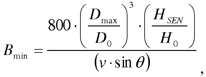
- To solve the above problems, the present invention provides a method for continuously casting steel, the method comprising supplying molten steel into a mold while applying an electromagnetic brake to an outlet flow discharged from an outlet port of an immersion nozzle, wherein magnetic flux density (B) of the electromagnetic brake is within a range of the following (Formula 1):


- Do = a mold thickness (m) of the mold having short sides and the long sides on a horizontal cross-sectional shape, the mold thickness measured as a distance between the long sides facing each other in the mold at ends of the long sides,
- Dmax = a maximum value of a mold thickness (m) of the mold having the short sides and the long sides on the horizontal cross-sectional shape, the maximum value measured as a distance between the long sides facing each other in the mold at a middle of each long side,
- Ho = a distance (m) between a surface of the molten steel and a center of an electromagnetic brake coil in a vertical direction,
- HSEN = a distance (m) between a bottom surface of the immersion nozzle and the center of the electromagnetic brake coil in the vertical direction,
- v = a flow velocity (m/s) of the molten steel discharged from the immersion nozzle, and
- θ = an outlet flow angle (°) of the molten steel obtained as an angle formed with a horizontal line where an upward direction is a positive.
- In the present invention, a rectangular mold that has short sides and long sides on a horizontal cross-sectional shape can be used as the mold.
- In the present invention wherein a rectangular mold is used as the mold, preferably, the flow velocity v of the molten steel is 0.685 m/s to 0.799 m/s. Whereby, an upward flow is gently generated all over, which makes it easy to check generation of a downward flow along a solidification interface.
- In the present invention, preferably, a funnel mold with short sides and long sides on a horizontal cross-section, in which a distance between the long sides facing each other in the mold at a middle of each long side is enlarged than a distance between the long sides at ends of the long sides, is used as the mold.
- In the present invention wherein a funnel mold is used as the mold, preferably, Dmax/D0 is 1.16 to 1.24. Whereby, even if inclusions are carried by a downward flow, it is easy to decrease the frequency with which these inclusions are supplied to a solidification interface.
- In the present invention wherein a funnel mold is used as the mold, preferably, HSEN/H0 is 0.161 to 0.327. Whereby, an upward flow is gently generated all over, which makes it easy to check generation of a downward flow along a solidification interface.
- In the present invention wherein a funnel mold is used as the mold, preferably, the flow velocity v of the molten steel is 0.441 m/s to 1.256 m/s. Whereby, it is easy to stabilize a molten steel flow in the mold, and to check fluctuation on the surface of the molten steel.
- In the present invention, preferably, the outlet flow angle θ of the molten steel is -45° to -5°. Whereby, it is easy to stabilize a molten steel flow in the mold, and to check fluctuation on the surface of the molten steel.
- According to the present invention that employs the structure that magnetic flux density (B) of the electromagnetic brake is within a range of the above described (Formula 1) in the method for continuously casting steel, the method comprising supplying molten steel into a mold while applying an electromagnetic brake to an outlet flow discharged from an outlet port of an immersion nozzle, occurrence of surface defects caused by the electromagnetic brake can be efficiently avoided even if the mold for manufacturing a thin cast steel is used, while the effect of the electromagnetic brake which is to hold down the descending speed of the molten steel and to reduce internal defects in the cast steel is enjoyed.
- That is, according to the present invention, both internal defects in the mold and surface defects can be surely reduced, and the cleanliness of the cast steel can be improved with an extremely easy method of having the electromagnetic brake of proper magnetic flux density in accordance with the above (Formula 1).
-
-
Fig. 1 is a schematically explanatory view of a plane showing an outline of structure in the vicinity of a mold of a continuous-casting apparatus in one embodiment of the present invention. -
Fig. 2 is a schematically explanatory view of a front cross-section showing an outline of structure in the vicinity of the mold of the continuous-casting apparatus in one embodiment of the present invention. -
Fig. 3 is an explanatory front cross-sectional view of a state of a molten steel flow in the mold when an electromagnetic brake is operated. -
Fig. 4 is an explanatory side cross-sectional view of a state of the molten steel flow in the mold when the electromagnetic brake is operated. - A preferred embodiment of the present invention will be described hereinafter.
- In this embodiment, as shown in
Fig. 1 , animmersion nozzle 2 is arranged around the middle from the long and short sides of amold 1 whose horizontal cross-sectional shape is almost rectangular. As shown inFig. 2 , anelectromagnetic brake device 4 is oppositely arranged so that themold 1 is sandwiched therein, outsidelong side walls 3 that compose long sides of themold 1, at a position downward from the lower end of theimmersion nozzle 2. - In this embodiment, as shown in
Fig. 1 , a funnel mold with short sides and long sides on a horizontal cross-section, in which a distance between the long sides facing each other in the mold at a middle of each long side is enlarged than a distance between the long sides at ends of the long sides, is used as the mold. Other than this, in the present invention, a rectangular mold where Dmax = D0 can be used. Here, satisfaction of Dmax > D0 can make a swirl flow around the surface of the molten steel in the horizontal direction stable. In addition, a solidification shell is kept away from a downward flow that is generated by turning-around near the surface of the molten steel, thereby the occasions of catching inclusions and bubbles can be decreased. - An
outlet port 5 from which molten steel is discharged in themold 1 diagonally downward is formed on each portion of theimmersion nozzle 2 which facesshort side walls mold 1 respectively. Bubbles of an Ar gas, and alumina and slag-type inclusions are contained in anoutlet flow 6 discharged from theoutlet port 5 because an Ar gas is blew into theimmersion nozzle 2. - In this embodiment, the
electromagnetic brake device 4 is oppositely arranged so that themold 1 is sandwiched therein, at a position downward from the lower end part of theimmersion nozzle 2 in order to avoid the phenomenon that those bubbles of Ar gas, and alumina and slag-type inclusions infiltrate into a deep portion of the cast steel, to be internal defects while not floating up or removed enough in themold 1. - The
electromagnetic brake device 4 is composed of an electromagnet etc. Theelectromagnetic brake device 4 can apply a DC magnetic field to theoutlet flow 6 just after discharged from theoutlet port 5 of theimmersion nozzle 2, in the mold thickness direction (Y direction inFig. 1 ) along theshort side walls mold 1. This DC magnetic field has almost uniform magnetic flux density distribution in all the mold width direction (X direction inFig. 1 ) along thelong side walls mold 1. An induced current in the X direction inFig. 1 is generated by this DC magnetic field and outlet flow. A counterflow that flows in the opposite direction to theoutlet flow 6 is formed in the vicinity of theoutlet flow 6 by this induced current and the DC magnetic field, to hold down the descendent speed of the molten steel. Whereby, the phenomenon that bubbles and inclusions such as alumina remaining in the molten steel infiltrate into a deep part of the cast steel while not floating up or removed enough can be avoided. - When an electromagnetic brake is operated on an outlet flow in a conventional art, as shown in
Figs. 3 and4 , an upward flow along theimmersion nozzle 2 is generated. This upward flow turns around near the surface of the molten steel, to be a downward flow. Especially, in a mold where Do is about no more than 400 mm, inclusions and bubbles carried by this downward flow are easy to be in contact with a solidifiedshell 8 on thelong side walls shell 8 on thelong side walls - The above (Formula 1) was obtained through inventors' various studies. The effect of the present invention is brought about only with the combination of all the elements composing the above (Formula 1). Here, Bmin is the lower limit of a proper range of the magnetic flux density of the electromagnetic brake. If the magnetic flux density is under this lower limit, it cannot be prevented that inclusions and bubbles are carried by the outlet flow, to infiltrate downward. Bmax is the upper limit of a proper range of the magnetic flux density of the electromagnetic brake. If the magnetic flux density is over this upper limit, the upward flow along the
immersion nozzle 2 becomes too strong, and thus, the downward flow turning around according to this also becomes strong. Therefore, the frequency with which inclusions and bubbles carried by this downward flow are in contact with the solidifiedshell 8 becomes high. As a result, surface defects are easy to occur. Bmin and Bmax are defined by the combination of some factors that influence flows in the mold. - Specifically, both internal defects in the mold and surface defects can be reduced, and the cleanliness of the cast steel can be improved only with the combination of a mold thickness (m) of the mold having short sides and the long sides on a horizontal cross-sectional shape, the mold thickness measured as a distance between the long sides facing each other in the mold at ends of the long sides (D0), a maximum value of a mold thickness (m) of the mold having the short sides and the long sides on the horizontal cross-sectional shape, the maximum value measured as a distance between the long sides facing each other in the mold at a middle of each long side (Dmax), a distance (m) between a surface of the molten steel and a center of an electromagnetic brake coil in a vertical direction (Ho), a distance (m) between a bottom surface of the immersion nozzle and the center of the electromagnetic brake coil in the vertical direction (HSEN), a flow velocity (m/s) of the molten steel discharged from the immersion nozzle (v), and an outlet flow angle (°) of the molten steel (θ), so as to satisfy the above (Formula 1).
- The smaller the value of HSEN is, the stronger breaking force of the electromagnetic brake to the outlet flow is. Thus, the descendent speed of the outlet flow is held down, and the velocity of the upward flow shown in
Figs. 3 and4 becomes high. As a result, the velocity of the downward flow that is formed by the upward flow turning around near the surface of the molten steel also becomes high. Therefore, the probability that inclusions and bubbles carried by this downward flow are in contact with the solidifiedshell 8 on thelong side walls - On the other hand, if the value of HSEN is large so as to approach H0, the effect of the electromagnetic brake weakens, and in addition, fluctuation of the surface of the molten steel becomes large. As a result, involvement of mold powder is easy to occur.
- A larger value of θ necessitates breaking force by the larger electromagnetic brake. The upward flow also tends to be large.
- As described above, increase and decrease of each variable in the above (Formula 1) brings about different effects. Thus, conventionally, it is difficult to determine proper magnetic flux density of the electromagnetic brake in continuous-casting equipment configured by the combination of them whenever the size of a mold, the casting speed, an immersion nozzle, etc. are changed. In contrast, according to the present invention, both internal defects in the mold and surface defects can be surely reduced, and the cleanliness of the cast steel can be improved with an extremely easy method of having the electromagnetic brake of proper magnetic flux density in accordance with the above (Formula 1).
- In the present invention, in a case where the mold is a rectangular mold where Dmax = Do, the flow velocity of the molten steel v discharged from the immersion nozzle is preferably 0.685 m/s to 0.799 m/s. The flow velocity of the molten steel v of no less than 0.685 m/s makes it easy to obtain the molten steel flow for checking inclusions to be caught by a solidification interface. The flow velocity of the molten steel v of no more than 0.799 m/s makes it easy to check fluctuation on the surface of the molten steel.
- On the other hand, in the present invention, in a case where the mold is a funnel mold, Dmax/D0 is preferably 1.16 to 1.24. Dmax/D0 of no less than 1.16 makes it easy to gently form the upward flow all over, and to check generation of the downward flow along the solidification interface. Dmax/D0 of no more than 1.24 makes it easy to reduce the drag when the solidified shell is withdrawn from the mold. In the case where the mold is a funnel mold, Dmax/D0 is more preferably 1.18 to 1.22 in view of making the above effect outstanding.
- In the case where the mold is a funnel mold, preferably, HSEN/H0 is 0.161 to 0.327. HSEN/H0 of no less than 0.161 makes it easy to stabilize heat supply to the surface of the molten steel. HSEN/H0 of no more than 0.327 makes it easy to check fluctuation on the surface of the molten steel. In the case where the mold is a funnel mold, HSEN/H0 is more preferably 0.15 to 0.30 in view of making the above effect outstanding.
- In the case where the mold is a funnel mold, preferably, the flow velocity of the molten steel v discharged from the immersion nozzle is 0.441 m/s to 1.256 m/s. The flow velocity of the molten steel v of no less than 0.441 m/s makes it easy to obtain the molten steel flow checking inclusions to be caught, and to supply heat to the surface of the molten steel. The flow velocity of the molten steel v of no more than 1.256 m/s makes it easy to check fluctuation on the surface of the molten steel. In the case where the mold is a funnel mold, more preferably, the flow velocity of the molten steel v is 0.500 m/s to 1.100 m/s in view of making the above effect outstanding.
- In the case where the mold is a funnel mold, preferably, an outlet flow angle θ of the molten steel is -45° to -5°. The outlet flow angle θ of the molten steel of no less than -45° makes it easy to supply heat to the surface of the molten steel. The outlet flow angle θ of the molten steel of no more than -5° makes it easy to check fluctuation on the surface of the molten steel. In the case where the mold is a funnel mold, more preferably, the outlet flow angle θ of the molten steel is -45° to -15° in view of making the above effect outstanding.
- Continuous casting of steel was carried out under the casting conditions shown in Table 1 below, and the quality of produced coils was evaluated. Specifically, the quality of coils was evaluated as follows: visual inspections were done on coils of no less than 50 in each Example, to count sliver defects; and evaluation was made according to the number of defects like: ⊚ (excellent: the number of defects ≤ 0.5/a coil); ○ (good: 0.5/a coil < the number of defects ≤ 1.0/a coil); and × (poor: the number of defects > 1.0/a coil).
[Table 1] Casting Speed Mold Immersion Nozzle Bmin and Bmax in Formula 1Quality of Coils Shape of Bottom Funnel Portion Electromagnetic Brake Distance between BottomSurface of Nozzle and Center of Coil Outlet Flow Velocity Outlet Flow Angle Electromagnetic Brake Width Thickness Thickness Magnetic Flux Density Distance between Surface and Center of Coil Proper Strength Range Vc W0 D0 Dmax B H0 HSEN v θ Bmin Bmax m/min mm mm mm G mm mm m/s deg. G G Ex. 1 1.4 1630 250 290 4100 606.5 198 0.799 -45 722 4789 ⊚ Ex. 2 1.4 1630 250 310 4100 606.5 198 0.799 -45 881 5850 ⊚ Ex. 3 1.4 1630 250 250 4100 606.5 148 0.799 -30 489 4587 ○ Ex. 4 1.4 1630 250 290 4100 606.5 148 0.799 -30 763 7159 ⊚ Ex. 5 1.4 1630 250 310 4100 606.5 148 0.799 -30 932 8745 ⊚ Ex. 6 1.4 1630 250 300 4100 606.5 198 0.799 -45 799 5302 ⊚ Ex. 7 1.4 1400 250 300 4100 606.5 198 0.686 -45 930 7187 ⊚ Ex. 8 1.4 1150 250 300 4100 606.5 198 0.564 -45 1132 10651 ⊚ Ex. 9 1.4 900 250 300 4100 606.5 198 0.441 -45 1447 17390 ⊚ Ex. 10 1.0 1630 250 300 4100 606.5 148 0.571 -30 1182 15534 ○ Ex. 11 1.4 1630 250 300 4100 606.5 148 0.799 -30 844 7926 ⊚ Ex. 12 1.8 1630 250 300 1100 606.5 148 1.027 -30 657 4795 ○ Ex. 13 1.8 1630 250 300 1800 606.5 148 1.027 -30 657 4795 ⊚ Ex. 14 1.8 1630 250 300 4100 606.5 148 1.027 -30 657 4795 ⊚ Ex. 15 1.8 1630 250 300 4400 606.5 148 1.027 -30 657 4795 ⊚ Ex. 16 1.8 1630 250 300 4600 606.5 148 1.027 -30 657 4795 ○ Ex. 17 1.0 1630 250 300 4100 606.5 198 0.571 -45 1118 10391 ○ Ex. 18 1.4 1630 250 300 4100 606.5 198 0.799 -45 799 5302 ⊚ Ex. 19 1.0 1630 250 300 4100 606.5 198 0.571 -30 1581 20783 ○ Ex. 20 1.4 1630 250 300 4100 606.5 198 0.799 -30 1130 10603 ⊚ Ex. 21 1.8 1630 250 300 4100 606.5 198 1.027 -30 879 6414 ⊚ Ex. 22 2.2 1630 250 300 800 606.5 198 1.256 -30 719 4294 ○ Ex. 23 1.4 1630 250 300 4100 606.5 98 0.799 -30 559 5248 ⊚ Ex. 24 1.4 1630 250 300 4100 606.5 98 0.799 -15 1080 19586 ⊚ Ex. 25 1.4 1630 250 300 4100 606.5 98 0.799 -5 3208 172724 ○ Ex. 26 1.0 1630 300 300 3000 606.5 148 0.685 -30 570 6243 ○ Ex. 27 1.0 1630 300 350 1500 606.5 148 0.685 -30 905 9914 ○ Comp. Ex. 1 1.4 1630 250 250 4100 606.5 198 0.799 -45 462 1303 × Comp. Ex. 2 1.4 1630 250 300 4100 606.5 148 0.799 -45 597 3963 × Comp. Ex. 3 2.2 1630 250 300 4100 606.5 148 1.256 -30 537 3210 × Comp. Ex. 4 1.8 1630 250 300 4100 606.5 198 1.027 -45 621 3207 × Comp. Ex. 5 2.2 1630 250 300 4100 606.5 198 1.256 -45 508 2147 × Comp. Ex. 6 1.4 1630 250 300 4100 606.5 98 0.799 -45 395 2624 × Comp. Ex. 7 1.8 1630 250 300 500 606.5 148 1.027 -30 657 4795 × Comp. Ex. 8 1.8 1630 250 300 5000 606.5 148 1.027 -30 657 4795 × Comp. Ex. 9 1.4 1630 300 300 4500 606.5 148 0.959 -30 407 3185 × Comp. Ex 10 1.4 1630 300 350 500 606.5 148 0.959 -30 647 5058 × - In each Example 1, 2, 4, 5, 6, 7, 8, 9, 11, 13, 14, 15, 18, 20, 21, 23 and 24, the magnetic flux density of the electromagnetic brake was within a proper range, and a funnel mold was used. As shown in these Examples, it was confirmed that the quality of coils in every Example was excellent ⊚ when the magnetic flux density of the electromagnetic brake was within a proper range and a funnel mold was used, without any influence of other casting conditions (the casting speed, the casting width, the thickness of an expanding part of a funnel portion, and the conditions of the immersion nozzle).
- In each Example 3 and 26, the magnetic flux density of the electromagnetic brake was within a proper range but a rectangular mold without a funnel portion was used. The quality of coils under this condition was good ○.
- In each Example 10, 17, 19 and 27, a funnel mold was used, the magnetic flux density of the electromagnetic brake was within a proper range, and the casting speed was low. The quality of coils under this condition was good ○ in every Example.
- In Example 22, a funnel mold was used, the magnetic flux density of the electromagnetic brake was within a proper range, and the casting speed was high. The quality of coils under this condition was good ○.
- In Example 25, a funnel mold was used and the magnetic flux density of the electromagnetic brake was within a proper range with a slight outlet flow angle (-5°). The quality of coils under this condition was good ○.
- In each Comparative Example 1 to 10, the magnetic flux density of the electromagnetic brake was not within a proper range. The quality of coils under this condition was poor × in every Example.
- In each Comparative Example 7 and 8 and Example 12 to 16, conditions other than the magnetic flux density of the electromagnetic brake were standardized, and a proper range of the magnetic flux density of the electromagnetic brake according to the above described (Formula 1) was 657 to 4795 (Gauss).
- In each Example 13 to 15, the magnetic flux density of the electromagnetic brake was within a proper range and remote from both upper and lower limits. It was confirmed that the quality of coils in every Example was excellent ⊚.
- In Comparative Example 7, the magnetic flux density of the electromagnetic brake was lower than the lower limit of a proper range in 24%. In Comparative Example 8, the magnetic flux density of the electromagnetic brake was higher than the upper limit of a proper range in 4%. The quality of coils in every Example was poor ×.
- In Example 12 where a funnel mold was used, the magnetic flux density of the electromagnetic brake was within a proper range and close to the lower limit compared with the density in each Example 13 to 15. The quality of coils under this condition was good ○.
- In Example 16 where a funnel mold was used, the magnetic flux density of the electromagnetic brake was within a proper range and close to the upper limit compared with the density in each Example 13 to 15. The quality of coils under this condition was good ○.
-
- 1 ... mold
- 2 ... immersion nozzle
- 3, 3a, 3b ... long side wall
- 4 ... electromagnetic brake device
- 5 ... outlet port
- 6 ... outlet flow
- 7a, 7b ... short side wall
- 8 ... solidified shell
- 9 ... center of an electromagnetic brake coil
Claims (8)
- A method for continuously casting steel, the method comprising supplying molten steel into a mold while applying an electromagnetic brake to an outlet flow discharged from an outlet port of an immersion nozzle,
wherein magnetic flux density (B) of the electromagnetic brake is within a range of the following (Formula 1):

 Do = a mold thickness (m) of the mold having short sides and long sides on a horizontal cross-sectional shape, the mold thickness measured as a distance between the long sides facing each other in the mold at ends of the long sides,Dmax = a maximum value of a mold thickness (m) of the mold having the short sides and the long sides on the horizontal cross-sectional shape, the maximum value measured as a distance between the long sides facing each other in the mold at a middle of each long side,H0 = a distance (m) between a surface of the molten steel and a center of an electromagnetic brake coil in a vertical direction,HSEN = a distance (m) between a bottom surface of the immersion nozzle and the center of the electromagnetic brake coil in the vertical direction,v = a flow velocity (m/s) of the molten steel discharged from the immersion nozzle, andθ = an outlet flow angle (°) of the molten steel.
 - The method for continuously casting steel according to claim 1, wherein a rectangular mold that has short sides and long sides on a horizontal cross-sectional shape is used as the mold.
- The method for continuously casting steel according to claim 2, wherein the flow velocity v of the molten steel is 0.685 m/s to 0.799 m/s.
- The method for continuously casting steel according to claim 1, wherein
a funnel mold with short sides and long sides on a horizontal cross-section, in which a distance between the long sides facing each other in the mold at a middle of each long side is enlarged than a distance between the long sides at ends of the long sides, is used as the mold. - The method for continuously casting steel according to claim 4, wherein Dmax/D0 is 1.16 to 1.24.
- The method for continuously casting steel according to claim 4 or 5, wherein HSEN/H0 is 0.161 to 0.327.
- The method for continuously casting steel according to any of claims 4 to 6, wherein the flow velocity v of the molten steel is 0.441 m/s to 1.256 m/s.
- The method for continuously casting steel according to any of claims 4 to 7, wherein the outlet flow angle θ of the molten steel is -45° to -5°.
Applications Claiming Priority (2)
| Application Number | Priority Date | Filing Date | Title |
|---|---|---|---|
| JP2015072279 | 2015-03-31 | ||
| PCT/JP2016/060769 WO2016159284A1 (en) | 2015-03-31 | 2016-03-31 | Continuous casting method for steel |
Publications (3)
| Publication Number | Publication Date |
|---|---|
| EP3278906A1 true EP3278906A1 (en) | 2018-02-07 |
| EP3278906A4 EP3278906A4 (en) | 2018-12-05 |
| EP3278906B1 EP3278906B1 (en) | 2020-04-29 |
Family
ID=57004396
Family Applications (1)
| Application Number | Title | Priority Date | Filing Date |
|---|---|---|---|
| EP16773164.5A Not-in-force EP3278906B1 (en) | 2015-03-31 | 2016-03-31 | Continuous casting method for steel |
Country Status (9)
| Country | Link |
|---|---|
| US (2) | US10259037B2 (en) |
| EP (1) | EP3278906B1 (en) |
| JP (1) | JP6428923B2 (en) |
| KR (2) | KR20190016613A (en) |
| CN (1) | CN107107175B (en) |
| BR (1) | BR112017013367A2 (en) |
| CA (1) | CA2971130C (en) |
| TW (1) | TWI590892B (en) |
| WO (1) | WO2016159284A1 (en) |
Families Citing this family (5)
| Publication number | Priority date | Publication date | Assignee | Title |
|---|---|---|---|---|
| EP3278906B1 (en) | 2015-03-31 | 2020-04-29 | Nippon Steel Corporation | Continuous casting method for steel |
| US20200009650A1 (en) * | 2017-03-03 | 2020-01-09 | Nippon Steel Stainless Steel Corporation | Continuous casting method and continuous casting device |
| KR102324300B1 (en) * | 2017-04-25 | 2021-11-09 | 제이에프이 스틸 가부시키가이샤 | Method of continuous casting of steel |
| TW202000340A (en) * | 2018-06-07 | 2020-01-01 | 日商日本製鐵股份有限公司 | Device and method for controlling steel flow in mold for thin slab casting |
| CN112643007B (en) * | 2020-11-23 | 2022-05-20 | 首钢集团有限公司 | Continuous casting method for reducing large-size impurities on surface layer of aluminum-containing steel casting blank |
Family Cites Families (17)
| Publication number | Priority date | Publication date | Assignee | Title |
|---|---|---|---|---|
| JPS5245800A (en) | 1975-10-07 | 1977-04-11 | Hitachi Koki Kk | Fastening tool |
| JPS5659565A (en) * | 1979-10-22 | 1981-05-23 | Nippon Kokan Kk <Nkk> | Mold for continuous casting |
| JPH06142865A (en) * | 1992-11-10 | 1994-05-24 | Nippon Steel Corp | Control method of flow in mold by DC magnetic field |
| JPH06262314A (en) * | 1993-03-16 | 1994-09-20 | Nisshin Steel Co Ltd | Method for controlling fluidity of molten steel in continuous casting mold |
| DE4403050C1 (en) * | 1994-01-28 | 1995-09-28 | Mannesmann Ag | Continuous casting mold for guiding strands |
| JP3316108B2 (en) * | 1994-07-14 | 2002-08-19 | 川崎製鉄株式会社 | Steel continuous casting method |
| JPH0852544A (en) * | 1994-08-10 | 1996-02-27 | Nippon Steel Corp | Method for manufacturing defect-free slab |
| JPH09277001A (en) * | 1996-04-19 | 1997-10-28 | Nippon Steel Corp | Continuous casting method for stainless steel slab |
| CN1196548C (en) * | 2000-03-09 | 2005-04-13 | 杰富意钢铁株式会社 | Manufacturing method of continuous casting slab |
| JP4543562B2 (en) * | 2001-02-20 | 2010-09-15 | Jfeスチール株式会社 | Continuous casting method for molten steel |
| JP4746398B2 (en) * | 2005-10-11 | 2011-08-10 | 新日本製鐵株式会社 | Steel continuous casting method |
| JP4724606B2 (en) * | 2006-06-05 | 2011-07-13 | 新日本製鐵株式会社 | Continuous casting method for molten steel |
| JP2008183597A (en) | 2007-01-31 | 2008-08-14 | Jfe Steel Kk | Steel continuous casting method and steel plate manufacturing method |
| JP5014934B2 (en) * | 2007-09-13 | 2012-08-29 | 新日本製鐵株式会社 | Steel continuous casting method |
| JP5245800B2 (en) | 2008-06-30 | 2013-07-24 | Jfeスチール株式会社 | Continuous casting mold and steel continuous casting method |
| KR20140053279A (en) | 2011-11-09 | 2014-05-07 | 신닛테츠스미킨 카부시키카이샤 | Continuous casting device for steel |
| EP3278906B1 (en) | 2015-03-31 | 2020-04-29 | Nippon Steel Corporation | Continuous casting method for steel |
-
2016
- 2016-03-31 EP EP16773164.5A patent/EP3278906B1/en not_active Not-in-force
- 2016-03-31 CA CA2971130A patent/CA2971130C/en not_active Expired - Fee Related
- 2016-03-31 US US15/535,439 patent/US10259037B2/en not_active Expired - Fee Related
- 2016-03-31 WO PCT/JP2016/060769 patent/WO2016159284A1/en not_active Ceased
- 2016-03-31 TW TW105110318A patent/TWI590892B/en not_active IP Right Cessation
- 2016-03-31 JP JP2017510215A patent/JP6428923B2/en active Active
- 2016-03-31 KR KR1020197003844A patent/KR20190016613A/en not_active Withdrawn
- 2016-03-31 CN CN201680004565.4A patent/CN107107175B/en not_active Expired - Fee Related
- 2016-03-31 BR BR112017013367-9A patent/BR112017013367A2/en not_active Application Discontinuation
- 2016-03-31 KR KR1020177016340A patent/KR20170086574A/en not_active Abandoned
-
2019
- 2019-01-24 US US16/255,904 patent/US10512970B2/en not_active Expired - Fee Related
Also Published As
| Publication number | Publication date |
|---|---|
| BR112017013367A2 (en) | 2018-01-09 |
| JPWO2016159284A1 (en) | 2017-09-14 |
| JP6428923B2 (en) | 2018-11-28 |
| CA2971130C (en) | 2019-08-13 |
| KR20190016613A (en) | 2019-02-18 |
| WO2016159284A1 (en) | 2016-10-06 |
| TWI590892B (en) | 2017-07-11 |
| US20190151937A1 (en) | 2019-05-23 |
| TW201641186A (en) | 2016-12-01 |
| CN107107175A (en) | 2017-08-29 |
| CN107107175B (en) | 2020-03-24 |
| US10259037B2 (en) | 2019-04-16 |
| US20180009026A1 (en) | 2018-01-11 |
| EP3278906B1 (en) | 2020-04-29 |
| US10512970B2 (en) | 2019-12-24 |
| EP3278906A4 (en) | 2018-12-05 |
| CA2971130A1 (en) | 2016-10-06 |
| KR20170086574A (en) | 2017-07-26 |
Similar Documents
| Publication | Publication Date | Title |
|---|---|---|
| US10512970B2 (en) | Method for continuously casting steel | |
| EP2361703B1 (en) | Device for continuously casting steel | |
| EP2754513A1 (en) | Continuous casting device for steel | |
| EP2500120B1 (en) | Method of continuous casting of steel | |
| RU2677560C2 (en) | Mold for continuous casting machine and continuous casting method for steel | |
| EP3332889B1 (en) | Continuous casting method for slab casting piece | |
| EP2842658A1 (en) | Submerged nozzle of continuous casting apparatus | |
| JP5321528B2 (en) | Equipment for continuous casting of steel | |
| CN110035844A (en) | Continuous casting process | |
| EP3597328B1 (en) | Continuous casting method for steel | |
| CN101652206A (en) | Continuous casting device of slab and its continuous casting method | |
| CN101257988B (en) | Method of continuous casting of steel | |
| CN112236249B (en) | Continuous casting equipment and continuous casting method used for casting thin slab of steel | |
| US12275060B2 (en) | Continuous casting method of steel | |
| JPWO2013069121A1 (en) | Steel continuous casting equipment | |
| JP2019177409A (en) | Ingot, method for producing same and method for producing steel plate |
Legal Events
| Date | Code | Title | Description |
|---|---|---|---|
| STAA | Information on the status of an ep patent application or granted ep patent |
Free format text: STATUS: THE INTERNATIONAL PUBLICATION HAS BEEN MADE |
|
| PUAI | Public reference made under article 153(3) epc to a published international application that has entered the european phase |
Free format text: ORIGINAL CODE: 0009012 |
|
| STAA | Information on the status of an ep patent application or granted ep patent |
Free format text: STATUS: REQUEST FOR EXAMINATION WAS MADE |
|
| 17P | Request for examination filed |
Effective date: 20170609 |
|
| AK | Designated contracting states |
Kind code of ref document: A1 Designated state(s): AL AT BE BG CH CY CZ DE DK EE ES FI FR GB GR HR HU IE IS IT LI LT LU LV MC MK MT NL NO PL PT RO RS SE SI SK SM TR |
|
| AX | Request for extension of the european patent |
Extension state: BA ME |
|
| DAV | Request for validation of the european patent (deleted) | ||
| DAX | Request for extension of the european patent (deleted) | ||
| A4 | Supplementary search report drawn up and despatched |
Effective date: 20181106 |
|
| RIC1 | Information provided on ipc code assigned before grant |
Ipc: B22D 11/18 20060101ALI20181029BHEP Ipc: B22D 11/11 20060101AFI20181029BHEP Ipc: B22D 11/115 20060101ALI20181029BHEP Ipc: B22D 11/04 20060101ALI20181029BHEP |
|
| RAP1 | Party data changed (applicant data changed or rights of an application transferred) |
Owner name: NIPPON STEEL CORPORATION |
|
| GRAJ | Information related to disapproval of communication of intention to grant by the applicant or resumption of examination proceedings by the epo deleted |
Free format text: ORIGINAL CODE: EPIDOSDIGR1 |
|
| GRAP | Despatch of communication of intention to grant a patent |
Free format text: ORIGINAL CODE: EPIDOSNIGR1 |
|
| RIC1 | Information provided on ipc code assigned before grant |
Ipc: B22D 11/18 20060101ALI20190918BHEP Ipc: B22D 11/041 20060101ALI20190918BHEP Ipc: B22D 11/11 20060101AFI20190918BHEP Ipc: B22D 11/115 20060101ALI20190918BHEP Ipc: B22D 11/04 20060101ALI20190918BHEP |
|
| GRAJ | Information related to disapproval of communication of intention to grant by the applicant or resumption of examination proceedings by the epo deleted |
Free format text: ORIGINAL CODE: EPIDOSDIGR1 |
|
| GRAP | Despatch of communication of intention to grant a patent |
Free format text: ORIGINAL CODE: EPIDOSNIGR1 |
|
| RIN1 | Information on inventor provided before grant (corrected) |
Inventor name: HANAO, MASAHITO Inventor name: MIYAHARA, MASATOSHI Inventor name: UCHIYAMA, HIROAKI Inventor name: FUJIMOTO, KOHEI |
|
| GRAP | Despatch of communication of intention to grant a patent |
Free format text: ORIGINAL CODE: EPIDOSNIGR1 |
|
| STAA | Information on the status of an ep patent application or granted ep patent |
Free format text: STATUS: GRANT OF PATENT IS INTENDED |
|
| INTG | Intention to grant announced |
Effective date: 20191219 |
|
| GRAS | Grant fee paid |
Free format text: ORIGINAL CODE: EPIDOSNIGR3 |
|
| GRAA | (expected) grant |
Free format text: ORIGINAL CODE: 0009210 |
|
| STAA | Information on the status of an ep patent application or granted ep patent |
Free format text: STATUS: THE PATENT HAS BEEN GRANTED |
|
| AK | Designated contracting states |
Kind code of ref document: B1 Designated state(s): AL AT BE BG CH CY CZ DE DK EE ES FI FR GB GR HR HU IE IS IT LI LT LU LV MC MK MT NL NO PL PT RO RS SE SI SK SM TR |
|
| REG | Reference to a national code |
Ref country code: GB Ref legal event code: FG4D |
|
| REG | Reference to a national code |
Ref country code: CH Ref legal event code: EP |
|
| REG | Reference to a national code |
Ref country code: DE Ref legal event code: R096 Ref document number: 602016035188 Country of ref document: DE |
|
| REG | Reference to a national code |
Ref country code: AT Ref legal event code: REF Ref document number: 1262545 Country of ref document: AT Kind code of ref document: T Effective date: 20200515 |
|
| REG | Reference to a national code |
Ref country code: IE Ref legal event code: FG4D |
|
| REG | Reference to a national code |
Ref country code: NL Ref legal event code: MP Effective date: 20200429 |
|
| REG | Reference to a national code |
Ref country code: LT Ref legal event code: MG4D |
|
| PG25 | Lapsed in a contracting state [announced via postgrant information from national office to epo] |
Ref country code: FI Free format text: LAPSE BECAUSE OF FAILURE TO SUBMIT A TRANSLATION OF THE DESCRIPTION OR TO PAY THE FEE WITHIN THE PRESCRIBED TIME-LIMIT Effective date: 20200429 Ref country code: NO Free format text: LAPSE BECAUSE OF FAILURE TO SUBMIT A TRANSLATION OF THE DESCRIPTION OR TO PAY THE FEE WITHIN THE PRESCRIBED TIME-LIMIT Effective date: 20200729 Ref country code: IS Free format text: LAPSE BECAUSE OF FAILURE TO SUBMIT A TRANSLATION OF THE DESCRIPTION OR TO PAY THE FEE WITHIN THE PRESCRIBED TIME-LIMIT Effective date: 20200829 Ref country code: PT Free format text: LAPSE BECAUSE OF FAILURE TO SUBMIT A TRANSLATION OF THE DESCRIPTION OR TO PAY THE FEE WITHIN THE PRESCRIBED TIME-LIMIT Effective date: 20200831 Ref country code: SE Free format text: LAPSE BECAUSE OF FAILURE TO SUBMIT A TRANSLATION OF THE DESCRIPTION OR TO PAY THE FEE WITHIN THE PRESCRIBED TIME-LIMIT Effective date: 20200429 Ref country code: LT Free format text: LAPSE BECAUSE OF FAILURE TO SUBMIT A TRANSLATION OF THE DESCRIPTION OR TO PAY THE FEE WITHIN THE PRESCRIBED TIME-LIMIT Effective date: 20200429 Ref country code: GR Free format text: LAPSE BECAUSE OF FAILURE TO SUBMIT A TRANSLATION OF THE DESCRIPTION OR TO PAY THE FEE WITHIN THE PRESCRIBED TIME-LIMIT Effective date: 20200730 |
|
| REG | Reference to a national code |
Ref country code: AT Ref legal event code: MK05 Ref document number: 1262545 Country of ref document: AT Kind code of ref document: T Effective date: 20200429 |
|
| PG25 | Lapsed in a contracting state [announced via postgrant information from national office to epo] |
Ref country code: BG Free format text: LAPSE BECAUSE OF FAILURE TO SUBMIT A TRANSLATION OF THE DESCRIPTION OR TO PAY THE FEE WITHIN THE PRESCRIBED TIME-LIMIT Effective date: 20200729 Ref country code: RS Free format text: LAPSE BECAUSE OF FAILURE TO SUBMIT A TRANSLATION OF THE DESCRIPTION OR TO PAY THE FEE WITHIN THE PRESCRIBED TIME-LIMIT Effective date: 20200429 Ref country code: HR Free format text: LAPSE BECAUSE OF FAILURE TO SUBMIT A TRANSLATION OF THE DESCRIPTION OR TO PAY THE FEE WITHIN THE PRESCRIBED TIME-LIMIT Effective date: 20200429 Ref country code: LV Free format text: LAPSE BECAUSE OF FAILURE TO SUBMIT A TRANSLATION OF THE DESCRIPTION OR TO PAY THE FEE WITHIN THE PRESCRIBED TIME-LIMIT Effective date: 20200429 |
|
| PG25 | Lapsed in a contracting state [announced via postgrant information from national office to epo] |
Ref country code: NL Free format text: LAPSE BECAUSE OF FAILURE TO SUBMIT A TRANSLATION OF THE DESCRIPTION OR TO PAY THE FEE WITHIN THE PRESCRIBED TIME-LIMIT Effective date: 20200429 Ref country code: AL Free format text: LAPSE BECAUSE OF FAILURE TO SUBMIT A TRANSLATION OF THE DESCRIPTION OR TO PAY THE FEE WITHIN THE PRESCRIBED TIME-LIMIT Effective date: 20200429 |
|
| PG25 | Lapsed in a contracting state [announced via postgrant information from national office to epo] |
Ref country code: ES Free format text: LAPSE BECAUSE OF FAILURE TO SUBMIT A TRANSLATION OF THE DESCRIPTION OR TO PAY THE FEE WITHIN THE PRESCRIBED TIME-LIMIT Effective date: 20200429 Ref country code: AT Free format text: LAPSE BECAUSE OF FAILURE TO SUBMIT A TRANSLATION OF THE DESCRIPTION OR TO PAY THE FEE WITHIN THE PRESCRIBED TIME-LIMIT Effective date: 20200429 Ref country code: DK Free format text: LAPSE BECAUSE OF FAILURE TO SUBMIT A TRANSLATION OF THE DESCRIPTION OR TO PAY THE FEE WITHIN THE PRESCRIBED TIME-LIMIT Effective date: 20200429 Ref country code: IT Free format text: LAPSE BECAUSE OF FAILURE TO SUBMIT A TRANSLATION OF THE DESCRIPTION OR TO PAY THE FEE WITHIN THE PRESCRIBED TIME-LIMIT Effective date: 20200429 Ref country code: EE Free format text: LAPSE BECAUSE OF FAILURE TO SUBMIT A TRANSLATION OF THE DESCRIPTION OR TO PAY THE FEE WITHIN THE PRESCRIBED TIME-LIMIT Effective date: 20200429 Ref country code: SM Free format text: LAPSE BECAUSE OF FAILURE TO SUBMIT A TRANSLATION OF THE DESCRIPTION OR TO PAY THE FEE WITHIN THE PRESCRIBED TIME-LIMIT Effective date: 20200429 Ref country code: CZ Free format text: LAPSE BECAUSE OF FAILURE TO SUBMIT A TRANSLATION OF THE DESCRIPTION OR TO PAY THE FEE WITHIN THE PRESCRIBED TIME-LIMIT Effective date: 20200429 Ref country code: RO Free format text: LAPSE BECAUSE OF FAILURE TO SUBMIT A TRANSLATION OF THE DESCRIPTION OR TO PAY THE FEE WITHIN THE PRESCRIBED TIME-LIMIT Effective date: 20200429 |
|
| REG | Reference to a national code |
Ref country code: DE Ref legal event code: R097 Ref document number: 602016035188 Country of ref document: DE |
|
| PG25 | Lapsed in a contracting state [announced via postgrant information from national office to epo] |
Ref country code: SK Free format text: LAPSE BECAUSE OF FAILURE TO SUBMIT A TRANSLATION OF THE DESCRIPTION OR TO PAY THE FEE WITHIN THE PRESCRIBED TIME-LIMIT Effective date: 20200429 Ref country code: PL Free format text: LAPSE BECAUSE OF FAILURE TO SUBMIT A TRANSLATION OF THE DESCRIPTION OR TO PAY THE FEE WITHIN THE PRESCRIBED TIME-LIMIT Effective date: 20200429 |
|
| PLBE | No opposition filed within time limit |
Free format text: ORIGINAL CODE: 0009261 |
|
| STAA | Information on the status of an ep patent application or granted ep patent |
Free format text: STATUS: NO OPPOSITION FILED WITHIN TIME LIMIT |
|
| 26N | No opposition filed |
Effective date: 20210201 |
|
| PG25 | Lapsed in a contracting state [announced via postgrant information from national office to epo] |
Ref country code: SI Free format text: LAPSE BECAUSE OF FAILURE TO SUBMIT A TRANSLATION OF THE DESCRIPTION OR TO PAY THE FEE WITHIN THE PRESCRIBED TIME-LIMIT Effective date: 20200429 |
|
| REG | Reference to a national code |
Ref country code: DE Ref legal event code: R119 Ref document number: 602016035188 Country of ref document: DE |
|
| PG25 | Lapsed in a contracting state [announced via postgrant information from national office to epo] |
Ref country code: MC Free format text: LAPSE BECAUSE OF FAILURE TO SUBMIT A TRANSLATION OF THE DESCRIPTION OR TO PAY THE FEE WITHIN THE PRESCRIBED TIME-LIMIT Effective date: 20200429 |
|
| REG | Reference to a national code |
Ref country code: CH Ref legal event code: PL |
|
| GBPC | Gb: european patent ceased through non-payment of renewal fee |
Effective date: 20210331 |
|
| REG | Reference to a national code |
Ref country code: BE Ref legal event code: MM Effective date: 20210331 |
|
| PG25 | Lapsed in a contracting state [announced via postgrant information from national office to epo] |
Ref country code: DE Free format text: LAPSE BECAUSE OF NON-PAYMENT OF DUE FEES Effective date: 20211001 Ref country code: CH Free format text: LAPSE BECAUSE OF NON-PAYMENT OF DUE FEES Effective date: 20210331 Ref country code: LI Free format text: LAPSE BECAUSE OF NON-PAYMENT OF DUE FEES Effective date: 20210331 Ref country code: LU Free format text: LAPSE BECAUSE OF NON-PAYMENT OF DUE FEES Effective date: 20210331 Ref country code: GB Free format text: LAPSE BECAUSE OF NON-PAYMENT OF DUE FEES Effective date: 20210331 Ref country code: FR Free format text: LAPSE BECAUSE OF NON-PAYMENT OF DUE FEES Effective date: 20210331 Ref country code: IE Free format text: LAPSE BECAUSE OF NON-PAYMENT OF DUE FEES Effective date: 20210331 |
|
| PG25 | Lapsed in a contracting state [announced via postgrant information from national office to epo] |
Ref country code: BE Free format text: LAPSE BECAUSE OF NON-PAYMENT OF DUE FEES Effective date: 20210331 |
|
| PG25 | Lapsed in a contracting state [announced via postgrant information from national office to epo] |
Ref country code: CY Free format text: LAPSE BECAUSE OF FAILURE TO SUBMIT A TRANSLATION OF THE DESCRIPTION OR TO PAY THE FEE WITHIN THE PRESCRIBED TIME-LIMIT Effective date: 20200429 |
|
| PG25 | Lapsed in a contracting state [announced via postgrant information from national office to epo] |
Ref country code: HU Free format text: LAPSE BECAUSE OF FAILURE TO SUBMIT A TRANSLATION OF THE DESCRIPTION OR TO PAY THE FEE WITHIN THE PRESCRIBED TIME-LIMIT; INVALID AB INITIO Effective date: 20160331 |
|
| PG25 | Lapsed in a contracting state [announced via postgrant information from national office to epo] |
Ref country code: MK Free format text: LAPSE BECAUSE OF FAILURE TO SUBMIT A TRANSLATION OF THE DESCRIPTION OR TO PAY THE FEE WITHIN THE PRESCRIBED TIME-LIMIT Effective date: 20200429 |
|
| PG25 | Lapsed in a contracting state [announced via postgrant information from national office to epo] |
Ref country code: TR Free format text: LAPSE BECAUSE OF FAILURE TO SUBMIT A TRANSLATION OF THE DESCRIPTION OR TO PAY THE FEE WITHIN THE PRESCRIBED TIME-LIMIT Effective date: 20200429 |
|
| PG25 | Lapsed in a contracting state [announced via postgrant information from national office to epo] |
Ref country code: MT Free format text: LAPSE BECAUSE OF FAILURE TO SUBMIT A TRANSLATION OF THE DESCRIPTION OR TO PAY THE FEE WITHIN THE PRESCRIBED TIME-LIMIT Effective date: 20200429 |