EP3278770A1 - Method for controlling an orthopedic pivot link device - Google Patents
Method for controlling an orthopedic pivot link device Download PDFInfo
- Publication number
- EP3278770A1 EP3278770A1 EP17189382.9A EP17189382A EP3278770A1 EP 3278770 A1 EP3278770 A1 EP 3278770A1 EP 17189382 A EP17189382 A EP 17189382A EP 3278770 A1 EP3278770 A1 EP 3278770A1
- Authority
- EP
- European Patent Office
- Prior art keywords
- energy
- movement
- flexion
- converted
- stored
- Prior art date
- Legal status (The legal status is an assumption and is not a legal conclusion. Google has not performed a legal analysis and makes no representation as to the accuracy of the status listed.)
- Granted
Links
- 238000000034 method Methods 0.000 title claims abstract description 21
- 230000000399 orthopedic effect Effects 0.000 title claims abstract description 18
- 230000033001 locomotion Effects 0.000 claims abstract description 115
- 238000004146 energy storage Methods 0.000 claims abstract description 34
- 238000006243 chemical reaction Methods 0.000 claims abstract description 30
- 210000003141 lower extremity Anatomy 0.000 claims abstract description 7
- 230000000977 initiatory effect Effects 0.000 claims description 11
- 230000008859 change Effects 0.000 claims description 8
- 230000001133 acceleration Effects 0.000 claims description 7
- 238000000926 separation method Methods 0.000 claims 1
- 210000003127 knee Anatomy 0.000 description 30
- 238000013016 damping Methods 0.000 description 18
- 230000005021 gait Effects 0.000 description 15
- 210000002435 tendon Anatomy 0.000 description 15
- 210000000629 knee joint Anatomy 0.000 description 10
- 238000006073 displacement reaction Methods 0.000 description 9
- 239000003990 capacitor Substances 0.000 description 7
- 238000011161 development Methods 0.000 description 7
- 230000018109 developmental process Effects 0.000 description 7
- 230000009467 reduction Effects 0.000 description 7
- 230000005540 biological transmission Effects 0.000 description 6
- 238000005452 bending Methods 0.000 description 5
- 230000006835 compression Effects 0.000 description 5
- 238000007906 compression Methods 0.000 description 5
- 230000001419 dependent effect Effects 0.000 description 5
- 230000009194 climbing Effects 0.000 description 3
- 230000007423 decrease Effects 0.000 description 3
- 238000005381 potential energy Methods 0.000 description 3
- 230000002040 relaxant effect Effects 0.000 description 3
- 235000019577 caloric intake Nutrition 0.000 description 2
- 238000010586 diagram Methods 0.000 description 2
- 239000012530 fluid Substances 0.000 description 2
- 210000002683 foot Anatomy 0.000 description 2
- 210000002414 leg Anatomy 0.000 description 2
- 230000003387 muscular Effects 0.000 description 2
- 210000000689 upper leg Anatomy 0.000 description 2
- 0 C*(C(C)(C)O)N=O Chemical compound C*(C(C)(C)O)N=O 0.000 description 1
- 238000010521 absorption reaction Methods 0.000 description 1
- 230000009471 action Effects 0.000 description 1
- 230000003213 activating effect Effects 0.000 description 1
- 230000004913 activation Effects 0.000 description 1
- 230000006978 adaptation Effects 0.000 description 1
- 210000003423 ankle Anatomy 0.000 description 1
- 230000008901 benefit Effects 0.000 description 1
- DKOQGJHPHLTOJR-WHRDSVKCSA-N cefpirome Chemical compound N([C@@H]1C(N2C(=C(C[N+]=3C=4CCCC=4C=CC=3)CS[C@@H]21)C([O-])=O)=O)C(=O)\C(=N/OC)C1=CSC(N)=N1 DKOQGJHPHLTOJR-WHRDSVKCSA-N 0.000 description 1
- 230000008878 coupling Effects 0.000 description 1
- 238000010168 coupling process Methods 0.000 description 1
- 238000005859 coupling reaction Methods 0.000 description 1
- 230000003247 decreasing effect Effects 0.000 description 1
- 230000006735 deficit Effects 0.000 description 1
- 230000003111 delayed effect Effects 0.000 description 1
- 238000013461 design Methods 0.000 description 1
- 230000000694 effects Effects 0.000 description 1
- 230000008030 elimination Effects 0.000 description 1
- 238000003379 elimination reaction Methods 0.000 description 1
- 210000004744 fore-foot Anatomy 0.000 description 1
- 210000001624 hip Anatomy 0.000 description 1
- 210000004394 hip joint Anatomy 0.000 description 1
- 230000006872 improvement Effects 0.000 description 1
- 238000012423 maintenance Methods 0.000 description 1
- 210000003205 muscle Anatomy 0.000 description 1
- 238000010248 power generation Methods 0.000 description 1
- 230000008569 process Effects 0.000 description 1
- 238000004064 recycling Methods 0.000 description 1
- 230000001172 regenerating effect Effects 0.000 description 1
- 230000004044 response Effects 0.000 description 1
- 238000004904 shortening Methods 0.000 description 1
- 230000008093 supporting effect Effects 0.000 description 1
- 238000013519 translation Methods 0.000 description 1
- 230000001960 triggered effect Effects 0.000 description 1
Images


Classifications
-
- A—HUMAN NECESSITIES
- A61—MEDICAL OR VETERINARY SCIENCE; HYGIENE
- A61F—FILTERS IMPLANTABLE INTO BLOOD VESSELS; PROSTHESES; DEVICES PROVIDING PATENCY TO, OR PREVENTING COLLAPSING OF, TUBULAR STRUCTURES OF THE BODY, e.g. STENTS; ORTHOPAEDIC, NURSING OR CONTRACEPTIVE DEVICES; FOMENTATION; TREATMENT OR PROTECTION OF EYES OR EARS; BANDAGES, DRESSINGS OR ABSORBENT PADS; FIRST-AID KITS
- A61F2/00—Filters implantable into blood vessels; Prostheses, i.e. artificial substitutes or replacements for parts of the body; Appliances for connecting them with the body; Devices providing patency to, or preventing collapsing of, tubular structures of the body, e.g. stents
- A61F2/50—Prostheses not implantable in the body
- A61F2/68—Operating or control means
-
- A—HUMAN NECESSITIES
- A61—MEDICAL OR VETERINARY SCIENCE; HYGIENE
- A61F—FILTERS IMPLANTABLE INTO BLOOD VESSELS; PROSTHESES; DEVICES PROVIDING PATENCY TO, OR PREVENTING COLLAPSING OF, TUBULAR STRUCTURES OF THE BODY, e.g. STENTS; ORTHOPAEDIC, NURSING OR CONTRACEPTIVE DEVICES; FOMENTATION; TREATMENT OR PROTECTION OF EYES OR EARS; BANDAGES, DRESSINGS OR ABSORBENT PADS; FIRST-AID KITS
- A61F2/00—Filters implantable into blood vessels; Prostheses, i.e. artificial substitutes or replacements for parts of the body; Appliances for connecting them with the body; Devices providing patency to, or preventing collapsing of, tubular structures of the body, e.g. stents
- A61F2/50—Prostheses not implantable in the body
- A61F2/60—Artificial legs or feet or parts thereof
- A61F2/605—Hip joints
-
- A—HUMAN NECESSITIES
- A61—MEDICAL OR VETERINARY SCIENCE; HYGIENE
- A61F—FILTERS IMPLANTABLE INTO BLOOD VESSELS; PROSTHESES; DEVICES PROVIDING PATENCY TO, OR PREVENTING COLLAPSING OF, TUBULAR STRUCTURES OF THE BODY, e.g. STENTS; ORTHOPAEDIC, NURSING OR CONTRACEPTIVE DEVICES; FOMENTATION; TREATMENT OR PROTECTION OF EYES OR EARS; BANDAGES, DRESSINGS OR ABSORBENT PADS; FIRST-AID KITS
- A61F2/00—Filters implantable into blood vessels; Prostheses, i.e. artificial substitutes or replacements for parts of the body; Appliances for connecting them with the body; Devices providing patency to, or preventing collapsing of, tubular structures of the body, e.g. stents
- A61F2/50—Prostheses not implantable in the body
- A61F2/60—Artificial legs or feet or parts thereof
- A61F2/64—Knee joints
-
- A—HUMAN NECESSITIES
- A61—MEDICAL OR VETERINARY SCIENCE; HYGIENE
- A61F—FILTERS IMPLANTABLE INTO BLOOD VESSELS; PROSTHESES; DEVICES PROVIDING PATENCY TO, OR PREVENTING COLLAPSING OF, TUBULAR STRUCTURES OF THE BODY, e.g. STENTS; ORTHOPAEDIC, NURSING OR CONTRACEPTIVE DEVICES; FOMENTATION; TREATMENT OR PROTECTION OF EYES OR EARS; BANDAGES, DRESSINGS OR ABSORBENT PADS; FIRST-AID KITS
- A61F2/00—Filters implantable into blood vessels; Prostheses, i.e. artificial substitutes or replacements for parts of the body; Appliances for connecting them with the body; Devices providing patency to, or preventing collapsing of, tubular structures of the body, e.g. stents
- A61F2/50—Prostheses not implantable in the body
- A61F2/60—Artificial legs or feet or parts thereof
- A61F2/66—Feet; Ankle joints
-
- A—HUMAN NECESSITIES
- A61—MEDICAL OR VETERINARY SCIENCE; HYGIENE
- A61F—FILTERS IMPLANTABLE INTO BLOOD VESSELS; PROSTHESES; DEVICES PROVIDING PATENCY TO, OR PREVENTING COLLAPSING OF, TUBULAR STRUCTURES OF THE BODY, e.g. STENTS; ORTHOPAEDIC, NURSING OR CONTRACEPTIVE DEVICES; FOMENTATION; TREATMENT OR PROTECTION OF EYES OR EARS; BANDAGES, DRESSINGS OR ABSORBENT PADS; FIRST-AID KITS
- A61F2/00—Filters implantable into blood vessels; Prostheses, i.e. artificial substitutes or replacements for parts of the body; Appliances for connecting them with the body; Devices providing patency to, or preventing collapsing of, tubular structures of the body, e.g. stents
- A61F2/50—Prostheses not implantable in the body
- A61F2/68—Operating or control means
- A61F2/70—Operating or control means electrical
-
- A—HUMAN NECESSITIES
- A61—MEDICAL OR VETERINARY SCIENCE; HYGIENE
- A61F—FILTERS IMPLANTABLE INTO BLOOD VESSELS; PROSTHESES; DEVICES PROVIDING PATENCY TO, OR PREVENTING COLLAPSING OF, TUBULAR STRUCTURES OF THE BODY, e.g. STENTS; ORTHOPAEDIC, NURSING OR CONTRACEPTIVE DEVICES; FOMENTATION; TREATMENT OR PROTECTION OF EYES OR EARS; BANDAGES, DRESSINGS OR ABSORBENT PADS; FIRST-AID KITS
- A61F5/00—Orthopaedic methods or devices for non-surgical treatment of bones or joints; Nursing devices; Anti-rape devices
- A61F5/01—Orthopaedic devices, e.g. splints, casts or braces
- A61F5/0102—Orthopaedic devices, e.g. splints, casts or braces specially adapted for correcting deformities of the limbs or for supporting them; Ortheses, e.g. with articulations
-
- A—HUMAN NECESSITIES
- A61—MEDICAL OR VETERINARY SCIENCE; HYGIENE
- A61F—FILTERS IMPLANTABLE INTO BLOOD VESSELS; PROSTHESES; DEVICES PROVIDING PATENCY TO, OR PREVENTING COLLAPSING OF, TUBULAR STRUCTURES OF THE BODY, e.g. STENTS; ORTHOPAEDIC, NURSING OR CONTRACEPTIVE DEVICES; FOMENTATION; TREATMENT OR PROTECTION OF EYES OR EARS; BANDAGES, DRESSINGS OR ABSORBENT PADS; FIRST-AID KITS
- A61F2/00—Filters implantable into blood vessels; Prostheses, i.e. artificial substitutes or replacements for parts of the body; Appliances for connecting them with the body; Devices providing patency to, or preventing collapsing of, tubular structures of the body, e.g. stents
- A61F2/50—Prostheses not implantable in the body
- A61F2/68—Operating or control means
- A61F2/74—Operating or control means fluid, i.e. hydraulic or pneumatic
- A61F2/741—Operating or control means fluid, i.e. hydraulic or pneumatic using powered actuators, e.g. stepper motors or solenoids
-
- A—HUMAN NECESSITIES
- A61—MEDICAL OR VETERINARY SCIENCE; HYGIENE
- A61F—FILTERS IMPLANTABLE INTO BLOOD VESSELS; PROSTHESES; DEVICES PROVIDING PATENCY TO, OR PREVENTING COLLAPSING OF, TUBULAR STRUCTURES OF THE BODY, e.g. STENTS; ORTHOPAEDIC, NURSING OR CONTRACEPTIVE DEVICES; FOMENTATION; TREATMENT OR PROTECTION OF EYES OR EARS; BANDAGES, DRESSINGS OR ABSORBENT PADS; FIRST-AID KITS
- A61F2/00—Filters implantable into blood vessels; Prostheses, i.e. artificial substitutes or replacements for parts of the body; Appliances for connecting them with the body; Devices providing patency to, or preventing collapsing of, tubular structures of the body, e.g. stents
- A61F2/50—Prostheses not implantable in the body
- A61F2/68—Operating or control means
- A61F2/74—Operating or control means fluid, i.e. hydraulic or pneumatic
- A61F2/748—Valve systems
-
- A—HUMAN NECESSITIES
- A61—MEDICAL OR VETERINARY SCIENCE; HYGIENE
- A61F—FILTERS IMPLANTABLE INTO BLOOD VESSELS; PROSTHESES; DEVICES PROVIDING PATENCY TO, OR PREVENTING COLLAPSING OF, TUBULAR STRUCTURES OF THE BODY, e.g. STENTS; ORTHOPAEDIC, NURSING OR CONTRACEPTIVE DEVICES; FOMENTATION; TREATMENT OR PROTECTION OF EYES OR EARS; BANDAGES, DRESSINGS OR ABSORBENT PADS; FIRST-AID KITS
- A61F2/00—Filters implantable into blood vessels; Prostheses, i.e. artificial substitutes or replacements for parts of the body; Appliances for connecting them with the body; Devices providing patency to, or preventing collapsing of, tubular structures of the body, e.g. stents
- A61F2/50—Prostheses not implantable in the body
- A61F2002/5003—Prostheses not implantable in the body having damping means, e.g. shock absorbers
- A61F2002/5006—Dampers, e.g. hydraulic damper
-
- A—HUMAN NECESSITIES
- A61—MEDICAL OR VETERINARY SCIENCE; HYGIENE
- A61F—FILTERS IMPLANTABLE INTO BLOOD VESSELS; PROSTHESES; DEVICES PROVIDING PATENCY TO, OR PREVENTING COLLAPSING OF, TUBULAR STRUCTURES OF THE BODY, e.g. STENTS; ORTHOPAEDIC, NURSING OR CONTRACEPTIVE DEVICES; FOMENTATION; TREATMENT OR PROTECTION OF EYES OR EARS; BANDAGES, DRESSINGS OR ABSORBENT PADS; FIRST-AID KITS
- A61F2/00—Filters implantable into blood vessels; Prostheses, i.e. artificial substitutes or replacements for parts of the body; Appliances for connecting them with the body; Devices providing patency to, or preventing collapsing of, tubular structures of the body, e.g. stents
- A61F2/50—Prostheses not implantable in the body
- A61F2002/5016—Prostheses not implantable in the body adjustable
- A61F2002/503—Prostheses not implantable in the body adjustable for adjusting elasticity, flexibility, spring rate or mechanical tension
-
- A—HUMAN NECESSITIES
- A61—MEDICAL OR VETERINARY SCIENCE; HYGIENE
- A61F—FILTERS IMPLANTABLE INTO BLOOD VESSELS; PROSTHESES; DEVICES PROVIDING PATENCY TO, OR PREVENTING COLLAPSING OF, TUBULAR STRUCTURES OF THE BODY, e.g. STENTS; ORTHOPAEDIC, NURSING OR CONTRACEPTIVE DEVICES; FOMENTATION; TREATMENT OR PROTECTION OF EYES OR EARS; BANDAGES, DRESSINGS OR ABSORBENT PADS; FIRST-AID KITS
- A61F2/00—Filters implantable into blood vessels; Prostheses, i.e. artificial substitutes or replacements for parts of the body; Appliances for connecting them with the body; Devices providing patency to, or preventing collapsing of, tubular structures of the body, e.g. stents
- A61F2/50—Prostheses not implantable in the body
- A61F2002/5016—Prostheses not implantable in the body adjustable
- A61F2002/5032—Prostheses not implantable in the body adjustable for adjusting fluid pressure
-
- A—HUMAN NECESSITIES
- A61—MEDICAL OR VETERINARY SCIENCE; HYGIENE
- A61F—FILTERS IMPLANTABLE INTO BLOOD VESSELS; PROSTHESES; DEVICES PROVIDING PATENCY TO, OR PREVENTING COLLAPSING OF, TUBULAR STRUCTURES OF THE BODY, e.g. STENTS; ORTHOPAEDIC, NURSING OR CONTRACEPTIVE DEVICES; FOMENTATION; TREATMENT OR PROTECTION OF EYES OR EARS; BANDAGES, DRESSINGS OR ABSORBENT PADS; FIRST-AID KITS
- A61F2/00—Filters implantable into blood vessels; Prostheses, i.e. artificial substitutes or replacements for parts of the body; Appliances for connecting them with the body; Devices providing patency to, or preventing collapsing of, tubular structures of the body, e.g. stents
- A61F2/50—Prostheses not implantable in the body
- A61F2002/5016—Prostheses not implantable in the body adjustable
- A61F2002/5033—Prostheses not implantable in the body adjustable for adjusting damping
-
- A—HUMAN NECESSITIES
- A61—MEDICAL OR VETERINARY SCIENCE; HYGIENE
- A61F—FILTERS IMPLANTABLE INTO BLOOD VESSELS; PROSTHESES; DEVICES PROVIDING PATENCY TO, OR PREVENTING COLLAPSING OF, TUBULAR STRUCTURES OF THE BODY, e.g. STENTS; ORTHOPAEDIC, NURSING OR CONTRACEPTIVE DEVICES; FOMENTATION; TREATMENT OR PROTECTION OF EYES OR EARS; BANDAGES, DRESSINGS OR ABSORBENT PADS; FIRST-AID KITS
- A61F2/00—Filters implantable into blood vessels; Prostheses, i.e. artificial substitutes or replacements for parts of the body; Appliances for connecting them with the body; Devices providing patency to, or preventing collapsing of, tubular structures of the body, e.g. stents
- A61F2/50—Prostheses not implantable in the body
- A61F2002/5016—Prostheses not implantable in the body adjustable
- A61F2002/5035—Prostheses not implantable in the body adjustable for adjusting volume flow
-
- A—HUMAN NECESSITIES
- A61—MEDICAL OR VETERINARY SCIENCE; HYGIENE
- A61F—FILTERS IMPLANTABLE INTO BLOOD VESSELS; PROSTHESES; DEVICES PROVIDING PATENCY TO, OR PREVENTING COLLAPSING OF, TUBULAR STRUCTURES OF THE BODY, e.g. STENTS; ORTHOPAEDIC, NURSING OR CONTRACEPTIVE DEVICES; FOMENTATION; TREATMENT OR PROTECTION OF EYES OR EARS; BANDAGES, DRESSINGS OR ABSORBENT PADS; FIRST-AID KITS
- A61F2/00—Filters implantable into blood vessels; Prostheses, i.e. artificial substitutes or replacements for parts of the body; Appliances for connecting them with the body; Devices providing patency to, or preventing collapsing of, tubular structures of the body, e.g. stents
- A61F2/50—Prostheses not implantable in the body
- A61F2002/5038—Hinged joint, e.g. with transverse axle restricting the movement
- A61F2002/5043—Hinged joint, e.g. with transverse axle restricting the movement with rotation-limiting stops, e.g. projections or recesses
-
- A—HUMAN NECESSITIES
- A61—MEDICAL OR VETERINARY SCIENCE; HYGIENE
- A61F—FILTERS IMPLANTABLE INTO BLOOD VESSELS; PROSTHESES; DEVICES PROVIDING PATENCY TO, OR PREVENTING COLLAPSING OF, TUBULAR STRUCTURES OF THE BODY, e.g. STENTS; ORTHOPAEDIC, NURSING OR CONTRACEPTIVE DEVICES; FOMENTATION; TREATMENT OR PROTECTION OF EYES OR EARS; BANDAGES, DRESSINGS OR ABSORBENT PADS; FIRST-AID KITS
- A61F2/00—Filters implantable into blood vessels; Prostheses, i.e. artificial substitutes or replacements for parts of the body; Appliances for connecting them with the body; Devices providing patency to, or preventing collapsing of, tubular structures of the body, e.g. stents
- A61F2/50—Prostheses not implantable in the body
- A61F2002/5072—Prostheses not implantable in the body having spring elements
-
- A—HUMAN NECESSITIES
- A61—MEDICAL OR VETERINARY SCIENCE; HYGIENE
- A61F—FILTERS IMPLANTABLE INTO BLOOD VESSELS; PROSTHESES; DEVICES PROVIDING PATENCY TO, OR PREVENTING COLLAPSING OF, TUBULAR STRUCTURES OF THE BODY, e.g. STENTS; ORTHOPAEDIC, NURSING OR CONTRACEPTIVE DEVICES; FOMENTATION; TREATMENT OR PROTECTION OF EYES OR EARS; BANDAGES, DRESSINGS OR ABSORBENT PADS; FIRST-AID KITS
- A61F2/00—Filters implantable into blood vessels; Prostheses, i.e. artificial substitutes or replacements for parts of the body; Appliances for connecting them with the body; Devices providing patency to, or preventing collapsing of, tubular structures of the body, e.g. stents
- A61F2/50—Prostheses not implantable in the body
- A61F2/68—Operating or control means
- A61F2002/6818—Operating or control means for braking
-
- A—HUMAN NECESSITIES
- A61—MEDICAL OR VETERINARY SCIENCE; HYGIENE
- A61F—FILTERS IMPLANTABLE INTO BLOOD VESSELS; PROSTHESES; DEVICES PROVIDING PATENCY TO, OR PREVENTING COLLAPSING OF, TUBULAR STRUCTURES OF THE BODY, e.g. STENTS; ORTHOPAEDIC, NURSING OR CONTRACEPTIVE DEVICES; FOMENTATION; TREATMENT OR PROTECTION OF EYES OR EARS; BANDAGES, DRESSINGS OR ABSORBENT PADS; FIRST-AID KITS
- A61F2/00—Filters implantable into blood vessels; Prostheses, i.e. artificial substitutes or replacements for parts of the body; Appliances for connecting them with the body; Devices providing patency to, or preventing collapsing of, tubular structures of the body, e.g. stents
- A61F2/50—Prostheses not implantable in the body
- A61F2/68—Operating or control means
- A61F2002/6845—Clutches
-
- A—HUMAN NECESSITIES
- A61—MEDICAL OR VETERINARY SCIENCE; HYGIENE
- A61F—FILTERS IMPLANTABLE INTO BLOOD VESSELS; PROSTHESES; DEVICES PROVIDING PATENCY TO, OR PREVENTING COLLAPSING OF, TUBULAR STRUCTURES OF THE BODY, e.g. STENTS; ORTHOPAEDIC, NURSING OR CONTRACEPTIVE DEVICES; FOMENTATION; TREATMENT OR PROTECTION OF EYES OR EARS; BANDAGES, DRESSINGS OR ABSORBENT PADS; FIRST-AID KITS
- A61F2/00—Filters implantable into blood vessels; Prostheses, i.e. artificial substitutes or replacements for parts of the body; Appliances for connecting them with the body; Devices providing patency to, or preventing collapsing of, tubular structures of the body, e.g. stents
- A61F2/50—Prostheses not implantable in the body
- A61F2/68—Operating or control means
- A61F2002/6854—Operating or control means for locking or unlocking a joint
-
- A—HUMAN NECESSITIES
- A61—MEDICAL OR VETERINARY SCIENCE; HYGIENE
- A61F—FILTERS IMPLANTABLE INTO BLOOD VESSELS; PROSTHESES; DEVICES PROVIDING PATENCY TO, OR PREVENTING COLLAPSING OF, TUBULAR STRUCTURES OF THE BODY, e.g. STENTS; ORTHOPAEDIC, NURSING OR CONTRACEPTIVE DEVICES; FOMENTATION; TREATMENT OR PROTECTION OF EYES OR EARS; BANDAGES, DRESSINGS OR ABSORBENT PADS; FIRST-AID KITS
- A61F2/00—Filters implantable into blood vessels; Prostheses, i.e. artificial substitutes or replacements for parts of the body; Appliances for connecting them with the body; Devices providing patency to, or preventing collapsing of, tubular structures of the body, e.g. stents
- A61F2/50—Prostheses not implantable in the body
- A61F2/68—Operating or control means
- A61F2/70—Operating or control means electrical
- A61F2002/701—Operating or control means electrical operated by electrically controlled means, e.g. solenoids or torque motors
-
- A—HUMAN NECESSITIES
- A61—MEDICAL OR VETERINARY SCIENCE; HYGIENE
- A61F—FILTERS IMPLANTABLE INTO BLOOD VESSELS; PROSTHESES; DEVICES PROVIDING PATENCY TO, OR PREVENTING COLLAPSING OF, TUBULAR STRUCTURES OF THE BODY, e.g. STENTS; ORTHOPAEDIC, NURSING OR CONTRACEPTIVE DEVICES; FOMENTATION; TREATMENT OR PROTECTION OF EYES OR EARS; BANDAGES, DRESSINGS OR ABSORBENT PADS; FIRST-AID KITS
- A61F2/00—Filters implantable into blood vessels; Prostheses, i.e. artificial substitutes or replacements for parts of the body; Appliances for connecting them with the body; Devices providing patency to, or preventing collapsing of, tubular structures of the body, e.g. stents
- A61F2/50—Prostheses not implantable in the body
- A61F2/68—Operating or control means
- A61F2/70—Operating or control means electrical
- A61F2002/704—Operating or control means electrical computer-controlled, e.g. robotic control
-
- A—HUMAN NECESSITIES
- A61—MEDICAL OR VETERINARY SCIENCE; HYGIENE
- A61F—FILTERS IMPLANTABLE INTO BLOOD VESSELS; PROSTHESES; DEVICES PROVIDING PATENCY TO, OR PREVENTING COLLAPSING OF, TUBULAR STRUCTURES OF THE BODY, e.g. STENTS; ORTHOPAEDIC, NURSING OR CONTRACEPTIVE DEVICES; FOMENTATION; TREATMENT OR PROTECTION OF EYES OR EARS; BANDAGES, DRESSINGS OR ABSORBENT PADS; FIRST-AID KITS
- A61F2/00—Filters implantable into blood vessels; Prostheses, i.e. artificial substitutes or replacements for parts of the body; Appliances for connecting them with the body; Devices providing patency to, or preventing collapsing of, tubular structures of the body, e.g. stents
- A61F2/50—Prostheses not implantable in the body
- A61F2/68—Operating or control means
- A61F2/70—Operating or control means electrical
- A61F2002/708—Operating or control means electrical electrically self charging
-
- A—HUMAN NECESSITIES
- A61—MEDICAL OR VETERINARY SCIENCE; HYGIENE
- A61F—FILTERS IMPLANTABLE INTO BLOOD VESSELS; PROSTHESES; DEVICES PROVIDING PATENCY TO, OR PREVENTING COLLAPSING OF, TUBULAR STRUCTURES OF THE BODY, e.g. STENTS; ORTHOPAEDIC, NURSING OR CONTRACEPTIVE DEVICES; FOMENTATION; TREATMENT OR PROTECTION OF EYES OR EARS; BANDAGES, DRESSINGS OR ABSORBENT PADS; FIRST-AID KITS
- A61F2/00—Filters implantable into blood vessels; Prostheses, i.e. artificial substitutes or replacements for parts of the body; Appliances for connecting them with the body; Devices providing patency to, or preventing collapsing of, tubular structures of the body, e.g. stents
- A61F2/50—Prostheses not implantable in the body
- A61F2/76—Means for assembling, fitting or testing prostheses, e.g. for measuring or balancing, e.g. alignment means
- A61F2002/7615—Measuring means
- A61F2002/7625—Measuring means for measuring angular position
-
- A—HUMAN NECESSITIES
- A61—MEDICAL OR VETERINARY SCIENCE; HYGIENE
- A61F—FILTERS IMPLANTABLE INTO BLOOD VESSELS; PROSTHESES; DEVICES PROVIDING PATENCY TO, OR PREVENTING COLLAPSING OF, TUBULAR STRUCTURES OF THE BODY, e.g. STENTS; ORTHOPAEDIC, NURSING OR CONTRACEPTIVE DEVICES; FOMENTATION; TREATMENT OR PROTECTION OF EYES OR EARS; BANDAGES, DRESSINGS OR ABSORBENT PADS; FIRST-AID KITS
- A61F2/00—Filters implantable into blood vessels; Prostheses, i.e. artificial substitutes or replacements for parts of the body; Appliances for connecting them with the body; Devices providing patency to, or preventing collapsing of, tubular structures of the body, e.g. stents
- A61F2/50—Prostheses not implantable in the body
- A61F2/76—Means for assembling, fitting or testing prostheses, e.g. for measuring or balancing, e.g. alignment means
- A61F2002/7615—Measuring means
- A61F2002/764—Measuring means for measuring acceleration
-
- A—HUMAN NECESSITIES
- A61—MEDICAL OR VETERINARY SCIENCE; HYGIENE
- A61F—FILTERS IMPLANTABLE INTO BLOOD VESSELS; PROSTHESES; DEVICES PROVIDING PATENCY TO, OR PREVENTING COLLAPSING OF, TUBULAR STRUCTURES OF THE BODY, e.g. STENTS; ORTHOPAEDIC, NURSING OR CONTRACEPTIVE DEVICES; FOMENTATION; TREATMENT OR PROTECTION OF EYES OR EARS; BANDAGES, DRESSINGS OR ABSORBENT PADS; FIRST-AID KITS
- A61F2/00—Filters implantable into blood vessels; Prostheses, i.e. artificial substitutes or replacements for parts of the body; Appliances for connecting them with the body; Devices providing patency to, or preventing collapsing of, tubular structures of the body, e.g. stents
- A61F2/50—Prostheses not implantable in the body
- A61F2/76—Means for assembling, fitting or testing prostheses, e.g. for measuring or balancing, e.g. alignment means
- A61F2002/7615—Measuring means
- A61F2002/7645—Measuring means for measuring torque, e.g. hinge or turning moment, moment of force
-
- A—HUMAN NECESSITIES
- A61—MEDICAL OR VETERINARY SCIENCE; HYGIENE
- A61F—FILTERS IMPLANTABLE INTO BLOOD VESSELS; PROSTHESES; DEVICES PROVIDING PATENCY TO, OR PREVENTING COLLAPSING OF, TUBULAR STRUCTURES OF THE BODY, e.g. STENTS; ORTHOPAEDIC, NURSING OR CONTRACEPTIVE DEVICES; FOMENTATION; TREATMENT OR PROTECTION OF EYES OR EARS; BANDAGES, DRESSINGS OR ABSORBENT PADS; FIRST-AID KITS
- A61F5/00—Orthopaedic methods or devices for non-surgical treatment of bones or joints; Nursing devices; Anti-rape devices
- A61F5/01—Orthopaedic devices, e.g. splints, casts or braces
- A61F2005/0197—Orthopaedic devices, e.g. splints, casts or braces with spring means
Definitions
- the WO 2007/025116 A2 describes a prosthetic device with an electronically controlled prosthetic knee with a regenerative braking device.
- the kinetic energy present while walking is converted into electrical energy and stored.
- it is intended that the walking behavior is supported or completely controlled.
- An electronic control system is provided to control the operation of the prosthetic device and distribute generated electrical energy.
- Excess electrical energy may be stored in an accumulator or capacitor and retrieved at a convenient time for motion assistance.
- the energy storage devices are large and heavy in the prostheses or orthotics to have sufficient capacity for effective movement support.
- the EP 439 028 B1 describes a pivotal connection between two parts of an orthopedic technical aid in the form of a polycentric prosthetic knee joint, in which under the action of an external force, a hinge member is formed variable in length.
- the change in length of the joint member may be resilient, so that immediately after reduction or elimination of the external force, the joint member resumes its original length.
- the method according to the invention for controlling an orthopedic device of a lower extremity in which the articulation device has an upper part and an articulated lower part and between the upper part and the lower part an energy conversion device is arranged, via which kinetic energy from the relative movement between the lower part during walking and the upper part is converted and / or stored and returned to the joint to support the relative movement, provides that kinetic energy is converted and / or stored within a cycle of motion and within the same cycle of movement of the joint device is fed back as kinetic energy.
- a typical movement cycle of a lower limb orthopedic articulation device that is to say in a typical step cycle, there are phases in which excess energy has to be converted, but also phases in which support with kinetic energy makes sense.
- the device can be designed as a hydraulic damper and / or pneumatic damper, also a configuration may be provided as a generator. Also possible combinations of the above-described facilities with each other.
- the means for converting and / or storing kinetic energy may be provided besides conventional damper means.
- the remaining damping components, typically pneumatic or hydraulic dampers, are still maintained, but in addition either an energy store or a generator, which is reversibly operable as a motor, is provided to remove kinetic energy from the system at the appropriate locations within the movement or to the system. Due to the fact that the hydraulic or pneumatic damping system dissipates a large proportion of the energy, the system for supporting the movement can be kept small and light.
- the time of energy conversion and recycling is determined by a controller.
- a development of the invention provides that kinetic energy is converted and / or stored during an extension movement.
- the reintroduction of kinetic energy may be at the initiation of the swing phase to assist in the swing phase flexion.
- kinetic energy may be re-introduced during the flexion rate maintaining step, and it is contemplated that after reaching the maximum flexion angle, which may be determined by, for example, a reversal of motion or a rate sensor
- the kinetic energy can be supplied again to support the extension movement.
- a supply of kinetic energy can take place at several or all phases or points in time of the step movement described.
- the extension movement is decelerated before reaching the maximum extension, in order to reduce the momentum which occurs in the extension stop during an unrestrained impact.
- This kinetic energy can be converted and / or stored and fed back to initiate and / or assist the flexion of the hinge device.
- kinetic energy can be added to increase or maintain the rate of extension to facilitate and assist sub-parting.
- the kinetic energy can be converted into electrical energy and stored temporarily or converted into potential energy and temporarily stored, for example by charging an energy store, for example a spring or a hydraulic or pneumatic pressure accumulator.
- an energy store for example a spring or a hydraulic or pneumatic pressure accumulator.
- the stored energy is returned to the system in a controlled manner and converted into mechanical work and support of displacement from top to bottom, to support the movement over a longer period of time, so that a movement of the prosthetic or natural movement approximated orthotic device can be done.
- An adaptation to changing gait patterns, the speeds or different patients is according to the prior art only extremely expensive to perform by specially adapted springs are used, which is impractical for daily use.
- the energy output is controlled in the system, so that over a relatively long period of time, the amount of energy required can be fed to affect the gait as desired.
- the supply of mechanical work can be changed by the fact that the energy storage externally supplied or withdrawn energy.
- the energy store is a spring
- the supply of energy can take place in that the spring is re-tensioned, the removal or reduction of the amount of energy can be effected by relaxing the spring, for example by displacing a spring abutment.
- the energy store is embodied as an electrical energy store, for example a capacitor, battery or accumulator
- the change in the amount of energy can be effected by activation of a generator or initiation from a second energy store, reducing the amount of energy by connecting a consumer or diverting it into a second store for electrical energy ,
- a development of the invention provides that the energy store is associated with an actuator, via which the energy storage is filled or brought to a minimum level, if the relative movement is not sufficient. If the energy available by the movement is insufficient to supply the energy store with sufficient energy for the next step or the sequence of movements, the minimum quantity depending on the walking speed, the walking situation and the individual circumstances of a patient, it is provided according to the invention is supplemented during walking and before the return of energy to support the relative movement of the energy storage to a predetermined level, for example by tensioning a spring or by driving a generator that charges the electrical energy storage.
- the energy may be supplied as mechanical work as a function of at least one of the following criteria or a combination of several of the following criteria, namely the angular position of the upper to the lower part, the position of the upper part and / or the lower part in space, an angular velocity of the upper part and / or the lower part, the relative speed between the upper part and lower part, the loading situation and / or the acceleration of the upper part and / or the lower part.
- the positions of the tops and bottoms to each other and in space can be determined by angle sensors or inertial sensors, the speeds to each other or within the space by acceleration sensors or a combination of angle sensor and acceleration sensor.
- the sensors can be used not only to determine the time of the energy release, but also the respective gait situation, the walking speed and the current position of the respective components relative to each other or in space, thereby enabling the amount and course of the energy supply to support the energy supply To determine and control movement.
- a spring is tensioned via an engine as an actuator, it can be designed to be small and coupled with a transmission with the spring so that the spring can be tensioned over a comparatively large period of time. The same applies to the conversion and storage of electrical energy.
- a development of the invention provides that the relative movement is influenced in addition to the influence of the energy storage device via a damper device, so that the control does not have to be exclusively via the energy store, which leads to a great possibility of variation in influencing the gait pattern.
- load peaks can be more easily absorbed via an additional damper device.
- a generator for generating electrical energy and a motor for driving the lower part wherein the generator is preceded by a speed-dependent coupling which connects the generator with a drive means.
- a hydraulic damper unit for damping the pivoting movement between the lower part and the upper part may be arranged, wherein the hydraulic fluid of the hydraulic damper unit serves as an actuator for separating the clutch.
- the clutch may be formed as a speed-dependent slip clutch.
- a flywheel or a pressure accumulator may be provided as a storage device for the kinetic energy.
- the joint device is preferably designed as a hip joint, knee joint or ankle of a prosthesis or orthosis.
- the energy storage device can also be designed as a spring or accumulator, wherein a rechargeable battery is also understood to mean a capacitor or a rechargeable battery.
- the energy store is associated with an actuator which supplies or withdraws energy during the support of the relative movement of the energy store in a controlled manner.
- the controlled supply or the controlled withdrawal of energy from the energy store via an actuator allows a particularly simple and reliable influencing of the gait pattern in semi-active joint devices, in particular in the case of semi-active prosthetic knee joints.
- the conversion device may be designed as a spring or generator to the mechanical work, in a relative movement accumulates between the upper part and the lower part, either in position energy in a spring or electrical energy in an electrical storage device, for example in the form of a rechargeable battery, to store in a rechargeable battery or in a capacitor.
- a separate damper device may be arranged between the upper part and the lower part in order to be able to better control the relative movement when supported by the energy store. By superimposing the influence of the energy store with the separate damper device, a more precise and reliable influencing of the gait pattern can take place.
- the damper device may be designed to be adjustable in order to provide adapted damping as a function of sensor data, for example with regard to the joint angle, the gear speed, an angular speed or an absolute angle of a top part and / or a top part.
- the damper device can be adjusted via an actuator in order to achieve a reduction or increase in the damping.
- the conversion means may be adjustably coupled to the top and / or the bottom to displace an engagement position or an adjustment path. This makes it possible to influence both the amount of energy and the time of energy supply as desired.
- FIG. 1 is a schematic representation of the course of the knee angle ⁇ over time shown.
- the illustration includes a gait cycle, starting from putting on the heel until putting on the heel of the same leg again.
- the knee joint After the initial heel strike with an extended knee joint, ie at a knee angle ⁇ of 180 °, the knee joint initially bends slightly in the stance phase, which is referred to as stance phase flexion.
- stance phase flexion As soon as the foot touches the ground completely, the knee joint is stretched so that a knee angle ⁇ of 180 ° is established.
- the knee angle ⁇ decreases.
- the vertical, dashed line indicates the end of the stance phase and thus the time at which the toe leaves the ground.
- FIG. 2 is a schematic representation of the knee angle ⁇ superimposed with the knee angular velocity v.
- the knee angle course corresponds to that in the FIG. 1 described.
- the knee angular velocity v increases momentarily.
- the stretched phase ie at a knee angle ⁇ of 180 °, the knee angle does not change, likewise the knee angular velocity v remains constant at 0 ° per second.
- the bending of the knee joint towards the end of the stance phase results in an increase in the knee angle velocity v up to a maximum at the toe off
- the further backswing movement of the lower part takes place at a slowing speed until, at a minimum knee angle ⁇ , a reversal of movement begins and the lower part performs an extension movement.
- the knee angular velocity is below the zero line until the time that an extension damping begins, so as not to allow the base to pivot unrestrained in the stretch stop.
- the knee angular velocity v decreases until the lower part has reached the stretch stop and the knee angle ⁇ is again 180 °.
- the knee angular velocity v is then 0.
- the knee angle ⁇ is shown over time during a gait cycle.
- areas are marked in which kinetic energy can be converted or stored from the relative movement between the lower part and the upper part, these areas are provided with the reference symbol o.
- regions are marked with the reference symbol i, in which it may be advantageous to re-supply stored energy to the system in order to support extension or flexion.
- kinetic energy can be absorbed to re-supply it, for example, in the immediately following extension phase.
- the controlled time-delayed supply of the converted or stored energy takes place within the same cycle of movement during predetermined phases i, wherein preferably braking phases are used to convert and / or store energy and acceleration phases to supply this energy again in a time-delayed manner.
- the control is preferably electronic, but in principle, a mechanical control is possible.
- the extension movement after the initial heel contact, the support of the inflection to initiate the swing phase, the maintenance of the flexion speed after the toe off and the support of the flexion movement after reaching the maximum flexion angle are provided as supply phases i.
- a controllable valve 58 is arranged, via which the flow rate from the upper chamber 56 into the lower chamber 55 can be controlled.
- a sawtooth-like beveled positive-locking element 531 is arranged, which is in engagement with a pivotally mounted rack 59, which also has a sawtooth-shaped toothing, which is formed corresponding to that of the positive-locking element 531.
- the valve 58 is opened so far that the valve 58 allows a faster piston movement than the joint device.
- the piston rod 53 is pressed down.
- the valve 58 is controlled mechanically or electrically mechanically or electrically in response to a determined joint angle position or in dependence on a joint angular velocity mechanically or electrically.
- the valve 58 is opened, the spring 54 can relax, since from the upper piston chamber 56 through the hydraulic line 57, the hydraulic fluid can flow into the lower chamber 55.
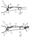
- FIG. 5 a joint device is shown, in which the effective direction in comparison to the embodiment according to FIG. 4 is turned around.
- the spring 54 is disposed around the piston rod 53, the interlocking element 531 is oriented as well as the arrangement of the teeth in the rack 59 in the opposite direction, so that there is an extension support.
- the piston 52 is pulled out at flexion and aids expansion if the valve 58 allows piston movement to assist the spring 54. This can be done in particular in the reversal of the flexion movement in an extension movement.
- the rack 59 or ratchet can be mechanically decoupled or the valve 58 can engage in a damping manner.
- FIG. 6 a further variant of the invention is shown, in which during the flexion of the joint, a spring 6 is compressed via a curved path 7 in order to release the energy in a further diffraction.
- kinetic energy can be stored during a flexion movement, for example during the heel strike, and returned to the hinge device 1 to initiate the swing phase in support of the flexion movement and / or to maintain the flexion velocity after toe off 6 due to the leadership in the curved path 7 ineffective.
- FIG. 7 Another variant of the hinge device 1 is in the FIG. 7 shown.
- a flywheel 8 is provided, which is accelerated in the flexion of the lower part 3 relative to the upper part 2.
- the flywheel mass 8 releases the rotational energy again, so that after reaching the maximum flexion speed, ie after the "toe off” or swinging through in the extension phase, energy is supplied to the joint device 1 in support of the respective movement.
- FIG. 8 is the device 5 for the conversion and storage of kinetic energy similar to the FIG. 4 constructed, but it lacks the positive locking element 531 at the upper end of the piston rod 53 and the rack 59.
- an extension control in particular to set the extension stop.
- the piston 52 When the joint device is fully stretched, the piston 52 is moved maximally into the lower chamber 55.
- the compression spring 54 is maximally tensioned.
- the energy stored in this way can be released when the valve 58 is opened for flexion support, so that support is provided for the initiation of flexion at the end of the stance phase.
- FIG. 9 a further variant of the invention.
- the energy conversion device 5 in addition to the embodiment according to FIG. 4 a second rack 593 and a second positive locking element 533 before.
- the second rack 593 is pivotally mounted on the lower part 3, the second positive locking element 533 acts on the spring 54 in the lower piston chamber 55.
- the piston 52 with the piston rod 53 is inserted through the rack 59 during the extension.
- the spring 54 stores the kinetic energy as potential energy.
- the piston rod side spring 541 or the piston rod distal spring 54 is compressed.
- the energy conversion device 5 may be associated with a speed-dependent clutch that provides reduced friction between power transmission elements at increased knee-angle velocities v, such that the conversion or storage rate is inversely proportional to the pivoting speed of the base 3 relative to the top 2.
- FIG. 10 shows an orthopedic joint device in the form of a prosthetic knee joint with an upper part 2, on which a thigh shaft 20 is arranged for receiving a thigh stump.
- a lower part 3 Distal to the upper part 2, a lower part 3 is hinged, so that the upper part 2 can be pivoted relative to a lower part 3.
- a boom 21 is rearwardly formed on the one hand, a damper device 50 in the form of a hydraulic or pneumatic damper and on the other hand, an energy storage 54 is arranged in the form of an elastic tendon.
- the elastic tendon is connected via a transmission gear 11 with an actuator 10 in the form of an electric motor.
- the electric motor is arranged in a lower leg tube, which is fastened to the lower part 3.
- the energy storage 5 in the form of the elastic tendon is attached to the transmission gear 11 and a boom 12, the motor 10 is activated, this acts on the transmission gear 11 on the boom 12 and can either stretch or relax the elastic tendon 54 by the boom 12 is displaced in the distal or proximal direction or twisted in one or the other direction to roll up or down the elastic tendon.
- the boom 12 thus forms a movable storage point of the energy storage device 5, whereby it is possible to set the beginning of a tensioning operation of the elastic tendon 54 during an extension movement of the lower part 3.
- a displaceable, elastic stretch stop can be realized, which is adjusted via the actuator 10.
- the stored energy can be released again to support the swing phase introduction, the elastic tendon 54 contracts and converts the position energy into mechanical work in order to support the flexion of the lower part 3.
- the actuator 10 biases the elastic tendon 54 by displacing the arm 12 distally or twisting it in the direction of retraction, to less energy stored, the boom 12 is displaced proximally or the tendon unrolled.
- the energy storage device 54 is at the same time the conversion device 5, in which the mechanical work is converted from the relative movement into potential energy.
- a separate damper 50 in the form of a hydraulic or pneumatic damper is provided which is adjustable, so that via the damper device 50, the damping during walking can be influenced both in the direction of flexion and extension direction.
- FIG. 11 A variant of the invention is in the FIG. 11 represented, in which instead of the relaxation or tension of the spring 54 substantially in its longitudinal extent a displacement takes place at the distal support point.
- the upper attachment point is guided in a displaceable spring connection 25, which via the actuator 10 in Direction of the double arrow is pushed back and forth.
- the elastic tendon 54 is tensioned or relaxed.
- the motor 10 Upon completion of the extension movement, it is possible for the motor 10 to subsequently re-tension the tendon 54 when the expected energy to be applied is insufficient to provide a desired support in flexion initiation.
- the re-tensioning is advantageously carried out when the joint device 1 is in a fully extended state in order to work as little as possible against a biasing movement.
- By adjusting either the bias of the elastic tendon 54 or the proximal storage position it is possible to set the draft angle, from which the conversion device 5 is active, which also sets how much energy to be stored in the energy storage 5.
- FIG. 12 a variant of the hinge device 1 is shown, in which the conversion device 5 is arranged in the form of the spring 54 in the lower leg tube.
- the actuator 10 is connected to the spring 5 and can either compress or wind it, depending on the design of the spring as a compression spring or coil spring.
- the spring 5 is coupled via a push rod 11 with a stop 16 which is fixed to the upper part 2.
- the base point of the spring 5 can be changed, which can be adjusted via the push rod 11, when the spring 5 comes into contact with the stopper 16.
- the spring 5 is either stretched or relaxed in the motion support.
- FIG. 13 represented essentially the FIG. 12
- the actuator 10 is optionally arranged with spindle drive and a freewheel in a direction between the spring 5 and the push rod 10, so that the base of the spring 5 remains fixed, but the spring 5 can be biased to the motor 10. If a Flexionsunterst Reifenung initiated, the motor 10 must rotate to release the energy and transmitted via the push rod 11 and the stop 16 on the hinge device, which can achieve a particularly good control over the energy release. It is also possible to stop energy release, which can be useful if a situation has been misjudged.
- a drill thread is shown as energy storage 54 and conversion means 5, in which a reduction of threads a shortening is achieved.
- the contact point can be set, from which the drill thread builds up tensile forces.
- an axial decoupling 13 is provided between the motor 10 and the twisting thread 54.
- this can also be optionally formed via a transmission gear and a generator as an electrical energy storage in the form of a battery, a rechargeable battery or a capacitor.
- a transmission gear and a generator for the reconversion of the stored electrical energy of the generator is switched as a motor, so that a drive and a support of the relative displacement of the lower part 3 can be made to the upper part 2.
- a generator can be assigned to the electrical energy storage, it is also possible to provide a further energy storage, which serves as a buffer, stored in the excess electrical energy or is provided from the additional energy required.
- the springs as energy storage 54 may be formed as tension springs, compression springs, torsion springs or elastomeric elements, which come in contact with a certain stretching angle, which is set by the actuator 10 and convert both mechanical work in energy from this point on and return to the motion support ,
- the spring absorbs the energy from the movement in the extension direction, and also serves as a braking device and extension stop. In the swing phase introduction, the energy is released again and helps the user to initiate the swing phase.
- the time of contact of the spring can be adjusted in the energy release, so that different, controlled supports at different walking speeds are possible.
- the respective spring is re-tensioned, if the energy stored by the previous movement is not sufficient to provide sufficient support, for example, during very slow walking or when leaving the stairs mechanical work is not sufficient to the To sufficiently tension the spring.
- the spring 5 can, as in the FIG. 12 shown to be associated with a release device 14, via which the triggering time for releasing the stored energy can be additionally hedged.
- the hinge device 1 may include a fuse formed by the hydraulics in the damper 50 or by a control of the motor 10 to ensure that the applied spring energy is dissipated in a timely manner.
- the motor support can work very sparingly.
- the battery for the actuator 10 may be small and light, as well as the actuator 10 itself, since the actuator 10 has sufficient time when retightening in the stance phase, the spring to tension and feeding the energy does not have to be as fast as the Levy for the swing phase introduction required.
- the motor 10 controls the release of energy from the spring, possibly in conjunction with the separate damper 20.
- the Flexionsunterstützung by the energy storage helps to achieve the necessary bending angle when climbing stairs and when climbing obstacles and saves hip work.
- FIG. 15 is exemplified the drive torque at different walking speeds on the joint angle ⁇ .
- the representation is made for three different walking speeds, the respective walking speeds being represented by different symbols in the diagram, the lowest walking speed being indicated by a triangle, the middle by a circle and the highest walking speed by an X.
- the driving torque is the effective driving torque in Nm, so stored by the memory device 5 and re-supplied energy minus the losses such as damping or Friction. It can be seen that initially a very high drive torque is used in order to be able to provide the flexion support initially.
- the applied drive torque initially drops steeply, remains constant over a small angular range, rises again briefly and then drops to zero until the maximum flexion. It can be seen that the flexion support is greater at low walking speeds, represented by the triangle, than at high walking speeds.
- the drive torque curve, as in the FIG. 15 is shown, can not be generated by a spring without a motor influence by retightening or relaxing, since according to the invention after the sharp drop in the drive torque over a further period, the moment is maintained until reaching the maximum angle.
- FIG. 16 shows a diagram in which the pulling path of the motor 10 is plotted against the joint angle ⁇ . Different speeds are listed, which are again indicated by a triangle, a circle and an X. The lowest walking speed is represented by a triangle.
- the illustration relates to the translatory movement of the motor 10 in the embodiments of Figures 10 . 12 and 14 ,
- the relocation route according to FIG. 16 is tuned so that the drive torque curve according to FIG. 15 can be achieved.
- the particular course is different for each selected spring and can lead to a larger or smaller displacement depending on the nature of the spring. The aim is to achieve the lowest possible displacement and thus tension of the spring.
- the motor allows the spring to slide back to achieve the fastest possible force reduction to further maintain the sense of controlled flexion.
- the spring is tensioned again to maintain or increase the force. Again, it is significant that at slow walking speeds increased support is needed. The release of the spring and thus the energy for flexion support and the drive of the motor occur simultaneously, so that over the entire course of the flexion support control is possible.
- FIG. 17 shows the change of the lever arm according to an embodiment of the FIG. 11 over the joint angle ⁇ for different walking speeds.
- the motor 10 is activated simultaneously with the spring release to adjust the lever arm.
- the lever arm is quickly reduced in size to cause a force reduction, then the lever arm is increased again to apply force ⁇ over a larger angular range and to support the flexion movement.
- the flexion damping setting of the damper device 50 is shown across the joint angle ⁇ at various speeds.
- the lowest walking speed is indicated by a square, the middle by a triangle and the highest walking speed by a rhombus.
- a mean flexion damping setting of the damper unit 50 is provided, which decreases with increasing joint angle ⁇ .
- an increase in the flexion damping can take place at the end of the swing phase in order to avoid excessive bending in of the lower part 3.
- the device can in principle also be used for extension support, the embodiments for flexion support apply accordingly also for an extension support, wherein it is also possible and provided that a flexion and extension support are arranged together in a joint device.
Abstract
Die Erfindung betrifft ein Verfahren zur Steuerung einer orthopädietechnischen Gelenkeinrichtung einer unteren Extremität, die Gelenkeinrichtung weist ein Oberteil (2) und ein gelenkig daran gelagertes Unterteil (3) auf, zwischen dem Oberteil (2) und dem Unterteil (3) ist eine Energieumwandlungseinrichtung (5) angeordnet, über die während des Gehens kinetische Energie aus der Relativbewegung zwischen dem Unterteil (3) und dem Oberteil (2) umgewandelt oder gespeichert und dem Gelenk wieder zugeführt wird, um die Relativbewegung zu unterstützen, wobei innerhalb eines Bewegungszyklus kinetische Energie umgewandelt und/oder gespeichert und innerhalb desselben Bewegungszyklus der Gelenkeinrichtung (1) gesteuert zeitversetzt als kinetische Energie wieder zugeführt wird, dadurch gekennzeichnet, dass die Speicherung und/oder Umwandlung der kinetischen Energie nur in vorbestimmten Phasen während eines Bewegungszyklus durchgeführt wird die Zufuhr gespeicherter Energie dadurch verändert wird, dass einem Energiespeicher (54) extern Energie zugeführt oder entzogen wird.The invention relates to a method for controlling an orthopedic articulation device of a lower extremity, the articulation device has an upper part (2) and a lower part (3) articulated thereto, between the upper part (2) and the lower part (3) is an energy conversion device (5 ) is converted, during which kinetic energy from the relative movement between the lower part (3) and the upper part (2) is converted or stored and returned to the joint, to support the relative movement, whereby kinetic energy is converted within one cycle of motion and / or stored and, within the same cycle of movement of the articulation device (1), is fed back as kinetic energy with a time delay, characterized in that the storage and / or conversion of the kinetic energy is carried out only in predetermined phases during a movement cycle, thereby changing the supply of stored energy is that an energy storage (54) externally supplied or withdrawn energy.
Description
Die Erfindung betrifft ein Verfahren zur Steuerung einer orthopädietechnischen Gelenkeinrichtung einer unteren Extremität sowie eine orthopädietechnische Gelenkeinrichtung als solche, die Gelenkeinrichtung weist ein Oberteil und ein gelenkig daran gelagertes Unterteil auf, zwischen dem Oberteil und dem Unterteil ist eine Dämpfereinrichtung angeordnet, über die die Extensionsdämpfung und/oder die Flexionsdämpfung der Schwenkbewegung bewirkt wird, wobei während des Gehens kinetische Energie aus der Relativbewegung zwischen dem Unterteil und dem Oberteil umgewandelt und gespeichert und dem Gelenk wieder zugeführt wird, um die Relativbewegung zu unterstützen.The invention relates to a method for controlling a orthopedic joint device of a lower extremity and an orthopedic articulation device as such, the hinge device has an upper part and a hinged thereto lower part, between the upper part and the lower part is arranged a damper device via which the extension damping and / or the flexion damping of the pivotal movement is effected, wherein during walking kinetic energy from the relative movement between the base and the shell is converted and stored and returned to the joint to assist the relative movement.
Orthopädietechnischen Gelenkeinrichtungen einer unteren Extremität sind beispielsweise Orthesen oder Prothesen. Insbesondere bei Prothesen, die ein natürliches Kniegelenk ersetzen, ist es vorteilhaft und vorgesehen, dass eine aktive Beeinflussung des Flexions- und Extensionswiderstandes im Verlaufe des Bewegungszyklus erfolgt, um das Verhalten der Gelenkeinrichtung an das Bewegungsverhalten oder an andere Einflüsse anzupassen.Orthopedic articulation devices of a lower extremity are, for example, orthoses or prostheses. In particular, in prostheses, which replace a natural knee joint, it is advantageous and provided that an active influence of the flexion and extension resistance in the course of the movement cycle takes place in order to adapt the behavior of the joint device to the movement behavior or other influences.
Darüber hinaus ergibt es motorisch angetriebene Prothesen oder Orthesen, deren Antriebsmotoren dazu dienen eine Flexion oder Extension der jeweiligen Gelenkeinrichtung auszuführen.In addition, there are motor-driven prostheses or orthoses whose drive motors serve to perform a flexion or extension of the respective joint device.
Die
Die
Aufgabe der vorliegenden Erfindung ist es daher, ein Verfahren und eine Einrichtung bereitzustellen, mit denen es möglich ist, eine Verbesserung des Gangbildes zu erreichen, ohne dass der Nutzer gefährdet wird und er eine schwere Gelenkeinrichtung tragen muss.It is therefore an object of the present invention to provide a method and a device with which it is possible to achieve an improvement of the gait image without the user being endangered and having to carry a heavy joint device.
Erfindungsgemäß wird diese Aufgabe durch ein Verfahren mit den Merkmalen des Hauptanspruches und eine orthopädietechnische Gelenkeinrichtung mit den Merkmalen des nebengeordneten Anspruchs gelöst. Vorteilhafte Ausgestaltungen und Weiterbildungen der Erfindung sind in den jeweils abhängigen Unteransprüchen, der Beschreibung und in den Figuren aufgeführt.According to the invention, this object is achieved by a method having the features of the main claim and an orthopedic articulation device with the features of the independent claim. Advantageous embodiments and further developments of the invention are set forth in the respective dependent subclaims, the description and in the figures.
Das erfindungsgemäße Verfahren zur Steuerung einer orthopädietechnischen Einrichtung einer unteren Extremität, bei der die Gelenkeinrichtung ein Oberteil und ein gelenkig daran gelagertes Unterteil aufweist und zwischen dem Oberteil und dem Unterteil eine Energieumwandlungseinrichtung angeordnet ist, über die während des Gehens kinetische Energie aus der Relativbewegung zwischen dem Unterteil und dem Oberteil umgewandelt und/oder gespeichert und dem Gelenk wieder zugeführt wird, um die Relativbewegung zu unterstützen, sieht vor, dass innerhalb eines Bewegungszyklus kinetische Energie umgewandelt und/oder gespeichert wird und innerhalb desselben Bewegungszyklus der Gelenkeinrichtung zeitversetzt als kinetische Energie wieder zugeführt wird. In einem typischen Bewegungszyklus einer orthopädietechnischen Gelenkeinrichtung einer unteren Extremität, also in einem typischen Schrittzyklus, existieren Phasen, in denen überschüssige Energie umgewandelt werden muss, aber auch Phasen, in denen eine Unterstützung mit kinetischer Energie sinnvoll ist. Es ist daher vorgesehen, dass überschüssige Energie, die zum Abbremsen einer Komponente der Gelenkeinrichtung gespeichert oder umgewandelt und gespeichert wird, im selben Schrittzyklus an geeigneter Stelle wieder zugeführt wird, wobei zwischen dem Speichern bzw. Umwandeln und Speichern und der erneuten Zuführung als kinetische Energie ein Zeitversatz vorliegt, also sich die Rückführung nicht unmittelbar an die Speicherung anschließt. Aufgrund der Zuführung der umgewandelten oder gespeicherten Energie in demselben Bewegungszyklus ist ein großer Akkumulator oder Kondensator unnötig, da nur relativ geringe Energiemengen vorhanden sind. Dadurch wird Gewicht eingespart und die Gelenkeinrichtung kann leicht gehalten werden. Die Einrichtung zur Umwandlung und/oder Speicherung kinetischer Energie kann als Teil einer Dämpfereinrichtung ausgebildet sein und einen Teil der Extensionsdämpfung und/oder die Flexionsdämpfung der Schwenkbewegung bewirken, wenn Energie umgewandelt oder gespeichert wird. Die Einrichtung kann als Hydraulikdämpfer und/oder Pneumatikdämpfer ausgebildet sein, ebenfalls kann eine Ausgestaltung als Generator vorgesehen sein. Möglich sind auch Kombinationen der vorbeschriebenen Einrichtungen miteinander. Die Einrichtung zur Umwandlung und/oder Speicherung kinetischer Energie kann neben herkömmlichen Dämpfereinrichtungen vorgesehen sein. Die übrigen Dämpfungskomponenten, in der Regel pneumatische oder hydraulische Dämpfer, bleiben weiter erhalten, jedoch ist zusätzlich entweder ein Kraftspeicher oder ein Generator, der umschaltbar als Motor betreibbar ist, vorgesehen, um an den geeigneten Stellen innerhalb der Bewegung kinetischer Energie aus dem System zu nehmen oder dem System zuzuführen. Aufgrund der Tatsache, dass das hydraulische oder pneumatische Dämpfungssystem einen großen Anteil der Energie dissipiert, kann das System zur Unterstützung der Bewegung klein und leicht gehalten werden. Der Zeitpunkt der Energieumwandlung und Rückführung wird über eine Steuereinrichtung festgelegt.The method according to the invention for controlling an orthopedic device of a lower extremity, in which the articulation device has an upper part and an articulated lower part and between the upper part and the lower part an energy conversion device is arranged, via which kinetic energy from the relative movement between the lower part during walking and the upper part is converted and / or stored and returned to the joint to support the relative movement, provides that kinetic energy is converted and / or stored within a cycle of motion and within the same cycle of movement of the joint device is fed back as kinetic energy. In a typical movement cycle of a lower limb orthopedic articulation device, that is to say in a typical step cycle, there are phases in which excess energy has to be converted, but also phases in which support with kinetic energy makes sense. It is therefore envisaged that surplus energy stored or converted and stored to decelerate a component of the hinge device is re-supplied in the same step cycle at a suitable location, between kinasing and storage and refeeding as kinetic energy There is a time offset, so the return is not directly connected to the storage. Due to the supply of the converted or stored energy in the same cycle of motion, a large accumulator or capacitor is unnecessary, since only relatively small amounts of energy are present. As a result, weight is saved and the hinge device can be easily held. The means for converting and / or storing kinetic energy may be formed as part of a damper means and cause a portion of the extension damping and / or the flexion damping of the pivotal movement when energy is converted or stored. The device can be designed as a hydraulic damper and / or pneumatic damper, also a configuration may be provided as a generator. Also possible combinations of the above-described facilities with each other. The means for converting and / or storing kinetic energy may be provided besides conventional damper means. The remaining damping components, typically pneumatic or hydraulic dampers, are still maintained, but in addition either an energy store or a generator, which is reversibly operable as a motor, is provided to remove kinetic energy from the system at the appropriate locations within the movement or to the system. Due to the fact that the hydraulic or pneumatic damping system dissipates a large proportion of the energy, the system for supporting the movement can be kept small and light. The time of energy conversion and recycling is determined by a controller.
Eine Weiterbildung der Erfindung sieht vor, dass kinetische Energie während einer Extensionsbewegung umgewandelt und/oder gespeichert wird. Die erneute Zuführung kinetischer Energie kann bei der Einleitung der Schwungphase zur Unterstützung der Schwungphasenflexion erfolgen. Ebenfalls kann nach der Zehenablösung ("toe off') während des Schrittes zur Aufrechterhaltung der Flexionsgeschwindigkeit kinetische Energie wieder zugeführt werden. Auch ist vorgesehen, dass nach dem Erreichen des maximalen Flexionswinkels, der beispielsweise durch eine Bewegungsumkehr oder durch einen Geschwindigkeitssensor ermittelt werden kann, zur Unterstützung der Extensionsbewegung Energie zugeführt werden. Auch kann nach der Flexionsbewegung nach dem initialen Fersenkontakt, also nach der Standphasenflexion, zur Unterstützung der Extensionsbewegung die kinetische Energie erneut zugeführt werden. Grundsätzlich ist es möglich, dass die Zuführung nur bei einer einzelnen Phase der Schrittbewegung erfolgt, alternativ dazu kann zu mehreren oder allen beschriebenen Phasen oder Zeitpunkten der Schrittbewegung eine Zuführung kinetischer Energie erfolgen.A development of the invention provides that kinetic energy is converted and / or stored during an extension movement. The reintroduction of kinetic energy may be at the initiation of the swing phase to assist in the swing phase flexion. Also, after toe off, kinetic energy may be re-introduced during the flexion rate maintaining step, and it is contemplated that after reaching the maximum flexion angle, which may be determined by, for example, a reversal of motion or a rate sensor In addition, after the flexion movement after the initial heel contact, ie after the stance phase flexion, the kinetic energy can be supplied again to support the extension movement. Alternatively, a supply of kinetic energy can take place at several or all phases or points in time of the step movement described.
Weiterhin kann vorgesehen sein, dass kinetische Energie während der Flexionsbewegung umgewandelt und/oder gespeichert wird und zur Einleitung der Schwungphase zur Unterstützung der Flexionsbewegung und/oder zur Aufrechterhaltung der Beugegeschwindigkeit nach der Zehenablösung wieder zugeführt wird. Daher kann vorgesehen sein, dass die kinetische Energie nach Einleitung der Schwungphase umgewandelt und/oder gespeichert wird und erst nach Erreichen der maximalen Flexionsgeschwindigkeit zur Unterstützung der Beugebewegung wieder zugeführt wird. Die Erreichung der maximalen Flexionsgeschwindigkeit kann durch einen Geschwindigkeitssensor oder einen Beschleunigungssensor ermittelt werden.Furthermore, it can be provided that kinetic energy is converted and / or stored during the flexion movement and is fed back to initiate the swing phase to support the flexion movement and / or to maintain the flexion speed after the toe release. Therefore, it can be provided that the kinetic energy is converted and / or stored after initiation of the swing phase and is supplied again only after reaching the maximum flexion speed in support of the flexion movement. The attainment of the maximum flexion speed can be determined by a speed sensor or an acceleration sensor.
In der Regel wird die Extensionsbewegung vor Erreichen der maximalen Extension abgebremst, um den Impuls zu mindern, der bei einem ungebremsten Aufprallen in den Extensionsanschlag vorliegt. Diese kinetische Energie kann umgewandelt und/oder gespeichert und zur Einleitung und/oder Unterstützung der Flexion der Gelenkeinrichtung wieder zugeführt werden. Während der Schwungphase der Gelenkeinrichtung kann kinetische Energie zur Erhöhung oder zur Aufrechterhaltung der Extensionsgeschwindigkeit zugeführt werden, um das Vorbringen des Unterteils zu erleichtern und zu unterstützen.As a rule, the extension movement is decelerated before reaching the maximum extension, in order to reduce the momentum which occurs in the extension stop during an unrestrained impact. This kinetic energy can be converted and / or stored and fed back to initiate and / or assist the flexion of the hinge device. During the swing phase of the joint device For example, kinetic energy can be added to increase or maintain the rate of extension to facilitate and assist sub-parting.
Weiterhin ist vorgesehen, dass kinetische Energie während der Standphase zu Beginn der Standphasenflexion bei Fersenbelastung, vor dem Erreichen des Extensionsanschlages und/oder nach der Einleitung der Standphasenflexion bei Vorfußbelastung umgewandelt und/oder gespeichert wird. Insbesondere kann die kinetische Energie bei dem initialen Fersenstoß umgewandelt und/oder gespeichert werden und zur Einleitung und/oder Unterstützung der Flexionsbewegung nach Erreichen eines Extensionsanschlages wieder zugeführt werden.Furthermore, it is provided that kinetic energy is converted and / or stored during the stance phase at the beginning of the stance phase flexion in the case of heel load, before the extension stop is reached and / or after the initiation of stance phase flexion with forefoot loading. In particular, the kinetic energy can be converted and / or stored at the initial heel strike and returned to initiate and / or assist the flexion movement upon reaching an extension stop.
Bei zunehmender Gehgeschwindigkeit kann vorgesehen sein, dass weniger kinetische Energie dem Gelenk zugeführt wird, um das System nicht selbst zu verstärken und somit den Nutzer der orthopädietechnischen Gelenkeinrichtung dazu zu bringen, immer schneller zu gehen.With increasing walking speed can be provided that less kinetic energy is supplied to the joint in order not to reinforce the system itself and thus to make the user of the orthopedic joint device to go faster and faster.
Die kinetische Energie kann in elektrische Energie umgewandelt und zwischengespeichert oder in potentielle Energie umgewandelt und zwischengespeichert werden, beispielsweise durch Aufladen eines Kraftspeichers, beispielsweise einer Feder oder eines hydraulischen oder pneumatischen Druckspeichers.The kinetic energy can be converted into electrical energy and stored temporarily or converted into potential energy and temporarily stored, for example by charging an energy store, for example a spring or a hydraulic or pneumatic pressure accumulator.
Es ist weiterhin vorgesehen, dass die umgewandelte Energie in einem Bewegungszyklus vollständig der Gelenkeinrichtung wieder zugeführt wird, so dass keine über den Bewegungszyklus hinausgehende Speicherung der umgewandelten Energie erfolgt. Dadurch wird sichergestellt, dass nur die während des einen Bewegungszyklus vorliegende und umgewandelte Energie dem System wieder als kinetische Energie zugeführt werden kann. Dies kann dadurch erfolgen, dass nach der erkannten Wiederkehr einer charakterisierenden Größe des Bewegungszyklus die bis dahin gespeicherte Energie dissipiert wird oder die Energiemenge laufend über den letzten Bewegungszyklus kontrolliert wird.It is further provided that the converted energy in a movement cycle is completely fed back to the joint device, so that no beyond the movement cycle storage of the converted energy takes place. This ensures that only the energy present during the one cycle of motion and converted energy can be returned to the system as kinetic energy. This can be done by dissipating the previously stored energy after the detected recurrence of a characterizing quantity of the movement cycle, or by controlling the amount of energy continuously over the last cycle of movement.
Weiterhin kann vorgesehen sein, dass die Speicherung und/oder Umwandlung der kinetischen Energie nur in vorbestimmten Phasen während eines Bewegungszyklus durchgeführt wird, also dass die Energieumwandlungseinrichtung nicht ständig arbeitet, um einen Teil der kinetischen Energie aus der Bewegung umzuwandeln, zu Speichern oder wider der Gelenkeinrichtung als kinetische Energie zuzuführen. Dazu werden entweder bestimmte Bewegungsphasen festgelegt, in denen immer eine Umwandlung, Speicherung oder Rückführung stattfindet, beispielsweise über eine mechanische oder elektrische Steuerungseinrichtung, oder die Zeitpunkte und Zeiträume, in denen eine Umwandlung, Speicherung oder Rückführung stattfindet, werden aufgrund einer Analyse der Bewegung anhand von Kenngrößen für jeden Bewegungszyklus oder für eine vorbestimmte oder errechnete Anzahl von Bewegungszyklen festgelegt. Dies kann beispielsweise über eine elektronische Steuereinrichtung erfolgen.Furthermore, it can be provided that the storage and / or conversion of the kinetic energy only in predetermined phases during a movement cycle is performed, so that the energy conversion device is not constantly working to convert a part of the kinetic energy from the movement to store or against the hinge device as kinetic energy. For this purpose, either certain motion phases are defined, in which there is always a conversion, storage or feedback, for example via a mechanical or electrical control device, or the times and periods in which a conversion, storage or feedback takes place, are based on an analysis of the movement based on Parameters for each movement cycle or for a predetermined or calculated number of movement cycles set. This can be done for example via an electronic control device.
Eine Weiterbildung des erfindungsgemäßen Verfahrens, bei dem während einer Verschwenkung des Oberteils relativ zu dem Unterteil mechanische Arbeit aus der Relativbewegung umgewandelt und in zumindest einem Energiespeicher gespeichert und der Gelenkeinrichtung zeitversetzt wieder zugeführt wird, um die Relativbewegung zu unterstützen, sieht vor, dass die gespeicherte Energie rückgewandelt und die Zufuhr mechanischer Arbeit zur und während der Unterstützung der Relativbewegung kontrolliert erfolgt. Bei einer Freigabe von Energie aus einem Energiespeicher, beispielsweise einer Feder, wird die gespeicherte Energie gemäß dem Stand der Technik schlagartig der Gelenkeinrichtung, also dem System aus Oberteil und Unterteil und gelenkiger Lagerung, zugeführt, so dass über einen sehr kurzen Zeitraum eine hohe Energiemenge eingeleitet wird. Es ist vorgesehen, dass die gespeicherte Energie kontrolliert dem System wieder zugeführt und in mechanische Arbeit und Unterstützung der Verlagerung von Oberteil zu Unterteil umgewandelt wird, um über einen längeren Zeitraum die Bewegung zu unterstützen, so dass eine an den natürlichen Bewegungsablauf angenäherte Bewegung der prothetischen oder orthetischen Einrichtung erfolgen kann. Eine Anpassung an veränderte Gangmuster, die Geschwindigkeiten oder unterschiedliche Patienten ist gemäß dem Stand der Technik nur außerordentlich aufwendig auszuführen, indem speziell angepasste Federn eingesetzt werden, was für den täglichen Einsatz unpraktikabel ist. Erfindungsgemäß wird dagegen die Energieabgabe in das System kontrolliert, so dass über einen vergleichsweise langen Zeitraum die benötigte Energiemenge eingespeist werden kann, um das Gangbild wie gewünscht zu beeinflussen.A further development of the method according to the invention, in which during a pivoting of the upper part relative to the lower part mechanical work from the relative movement is converted and stored in at least one energy storage and the hinge device is fed again delayed to support the relative movement, provides that the stored energy reversed and the supply of mechanical work is controlled to and during the support of the relative movement. With a release of energy from an energy storage device, such as a spring, the stored energy according to the prior art abruptly the joint device, ie the system of upper part and lower part and hinged storage, fed, so that initiated over a very short period of time a large amount of energy becomes. It is envisaged that the stored energy is returned to the system in a controlled manner and converted into mechanical work and support of displacement from top to bottom, to support the movement over a longer period of time, so that a movement of the prosthetic or natural movement approximated orthotic device can be done. An adaptation to changing gait patterns, the speeds or different patients is according to the prior art only extremely expensive to perform by specially adapted springs are used, which is impractical for daily use. According to the invention, however, the energy output is controlled in the system, so that over a relatively long period of time, the amount of energy required can be fed to affect the gait as desired.
Die Zufuhr der mechanischen Arbeit kann dadurch verändert werden, dass dem Energiespeicher extern Energie zugeführt oder entzogen wird. Handelt es sich bei dem Energiespeicher um eine Feder, kann die Zufuhr der Energie dadurch erfolgen, dass die Feder nachgespannt wird, das Entziehen oder das Verringern der Energiemenge kann dadurch erfolgen, dass die Feder entspannt wird, beispielsweise durch Verlagerung eines Federwiderlagers. Ist der Energiespeicher als elektrischer Energiespeicher, beispielsweise Kondensator, Batterie oder Akkumulator ausgebildet, kann die Veränderung der Energiemenge durch Aktivierung eines Generators oder Einleitung aus einem zweiten Energiespeicher erfolgen, die Verringerung der Energiemenge durch Anschließen eines Verbrauchers oder Umleitung in einen zweiten Speicher für elektrische Energie erfolgen.The supply of mechanical work can be changed by the fact that the energy storage externally supplied or withdrawn energy. If the energy store is a spring, the supply of energy can take place in that the spring is re-tensioned, the removal or reduction of the amount of energy can be effected by relaxing the spring, for example by displacing a spring abutment. If the energy store is embodied as an electrical energy store, for example a capacitor, battery or accumulator, the change in the amount of energy can be effected by activation of a generator or initiation from a second energy store, reducing the amount of energy by connecting a consumer or diverting it into a second store for electrical energy ,
Eine Weiterbildung der Erfindung sieht vor, dass dem Energiespeicher ein Aktuator zugeordnet ist, über den der Energiespeicher auf ein Mindestniveau befüllt oder gebracht wird, wenn die Relativbewegung dazu nicht ausreicht. Sollte die durch die Bewegung verfügbare Energie nicht ausreichen, um den Energiespeicher für den nächsten Schritt oder den Bewegungsablauf mit ausreichend Energie zu versorgen, wobei die Mindestmenge in Abhängigkeit von der Gehgeschwindigkeit, der Gehsituation und den individuellen Gegebenheiten eines Patienten abhängen, ist erfindungsgemäß vorgesehen, dass während des Gehens und vor der Rückführung von Energie zur Unterstützung der Relativbewegung der Energiespeicher auf ein festgelegtes Niveau aufgefüllt wird, beispielsweise durch Spannen einer Feder oder durch Antreiben eines Generators, der den elektrischen Energiespeicher auflädt.A development of the invention provides that the energy store is associated with an actuator, via which the energy storage is filled or brought to a minimum level, if the relative movement is not sufficient. If the energy available by the movement is insufficient to supply the energy store with sufficient energy for the next step or the sequence of movements, the minimum quantity depending on the walking speed, the walking situation and the individual circumstances of a patient, it is provided according to the invention is supplemented during walking and before the return of energy to support the relative movement of the energy storage to a predetermined level, for example by tensioning a spring or by driving a generator that charges the electrical energy storage.
Um den Zeitpunkt der Bewegungsunterstützung präzise bestimmen zu können ist erfindungsgemäß vorgesehen, dass dem Energiespeicher eine Freigabeeinrichtung zugeordnet ist, über die die Energie aus dem Energiespeicher teilweise oder vollständig freigegeben wird. Die Freigabeeinrichtung bestimmt den Zeitpunkt der Energieabgabe, die Dauer und den Verlauf der Energieabgabe wird bei einer vollständigen Freigabe nicht über die Freigabeeinrichtung gesteuert, sondern über Veränderungen in dem Energiespeicher, also durch Entzug oder Zufuhr von Energie. Bei einer teilweisen Freigabe erfolgte eine Reduzierung der abgegebenen Energiemenge, so dass das Anfangsniveau der Bewegungsunterstützung eingestellt werden kann. Über eine teilweise Freigabe kann eine Anpassung beispielsweise an Gehgeschwindigkeiten, Patienten oder Gehsituationen vorgenommen werden, die Feinbeeinflussung der Unterstützung erfolgt über die Veränderung im Energiespeicher.In order to be able to precisely determine the time of the movement support, it is provided according to the invention that the energy store is assigned a release device, via which the energy from the energy store is partially or completely released. The release device determines the time of the energy delivery, the duration and the course of the energy delivery is not controlled by the release device at a complete release, but via changes in the energy storage, ie by withdrawal or supply of energy. In a partial release, a reduction of the amount of energy delivered, so that the initial level of motion support can be adjusted. about a partial release can be made, for example, to walking speeds, patients or walking situations, the fine-tuning of the support takes place via the change in the energy store.
Die Energie kann als mechanische Arbeit in Abhängigkeit von zumindest einem folgenden Kriterium oder einer Kombination mehrerer folgenden Kriterien zugeführt werden, nämlich der Winkelstellung des Oberteils zu dem Unterteil, der Position des Oberteils und/oder des Unterteils im Raum, einer Winkelgeschwindigkeit des Oberteils und/oder des Unterteils, der Relativgeschwindigkeit zwischen Oberteil und Unterteil, der Belastungssituation und/oder der Beschleunigung des Oberteils und/oder des Unterteils. Dadurch ist es möglich, dass eine möglichst genaue zeitliche und mengenmäßige Unterstützung der Bewegung erfolgt. Die Stellungen der Oberteile und Unterteile zueinander und im Raum können durch Winkelsensoren oder Inertialsensoren bestimmt werden, die Geschwindigkeiten zueinander oder innerhalb des Raumes durch Beschleunigungssensoren oder einer Kombination aus Winkelsensor und Beschleunigungssensor. Über die Sensoren lässt sich nicht nur der Zeitpunkt der Freigabe der Energie, sondern auch die jeweilige Gangsituation, die Gehgeschwindigkeit sowie die aktuelle Position der jeweiligen Komponenten zueinander oder im Raum bestimmen, worüber es ermöglicht wird, die Menge und den Verlauf der Energiezufuhr zur Unterstützung der Bewegung zu bestimmen und zu steuern.The energy may be supplied as mechanical work as a function of at least one of the following criteria or a combination of several of the following criteria, namely the angular position of the upper to the lower part, the position of the upper part and / or the lower part in space, an angular velocity of the upper part and / or the lower part, the relative speed between the upper part and lower part, the loading situation and / or the acceleration of the upper part and / or the lower part. This makes it possible to provide the most accurate time and quantity support possible for the movement. The positions of the tops and bottoms to each other and in space can be determined by angle sensors or inertial sensors, the speeds to each other or within the space by acceleration sensors or a combination of angle sensor and acceleration sensor. The sensors can be used not only to determine the time of the energy release, but also the respective gait situation, the walking speed and the current position of the respective components relative to each other or in space, thereby enabling the amount and course of the energy supply to support the energy supply To determine and control movement.
Eine Weiterbildung der Erfindung sieht vor, dass die Energie dem Energiespeicher in Abhängigkeit von zumindest einem oder mehreren der oben aufgeführten Kriterien zugeführt oder entzogen wird, um die kontrollierte Steuerung der Bewegung durchzuführen.A further development of the invention provides that the energy is supplied or withdrawn from the energy store as a function of at least one or more of the criteria listed above in order to carry out the controlled control of the movement.
Der Zeitpunkt des Ineingrifftretens der Umwandlungseinrichtung zur Veränderung der umzuwandelnden Energiemenge und/oder der zugeführten Energiemenge kann verstellt werden, so dass beispielsweise in Abhängigkeit von der Gehgeschwindigkeit, der Gehsituation oder den individuellen Parametern des Patienten eingestellt werden kann, wie groß die zu speichernde Energiemenge ist oder wie groß die abzugebende Energiemenge sein muss. Bei einer gewünschten großen Energiemenge ist es vorgesehen, dass ein möglichst früher Eingriff bei der Umwandlung stattfindet, so dass beispielsweise ein Generator sehr früh und sehr lang angetrieben wird oder eine Feder sehr weit vorgespannt wird, um die mechanische Arbeit beim Gehen, beispielsweise beim Fersenauftritt in der Standphasenflexion, maximal in die Lageenergie einer Feder oder elektrische Energie eines Akkumulators oder eines Kondensators umzuwandeln. Wird der Zeitpunkt des Eingriffs bei der Rückwandlung verstellt, beispielsweise durch Verlagerung eines Anschlages oder einer winkelabhängigen Freigabe, wird die Energie zu einem späteren Zeitpunkt des Schrittes eingeleitet, wodurch sich eine Veränderung des Gangbildes erreichen lässt. Der Energiespeicher kann von einem Aktuator aufgeladen werden, wenn die Umwandlungseinrichtung nicht aufgrund der Relativbewegung zwischen dem Oberteil und dem Unterteil aktiv ist, so dass der Aktuator nicht gegen die Relativbewegung arbeiten muss. Darüber hinaus hat die zeitliche Einordnung der Aufladung des Energiespeichers durch den Aktuator in eine Phase, in der keine mechanische Arbeit aus der Gelenkeinrichtung umgewandelt wird, den Vorteil, dass über einen langen Zeitraum Energie eingespeichert werden kann, was dazu führt, dass der Aktuator entsprechend klein dimensioniert werden kann, um über einen großem Zeitraum die gewünschte Menge bereitstellen zu können. Wird beispielsweise eine Feder über einen Motor als Aktuator gespannt, kann dieser klein ausgelegt werden und mit einer Übersetzung mit der Feder gekoppelt werden, so dass über einen vergleichsweise großen Zeitraum die Feder gespannt werden kann. Gleiches gilt für die Umwandlung und Speicherung elektrischer Energie.The time of engagement of the conversion device for varying the amount of energy to be converted and / or the amount of energy supplied can be adjusted, so that, for example, depending on the walking speed, the walking situation or the individual parameters of the patient can be set, how large the amount of energy to be stored how big the amount of energy has to be delivered With a desired large amount of energy, it is envisaged that an intervention takes place as early as possible in the conversion, so that For example, a generator is driven very early and very long or a spring is biased very far to convert the mechanical work while walking, for example, when heel occurrence in the stance phase flexion, maximum in the position energy of a spring or electrical energy of a battery or a capacitor. If the time of the engagement in the reconversion is adjusted, for example by shifting a stop or an angle-dependent release, the energy is introduced at a later time of the step, whereby a change in the gait pattern can be achieved. The energy storage device can be charged by an actuator if the conversion device is not active due to the relative movement between the upper part and the lower part, so that the actuator does not have to work against the relative movement. In addition, the timing of the charging of the energy storage by the actuator in a phase in which no mechanical work is converted from the hinge device, the advantage that over a long period of energy can be stored, resulting in that the actuator is correspondingly small can be dimensioned to provide over a long period of time the desired amount. If, for example, a spring is tensioned via an engine as an actuator, it can be designed to be small and coupled with a transmission with the spring so that the spring can be tensioned over a comparatively large period of time. The same applies to the conversion and storage of electrical energy.
Eine Weiterbildung der Erfindung sieht vor, dass die Relativbewegung zusätzlich zu der Beeinflussung des Energiespeichers über eine Dämpfereinrichtung beeinflusst wird, so dass nicht ausschließlich über den Energiespeicher die Steuerung erfolgen muss, was dazu führt, dass eine große Variationsmöglichkeit bei der Beeinflussung des Gangbildes vorliegt. Darüber hinaus können Belastungsspitzen über eine zusätzliche Dämpfereinrichtung leichter aufgefangen werden.A development of the invention provides that the relative movement is influenced in addition to the influence of the energy storage device via a damper device, so that the control does not have to be exclusively via the energy store, which leads to a great possibility of variation in influencing the gait pattern. In addition, load peaks can be more easily absorbed via an additional damper device.
Die orthopädietechnische Gelenkeinrichtung der unteren Extremität mit einem Oberteil und einem gelenkig daran gelagerten Unterteil und eine Einrichtung zur Umwandlung und/oder Speicherung kinetischer Energie sieht vor, dass die Speichereinrichtung eine Umwandlungs- und/oder Speicherungsrate aufweist, die umgekehrt proportional zu der Verschwenkgeschwindigkeit des Unterteils relativ zu dem Oberteil ist.The lower limb orthopedic articulation device having a top and a hinged base and a means for converting and / or storing kinetic energy provides that the storage device has a conversion and / or storage rate that is inversely proportional to the pivoting speed of the base relative to the top is.
Dadurch wird gewährleistet, dass trotz der eigentlich zunehmenden, umzuwandelnden kinetischen Energie keine Selbstverstärkung erfolgt, so dass das System der Gelenkeinrichtung stabil bleibt.This ensures that, in spite of the actually increasing kinetic energy to be converted, no self-reinforcement takes place, so that the system of the joint device remains stable.
Es können ein Generator zur Erzeugung elektrischer Energie und ein Motor zum Antreiben des Unterteils vorgesehen sein, wobei dem Generator eine geschwindigkeitsabhängige Kupplung vorgeschaltet ist, die den Generator mit einer Antriebseinrichtung verbindet. Je höher die Bewegungsgeschwindigkeit ist, desto geringer ist die Leistung, die über die Kupplung übertragen wird, so dass die umgekehrte Proportionalität der Energieerzeugung im Verhältnis zur Verschwenkgeschwindigkeit über die Kupplung realisiert wird.There may be provided a generator for generating electrical energy and a motor for driving the lower part, wherein the generator is preceded by a speed-dependent coupling which connects the generator with a drive means. The higher the speed of movement, the lower the power transmitted through the clutch, so that the inverse proportionality of the power generation relative to the pivoting speed is realized via the clutch.
In der Gelenkeinrichtung kann eine Hydraulikdämpfereinheit zur Dämpfung der Verschwenkbewegung zwischen dem Unterteil und dem Oberteil angeordnet sein, wobei das Hydraulikfluid der Hydraulikdämpfereinheit als Aktuator zur Trennung der Kupplung dient. Die Kupplung kann als eine geschwindigkeitsabhängige Rutschkupplung ausgebildet sein.In the hinge device, a hydraulic damper unit for damping the pivoting movement between the lower part and the upper part may be arranged, wherein the hydraulic fluid of the hydraulic damper unit serves as an actuator for separating the clutch. The clutch may be formed as a speed-dependent slip clutch.
Als Speichereinrichtung für die kinetische Energie kann ein Schwungrad oder ein Druckspeicher vorgesehen sein. Die Gelenkeinrichtung ist bevorzugt als ein Hüftgelenk, Kniegelenk oder Fußgelenk einer Prothese oder Orthese ausgebildet. Der Energiespeicher kann auch als Feder oder Akkumulator ausgebildet sein, wobei unter einem Akkumulator auch ein Kondensator oder eine aufladbare Batterie verstanden wird.As a storage device for the kinetic energy, a flywheel or a pressure accumulator may be provided. The joint device is preferably designed as a hip joint, knee joint or ankle of a prosthesis or orthosis. The energy storage device can also be designed as a spring or accumulator, wherein a rechargeable battery is also understood to mean a capacitor or a rechargeable battery.
Eine Weiterbildung der orthopädietechnischen Gelenkeinrichtung sieht vor, dass dem Energiespeicher ein Aktuator zugeordnet ist, der während der Unterstützung der Relativbewegung dem Energiespeicher kontrolliert Energie zuführt oder entzieht. Durch die kontrollierte Zufuhr oder den kontrollierten Entzug von Energie aus dem Energiespeicher über einen Aktuator ist eine besonders einfache und zuverlässige Beeinflussung des Gangbildes bei semiaktiven Gelenkeinrichtungen, insbesondere bei semiaktiven Prothesenkniegelenkten möglich. Die Umwandlungseinrichtung kann als Feder oder Generator ausgebildet sein, um die mechanische Arbeit, die bei einer Relativbewegung zwischen dem Oberteil und dem Unterteil anfällt, entweder in Lageenergie in einer Feder oder elektrische Energie in einer elektrischen Speichereinrichtung, beispielsweise in Gestalt eines Akkumulators, in einer aufladbaren Batterie oder in einem Kondensator zu speichern.A further development of the orthopedic articulation device provides that the energy store is associated with an actuator which supplies or withdraws energy during the support of the relative movement of the energy store in a controlled manner. The controlled supply or the controlled withdrawal of energy from the energy store via an actuator allows a particularly simple and reliable influencing of the gait pattern in semi-active joint devices, in particular in the case of semi-active prosthetic knee joints. The conversion device may be designed as a spring or generator to the mechanical work, in a relative movement accumulates between the upper part and the lower part, either in position energy in a spring or electrical energy in an electrical storage device, for example in the form of a rechargeable battery, to store in a rechargeable battery or in a capacitor.
Eine separate Dämpfereinrichtung kann zwischen dem Oberteil und dem Unterteil angeordnet sein, um die Relativbewegung bei Unterstützung durch den Energiespeicher besser kontrollieren zu können. Durch die Überlagerung der Beeinflussung des Energiespeichers mit der separaten Dämpfereinrichtung kann eine präzisere und sichere Beeinflussung des Gangbildes erfolgen. Die Dämpfereinrichtung kann verstellbar ausgebildet sein, um in Abhängigkeit von Sensordaten, beispielsweise bezüglich des Gelenkwinkels, der Ganggeschwindigkeit, einer Winkelgeschwindigkeit oder eines Absolutwinkels eines Oberteils und/oder eines Oberteils eine angepasste Dämpfung bereitzustellen. Die Dämpfereinrichtung kann über einen Aktuator verstellt werden, um eine Verringerung oder Vergrößerung der Dämpfung zu erreichen.A separate damper device may be arranged between the upper part and the lower part in order to be able to better control the relative movement when supported by the energy store. By superimposing the influence of the energy store with the separate damper device, a more precise and reliable influencing of the gait pattern can take place. The damper device may be designed to be adjustable in order to provide adapted damping as a function of sensor data, for example with regard to the joint angle, the gear speed, an angular speed or an absolute angle of a top part and / or a top part. The damper device can be adjusted via an actuator in order to achieve a reduction or increase in the damping.
Die Umwandlungseinrichtung kann verstellbar mit dem Oberteil und/oder mit dem Unterteil gekoppelt sein, um eine Eingriffsposition oder einen Verstellweg zu verlagern. Dadurch ist es möglich, sowohl die Energiemenge als auch den Zeitpunkt der Energiezufuhr wie gewünscht zu beeinflussen.The conversion means may be adjustably coupled to the top and / or the bottom to displace an engagement position or an adjustment path. This makes it possible to influence both the amount of energy and the time of energy supply as desired.
Mit dem beschriebenen Verfahren und der beschriebenen Einrichtung ist es möglich, dass benötigte Energie nur an geeigneter Stelle während des Bewegungsablaufes und in minimaler Menge zugeführt wird. Der Nutzer der orthopädietechnischen Einrichtung bringt weiterhin den größten Teil der Bewegungsenergie ein, beispielsweise über den verbliebenen Stumpf. Notwendig oder zumindest vorteilhaft ist eine Energiezufuhr jedoch an zwei Punkten, an denen der Nutzer der Gelenkeinrichtung über seine Muskeln die benötigte Energie nicht einbringen kann, beispielsweise weil die Muskelkraft nicht ausreicht, wenn wegen der Massenträgheiten sehr hohe Beschleunigungen erforderlich sind. So ist beispielsweise eine Unterstützung in der Schwungphase beim Überschwingen über den Boden sinnvoll, damit verhindert wird, dass das Unterteil beim Gehen auf dem Boden schleift. Über eine gezielte Energiezufuhr kann der Kniewinkel erhöht werden, sodass mehr Bodenfreiheit realisiert wird. Beim alternierenden Treppaufgehen kann ein zusätzliches Extensionsmoment den Benutzer befähigen, den Rest der Stufe aus eigener Kraft zu überwinden.With the described method and the device described, it is possible that required energy is supplied only at a suitable location during the movement sequence and in a minimal amount. The user of the orthopedic device continues to bring most of the kinetic energy, for example on the remaining stump. Necessary or at least advantageous, however, is an energy supply at two points at which the user of the joint device can not bring in the required energy via his muscles, for example because the muscular strength is insufficient if very high accelerations are required because of the inertial masses. For example, support in the swing phase when overshooting over the ground makes sense, so that the lower part is prevented from dragging on the ground when walking. About a targeted energy intake can the knee angle can be increased so that more ground clearance is realized. With alternate stair climbing, an additional extension moment can empower the user to overcome the rest of the step on their own.
Aufgrund der Tatsache, dass immer nur die minimal nötigen Energien als kinetische Energie in das System eingespeist werden, behält der Nutzer jederzeit die Kontrolle über die orthopädietechnische Einrichtung. Die jeweils gespeicherte Energie würde nicht ausreichen, um den Benutzer in eine kritische Lage zu bringen. Darüber hinaus wird die Entstehung muskulärer Defizite vermieden, da der Benutzer weiterhin die Bewegungsenergie selbst aufbringen muss, lediglich die Feinsteuerung erfolgt über das Verfahren bzw. die Einrichtung.Due to the fact that only the minimum necessary energy is fed into the system as kinetic energy, the user always has control over the orthopedic equipment. The stored energy would not be enough to put the user in a critical position. In addition, the emergence of muscular deficits is avoided because the user must continue to apply the kinetic energy itself, only the fine control is done via the process or the device.
Nachfolgend werden Ausführungsbeispiele der Erfindung anhand der beigefügten Figuren näher erläutert. Es zeigen:
- Figur 1 -
- einen Kniewinkelverlauf während eines Gangzyklus;
- Figur 2 -
- der Verlauf der Kniewinkelgeschwindigkeit über einen Gangzyklus;
- Figur 3 -
- Phasen möglicher Energieaufnahmen und Abgaben des Kniegelenkes während des Gangzyklus;
- Figur 4 -
- eine schematische Darstellung einer Gelenkeinrichtung mit einer Energiespeichereinrichtung zur Flexionsunterstützung;
- Figur 5 -
- eine Gelenkeinrichtung mit einer Einrichtung zur Extensionsunterstützung;
- Figur 6 -
- eine Gelenkeinrichtung mit einer in einer Kurvenbahn gelagerten Feder;
- Figur 7 -
- eine Gelenkeinrichtung mit einer Schwungmasse als Energiespeicher;
- Figur 8 -
- eine Variante der Gelenkeinrichtung mit einer Extensionssteuerung;
- Figur 9 -
- eine Gelenkeinrichtung mit zwei Federn
Figur 10- eine Gelenkeinrichtung mit einer elastischen Sehne als Energiespeicher;
Figur 11- eine Variante der
Figur 1 mit einer verschieblichen Federanbindung; - Figur 12
- eine Variante mit einer im Unterteil angeordneten Feder;
- Figur 13
- eine Variante der
Figur 3 mit einem zwischengeschalteten Aktuator; Figur 14- eine Variante mit einem Drillfaden als Energiespeicher;
Figur 15- eine Darstellung von Antriebsmomentverläufen bei unterschiedlichen Gehgeschwind ig keiten;
Figur 16- eine Darstellung unterschiedlicher Verlagerungswege über einen Gelenkwinkel bei verschiedenen Gehgeschwindigkeiten;
- Figur 17
- eine Darstellung eines Hebelarmverlaufes über einen Gelenkwinkel; sowie
- Figur 18
- eine Darstellung einer Flexionsdämpfungseinstellung eines Dämpfers über einen Kniewinkel.
- FIG. 1 -
- a knee angle progression during a gait cycle;
- FIG. 2 -
- the course of the knee angular velocity over a gait cycle;
- FIG. 3 -
- Phases of possible energy intake and release of the knee joint during the gait cycle;
- FIG. 4 -
- a schematic representation of a hinge device with an energy storage device for inflection support;
- FIG. 5 -
- a hinge device with a device for extension support;
- FIG. 6 -
- a hinge device with a spring mounted in a cam track;
- FIG. 7 -
- a hinge device with a flywheel as energy storage;
- FIG. 8 -
- a variant of the hinge device with an extension control;
- FIG. 9
- a joint device with two springs
- FIG. 10
- a hinge device with an elastic tendon as energy storage;
- FIG. 11
- a variant of
FIG. 1 with a sliding spring connection; - FIG. 12
- a variant with a spring arranged in the lower part;
- FIG. 13
- a variant of
FIG. 3 with an intermediate actuator; - FIG. 14
- a variant with a drill thread as energy storage;
- FIG. 15
- an illustration of drive torque curves at different speeds Gegeschig;
- FIG. 16
- a representation of different displacement paths over a joint angle at different walking speeds;
- FIG. 17
- a representation of a Hebelarmverlaufes over a joint angle; such as
- FIG. 18
- a representation of a flexion damping setting of a damper over a knee angle.
In der
In der
Um schneller in den Bereich einer großen Kniebeugung zu gelangen, ist es möglich und notwendig, in bestimmten Abschnitten des Gangzyklus die Kniewinkelgeschwindigkeit zu erhöhen, beispielsweise um damit ein Durchschwingen des Beines zu erleichtern. Die maximale Kniebeugung kann dabei gleich bleiben oder aber vergrößert werden, wenn eine Extensionsunterstützung vorhanden ist, damit der Unterschenkel schnell genug nach vorne gebracht wird.In order to get into the area of a large knee flexion faster, it is possible and necessary to increase the knee angular velocity in certain sections of the gait cycle, for example to facilitate swinging of the leg. The maximum knee flexion can remain the same or be increased, if an extension support is present, so that the lower leg is brought fast enough forward.
In der
Als Zuführphasen i sind insbesondere die Extensionsbewegung nach dem initialen Fersenkontakt, die Unterstützung der Einbeugung zur Einleitung der Schwungphase, die Aufrechterhaltung der Flexionsgeschwindigkeit nach dem "toe off' sowie die Unterstützung der Flexionsbewegung nach dem Erreichen des maximalen Flexionswinkels vorgesehen.In particular, the extension movement after the initial heel contact, the support of the inflection to initiate the swing phase, the maintenance of the flexion speed after the toe off and the support of the flexion movement after reaching the maximum flexion angle are provided as supply phases i.
In der
In der
In der
Eine weitere Variante der Gelenkeinrichtung 1 ist in der
In der
In der
Der Energieumwandlungseinrichtung 5 kann eine geschwindigkeitsabhängige Kupplung zugeordnet sein, die bei erhöhten Kniewinkelgeschwindigkeiten v eine verminderte Reibung zwischen Kraftübertragungselementen bereitstellt, so dass die Umwandlungs- oder Speicherungsrate umgekehrt proportional zu der Verschwenkgeschwindigkeit des Unterteils 3 relativ zu dem Oberteil 2 ist.The
In der terminalen Standphase kann zur Unterstützung der Schwungphaseneinleitung die gespeicherte Energie wieder abgegeben werden, die elastische Sehne 54 zieht sich zusammen und wandelt die Lageenergie in mechanische Arbeit um, um die Flexion des Unterteils 3 zu unterstützen. Soll mehr Energie in dem Energiespeicher 54 gespeichert werden, spannt der Aktuator 10 die elastische Sehne 54 vor, indem der Ausleger 12 distal verlagert oder in Aufrollrichtung verdreht wird, soll weniger Energie gespeichert werden, wird der Ausleger 12 proximal verlagert oder die Sehne abgerollt. Im dargestellten Ausführungsbeispiel ist die Energiespeichereinrichtung 54 gleichzeitig die Umwandlungseinrichtung 5, in der die mechanische Arbeit aus der Relativbewegung in potenzielle Energie umgewandelt wird.In the terminal stance phase, the stored energy can be released again to support the swing phase introduction, the
Zusätzlich zu der Umwandlungseinrichtung 5 bzw. dem Energiespeicher 54 ist ein separater Dämpfer 50 in Gestalt eines Hydraulik- oder Pneumatikdämpfers vorgesehen, der verstellbar ausgebildet ist, so dass über die Dämpfereinrichtung 50 die Dämpfung während des Gehens sowohl in Flexionsrichtung als auch Extensionsrichtung beeinflusst werden kann.In addition to the
Zur kontrollierten Unterstützung bei der Schwungphaseneinleitung ist es vorgesehen, dass über den Aktuator 10, die Übersetzung 11 und die Verlagerung oder Verdrehung des Auslegers 12 eine Veränderung der Vorspannung der elastischen Sehne 54 erfolgt, um die Energieabgabe besser kontrollieren zu können. Es hat sich herausgestellt, dass eine Feder alleine als Kraftspeicher eine zu große und zu schnelle Krafteinleitung bewirkt, was von den Patienten als unangenehm empfunden werden kann. Um sowohl den Zeitraum der Energieeinleitung als auch die Energiemenge und die Leistung kontrollieren zu können, kann in Abhängigkeit von der Winkelstellung des Oberteils 2 zum Unterteil 3, der Winkelstellung des Oberteils 2 und/oder des Unterteils 3 zueinander oder im Raum, den Winkelgeschwindigkeiten oder der Ganggeschwindigkeit eine Manipulation am Energiespeicher 54 vorgenommen werden, um die Leistung zu begrenzen und darüber hinaus den zeitlichen Ablauf der Energieabgabe zu steuern. Durch Entspannen der Feder 54 ist es möglich, weniger Energie in die Gelenkeinrichtung 1 einzubringen, durch Nachspannen der Feder 54 ist es möglich, eine Unterstützung der Flexion über einen längeren Zeitraum hinweg und über einen größeren Flexionswinkel hinweg aufrechtzuerhalten, um das gewünschte harmonische Gangbild zu erreichen.For controlled support in the swing phase introduction, it is provided that via the
Eine Variante der Erfindung ist in der
In der
Eine Variante ist in der
In der
Neben der dargestellten Ausführungsform des Energiespeichers als Feder kann dieser auch gegebenenfalls über ein Übersetzungsgetriebe und einen Generator als elektrischer Energiespeicher in Gestalt einer Batterie, eines Akkumulators oder eines Kondensators ausgebildet sein. Zur Rückumwandlung der gespeicherten elektrischen Energie wird der Generator als Motor geschaltet, so dass ein Antrieb und eine Unterstützung der Relativverlagerung des Unterteils 3 zu dem Oberteil 2 erfolgen können. Zur Erhöhung der Energiemenge kann ein Generator dem elektrischen Energiespeicher zugeordnet sein, ebenso ist es möglich, einen weiteren Energiespeicher vorzusehen, der als Puffer dient, in den überschüssige elektrische Energie eingespeichert oder aus dem zusätzlich benötigte Energie bereitgestellt wird.In addition to the illustrated embodiment of the energy storage device as a spring, this can also be optionally formed via a transmission gear and a generator as an electrical energy storage in the form of a battery, a rechargeable battery or a capacitor. For the reconversion of the stored electrical energy of the generator is switched as a motor, so that a drive and a support of the relative displacement of the
Die Federn als Energiespeicher 54 können als Zugfedern, Druckfedern, Drehfedern oder Elastomerelemente ausgebildet sein, die ab einem bestimmten Streckwinkel, der von dem Aktuator 10 eingestellt wird, in Kontakt kommen und sowohl mechanische Arbeit in Energie ab diesem Zeitpunkt umwandeln als auch wieder zur Bewegungsunterstützung zurückführen. Die Feder nimmt dabei die Energie aus der Bewegung in Extensionsrichtung auf, und dient gleichzeitig als Bremseinrichtung und Extensionsanschlag. Bei der Schwungphaseneinleitung wird die Energie wieder abgegeben und hilft dem Nutzer, die Schwungphase einzuleiten. Über den Aktuator 10 kann der Zeitpunkt des Kontaktes der Feder bei der Energieabgabe verstellt werden, so dass unterschiedliche, kontrollierte Unterstützungen bei verschiedenen Gehgeschwindigkeiten möglich sind. Ebenso ist es möglich, dass über den Motor 10 die jeweilige Feder nachgespannt wird, falls die durch die vorhergehende Bewegung gespeicherter Energie nicht ausreicht, um eine ausreichende Unterstützung bereitzustellen, beispielsweise kann beim besonders langsamen Gehen oder beim Treppabgehen die mechanische Arbeit nicht ausreichen, um die Feder ausreichend zu spannen. Der Feder 5 kann, wie in der
Um das Auslösen der Freigabe abzusichern, kann die Gelenkeinrichtung 1 eine Sicherung enthalten, die durch die Hydraulik in dem Dämpfer 50 oder durch eine Steuerung des Motors 10 ausgebildet wird, die sicherstellen, dass die aufgebrachte Federenergie rechtzeitig wieder abgebaut wird.In order to ensure that the release is triggered, the
Aufgrund der Tatsache, dass die Bewegungsenergie bei der Extension zumindest teilweise gespeichert wird, kann die motorische Unterstützung sehr sparsam arbeiten. Die Batterie für den Aktuator 10 kann klein und leicht ausfallen, ebenso wie der Aktuator 10 selbst, da der Aktuator 10 beim Nachspannen in der Standphase ausreichend Zeit hat, die Feder zu spannen und das Einspeisen der Energie nicht so schnell erfolgen muss, wie es die Abgabe für die Schwungphaseneinleitung erfordert. Der Motor 10 steuert die Energiefreigabe aus der Feder, gegebenenfalls in Verbindung mit den separaten Dämpfer 20. Die Flexionsunterstützung durch den Energiespeicher hilft beim Erreichen des notwendigen Beugewinkels beim alternierenden Treppensteigen sowie beim Übersteigen von Hindernissen und erspart Hüftarbeit.Due to the fact that the kinetic energy is at least partially stored during the extension, the motor support can work very sparingly. The battery for the
In der
Die
In der
Neben der dargestellten Ausführungsform als Flexionsunterstützung kann die Vorrichtung grundsätzlich auch zur Extensionsunterstützung eingesetzt werden, die Ausführungen zur Flexionsunterstützung gelten entsprechend auch für eine Extensionsunterstützung, wobei es auch möglich und vorgesehen ist, dass eine Flexions- und Extensionsunterstützung gemeinsam in einer Gelenkeinrichtung angeordnet sind.In addition to the illustrated embodiment as a flexion support, the device can in principle also be used for extension support, the embodiments for flexion support apply accordingly also for an extension support, wherein it is also possible and provided that a flexion and extension support are arranged together in a joint device.
Claims (12)
Applications Claiming Priority (3)
| Application Number | Priority Date | Filing Date | Title |
|---|---|---|---|
| DE102012013140.2A DE102012013140A1 (en) | 2012-07-03 | 2012-07-03 | Method for controlling an orthopedic articulation device and orthopedic articulation device |
| EP13737135.7A EP2869792B1 (en) | 2012-07-03 | 2013-07-03 | Orthopaedic joint assembly and method for controlling such an assembly |
| PCT/EP2013/001957 WO2014005709A2 (en) | 2012-07-03 | 2013-07-03 | Method for controlling an orthopaedic joint device, and orthopaedic joint device |
Related Parent Applications (1)
| Application Number | Title | Priority Date | Filing Date |
|---|---|---|---|
| EP13737135.7A Division EP2869792B1 (en) | 2012-07-03 | 2013-07-03 | Orthopaedic joint assembly and method for controlling such an assembly |
Publications (2)
| Publication Number | Publication Date |
|---|---|
| EP3278770A1 true EP3278770A1 (en) | 2018-02-07 |
| EP3278770B1 EP3278770B1 (en) | 2019-04-03 |
Family
ID=48793159
Family Applications (2)
| Application Number | Title | Priority Date | Filing Date |
|---|---|---|---|
| EP17189382.9A Active EP3278770B1 (en) | 2012-07-03 | 2013-07-03 | Method for controlling an orthopedic pivot link device |
| EP13737135.7A Active EP2869792B1 (en) | 2012-07-03 | 2013-07-03 | Orthopaedic joint assembly and method for controlling such an assembly |
Family Applications After (1)
| Application Number | Title | Priority Date | Filing Date |
|---|---|---|---|
| EP13737135.7A Active EP2869792B1 (en) | 2012-07-03 | 2013-07-03 | Orthopaedic joint assembly and method for controlling such an assembly |
Country Status (6)
| Country | Link |
|---|---|
| US (2) | US10517743B2 (en) |
| EP (2) | EP3278770B1 (en) |
| JP (1) | JP6262220B2 (en) |
| CN (1) | CN104602649B (en) |
| DE (1) | DE102012013140A1 (en) |
| WO (1) | WO2014005709A2 (en) |
Families Citing this family (13)
| Publication number | Priority date | Publication date | Assignee | Title |
|---|---|---|---|---|
| CN104207865B (en) * | 2014-09-18 | 2016-01-13 | 北京大学 | A kind of motor drives the damping control method of below-knee prosthesis |
| US10449105B2 (en) * | 2014-10-26 | 2019-10-22 | Springactive, Inc. | System and method of bidirectional compliant joint torque actuation |
| DE102015113977A1 (en) | 2015-08-24 | 2017-03-02 | Otto Bock Healthcare Products Gmbh | Artificial joint |
| DE102016118999B4 (en) * | 2016-10-06 | 2018-05-09 | Otto Bock Healthcare Products Gmbh | Actuator damper unit |
| EP3558176A1 (en) * | 2016-12-22 | 2019-10-30 | Ottobock SE & Co. KGaA | Ankle foot orthosis |
| JP6584384B2 (en) * | 2016-12-27 | 2019-10-02 | 本田技研工業株式会社 | Operation assistance device |
| DE102017111558B3 (en) * | 2017-05-26 | 2018-08-16 | Ralph Scharpenberg E.K. | joint prosthesis |
| US11278434B2 (en) | 2017-06-06 | 2022-03-22 | Ottobock Se & Co. Kgaa | Orthopedic joint device |
| US10596012B2 (en) * | 2017-10-27 | 2020-03-24 | Toyota Research Institute, Inc. | Artificial limb for host assistance |
| CN110226993A (en) * | 2018-03-06 | 2019-09-13 | 任智宇 | A kind of hydraulic cylinder has the uniaxial artificial limb knee-joint of damping automatic regulation function |
| CN109758277A (en) * | 2019-01-28 | 2019-05-17 | 江苏理工学院 | A kind of low energy consumption artificial limb |
| DE102019130326B3 (en) * | 2019-11-11 | 2021-05-06 | Otto Bock Healthcare Products Gmbh | Orthopedic joint device |
| EP4069153A4 (en) * | 2019-12-04 | 2023-10-25 | Walter Sisulu University | Prosthetic foot assembly |
Citations (5)
| Publication number | Priority date | Publication date | Assignee | Title |
|---|---|---|---|---|
| EP1417942A2 (en) * | 2002-10-29 | 2004-05-12 | Joseph L. Molino | Prosthetic knee system |
| US20060249315A1 (en) * | 2005-03-31 | 2006-11-09 | Massachusetts Institute Of Technology | Artificial human limbs and joints employing actuators, springs, and variable-damper elements |
| WO2007103579A2 (en) * | 2006-03-09 | 2007-09-13 | The Regents Of The University Of California | Power generating leg |
| DE102008045113A1 (en) * | 2008-09-01 | 2010-03-04 | Otto Bock Healthcare Gmbh | Orthopedic arrangement for use as prosthesis device for insertion at lower extremity, has upper unit and pivotally mounted bottom unit, where hydraulic unit with fluid is placed between upper unit and bottom unit |
| WO2010064063A1 (en) * | 2008-04-30 | 2010-06-10 | Rizzoli Ortopedia S.P.A. | Automatic prosthesis for above-knee amputees |
Family Cites Families (13)
| Publication number | Priority date | Publication date | Assignee | Title |
|---|---|---|---|---|
| US4051558A (en) * | 1976-06-30 | 1977-10-04 | The United States Of America As Represented By The United States National Aeronautics And Space Administration | Mechanical energy storage device for hip disarticulation |
| EP0243081A3 (en) * | 1986-04-16 | 1990-04-25 | J.E. HANGER & COMPANY LIMITED | Artificial knee with improved stable link-type knee joint |
| NL9000195A (en) | 1990-01-26 | 1991-08-16 | Bock Orthopaed Ind | SWIVEL CONNECTING DEVICE FOR PROSTHESIS OR ORTHESIS PARTS. |
| CA2057108C (en) * | 1991-12-05 | 1996-12-31 | Kelvin B. James | System for controlling artificial knee joint action in an above knee prosthesis |
| US6113642A (en) * | 1996-06-27 | 2000-09-05 | Mauch, Inc. | Computer controlled hydraulic resistance device for a prosthesis and other apparatus |
| GB9914989D0 (en) * | 1999-06-28 | 1999-08-25 | Cooper John E | Swing phase control for an artifical knee |
| GB9921026D0 (en) * | 1999-09-06 | 1999-11-10 | Blatchford & Sons Ltd | A lower limb prosthesis |
| US7485152B2 (en) | 2005-08-26 | 2009-02-03 | The Ohio Willow Wood Company | Prosthetic leg having electronically controlled prosthetic knee with regenerative braking feature |
| DE102006009510A1 (en) * | 2006-02-27 | 2007-09-06 | Otto Bock Healthcare Ip Gmbh & Co. Kg | hip prosthesis |
| EP2331026B1 (en) * | 2008-06-16 | 2018-11-07 | The Regents of The University of California | Semi-actuated transfemoral prosthetic knee |
| US9351855B2 (en) * | 2008-06-16 | 2016-05-31 | Ekso Bionics, Inc. | Powered lower extremity orthotic and method of operation |
| US8274244B2 (en) | 2008-08-14 | 2012-09-25 | Tibion Corporation | Actuator system and method for extending a joint |
| JP2011092507A (en) * | 2009-10-30 | 2011-05-12 | Satsuma Tsushin Kogyo Kk | Body-worn muscular strength assisting device |
-
2012
- 2012-07-03 DE DE102012013140.2A patent/DE102012013140A1/en not_active Withdrawn
-
2013
- 2013-07-03 CN CN201380045970.7A patent/CN104602649B/en active Active
- 2013-07-03 JP JP2015518897A patent/JP6262220B2/en active Active
- 2013-07-03 WO PCT/EP2013/001957 patent/WO2014005709A2/en active Application Filing
- 2013-07-03 US US14/412,418 patent/US10517743B2/en active Active
- 2013-07-03 EP EP17189382.9A patent/EP3278770B1/en active Active
- 2013-07-03 EP EP13737135.7A patent/EP2869792B1/en active Active
-
2019
- 2019-04-05 US US16/377,139 patent/US20190231562A1/en not_active Abandoned
Patent Citations (5)
| Publication number | Priority date | Publication date | Assignee | Title |
|---|---|---|---|---|
| EP1417942A2 (en) * | 2002-10-29 | 2004-05-12 | Joseph L. Molino | Prosthetic knee system |
| US20060249315A1 (en) * | 2005-03-31 | 2006-11-09 | Massachusetts Institute Of Technology | Artificial human limbs and joints employing actuators, springs, and variable-damper elements |
| WO2007103579A2 (en) * | 2006-03-09 | 2007-09-13 | The Regents Of The University Of California | Power generating leg |
| WO2010064063A1 (en) * | 2008-04-30 | 2010-06-10 | Rizzoli Ortopedia S.P.A. | Automatic prosthesis for above-knee amputees |
| DE102008045113A1 (en) * | 2008-09-01 | 2010-03-04 | Otto Bock Healthcare Gmbh | Orthopedic arrangement for use as prosthesis device for insertion at lower extremity, has upper unit and pivotally mounted bottom unit, where hydraulic unit with fluid is placed between upper unit and bottom unit |
Also Published As
| Publication number | Publication date |
|---|---|
| WO2014005709A3 (en) | 2014-03-20 |
| US10517743B2 (en) | 2019-12-31 |
| EP3278770B1 (en) | 2019-04-03 |
| WO2014005709A2 (en) | 2014-01-09 |
| JP2015521506A (en) | 2015-07-30 |
| DE102012013140A1 (en) | 2014-01-09 |
| EP2869792A2 (en) | 2015-05-13 |
| CN104602649A (en) | 2015-05-06 |
| US20190231562A1 (en) | 2019-08-01 |
| EP2869792B1 (en) | 2017-09-06 |
| US20150150694A1 (en) | 2015-06-04 |
| CN104602649B (en) | 2017-07-25 |
| JP6262220B2 (en) | 2018-01-17 |
Similar Documents
| Publication | Publication Date | Title |
|---|---|---|
| EP3278770B1 (en) | Method for controlling an orthopedic pivot link device | |
| EP3016618B1 (en) | Orthopaedic joint and control method | |
| EP2869794B1 (en) | Orthotic or prosthetic joint device, and method for controlling same | |
| DE102006059206B4 (en) | Orthopedic device | |
| EP2498726B1 (en) | Method and device for controlling an artificial orthotic or prosthetic knee joint | |
| DE102008008284A1 (en) | Orthopedic knee joint and method for controlling an orthopedic knee joint | |
| DE102017131319B4 (en) | Orthopedic device and method for its control | |
| EP3634321B1 (en) | Orthopedic joint device | |
| DE102015106392B4 (en) | Method for controlling the stance phase damping of an artificial knee joint | |
| EP3212131B1 (en) | Prosthesis | |
| EP3340940B1 (en) | Artificial joint | |
| EP3911282B1 (en) | Method for controlling an orthotic or prosthetic device and orthotic or prosthetic device | |
| EP3897468A1 (en) | Prosthetic device | |
| DE102019121234B3 (en) | Orthopedic device | |
| DE102021117836A1 (en) | Orthopedic joint device | |
| EP4185246A1 (en) | Prosthetic foot | |
| DE102021006127A1 (en) | Orthopedic technical equipment and methods for controlling it |
Legal Events
| Date | Code | Title | Description |
|---|---|---|---|
| PUAI | Public reference made under article 153(3) epc to a published international application that has entered the european phase |
Free format text: ORIGINAL CODE: 0009012 |
|
| STAA | Information on the status of an ep patent application or granted ep patent |
Free format text: STATUS: THE APPLICATION HAS BEEN PUBLISHED |
|
| AC | Divisional application: reference to earlier application |
Ref document number: 2869792 Country of ref document: EP Kind code of ref document: P |
|
| AK | Designated contracting states |
Kind code of ref document: A1 Designated state(s): AL AT BE BG CH CY CZ DE DK EE ES FI FR GB GR HR HU IE IS IT LI LT LU LV MC MK MT NL NO PL PT RO RS SE SI SK SM TR |
|
| STAA | Information on the status of an ep patent application or granted ep patent |
Free format text: STATUS: REQUEST FOR EXAMINATION WAS MADE |
|
| 17P | Request for examination filed |
Effective date: 20180702 |
|
| RBV | Designated contracting states (corrected) |
Designated state(s): AL AT BE BG CH CY CZ DE DK EE ES FI FR GB GR HR HU IE IS IT LI LT LU LV MC MK MT NL NO PL PT RO RS SE SI SK SM TR |
|
| RAP1 | Party data changed (applicant data changed or rights of an application transferred) |
Owner name: OTTOBOCK SE & CO. KGAA |
|
| GRAP | Despatch of communication of intention to grant a patent |
Free format text: ORIGINAL CODE: EPIDOSNIGR1 |
|
| STAA | Information on the status of an ep patent application or granted ep patent |
Free format text: STATUS: GRANT OF PATENT IS INTENDED |
|
| RIC1 | Information provided on ipc code assigned before grant |
Ipc: A61F 2/60 20060101AFI20180919BHEP Ipc: A61F 2/64 20060101ALN20180919BHEP Ipc: A61F 2/70 20060101ALI20180919BHEP Ipc: A61F 2/50 20060101ALN20180919BHEP Ipc: A61F 2/66 20060101ALN20180919BHEP Ipc: A61F 2/74 20060101ALN20180919BHEP Ipc: A61F 2/68 20060101ALI20180919BHEP |
|
| INTG | Intention to grant announced |
Effective date: 20181012 |
|
| GRAS | Grant fee paid |
Free format text: ORIGINAL CODE: EPIDOSNIGR3 |
|
| GRAA | (expected) grant |
Free format text: ORIGINAL CODE: 0009210 |
|
| STAA | Information on the status of an ep patent application or granted ep patent |
Free format text: STATUS: THE PATENT HAS BEEN GRANTED |
|
| AC | Divisional application: reference to earlier application |
Ref document number: 2869792 Country of ref document: EP Kind code of ref document: P |
|
| AK | Designated contracting states |
Kind code of ref document: B1 Designated state(s): AL AT BE BG CH CY CZ DE DK EE ES FI FR GB GR HR HU IE IS IT LI LT LU LV MC MK MT NL NO PL PT RO RS SE SI SK SM TR |
|
| REG | Reference to a national code |
Ref country code: GB Ref legal event code: FG4D Free format text: NOT ENGLISH |
|
| REG | Reference to a national code |
Ref country code: CH Ref legal event code: EP Ref country code: AT Ref legal event code: REF Ref document number: 1114818 Country of ref document: AT Kind code of ref document: T Effective date: 20190415 |
|
| REG | Reference to a national code |
Ref country code: DE Ref legal event code: R096 Ref document number: 502013012563 Country of ref document: DE |
|
| REG | Reference to a national code |
Ref country code: IE Ref legal event code: FG4D Free format text: LANGUAGE OF EP DOCUMENT: GERMAN |
|
| REG | Reference to a national code |
Ref country code: NL Ref legal event code: MP Effective date: 20190403 |
|
| REG | Reference to a national code |
Ref country code: LT Ref legal event code: MG4D |
|
| PG25 | Lapsed in a contracting state [announced via postgrant information from national office to epo] |
Ref country code: NL Free format text: LAPSE BECAUSE OF FAILURE TO SUBMIT A TRANSLATION OF THE DESCRIPTION OR TO PAY THE FEE WITHIN THE PRESCRIBED TIME-LIMIT Effective date: 20190403 |
|
| PG25 | Lapsed in a contracting state [announced via postgrant information from national office to epo] |
Ref country code: AL Free format text: LAPSE BECAUSE OF FAILURE TO SUBMIT A TRANSLATION OF THE DESCRIPTION OR TO PAY THE FEE WITHIN THE PRESCRIBED TIME-LIMIT Effective date: 20190403 Ref country code: PT Free format text: LAPSE BECAUSE OF FAILURE TO SUBMIT A TRANSLATION OF THE DESCRIPTION OR TO PAY THE FEE WITHIN THE PRESCRIBED TIME-LIMIT Effective date: 20190803 Ref country code: CZ Free format text: LAPSE BECAUSE OF FAILURE TO SUBMIT A TRANSLATION OF THE DESCRIPTION OR TO PAY THE FEE WITHIN THE PRESCRIBED TIME-LIMIT Effective date: 20190403 Ref country code: ES Free format text: LAPSE BECAUSE OF FAILURE TO SUBMIT A TRANSLATION OF THE DESCRIPTION OR TO PAY THE FEE WITHIN THE PRESCRIBED TIME-LIMIT Effective date: 20190403 Ref country code: LT Free format text: LAPSE BECAUSE OF FAILURE TO SUBMIT A TRANSLATION OF THE DESCRIPTION OR TO PAY THE FEE WITHIN THE PRESCRIBED TIME-LIMIT Effective date: 20190403 Ref country code: HR Free format text: LAPSE BECAUSE OF FAILURE TO SUBMIT A TRANSLATION OF THE DESCRIPTION OR TO PAY THE FEE WITHIN THE PRESCRIBED TIME-LIMIT Effective date: 20190403 Ref country code: NO Free format text: LAPSE BECAUSE OF FAILURE TO SUBMIT A TRANSLATION OF THE DESCRIPTION OR TO PAY THE FEE WITHIN THE PRESCRIBED TIME-LIMIT Effective date: 20190703 Ref country code: SE Free format text: LAPSE BECAUSE OF FAILURE TO SUBMIT A TRANSLATION OF THE DESCRIPTION OR TO PAY THE FEE WITHIN THE PRESCRIBED TIME-LIMIT Effective date: 20190403 Ref country code: FI Free format text: LAPSE BECAUSE OF FAILURE TO SUBMIT A TRANSLATION OF THE DESCRIPTION OR TO PAY THE FEE WITHIN THE PRESCRIBED TIME-LIMIT Effective date: 20190403 |
|
| PG25 | Lapsed in a contracting state [announced via postgrant information from national office to epo] |
Ref country code: RS Free format text: LAPSE BECAUSE OF FAILURE TO SUBMIT A TRANSLATION OF THE DESCRIPTION OR TO PAY THE FEE WITHIN THE PRESCRIBED TIME-LIMIT Effective date: 20190403 Ref country code: PL Free format text: LAPSE BECAUSE OF FAILURE TO SUBMIT A TRANSLATION OF THE DESCRIPTION OR TO PAY THE FEE WITHIN THE PRESCRIBED TIME-LIMIT Effective date: 20190403 Ref country code: GR Free format text: LAPSE BECAUSE OF FAILURE TO SUBMIT A TRANSLATION OF THE DESCRIPTION OR TO PAY THE FEE WITHIN THE PRESCRIBED TIME-LIMIT Effective date: 20190704 Ref country code: LV Free format text: LAPSE BECAUSE OF FAILURE TO SUBMIT A TRANSLATION OF THE DESCRIPTION OR TO PAY THE FEE WITHIN THE PRESCRIBED TIME-LIMIT Effective date: 20190403 Ref country code: BG Free format text: LAPSE BECAUSE OF FAILURE TO SUBMIT A TRANSLATION OF THE DESCRIPTION OR TO PAY THE FEE WITHIN THE PRESCRIBED TIME-LIMIT Effective date: 20190703 |
|
| REG | Reference to a national code |
Ref country code: DE Ref legal event code: R097 Ref document number: 502013012563 Country of ref document: DE |
|
| PG25 | Lapsed in a contracting state [announced via postgrant information from national office to epo] |
Ref country code: SK Free format text: LAPSE BECAUSE OF FAILURE TO SUBMIT A TRANSLATION OF THE DESCRIPTION OR TO PAY THE FEE WITHIN THE PRESCRIBED TIME-LIMIT Effective date: 20190403 Ref country code: DK Free format text: LAPSE BECAUSE OF FAILURE TO SUBMIT A TRANSLATION OF THE DESCRIPTION OR TO PAY THE FEE WITHIN THE PRESCRIBED TIME-LIMIT Effective date: 20190403 Ref country code: RO Free format text: LAPSE BECAUSE OF FAILURE TO SUBMIT A TRANSLATION OF THE DESCRIPTION OR TO PAY THE FEE WITHIN THE PRESCRIBED TIME-LIMIT Effective date: 20190403 Ref country code: EE Free format text: LAPSE BECAUSE OF FAILURE TO SUBMIT A TRANSLATION OF THE DESCRIPTION OR TO PAY THE FEE WITHIN THE PRESCRIBED TIME-LIMIT Effective date: 20190403 |
|
| PLBE | No opposition filed within time limit |
Free format text: ORIGINAL CODE: 0009261 |
|
| STAA | Information on the status of an ep patent application or granted ep patent |
Free format text: STATUS: NO OPPOSITION FILED WITHIN TIME LIMIT |
|
| PG25 | Lapsed in a contracting state [announced via postgrant information from national office to epo] |
Ref country code: MC Free format text: LAPSE BECAUSE OF FAILURE TO SUBMIT A TRANSLATION OF THE DESCRIPTION OR TO PAY THE FEE WITHIN THE PRESCRIBED TIME-LIMIT Effective date: 20190403 Ref country code: SM Free format text: LAPSE BECAUSE OF FAILURE TO SUBMIT A TRANSLATION OF THE DESCRIPTION OR TO PAY THE FEE WITHIN THE PRESCRIBED TIME-LIMIT Effective date: 20190403 Ref country code: IT Free format text: LAPSE BECAUSE OF FAILURE TO SUBMIT A TRANSLATION OF THE DESCRIPTION OR TO PAY THE FEE WITHIN THE PRESCRIBED TIME-LIMIT Effective date: 20190403 |
|
| REG | Reference to a national code |
Ref country code: CH Ref legal event code: PL |
|
| 26N | No opposition filed |
Effective date: 20200106 |
|
| PG25 | Lapsed in a contracting state [announced via postgrant information from national office to epo] |
Ref country code: TR Free format text: LAPSE BECAUSE OF FAILURE TO SUBMIT A TRANSLATION OF THE DESCRIPTION OR TO PAY THE FEE WITHIN THE PRESCRIBED TIME-LIMIT Effective date: 20190403 |
|
| REG | Reference to a national code |
Ref country code: BE Ref legal event code: MM Effective date: 20190731 |
|
| PG25 | Lapsed in a contracting state [announced via postgrant information from national office to epo] |
Ref country code: BE Free format text: LAPSE BECAUSE OF NON-PAYMENT OF DUE FEES Effective date: 20190731 Ref country code: CH Free format text: LAPSE BECAUSE OF NON-PAYMENT OF DUE FEES Effective date: 20190731 Ref country code: LU Free format text: LAPSE BECAUSE OF NON-PAYMENT OF DUE FEES Effective date: 20190703 Ref country code: LI Free format text: LAPSE BECAUSE OF NON-PAYMENT OF DUE FEES Effective date: 20190731 Ref country code: SI Free format text: LAPSE BECAUSE OF FAILURE TO SUBMIT A TRANSLATION OF THE DESCRIPTION OR TO PAY THE FEE WITHIN THE PRESCRIBED TIME-LIMIT Effective date: 20190403 |
|
| PG25 | Lapsed in a contracting state [announced via postgrant information from national office to epo] |
Ref country code: IE Free format text: LAPSE BECAUSE OF NON-PAYMENT OF DUE FEES Effective date: 20190703 |
|
| REG | Reference to a national code |
Ref country code: AT Ref legal event code: MM01 Ref document number: 1114818 Country of ref document: AT Kind code of ref document: T Effective date: 20190703 |
|
| PG25 | Lapsed in a contracting state [announced via postgrant information from national office to epo] |
Ref country code: AT Free format text: LAPSE BECAUSE OF NON-PAYMENT OF DUE FEES Effective date: 20190703 |
|
| PG25 | Lapsed in a contracting state [announced via postgrant information from national office to epo] |
Ref country code: CY Free format text: LAPSE BECAUSE OF FAILURE TO SUBMIT A TRANSLATION OF THE DESCRIPTION OR TO PAY THE FEE WITHIN THE PRESCRIBED TIME-LIMIT Effective date: 20190403 |
|
| PG25 | Lapsed in a contracting state [announced via postgrant information from national office to epo] |
Ref country code: HU Free format text: LAPSE BECAUSE OF FAILURE TO SUBMIT A TRANSLATION OF THE DESCRIPTION OR TO PAY THE FEE WITHIN THE PRESCRIBED TIME-LIMIT; INVALID AB INITIO Effective date: 20130703 Ref country code: MT Free format text: LAPSE BECAUSE OF FAILURE TO SUBMIT A TRANSLATION OF THE DESCRIPTION OR TO PAY THE FEE WITHIN THE PRESCRIBED TIME-LIMIT Effective date: 20190403 |
|
| PG25 | Lapsed in a contracting state [announced via postgrant information from national office to epo] |
Ref country code: MK Free format text: LAPSE BECAUSE OF FAILURE TO SUBMIT A TRANSLATION OF THE DESCRIPTION OR TO PAY THE FEE WITHIN THE PRESCRIBED TIME-LIMIT Effective date: 20190403 |
|
| PGFP | Annual fee paid to national office [announced via postgrant information from national office to epo] |
Ref country code: GB Payment date: 20230724 Year of fee payment: 11 |
|
| PGFP | Annual fee paid to national office [announced via postgrant information from national office to epo] |
Ref country code: IS Payment date: 20230727 Year of fee payment: 11 Ref country code: FR Payment date: 20230724 Year of fee payment: 11 Ref country code: DE Payment date: 20230720 Year of fee payment: 11 |