EP3278767A1 - An endograft for treating branched vessels - Google Patents
An endograft for treating branched vessels Download PDFInfo
- Publication number
- EP3278767A1 EP3278767A1 EP17275120.8A EP17275120A EP3278767A1 EP 3278767 A1 EP3278767 A1 EP 3278767A1 EP 17275120 A EP17275120 A EP 17275120A EP 3278767 A1 EP3278767 A1 EP 3278767A1
- Authority
- EP
- European Patent Office
- Prior art keywords
- endograft
- branch
- tube
- seam
- tubular wall
- Prior art date
- Legal status (The legal status is an assumption and is not a legal conclusion. Google has not performed a legal analysis and makes no representation as to the accuracy of the status listed.)
- Granted
Links
Images




Classifications
-
- A—HUMAN NECESSITIES
- A61—MEDICAL OR VETERINARY SCIENCE; HYGIENE
- A61F—FILTERS IMPLANTABLE INTO BLOOD VESSELS; PROSTHESES; DEVICES PROVIDING PATENCY TO, OR PREVENTING COLLAPSING OF, TUBULAR STRUCTURES OF THE BODY, e.g. STENTS; ORTHOPAEDIC, NURSING OR CONTRACEPTIVE DEVICES; FOMENTATION; TREATMENT OR PROTECTION OF EYES OR EARS; BANDAGES, DRESSINGS OR ABSORBENT PADS; FIRST-AID KITS
- A61F2/00—Filters implantable into blood vessels; Prostheses, i.e. artificial substitutes or replacements for parts of the body; Appliances for connecting them with the body; Devices providing patency to, or preventing collapsing of, tubular structures of the body, e.g. stents
- A61F2/02—Prostheses implantable into the body
- A61F2/04—Hollow or tubular parts of organs, e.g. bladders, tracheae, bronchi or bile ducts
- A61F2/06—Blood vessels
- A61F2/07—Stent-grafts
-
- A—HUMAN NECESSITIES
- A61—MEDICAL OR VETERINARY SCIENCE; HYGIENE
- A61F—FILTERS IMPLANTABLE INTO BLOOD VESSELS; PROSTHESES; DEVICES PROVIDING PATENCY TO, OR PREVENTING COLLAPSING OF, TUBULAR STRUCTURES OF THE BODY, e.g. STENTS; ORTHOPAEDIC, NURSING OR CONTRACEPTIVE DEVICES; FOMENTATION; TREATMENT OR PROTECTION OF EYES OR EARS; BANDAGES, DRESSINGS OR ABSORBENT PADS; FIRST-AID KITS
- A61F2/00—Filters implantable into blood vessels; Prostheses, i.e. artificial substitutes or replacements for parts of the body; Appliances for connecting them with the body; Devices providing patency to, or preventing collapsing of, tubular structures of the body, e.g. stents
- A61F2/02—Prostheses implantable into the body
- A61F2/04—Hollow or tubular parts of organs, e.g. bladders, tracheae, bronchi or bile ducts
- A61F2/06—Blood vessels
-
- A—HUMAN NECESSITIES
- A61—MEDICAL OR VETERINARY SCIENCE; HYGIENE
- A61F—FILTERS IMPLANTABLE INTO BLOOD VESSELS; PROSTHESES; DEVICES PROVIDING PATENCY TO, OR PREVENTING COLLAPSING OF, TUBULAR STRUCTURES OF THE BODY, e.g. STENTS; ORTHOPAEDIC, NURSING OR CONTRACEPTIVE DEVICES; FOMENTATION; TREATMENT OR PROTECTION OF EYES OR EARS; BANDAGES, DRESSINGS OR ABSORBENT PADS; FIRST-AID KITS
- A61F2/00—Filters implantable into blood vessels; Prostheses, i.e. artificial substitutes or replacements for parts of the body; Appliances for connecting them with the body; Devices providing patency to, or preventing collapsing of, tubular structures of the body, e.g. stents
- A61F2/02—Prostheses implantable into the body
- A61F2/04—Hollow or tubular parts of organs, e.g. bladders, tracheae, bronchi or bile ducts
- A61F2/06—Blood vessels
- A61F2002/065—Y-shaped blood vessels
-
- A—HUMAN NECESSITIES
- A61—MEDICAL OR VETERINARY SCIENCE; HYGIENE
- A61F—FILTERS IMPLANTABLE INTO BLOOD VESSELS; PROSTHESES; DEVICES PROVIDING PATENCY TO, OR PREVENTING COLLAPSING OF, TUBULAR STRUCTURES OF THE BODY, e.g. STENTS; ORTHOPAEDIC, NURSING OR CONTRACEPTIVE DEVICES; FOMENTATION; TREATMENT OR PROTECTION OF EYES OR EARS; BANDAGES, DRESSINGS OR ABSORBENT PADS; FIRST-AID KITS
- A61F2/00—Filters implantable into blood vessels; Prostheses, i.e. artificial substitutes or replacements for parts of the body; Appliances for connecting them with the body; Devices providing patency to, or preventing collapsing of, tubular structures of the body, e.g. stents
- A61F2/02—Prostheses implantable into the body
- A61F2/04—Hollow or tubular parts of organs, e.g. bladders, tracheae, bronchi or bile ducts
- A61F2/06—Blood vessels
- A61F2/07—Stent-grafts
- A61F2002/075—Stent-grafts the stent being loosely attached to the graft material, e.g. by stitching
-
- A—HUMAN NECESSITIES
- A61—MEDICAL OR VETERINARY SCIENCE; HYGIENE
- A61F—FILTERS IMPLANTABLE INTO BLOOD VESSELS; PROSTHESES; DEVICES PROVIDING PATENCY TO, OR PREVENTING COLLAPSING OF, TUBULAR STRUCTURES OF THE BODY, e.g. STENTS; ORTHOPAEDIC, NURSING OR CONTRACEPTIVE DEVICES; FOMENTATION; TREATMENT OR PROTECTION OF EYES OR EARS; BANDAGES, DRESSINGS OR ABSORBENT PADS; FIRST-AID KITS
- A61F2240/00—Manufacturing or designing of prostheses classified in groups A61F2/00 - A61F2/26 or A61F2/82 or A61F9/00 or A61F11/00 or subgroups thereof
- A61F2240/001—Designing or manufacturing processes
Definitions
- Embodiments relate generally to medical devices. Embodiments relate to endografts. Embodiments relate to endografts deployable into the vascular system of humans or animals.
- Endografts and delivery device assemblies for endografts are used in aortic intervention. They are used by vascular surgeons to treat aneurysms and to repair regions of the aorta, including the aortic arch, the thoracic aorta, the abdominal aorta and the aortic bifurcation.
- Interconnected stent grafts may be made of fenestrated stent grafts and smaller side branch grafts.
- Endografts for treating branched vessels typically stent grafts, are intricate and take considerable time to produce.
- distal with respect to a portion of the aorta, a deployment device or an endograft means the end of the aorta, deployment device or endograft further away in the direction of blood flow from the heart and the term “proximal” means the portion of the aorta, deployment device or end of the endograft nearer to the heart in the direction of blood flow.
- proximal means the portion of the aorta, deployment device or end of the endograft nearer to the heart in the direction of blood flow.
- aspects of the present invention seek to provide an improved endograft, for example for treating branched vessels. Aspects of the present invention seek to provide an improved method.
- an endograft comprising a proximal end and a distal end, the endograft comprising a tube of biocompatible material, the tube comprising:
- an endograft comprising a proximal end and a distal end, the endograft comprising a tube of biocompatible material, the tube comprising: a main lumen extending longitudinally from the proximal end to the distal end, the main lumen including a proximal portion, an intermediate portion and a distal portion; a branch lumen within the intermediate portion of the main lumen; and a seam, the seam extending longitudinally beside both the branch lumen and the distal portion of the main lumen, wherein the tube comprises a lateral cross-section defining a tubular wall pinched together by the seam to form a branch portion.
- a method of producing a endograft comprising the steps of: providing a tube of biocompatible material, the tube having a tubular wall; flattening the tube so that the tubular wall forms two substantially planar wall portions; partitioning the flattened tube by creating a longitudinal seam between the two wall portions; cutting a piece out of the tube from a position adjacent to the longitudinal seam so as to create a branch mouth into the tube; attaching a super-elastic ring to the branch mouth; and everting the tube.
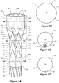
- Figure 5A One example of an endograft 10 according to the present disclosure is shown in Figure 5A.
- Figures 5B, 5C and 5D show lateral cross-sections of the endograft of Figure 5A through section lines 5B-5B, 5C-5C and 5D-5D respectively.
- the endograft 10 consists generally of in the form of a tubular stent graft having a proximal end portion 12 and a distal end portion 14, a tubular body 15, and a lumen 16 extending therethrough.
- the endograft 10 may be configured to receive a fluid flow in a proximal to distal direction.
- the endograft 10 may be any suitable length.
- the endograft 10 is a suitable length corresponding to the length of a lesion site where the endograft 10 is to be positioned.
- the endograft 10 may be in a compressed or collapsed configuration (not shown) or a radially expanded configuration (shown in Figure 5A ). In the expanded configuration the endograft 10 may apply a radially outward force upon at least a portion of a vessel, duct, or lumen e.g., to maintain patency within a passageway.
- the endograft 10 may be any suitable selected diameter and may be constructed of any biocompatible graft material 20 which is suitable for facilitating repair of an injured or diseased body vessel.
- the graft material 20 may be synthetic and/or naturally-derived material. Synthetic biocompatible polymers may include but are not limited to polyethylene terephthalate, polyurethane, nylon, polyester, high molecular weight polyethylene (such as Thoralon), polytetrafluoroethylene, or combinations thereof.
- the graft material 20 can be porous or non-porous and also may be impregnated or coated with one or more therapeutic substances. In one example, the graft material may be constructed of the commercially available material referred to as Dacron.
- the graft material may consist of small-intestine submucosa ("SIS") material, which may be obtained from porcine intestine.
- SIS small-intestine submucosa
- the graft material should have sufficient flexibility to allow for navigation of the vasculature and delivery to a targeted area in the body.
- the graft material 20 is a low profile material or an ultralow profile material.
- the endograft 10 may be supported by one or more stents 21 along its length.
- One or more stents 21 may be located on an interior surface 23, exterior surface 25, or both, of the tubular body 15 of the endograft 10.
- the number of stents and their placement can be varied to suit the particular application or patient anatomy.
- the endograft 10 may be unsupported along its length such that there are no body stents located on the graft material between the proximal end portion 12 and distal end portion 14 of the endograft 10.
- stent 21 may be a Z-stent.
- stent 21 may have a distal end 30 with a series of distal apices 31 and a proximal end 39 with a series of proximal apices 33.
- Stent 21 may also have one or more elongate struts 35 connecting the distal apices 31 to the proximal apices 33.
- Suitable stents 21 for use in connection with the endograft 10 described herein may be self-expanding or mechanically-expandable stents or both, and may be deployed according to conventional methodology.
- a self-expanding stent may be manufactured from a shape-memory alloy, such as nickel titanium alloy (Nitinol). If the stent comprises a self-expanding material such as Nitinol, the stent may be heat-set into the desired expanded state whereby the stent can assume a relaxed radially expanded configuration.
- the stent may be made from other metals and alloys that allow the stent to return to its original expanded configuration upon deployment, such as, for example, stainless steel, cobalt-chrome alloys, amorphous metals, and/or non-metallic materials as would be recognized by one of skill in the art.
- the endograft 10 may be mechanically expanded, such as through the use of an expandable balloon placed within the lumen 16 of the endograft 10 and then radially outwardly expanded.
- a plurality of zig zag stents 21 include a proximal end internal stent 13 and a distal end internal stent 27. Between stents 13 and 27 they may be three external stents 22, 24, 26.
- the endograft 10 may be anchored to an interior wall of a body vessel, duct, or lumen proximally and/or distally to a lesion site.
- the endograft 10 of Figure 5A has a proximal end sealing region 11 and a distal end sealing region 29.
- the distal sealing region 29 of the endograft 10 of Figure 5A may include an uncovered distal stent 28. This distal stent 28 may include barbs (not shown) to anchor the endograft 10 in place.
- the tubular body 15 of the endograft 10 may have a tubular wall 17 extending from the proximal end portion 12 to the distal end portion 14 of the endograft 10.
- the diameter of the tubular body 15 may change along the length of the endograft 10. In one example, the diameter at the proximal end portion 12 of the tubular body 15 is greater than the diameter at the distal end portion 14 of the tubular body 15.
- a tapered transition portion 45 may connect the proximal end portion 12 and the distal end portion 14.
- the tubular body 15 may have one or more lumens extending therethrough.
- the tubular body 15 comprises the main lumen 16 extending longitudinally from the proximal end portion 12 to the distal end portion 14 of the endograft 10.
- the endograft 10 may include an internal branch portion 37.
- the internal branch portion 37 extends from a recess or opening 250 in the tubular wall 17 into the main lumen 16 of the tubular body 15.
- the branch portion 37 may have a proximal end 52, and distal end 54 and a lumen 36 extending therethrough.
- the proximal end 52 has a larger diameter than the distal end 54 of the branch portion 37.
- the branch portion 37 may be constructed from the same biocompatible material as the graft material 20.
- Figures 5B, 5C, and 5D show the endograft 10 at the proximal lateral 100, intermediate lateral 200 and distal lateral 300 cross-sections, respectively. These lateral cross-sections can be identified as section lines 5B-5B, 5C-5C and 5D-5D marked on Figure 5A respectively.
- the tubular wall has the main lumen 16 extending therethrough at the proximal lateral portion 100 of the endograft 10.
- the main lumen 16 and the lumen 36 of the internal branch portion 37 extend through the tubular body 15.
- Figure 5C also shows a seam 40 in the graft material 20 which will be described in greater detail below.
- the distal lateral 300 cross-section Figure 5D
- the main lumen 16 extends through the endograft 10.
- one method of constructing the endograft 10 shown in Figure 5A will now be described with reference to Figures 1-4 .
- one novel feature of the disclosed endograft 10 is that the internal branch portion 37 is constructed using the excess of the graft material 20 used to make the tubular body 15, thus eliminating or reducing the need to sew a separate branch to the graft material.
- Figure 1 is a plan view of a flattened tube of biocompatible material with a 12 o'clock line down its centre.
- Figure 2 is a similar view to that of Figure 1 but shows the 12 o'clock line on the right hand lateral edge of the tube.
- tubular wall 17 of the endograft 10 is shown in a flattened condition so as to form two parallel spaced-apart folds that define tubular wall portion 18 and tubular wall portion 19.
- a 12 o'clock line 450 is marked on the graft material 20.
- lines 410 and 420 are marked on the graft material 20. Lines 410 and 420 may represent a portion of the outline of the internal branch portion 37. The line 420 indicates the position that will become the recess or opening 250 and the exit 34 from the branch lumen 36.
- Figure 2 shows the graft material 20 folded at the 6 and 9 o'clock position aligning the lines 410 with each other.
- the flattened graft material may be partitioned by sewing the seam 40 along the internal branch lines 410.
- the seam 40 may attach two portions of the graft material 20 together along line 410.
- the seam 40 may be sewn using any suitable method and may be sewn using any suitable biocompatible material.
- an excess portion 15' of graft material 20 may be cut out and discarded.
- a longitudinal cut may occur near the seam 40 at longitudinal edges 214 and 216. Two adjacent longitudinal edges 214 and 216 may join each other along the seam 40. A latitudinal cut may occur at lateral edge 218.
- the graft material 20 may be sealed my any means along one or more cut lines. In one example (shown in Fig. 3b ), the graft material 20 is heat sealed along longitudinal edges 214 and 216 as described below.
- the seam 40 may extend from the distal end portion 30 of the endograft 10 to a point proximal to the lateral edge 218.
- the branch portion 37 may be formed in the tubular wall 17 area between the seam 40 and the 12 o'clock line 450.
- the branch portion 37 may have a mouth 38 and an exit 34 that connects the branch portion 37 to the tubular body 15.
- Figures 3A and 3B show end views of the flattened tube of Figure 2 after the seam 40 has been sewn and a portion 15' of the graft material 20 has been cut out and discarded.
- Figure 3A is an end view of the tube of Figure 2 after a longitudinally extending portion from the tubular wall has been cut out.
- Figure 3B is a similar view to Figure 3A but shows the tube after edges 214 and 218 formed from a cut have been heat sealed.
- the tubular wall portions 18 and 19 are sewn together to form the seam 40.
- Adjacent longitudinal edges 214 and 216 join each other at the lateral edge 218. All of the edges 214, 216 and 218 are formed when the excess graft material 15' is cut and discarded. This leaves the lateral edge 218 and the mouth 38 of the internal branch portion 37.
- Figure 4A is an isometric view showing the tube of Figure 3B .
- the graft material 20 is no longer in a flattened configuration, but rather in a tubular configuration.
- the seam 40 occurs along the graft material 20 along line 410 and the excess graft material has been cut away.
- the mouth 38 to the internal branch portion 37 is illustrated in Figure 4A .
- Figures 4B, 4C and 4D are proximal lateral, intermediate lateral and distal lateral cross-sections through the tube shown in Figure 4A through section lines 4B-4B, 4C-4C and 4D-4D respectively.
- the graft material forms the tubular wall 17 with main lumen 16.
- Figure 4C illustrates addition of the branch portion 37 having lumen 36.
- Figure 4C also shows the seam 40 in the tubular wall 17.
- the tubular wall 17 and the seam 40 are illustrated.
- FIG. 8 is an isometric view of a space frame.
- Figure 9 is an isometric view showing the space frame of Figure 8 attached to the internal branch portion 37 shown in Figure 4A .
- the branch portion 37 may have a space frame 41.
- the space frame 41 may have an entrance reinforcing ring 43 and an exit reinforcing ring 47.
- the entrance and exit reinforcing rings 43,47 may be spaced apart axially by one or more struts 44 and 48.
- the space frame 41 comprises an assembly of two individual ring and strut components 42, 46.
- Each ring and strut component 42, 46 may comprise a circular ring portion defining a plane of the circular ring portion and a strut extending at right angles to the plane of the circular ring portion from a periphery of the circular ring portion.
- One of the two circular rings may form the entrance reinforcing ring 43 and the other of the two circular rings may form the exit reinforcing ring 47.
- ring and strut component 42 may comprise the entrance reinforcing ring 43 and the strut 44.
- Ring and strut component 46 may comprise the exit reinforcing ring 47 and strut 48.
- the space frame 41 may be attached to the branch portion 37 in any suitable way.
- space frame 41 is sewn into the branch portion 37 with stitching 49.
- the mouth 38 of the branch portion 37 may be biased towards an open condition by the entrance reinforcing ring 43.
- the exit reinforcing ring 47 may bias the exit 34 (shown Figure 6 ) into an open condition. This open condition is also apparent in the isometric view of Figure 7 looking down into the endograft 10 from its proximal end 12.
- the space frame 41 may be constructed with any biocompatible material.
- the space frame 41 comprises super-elastic wire, such as Nitinol. Other suitable materials may be used.
- tubular body 15 graft material 20 shown in Figures 1-4 and 8-9 may be everted or turned inside out so that the branch portion 37 sits internally in the tubular body 15, as shown in the endograft 10 shown in Figures 5 -7 and 10-11 .
- Figures 5A-D show one example of an endograft 10 after it has been constructed according to the disclosure above.
- stents 13, 22, 24, 26, 28, and 29 may be attached to the tubular wall 17 by any known method including using adhesives and stitching.
- the shape of the branch portion 37 may further be changed as desired.
- the branch portion 37 may be further cut and heat sealed to any desirable shape.
- excess tubular wall material may be cut out and the resultant slits may be sewn to form seams 272 and 274. In other words, the excess material may be gathered and trimmed to create a V-shape (as shown in Figure 5A ).
- the recess or opening 250 in the tubular wall 17 may open into the exit 34 of the branch portion 37.
- the recess or opening 250 may be at least partially disposed within a V-shaped region 260 formed between two adjacent struts 22a, 22b and a bend 22c of zig zag stent 22, that stent 22 being one of the plurality of zig zag stents 21 as is shown most clearly in Figure 5A .
- the tubular wall 17 of the main lumen may have at least one seam 40 adjacent to the V-shaped region 260 formed between two adjacent struts and a bend of one of the plurality of zig zag stents 21.
- the tubular body 15 of the endograft 10 and in embodiments also the main lumen may include a proximal portion 100, an intermediate portion 200 and a distal portion 300.
- the tubular body 15 of the endograft 10 may have the seam 40 extending longitudinally along a portion of the tubular wall 17.
- the seam 40 may extend longitudinally beside both the branch lumen and the distal portion of the main lumen.
- Figures 5B, 5C and 5D show lateral cross-sections of the endograft of Figure 5A through section lines 5B-5B, 5C-5C and 5D-5D respectively.
- the tubular wall 17 has the main lumen 16.
- the intermediate portion 200 shown in Figure 5C
- the internal branch portion 37 and the branch lumen 38 may be within the main lumen 16.
- the seam 40 may be created where the tubular wall 17 is pinched together to form the branch portion 37.
- the distal end 14 of the endograft can be seen as well as the seam 40 formed where the tubular wall 17 is stitched after the excess graft material has been cut out and discarded.
- Figure 6 is a longitudinal cross-sectional view of the endograft of Figure 5A .
- Figure 7 is an isometric view looking into the endograft of Figures 5A and 6 from its proximal end.
- the internal branch portion 37 can be seen internal to the tubular body 15. With this cross-sectional view, the external stents 22,24,26 and the wires of the space frame 41 are not shown (the space frame 41 is shown in Figure 8 and is described below).
- the branch portion 37 comprises an entrance 32 into the main lumen 16 within the intermediate portion 200 of tubular body 15.
- the branch portion 37 may have an exit 34 through the tubular wall 17 of the tubular body 15.
- the exit 34 through the tubular wall of the main lumen 16 may open into the recess or opening 250.
- the lumen 36 may run between the entrance 32 and the exit 34.
- FIG. 7 is an isometric view looking down into the endograft 10 from its proximal end 12, the branch portion 37 can be seen within the main lumen 16.
- the proximal end of the branch portion 37 may have a larger diameter than the distal end of the branch portion 37.
- the deployment of one embodiment of the endograft 10 can occur in any vessel, duct, or lumen.
- the endograft 10 may be deployed in a patient using any known technique or method.
- the deployment device is the device disclosed in U.S. Pat. No. 7537606 titled Branch stent graft deployment and method, which is herewith incorporated in its entirety into this specification.
- endograft 10 can be deployed into the thoracic arch of a patient.
- Figure 10A is a diagrammatic view of the endograft of Figures 5A , 6 and 7 within the anatomy of a patient.
- Figure 10B is a similar view to that of Figure 10A but also shows a side branch endograft.
- the thoracic arch region of a patient generally comprises an ascending aorta 502 extending from an aortic valve 550 of the heart of the patient, then over the thoracic arch to the descending aorta 522. From the thoracic arch, three main arteries extend. These are the innominate artery, the left carotid artery 520 and a subclavian artery 510.
- This embodiment of the disclosure will generally be discussed with reference to deployment of an endograft 10 in the form of a stent graft 10 with a side branch into the aorta 500 and left subclavian artery 510 but the disclosure is not so restricted.
- the endograft 10 may be necessary in the aortic arch region when an aneurysm in the aorta 500 extends up the aorta 500 to such an extent that there is insufficient patent aortic wall to provide good sealing for a stent graft 10 distally of the left subclavian artery 510 (for instance, see aneurysmal portion 505 in Figure 10A ). It is desirable in such circumstances to extend the stent graft 10 to seal onto good artery wall at least between the left carotid artery 520 and the left subclavian artery 510.
- the proximal end sealing region 11 is shown in Figures 10A and 10B sealing onto good artery wall at least between the left carotid artery 520 and the left subclavian artery 510.
- the distal end sealing region 29 is also shown in Figures 10A and 10B sealing onto good artery wall along the descending aorta 522 below the aneurysmal portion 505.
- FIGs 10A shows a detailed view of the deployed stent graft 10, as shown in Figure 5A , into a thoracic arch of a patient.
- a separate balloon expandable, or self expanding, side arm or side branch endograft 60 such as stent graft 60 can then be deployed brachially through the subclavian artery 510 so that its upstream or proximal end enters the branch lumen 36 and then it can be allowed to expand, or be balloon expanded, so that the proximal end is expanded within the branch portion 37 to seal the side branch stent graft 60 into the branch lumen 36 of the main stent graft 10, as is shown in Figure 10B .
- the recess or opening 250 may be adapted to accommodate a side arm, the side arm having an upstream end and a downstream end, the upstream end positionable within the branch lumen and the downstream end within a branch vessel. Again, this can be achieved as is described in the afore-mentioned U.S. Pat. No. 7537606 titled Branch stent graft deployment and method.
- FIG 11 is an isometric view of another endograft 10' according to the disclosure.
- the distal most stent 27' is an external stent. That is, the stent 27' is secured on the outside of the tubular body 15.
- This endograft 10' can be used as part of an interconnected stent graft assembly where a more distal stent graft seals to the inside of the distal end of the endograft 10'.
- Such an arrangement may be suitable for a patient who has an aneurysm that extends further down the descending aorta that the aneurysm 505 shown in Figures 10A and 10B .
- the above described method of producing the endograft 10 utilises excess graft material 20 to produce the branch portion 37. This eliminates the need to separately fabricate and attach the branch portion 37, reducing the complexity of the final endograft 10 or endograft 10', as illustrated in Figures 5A and 11 respectively.
- Embodiments of the disclosure will be used by vascular surgeons to treat aneurysms and to repair regions of the aorta, including, but not limited to, the aortic arch. Embodiments of the disclosure will be used in other parts of the vasculature system.
Landscapes
- Health & Medical Sciences (AREA)
- Gastroenterology & Hepatology (AREA)
- Pulmonology (AREA)
- Cardiology (AREA)
- Oral & Maxillofacial Surgery (AREA)
- Transplantation (AREA)
- Engineering & Computer Science (AREA)
- Biomedical Technology (AREA)
- Heart & Thoracic Surgery (AREA)
- Vascular Medicine (AREA)
- Life Sciences & Earth Sciences (AREA)
- Animal Behavior & Ethology (AREA)
- General Health & Medical Sciences (AREA)
- Public Health (AREA)
- Veterinary Medicine (AREA)
- Prostheses (AREA)
Abstract
Description
- The present disclosure relates generally to medical devices. Embodiments relate to endografts. Embodiments relate to endografts deployable into the vascular system of humans or animals.
- Endografts and delivery device assemblies for endografts are used in aortic intervention. They are used by vascular surgeons to treat aneurysms and to repair regions of the aorta, including the aortic arch, the thoracic aorta, the abdominal aorta and the aortic bifurcation.
- Multiple stent grafts may be implanted to provide a system of interconnected stent grafts. Interconnected stent grafts can be made of fenestrated stent grafts and smaller side branch grafts.
- Endografts for treating branched vessels, typically stent grafts, are intricate and take considerable time to produce.
- Throughout this specification, the term "distal" with respect to a portion of the aorta, a deployment device or an endograft means the end of the aorta, deployment device or endograft further away in the direction of blood flow from the heart and the term "proximal" means the portion of the aorta, deployment device or end of the endograft nearer to the heart in the direction of blood flow. When applied to other vessels, similar terms such as caudal and cranial should be understood.
- Aspects of the present invention seek to provide an improved endograft, for example for treating branched vessels. Aspects of the present invention seek to provide an improved method.
- According to an aspect of the invention, there is provided an endograft as in claim 1.
- According to an aspect of the invention, there is provided a method as in
claim 13. - According to an aspect of the invention, there is provided an endograft comprising a proximal end and a distal end, the endograft comprising a tube of biocompatible material, the tube comprising:
- a main lumen extending longitudinally from a proximal end to a distal end, the main lumen including a proximal portion, an intermediate portion and a distal portion;
- a branch lumen within the intermediate portion of the main lumen; and
- a seam, the seam extending longitudinally beside both the branch lumen and the distal portion of the main lumen,
- wherein the tube comprises a lateral cross-section defining a tubular wall, wherein a portion of the tubular wall is pinched together by a seam to form a branch portion.
- According to an aspect of the present disclosure, there is provided an endograft comprising a proximal end and a distal end, the endograft comprising a tube of biocompatible material, the tube comprising: a main lumen extending longitudinally from the proximal end to the distal end, the main lumen including a proximal portion, an intermediate portion and a distal portion; a branch lumen within the intermediate portion of the main lumen; and a seam, the seam extending longitudinally beside both the branch lumen and the distal portion of the main lumen, wherein the tube comprises a lateral cross-section defining a tubular wall pinched together by the seam to form a branch portion.
- According to an aspect of the present invention, there is provided a method of producing a endograft comprising the steps of: providing a tube of biocompatible material, the tube having a tubular wall; flattening the tube so that the tubular wall forms two substantially planar wall portions; partitioning the flattened tube by creating a longitudinal seam between the two wall portions; cutting a piece out of the tube from a position adjacent to the longitudinal seam so as to create a branch mouth into the tube; attaching a super-elastic ring to the branch mouth; and everting the tube.
- Embodiments of the present disclosure are described below, by way of example only, with reference to the accompanying drawings wherein:
-
Figure 1 is a plan view of a flattened tube of biocompatible material with a 12 o'clock line down its centre; -
Figure 2 is a similar view to that ofFigure 1 but shows the 12 o'clock line on the right hand lateral edge of the tube; -
Figure 3A is an end view of the tube ofFigure 2 after a longitudinally extending portion from the tubular wall has been cut out; -
Figure 3B is similar view toFigure 3A but shows the tube after edges formed from a cut have been sealed; -
Figure 4A is an isometric view showing the tube ofFigure 3 ; -
Figures 4B, 4C and 4D are proximal lateral, intermediate lateral and distal lateral cross-sections through the tube shown inFigure 4A throughsection lines 4B-4B, 4C-4C and 4D-4D respectively; -
Figure 5A shows an endograft according to the disclosure is an isometric view; -
Figures 5B, 5C and 5D show lateral cross-sections of the endograft ofFigure 5A throughsection lines 5B-5B, 5C-5C and 5D-5D respectively; -
Figure 6 is a longitudinal cross-sectional view of the endograft ofFigure 5A ; -
Figure 7 is an isometric view looking into the endograft ofFigures 5A and6 from its proximal end; -
Figure 8 is an isometric view of a space frame; -
Figure 9 is an isometric view showing the space frame ofFigure 8 attached to a portion of the endograft ofFigure 4A ; -
Figure 10A is a diagrammatic view of the endograft ofFigures 5A ,6 and7 within the anatomy of a patient; -
Figure 10B is a similar view to that ofFigure 10A but also shows a side branch endograft; and -
Figure 11 is an isometric view of another endograft according to the disclosure. - One example of an
endograft 10 according to the present disclosure is shown inFigure 5A. Figures 5B, 5C and 5D show lateral cross-sections of the endograft ofFigure 5A throughsection lines 5B-5B, 5C-5C and 5D-5D respectively. - Referring to
Figure 5A , it can be seen that theendograft 10 consists generally of in the form of a tubular stent graft having aproximal end portion 12 and adistal end portion 14, atubular body 15, and alumen 16 extending therethrough. Theendograft 10 may be configured to receive a fluid flow in a proximal to distal direction. - The
endograft 10 may be any suitable length. In one example, theendograft 10 is a suitable length corresponding to the length of a lesion site where theendograft 10 is to be positioned. - The
endograft 10 may be in a compressed or collapsed configuration (not shown) or a radially expanded configuration (shown inFigure 5A ). In the expanded configuration theendograft 10 may apply a radially outward force upon at least a portion of a vessel, duct, or lumen e.g., to maintain patency within a passageway. - The
endograft 10 may be any suitable selected diameter and may be constructed of anybiocompatible graft material 20 which is suitable for facilitating repair of an injured or diseased body vessel. Thegraft material 20 may be synthetic and/or naturally-derived material. Synthetic biocompatible polymers may include but are not limited to polyethylene terephthalate, polyurethane, nylon, polyester, high molecular weight polyethylene (such as Thoralon), polytetrafluoroethylene, or combinations thereof. Thegraft material 20 can be porous or non-porous and also may be impregnated or coated with one or more therapeutic substances. In one example, the graft material may be constructed of the commercially available material referred to as Dacron. In another example the graft material may consist of small-intestine submucosa ("SIS") material, which may be obtained from porcine intestine. The graft material should have sufficient flexibility to allow for navigation of the vasculature and delivery to a targeted area in the body. Preferably, thegraft material 20 is a low profile material or an ultralow profile material. - The
endograft 10 may be supported by one ormore stents 21 along its length. One ormore stents 21 may be located on aninterior surface 23,exterior surface 25, or both, of thetubular body 15 of theendograft 10. The number of stents and their placement (internal or external) can be varied to suit the particular application or patient anatomy. Alternatively, theendograft 10 may be unsupported along its length such that there are no body stents located on the graft material between theproximal end portion 12 anddistal end portion 14 of theendograft 10. - In one example,
stent 21 may be a Z-stent. For example,stent 21 may have adistal end 30 with a series ofdistal apices 31 and aproximal end 39 with a series ofproximal apices 33.Stent 21 may also have one or moreelongate struts 35 connecting thedistal apices 31 to theproximal apices 33. -
Suitable stents 21 for use in connection with theendograft 10 described herein may be self-expanding or mechanically-expandable stents or both, and may be deployed according to conventional methodology. A self-expanding stent may be manufactured from a shape-memory alloy, such as nickel titanium alloy (Nitinol). If the stent comprises a self-expanding material such as Nitinol, the stent may be heat-set into the desired expanded state whereby the stent can assume a relaxed radially expanded configuration. The stent may be made from other metals and alloys that allow the stent to return to its original expanded configuration upon deployment, such as, for example, stainless steel, cobalt-chrome alloys, amorphous metals, and/or non-metallic materials as would be recognized by one of skill in the art. Additionally or alternatively, theendograft 10 may be mechanically expanded, such as through the use of an expandable balloon placed within thelumen 16 of theendograft 10 and then radially outwardly expanded. - In the example shown in
Figure 5A , a plurality ofzig zag stents 21 include a proximal endinternal stent 13 and a distal endinternal stent 27. Betweenstents external stents - The
endograft 10 may be anchored to an interior wall of a body vessel, duct, or lumen proximally and/or distally to a lesion site. Theendograft 10 ofFigure 5A has a proximalend sealing region 11 and a distalend sealing region 29. For example, thedistal sealing region 29 of theendograft 10 ofFigure 5A may include an uncovereddistal stent 28. Thisdistal stent 28 may include barbs (not shown) to anchor theendograft 10 in place. - The
tubular body 15 of theendograft 10 may have atubular wall 17 extending from theproximal end portion 12 to thedistal end portion 14 of theendograft 10. The diameter of thetubular body 15 may change along the length of theendograft 10. In one example, the diameter at theproximal end portion 12 of thetubular body 15 is greater than the diameter at thedistal end portion 14 of thetubular body 15. A taperedtransition portion 45 may connect theproximal end portion 12 and thedistal end portion 14. - The
tubular body 15 may have one or more lumens extending therethrough. In one example, thetubular body 15 comprises themain lumen 16 extending longitudinally from theproximal end portion 12 to thedistal end portion 14 of theendograft 10. - The
endograft 10 may include aninternal branch portion 37. In one example, theinternal branch portion 37 extends from a recess or opening 250 in thetubular wall 17 into themain lumen 16 of thetubular body 15. Thebranch portion 37 may have aproximal end 52, anddistal end 54 and alumen 36 extending therethrough. In one example, theproximal end 52 has a larger diameter than thedistal end 54 of thebranch portion 37. Thebranch portion 37 may be constructed from the same biocompatible material as thegraft material 20. -
Figures 5B, 5C, and 5D show theendograft 10 at theproximal lateral 100,intermediate lateral 200 anddistal lateral 300 cross-sections, respectively. These lateral cross-sections can be identified as section lines 5B-5B, 5C-5C and 5D-5D marked onFigure 5A respectively. As shown inFigure 5B , the tubular wall has themain lumen 16 extending therethrough at the proximallateral portion 100 of theendograft 10. In theintermediate lateral 200 cross section (shown inFigure 5C ), themain lumen 16 and thelumen 36 of theinternal branch portion 37 extend through thetubular body 15.Figure 5C also shows aseam 40 in thegraft material 20 which will be described in greater detail below. In thedistal lateral 300 cross-section (Figure 5D ), themain lumen 16 extends through theendograft 10. - In order to better understand the structure and construction of the endograft shown in
Figures 5A to 5D , one method of constructing theendograft 10 shown inFigure 5A will now be described with reference toFigures 1-4 . In particular, one novel feature of the disclosedendograft 10 is that theinternal branch portion 37 is constructed using the excess of thegraft material 20 used to make thetubular body 15, thus eliminating or reducing the need to sew a separate branch to the graft material. -
Figure 1 is a plan view of a flattened tube of biocompatible material with a 12 o'clock line down its centre.Figure 2 is a similar view to that ofFigure 1 but shows the 12 o'clock line on the right hand lateral edge of the tube. - Referring to
Figure 1 , a tube of biocompatible material that may form thetubular body 15 is shown. In particular,tubular wall 17 of theendograft 10 is shown in a flattened condition so as to form two parallel spaced-apart folds that definetubular wall portion 18 andtubular wall portion 19. Referring toFigure 1 , a 12o'clock line 450 is marked on thegraft material 20.Further lines graft material 20.Lines internal branch portion 37. Theline 420 indicates the position that will become the recess oropening 250 and theexit 34 from thebranch lumen 36. -
Figure 2 shows thegraft material 20 folded at the 6 and 9 o'clock position aligning thelines 410 with each other. - As shown in
Figure 2 , the flattened graft material may be partitioned by sewing theseam 40 along theinternal branch lines 410. In other words, theseam 40 may attach two portions of thegraft material 20 together alongline 410. Theseam 40 may be sewn using any suitable method and may be sewn using any suitable biocompatible material. - After the
seam 40 is sewn, anexcess portion 15' ofgraft material 20 may be cut out and discarded. In one example, a longitudinal cut may occur near theseam 40 atlongitudinal edges longitudinal edges seam 40. A latitudinal cut may occur atlateral edge 218. - The
graft material 20 may be sealed my any means along one or more cut lines. In one example (shown inFig. 3b ), thegraft material 20 is heat sealed alonglongitudinal edges - The
seam 40 may extend from thedistal end portion 30 of theendograft 10 to a point proximal to thelateral edge 218. Thebranch portion 37 may be formed in thetubular wall 17 area between theseam 40 and the 12o'clock line 450. Thebranch portion 37 may have amouth 38 and anexit 34 that connects thebranch portion 37 to thetubular body 15. -
Figures 3A and 3B show end views of the flattened tube ofFigure 2 after theseam 40 has been sewn and aportion 15' of thegraft material 20 has been cut out and discarded. In particular,Figure 3A is an end view of the tube ofFigure 2 after a longitudinally extending portion from the tubular wall has been cut out.Figure 3B is a similar view toFigure 3A but shows the tube afteredges - As shown in
Figures 3A and 3B , thetubular wall portions seam 40. Adjacentlongitudinal edges lateral edge 218. All of theedges excess graft material 15' is cut and discarded. This leaves thelateral edge 218 and themouth 38 of theinternal branch portion 37. -
Figure 4A is an isometric view showing the tube ofFigure 3B . As shown inFigures 4A , thegraft material 20 is no longer in a flattened configuration, but rather in a tubular configuration. Theseam 40 occurs along thegraft material 20 alongline 410 and the excess graft material has been cut away. Themouth 38 to theinternal branch portion 37 is illustrated inFigure 4A . -
Figures 4B, 4C and 4D are proximal lateral, intermediate lateral and distal lateral cross-sections through the tube shown inFigure 4A throughsection lines 4B-4B, 4C-4C and 4D-4D respectively. As shown inFigure 4B , the graft material forms thetubular wall 17 withmain lumen 16. At the intermediate lateral cross-section,Figure 4C illustrates addition of thebranch portion 37 havinglumen 36.Figure 4C also shows theseam 40 in thetubular wall 17. At the distallateral cross section 4D-4D shown inFigure 4D , thetubular wall 17 and theseam 40 are illustrated. - It may be desirable to provide additional support to the
internal branch portion 37. In one example, a super-elastic ring of nitinol wire is attached to support thebranch portion 37. For example,space frame 41 may provide additional support to theinternal branch portion 37.Figure 8 is an isometric view of a space frame.Figure 9 is an isometric view showing the space frame ofFigure 8 attached to theinternal branch portion 37 shown inFigure 4A . - As shown in
Figures 8 and 9 , it can be seen that thebranch portion 37 may have aspace frame 41. Thespace frame 41 may have anentrance reinforcing ring 43 and anexit reinforcing ring 47. The entrance andexit reinforcing rings more struts space frame 41 comprises an assembly of two individual ring and strutcomponents strut component entrance reinforcing ring 43 and the other of the two circular rings may form theexit reinforcing ring 47. For instance, ring andstrut component 42 may comprise theentrance reinforcing ring 43 and thestrut 44. Ring andstrut component 46 may comprise theexit reinforcing ring 47 andstrut 48. - As shown in
Figure 9 , thespace frame 41 may be attached to thebranch portion 37 in any suitable way. In one example,space frame 41 is sewn into thebranch portion 37 withstitching 49. Themouth 38 of thebranch portion 37 may be biased towards an open condition by theentrance reinforcing ring 43. Similarly, theexit reinforcing ring 47 may bias the exit 34 (shownFigure 6 ) into an open condition. This open condition is also apparent in the isometric view ofFigure 7 looking down into theendograft 10 from itsproximal end 12. - The
space frame 41 may be constructed with any biocompatible material. In one example, thespace frame 41 comprises super-elastic wire, such as Nitinol. Other suitable materials may be used. - The
tubular body 15graft material 20 shown inFigures 1-4 and8-9 may be everted or turned inside out so that thebranch portion 37 sits internally in thetubular body 15, as shown in theendograft 10 shown inFigures 5 -7 and10-11 .Figures 5A-D show one example of anendograft 10 after it has been constructed according to the disclosure above. - Returning to
Figures 5A-D , once thetubular body 15graft material 20 is turned inside out,stents tubular wall 17 by any known method including using adhesives and stitching. Once thebranch portion 37 is located internally in the tubular body, the shape of thebranch portion 37 may further be changed as desired. For example, thebranch portion 37 may be further cut and heat sealed to any desirable shape. In one example, excess tubular wall material may be cut out and the resultant slits may be sewn to formseams Figure 5A ). - As shown in
Figure 5A , the recess or opening 250 in thetubular wall 17 may open into theexit 34 of thebranch portion 37. The recess oropening 250 may be at least partially disposed within a V-shapedregion 260 formed between twoadjacent struts bend 22c ofzig zag stent 22, thatstent 22 being one of the plurality ofzig zag stents 21 as is shown most clearly inFigure 5A . In one example, thetubular wall 17 of the main lumen may have at least oneseam 40 adjacent to the V-shapedregion 260 formed between two adjacent struts and a bend of one of the plurality ofzig zag stents 21. - As shown in
Figure 5A , thetubular body 15 of theendograft 10 and in embodiments also the main lumen may include aproximal portion 100, anintermediate portion 200 and adistal portion 300. Thetubular body 15 of theendograft 10 may have theseam 40 extending longitudinally along a portion of thetubular wall 17. Theseam 40 may extend longitudinally beside both the branch lumen and the distal portion of the main lumen. -
Figures 5B, 5C and 5D show lateral cross-sections of the endograft ofFigure 5A throughsection lines 5B-5B, 5C-5C and 5D-5D respectively. In the proximal portion (shown inFigure 5B ), thetubular wall 17 has themain lumen 16. In the intermediate portion 200 (shown inFigure 5C ) theinternal branch portion 37 and thebranch lumen 38 may be within themain lumen 16. Referring again toFigures 5A, 5B, 5C, 5D and6 , it can be seen that theseam 40 may be created where thetubular wall 17 is pinched together to form thebranch portion 37. In the distal portion (shown inFigure 5D ), thedistal end 14 of the endograft can be seen as well as theseam 40 formed where thetubular wall 17 is stitched after the excess graft material has been cut out and discarded. -
Figure 6 is a longitudinal cross-sectional view of the endograft ofFigure 5A .Figure 7 is an isometric view looking into the endograft ofFigures 5A and6 from its proximal end. - Referring to the longitudinal cross-sectional view of
Figure 6 , theinternal branch portion 37 can be seen internal to thetubular body 15. With this cross-sectional view, theexternal stents space frame 41 are not shown (thespace frame 41 is shown inFigure 8 and is described below). - The
branch portion 37 comprises anentrance 32 into themain lumen 16 within theintermediate portion 200 oftubular body 15. Thebranch portion 37 may have anexit 34 through thetubular wall 17 of thetubular body 15. Theexit 34 through the tubular wall of themain lumen 16 may open into the recess oropening 250. Thelumen 36 may run between theentrance 32 and theexit 34. - Referring now to
Figure 7 , which is an isometric view looking down into theendograft 10 from itsproximal end 12, thebranch portion 37 can be seen within themain lumen 16. The proximal end of thebranch portion 37 may have a larger diameter than the distal end of thebranch portion 37. - The deployment of one embodiment of the
endograft 10 can occur in any vessel, duct, or lumen. Theendograft 10 may be deployed in a patient using any known technique or method. In one example, the deployment device is the device disclosed inU.S. Pat. No. 7537606 titled Branch stent graft deployment and method, which is herewith incorporated in its entirety into this specification. - In one example, endograft 10 can be deployed into the thoracic arch of a patient.
Figure 10A is a diagrammatic view of the endograft ofFigures 5A ,6 and7 within the anatomy of a patient.Figure 10B is a similar view to that ofFigure 10A but also shows a side branch endograft. - The thoracic arch region of a patient generally comprises an ascending
aorta 502 extending from anaortic valve 550 of the heart of the patient, then over the thoracic arch to the descendingaorta 522. From the thoracic arch, three main arteries extend. These are the innominate artery, the leftcarotid artery 520 and asubclavian artery 510. This embodiment of the disclosure will generally be discussed with reference to deployment of anendograft 10 in the form of astent graft 10 with a side branch into theaorta 500 and leftsubclavian artery 510 but the disclosure is not so restricted. - The
endograft 10 may be necessary in the aortic arch region when an aneurysm in theaorta 500 extends up theaorta 500 to such an extent that there is insufficient patent aortic wall to provide good sealing for astent graft 10 distally of the left subclavian artery 510 (for instance, seeaneurysmal portion 505 inFigure 10A ). It is desirable in such circumstances to extend thestent graft 10 to seal onto good artery wall at least between the leftcarotid artery 520 and the leftsubclavian artery 510. - The proximal
end sealing region 11 is shown inFigures 10A and10B sealing onto good artery wall at least between the leftcarotid artery 520 and the leftsubclavian artery 510. The distalend sealing region 29 is also shown inFigures 10A and10B sealing onto good artery wall along the descendingaorta 522 below theaneurysmal portion 505. -
Figures 10A shows a detailed view of the deployedstent graft 10, as shown inFigure 5A , into a thoracic arch of a patient. A separate balloon expandable, or self expanding, side arm orside branch endograft 60 such asstent graft 60 can then be deployed brachially through thesubclavian artery 510 so that its upstream or proximal end enters thebranch lumen 36 and then it can be allowed to expand, or be balloon expanded, so that the proximal end is expanded within thebranch portion 37 to seal the sidebranch stent graft 60 into thebranch lumen 36 of themain stent graft 10, as is shown inFigure 10B . In other words, the recess oropening 250 may be adapted to accommodate a side arm, the side arm having an upstream end and a downstream end, the upstream end positionable within the branch lumen and the downstream end within a branch vessel. Again, this can be achieved as is described in the afore-mentionedU.S. Pat. No. 7537606 titled Branch stent graft deployment and method. -
Figure 11 is an isometric view of anotherendograft 10' according to the disclosure. With this embodiment, the distalmost stent 27' is an external stent. That is, thestent 27' is secured on the outside of thetubular body 15. Thisendograft 10' can be used as part of an interconnected stent graft assembly where a more distal stent graft seals to the inside of the distal end of theendograft 10'. Such an arrangement may be suitable for a patient who has an aneurysm that extends further down the descending aorta that theaneurysm 505 shown inFigures 10A and10B . - The above described method of producing the
endograft 10 utilisesexcess graft material 20 to produce thebranch portion 37. This eliminates the need to separately fabricate and attach thebranch portion 37, reducing the complexity of thefinal endograft 10 orendograft 10', as illustrated inFigures 5A and11 respectively. - The disclosure is not limited to this particular application but is discussed in relation to this particular application as an example.
- Embodiments of the disclosure will be used by vascular surgeons to treat aneurysms and to repair regions of the aorta, including, but not limited to, the aortic arch. Embodiments of the disclosure will be used in other parts of the vasculature system.
- Throughout the specification and the claims that follow, unless the context requires otherwise, the words "comprise" and "include" and variations such as "comprising" and "including" will be understood to imply the inclusion of a stated integer or group of integers, but not the exclusion of any other integer or group of integers.
- The reference to any prior art in this specification is not, and should not be taken as, an acknowledgement of any form of suggestion that such prior art forms part of the common general knowledge.
- It will be appreciated by those skilled in the art that the disclosure is not restricted in its use to the particular application described. Neither is the present disclosure restricted in its preferred embodiment with regard to the particular elements and/or features described or depicted herein. It will be appreciated that the disclosure is not limited to the embodiment or embodiments disclosed, but is capable of numerous rearrangements, modifications and substitutions without departing from the scope of the disclosure as set forth and defined by the following claims.
- All optional and preferred features and modifications of the described embodiments and dependent claims are usable in all aspects of the invention taught herein. Furthermore, the individual features of the dependent claims, as well as all optional and preferred features and modifications of the described embodiments are combinable and interchangeable with one another.
- The disclosures in United States
patent application number 15/228,438 AU2016210717
Claims (15)
- An endograft comprising a proximal end and a distal end, the endograft comprising a tube of biocompatible material, the tube comprising:a main lumen extending longitudinally from a proximal end to a distal end, the main lumen including a proximal portion, an intermediate portion and a distal portion;a branch lumen within the intermediate portion of the main lumen; anda seam, the seam extending longitudinally beside both the branch lumen and the distal portion of the main lumen,wherein the tube comprises a lateral cross-section defining a tubular wall, wherein a portion of the tubular wall is pinched together by the seam to form a branch portion.
- The endograft as claimed in claim 1 wherein the branch portion comprises an entrance within the intermediate portion of the main lumen and an exit through the tubular wall of the main lumen.
- The endograft as claimed in claim 2 comprising a recess, wherein the exit through the tubular wall of the main lumen opens into the recess.
- The endograft as claimed in claim 3 wherein the tube is supported by a plurality of zig zag stents, each of the stents comprising a plurality of struts and bends, the bends being between adjacent struts,
wherein the recess is at least partly disposed within a V-shaped region formed between two adjacent struts and a bend of one of the plurality of zig zag stents. - The endograft as claimed in claim 4 wherein the tubular wall of the main lumen comprises at least one seam adjacent the V-shaped region formed between two adjacent struts and a bend of one of the plurality of zig zag stents.
- The endograft as claimed in any of claims 3 to 5 wherein the recess is adapted to accommodate a side arm, the side arm having an upstream end configured to be positioned and a downstream end, the upstream end positionable within the branch lumen and the downstream end configured to be positioned within a branch vessel.
- The endograft as claimed in any preceding claim wherein the branch portion comprises an entrance reinforcing ring.
- The endograft as claimed in any preceding claim wherein the branch portion comprises an exit reinforcing ring.
- The endograft as claimed in any preceding claim wherein the branch portion comprises a reinforcement in the form of a space frame, the space frame formed by entrance and exit reinforcing rings spaced apart axially by at least one strut.
- The endograft as claimed in claim 9 wherein the space frame comprises an assembly of two individual ring and strut components, each ring and strut component comprising a circular ring portion defining a plane of the circular ring portion and a strut extending at right angles to the plane of the circular ring portion from a periphery of the circular ring portion,
whereby one of the two circular rings forms the entrance reinforcing ring and the other of the two circular rings forms the exit reinforcing ring. - The endograft as claimed in claim 9 or 10 wherein the space frame comprises super-elastic wire.
- The endograft as claimed in claim 11 wherein the super-elastic wire of the space frame comprises nitinol.
- A method of producing a endograft comprising the steps of:providing a tube of biocompatible material, the tube having a tubular wall;flattening the tube so that the tubular wall forms two substantially planar wall portions;partitioning the flattened tube by creating a longitudinal seam between the two wall portions;cutting a piece out of the tube from a position adjacent to the longitudinal seam so as to create a branch mouth into the tube;attaching a super-elastic ring to the branch mouth; andeverting the tube.
- The method of claim 13, wherein the method comprises the steps of:attaching a plurality of zig zag stents to the tubular wall; and/orwherein the partitioning step comprises the step of:sewing along the seam.
- The method of claim 13 or 14, wherein the cutting step creates excess material terminating in edges, and wherein the method includes the step of sealing the excess material.
Applications Claiming Priority (2)
| Application Number | Priority Date | Filing Date | Title |
|---|---|---|---|
| AU2016210717A AU2016210717B1 (en) | 2016-08-04 | 2016-08-04 | An endograft for treating branched vessels |
| US15/228,438 US10716660B2 (en) | 2016-08-04 | 2016-08-04 | Endograft for treating branched vessels |
Publications (2)
| Publication Number | Publication Date |
|---|---|
| EP3278767A1 true EP3278767A1 (en) | 2018-02-07 |
| EP3278767B1 EP3278767B1 (en) | 2024-02-28 |
Family
ID=59558343
Family Applications (1)
| Application Number | Title | Priority Date | Filing Date |
|---|---|---|---|
| EP17275120.8A Active EP3278767B1 (en) | 2016-08-04 | 2017-08-03 | An endograft for treating branched vessels |
Country Status (1)
| Country | Link |
|---|---|
| EP (1) | EP3278767B1 (en) |
Cited By (1)
| Publication number | Priority date | Publication date | Assignee | Title |
|---|---|---|---|---|
| WO2021129298A1 (en) * | 2019-12-27 | 2021-07-01 | 深圳市先健畅通医疗有限公司 | Luminal stent |
Citations (6)
| Publication number | Priority date | Publication date | Assignee | Title |
|---|---|---|---|---|
| WO2003082153A2 (en) * | 2002-03-25 | 2003-10-09 | Cook Incorporated | Branched vessel prothesis |
| US6645242B1 (en) * | 2000-12-11 | 2003-11-11 | Stephen F. Quinn | Bifurcated side-access intravascular stent graft |
| WO2006065644A1 (en) * | 2004-12-17 | 2006-06-22 | William A. Cook Australia Pty. Ltd. | Stented side branch graft |
| US7537606B2 (en) | 2003-04-03 | 2009-05-26 | Cook Incorporated | Branch stent graft deployment and method |
| US20110276062A1 (en) * | 2001-11-28 | 2011-11-10 | Aptus Endosystems, Inc. | Devices, systems, and methods for prosthesis delivery and implantation, including the use of a fastener tool |
| EP2547287A1 (en) * | 2010-03-19 | 2013-01-23 | William A. Cook Australia Pty. Ltd. | Thoracic stent graft |
Family Cites Families (2)
| Publication number | Priority date | Publication date | Assignee | Title |
|---|---|---|---|---|
| US6929661B2 (en) * | 2001-11-28 | 2005-08-16 | Aptus Endosystems, Inc. | Multi-lumen prosthesis systems and methods |
| US10660770B2 (en) * | 2017-07-18 | 2020-05-26 | Cook Medical Technologies Llc | Method of making an internal bidirectional branch |
-
2017
- 2017-08-03 EP EP17275120.8A patent/EP3278767B1/en active Active
Patent Citations (6)
| Publication number | Priority date | Publication date | Assignee | Title |
|---|---|---|---|---|
| US6645242B1 (en) * | 2000-12-11 | 2003-11-11 | Stephen F. Quinn | Bifurcated side-access intravascular stent graft |
| US20110276062A1 (en) * | 2001-11-28 | 2011-11-10 | Aptus Endosystems, Inc. | Devices, systems, and methods for prosthesis delivery and implantation, including the use of a fastener tool |
| WO2003082153A2 (en) * | 2002-03-25 | 2003-10-09 | Cook Incorporated | Branched vessel prothesis |
| US7537606B2 (en) | 2003-04-03 | 2009-05-26 | Cook Incorporated | Branch stent graft deployment and method |
| WO2006065644A1 (en) * | 2004-12-17 | 2006-06-22 | William A. Cook Australia Pty. Ltd. | Stented side branch graft |
| EP2547287A1 (en) * | 2010-03-19 | 2013-01-23 | William A. Cook Australia Pty. Ltd. | Thoracic stent graft |
Cited By (1)
| Publication number | Priority date | Publication date | Assignee | Title |
|---|---|---|---|---|
| WO2021129298A1 (en) * | 2019-12-27 | 2021-07-01 | 深圳市先健畅通医疗有限公司 | Luminal stent |
Also Published As
| Publication number | Publication date |
|---|---|
| EP3278767B1 (en) | 2024-02-28 |
Similar Documents
| Publication | Publication Date | Title |
|---|---|---|
| US11751988B2 (en) | Modular aortic arch prosthetic assembly and method of use thereof | |
| EP1517651B1 (en) | Thoracic aortic aneurysm stent graft | |
| US9011517B2 (en) | Side branch stent graft | |
| EP1673039B1 (en) | Stent graft fenestration | |
| JP5037500B2 (en) | Side branch stent graft | |
| EP1684668B1 (en) | Aorta and branch vessel stent grafts and system | |
| EP2517673B1 (en) | Branch vessel prosthesis | |
| EP3040050B1 (en) | Support structures for prostheses with branching portions | |
| EP1666003A1 (en) | Prosthesis comprising a stent with a tapered central portion | |
| US20180303641A1 (en) | Prosthesis with side branch and method of making the same | |
| US20060089704A1 (en) | Vascular graft and deployment system | |
| EP3449871A2 (en) | Endoluminal prosthesis with an aortic sinus stent assembly | |
| US10716660B2 (en) | Endograft for treating branched vessels | |
| EP3278767B1 (en) | An endograft for treating branched vessels | |
| US12156800B2 (en) | Endovascular stent graft having an oblique feature | |
| EP1800620A2 (en) | Prosthesis comprising a coiled stent and method of use thereof | |
| EP3431039B1 (en) | Non-cylindrical mesh top stent with twisted sections |
Legal Events
| Date | Code | Title | Description |
|---|---|---|---|
| PUAI | Public reference made under article 153(3) epc to a published international application that has entered the european phase |
Free format text: ORIGINAL CODE: 0009012 |
|
| STAA | Information on the status of an ep patent application or granted ep patent |
Free format text: STATUS: THE APPLICATION HAS BEEN PUBLISHED |
|
| AK | Designated contracting states |
Kind code of ref document: A1 Designated state(s): AL AT BE BG CH CY CZ DE DK EE ES FI FR GB GR HR HU IE IS IT LI LT LU LV MC MK MT NL NO PL PT RO RS SE SI SK SM TR |
|
| AX | Request for extension of the european patent |
Extension state: BA ME |
|
| STAA | Information on the status of an ep patent application or granted ep patent |
Free format text: STATUS: REQUEST FOR EXAMINATION WAS MADE |
|
| 17P | Request for examination filed |
Effective date: 20180724 |
|
| RBV | Designated contracting states (corrected) |
Designated state(s): AL AT BE BG CH CY CZ DE DK EE ES FI FR GB GR HR HU IE IS IT LI LT LU LV MC MK MT NL NO PL PT RO RS SE SI SK SM TR |
|
| STAA | Information on the status of an ep patent application or granted ep patent |
Free format text: STATUS: EXAMINATION IS IN PROGRESS |
|
| 17Q | First examination report despatched |
Effective date: 20201005 |
|
| GRAP | Despatch of communication of intention to grant a patent |
Free format text: ORIGINAL CODE: EPIDOSNIGR1 |
|
| STAA | Information on the status of an ep patent application or granted ep patent |
Free format text: STATUS: GRANT OF PATENT IS INTENDED |
|
| INTG | Intention to grant announced |
Effective date: 20230928 |
|
| P01 | Opt-out of the competence of the unified patent court (upc) registered |
Effective date: 20231102 |
|
| GRAS | Grant fee paid |
Free format text: ORIGINAL CODE: EPIDOSNIGR3 |
|
| GRAA | (expected) grant |
Free format text: ORIGINAL CODE: 0009210 |
|
| STAA | Information on the status of an ep patent application or granted ep patent |
Free format text: STATUS: THE PATENT HAS BEEN GRANTED |
|
| AK | Designated contracting states |
Kind code of ref document: B1 Designated state(s): AL AT BE BG CH CY CZ DE DK EE ES FI FR GB GR HR HU IE IS IT LI LT LU LV MC MK MT NL NO PL PT RO RS SE SI SK SM TR |
|
| REG | Reference to a national code |
Ref country code: GB Ref legal event code: FG4D |
|
| REG | Reference to a national code |
Ref country code: CH Ref legal event code: EP |
|
| REG | Reference to a national code |
Ref country code: DE Ref legal event code: R096 Ref document number: 602017079503 Country of ref document: DE |
|
| REG | Reference to a national code |
Ref country code: IE Ref legal event code: FG4D |
|
| REG | Reference to a national code |
Ref country code: LT Ref legal event code: MG9D |
|
| PG25 | Lapsed in a contracting state [announced via postgrant information from national office to epo] |
Ref country code: IS Free format text: LAPSE BECAUSE OF FAILURE TO SUBMIT A TRANSLATION OF THE DESCRIPTION OR TO PAY THE FEE WITHIN THE PRESCRIBED TIME-LIMIT Effective date: 20240628 |
|
| REG | Reference to a national code |
Ref country code: NL Ref legal event code: MP Effective date: 20240228 |
|
| PG25 | Lapsed in a contracting state [announced via postgrant information from national office to epo] |
Ref country code: LT Free format text: LAPSE BECAUSE OF FAILURE TO SUBMIT A TRANSLATION OF THE DESCRIPTION OR TO PAY THE FEE WITHIN THE PRESCRIBED TIME-LIMIT Effective date: 20240228 |
|
| PG25 | Lapsed in a contracting state [announced via postgrant information from national office to epo] |
Ref country code: GR Free format text: LAPSE BECAUSE OF FAILURE TO SUBMIT A TRANSLATION OF THE DESCRIPTION OR TO PAY THE FEE WITHIN THE PRESCRIBED TIME-LIMIT Effective date: 20240529 |
|
| PG25 | Lapsed in a contracting state [announced via postgrant information from national office to epo] |
Ref country code: HR Free format text: LAPSE BECAUSE OF FAILURE TO SUBMIT A TRANSLATION OF THE DESCRIPTION OR TO PAY THE FEE WITHIN THE PRESCRIBED TIME-LIMIT Effective date: 20240228 Ref country code: RS Free format text: LAPSE BECAUSE OF FAILURE TO SUBMIT A TRANSLATION OF THE DESCRIPTION OR TO PAY THE FEE WITHIN THE PRESCRIBED TIME-LIMIT Effective date: 20240528 Ref country code: NL Free format text: LAPSE BECAUSE OF FAILURE TO SUBMIT A TRANSLATION OF THE DESCRIPTION OR TO PAY THE FEE WITHIN THE PRESCRIBED TIME-LIMIT Effective date: 20240228 |
|
| PG25 | Lapsed in a contracting state [announced via postgrant information from national office to epo] |
Ref country code: ES Free format text: LAPSE BECAUSE OF FAILURE TO SUBMIT A TRANSLATION OF THE DESCRIPTION OR TO PAY THE FEE WITHIN THE PRESCRIBED TIME-LIMIT Effective date: 20240228 |
|
| PG25 | Lapsed in a contracting state [announced via postgrant information from national office to epo] |
Ref country code: RS Free format text: LAPSE BECAUSE OF FAILURE TO SUBMIT A TRANSLATION OF THE DESCRIPTION OR TO PAY THE FEE WITHIN THE PRESCRIBED TIME-LIMIT Effective date: 20240528 Ref country code: NO Free format text: LAPSE BECAUSE OF FAILURE TO SUBMIT A TRANSLATION OF THE DESCRIPTION OR TO PAY THE FEE WITHIN THE PRESCRIBED TIME-LIMIT Effective date: 20240528 Ref country code: NL Free format text: LAPSE BECAUSE OF FAILURE TO SUBMIT A TRANSLATION OF THE DESCRIPTION OR TO PAY THE FEE WITHIN THE PRESCRIBED TIME-LIMIT Effective date: 20240228 Ref country code: LT Free format text: LAPSE BECAUSE OF FAILURE TO SUBMIT A TRANSLATION OF THE DESCRIPTION OR TO PAY THE FEE WITHIN THE PRESCRIBED TIME-LIMIT Effective date: 20240228 Ref country code: IS Free format text: LAPSE BECAUSE OF FAILURE TO SUBMIT A TRANSLATION OF THE DESCRIPTION OR TO PAY THE FEE WITHIN THE PRESCRIBED TIME-LIMIT Effective date: 20240628 Ref country code: HR Free format text: LAPSE BECAUSE OF FAILURE TO SUBMIT A TRANSLATION OF THE DESCRIPTION OR TO PAY THE FEE WITHIN THE PRESCRIBED TIME-LIMIT Effective date: 20240228 Ref country code: GR Free format text: LAPSE BECAUSE OF FAILURE TO SUBMIT A TRANSLATION OF THE DESCRIPTION OR TO PAY THE FEE WITHIN THE PRESCRIBED TIME-LIMIT Effective date: 20240529 Ref country code: FI Free format text: LAPSE BECAUSE OF FAILURE TO SUBMIT A TRANSLATION OF THE DESCRIPTION OR TO PAY THE FEE WITHIN THE PRESCRIBED TIME-LIMIT Effective date: 20240228 Ref country code: ES Free format text: LAPSE BECAUSE OF FAILURE TO SUBMIT A TRANSLATION OF THE DESCRIPTION OR TO PAY THE FEE WITHIN THE PRESCRIBED TIME-LIMIT Effective date: 20240228 Ref country code: BG Free format text: LAPSE BECAUSE OF FAILURE TO SUBMIT A TRANSLATION OF THE DESCRIPTION OR TO PAY THE FEE WITHIN THE PRESCRIBED TIME-LIMIT Effective date: 20240228 |
|
| PG25 | Lapsed in a contracting state [announced via postgrant information from national office to epo] |
Ref country code: PT Free format text: LAPSE BECAUSE OF FAILURE TO SUBMIT A TRANSLATION OF THE DESCRIPTION OR TO PAY THE FEE WITHIN THE PRESCRIBED TIME-LIMIT Effective date: 20240628 Ref country code: PL Free format text: LAPSE BECAUSE OF FAILURE TO SUBMIT A TRANSLATION OF THE DESCRIPTION OR TO PAY THE FEE WITHIN THE PRESCRIBED TIME-LIMIT Effective date: 20240228 |
|
| REG | Reference to a national code |
Ref country code: AT Ref legal event code: MK05 Ref document number: 1660540 Country of ref document: AT Kind code of ref document: T Effective date: 20240228 |
|
| PG25 | Lapsed in a contracting state [announced via postgrant information from national office to epo] |
Ref country code: SE Free format text: LAPSE BECAUSE OF FAILURE TO SUBMIT A TRANSLATION OF THE DESCRIPTION OR TO PAY THE FEE WITHIN THE PRESCRIBED TIME-LIMIT Effective date: 20240228 Ref country code: PT Free format text: LAPSE BECAUSE OF FAILURE TO SUBMIT A TRANSLATION OF THE DESCRIPTION OR TO PAY THE FEE WITHIN THE PRESCRIBED TIME-LIMIT Effective date: 20240628 Ref country code: PL Free format text: LAPSE BECAUSE OF FAILURE TO SUBMIT A TRANSLATION OF THE DESCRIPTION OR TO PAY THE FEE WITHIN THE PRESCRIBED TIME-LIMIT Effective date: 20240228 Ref country code: LV Free format text: LAPSE BECAUSE OF FAILURE TO SUBMIT A TRANSLATION OF THE DESCRIPTION OR TO PAY THE FEE WITHIN THE PRESCRIBED TIME-LIMIT Effective date: 20240228 |
|
| PG25 | Lapsed in a contracting state [announced via postgrant information from national office to epo] |
Ref country code: DK Free format text: LAPSE BECAUSE OF FAILURE TO SUBMIT A TRANSLATION OF THE DESCRIPTION OR TO PAY THE FEE WITHIN THE PRESCRIBED TIME-LIMIT Effective date: 20240228 |
|
| PG25 | Lapsed in a contracting state [announced via postgrant information from national office to epo] |
Ref country code: SM Free format text: LAPSE BECAUSE OF FAILURE TO SUBMIT A TRANSLATION OF THE DESCRIPTION OR TO PAY THE FEE WITHIN THE PRESCRIBED TIME-LIMIT Effective date: 20240228 |
|
| PG25 | Lapsed in a contracting state [announced via postgrant information from national office to epo] |
Ref country code: EE Free format text: LAPSE BECAUSE OF FAILURE TO SUBMIT A TRANSLATION OF THE DESCRIPTION OR TO PAY THE FEE WITHIN THE PRESCRIBED TIME-LIMIT Effective date: 20240228 Ref country code: CZ Free format text: LAPSE BECAUSE OF FAILURE TO SUBMIT A TRANSLATION OF THE DESCRIPTION OR TO PAY THE FEE WITHIN THE PRESCRIBED TIME-LIMIT Effective date: 20240228 |
|
| PG25 | Lapsed in a contracting state [announced via postgrant information from national office to epo] |
Ref country code: AT Free format text: LAPSE BECAUSE OF FAILURE TO SUBMIT A TRANSLATION OF THE DESCRIPTION OR TO PAY THE FEE WITHIN THE PRESCRIBED TIME-LIMIT Effective date: 20240228 |
|
| PG25 | Lapsed in a contracting state [announced via postgrant information from national office to epo] |
Ref country code: SK Free format text: LAPSE BECAUSE OF FAILURE TO SUBMIT A TRANSLATION OF THE DESCRIPTION OR TO PAY THE FEE WITHIN THE PRESCRIBED TIME-LIMIT Effective date: 20240228 |
|
| PG25 | Lapsed in a contracting state [announced via postgrant information from national office to epo] |
Ref country code: SM Free format text: LAPSE BECAUSE OF FAILURE TO SUBMIT A TRANSLATION OF THE DESCRIPTION OR TO PAY THE FEE WITHIN THE PRESCRIBED TIME-LIMIT Effective date: 20240228 Ref country code: SK Free format text: LAPSE BECAUSE OF FAILURE TO SUBMIT A TRANSLATION OF THE DESCRIPTION OR TO PAY THE FEE WITHIN THE PRESCRIBED TIME-LIMIT Effective date: 20240228 Ref country code: RO Free format text: LAPSE BECAUSE OF FAILURE TO SUBMIT A TRANSLATION OF THE DESCRIPTION OR TO PAY THE FEE WITHIN THE PRESCRIBED TIME-LIMIT Effective date: 20240228 Ref country code: EE Free format text: LAPSE BECAUSE OF FAILURE TO SUBMIT A TRANSLATION OF THE DESCRIPTION OR TO PAY THE FEE WITHIN THE PRESCRIBED TIME-LIMIT Effective date: 20240228 Ref country code: DK Free format text: LAPSE BECAUSE OF FAILURE TO SUBMIT A TRANSLATION OF THE DESCRIPTION OR TO PAY THE FEE WITHIN THE PRESCRIBED TIME-LIMIT Effective date: 20240228 Ref country code: CZ Free format text: LAPSE BECAUSE OF FAILURE TO SUBMIT A TRANSLATION OF THE DESCRIPTION OR TO PAY THE FEE WITHIN THE PRESCRIBED TIME-LIMIT Effective date: 20240228 Ref country code: AT Free format text: LAPSE BECAUSE OF FAILURE TO SUBMIT A TRANSLATION OF THE DESCRIPTION OR TO PAY THE FEE WITHIN THE PRESCRIBED TIME-LIMIT Effective date: 20240228 |
|
| REG | Reference to a national code |
Ref country code: DE Ref legal event code: R097 Ref document number: 602017079503 Country of ref document: DE |
|
| PG25 | Lapsed in a contracting state [announced via postgrant information from national office to epo] |
Ref country code: IT Free format text: LAPSE BECAUSE OF FAILURE TO SUBMIT A TRANSLATION OF THE DESCRIPTION OR TO PAY THE FEE WITHIN THE PRESCRIBED TIME-LIMIT Effective date: 20240228 |
|
| PG25 | Lapsed in a contracting state [announced via postgrant information from national office to epo] |
Ref country code: IT Free format text: LAPSE BECAUSE OF FAILURE TO SUBMIT A TRANSLATION OF THE DESCRIPTION OR TO PAY THE FEE WITHIN THE PRESCRIBED TIME-LIMIT Effective date: 20240228 |
|
| PLBE | No opposition filed within time limit |
Free format text: ORIGINAL CODE: 0009261 |
|
| STAA | Information on the status of an ep patent application or granted ep patent |
Free format text: STATUS: NO OPPOSITION FILED WITHIN TIME LIMIT |
|
| 26N | No opposition filed |
Effective date: 20241129 |
|
| REG | Reference to a national code |
Ref country code: CH Ref legal event code: PL |
|
| PG25 | Lapsed in a contracting state [announced via postgrant information from national office to epo] |
Ref country code: LU Free format text: LAPSE BECAUSE OF NON-PAYMENT OF DUE FEES Effective date: 20240803 |
|
| PG25 | Lapsed in a contracting state [announced via postgrant information from national office to epo] |
Ref country code: SI Free format text: LAPSE BECAUSE OF FAILURE TO SUBMIT A TRANSLATION OF THE DESCRIPTION OR TO PAY THE FEE WITHIN THE PRESCRIBED TIME-LIMIT Effective date: 20240228 Ref country code: MC Free format text: LAPSE BECAUSE OF FAILURE TO SUBMIT A TRANSLATION OF THE DESCRIPTION OR TO PAY THE FEE WITHIN THE PRESCRIBED TIME-LIMIT Effective date: 20240228 Ref country code: CH Free format text: LAPSE BECAUSE OF NON-PAYMENT OF DUE FEES Effective date: 20240831 |
|
| REG | Reference to a national code |
Ref country code: BE Ref legal event code: MM Effective date: 20240831 |
|
| PG25 | Lapsed in a contracting state [announced via postgrant information from national office to epo] |
Ref country code: BE Free format text: LAPSE BECAUSE OF NON-PAYMENT OF DUE FEES Effective date: 20240831 |
|
| PG25 | Lapsed in a contracting state [announced via postgrant information from national office to epo] |
Ref country code: FR Free format text: LAPSE BECAUSE OF NON-PAYMENT OF DUE FEES Effective date: 20240831 |
|
| PGFP | Annual fee paid to national office [announced via postgrant information from national office to epo] |
Ref country code: DE Payment date: 20250827 Year of fee payment: 9 |
|
| PGFP | Annual fee paid to national office [announced via postgrant information from national office to epo] |
Ref country code: GB Payment date: 20250826 Year of fee payment: 9 |
|
| PGFP | Annual fee paid to national office [announced via postgrant information from national office to epo] |
Ref country code: IE Payment date: 20250819 Year of fee payment: 9 |
|
| PG25 | Lapsed in a contracting state [announced via postgrant information from national office to epo] |
Ref country code: CY Free format text: LAPSE BECAUSE OF FAILURE TO SUBMIT A TRANSLATION OF THE DESCRIPTION OR TO PAY THE FEE WITHIN THE PRESCRIBED TIME-LIMIT; INVALID AB INITIO Effective date: 20170803 |
|
| PG25 | Lapsed in a contracting state [announced via postgrant information from national office to epo] |
Ref country code: HU Free format text: LAPSE BECAUSE OF FAILURE TO SUBMIT A TRANSLATION OF THE DESCRIPTION OR TO PAY THE FEE WITHIN THE PRESCRIBED TIME-LIMIT; INVALID AB INITIO Effective date: 20170803 |
|
| PG25 | Lapsed in a contracting state [announced via postgrant information from national office to epo] |
Ref country code: TR Free format text: LAPSE BECAUSE OF FAILURE TO SUBMIT A TRANSLATION OF THE DESCRIPTION OR TO PAY THE FEE WITHIN THE PRESCRIBED TIME-LIMIT Effective date: 20240228 |