EP3278701A1 - Dishwasher with diverter means controllable without feedback and method for operating a dishwasher with a diverter means controlled without feedback - Google Patents
Dishwasher with diverter means controllable without feedback and method for operating a dishwasher with a diverter means controlled without feedback Download PDFInfo
- Publication number
- EP3278701A1 EP3278701A1 EP16182932.0A EP16182932A EP3278701A1 EP 3278701 A1 EP3278701 A1 EP 3278701A1 EP 16182932 A EP16182932 A EP 16182932A EP 3278701 A1 EP3278701 A1 EP 3278701A1
- Authority
- EP
- European Patent Office
- Prior art keywords
- fluid
- pump unit
- fluid connection
- current
- dishwasher
- Prior art date
- Legal status (The legal status is an assumption and is not a legal conclusion. Google has not performed a legal analysis and makes no representation as to the accuracy of the status listed.)
- Withdrawn
Links
- 238000000034 method Methods 0.000 title claims description 14
- 239000012530 fluid Substances 0.000 claims abstract description 135
- 238000005086 pumping Methods 0.000 claims abstract description 6
- 238000005406 washing Methods 0.000 claims description 24
- 239000007921 spray Substances 0.000 claims description 18
- 238000005259 measurement Methods 0.000 claims description 16
- 238000011156 evaluation Methods 0.000 claims description 2
- XLYOFNOQVPJJNP-UHFFFAOYSA-N water Substances O XLYOFNOQVPJJNP-UHFFFAOYSA-N 0.000 description 21
- 239000007788 liquid Substances 0.000 description 7
- 230000009286 beneficial effect Effects 0.000 description 6
- 239000002689 soil Substances 0.000 description 5
- 230000008859 change Effects 0.000 description 4
- 230000007246 mechanism Effects 0.000 description 3
- 239000002245 particle Substances 0.000 description 3
- 238000009825 accumulation Methods 0.000 description 2
- 238000012806 monitoring device Methods 0.000 description 2
- 238000004140 cleaning Methods 0.000 description 1
- 230000008878 coupling Effects 0.000 description 1
- 238000010168 coupling process Methods 0.000 description 1
- 238000005859 coupling reaction Methods 0.000 description 1
- 230000001419 dependent effect Effects 0.000 description 1
- 238000004851 dishwashing Methods 0.000 description 1
- 230000006870 function Effects 0.000 description 1
- 230000000977 initiatory effect Effects 0.000 description 1
- 230000008569 process Effects 0.000 description 1
- 230000011664 signaling Effects 0.000 description 1
- 238000005507 spraying Methods 0.000 description 1
Images

Classifications
-
- A—HUMAN NECESSITIES
- A47—FURNITURE; DOMESTIC ARTICLES OR APPLIANCES; COFFEE MILLS; SPICE MILLS; SUCTION CLEANERS IN GENERAL
- A47L—DOMESTIC WASHING OR CLEANING; SUCTION CLEANERS IN GENERAL
- A47L15/00—Washing or rinsing machines for crockery or tableware
- A47L15/42—Details
- A47L15/4214—Water supply, recirculation or discharge arrangements; Devices therefor
- A47L15/4219—Water recirculation
- A47L15/4221—Arrangements for redirection of washing water, e.g. water diverters to selectively supply the spray arms
-
- A—HUMAN NECESSITIES
- A47—FURNITURE; DOMESTIC ARTICLES OR APPLIANCES; COFFEE MILLS; SPICE MILLS; SUCTION CLEANERS IN GENERAL
- A47L—DOMESTIC WASHING OR CLEANING; SUCTION CLEANERS IN GENERAL
- A47L2401/00—Automatic detection in controlling methods of washing or rinsing machines for crockery or tableware, e.g. information provided by sensors entered into controlling devices
- A47L2401/08—Drain or recirculation pump parameters, e.g. pump rotational speed or current absorbed by the motor
-
- A—HUMAN NECESSITIES
- A47—FURNITURE; DOMESTIC ARTICLES OR APPLIANCES; COFFEE MILLS; SPICE MILLS; SUCTION CLEANERS IN GENERAL
- A47L—DOMESTIC WASHING OR CLEANING; SUCTION CLEANERS IN GENERAL
- A47L2401/00—Automatic detection in controlling methods of washing or rinsing machines for crockery or tableware, e.g. information provided by sensors entered into controlling devices
- A47L2401/30—Variation of electrical, magnetical or optical quantities
-
- A—HUMAN NECESSITIES
- A47—FURNITURE; DOMESTIC ARTICLES OR APPLIANCES; COFFEE MILLS; SPICE MILLS; SUCTION CLEANERS IN GENERAL
- A47L—DOMESTIC WASHING OR CLEANING; SUCTION CLEANERS IN GENERAL
- A47L2401/00—Automatic detection in controlling methods of washing or rinsing machines for crockery or tableware, e.g. information provided by sensors entered into controlling devices
- A47L2401/32—Vibration or sound detection
-
- A—HUMAN NECESSITIES
- A47—FURNITURE; DOMESTIC ARTICLES OR APPLIANCES; COFFEE MILLS; SPICE MILLS; SUCTION CLEANERS IN GENERAL
- A47L—DOMESTIC WASHING OR CLEANING; SUCTION CLEANERS IN GENERAL
- A47L2501/00—Output in controlling method of washing or rinsing machines for crockery or tableware, i.e. quantities or components controlled, or actions performed by the controlling device executing the controlling method
- A47L2501/03—Water recirculation, e.g. control of distributing valves for redirection of water flow
Definitions
- the present invention refers to a dishwasher according to claim 1 and to a method according to claim 11.
- Some of the known dishwashers are capable to use half capacity for small number of dishes to use less water and energy. For this purpose, they only send water to one of the rack (basket) spray arm.
- the main part used for this purpose is a diverter, which consists of a turning wheel with two holes (or more) and markers on this wheel.
- Document US20120125382A discloses a dishwasher that comprises a tub defining a wash chamber and having an open face providing access to the wash chamber, a door selectively closing the open face, at least one dish rack located within the wash chamber, at least one sprayer located within the wash chamber, at least one nozzle having at least one aperture located in the wash chamber beneath the at least one dish rack, a liquid supply providing liquid to the at least one sprayer and the at least one nozzle, and a diverter valve selectively fluidly coupling the liquid supply to the at least one sprayer and the at least one nozzle, wherein actuation of the diverter valve controls the supply of liquid from the liquid supply to one of the at least one sprayer and the at least one nozzle.
- Document US20070119488A discloses a dish washer which includes a disc type passage control valve formed to have a simple disc structure, thereby being capable of smoothly supplying wash water to a washing arm.
- the dish washer includes an upper washing arm, a lower washing arm, a sump for receiving wash water, a washing pump for pumping the wash water, and a passage control valve including a passage opening/closing plate having a plate or disc shape and functioning to open/close a passage guiding the wash water to the upper washing arm or to the lower washing arm.
- Document US20040173245A describes a dishwasher, which comprises a tub having bottom, opposing side, rear and top walls which collectively define a washing chamber adapted to receive and cleanse soiled kitchenware; at least one wash arm for spraying washing fluid onto kitchenware placed into the washing chamber; a pumping unit, including a motor, for directing washing fluid to the at least one wash arm; a filter chamber, adapted to receive a portion of the washing fluid, for entrapping soil from the washing fluid while permitting cleansed washing fluid to be directed back into the washing chamber; a drain exposed to the filter chamber; an overflow tube leading upwardly from the filter chamber such that washing fluid can rise within the overflow tube upon collection of soil in the filter chamber; a sensor for signaling a presence of washing fluid in the overflow tube; and a controller, linked to the sensor, for initiating a drain operation for the dishwasher.
- Document US7350527B2 discloses a filter system for a dishwasher having a floor, a wash pump and a drain pump, the filter system comprising: a sump in the floor having a sidewall and a bottom wall having an inlet leading to the wash pump and an inlet leading to the drain pump; a filter assembly positioned in the sump including: a generally vertical filter retainer and an overlying perforate hood; a multiple porosity filter element carried on the filter retainer; and a back wash sprayer connected to the wash pump and rotatable mounted inside the filter retainer and having at least one nozzle directed toward the filter element; and a dishwasher control, and a pressure sensor positioned on the sidewall of the sump to detect accumulation of soil particles on the filter element and connected to the dishwasher control and arranged to activate the drain pump to remove soil particles from the sump when a predetermined accumulation of soil particles is detected, the sensor being arranged to detect that the back wash sprayer is rotating and the dishwasher control is arranged to provide a check filter signal to the user when
- Document US2015265128A discloses a method and a device for, detecting clogging of a dishwasher filter.
- the device is arranged to drain the dishwasher on process water, measure operating current of a motor driving a dishwasher drain pump and determine whether the dishwasher filter is clogged based on the measured drain pump motor operating current.
- Document US20060219262A discloses a control device and method for detecting and controlling a water fill level in a dishwasher or other similar appliance that includes a pump motor.
- the control monitors the pump motor current over time, determines a current change, and compares the current change to a threshold current change that is indicative of the water level.
- Document US7776159A1 discloses a control system for controlling a fill operation of a dishwasher having a pump and a pump motor driving the pump, and the dishwasher having a valve for controlling the flow of water to the dishwasher includes a monitoring device configured to be coupled to at least one of the pump and the pump motor.
- the monitoring device generates an output relating to at least one of an operating current and a speed of the pump motor.
- the control system also includes a controller configured to be operatively coupled to the valve, wherein the controller receives the output and is configured to operate the valve based on the output.
- the output relates to a fill condition of the dishwasher.
- the dishwasher according to the invention comprises preferably at least a receiving space for receiving goods, in particular dishes, to be cleaned, a first fluid outlet and a second fluid outlet for subjecting a fluid to different sections within the receiving space, a pump unit for pumping the fluid from a fluid source to at least one of said outlets, a diverter means for setting up multiple fluid connections between the outlets and the pump unit, wherein according to one fluid connection fluid is outputted via the first outlet and wherein according to another fluid connection fluid is outputted via the second outlet, and a control unit for selecting a fluid connection, wherein the control unit operates the diverter means in dependency of an established fluid connection to set up the selected fluid connection.
- the established fluid connection is thereby identified in dependency of an operation parameter of the pump unit.
- MCU reads the water pump currents. In initial position MCU starts to pump unit and the pump unit pumps water to diverter.
- the position of the turning wheel is thus preferably estimated by measuring current drawn from water pump, which turns preferably in only one direction.
- the required power differs in case a defined amount of fluid, in particular a liquid, in particular at least containing water, is pumped through a short pipe or through a long pipe or if the average diameter of the pipe is small or large, it can be understood that the necessary power for conducting a fluid from a pump unit to different outlets differs at least due to at least one of said pipe settings.
- the pump unit requires different degrees of current in such cases. In case a specific current is measured it can thus be derived from that data, which fluid flow passage is set up by the diverter means. Thus, the position or state or setting of the diverter means can be directly derived from the current consumption of the pump unit. Further feedback routines are therefore not necessary.
- the operation parameter is the actual current with which the pump unit is operated.
- the operation parameter can be the noise of the pump unit and/or vibrations of the pump unit. This embodiment is beneficial since such parameters are depending on the actual state of operation of the pump unit and are therefore giving a representative information about how the fluid is directed inside the dishwasher.
- the diverting means comprises according to a further preferred embodiment of the present invention an actuator means for mechanically opening or closing of fluid connections between the outlets and the pump unit, wherein at least three differently configured fluid connections can be opened or closed by the actuator means, wherein a first fluid connection connects the first outlet and the pump unit, wherein a second fluid connection connects the second outlet and the pump unit and wherein a third fluid connection connects the first outlet and the second outlet with the pump unit.
- the first outlet is hereby preferably connected to an upper spray means and the second outlet is hereby preferably connected to a lower spray means, wherein the upper spray means is preferably arranged above, in particular in vertical direction, in particular coaxial, above the lower spray means inside the receiving room, wherein the pump unit is caused to be operated with a first current in case the first fluid connection is selected or wherein the pump unit is caused to be operate with a second current in case the second fluid connection is selected or wherein the pump unit is caused to be operated with a third current in case the third fluid connection is selected, wherein the first current and the second current and the third current differ from each other.
- the third current is hereby preferably smaller than the first current and/or the second current.
- the diverter means comprises according to a further preferred embodiment of the present invention a turning wheel, wherein the turning wheel has multiple openings, in particular holes, for establishing the fluid connections and wherein the turning wheel can be actuated by the actuator means.
- the turning wheel has at least two openings and preferably three or at least three openings or four or at least four openings. This embodiment is beneficial since such a diverter means causes less complexity compared with an actuated valve device. It is also easy to actuate and easy to control (due to the present invention).
- the actuator means can be an electric motor.
- a measurement means for measuring the operation parameter, in particular the current consumption, during operation of the pump unit is provided according to a further preferred embodiment of the present invention.
- the measurement means preferably outputs signals or data representing the operation parameter, in particular the current consumption, of the pump unit.
- the inventive dishwasher comprises according to a further preferred embodiment of the present invention more than two outlets and more than three different fluid connections.
- the outlets are preferably arranged in such a manner that different areas within the receiving space can be subjected with fluid. It is alternatively possible that the same area within the receiving space can be subjected via the openings in different, in particular opposing, directions.
- each basket can be subjected with fluid via one, in particular dedicated, opening.
- the pump unit preferably comprises a pump element and a pump actuator element, wherein the operation parameter represents an operation parameter of the pump actuator element.
- the pump actuator element is preferably a motor, in particular an electric, pneumatic or hydraulic motor.
- a selection means for selecting a specific washing routine out of multiple washing routines by a user is provided.
- the multiple washing routines are preferably stored in a data memory and executable by the control unit, wherein at least two washing routines differ with respect to the routing of the fluid.
- the control unit preferably operates the diverter means in dependency of a routine selected by the selection means.
- This embodiment is beneficial, since different routines can be applied.
- One routine might be applied in case goods, in particular dishes, to be cleaned are arranged in a specific section or area within the dishwasher. In this case the diverter means can be set to conduct fluid to the respective area, thus energy and water can be saved.
- the before mentioned object is also solved by a method according to claim 11 for operating a dishwasher.
- the inventive method preferably comprises at least the steps: Measuring of at least one parameter of a pump unit during operation of that pump unit and operating a diverter means for establishing of a predefined fluid connection between the pump unit and at least one of several outlets out of multiple fluid connections in dependency of the measured parameter.
- This method is beneficial since no feedback loop between the diverter means and the pump unit is required, thus the desired setting can be set up much faster compared to the solutions known from the art.
- the operation parameter is measured, in particularly constantly or sequentially measured, by a measurement means during operation of the dishwasher.
- the measurement means preferably outputs signals or data representing the operation parameter, wherein the signals or data are directed to a control unit, wherein the control unit controls the diverter means, in particular at least or timewise or partly, in dependency of the signals or data outputted by the measurement means.
- An actuator element of the diverter means is preferably operated by the control unit in dependency of a selection command, in particular a routine, stored in a memory or a manually inputted command, and in dependency of the measured parameter, wherein the measured parameter is preferably represented by a value, wherein said value differs between a starting value that represents the initially established fluid connection and a target value that represents the selected fluid connection, wherein the actuator element is operated until the target value is measured.
- the control unit preferably determines data about the selected fluid connection in dependency of the measured parameter of the pump unit. Additionally, or as a next step the control unit preferably causes the diverter means to establish different fluid connections in a row, wherein the control unit, in particularly constantly, identifies the presently established fluid connection by an evaluation of the present pump unit parameter.
- Fig. 1 shows a dishwasher 1.
- the inventive dishwasher 1 comprises at least a control means 10 and a motor driver respectively actuation means 11 for powering a pump element and a diverter means 13. It can be alternatively understood that the pump element and the actuation means 11 are forming the pump unit 12.
- a measurement means 25 for measuring of at least one operation parameter of the pump unit 12 is preferably arranged between the pump element and the actuation means 11 or at the pump element.
- the measurement means 25 preferably measures the current consumption of the pump element during operation of the pump element.
- a signal or data representing the measured current is generated by the measurement means 25. Said signal or data is then preferably transferred along connection 19 as feedback to control unit 10.
- the pump element feeds fluid, in particular water or a liquid containing water, from a source 7 via a diverter means 13 and via outlets 5 and/or 6 to a receiving space 2.
- Reference number 14a indicates a fluid connection between the source 7 and the pipe unit 12 and reference number 14b indicates a fluid connection between the pump unit 12 and the diverter means 13.
- the measurement means 25 outputs data or signals representing the measured parameter, wherein the data or signals are routed to the control means 10.
- the control means 10 analyzes or evaluates or handles the received data or signals in a predefined manner.
- the actuation means 11 is actuated or controlled in dependency of the analyzed or evaluated or handled data or signals.
- the actuation means 11 preferably provides electric energy to actuate an actuator element 21. The electric energy is preferably transmitted via connection 17.
- the diverter means 13 is designed to set up multiple different fluid conducting paths 15a, 15b, 15a-15b.
- One fluid conducting path 15a connects the pump unit 12 with the first respectively upper outlet 5 and another fluid connection path 15b connects the pump unit 12 with the second respectively lower outlet 6.
- One, some or all outlets 5, 6 can be coupled to spray arm means 16a, 16b, for subjecting the fluid, in particular in a rotation movement, onto the goods to be cleaned.
- the goods 4 to be cleaned can be pre-hold in one or multiple, in particular at least or exactly 2, 3, 4, 5 or more, baskets 3.
- a first fluid connection 15a hereby connects the first outlet 5 and the pump unit 12.
- a spray arm means 16a can be attached to said first outlet 5.
- a second fluid connection 15b preferably connects the second outlet 6 and the pump unit 12.
- a second spray arm means 16b can be attached to the second outlet 6.
- the spray arm means 16a, 16b are preferably rotatable arranged within the receiving space 2.
- a third fluid connection 15a-15b is preferably set up by a connection between the first outlet 5 and the second outlet 6 with the pump unit 12.
- Each fluid connection 15a, 15b, 15a-15b preferably results from a specific arrangement or orientation or actuation of the diverter means 13.
- a fluid connection 15a, 15b, 15a-15b is set up by the diverter means 13 and in case the pump unit 12 is operated the operation parameter, in particular current consumption, can be measured by the measurement means 25. Since the operation parameter of the pump unit 12 varies in dependency of the set up fluid connection each fluid connection can be identified be the respective operation parameter of the pump unit 12. Thus, in case the pump unit 12 is activated the position or setting of the diverter means 13 can be derived from the operation parameter of the pump unit 12. Thus, the diverter means 13 can be actuated to form a specific further setting without the need of a calibration step.
- the diverter means 13 is designed as turn wheel
- the turn wheel can be turned in particular in one direction until the value of the measured operation parameter fits to the value that represents the desired fluid conduction path 15a, 15b, 15a-15b.
- the MCU / mainboard or control unit 10 start to read current drawn from the pump.
- different quantized current levels can occur.
- the pump unit 12 is operated with the lowest current, since the resistance of the fluid connection path is lowest.
- the pump unit 12 is operated with a mid-level current.
- the pump unit 12 is operated with the highest current level.
- MCU 10 will keep exact diverter means 13 position.
- the diverter means 13 is energized and diverter disc 22 changes its position when a new position is set, MCU/Mainboard 10 understands the position by just measuring currents according to the before mentioned limitations.
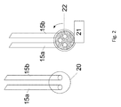
- Fig. 2 shows on the left side a diverter means 13 having a diverter enclosure 20 and at least two fluid connection path 15a, 15b attached to it.
- Fig. 2 further shows on the right side a turning wheel 22 respectively a diverter selection disc that is preferably arranged underneath the diverter enclosure 20.
- the turning wheel 22 comprises multiple holes that can be selectively arranged by turning, in particular by means of a diverter motor respectively diverter actuator element 21, to enable fluid conduction through one or more of the selected fluid paths 15a, 15b, 15a-15b.
- dishwashers 1 have two spray arms 16a, 16b so that all examples are given that way but it is also possible more than two arm assembly.
- the present invention refers to a dishwasher 1.
- the dishwasher according to the present invention comprises at least a receiving space 2 for receiving goods 4 to be cleaned, a first fluid outlet 5 and a second fluid outlet 6 for subjecting a fluid to different sections within the receiving space 2, a pump unit 12 for pumping the fluid from a fluid source 7 to at least one of said outlets 5, 6, a diverter means 13 for setting up multiple fluid connections 15a, 15b between the outlets 5, 6 and the pump unit 13, wherein according to one fluid connection 15a fluid is outputted via the first outlet 5 and wherein according to another fluid connection 15b fluid is outputted via the second outlet 6, and a control unit 10 for selecting a fluid connection 15a, 15b, wherein the control unit 10 operates the diverter means 13 in dependency of an established fluid connection 15a to set up a selected fluid connection 15b.
- the established fluid connection 15a is hereby identified in dependency of an operation parameter of the pump unit 12.
Landscapes
- Engineering & Computer Science (AREA)
- Water Supply & Treatment (AREA)
- Washing And Drying Of Tableware (AREA)
Abstract
The present invention refers to a dishwasher (1). The dishwasher according to the present invention comprises at least a receiving space (2) for receiving goods (4) to be cleaned, a first fluid outlet (5) and a second fluid outlet (6) for subjecting a fluid to different sections within the receiving space (2), a pump unit (12) for pumping the fluid from a fluid source (7) to at least one of said outlets (5, 6), a diverter means (13) for setting up multiple fluid connections (15a, 15b) between the outlets (5, 6) and the pump unit (13), wherein according to one fluid connection (15a) fluid is outputted via the first outlet (5) and wherein according to another fluid connection (15b) fluid is outputted via the second outlet (6), and a control unit (10) for selecting a fluid connection (15a, 15b), wherein the control unit (10) operates the diverter means (13) in dependency of an established fluid connection (15a) to set up a selected fluid connection (15b). The established fluid connection (15a) is hereby identified in dependency of an operation parameter of the pump unit (12).
Description
- The present invention refers to a dishwasher according to
claim 1 and to a method according toclaim 11. - Some of the known dishwashers, especially high-end ones, are capable to use half capacity for small number of dishes to use less water and energy. For this purpose, they only send water to one of the rack (basket) spray arm. The main part used for this purpose is a diverter, which consists of a turning wheel with two holes (or more) and markers on this wheel.
- Current control mechanisms of diverters are complex. First of all, when the system starts the initial position is not known. So, the diverter automatically starts to turn. On the other hand, a switch (or similar) is reading the markings of the wheel, which is different than other and the sizes are defined in datasheet. As a result, MCU need to read markings to get exact diverter position it is also necessary to have such an initial turn to get the position data.
- Document
US20120125382A discloses a dishwasher that comprises a tub defining a wash chamber and having an open face providing access to the wash chamber, a door selectively closing the open face, at least one dish rack located within the wash chamber, at least one sprayer located within the wash chamber, at least one nozzle having at least one aperture located in the wash chamber beneath the at least one dish rack, a liquid supply providing liquid to the at least one sprayer and the at least one nozzle, and a diverter valve selectively fluidly coupling the liquid supply to the at least one sprayer and the at least one nozzle, wherein actuation of the diverter valve controls the supply of liquid from the liquid supply to one of the at least one sprayer and the at least one nozzle. - Document
US20070119488A discloses a dish washer which includes a disc type passage control valve formed to have a simple disc structure, thereby being capable of smoothly supplying wash water to a washing arm. The dish washer includes an upper washing arm, a lower washing arm, a sump for receiving wash water, a washing pump for pumping the wash water, and a passage control valve including a passage opening/closing plate having a plate or disc shape and functioning to open/close a passage guiding the wash water to the upper washing arm or to the lower washing arm. - Document
US20040173245A describes a dishwasher, which comprises a tub having bottom, opposing side, rear and top walls which collectively define a washing chamber adapted to receive and cleanse soiled kitchenware; at least one wash arm for spraying washing fluid onto kitchenware placed into the washing chamber; a pumping unit, including a motor, for directing washing fluid to the at least one wash arm; a filter chamber, adapted to receive a portion of the washing fluid, for entrapping soil from the washing fluid while permitting cleansed washing fluid to be directed back into the washing chamber; a drain exposed to the filter chamber; an overflow tube leading upwardly from the filter chamber such that washing fluid can rise within the overflow tube upon collection of soil in the filter chamber; a sensor for signaling a presence of washing fluid in the overflow tube; and a controller, linked to the sensor, for initiating a drain operation for the dishwasher. - Document
US7350527B2 discloses a filter system for a dishwasher having a floor, a wash pump and a drain pump, the filter system comprising: a sump in the floor having a sidewall and a bottom wall having an inlet leading to the wash pump and an inlet leading to the drain pump; a filter assembly positioned in the sump including: a generally vertical filter retainer and an overlying perforate hood; a multiple porosity filter element carried on the filter retainer; and a back wash sprayer connected to the wash pump and rotatable mounted inside the filter retainer and having at least one nozzle directed toward the filter element; and a dishwasher control, and a pressure sensor positioned on the sidewall of the sump to detect accumulation of soil particles on the filter element and connected to the dishwasher control and arranged to activate the drain pump to remove soil particles from the sump when a predetermined accumulation of soil particles is detected, the sensor being arranged to detect that the back wash sprayer is rotating and the dishwasher control is arranged to provide a check filter signal to the user when the sensor fails to detect back wash sprayer rotation; wherein the inlet leading to the wash pump is positioned inside the filter assembly and the inlet leading to the drain pump is positioned outside the filter assembly. - Document
US2015265128A discloses a method and a device for, detecting clogging of a dishwasher filter. The device is arranged to drain the dishwasher on process water, measure operating current of a motor driving a dishwasher drain pump and determine whether the dishwasher filter is clogged based on the measured drain pump motor operating current. - Document
US20060219262A discloses a control device and method for detecting and controlling a water fill level in a dishwasher or other similar appliance that includes a pump motor. The control monitors the pump motor current over time, determines a current change, and compares the current change to a threshold current change that is indicative of the water level. - Document
US7776159A1 discloses a control system for controlling a fill operation of a dishwasher having a pump and a pump motor driving the pump, and the dishwasher having a valve for controlling the flow of water to the dishwasher includes a monitoring device configured to be coupled to at least one of the pump and the pump motor. The monitoring device generates an output relating to at least one of an operating current and a speed of the pump motor. The control system also includes a controller configured to be operatively coupled to the valve, wherein the controller receives the output and is configured to operate the valve based on the output. The output relates to a fill condition of the dishwasher. - Thus, the prior art dishwashers are not able to control a diverter mechanism without feedback.
- Therefore, it is the object of the present invention to provide an improved dishwasher, in particular a dishwasher that controls a diverter mechanism in a beneficial manner.
- The before mentioned object is solved by a dishwasher according to
claim 1. The dishwasher according to the invention comprises preferably at least a receiving space for receiving goods, in particular dishes, to be cleaned, a first fluid outlet and a second fluid outlet for subjecting a fluid to different sections within the receiving space, a pump unit for pumping the fluid from a fluid source to at least one of said outlets, a diverter means for setting up multiple fluid connections between the outlets and the pump unit, wherein according to one fluid connection fluid is outputted via the first outlet and wherein according to another fluid connection fluid is outputted via the second outlet, and a control unit for selecting a fluid connection, wherein the control unit operates the diverter means in dependency of an established fluid connection to set up the selected fluid connection. The established fluid connection is thereby identified in dependency of an operation parameter of the pump unit. - This solution is beneficial since the diverter means respectively the overall diverter assembly has no feedback output. MCU reads the water pump currents. In initial position MCU starts to pump unit and the pump unit pumps water to diverter.
- According to the present invention the position of the turning wheel is thus preferably estimated by measuring current drawn from water pump, which turns preferably in only one direction.
- Since the required power differs in case a defined amount of fluid, in particular a liquid, in particular at least containing water, is pumped through a short pipe or through a long pipe or if the average diameter of the pipe is small or large, it can be understood that the necessary power for conducting a fluid from a pump unit to different outlets differs at least due to at least one of said pipe settings. Thus, the pump unit requires different degrees of current in such cases. In case a specific current is measured it can thus be derived from that data, which fluid flow passage is set up by the diverter means. Thus, the position or state or setting of the diverter means can be directly derived from the current consumption of the pump unit. Further feedback routines are therefore not necessary.
- Further preferred embodiments are described with respect to the dependent claims and/or in the following parts of the description.
- According to a preferred embodiment of the present invention the operation parameter is the actual current with which the pump unit is operated. Alternatively, or additionally the operation parameter can be the noise of the pump unit and/or vibrations of the pump unit. This embodiment is beneficial since such parameters are depending on the actual state of operation of the pump unit and are therefore giving a representative information about how the fluid is directed inside the dishwasher.
- The diverting means comprises according to a further preferred embodiment of the present invention an actuator means for mechanically opening or closing of fluid connections between the outlets and the pump unit, wherein at least three differently configured fluid connections can be opened or closed by the actuator means, wherein a first fluid connection connects the first outlet and the pump unit, wherein a second fluid connection connects the second outlet and the pump unit and wherein a third fluid connection connects the first outlet and the second outlet with the pump unit. The first outlet is hereby preferably connected to an upper spray means and the second outlet is hereby preferably connected to a lower spray means, wherein the upper spray means is preferably arranged above, in particular in vertical direction, in particular coaxial, above the lower spray means inside the receiving room, wherein the pump unit is caused to be operated with a first current in case the first fluid connection is selected or wherein the pump unit is caused to be operate with a second current in case the second fluid connection is selected or wherein the pump unit is caused to be operated with a third current in case the third fluid connection is selected, wherein the first current and the second current and the third current differ from each other. The third current is hereby preferably smaller than the first current and/or the second current.
- The diverter means comprises according to a further preferred embodiment of the present invention a turning wheel, wherein the turning wheel has multiple openings, in particular holes, for establishing the fluid connections and wherein the turning wheel can be actuated by the actuator means. The turning wheel has at least two openings and preferably three or at least three openings or four or at least four openings. This embodiment is beneficial since such a diverter means causes less complexity compared with an actuated valve device. It is also easy to actuate and easy to control (due to the present invention). The actuator means can be an electric motor.
- A measurement means for measuring the operation parameter, in particular the current consumption, during operation of the pump unit is provided according to a further preferred embodiment of the present invention. The measurement means preferably outputs signals or data representing the operation parameter, in particular the current consumption, of the pump unit.
- The inventive dishwasher comprises according to a further preferred embodiment of the present invention more than two outlets and more than three different fluid connections. The outlets are preferably arranged in such a manner that different areas within the receiving space can be subjected with fluid. It is alternatively possible that the same area within the receiving space can be subjected via the openings in different, in particular opposing, directions. Particular preferably multiple receiving baskets, that can be arranged on different levels within the receiving space, are provided. Preferably each basket can be subjected with fluid via one, in particular dedicated, opening.
- The pump unit preferably comprises a pump element and a pump actuator element, wherein the operation parameter represents an operation parameter of the pump actuator element. The pump actuator element is preferably a motor, in particular an electric, pneumatic or hydraulic motor.
- According to a further preferred embodiment of the present invention a selection means for selecting a specific washing routine out of multiple washing routines by a user is provided. The multiple washing routines are preferably stored in a data memory and executable by the control unit, wherein at least two washing routines differ with respect to the routing of the fluid. The control unit preferably operates the diverter means in dependency of a routine selected by the selection means. This embodiment is beneficial, since different routines can be applied. One routine might be applied in case goods, in particular dishes, to be cleaned are arranged in a specific section or area within the dishwasher. In this case the diverter means can be set to conduct fluid to the respective area, thus energy and water can be saved.
- The before mentioned object is also solved by a method according to claim 11 for operating a dishwasher. The inventive method preferably comprises at least the steps: Measuring of at least one parameter of a pump unit during operation of that pump unit and operating a diverter means for establishing of a predefined fluid connection between the pump unit and at least one of several outlets out of multiple fluid connections in dependency of the measured parameter. This method is beneficial since no feedback loop between the diverter means and the pump unit is required, thus the desired setting can be set up much faster compared to the solutions known from the art.
- According to a further preferred embodiment of the present invention the operation parameter is measured, in particularly constantly or sequentially measured, by a measurement means during operation of the dishwasher. The measurement means preferably outputs signals or data representing the operation parameter, wherein the signals or data are directed to a control unit, wherein the control unit controls the diverter means, in particular at least or timewise or partly, in dependency of the signals or data outputted by the measurement means.
- An actuator element of the diverter means is preferably operated by the control unit in dependency of a selection command, in particular a routine, stored in a memory or a manually inputted command, and in dependency of the measured parameter, wherein the measured parameter is preferably represented by a value, wherein said value differs between a starting value that represents the initially established fluid connection and a target value that represents the selected fluid connection, wherein the actuator element is operated until the target value is measured.
- The control unit preferably determines data about the selected fluid connection in dependency of the measured parameter of the pump unit. Additionally, or as a next step the control unit preferably causes the diverter means to establish different fluid connections in a row, wherein the control unit, in particularly constantly, identifies the presently established fluid connection by an evaluation of the present pump unit parameter.
- Further benefits, goals and features of the present invention will be described by the following specification of the attached figures, in which components of the invention are exemplarily illustrated. Components of the systems and methods according to the inventions, which match at least essentially with respect to their function can be marked with the same reference sign, wherein such components do not have to be marked or described in all figures.
- In the following the invention is just exemplarily described with respect to the attached figures.
-
- Fig. 1
- shows a schematic illustration of a dishwasher according to the present invention and
- Fig. 2
- shows a schematic illustration of a diverter means and a schematic illustration of the turning wheel of the diverter means.
-
Fig. 1 shows adishwasher 1. Theinventive dishwasher 1 comprises at least a control means 10 and a motor driver respectively actuation means 11 for powering a pump element and a diverter means 13. It can be alternatively understood that the pump element and the actuation means 11 are forming thepump unit 12. A measurement means 25 for measuring of at least one operation parameter of thepump unit 12 is preferably arranged between the pump element and the actuation means 11 or at the pump element. The measurement means 25 preferably measures the current consumption of the pump element during operation of the pump element. A signal or data representing the measured current is generated by the measurement means 25. Said signal or data is then preferably transferred alongconnection 19 as feedback to controlunit 10. The pump element feeds fluid, in particular water or a liquid containing water, from asource 7 via a diverter means 13 and viaoutlets 5 and/or 6 to a receivingspace 2.Reference number 14a indicates a fluid connection between thesource 7 and thepipe unit 12 andreference number 14b indicates a fluid connection between thepump unit 12 and the diverter means 13. - Thus, the measurement means 25 outputs data or signals representing the measured parameter, wherein the data or signals are routed to the control means 10. The control means 10 analyzes or evaluates or handles the received data or signals in a predefined manner. The actuation means 11 is actuated or controlled in dependency of the analyzed or evaluated or handled data or signals. The actuation means 11 preferably provides electric energy to actuate an
actuator element 21. The electric energy is preferably transmitted viaconnection 17. - The diverter means 13 is designed to set up multiple different
fluid conducting paths fluid conducting path 15a connects thepump unit 12 with the first respectivelyupper outlet 5 and anotherfluid connection path 15b connects thepump unit 12 with the second respectivelylower outlet 6. One, some or alloutlets goods 4 to be cleaned can be pre-hold in one or multiple, in particular at least or exactly 2, 3, 4, 5 or more,baskets 3. - Preferably at least three differently configured fluid connections can be opened or closed by the actuator means 21. A
first fluid connection 15a hereby connects thefirst outlet 5 and thepump unit 12. A spray arm means 16a can be attached to saidfirst outlet 5. Asecond fluid connection 15b preferably connects thesecond outlet 6 and thepump unit 12. A second spray arm means 16b can be attached to thesecond outlet 6. The spray arm means 16a, 16b are preferably rotatable arranged within the receivingspace 2. Athird fluid connection 15a-15b is preferably set up by a connection between thefirst outlet 5 and thesecond outlet 6 with thepump unit 12. Eachfluid connection - In case a
fluid connection pump unit 12 is operated the operation parameter, in particular current consumption, can be measured by the measurement means 25. Since the operation parameter of thepump unit 12 varies in dependency of the set up fluid connection each fluid connection can be identified be the respective operation parameter of thepump unit 12. Thus, in case thepump unit 12 is activated the position or setting of the diverter means 13 can be derived from the operation parameter of thepump unit 12. Thus, the diverter means 13 can be actuated to form a specific further setting without the need of a calibration step. In case the diverter means 13 is designed as turn wheel, the turn wheel can be turned in particular in one direction until the value of the measured operation parameter fits to the value that represents the desiredfluid conduction path control unit 10 start to read current drawn from the pump. In the shown case different quantized current levels can occur. E.g. in case the fluid connection path comprises bothfluid connection paths pump unit 12 is operated with the lowest current, since the resistance of the fluid connection path is lowest. In case the upperfluid path 15a is closed and thelower fluid path 15b is opened thepump unit 12 is operated with a mid-level current. Further, in case the upperfluid connection path 15a is opened and the lowerfluid connection path 15b is closed thepump unit 12 is operated with the highest current level. With continues reading of currents,MCU 10 will keep exact diverter means 13 position. - If the user wants to change cleaning mode or only one
basket 3 will be used for any reason for dishwashing, the diverter means 13 is energized anddiverter disc 22 changes its position when a new position is set, MCU/Mainboard 10 understands the position by just measuring currents according to the before mentioned limitations. -
Fig. 2 shows on the left side a diverter means 13 having adiverter enclosure 20 and at least twofluid connection path -
Fig. 2 further shows on the right side aturning wheel 22 respectively a diverter selection disc that is preferably arranged underneath thediverter enclosure 20. Theturning wheel 22 comprises multiple holes that can be selectively arranged by turning, in particular by means of a diverter motor respectivelydiverter actuator element 21, to enable fluid conduction through one or more of the selectedfluid paths - Most of
dishwashers 1 have twospray arms - Thus, the present invention refers to a
dishwasher 1. The dishwasher according to the present invention comprises at least a receivingspace 2 for receivinggoods 4 to be cleaned, a firstfluid outlet 5 and a secondfluid outlet 6 for subjecting a fluid to different sections within the receivingspace 2, apump unit 12 for pumping the fluid from afluid source 7 to at least one of saidoutlets multiple fluid connections outlets pump unit 13, wherein according to onefluid connection 15a fluid is outputted via thefirst outlet 5 and wherein according to anotherfluid connection 15b fluid is outputted via thesecond outlet 6, and acontrol unit 10 for selecting afluid connection control unit 10 operates the diverter means 13 in dependency of an establishedfluid connection 15a to set up a selectedfluid connection 15b. The establishedfluid connection 15a is hereby identified in dependency of an operation parameter of thepump unit 12.Reference numbers 1 Dishwasher 16a Upper spray arm (upper basket) 2 Receiving space 16b Lower spray arm (lower basket) 3 Basket 17 Control and energy for diverter actuator element or diverter disc turning motor (21) 4 Goods 5 First fluid outlet 18 Control and energy for pump means 6 second fluid outlet 7 fluid source 19 Current measurement feedback 10 control unit or mainboard or MCU 20 Diverter enclosure 11 actuator element or motor driver 21 Diverter motor or diverter actuator element 12 pump unit 13 Diverter means 22 Diverter selection disc or turning wheel 14a Water in to pump 23 first opening 14b Water in to diverter 24 second opening 15a Water to upper spray arm (upper basket) 25 measurement means 15b Water to lower spray arm (lower basket)
Claims (15)
- Dishwasher (1),
at least comprising
a receiving space (2) for receiving goods (4) to be cleaned,
a first fluid outlet (5) and a second fluid outlet (6) for subjecting a fluid to different sections within the receiving space (2),
a pump unit (12) for pumping the fluid from a fluid source (7) to at least one of said outlets (5, 6),
a diverter means (13) for setting up multiple fluid connections (15a, 15b) between the outlets (5, 6) and the pump unit (13), wherein according to one fluid connection (15a) fluid is outputted via the first outlet (5) and wherein according to another fluid connection (15b) fluid is outputted via the second outlet (6), and
a control unit (10) for selecting a fluid connection (15a, 15b), wherein the control unit (10) operates the diverter means (13) in dependency of an established fluid connection (15a) to set up a selected fluid connection (15b),
characterized in that
the established fluid connection (15a) is identified in dependency of an operation parameter of the pump unit (12). - Dishwasher according to claim 1,
characterized in that
the operation parameter is the actual current with which the pump unit (12) is operated. - Dishwasher according to claim 1 or claim 2,
characterized in that
the diverting means (13) comprises an actuator means (21) for mechanically opening or closing of fluid connections (15a, 15b, 15a-15b) between the outlets (5, 6) and the pump unit (12),
wherein at least three differently configured fluid connections can be opened or closed by the actuator means (21),wherein a first fluid connection (15a) connects the first outlet (5) and the pump unit (12),wherein a second fluid connection (15b) connects the second outlet (6) and the pump unit (12) andwherein a third fluid connection (15a-15b) connects the first outlet (5) and the second outlet (6) with the pump unit (12). - Dishwasher according to claim 3,
characterized in that
the first outlet (5) is connected to an upper spray means (16a) and the second outlet (6) is connected to a lower spray means (16b), wherein the upper spray means (16a) is arranged above the lower spray means (16b) inside the receiving space (2), wherein the pump unit (12) is caused to be operate with a first current in case the first fluid connection (15a) is selected or
wherein the pump unit (12) is caused to be operate with a second current in case the second fluid connection (15b) is selected or
wherein the pump unit (12) is caused to be operate with a third current in case the third fluid connection (15a-15b) is selected,
wherein the first current and the second current and the third current differ from each other. - Dishwasher according to claim 4,
characterized in that
the third current is smaller than the first current and the second current. - Dishwasher according to claims 3 to 5,
characterized in that,
the diverter means (13) comprises a turning wheel (22),
wherein the turning wheel (22) has multiple openings (23, 24, 25) for establishing the fluid connections (15a, 15b, 15a-15b) and
wherein the turning wheel (22) can be actuated by the actuator element. - Dishwasher according to any of the preceding claims,
characterized in that
a current measurement means (25) for measuring the current consumption during operation of the pump unit (12) is provided,
wherein the current measurement means (25) outputs signals or data representing the current consumption of the pump unit (12). - Dishwasher according to any of the preceding claims,
characterized in that
more than two outlets (5, 6) and more than three different fluid connections (15a, 15b, 15a-15b) are provided. - Dishwasher according to any of the preceding claims,
characterized in that
the pump unit (12) comprises a pump element and a pump actuator element, wherein the operation parameter represents an operation parameter of the pump actuator element. - Dishwasher according to any of the preceding claims,
characterized in that
a selection means (26) for selecting a specific washing routine out of multiple washing routines by a user is provided,
wherein the multiple washing routines are stored in a data memory and executable by the control unit (10),
wherein at least two washing routines differ with respect to the routing of the fluid,
wherein the control unit (10) operates the diverter means (13) in dependency of a routine selected by the selection means (26). - Method for operating a dishwasher,
at least comprising the steps:measuring of at least one parameter of a pump unit (12) during operation of that pump unit (12),operating a diverter means (13) for establishing of a predefined fluid connection between the pump unit (13) and at least one of several outlets (5, 6) out of multiple fluid connections (15a, 15b, 15a-15b) in dependency of the measured parameter. - Method according to claim 11,
characterized in that
during operation of the dishwasher (1) the operation parameter is preferably constantly measured by a measurement means (25) and the measurement means (25) outputs signals or data, wherein the signals or data are directed to a control unit (10), wherein the control unit (10) controls the diverter means (13). - Method according to claim 12,
characterized in that,
the control unit (10) determines data about the selected fluid connection in dependency of the measured parameter of the pump unit (12). - Method according to claim 12 or claim 13,
characterized in that,
an actuator means (21) of the diverter means (13) is operated by the control unit in dependency of a selection command, in particular a routine stored in a memory or a manually inputted command, and in dependency of the measured parameter,
wherein the measured parameter is represented by a value,
wherein said value differs between a starting value that represents the initially established fluid connection and a target value that represents the selected fluid connection,
wherein the actuator element (21) is operated until the target value is measured. - Method according to claim 11,
characterized in that
the control unit (10) causes the diverter (13) to establish different fluid connections (15a, 15b, 15a-15b) in a row, wherein the control unit (10), in particularly constantly, identifies the presently established fluid connection (15a, 15b, 15a-15b) by an evaluation of the present pump unit (12) parameter.
Priority Applications (2)
| Application Number | Priority Date | Filing Date | Title |
|---|---|---|---|
| EP16182932.0A EP3278701A1 (en) | 2016-08-05 | 2016-08-05 | Dishwasher with diverter means controllable without feedback and method for operating a dishwasher with a diverter means controlled without feedback |
| TR2017/02395A TR201702395A2 (en) | 2016-08-05 | 2017-02-17 | Dishwasher with diverter means controllable without feedback and method for operating a dishwasher with a diverter means controlled without feedback. |
Applications Claiming Priority (1)
| Application Number | Priority Date | Filing Date | Title |
|---|---|---|---|
| EP16182932.0A EP3278701A1 (en) | 2016-08-05 | 2016-08-05 | Dishwasher with diverter means controllable without feedback and method for operating a dishwasher with a diverter means controlled without feedback |
Publications (1)
| Publication Number | Publication Date |
|---|---|
| EP3278701A1 true EP3278701A1 (en) | 2018-02-07 |
Family
ID=56609729
Family Applications (1)
| Application Number | Title | Priority Date | Filing Date |
|---|---|---|---|
| EP16182932.0A Withdrawn EP3278701A1 (en) | 2016-08-05 | 2016-08-05 | Dishwasher with diverter means controllable without feedback and method for operating a dishwasher with a diverter means controlled without feedback |
Country Status (2)
| Country | Link |
|---|---|
| EP (1) | EP3278701A1 (en) |
| TR (1) | TR201702395A2 (en) |
Cited By (2)
| Publication number | Priority date | Publication date | Assignee | Title |
|---|---|---|---|---|
| CN108937804A (en) * | 2018-05-23 | 2018-12-07 | 佛山市顺德区美的洗涤电器制造有限公司 | Water discharge control method, dish-washing machine and computer readable storage medium |
| WO2026073787A1 (en) * | 2024-10-02 | 2026-04-09 | BSH Hausgeräte GmbH | Circulating pump, in particular heat pump, and water-conducting domestic appliance, in particular domestic dishwasher |
Citations (10)
| Publication number | Priority date | Publication date | Assignee | Title |
|---|---|---|---|---|
| US20040173245A1 (en) | 2002-07-02 | 2004-09-09 | Maytag Corporation | Adaptive drain and purge system for a dishwasher |
| US20060219262A1 (en) | 2005-04-04 | 2006-10-05 | Peterson Gregory A | Water fill level control for dishwasher and associated method |
| US20070119488A1 (en) | 2005-10-13 | 2007-05-31 | Kwon Soon Y | Dish washer with disc type passage control valve |
| US7350527B2 (en) | 2004-07-06 | 2008-04-01 | Whirlpool Corporation | Dishwasher filter system |
| US20080149144A1 (en) * | 2006-12-21 | 2008-06-26 | Diehl Ako Stiftung & Co Kg | Adjustment Apparatus for a Control Element of a Water Deflector, Method for Adjustment, and Synchronous Motor for Adjusting the Control Element |
| US20100121497A1 (en) * | 2007-04-12 | 2010-05-13 | BSH Bosch und Siemens Hausgeräte GmbH | Method for detecting the position of a closure element in a water distribution mechanism |
| US7776159B2 (en) | 2005-12-30 | 2010-08-17 | General Electric Company | Methods and apparatus for controlling a dishwasher |
| US20120125382A1 (en) | 2003-06-17 | 2012-05-24 | Whirlpool Corporation | Dishwasher |
| US20120266919A1 (en) * | 2007-08-31 | 2012-10-25 | Bsh Bosch Und Siemens Hausgerate Gmbh | Dishwasher and method for operating a dishwasher |
| US20150265128A1 (en) | 2012-11-08 | 2015-09-24 | Electrolux Home Products Corporation N.V. | Detecting filter clogging |
-
2016
- 2016-08-05 EP EP16182932.0A patent/EP3278701A1/en not_active Withdrawn
-
2017
- 2017-02-17 TR TR2017/02395A patent/TR201702395A2/en unknown
Patent Citations (10)
| Publication number | Priority date | Publication date | Assignee | Title |
|---|---|---|---|---|
| US20040173245A1 (en) | 2002-07-02 | 2004-09-09 | Maytag Corporation | Adaptive drain and purge system for a dishwasher |
| US20120125382A1 (en) | 2003-06-17 | 2012-05-24 | Whirlpool Corporation | Dishwasher |
| US7350527B2 (en) | 2004-07-06 | 2008-04-01 | Whirlpool Corporation | Dishwasher filter system |
| US20060219262A1 (en) | 2005-04-04 | 2006-10-05 | Peterson Gregory A | Water fill level control for dishwasher and associated method |
| US20070119488A1 (en) | 2005-10-13 | 2007-05-31 | Kwon Soon Y | Dish washer with disc type passage control valve |
| US7776159B2 (en) | 2005-12-30 | 2010-08-17 | General Electric Company | Methods and apparatus for controlling a dishwasher |
| US20080149144A1 (en) * | 2006-12-21 | 2008-06-26 | Diehl Ako Stiftung & Co Kg | Adjustment Apparatus for a Control Element of a Water Deflector, Method for Adjustment, and Synchronous Motor for Adjusting the Control Element |
| US20100121497A1 (en) * | 2007-04-12 | 2010-05-13 | BSH Bosch und Siemens Hausgeräte GmbH | Method for detecting the position of a closure element in a water distribution mechanism |
| US20120266919A1 (en) * | 2007-08-31 | 2012-10-25 | Bsh Bosch Und Siemens Hausgerate Gmbh | Dishwasher and method for operating a dishwasher |
| US20150265128A1 (en) | 2012-11-08 | 2015-09-24 | Electrolux Home Products Corporation N.V. | Detecting filter clogging |
Cited By (3)
| Publication number | Priority date | Publication date | Assignee | Title |
|---|---|---|---|---|
| CN108937804A (en) * | 2018-05-23 | 2018-12-07 | 佛山市顺德区美的洗涤电器制造有限公司 | Water discharge control method, dish-washing machine and computer readable storage medium |
| CN108937804B (en) * | 2018-05-23 | 2022-02-22 | 佛山市顺德区美的洗涤电器制造有限公司 | Drainage control method, dishwasher, and computer-readable storage medium |
| WO2026073787A1 (en) * | 2024-10-02 | 2026-04-09 | BSH Hausgeräte GmbH | Circulating pump, in particular heat pump, and water-conducting domestic appliance, in particular domestic dishwasher |
Also Published As
| Publication number | Publication date |
|---|---|
| TR201702395A2 (en) | 2018-02-21 |
Similar Documents
| Publication | Publication Date | Title |
|---|---|---|
| US10524633B2 (en) | Dishwasher and method of controlling the same | |
| US9936850B2 (en) | Dishwasher with controlled rotation of lower spray arm | |
| EP2156778B1 (en) | Dishwasher and controlling method thereof | |
| KR101672284B1 (en) | Dishwasher and Control Method for the same | |
| US6544344B2 (en) | Dishwasher including a turbidity sensor | |
| US20040079400A1 (en) | Dishwasher having a variable speed circulation pump controlled responsive to sensed turbidity | |
| US8968486B2 (en) | Rinse aid release detection method | |
| US7681582B2 (en) | Multiple spray arm dishwashing apparatus and method for assembling same | |
| US20120048300A1 (en) | Filtering method and related dishwasher | |
| US10022034B2 (en) | Dishwasher appliance and method | |
| CN107920711B (en) | Dishwashing Machine Cleaning Notice and In-Situ Dilution Process | |
| CN107928586A (en) | Water basin dish-washing machine and its automatically cleaning control method | |
| CN108135427A (en) | The method for controlling the circulating pump in the utensil for washing and rinsing article | |
| US11986141B2 (en) | Control method of dishwasher | |
| KR102367883B1 (en) | Dishwasher and Method for controlling it | |
| US10314456B2 (en) | Dishwashing appliance and methods of operation | |
| US11234576B2 (en) | Dishwashing appliances and methods for addressing obstruction therein | |
| TR201702395A2 (en) | Dishwasher with diverter means controllable without feedback and method for operating a dishwasher with a diverter means controlled without feedback. | |
| CN111163672B (en) | Dishwasher and method for operating a dishwasher | |
| KR101882506B1 (en) | Dishwasher system | |
| EP3278700B1 (en) | Dishwasher with water valve having volumetric flow control | |
| US20220104684A1 (en) | Dishwashing appliances and methods for evaluating pressure therein | |
| US20250268449A1 (en) | Dishwasher appliance including alternative input means | |
| US12575708B2 (en) | Dishwasher appliance and method for operating a dishwasher appliance including a clean indicator | |
| KR20110057517A (en) | Dishwasher and its control method |
Legal Events
| Date | Code | Title | Description |
|---|---|---|---|
| PUAI | Public reference made under article 153(3) epc to a published international application that has entered the european phase |
Free format text: ORIGINAL CODE: 0009012 |
|
| AK | Designated contracting states |
Kind code of ref document: A1 Designated state(s): AL AT BE BG CH CY CZ DE DK EE ES FI FR GB GR HR HU IE IS IT LI LT LU LV MC MK MT NL NO PL PT RO RS SE SI SK SM TR |
|
| AX | Request for extension of the european patent |
Extension state: BA ME |
|
| STAA | Information on the status of an ep patent application or granted ep patent |
Free format text: STATUS: THE APPLICATION IS DEEMED TO BE WITHDRAWN |
|
| 18D | Application deemed to be withdrawn |
Effective date: 20180808 |