EP3278575B1 - Hearing apparatus - Google Patents
Hearing apparatus Download PDFInfo
- Publication number
- EP3278575B1 EP3278575B1 EP16716013.4A EP16716013A EP3278575B1 EP 3278575 B1 EP3278575 B1 EP 3278575B1 EP 16716013 A EP16716013 A EP 16716013A EP 3278575 B1 EP3278575 B1 EP 3278575B1
- Authority
- EP
- European Patent Office
- Prior art keywords
- microphone
- signal
- hearing
- microphone signal
- unit
- Prior art date
- Legal status (The legal status is an assumption and is not a legal conclusion. Google has not performed a legal analysis and makes no representation as to the accuracy of the status listed.)
- Revoked
Links
- 238000012545 processing Methods 0.000 claims description 26
- 230000003044 adaptive effect Effects 0.000 claims description 25
- 238000001514 detection method Methods 0.000 claims description 3
- 230000000694 effects Effects 0.000 description 17
- 230000005236 sound signal Effects 0.000 description 12
- 230000008901 benefit Effects 0.000 description 8
- 230000009467 reduction Effects 0.000 description 7
- 239000013598 vector Substances 0.000 description 7
- 238000004891 communication Methods 0.000 description 4
- 230000006872 improvement Effects 0.000 description 4
- 230000002452 interceptive effect Effects 0.000 description 4
- 238000000034 method Methods 0.000 description 4
- 230000002238 attenuated effect Effects 0.000 description 3
- 230000005540 biological transmission Effects 0.000 description 3
- 230000000903 blocking effect Effects 0.000 description 3
- 230000006870 function Effects 0.000 description 3
- 239000011159 matrix material Substances 0.000 description 3
- 238000013459 approach Methods 0.000 description 2
- 230000001364 causal effect Effects 0.000 description 2
- 230000003111 delayed effect Effects 0.000 description 2
- 230000004069 differentiation Effects 0.000 description 2
- 238000012546 transfer Methods 0.000 description 2
- 208000016621 Hearing disease Diseases 0.000 description 1
- 208000032041 Hearing impaired Diseases 0.000 description 1
- 230000002411 adverse Effects 0.000 description 1
- 239000000872 buffer Substances 0.000 description 1
- 238000004364 calculation method Methods 0.000 description 1
- 238000006243 chemical reaction Methods 0.000 description 1
- 238000001914 filtration Methods 0.000 description 1
- 238000013507 mapping Methods 0.000 description 1
- 238000005259 measurement Methods 0.000 description 1
- 238000012544 monitoring process Methods 0.000 description 1
- 230000008569 process Effects 0.000 description 1
- 238000011160 research Methods 0.000 description 1
- 238000005070 sampling Methods 0.000 description 1
- 208000027765 speech disease Diseases 0.000 description 1
- 230000004936 stimulating effect Effects 0.000 description 1
- 230000001360 synchronised effect Effects 0.000 description 1
Images


Classifications
-
- H—ELECTRICITY
- H04—ELECTRIC COMMUNICATION TECHNIQUE
- H04R—LOUDSPEAKERS, MICROPHONES, GRAMOPHONE PICK-UPS OR LIKE ACOUSTIC ELECTROMECHANICAL TRANSDUCERS; DEAF-AID SETS; PUBLIC ADDRESS SYSTEMS
- H04R25/00—Deaf-aid sets, i.e. electro-acoustic or electro-mechanical hearing aids; Electric tinnitus maskers providing an auditory perception
- H04R25/40—Arrangements for obtaining a desired directivity characteristic
- H04R25/407—Circuits for combining signals of a plurality of transducers
-
- H—ELECTRICITY
- H04—ELECTRIC COMMUNICATION TECHNIQUE
- H04R—LOUDSPEAKERS, MICROPHONES, GRAMOPHONE PICK-UPS OR LIKE ACOUSTIC ELECTROMECHANICAL TRANSDUCERS; DEAF-AID SETS; PUBLIC ADDRESS SYSTEMS
- H04R25/00—Deaf-aid sets, i.e. electro-acoustic or electro-mechanical hearing aids; Electric tinnitus maskers providing an auditory perception
- H04R25/55—Deaf-aid sets, i.e. electro-acoustic or electro-mechanical hearing aids; Electric tinnitus maskers providing an auditory perception using an external connection, either wireless or wired
- H04R25/552—Binaural
-
- H—ELECTRICITY
- H04—ELECTRIC COMMUNICATION TECHNIQUE
- H04R—LOUDSPEAKERS, MICROPHONES, GRAMOPHONE PICK-UPS OR LIKE ACOUSTIC ELECTROMECHANICAL TRANSDUCERS; DEAF-AID SETS; PUBLIC ADDRESS SYSTEMS
- H04R25/00—Deaf-aid sets, i.e. electro-acoustic or electro-mechanical hearing aids; Electric tinnitus maskers providing an auditory perception
- H04R25/55—Deaf-aid sets, i.e. electro-acoustic or electro-mechanical hearing aids; Electric tinnitus maskers providing an auditory perception using an external connection, either wireless or wired
- H04R25/554—Deaf-aid sets, i.e. electro-acoustic or electro-mechanical hearing aids; Electric tinnitus maskers providing an auditory perception using an external connection, either wireless or wired using a wireless connection, e.g. between microphone and amplifier or using Tcoils
-
- G—PHYSICS
- G10—MUSICAL INSTRUMENTS; ACOUSTICS
- G10L—SPEECH ANALYSIS TECHNIQUES OR SPEECH SYNTHESIS; SPEECH RECOGNITION; SPEECH OR VOICE PROCESSING TECHNIQUES; SPEECH OR AUDIO CODING OR DECODING
- G10L21/00—Speech or voice signal processing techniques to produce another audible or non-audible signal, e.g. visual or tactile, in order to modify its quality or its intelligibility
- G10L21/02—Speech enhancement, e.g. noise reduction or echo cancellation
- G10L21/0208—Noise filtering
- G10L21/0216—Noise filtering characterised by the method used for estimating noise
- G10L2021/02161—Number of inputs available containing the signal or the noise to be suppressed
- G10L2021/02165—Two microphones, one receiving mainly the noise signal and the other one mainly the speech signal
-
- G—PHYSICS
- G10—MUSICAL INSTRUMENTS; ACOUSTICS
- G10L—SPEECH ANALYSIS TECHNIQUES OR SPEECH SYNTHESIS; SPEECH RECOGNITION; SPEECH OR VOICE PROCESSING TECHNIQUES; SPEECH OR AUDIO CODING OR DECODING
- G10L21/00—Speech or voice signal processing techniques to produce another audible or non-audible signal, e.g. visual or tactile, in order to modify its quality or its intelligibility
- G10L21/02—Speech enhancement, e.g. noise reduction or echo cancellation
-
- H—ELECTRICITY
- H04—ELECTRIC COMMUNICATION TECHNIQUE
- H04R—LOUDSPEAKERS, MICROPHONES, GRAMOPHONE PICK-UPS OR LIKE ACOUSTIC ELECTROMECHANICAL TRANSDUCERS; DEAF-AID SETS; PUBLIC ADDRESS SYSTEMS
- H04R5/00—Stereophonic arrangements
- H04R5/027—Spatial or constructional arrangements of microphones, e.g. in dummy heads
Definitions
- the invention relates to a hearing apparatus and to a method for operating a hearing apparatus.
- the hearing apparatus particularly comprises at least one of a first microphone and a second microphone, the first and the second microphone being arranged in at least one of a first hearing device and a second hearing device.
- the hearing apparatus further comprises a third microphone arranged in an external device, particularly in a cell phone, in a smart phone or in an acoustic sensor network. More specifically, the hearing apparatus comprises a first hearing device and a second hearing device which are interconnected to form a binaural hearing device.
- a hearing apparatus using one or more external microphones to enable a directional effect even when using omnidirectional microphones is disclosed, for example, in EP 2 161 949 A2 .
- US 2012/0020503 A1 discloses a hearing aid system capable of increasing the clearness of sound spoken by a speaker while reproducing the incoming direction of the sound spoken by the speaker without using an inverse mapping rule.
- US 2014/0050326 A1 discloses an apparatus including a microphone array and a removing system.
- the microphone array includes a binaural microphone system having first and second transducers, and a voice microphone system having at least one third transducer.
- WO 2008/098590 A1 discloses a communication system, comprising a transmission unit comprising a microphone arrangement having at least two spaced apart microphones, with a separate audio signal channel being dedicated to each microphone, a first ear unit to be worn at the right side of a user's head, a second ear unit to be worn at the left side of the user's head, each ear unit comprising a receiver unit, said transmission unit comprising means for wirelessly transmitting at least a first channel of the audio signals and a second channel of the audio signals to the first and second ear unit, at least one of the receiver units being capable of receiving the at least first and second audio signal channel, at least one of the ear units comprising audio signal processing means for generating processed audio signals taking into account the audio signals received via the at least first and second audio signal channel, with the first ear unit and the second ear unit comprising means for stimulating the user's hearing at the right ear and the left ear, respectively, according to the processed audio signals.
- JP H01-294989 discloses a noise control head set.
- the noise control head set comprises noise signal adder.
- the hearing apparatus comprises at least one of a first microphone and a second microphone which generate a first microphone signal and a second microphone signal, respectively, the first microphone and the second microphone being arranged in at least one of a first hearing device and a second hearing device, a third microphone which generates a third microphone signal, the third microphone being arranged in an external device (i.e. an external microphone), and a signal processing unit, wherein in the signal processing unit the third microphone signal and at least one of the first microphone signal and the second microphone signal are processed together and/or combined to an output signal with an enhanced signal to noise ratio (SNR) compared to the first microphone signal and/or the second microphone signal.
- SNR signal to noise ratio
- the signal processing unit comprises an adaptive noise canceller unit, which is set up that the third microphone signal and at least one of the first microphone signal and the second microphone signal are fed into and further combined to obtain the output signal.
- the adaptive noise canceller unit further comprises a comparing device which is set up that the first microphone signal and the second microphone signal are compared for target speech detection in it, and the comparing device is set up for generating a control signal for controlling the adaptive noise canceller unit.
- the hearing devices are embodied as hearing aids, and in the following description it is further often referred to hearing aids for simplification.
- External microphones i.e. microphones not arranged in a hearing device
- the signals are not combined with the hearing aid signals for further enhancement.
- Current applications simply stream the external microphone signals to the hearing aids.
- Common applications include classroom settings where the target speaker, such as the teacher, wears a FM microphone and the hearing aid user listens to the streamed FM microphone signal.
- WASN's wireless acoustic sensor networks
- the application of WASN's focuses on the placement of microphones near the targeted speaker or near noise sources to yield estimates of the targeted speaker or noise. See, for example Bertrand, A., Moonen, M. "Robust Distributed Noise Reduction in Hearing Aids with External Acoustic Sensor Nodes", EURASIP, 20(4): 279, 1999 .
- the hearing apparatus comprises a left hearing device and a right hearing device which are interconnected to form a binaural hearing device.
- a binaural communication link between the right and the left hearing device is established to exchange or transmit audio signals between the hearing devices.
- the binaural communication link is a wireless link. More preferably, all microphones used in the hearing apparatus are being connected by a wireless communication link.
- the external device is one of a mobile device (e.g. a portable computer), a smart phone, an acoustic sensor and an acoustic sensor element being part of an acoustic sensor network.
- a mobile phone or a smart phone can be strategically placed in front of the hearing device user to receive direct signals from a front target speaker or is during conversation with a front target speaker already in an excellent position when it is weared in a pocket.
- Wireless acoustic sensor networks are used in many different technical applications including hands free telephony in cars or video conferences, acoustic monitoring and ambient intelligence.
- the output signal is coupled into an output coupler of at least one of the first hearing device and the second hearing device for generating an acoustic output signal.
- the hearing device user receives the enhanced audio signal which is output by the signal processing unit using the external microphone signal via the output coupler or receiver of its hearing device.
- the signal processing unit is not necessarily located within one of the hearing devices.
- the signal processing unit may also be a part of an external device.
- the signal processing is executed within the external device, e.g. a mobile computer or a smart phone, and is part of a particular software application which can be downloaded by the hearing device user.
- the hearing device is, for example, a hearing aid.
- the hearing device is embodied as an in-the-ear (ITE) hearing device, in particular as a completely-in-canal (CIC) hearing device.
- ITE in-the-ear
- CIC completely-in-canal
- each of the used hearing devices comprises one single omnidirectional microphone.
- the first hearing device comprises the first microphone and the second hearing device comprises the second microphone.
- the invention does also cover embodiments where a single hearing device, particularly a single hearing aid, comprises a first and a second microphone.
- the signal processing unit comprises an adaptive noise canceller unit, into which the third microphone signal and at least one of the first microphone signal and the second microphone signal are fed and further combined to obtain an enhanced output signal.
- the third microphone signal is particularly used like a beamformed signal to enhance the signal to noise ratio by spatial filtering. Due to its strategic placement a third microphone signal as such shows a natural directivity.
- the adaptive noise canceller unit at least one of the first microphone signal and the second microphone signal is preprocessed to yield a noise reference signal and the third microphone signal is combined with the noise reference signal to obtain the output signal.
- the first and/or the second microphone signal are specifically used for noise estimation due to the aforementioned body-shielding effect.
- the first microphone signal and the second microphone signal are combined to yield the noise reference signal
- a difference signal of the first microphone signal and the second microphone signal is formed.
- the difference signal can be regarded as an estimation of the noise signal.
- the adaptive noise canceller unit further comprises a target equalization unit, in which the first microphone signal and the second microphone signal are equalized with regard to target location components and wherein the equalized first microphone signal and the equalized second microphone signal are combined to yield the noise reference signal.
- a target equalization unit in which the first microphone signal and the second microphone signal are equalized with regard to target location components and wherein the equalized first microphone signal and the equalized second microphone signal are combined to yield the noise reference signal.
- the adaptive noise canceller unit further comprises a comparing device in which the first microphone signal and the second microphone signal are compared for target speech detection, the comparing device generating a control signal for controlling the adaptive noise canceller unit, in particular such that the adaptive noise canceller unit is adapting only during the absence of target speech activity.
- This embodiment has the particular advantage of preventing target signal cancellation due to target speech leakage.
- the signal processing unit further comprises a calibration unit and/or a equalization unit, wherein the third microphone signal and at least one of the first microphone signal and the second microphone signal are fed into the calibration unit for a group delay compensation and/or into the equalization unit for a level and phase compensation, and wherein the compensated microphone signals are fed into the adaptive noise canceller unit.
- a calibration unit and/or an equalization unit differences between the internal microphone signals and between the internal and external microphone signals in delay time, phase and/or level are compensated.
- the invention exploits the benefits of the body shielding effect in an external microphone for hearing device signal enhancement.
- the external microphone is particularly placed close to the body for attenuating the back directional noise signal.
- the benefit of the body-shielding effect is particularly useful in single microphone hearing aid devices, such as completely-in-canal (CIC) hearing aids, where attenuation of back directional noise at 180° is not feasible.
- CIC completely-in-canal
- the external microphone benefitting from the body-shielding effect with the hearing aids does not suffer from this front back ambiguity as back directional noise is attenuated.
- the signals of the hearing aid microphones can thereby be enhanced to reduce back directional noise by combining the signals of the hearing aids with the external microphone.
- the invention particularly offers additional signal enhancement to the hearing device signals instead of simply streaming the external microphone signal.
- the signal enhancement is provided through combining the signals of the hearing aid with the external microphone.
- the placement of the external microphone exploits the body-shielding effect, where the microphone is near the hearing aid user. Unlike wireless acoustic sensor networks, the placement of the microphone is not placed to be near the targeted speaker or noise sources.
- the invention is defined in claim 1.
- Fig. 1 shows an improved hearing apparatus 1 comprising a first, left hearing device 2 and a second, right hearing device 3.
- the first, left hearing device 2 comprises a first, left microphone 4 and the second, right hearing device 3 comprises a second, right microphone 5.
- the first hearing device 2 and the second hearing device 3 are interconnected and form a binaural hearing device 6 for the hearing device user 7.
- a front target speaker 8 is located.
- an interfering speaker 9 is located.
- a smartphone 10 with a third, external microphone 11 is placed between the hearing device user 7 and the front target speaker 8. Behind the user 7 a zone 12 of back directional attenuation exists due to the body-shielding effect.
- the signals of the hearing device microphones 4, 5 can thereby be enhanced to reduce back directional noise by combining the signals of the hearing device microphones 4, 5 with the signal of the external microphone 11.
- Fig. 2 depicts a scenario that is slightly different to the scenario shown in Fig. 1 .
- An interfering speaker 9 is located at a direction of 135°.
- the third, external microphone 11, in the following referred to also as EMIC, of a smart phone 10 is placed between the hearing device user 7 and a front target speaker 8.
- the hearing devices 2, 3 are, for example, completely-in-canal (CIC) hearing aids (HA) which have one microphone 4, 5 in each device.
- the overall hearing apparatus 1 consists of three microphones 4, 5, 11.
- y L,raw(t) , y R,raw(t) and z raw(t) denote the microphone signals received at the left and right hearing device 2, 3 and at the third external microphone 11 respectively at the discrete time sample t.
- the subband representation of these signals are indexed with k and n where k refers to the k th subband frequency at subband time index n.
- EMIC external microphone 11
- the calibrated EMIC signal is denoted by z calib .
- the calibration is first completed before applying further processing on the EMIC signal.
- the group delay and microphone characteristics inherent to the devices have to be considered.
- the audio delay due to analog to digital conversion and audio buffers is likely to be different between the external device 10 and the hearing devices 2, 3, thus requiring care for compensating for this difference in time delay.
- the group delay of the process between the input signal being received by an internal hearing device microphone 4, 5 and the output signal at a hearing aid receiver (speaker) is orders smaller than in complicated devices like smartphones.
- the group delay of the external device 10 is first measured and then compensated if needed. To measure the group delay of the external device 10, one can simply estimate the group delay of the transfer function which the input microphone signal undergoes as it is transmitted as an output of the system.
- the input signal is the front microphone signal and the output is obtained through the headphone port.
- y L,raw and y R,raw are delayed by the measured group delay of the EMIC device.
- the delayed signals are denoted by y L and y R respectively.
- an equalization filter which compensates for level and phase differences for microphone characteristics.
- the EQ filter is applied to match the EMIC signal to either y L or y R , which serves as a reference denoted as y ref .
- the EQ filter coefficients, h cal are calculated off-line and then applied during online processing. To calculate these weights off-line, recordings of a white noise signal is first made where the ref- er-ence microphone and EMIC are held in roughly the same location in free field.
- EMIC external microphone 11
- Fig. 2 where the external microphone 11 is centered and in front of the body of the hearing device user 7 at a distance of 20 cm which is a typical distance for a smartphone usage.
- the target speaker 7 is located at 0° while the location of the noise interferer 9 is varied along a 1 m radius circle around the hearing device user 7.
- the location of the speech interferer 9 is varied in 45° increments and each location has an unique speech interferer 9 with different sound levels.
- the SNR of the EMIC and the CIC hearing aids 2, 3 are then compared when a single speech interferer 9 is active along with the target speaker 8. As a result, it was shown that the raw EMIC signal has a higher SNR than the raw hearing aid signal when the noise interferer 8 is coming from angles in the range of 135-225°. Additionally, it was shown that the SNR of the EMIC has similar performance of a signal processed using an adaptive first order differential beamformer (FODBF) realized on a two microphone behind-the-ear (BTE) hearing device. It should be noted that the FODBF cannot be realized on single microphone hearing aid devices such as the CICs since the FODBF would require at least two microphones in each device. Therefore, the addition of an external microphone 11 can lead to possibilities in attenuating noise coming from the back direction for single microphone hearing aid devices 2, 3.
- FODBF adaptive first order differential beamformer
- the following exemplary embodiment presents a combination scheme using a Generalized Sidelobe Canceller (GSC) structure for creating an enhanced binaural signal using the three microphones according to a scenario shown in Fig. 1 or Fig. 2 , assuming a binaural link between the two hearing devices 2, 3.
- GSC Generalized Sidelobe Canceller
- a GSC beam-former is composed of a fixed beamformer, a blocking matrix (BM) and an adaptive noise canceller (ANC).
- BM blocking matrix
- ANC adaptive noise canceller
- the overall combination scheme is shown in Fig. 3 where hardware calibration is first performed on the signal of the external microphone, following with a GSC combination scheme for noise reduction, resulting in an enhanced mono signal referred to as z enh .
- the signal processing unit 14 comprises a calibration unit 15 and an equalization unit 16.
- the output signals of the calibration and equalization unit 14, 15 are then fed to a GSC-type processing unit 17, which is further referred to as an adaptive noise canceller unit comprising the ANC.
- the EMIC signal is used in place of the beamformed signal due to its body-shielding benefit.
- the BM combines the signals of the hearing device pair signals to yield a noise reference.
- the ANC is realized using a normalized least mean squares (NLMS) filter.
- NLMS normalized least mean squares
- the GSC structure or the structure of the adaptive noise canceller unit 17, respectively, is shown in Fig. 4 and is implemented in the subband domain.
- the blocking matrix BM is denoted with reference numeral 18.
- the ANC is denoted with reference numeral 19.
- y L,EQ and y R,EQ refer to the left and right hearing device signals after target equalization (in target equalization unit 20) and n BM refers to the noise reference signal.
- the target equalization unit 20 equalizes target speech components in the HA pair.
- y R is a vector of current and past L tarEQ - 1 values of y R and L tarEQ is the length of h tarEQ .
- the ANC is implemented with a subband NLMS algorithm.
- the purpose of the ANC is to estimate and remove the noise in the EMIC signal, z calib .
- the result is an enhanced EMIC signal.
- One of the inputs of the ANC is n BM , a vector of length L ANC containing the current and L ANC - 1 pass values of n BM .
- a causality delay, D is introduced to z calib to ensure a causal system.
- d k n z calib k , n ⁇ D where d ( k, n ) is the primary input to the NLMS.
- the NLMS filter is controlled such that it is adapted only during the absence of target speech activity.
- the target speech activity is determined by comparing in a comparing device 21 (see Fig. 4 ) the following power ratio to a threshold T k .
- the power ratio considers the average power of the difference of the HA signals over average power of the sum.
- the numerator of the ratio in the above formula is less than the denominator. This is due to equalization of the target signal components between the HA pair, thereby subtraction leads to cancellation of the target signal.
- the noise components, generated by interferers as point sources, are uncorrelated and would not cancel. The power of the difference versus the addition of the noise components would be roughly the same.
- T k target activity is present.
- the target speech and noise signals are denoted with the subscripts of s and n respectively to differentiate between target speech and noise.
- the GSC method is tested in various back directional noise scenarios. Using the separately processed signals, z enh,s (k, n) and z enh,n (k, n), the true SNR values of the GSC enhanced signals and raw microphone signals are calculated in decibels and summarized in the following Table 1.
- the segmental SNR is calculated in the time domain using a block size of 30 ms and 50% overlap.
- Table 1 Measures of GSC Performance in dB. Interferer Location SNR of y L SNR of y R SNR of z calib SNR of z enh P s_dist P n_red 135° 7.2 0.9 10.8 15.2 18.2 4.2 180° 5.5 5.0 11.2 11.2 28.5 1.3e-2 225° 5.3 7.9 13.9 16.9 19.0 3.1 135° + 225° 3.1 0.1 9.1 9.9 21.5 0.8
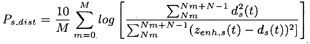
- the speech distortion, P s_dist is estimated by comparing d s , the target speech signal in d prior to GSC processing, and the enhanced signal z enh,s , over M frames of N samples.
- N is chosen to correspond to 30 ms of samples and the frames have an overlap of 50%.
- P n _ red 10 log E d n 2 t E z enh , n 2 t .
- d n refers to the noise signal in d.
- External microphones have been proven to be a useful hearing device accessory when placed in a strategic location where it benefits from a high SNR. Addressing the inability for single microphone binaural hearing devices to attenuate noise from the back direction, the invention leads to attenuation of back interferers due to the body-shielding effect.
- the presented GSC noise reduction scheme provides further enhancement of the EMIC signal for SNR improvement with minimal speech distortion.
Landscapes
- Engineering & Computer Science (AREA)
- Computer Networks & Wireless Communication (AREA)
- Health & Medical Sciences (AREA)
- General Health & Medical Sciences (AREA)
- Neurosurgery (AREA)
- Otolaryngology (AREA)
- Physics & Mathematics (AREA)
- Acoustics & Sound (AREA)
- Signal Processing (AREA)
- Circuit For Audible Band Transducer (AREA)
Description
- The invention relates to a hearing apparatus and to a method for operating a hearing apparatus. The hearing apparatus particularly comprises at least one of a first microphone and a second microphone, the first and the second microphone being arranged in at least one of a first hearing device and a second hearing device. The hearing apparatus further comprises a third microphone arranged in an external device, particularly in a cell phone, in a smart phone or in an acoustic sensor network. More specifically, the hearing apparatus comprises a first hearing device and a second hearing device which are interconnected to form a binaural hearing device.
- A hearing apparatus using one or more external microphones to enable a directional effect even when using omnidirectional microphones is disclosed, for example, in
EP 2 161 949 A2 . -
US 2012/0020503 A1 discloses a hearing aid system capable of increasing the clearness of sound spoken by a speaker while reproducing the incoming direction of the sound spoken by the speaker without using an inverse mapping rule. -
US 2014/0050326 A1 discloses an apparatus including a microphone array and a removing system. The microphone array includes a binaural microphone system having first and second transducers, and a voice microphone system having at least one third transducer. -
WO 2008/098590 A1 discloses a communication system, comprising a transmission unit comprising a microphone arrangement having at least two spaced apart microphones, with a separate audio signal channel being dedicated to each microphone, a first ear unit to be worn at the right side of a user's head, a second ear unit to be worn at the left side of the user's head, each ear unit comprising a receiver unit, said transmission unit comprising means for wirelessly transmitting at least a first channel of the audio signals and a second channel of the audio signals to the first and second ear unit, at least one of the receiver units being capable of receiving the at least first and second audio signal channel, at least one of the ear units comprising audio signal processing means for generating processed audio signals taking into account the audio signals received via the at least first and second audio signal channel, with the first ear unit and the second ear unit comprising means for stimulating the user's hearing at the right ear and the left ear, respectively, according to the processed audio signals. -
JP H01-294989 - It is an object of the invention to specify a hearing apparatus, which enable an improvement of the signal to noise ratio of the audio signal to be output to the user.
- According to the invention, the object is achieved with a hearing apparatus according to claim 1. The hearing apparatus comprises at least one of a first microphone and a second microphone which generate a first microphone signal and a second microphone signal, respectively, the first microphone and the second microphone being arranged in at least one of a first hearing device and a second hearing device, a third microphone which generates a third microphone signal, the third microphone being arranged in an external device (i.e. an external microphone), and a signal processing unit, wherein in the signal processing unit the third microphone signal and at least one of the first microphone signal and the second microphone signal are processed together and/or combined to an output signal with an enhanced signal to noise ratio (SNR) compared to the first microphone signal and/or the second microphone signal. The signal processing unit comprises an adaptive noise canceller unit, which is set up that the third microphone signal and at least one of the first microphone signal and the second microphone signal are fed into and further combined to obtain the output signal. The adaptive noise canceller unit further comprises a comparing device which is set up that the first microphone signal and the second microphone signal are compared for target speech detection in it, and the comparing device is set up for generating a control signal for controlling the adaptive noise canceller unit. Particularly, the hearing devices are embodied as hearing aids, and in the following description it is further often referred to hearing aids for simplification.
- For a given noise scenario, strategic placement of external microphones can offer spatial information and better signal to noise ratio than the hearing aids signals generated by the own internal microphones. Nearby microphones can take advantage of the body of the hearing aid user in attenuating noise signals. For example, when the external microphone is placed in front and close to the body of the hearing aid user, the body shields noise coming from the back direction such that the external microphone picks up a more attenuated noise signal than compared to the hearing aids. This is referred to as the body-shielding effect. The external microphone signals that benefit from the body-shielding effect are then combined with the signals of the hearing aids for hearing aid signal enhancement.
- External microphones, i.e. microphones not arranged in a hearing device, are currently mainly used as hearing aid accessories; however, the signals are not combined with the hearing aid signals for further enhancement. Current applications simply stream the external microphone signals to the hearing aids. Common applications include classroom settings where the target speaker, such as the teacher, wears a FM microphone and the hearing aid user listens to the streamed FM microphone signal. See, for example Boothroyd, A., "Hearing Aid Accessories for Adults: The Remote FM Microphone", Ear and Hearing, 25(1): 22 - 33, 2004; Hawkins, D., "Comparisons of Speech Recognition in Noise by Mildly-to-Moderately Hearing-Impaired Children Using Hearing Aids and FM Systems", Journal of Speech and Hearing Disorders, 49: 409 - 418, 1984; Pittman, A., Lewis, D., Hoover , B., Stelmachowicz P., "Recognition Performance for Four Combinations of FM System and Hearing Aid Microphone Signals in Adverse Listening Conditions", Ear and Hearing, 20(4): 279, 1999.
- There is also a growing research interest in using wireless acoustic sensor networks (WASN's) for signal estimation or parameter estimation in hearing aid algorithms; however, the application of WASN's focuses on the placement of microphones near the targeted speaker or near noise sources to yield estimates of the targeted speaker or noise. See, for example Bertrand, A., Moonen, M. "Robust Distributed Noise Reduction in Hearing Aids with External Acoustic Sensor Nodes", EURASIP, 20(4): 279, 1999.
- According to an exemplary embodiment of the invention the hearing apparatus comprises a left hearing device and a right hearing device which are interconnected to form a binaural hearing device. Particularly, a binaural communication link between the right and the left hearing device is established to exchange or transmit audio signals between the hearing devices. Advantageously, the binaural communication link is a wireless link. More preferably, all microphones used in the hearing apparatus are being connected by a wireless communication link.
- Preferably, the external device is one of a mobile device (e.g. a portable computer), a smart phone, an acoustic sensor and an acoustic sensor element being part of an acoustic sensor network. A mobile phone or a smart phone can be strategically placed in front of the hearing device user to receive direct signals from a front target speaker or is during conversation with a front target speaker already in an excellent position when it is weared in a pocket. Wireless acoustic sensor networks are used in many different technical applications including hands free telephony in cars or video conferences, acoustic monitoring and ambient intelligence.
- According to yet another exemplary embodiment the output signal is coupled into an output coupler of at least one of the first hearing device and the second hearing device for generating an acoustic output signal. According to this embodiment the hearing device user receives the enhanced audio signal which is output by the signal processing unit using the external microphone signal via the output coupler or receiver of its hearing device.
- The signal processing unit is not necessarily located within one of the hearing devices. The signal processing unit may also be a part of an external device. Particularly, the signal processing is executed within the external device, e.g. a mobile computer or a smart phone, and is part of a particular software application which can be downloaded by the hearing device user.
- As already mentioned, the hearing device is, for example, a hearing aid. According to yet another advantageous embodiment the hearing device is embodied as an in-the-ear (ITE) hearing device, in particular as a completely-in-canal (CIC) hearing device. Preferably, each of the used hearing devices comprises one single omnidirectional microphone. Accordingly, the first hearing device comprises the first microphone and the second hearing device comprises the second microphone. However, the invention does also cover embodiments where a single hearing device, particularly a single hearing aid, comprises a first and a second microphone.
- The signal processing unit comprises an adaptive noise canceller unit, into which the third microphone signal and at least one of the first microphone signal and the second microphone signal are fed and further combined to obtain an enhanced output signal. The third microphone signal is particularly used like a beamformed signal to enhance the signal to noise ratio by spatial filtering. Due to its strategic placement a third microphone signal as such shows a natural directivity.
- Advantageously, within the adaptive noise canceller unit at least one of the first microphone signal and the second microphone signal is preprocessed to yield a noise reference signal and the third microphone signal is combined with the noise reference signal to obtain the output signal. The first and/or the second microphone signal are specifically used for noise estimation due to the aforementioned body-shielding effect.
- Preferably, in the adaptive noise canceller unit the first microphone signal and the second microphone signal are combined to yield the noise reference signal Particularly, a difference signal of the first microphone signal and the second microphone signal is formed. In case of a front speaker and a binaural hearing apparatus comprising a left microphone and right microphone, the difference signal can be regarded as an estimation of the noise signal.
- According to yet another preferred embodiment of the invention the adaptive noise canceller unit further comprises a target equalization unit, in which the first microphone signal and the second microphone signal are equalized with regard to target location components and wherein the equalized first microphone signal and the equalized second microphone signal are combined to yield the noise reference signal. Assuming a known target direction, according to a preferred embodiment simply a delay can be added to one of the signals. When a target direction of 0° is assumed (i.e. a front speaker) the left and the right microphone signals of a binaural hearing device are approximately equal due to symmetry.
- The adaptive noise canceller unit further comprises a comparing device in which the first microphone signal and the second microphone signal are compared for target speech detection, the comparing device generating a control signal for controlling the adaptive noise canceller unit, in particular such that the adaptive noise canceller unit is adapting only during the absence of target speech activity. This embodiment has the particular advantage of preventing target signal cancellation due to target speech leakage.
- According to another advantageous embodiment the signal processing unit further comprises a calibration unit and/or a equalization unit, wherein the third microphone signal and at least one of the first microphone signal and the second microphone signal are fed into the calibration unit for a group delay compensation and/or into the equalization unit for a level and phase compensation, and wherein the compensated microphone signals are fed into the adaptive noise canceller unit. With the implementation of a calibration unit and/or an equalization unit differences between the internal microphone signals and between the internal and external microphone signals in delay time, phase and/or level are compensated.
- The invention exploits the benefits of the body shielding effect in an external microphone for hearing device signal enhancement. The external microphone is particularly placed close to the body for attenuating the back directional noise signal. The benefit of the body-shielding effect is particularly useful in single microphone hearing aid devices, such as completely-in-canal (CIC) hearing aids, where attenuation of back directional noise at 180° is not feasible. When using only microphones of the hearing aid system, differentiation between the front (0°) and back (180°) locations is difficult due to the symmetry that exists along the median plane of the body. The external microphone benefitting from the body-shielding effect with the hearing aids does not suffer from this front back ambiguity as back directional noise is attenuated. The signals of the hearing aid microphones can thereby be enhanced to reduce back directional noise by combining the signals of the hearing aids with the external microphone.
- The invention particularly offers additional signal enhancement to the hearing device signals instead of simply streaming the external microphone signal. The signal enhancement is provided through combining the signals of the hearing aid with the external microphone. The placement of the external microphone exploits the body-shielding effect, where the microphone is near the hearing aid user. Unlike wireless acoustic sensor networks, the placement of the microphone is not placed to be near the targeted speaker or noise sources. The invention is defined in claim 1.
- Further details and advantages of the invention become apparent from the subsequent explanation of several exemplary embodiments on the basis of the schematic drawings, not limiting the invention. In the drawings
- Fig. 1
- shows a possible setup of an external microphone benefiting from the body-shielding effect,
- Fig. 2
- shows a setup with hearing aids and a smartphone microphone, target and interfering speakers,
- Fig. 3
- depicts an overview of a signal combination scheme and
- Fig. 4
- shows a more detailed view of an adaptive noise cancellation unit.
-
Fig. 1 shows an improved hearing apparatus 1 comprising a first, left hearing device 2 and a second,right hearing device 3. The first, left hearing device 2 comprises a first,left microphone 4 and the second,right hearing device 3 comprises a second,right microphone 5. The first hearing device 2 and thesecond hearing device 3 are interconnected and form a binaural hearing device 6 for thehearing device user 7. At 0° afront target speaker 8 is located. At 180° an interferingspeaker 9 is located. Asmartphone 10 with a third,external microphone 11 is placed between thehearing device user 7 and thefront target speaker 8. Behind the user 7 azone 12 of back directional attenuation exists due to the body-shielding effect. When using theinternal microphones external microphone 11 benefitting from the body-shielding effect does not suffer from this front-back ambiguity as back directional noise is attenuated. The signals of thehearing device microphones hearing device microphones external microphone 11. -
Fig. 2 depicts a scenario that is slightly different to the scenario shown inFig. 1 . An interferingspeaker 9 is located at a direction of 135°. The third,external microphone 11, in the following referred to also as EMIC, of asmart phone 10 is placed between thehearing device user 7 and afront target speaker 8. Thehearing devices 2, 3 are, for example, completely-in-canal (CIC) hearing aids (HA) which have onemicrophone microphones - Let yL,raw(t), yR,raw(t) and zraw(t) denote the microphone signals received at the left and
right hearing device 2, 3 and at the thirdexternal microphone 11 respectively at the discrete time sample t. The subband representation of these signals are indexed with k and n where k refers to the kth subband frequency at subband time index n. Before combining the microphone signals between the twodevices 2, 3, hardware calibration is needed to match the microphone characteristics of theexternal microphone 11 to themicrophones hearing devices 2, 3. In the examplary approach, the external microphone 11 (EMIC) is calibrated to match one of theinternal microphones - To calibrate for differences in the devices, the group delay and microphone characteristics inherent to the devices have to be considered. The audio delay due to analog to digital conversion and audio buffers is likely to be different between the
external device 10 and thehearing devices 2, 3, thus requiring care for compensating for this difference in time delay. The group delay of the process between the input signal being received by an internalhearing device microphone external device 10 is first measured and then compensated if needed. To measure the group delay of theexternal device 10, one can simply estimate the group delay of the transfer function which the input microphone signal undergoes as it is transmitted as an output of the system. In the case of asmart phone 10, the input signal is the front microphone signal and the output is obtained through the headphone port. To compensate for the group delay, according to a preferred embodiment yL,raw and yR,raw are delayed by the measured group delay of the EMIC device. The delayed signals are denoted by yL and yR respectively. - After compensating for different device latencies, it is recommended to use an equalization filter (EQ) which compensates for level and phase differences for microphone characteristics. The EQ filter is applied to match the EMIC signal to either yL or yR, which serves as a reference denoted as yref. The EQ filter coefficients, h cal, are calculated off-line and then applied during online processing. To calculate these weights off-line, recordings of a white noise signal is first made where the ref- er-ence microphone and EMIC are held in roughly the same location in free field. A least-squares approach is then taken to estimate the relative transfer function for the input zraw to the output yref(k, n) by minimizing the cost function:

- After calibration, in an examplary study a strategic location of the external microphone 11 (EMIC) is considered. For signal enhancement, locations have been explored where the EMIC has a better SNR compared to the signals of the
internal microphones Fig. 2 where theexternal microphone 11 is centered and in front of the body of thehearing device user 7 at a distance of 20 cm which is a typical distance for a smartphone usage. Thetarget speaker 7 is located at 0° while the location of thenoise interferer 9 is varied along a 1 m radius circle around thehearing device user 7. The location of thespeech interferer 9 is varied in 45° increments and each location has anunique speech interferer 9 with different sound levels. The SNR of the EMIC and theCIC hearing aids 2, 3 are then compared when asingle speech interferer 9 is active along with thetarget speaker 8. As a result, it was shown that the raw EMIC signal has a higher SNR than the raw hearing aid signal when thenoise interferer 8 is coming from angles in the range of 135-225°. Additionally, it was shown that the SNR of the EMIC has similar performance of a signal processed using an adaptive first order differential beamformer (FODBF) realized on a two microphone behind-the-ear (BTE) hearing device. It should be noted that the FODBF cannot be realized on single microphone hearing aid devices such as the CICs since the FODBF would require at least two microphones in each device. Therefore, the addition of anexternal microphone 11 can lead to possibilities in attenuating noise coming from the back direction for single microphonehearing aid devices 2, 3. - The following exemplary embodiment presents a combination scheme using a Generalized Sidelobe Canceller (GSC) structure for creating an enhanced binaural signal using the three microphones according to a scenario shown in
Fig. 1 or Fig. 2 , assuming a binaural link between the twohearing devices 2, 3. An ideal data transmission link between the external microphone 11 (EMIC) and thehearing devices 2, 3 with synchronous sampling are also assumed. - For combining the three microphone signals, a variant of a GSC structure is considered. A GSC beam-former is composed of a fixed beamformer, a blocking matrix (BM) and an adaptive noise canceller (ANC). The overall combination scheme is shown in
Fig. 3 where hardware calibration is first performed on the signal of the external microphone, following with a GSC combination scheme for noise reduction, resulting in an enhanced mono signal referred to as zenh. Accordingly, thesignal processing unit 14 comprises a calibration unit 15 and anequalization unit 16. The output signals of the calibration andequalization unit 14, 15 are then fed to a GSC-type processing unit 17, which is further referred to as an adaptive noise canceller unit comprising the ANC. - Analogous to a fixed beamformer of the GSC, the EMIC signal is used in place of the beamformed signal due to its body-shielding benefit. The BM combines the signals of the hearing device pair signals to yield a noise reference. The ANC is realized using a normalized least mean squares (NLMS) filter. The GSC structure or the structure of the adaptive
noise canceller unit 17, respectively, is shown inFig. 4 and is implemented in the subband domain. The blocking matrix BM is denoted withreference numeral 18. The ANC is denoted withreference numeral 19. - The scheme used for the BM becomes apparent in
Figure 4 where yL,EQ and yR,EQ refer to the left and right hearing device signals after target equalization (in target equalization unit 20) and nBM refers to the noise reference signal. Assuming a known target direction, thetarget equalization unit 20 equalizes target speech components in the HA pair. In practice, a causality delay is added to the reference signal to ensure a causal system. For example if yL is chosen as the reference signal for target EQ, then


- In practice, an assumption of a zero degree target location is commonly used in HA applications. This assumes that the hearing device user wants to hear sound that is coming from the centered front which is natural as one tends to face the desired speaker during conversation. When a target direction of 0° is assumed, the left and right hearing device target speaker signals are approximately equal due to symmetry. In this case, target equalization is not crucial and the following assumptions are made

- The ANC is implemented with a subband NLMS algorithm. The purpose of the ANC is to estimate and remove the noise in the EMIC signal, zcalib. The result is an enhanced EMIC signal. One of the inputs of the ANC is n BM, a vector of length LANC containing the current and LANC - 1 pass values of nBM. A causality delay, D, is introduced to zcalib to ensure a causal system.


- To prevent target signal cancellation due to target speech leakage in nBM, the NLMS filter is controlled such that it is adapted only during the absence of target speech activity. The target speech activity is determined by comparing in a comparing device 21 (see
Fig. 4 ) the following power ratio to a threshold Tk. The power ratio considers the average power of the difference of the HA signals over average power of the sum.
- When target speech is active, the numerator of the ratio in the above formula is less than the denominator. This is due to equalization of the target signal components between the HA pair, thereby subtraction leads to cancellation of the target signal. The noise components, generated by interferers as point sources, are uncorrelated and would not cancel. The power of the difference versus the addition of the noise components would be roughly the same. When the ratio in the above equation is less than a predetermined threshold, Tk, target activity is present.
- Using separate speech and noise recordings, the Hagerman method for evaluating noise reduction algorithms is used to evaluate the effect of GSC processing on the speech and noise separately. The target speech and noise signals are denoted with the subscripts of s and n respectively to differentiate between target speech and noise. Let s(k, n) denote the vector of target speech signals and n(k, n) denote the vector of noise signals where s(k, n) = [yL,s (k, n), yR,s (k, n), zs (k, n)] and n(k,n) = [yL,n (k, n), yR,n (k, n), zn (k, n)]. We then define two vectors of input signals of which GSC processing is performed on, a in (k, n) = s(k, n)+ n(k, n) and b in (k, n) = s(k, n) - n(k, n). The resulting processed outputs are denoted by aout (k, n) and bout (k, n) respectively. The output of the GSC processing is the enhanced EMIC signal as shown in
Figure 3 . The processed target speech signal is estimated using zenh,s (k, n) = 0.5(aout (k, n) + bout (k, n)) and the processed noise signals is estimated using zenh,n (k, n) = 0.5(aout(k, n) - bout (k, n)). Following the setup inFigure 2 , the GSC method is tested in various back directional noise scenarios. Using the separately processed signals, zenh,s (k, n) and zenh,n(k, n), the true SNR values of the GSC enhanced signals and raw microphone signals are calculated in decibels and summarized in the following Table 1. The segmental SNR is calculated in the time domain using a block size of 30 ms and 50% overlap.Table 1: Measures of GSC Performance in dB. Interferer Location SNR of yL SNR of yR SNR of zcalib SNR of zenh Ps_dist Pn_red 135° 7.2 0.9 10.8 15.2 18.2 4.2 180° 5.5 5.0 11.2 11.2 28.5 1.3e-2 225° 5.3 7.9 13.9 16.9 19.0 3.1 135° + 225° 3.1 0.1 9.1 9.9 21.5 0.8 - Comparing the SNR of the calibrated external microphone signal to the HA pair, it is clear that the EMIC provides significant SNR improvement. Without GSC processing, strategic placement of the EMIC resulted on average at least 5 dB SNR improvement compared to the raw CIC microphone signal of the better ear. The result of GSC processing leads to further enhancement of at least 2 dB on average when there are noise interferers located at 135° or 225°.
- In addition to SNR, speech distortion and noise reduction is also evaluated in the time domain to quantify the extent of speech deformation and noise reduction resulted from GSC processing. The speech distortion, Ps_dist, is estimated by comparing ds, the target speech signal in d prior to GSC processing, and the enhanced signal zenh,s, over M frames of N samples. N is chosen to correspond to 30 ms of samples and the frames have an overlap of 50%. The equation used is:
- The noise reduction is estimated using:

- External microphones have been proven to be a useful hearing device accessory when placed in a strategic location where it benefits from a high SNR. Addressing the inability for single microphone binaural hearing devices to attenuate noise from the back direction, the invention leads to attenuation of back interferers due to the body-shielding effect. The presented GSC noise reduction scheme provides further enhancement of the EMIC signal for SNR improvement with minimal speech distortion.
-
- 1
- Hearing apparatus
- 2
- First, left hearing device
- 3
- Second, right hearing device
- 4
- First, left microphone
- 5
- Second, right microphone
- 6
- Binaural hearing device
- 7
- Hearing device user
- 8
- Front speaker
- 9
- Interfering speaker
- 10
- external device, e.g. a smartphone
- 11
- Third, external microphone
- 12
- Zone of attenuation
- 14
- Signal processing unit
- 15
- Calibration unit
- 16
- Equalization unit
- 17
- Adaptive noise canceller unit
- 18
- Blocking matrix
- 19
- Adaptive noise canceller
- 20
- Target equalization unit
- 21
- Comparing device
Claims (9)
- Hearing apparatus(1), comprising:at least one of a first microphone (4) and a second microphone (5) which generate a first microphone signal (yL) and a second microphone signal (yR) respectively, the first microphone (4) and the second microphone (5) being arranged in at least one of a first hearing device (2) and a second hearing device (3),a third microphone (11) which generates a third microphone signal (z), the third microphone (11) being arranged in an external device (10), anda signal processing unit (14),wherein the hearing apparatus (1) is setup that in the signal processing unit (14) the third microphone signal (z) and at least one of the first microphone signal (yL) and the second microphone signal (yR) are processed together thereby producing an output signal (zenh) with an enhanced signal to noise ratio compared to the first microphone signal (yR) and/or the second microphone signal (yL),
wherein the signal processing unit (14) comprises an adaptive noise canceller unit (17), which is set up that the third microphone signal (z) and at least one of the first microphone signal (yL) and the second microphone signal (yR) are fed into and further combined to obtain the output signal (zenh), and
wherein the adaptive noise canceller unit (17) further comprises a comparing device (21) which is set up that the first microphone signal (yL) and the second microphone signal (yR) are compared for target speech detection in it, and the comparing device (21) is set up for generating a control signal (spVAD) for controlling the adaptive noise canceller unit (17). - Hearing apparatus (1) as claimed in claim 1,
wherein the external device (10) is one of a mobile device, a smart phone, an acoustic sensor and an acoustic sensor element being part of an acoustic sensor network. - Hearing apparatus (1) as claimed in one of the preceding claims,
wherein the output signal (zenh) is coupled into an output coupler (16) of at least one of the first hearing device (2) and the second hearing device (3) for generating an acoustic output signal. - Hearing apparatus (1) as claimed in one of the preceding claims,
wherein the first hearing device (2) and the second hearing device (3) are each embodied as an in-the-ear hearing device, in particular as a completely-in-canal hearing device. - Hearing apparatus (1) as claimed in one of the preceding claims,
wherein the first hearing device (2) comprises the first microphone (4) and wherein the second hearing device (3) comprises the second microphone (5). - Hearing apparatus (1) as claimed in one of the preceding claims,
wherein the hearing apparatus (1) is setup that in the adaptive noise canceller unit (17) at least one of the first microphone signal (yL) and the second microphone signal (yR) is preprocessed to yield a noise reference signal (nEM) and the third microphone signal (z) is combined with the noise reference signal (nEM) to obtain the output signal (zenh). - Hearing apparatus (1) as claimed in claim 6,
wherein the hearing apparatus (1) is setup that in the adaptive noise canceller unit (17) the first microphone signal (yL) and the second microphone signal (yR) are combined to yield the noise reference signal (nEM). - Hearing apparatus (1) as claimed in 7,
wherein the adaptive noise canceller unit (17) further comprises a target equalization unit (20), which is set up that the first microphone signal (yL) and the second microphone signal (yR) are equalized with regard to target location components in it and wherein the hearing apparatus (1) is setup that the equalized first microphone signal (yL, EQ) and the equalized second microphone signal (yR, EQ) are combined to yield the noise reference signal (nEM). - Hearing apparatus (1) as claimed in one of the claims 1 to 8,
wherein the signal processing unit (14) further comprises a calibration unit (15) and/or a equalization unit (16), wherein the hearing apparatus (1) is setup that the third microphone signal (z) and at least one of the first microphone signal (yL) and the second microphone signal (yR) are fed into the calibration unit (15) for a group delay compensation and/or into the equalization unit (16) for a level and phase compensation, and wherein the hearing apparatus (1) is setup that the compensated microphone signals are fed into the adaptive noise canceller unit (17).
Applications Claiming Priority (2)
| Application Number | Priority Date | Filing Date | Title |
|---|---|---|---|
| EP15162497 | 2015-04-02 | ||
| PCT/EP2016/057271 WO2016156595A1 (en) | 2015-04-02 | 2016-04-01 | Hearing apparatus |
Publications (2)
| Publication Number | Publication Date |
|---|---|
| EP3278575A1 EP3278575A1 (en) | 2018-02-07 |
| EP3278575B1 true EP3278575B1 (en) | 2021-06-02 |
Family
ID=52814861
Family Applications (1)
| Application Number | Title | Priority Date | Filing Date |
|---|---|---|---|
| EP16716013.4A Revoked EP3278575B1 (en) | 2015-04-02 | 2016-04-01 | Hearing apparatus |
Country Status (6)
| Country | Link |
|---|---|
| US (1) | US10798494B2 (en) |
| EP (1) | EP3278575B1 (en) |
| JP (1) | JP6479211B2 (en) |
| CN (1) | CN107431869B (en) |
| DK (1) | DK3278575T3 (en) |
| WO (1) | WO2016156595A1 (en) |
Families Citing this family (5)
| Publication number | Priority date | Publication date | Assignee | Title |
|---|---|---|---|---|
| WO2022054008A1 (en) * | 2020-09-11 | 2022-03-17 | Cochlear Limited | Advanced noise cancellation |
| KR102848942B1 (en) | 2021-02-01 | 2025-08-21 | 삼성전자주식회사 | Method for processing audio data and electronic device supporting the same |
| CN113450819B (en) * | 2021-05-21 | 2024-06-18 | 音科思(深圳)技术有限公司 | Signal processing method and related product |
| CN113689875B (en) * | 2021-08-25 | 2024-02-06 | 湖南芯海聆半导体有限公司 | Digital hearing aid-oriented double-microphone voice enhancement method and device |
| KR102728140B1 (en) * | 2024-01-08 | 2024-11-08 | 주식회사 엠피웨이브 | Bluetooth Earphone Device |
Citations (12)
| Publication number | Priority date | Publication date | Assignee | Title |
|---|---|---|---|---|
| JPH10294989A (en) * | 1997-04-18 | 1998-11-04 | Matsushita Electric Ind Co Ltd | Noise control headset |
| WO2007106399A2 (en) | 2006-03-10 | 2007-09-20 | Mh Acoustics, Llc | Noise-reducing directional microphone array |
| WO2008098590A1 (en) | 2007-02-14 | 2008-08-21 | Phonak Ag | Wireless communication system and method |
| WO2009049645A1 (en) | 2007-10-16 | 2009-04-23 | Phonak Ag | Method and system for wireless hearing assistance |
| US7817808B2 (en) | 2007-07-19 | 2010-10-19 | Alon Konchitsky | Dual adaptive structure for speech enhancement |
| WO2011098142A1 (en) | 2010-02-12 | 2011-08-18 | Phonak Ag | Wireless hearing assistance system and method |
| EP2408222A1 (en) | 2006-12-20 | 2012-01-18 | Phonak AG | Wireless communication system |
| US20120020503A1 (en) | 2009-01-22 | 2012-01-26 | Mitsuru Endo | Hearing aid system |
| US20140050326A1 (en) | 2012-08-20 | 2014-02-20 | Nokia Corporation | Multi-Channel Recording |
| WO2014166525A1 (en) | 2013-04-09 | 2014-10-16 | Phonak Ag | Method and system for providing hearing assistance to a user |
| EP2840807A1 (en) | 2013-08-19 | 2015-02-25 | Oticon A/s | External microphone array and hearing aid using it |
| EP2849462A1 (en) | 2013-09-17 | 2015-03-18 | Oticon A/s | A hearing assistance device comprising an input transducer system |
Family Cites Families (22)
| Publication number | Priority date | Publication date | Assignee | Title |
|---|---|---|---|---|
| DE10045197C1 (en) * | 2000-09-13 | 2002-03-07 | Siemens Audiologische Technik | Operating method for hearing aid device or hearing aid system has signal processor used for reducing effect of wind noise determined by analysis of microphone signals |
| DK1627552T3 (en) | 2003-05-09 | 2008-03-17 | Widex As | Hearing aid system, a hearing aid and a method for processing audio signals |
| ATE420539T1 (en) * | 2003-05-13 | 2009-01-15 | Harman Becker Automotive Sys | METHOD AND SYSTEM FOR ADAPTIVE COMPENSATION OF MICROPHONE INEQUALITIES |
| JP2007531029A (en) | 2004-03-31 | 2007-11-01 | スイスコム モービル アーゲー | Method and system for acoustic communication |
| WO2007028250A2 (en) * | 2005-09-09 | 2007-03-15 | Mcmaster University | Method and device for binaural signal enhancement |
| US8068619B2 (en) * | 2006-05-09 | 2011-11-29 | Fortemedia, Inc. | Method and apparatus for noise suppression in a small array microphone system |
| JP4475468B2 (en) * | 2006-08-07 | 2010-06-09 | リオン株式会社 | Communication listening system |
| KR101449433B1 (en) * | 2007-11-30 | 2014-10-13 | 삼성전자주식회사 | Noise cancelling method and apparatus from the sound signal through the microphone |
| US8223988B2 (en) * | 2008-01-29 | 2012-07-17 | Qualcomm Incorporated | Enhanced blind source separation algorithm for highly correlated mixtures |
| DK2088802T3 (en) | 2008-02-07 | 2013-10-14 | Oticon As | Method for estimating the weighting function of audio signals in a hearing aid |
| DE102008046040B4 (en) | 2008-09-05 | 2012-03-15 | Siemens Medical Instruments Pte. Ltd. | Method for operating a hearing device with directivity and associated hearing device |
| US20110288860A1 (en) | 2010-05-20 | 2011-11-24 | Qualcomm Incorporated | Systems, methods, apparatus, and computer-readable media for processing of speech signals using head-mounted microphone pair |
| US9053697B2 (en) * | 2010-06-01 | 2015-06-09 | Qualcomm Incorporated | Systems, methods, devices, apparatus, and computer program products for audio equalization |
| US8855341B2 (en) | 2010-10-25 | 2014-10-07 | Qualcomm Incorporated | Systems, methods, apparatus, and computer-readable media for head tracking based on recorded sound signals |
| CN102300140B (en) * | 2011-08-10 | 2013-12-18 | 歌尔声学股份有限公司 | Speech enhancing method and device of communication earphone and noise reduction communication earphone |
| KR101236443B1 (en) * | 2012-07-27 | 2013-02-25 | (주)알고코리아 | Wireless in-ear hearing aid system having a remote control function and controlling method therefore |
| US9549253B2 (en) * | 2012-09-26 | 2017-01-17 | Foundation for Research and Technology—Hellas (FORTH) Institute of Computer Science (ICS) | Sound source localization and isolation apparatuses, methods and systems |
| JP6421120B2 (en) | 2012-10-05 | 2018-11-07 | シラス ロジック インターナショナル セミコンダクター リミテッド | Binaural hearing system and method |
| US9148733B2 (en) * | 2012-12-28 | 2015-09-29 | Gn Resound A/S | Hearing aid with improved localization |
| CN103269465B (en) * | 2013-05-22 | 2016-09-07 | 歌尔股份有限公司 | The earphone means of communication under a kind of strong noise environment and a kind of earphone |
| US9036845B2 (en) * | 2013-05-29 | 2015-05-19 | Gn Resound A/S | External input device for a hearing aid |
| CN103686575B (en) * | 2013-11-28 | 2016-08-17 | 清华大学 | Auditory prosthesis |
-
2016
- 2016-04-01 CN CN201680014387.3A patent/CN107431869B/en active Active
- 2016-04-01 EP EP16716013.4A patent/EP3278575B1/en not_active Revoked
- 2016-04-01 JP JP2017551306A patent/JP6479211B2/en active Active
- 2016-04-01 WO PCT/EP2016/057271 patent/WO2016156595A1/en not_active Ceased
- 2016-04-01 DK DK16716013.4T patent/DK3278575T3/en active
-
2017
- 2017-10-02 US US15/722,318 patent/US10798494B2/en active Active
Patent Citations (12)
| Publication number | Priority date | Publication date | Assignee | Title |
|---|---|---|---|---|
| JPH10294989A (en) * | 1997-04-18 | 1998-11-04 | Matsushita Electric Ind Co Ltd | Noise control headset |
| WO2007106399A2 (en) | 2006-03-10 | 2007-09-20 | Mh Acoustics, Llc | Noise-reducing directional microphone array |
| EP2408222A1 (en) | 2006-12-20 | 2012-01-18 | Phonak AG | Wireless communication system |
| WO2008098590A1 (en) | 2007-02-14 | 2008-08-21 | Phonak Ag | Wireless communication system and method |
| US7817808B2 (en) | 2007-07-19 | 2010-10-19 | Alon Konchitsky | Dual adaptive structure for speech enhancement |
| WO2009049645A1 (en) | 2007-10-16 | 2009-04-23 | Phonak Ag | Method and system for wireless hearing assistance |
| US20120020503A1 (en) | 2009-01-22 | 2012-01-26 | Mitsuru Endo | Hearing aid system |
| WO2011098142A1 (en) | 2010-02-12 | 2011-08-18 | Phonak Ag | Wireless hearing assistance system and method |
| US20140050326A1 (en) | 2012-08-20 | 2014-02-20 | Nokia Corporation | Multi-Channel Recording |
| WO2014166525A1 (en) | 2013-04-09 | 2014-10-16 | Phonak Ag | Method and system for providing hearing assistance to a user |
| EP2840807A1 (en) | 2013-08-19 | 2015-02-25 | Oticon A/s | External microphone array and hearing aid using it |
| EP2849462A1 (en) | 2013-09-17 | 2015-03-18 | Oticon A/s | A hearing assistance device comprising an input transducer system |
Non-Patent Citations (2)
| Title |
|---|
| GEUSENS A, ET AL: "Multi-channel noise reduction in hearing aids with wireless access to an external reference signal", MULTI-CHANNEL NOISE REDUCTION IN HEARING AIDS WITH WIRELESS ACCESS TO AN EXTERNAL REFERENCE SIGNAL, 1 January 2012 (2012-01-01), pages 1 - 4, XP055900211, Retrieved from the Internet <URL:https://ieeexplore.ieee.org/stampPDF/getPDF.jsp?tp=&arnumber=6309446&ref=aHR0cHM6Ly9pZWVleHBsb3JlLmllZWUub3JnL2RvY3VtZW50LzYzMDk0NDY=> [retrieved on 20220311] |
| SRIRAM SRINIVASAN: "Using A Remote Wireless Microphone For Speech Enhancement In Non-Stationary Noise", ICASSP, 2011, XP55900212 |
Also Published As
| Publication number | Publication date |
|---|---|
| CN107431869A (en) | 2017-12-01 |
| US10798494B2 (en) | 2020-10-06 |
| WO2016156595A1 (en) | 2016-10-06 |
| DK3278575T3 (en) | 2021-08-16 |
| US20180027340A1 (en) | 2018-01-25 |
| CN107431869B (en) | 2020-01-14 |
| JP6479211B2 (en) | 2019-03-06 |
| EP3278575A1 (en) | 2018-02-07 |
| JP2018521520A (en) | 2018-08-02 |
Similar Documents
| Publication | Publication Date | Title |
|---|---|---|
| US11657793B2 (en) | Voice sensing using multiple microphones | |
| US9723422B2 (en) | Multi-microphone method for estimation of target and noise spectral variances for speech degraded by reverberation and optionally additive noise | |
| CN105898651B (en) | Hearing system comprising separate microphone units for picking up the user's own voice | |
| US10262676B2 (en) | Multi-microphone pop noise control | |
| CN111902866A (en) | Echo control in a binaural adaptive noise cancellation system in a headphone | |
| EP3935631B1 (en) | Voice signal enhancement for head-worn audio devices | |
| CN110100453A (en) | Wind noise is controlled in bilateral microphone array | |
| JP2018137735A (en) | Method and apparatus for streaming communication with a hearing aid device | |
| US10798494B2 (en) | Hearing apparatus | |
| US20230300516A1 (en) | Ear-wearable device with active noise cancellation system that uses internal and external microphones | |
| US12277952B2 (en) | Hearing device comprising a low complexity beamformer | |
| US20120243716A1 (en) | Hearing apparatus with feedback canceler and method for operating the hearing apparatus | |
| US11533555B1 (en) | Wearable audio device with enhanced voice pick-up | |
| US11617037B2 (en) | Hearing device with omnidirectional sensitivity | |
| EP3840402B1 (en) | Wearable electronic device with low frequency noise reduction | |
| US20240276171A1 (en) | Method for processing audio input data and a device thereof | |
| EP3886463B1 (en) | Method at a hearing device |
Legal Events
| Date | Code | Title | Description |
|---|---|---|---|
| STAA | Information on the status of an ep patent application or granted ep patent |
Free format text: STATUS: THE INTERNATIONAL PUBLICATION HAS BEEN MADE |
|
| PUAI | Public reference made under article 153(3) epc to a published international application that has entered the european phase |
Free format text: ORIGINAL CODE: 0009012 |
|
| STAA | Information on the status of an ep patent application or granted ep patent |
Free format text: STATUS: REQUEST FOR EXAMINATION WAS MADE |
|
| 17P | Request for examination filed |
Effective date: 20170822 |
|
| AK | Designated contracting states |
Kind code of ref document: A1 Designated state(s): AL AT BE BG CH CY CZ DE DK EE ES FI FR GB GR HR HU IE IS IT LI LT LU LV MC MK MT NL NO PL PT RO RS SE SI SK SM TR |
|
| AX | Request for extension of the european patent |
Extension state: BA ME |
|
| RAP1 | Party data changed (applicant data changed or rights of an application transferred) |
Owner name: SIVANTOS PTE. LTD. |
|
| RIN1 | Information on inventor provided before grant (corrected) |
Inventor name: KAMKAR-PARSI, HOMAYOUN Inventor name: YEE, DIANNA Inventor name: PUDER, HENNING |
|
| RIN1 | Information on inventor provided before grant (corrected) |
Inventor name: YEE, DIANNA Inventor name: KAMKAR-PARSI, HOMAYOUN Inventor name: PUDER, HENNING |
|
| DAV | Request for validation of the european patent (deleted) | ||
| DAX | Request for extension of the european patent (deleted) | ||
| STAA | Information on the status of an ep patent application or granted ep patent |
Free format text: STATUS: EXAMINATION IS IN PROGRESS |
|
| 17Q | First examination report despatched |
Effective date: 20190215 |
|
| GRAP | Despatch of communication of intention to grant a patent |
Free format text: ORIGINAL CODE: EPIDOSNIGR1 |
|
| STAA | Information on the status of an ep patent application or granted ep patent |
Free format text: STATUS: GRANT OF PATENT IS INTENDED |
|
| INTG | Intention to grant announced |
Effective date: 20200110 |
|
| GRAJ | Information related to disapproval of communication of intention to grant by the applicant or resumption of examination proceedings by the epo deleted |
Free format text: ORIGINAL CODE: EPIDOSDIGR1 |
|
| STAA | Information on the status of an ep patent application or granted ep patent |
Free format text: STATUS: EXAMINATION IS IN PROGRESS |
|
| INTC | Intention to grant announced (deleted) | ||
| GRAP | Despatch of communication of intention to grant a patent |
Free format text: ORIGINAL CODE: EPIDOSNIGR1 |
|
| STAA | Information on the status of an ep patent application or granted ep patent |
Free format text: STATUS: GRANT OF PATENT IS INTENDED |
|
| INTG | Intention to grant announced |
Effective date: 20200626 |
|
| GRAJ | Information related to disapproval of communication of intention to grant by the applicant or resumption of examination proceedings by the epo deleted |
Free format text: ORIGINAL CODE: EPIDOSDIGR1 |
|
| STAA | Information on the status of an ep patent application or granted ep patent |
Free format text: STATUS: EXAMINATION IS IN PROGRESS |
|
| INTC | Intention to grant announced (deleted) | ||
| GRAP | Despatch of communication of intention to grant a patent |
Free format text: ORIGINAL CODE: EPIDOSNIGR1 |
|
| STAA | Information on the status of an ep patent application or granted ep patent |
Free format text: STATUS: GRANT OF PATENT IS INTENDED |
|
| INTG | Intention to grant announced |
Effective date: 20201120 |
|
| RIN1 | Information on inventor provided before grant (corrected) |
Inventor name: YEE, DIANNA Inventor name: PUDER, HENNING Inventor name: KAMKAR-PARSI, HOMAYOUN |
|
| GRAS | Grant fee paid |
Free format text: ORIGINAL CODE: EPIDOSNIGR3 |
|
| GRAA | (expected) grant |
Free format text: ORIGINAL CODE: 0009210 |
|
| STAA | Information on the status of an ep patent application or granted ep patent |
Free format text: STATUS: THE PATENT HAS BEEN GRANTED |
|
| REG | Reference to a national code |
Ref country code: CH Ref legal event code: EP |
|
| AK | Designated contracting states |
Kind code of ref document: B1 Designated state(s): AL AT BE BG CH CY CZ DE DK EE ES FI FR GB GR HR HU IE IS IT LI LT LU LV MC MK MT NL NO PL PT RO RS SE SI SK SM TR |
|
| REG | Reference to a national code |
Ref country code: GB Ref legal event code: FG4D |
|
| REG | Reference to a national code |
Ref country code: AT Ref legal event code: REF Ref document number: 1399573 Country of ref document: AT Kind code of ref document: T Effective date: 20210615 |
|
| REG | Reference to a national code |
Ref country code: IE Ref legal event code: FG4D |
|
| REG | Reference to a national code |
Ref country code: DE Ref legal event code: R096 Ref document number: 602016058780 Country of ref document: DE |
|
| REG | Reference to a national code |
Ref country code: DK Ref legal event code: T3 Effective date: 20210811 |
|
| REG | Reference to a national code |
Ref country code: LT Ref legal event code: MG9D |
|
| PG25 | Lapsed in a contracting state [announced via postgrant information from national office to epo] |
Ref country code: BG Free format text: LAPSE BECAUSE OF FAILURE TO SUBMIT A TRANSLATION OF THE DESCRIPTION OR TO PAY THE FEE WITHIN THE PRESCRIBED TIME-LIMIT Effective date: 20210902 Ref country code: HR Free format text: LAPSE BECAUSE OF FAILURE TO SUBMIT A TRANSLATION OF THE DESCRIPTION OR TO PAY THE FEE WITHIN THE PRESCRIBED TIME-LIMIT Effective date: 20210602 Ref country code: FI Free format text: LAPSE BECAUSE OF FAILURE TO SUBMIT A TRANSLATION OF THE DESCRIPTION OR TO PAY THE FEE WITHIN THE PRESCRIBED TIME-LIMIT Effective date: 20210602 Ref country code: LT Free format text: LAPSE BECAUSE OF FAILURE TO SUBMIT A TRANSLATION OF THE DESCRIPTION OR TO PAY THE FEE WITHIN THE PRESCRIBED TIME-LIMIT Effective date: 20210602 |
|
| REG | Reference to a national code |
Ref country code: NL Ref legal event code: MP Effective date: 20210602 |
|
| REG | Reference to a national code |
Ref country code: AT Ref legal event code: MK05 Ref document number: 1399573 Country of ref document: AT Kind code of ref document: T Effective date: 20210602 |
|
| PG25 | Lapsed in a contracting state [announced via postgrant information from national office to epo] |
Ref country code: GR Free format text: LAPSE BECAUSE OF FAILURE TO SUBMIT A TRANSLATION OF THE DESCRIPTION OR TO PAY THE FEE WITHIN THE PRESCRIBED TIME-LIMIT Effective date: 20210903 Ref country code: LV Free format text: LAPSE BECAUSE OF FAILURE TO SUBMIT A TRANSLATION OF THE DESCRIPTION OR TO PAY THE FEE WITHIN THE PRESCRIBED TIME-LIMIT Effective date: 20210602 Ref country code: RS Free format text: LAPSE BECAUSE OF FAILURE TO SUBMIT A TRANSLATION OF THE DESCRIPTION OR TO PAY THE FEE WITHIN THE PRESCRIBED TIME-LIMIT Effective date: 20210602 Ref country code: SE Free format text: LAPSE BECAUSE OF FAILURE TO SUBMIT A TRANSLATION OF THE DESCRIPTION OR TO PAY THE FEE WITHIN THE PRESCRIBED TIME-LIMIT Effective date: 20210602 Ref country code: PL Free format text: LAPSE BECAUSE OF FAILURE TO SUBMIT A TRANSLATION OF THE DESCRIPTION OR TO PAY THE FEE WITHIN THE PRESCRIBED TIME-LIMIT Effective date: 20210602 Ref country code: NO Free format text: LAPSE BECAUSE OF FAILURE TO SUBMIT A TRANSLATION OF THE DESCRIPTION OR TO PAY THE FEE WITHIN THE PRESCRIBED TIME-LIMIT Effective date: 20210902 |
|
| PG25 | Lapsed in a contracting state [announced via postgrant information from national office to epo] |
Ref country code: AT Free format text: LAPSE BECAUSE OF FAILURE TO SUBMIT A TRANSLATION OF THE DESCRIPTION OR TO PAY THE FEE WITHIN THE PRESCRIBED TIME-LIMIT Effective date: 20210602 Ref country code: ES Free format text: LAPSE BECAUSE OF FAILURE TO SUBMIT A TRANSLATION OF THE DESCRIPTION OR TO PAY THE FEE WITHIN THE PRESCRIBED TIME-LIMIT Effective date: 20210602 Ref country code: RO Free format text: LAPSE BECAUSE OF FAILURE TO SUBMIT A TRANSLATION OF THE DESCRIPTION OR TO PAY THE FEE WITHIN THE PRESCRIBED TIME-LIMIT Effective date: 20210602 Ref country code: PT Free format text: LAPSE BECAUSE OF FAILURE TO SUBMIT A TRANSLATION OF THE DESCRIPTION OR TO PAY THE FEE WITHIN THE PRESCRIBED TIME-LIMIT Effective date: 20211004 Ref country code: NL Free format text: LAPSE BECAUSE OF FAILURE TO SUBMIT A TRANSLATION OF THE DESCRIPTION OR TO PAY THE FEE WITHIN THE PRESCRIBED TIME-LIMIT Effective date: 20210602 Ref country code: CZ Free format text: LAPSE BECAUSE OF FAILURE TO SUBMIT A TRANSLATION OF THE DESCRIPTION OR TO PAY THE FEE WITHIN THE PRESCRIBED TIME-LIMIT Effective date: 20210602 Ref country code: EE Free format text: LAPSE BECAUSE OF FAILURE TO SUBMIT A TRANSLATION OF THE DESCRIPTION OR TO PAY THE FEE WITHIN THE PRESCRIBED TIME-LIMIT Effective date: 20210602 Ref country code: SK Free format text: LAPSE BECAUSE OF FAILURE TO SUBMIT A TRANSLATION OF THE DESCRIPTION OR TO PAY THE FEE WITHIN THE PRESCRIBED TIME-LIMIT Effective date: 20210602 Ref country code: SM Free format text: LAPSE BECAUSE OF FAILURE TO SUBMIT A TRANSLATION OF THE DESCRIPTION OR TO PAY THE FEE WITHIN THE PRESCRIBED TIME-LIMIT Effective date: 20210602 |
|
| REG | Reference to a national code |
Ref country code: DE Ref legal event code: R026 Ref document number: 602016058780 Country of ref document: DE |
|
| PLBI | Opposition filed |
Free format text: ORIGINAL CODE: 0009260 |
|
| PLAX | Notice of opposition and request to file observation + time limit sent |
Free format text: ORIGINAL CODE: EPIDOSNOBS2 |
|
| 26 | Opposition filed |
Opponent name: OTICON A/S Effective date: 20220302 |
|
| PG25 | Lapsed in a contracting state [announced via postgrant information from national office to epo] |
Ref country code: AL Free format text: LAPSE BECAUSE OF FAILURE TO SUBMIT A TRANSLATION OF THE DESCRIPTION OR TO PAY THE FEE WITHIN THE PRESCRIBED TIME-LIMIT Effective date: 20210602 |
|
| PLBB | Reply of patent proprietor to notice(s) of opposition received |
Free format text: ORIGINAL CODE: EPIDOSNOBS3 |
|
| PG25 | Lapsed in a contracting state [announced via postgrant information from national office to epo] |
Ref country code: IT Free format text: LAPSE BECAUSE OF FAILURE TO SUBMIT A TRANSLATION OF THE DESCRIPTION OR TO PAY THE FEE WITHIN THE PRESCRIBED TIME-LIMIT Effective date: 20210602 |
|
| PGFP | Annual fee paid to national office [announced via postgrant information from national office to epo] |
Ref country code: GB Payment date: 20220425 Year of fee payment: 7 Ref country code: FR Payment date: 20220420 Year of fee payment: 7 Ref country code: DK Payment date: 20220421 Year of fee payment: 7 Ref country code: DE Payment date: 20220419 Year of fee payment: 7 |
|
| PGFP | Annual fee paid to national office [announced via postgrant information from national office to epo] |
Ref country code: CH Payment date: 20220421 Year of fee payment: 7 |
|
| RDAF | Communication despatched that patent is revoked |
Free format text: ORIGINAL CODE: EPIDOSNREV1 |
|
| REG | Reference to a national code |
Ref country code: DE Ref legal event code: R103 Ref document number: 602016058780 Country of ref document: DE Ref country code: DE Ref legal event code: R064 Ref document number: 602016058780 Country of ref document: DE |
|
| REG | Reference to a national code |
Ref country code: BE Ref legal event code: MM Effective date: 20220430 |
|
| RDAG | Patent revoked |
Free format text: ORIGINAL CODE: 0009271 |
|
| STAA | Information on the status of an ep patent application or granted ep patent |
Free format text: STATUS: PATENT REVOKED |
|
| PG25 | Lapsed in a contracting state [announced via postgrant information from national office to epo] |
Ref country code: MC Free format text: LAPSE BECAUSE OF FAILURE TO SUBMIT A TRANSLATION OF THE DESCRIPTION OR TO PAY THE FEE WITHIN THE PRESCRIBED TIME-LIMIT Effective date: 20210602 Ref country code: LU Free format text: LAPSE BECAUSE OF NON-PAYMENT OF DUE FEES Effective date: 20220401 |
|
| REG | Reference to a national code |
Ref country code: CH Ref legal event code: PL |
|
| PG25 | Lapsed in a contracting state [announced via postgrant information from national office to epo] |
Ref country code: BE Free format text: LAPSE BECAUSE OF NON-PAYMENT OF DUE FEES Effective date: 20220430 |
|
| 27W | Patent revoked |
Effective date: 20221022 |
|
| GBPR | Gb: patent revoked under art. 102 of the ep convention designating the uk as contracting state |
Effective date: 20221022 |
|
| PG25 | Lapsed in a contracting state [announced via postgrant information from national office to epo] |
Ref country code: MK Free format text: LAPSE BECAUSE OF FAILURE TO SUBMIT A TRANSLATION OF THE DESCRIPTION OR TO PAY THE FEE WITHIN THE PRESCRIBED TIME-LIMIT Effective date: 20210602 Ref country code: CY Free format text: LAPSE BECAUSE OF FAILURE TO SUBMIT A TRANSLATION OF THE DESCRIPTION OR TO PAY THE FEE WITHIN THE PRESCRIBED TIME-LIMIT Effective date: 20210602 |
|
| PG25 | Lapsed in a contracting state [announced via postgrant information from national office to epo] |
Ref country code: IE Free format text: LAPSE BECAUSE OF NON-PAYMENT OF DUE FEES Effective date: 20220401 |
|
| PG25 | Lapsed in a contracting state [announced via postgrant information from national office to epo] |
Ref country code: TR Free format text: LAPSE BECAUSE OF FAILURE TO SUBMIT A TRANSLATION OF THE DESCRIPTION OR TO PAY THE FEE WITHIN THE PRESCRIBED TIME-LIMIT Effective date: 20210602 Ref country code: IE Free format text: LAPSE BECAUSE OF NON-PAYMENT OF DUE FEES Effective date: 20220401 |
|
| PG25 | Lapsed in a contracting state [announced via postgrant information from national office to epo] |
Ref country code: HU Free format text: LAPSE BECAUSE OF FAILURE TO SUBMIT A TRANSLATION OF THE DESCRIPTION OR TO PAY THE FEE WITHIN THE PRESCRIBED TIME-LIMIT; INVALID AB INITIO Effective date: 20160401 |
|
| PG25 | Lapsed in a contracting state [announced via postgrant information from national office to epo] |
Ref country code: MT Free format text: LAPSE BECAUSE OF FAILURE TO SUBMIT A TRANSLATION OF THE DESCRIPTION OR TO PAY THE FEE WITHIN THE PRESCRIBED TIME-LIMIT Effective date: 20210602 |