EP3277335B1 - Systems and methods for leukoreducing a red blood cell-containing fluid and concentrated red blood cells - Google Patents
Systems and methods for leukoreducing a red blood cell-containing fluid and concentrated red blood cells Download PDFInfo
- Publication number
- EP3277335B1 EP3277335B1 EP16715925.0A EP16715925A EP3277335B1 EP 3277335 B1 EP3277335 B1 EP 3277335B1 EP 16715925 A EP16715925 A EP 16715925A EP 3277335 B1 EP3277335 B1 EP 3277335B1
- Authority
- EP
- European Patent Office
- Prior art keywords
- red blood
- fluid
- blood cell
- flow path
- filter
- Prior art date
- Legal status (The legal status is an assumption and is not a legal conclusion. Google has not performed a legal analysis and makes no representation as to the accuracy of the status listed.)
- Active
Links
Images


Classifications
-
- A—HUMAN NECESSITIES
- A61—MEDICAL OR VETERINARY SCIENCE; HYGIENE
- A61M—DEVICES FOR INTRODUCING MEDIA INTO, OR ONTO, THE BODY; DEVICES FOR TRANSDUCING BODY MEDIA OR FOR TAKING MEDIA FROM THE BODY; DEVICES FOR PRODUCING OR ENDING SLEEP OR STUPOR
- A61M1/00—Suction or pumping devices for medical purposes; Devices for carrying-off, for treatment of, or for carrying-over, body-liquids; Drainage systems
- A61M1/02—Blood transfusion apparatus
- A61M1/0209—Multiple bag systems for separating or storing blood components
- A61M1/0218—Multiple bag systems for separating or storing blood components with filters
-
- A—HUMAN NECESSITIES
- A61—MEDICAL OR VETERINARY SCIENCE; HYGIENE
- A61M—DEVICES FOR INTRODUCING MEDIA INTO, OR ONTO, THE BODY; DEVICES FOR TRANSDUCING BODY MEDIA OR FOR TAKING MEDIA FROM THE BODY; DEVICES FOR PRODUCING OR ENDING SLEEP OR STUPOR
- A61M1/00—Suction or pumping devices for medical purposes; Devices for carrying-off, for treatment of, or for carrying-over, body-liquids; Drainage systems
- A61M1/02—Blood transfusion apparatus
- A61M1/0272—Apparatus for treatment of blood or blood constituents prior to or for conservation, e.g. freezing, drying or centrifuging
-
- A—HUMAN NECESSITIES
- A61—MEDICAL OR VETERINARY SCIENCE; HYGIENE
- A61M—DEVICES FOR INTRODUCING MEDIA INTO, OR ONTO, THE BODY; DEVICES FOR TRANSDUCING BODY MEDIA OR FOR TAKING MEDIA FROM THE BODY; DEVICES FOR PRODUCING OR ENDING SLEEP OR STUPOR
- A61M1/00—Suction or pumping devices for medical purposes; Devices for carrying-off, for treatment of, or for carrying-over, body-liquids; Drainage systems
- A61M1/14—Dialysis systems; Artificial kidneys; Blood oxygenators ; Reciprocating systems for treatment of body fluids, e.g. single needle systems for hemofiltration or pheresis
- A61M1/16—Dialysis systems; Artificial kidneys; Blood oxygenators ; Reciprocating systems for treatment of body fluids, e.g. single needle systems for hemofiltration or pheresis with membranes
- A61M1/26—Dialysis systems; Artificial kidneys; Blood oxygenators ; Reciprocating systems for treatment of body fluids, e.g. single needle systems for hemofiltration or pheresis with membranes and internal elements which are moving
- A61M1/262—Dialysis systems; Artificial kidneys; Blood oxygenators ; Reciprocating systems for treatment of body fluids, e.g. single needle systems for hemofiltration or pheresis with membranes and internal elements which are moving rotating
- A61M1/265—Dialysis systems; Artificial kidneys; Blood oxygenators ; Reciprocating systems for treatment of body fluids, e.g. single needle systems for hemofiltration or pheresis with membranes and internal elements which are moving rotating inducing Taylor vortices
-
- A—HUMAN NECESSITIES
- A61—MEDICAL OR VETERINARY SCIENCE; HYGIENE
- A61M—DEVICES FOR INTRODUCING MEDIA INTO, OR ONTO, THE BODY; DEVICES FOR TRANSDUCING BODY MEDIA OR FOR TAKING MEDIA FROM THE BODY; DEVICES FOR PRODUCING OR ENDING SLEEP OR STUPOR
- A61M1/00—Suction or pumping devices for medical purposes; Devices for carrying-off, for treatment of, or for carrying-over, body-liquids; Drainage systems
- A61M1/34—Filtering material out of the blood by passing it through a membrane, i.e. hemofiltration or diafiltration
-
- A—HUMAN NECESSITIES
- A61—MEDICAL OR VETERINARY SCIENCE; HYGIENE
- A61M—DEVICES FOR INTRODUCING MEDIA INTO, OR ONTO, THE BODY; DEVICES FOR TRANSDUCING BODY MEDIA OR FOR TAKING MEDIA FROM THE BODY; DEVICES FOR PRODUCING OR ENDING SLEEP OR STUPOR
- A61M1/00—Suction or pumping devices for medical purposes; Devices for carrying-off, for treatment of, or for carrying-over, body-liquids; Drainage systems
- A61M1/36—Other treatment of blood in a by-pass of the natural circulatory system, e.g. temperature adaptation, irradiation ; Extra-corporeal blood circuits
- A61M1/3621—Extra-corporeal blood circuits
- A61M1/3627—Degassing devices; Buffer reservoirs; Drip chambers; Blood filters
- A61M1/3633—Blood component filters, e.g. leukocyte filters
-
- C—CHEMISTRY; METALLURGY
- C12—BIOCHEMISTRY; BEER; SPIRITS; WINE; VINEGAR; MICROBIOLOGY; ENZYMOLOGY; MUTATION OR GENETIC ENGINEERING
- C12N—MICROORGANISMS OR ENZYMES; COMPOSITIONS THEREOF; PROPAGATING, PRESERVING, OR MAINTAINING MICROORGANISMS; MUTATION OR GENETIC ENGINEERING; CULTURE MEDIA
- C12N5/00—Undifferentiated human, animal or plant cells, e.g. cell lines; Tissues; Cultivation or maintenance thereof; Culture media therefor
- C12N5/06—Animal cells or tissues; Human cells or tissues
- C12N5/0602—Vertebrate cells
- C12N5/0634—Cells from the blood or the immune system
- C12N5/0641—Erythrocytes
-
- A—HUMAN NECESSITIES
- A61—MEDICAL OR VETERINARY SCIENCE; HYGIENE
- A61M—DEVICES FOR INTRODUCING MEDIA INTO, OR ONTO, THE BODY; DEVICES FOR TRANSDUCING BODY MEDIA OR FOR TAKING MEDIA FROM THE BODY; DEVICES FOR PRODUCING OR ENDING SLEEP OR STUPOR
- A61M2202/00—Special media to be introduced, removed or treated
- A61M2202/04—Liquids
- A61M2202/0413—Blood
- A61M2202/0429—Red blood cells; Erythrocytes
Definitions
- the invention relates to blood separation systems and methods. More particularly, the invention relates to blood separation systems and methods also involving leukoreduction of the blood or of a separated cellular blood component.
- such a collection typically employs a pre-assembled arrangement of tubing and containers or bags, including a flexible plastic primary container or bag for receiving a unit of whole blood from a donor and one or more "satellite" containers or bags.
- the blood is first collected in the primary container, which also contains an anticoagulant (typically, but not exclusively, containing sodium citrate, phosphate, and dextrose - often referred to as CPD).
- an anticoagulant typically, but not exclusively, containing sodium citrate, phosphate, and dextrose - often referred to as CPD).
- a preservative (often called an "additive solution" or AS, and commonly containing a saline, adenine, and glucose medium - which is referred to as SAG) may be included as part of a larger assembly of bags and tubes that are used in processing after the blood is collected.
- a blood component processing laboratory commonly referred to as a "back lab,” for further processing.
- Further processing usually entails manually loading the primary container and associated tubing and satellite containers into a centrifuge to separate the whole blood into components such as concentrated red cells and platelet-rich or platelet-poor plasma. These components are then manually expressed from the primary container into other pre-connected satellite containers, and may be again centrifuged to separate the platelets from plasma. Subsequently, the blood components may be leukoreduced (i.e., have the white blood cells or leukocytes contained therein removed) by filtration for further processing or storage. In short, this process is time consuming, labor intensive, and subject to possible human error.
- Such systems may include a membrane-covered spinner having an interior collection system disposed within a stationary shell or housing.
- an inner surface of the stationary housing may be covered by a membrane, or both the spinner and the housing may include associated membranes.
- membrane separators blood is fed into an annular space or gap between the spinner and the shell and moves along the longitudinal axis of the shell toward an exit region. Plasma passes through the membrane and exits through an outlet port, while the remaining cellular blood components (red blood cells, platelets, and white cells) remain in the gap and move to the exit region between the spinner and the shell.
- Membrane separators have been found to provide excellent plasma filtration rates, due primarily to the unique flow patterns ("Taylor vortices”) induced in the gap between the spinning membrane and the shell.
- the Taylor vortices help to keep the blood cells from depositing on and fouling or clogging the membrane.
- membrane separators have been widely used for the collection of plasma, they have not typically been used for the collection of other blood components, specifically red blood cells.
- One example of a membrane separator used in the collection of separated red blood cells is described in PCT Patent Application Publication No. WO 2014/039086 A1 .
- Further prior art includes WO2012/125457 A1 and WO2014/016198 A1 .
- the subject matter disclosed herein provides further advances in membrane separators, particularly in terms of the reduction of leukocytes in a final collected cellular blood component.
- a fluid flow circuit for separating an anticoagulated red blood cell-containing fluid into separated red blood cells and another fluid constituent.
- the fluid flow circuit includes a spinning membrane separator including an inlet port and a red blood cell outlet port and configured to separate an anticoagulated red blood cell-containing fluid into separated red blood cells and another fluid constituent.
- An inlet flow path is in fluid communication with the inlet port and a fluid source container for flowing anticoagulated red blood cell-containing fluid from the fluid source container to the inlet port, with a leukoreduction filter being associated with the inlet flow path and positioned stream of the spinning membrane separator.
- a method for separating an anticoagulated red blood cell-containing fluid into separated red blood cells and another fluid constituent.
- the method involves providing an anticoagulated red blood cell-containing fluid and flowing it through an inlet flow path, into a spinning membrane separator.
- the anticoagulated red blood cell-containing fluid is separated into separated red blood cells and another fluid constituent, and the separated red blood cells are flowed out of the membrane separator via an outlet flow path.
- Prior to the anticoagulated red blood cell-containing fluid entering the membrane separator it is leukoreduced by passing it through a leukocyte reduction filter associated with the inlet flow path.
- a fluid flow circuit for separating a red blood cell-containing fluid into separated red blood cells and another fluid constituent.
- the fluid flow circuit includes a membrane separator having an inlet port and a red blood cell outlet port.
- An inlet flow path is in fluid communication with the inlet port and an outlet flow path is associated with the red blood cell outlet port, with a leukoreduction filter being associated with the outlet flow path.
- a microaggregate filter is positioned between the red blood cell outlet port and the leukoreduction filter.
- a method for separating a red blood cell-containing fluid into separated red blood cells and another fluid constituent.
- the method involves providing a red blood cell-containing fluid and flowing it through an inlet flow path, into a membrane separator.
- the red blood cell-containing fluid is separated into separated red blood cells and another fluid constituent, and the separated red blood cells are flowed out of the membrane separator via an outlet flow path, with the separated red blood cells passing through a microaggregate filter and a leukoreduction filter.
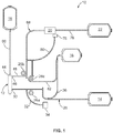
- Fig. 1 illustrates a disposable fluid flow circuit 10 having a membrane separator 12 (illustrated in greater detail as a spinning membrane separator 12a in Fig. 2 ) for use in combination with a durable, reusable separation system (which controls flow through the fluid flow circuit 10) to separate red blood cells from a red blood cell-containing fluid (e.g., anticoagulated whole blood).
- the disposable fluid flow circuit 10 and durable separation system may be similarly configured to the disposable fluid circuit and durable blood separation system described in PCT Patent Application Publication No. WO 2014/039086 A1 . While the following description may refer primarily to the separation of red blood cells from whole blood, it should be understood that the present disclosure is not limited to separation of red blood cells from whole blood, but may encompass separation of red blood cells from any red blood cell-containing fluid.
- the disposable fluid flow circuit 10 as illustrated in Fig. 1 includes various components interconnected by flow paths, which may be variously configured. In one embodiment, one or more of the flow paths between the components of the circuit 10 are defined by flexible plastic tubing, but the flow paths may be otherwise configured without departing from the scope of the present disclosure.
- the fluid flow circuit 10 is preferably fully pre-assembled and pre-sterilized, although certain components thereof (e.g., a fluid source container 14 and additive container 16) may be separately provided and sterilely connected to the circuit 10. More specifically, the illustrated disposable circuit 10 includes a fluid source container 14, an additive container 16, a membrane separator 12, a secondary fluid constituent collection container 18, a leukocyte reduction filter 20, and a red blood cell collection container 22.
- the circuit 10 may be associated with a separation system by connecting the membrane separator 12 to a separation actuator 24 of the separation system ( Fig. 2 ), while hanging the various containers from hangers or hooks of the separation system. It is also within the scope of the present disclosure for one or more of the containers to be associated with the separation system in a different way (e.g., by placing a container on a horizontal surface, such as a weigh scale). Also, pumps may be provided to control flow through the circuit 10. For example, certain portions of the flow path may be engaged by fluid pumps 26a-26c (e.g., peristaltic pumps) of the separation system, which cause the passage of fluid through the circuit 10. It should be understood that the illustrated circuit 10 is merely exemplary and that differently configured disposable fluid circuits having a membrane separator for separating red blood cells from a red blood cell-containing fluid may be employed without departing from the scope of the present disclosure.
- the fluid source container 14 may be any suitable container but is typically a flexible plastic pouch or bag in which a red blood cell-containing fluid (e.g., approximately 450 ml of whole blood) has been previously collected.
- the container 14 may be separate from the fluid circuit 10 during collection from a fluid source, allowing the red blood cell-containing fluid to be more easily collected and stored before being joined to the rest of the fluid circuit 10, or may be connected with the circuit 10 at the time of collection.
- the container 14 is provided with an amount of anticoagulant prior to (or following) the introduction of the red blood cell-containing fluid into the container 14 and before the anticoagulated fluid is flowed out of the container 14 to prevent premature coagulation.
- a flow path 28 (referred to herein as the "inlet flow path") is attached to the fluid source container 14, such as by a sterile connection device or other suitable attachment mechanism, and defines a fluid flow path from the container 14 to an inlet port 30 of the membrane separator 12.
- the inlet flow path 28 may include additional components (e.g., fluid control valves or clamps) and junctions and branches, such as a flow path branch 32 that may be associated with a pressure sensor 34 of the separation system and/or a flow path branch 36 that may be associated with the additive container 16.
- a portion of the inlet flow path 28 may be configured to be acted upon by an inlet pump 26a of the separation system for actively pumping fluid through the inlet flow path 28 and into the membrane separator 12.
- the configuration of the inlet pump 26a may vary without departing from the scope of the present disclosure, but in one embodiment it is provided as a peristaltic pump that operates by progressive compression or squeezing of a portion of the inlet flow path 28.
- Fig. 2 shows a particular embodiment of the membrane separator 12 in greater detail, along with a separation actuator 24 of the separation system.
- the separator 12a of Fig. 2 employs a membrane on a spinning rotor, and is referred to herein as a spinning membrane separator.
- the spinning membrane separator 12a includes a generally cylindrical housing 38, mounted concentrically about a longitudinal vertical central axis.
- An internal member or rotor 40 is mounted within the housing 38, preferably concentrically with the central axis.
- the rotor 40 is rotatable about the central axis, while the housing 38 remains stationary.
- the boundaries of the fluid flow path through the spinning membrane separator 12a are generally defined by the gap 42 between the interior surface of the housing 38 and the exterior surface of the rotor 40.
- the spacing between the housing 38 and the rotor 40 is sometimes referred to as the shear gap 42.
- a typical shear gap may be approximately 0.025 -0.050 inches wide and may be of a uniform dimension along the axis, for example, where the axis of the rotor 40 and housing 38 are coincident.
- the dimensions of the shear gap 42 may also vary circumferentially, for example, where the rotor 40 and the axis of the housing 38 are offset.
- the anticoagulated red blood cell-containing fluid is fed from the inlet flow path 28 into the housing 38 via an inlet port 30 ( Fig. 1 ), which directs the fluid into a fluid flow entrance region in a path tangential to and in fluid communication with the shear gap 42.
- the housing 38 At an axial end of the cylindrical housing 38 (preferably the end spaced farthest from the inlet port 30), the housing 38 includes an axial outlet port 44 for withdrawal of a secondary fluid constituent (i.e., the fluid component separated from the red blood cells) from the spinning membrane separator 12a.
- the spinning membrane separator 12a is oriented to position the axial outlet port 44 at the bottom end of the spinning membrane separator 12a, while Fig.
- membrane separator 12 oriented to position the axial outlet port 44 at the upper end. It should be understood that different membrane separators may be oriented differently such that, depending on the design of the membrane separator and associated separation system, the membrane separator may be connected to the separation system so as to orient the axial outlet port 44 in any direction without departing from the scope of the present disclosure.
- the housing 38 Adjacent to the axial end of the housing 38 having the axial outlet port 44, the housing 38 also has a side or tangential or red blood cell outlet port 46 ( Fig. 1 ) that communicates with the gap 42 between the housing 38 and rotor 40 ( Fig. 2 ) and with a concentrated red cell flow path flow path 48 ( Fig. 1 ) for withdrawing concentrated red blood cells from the separator gap 42.
- the axial end of the cylindrical housing 38 opposite the axial outlet port 44 may include an end cap 50.
- the end cap 50 is configured to be at least partially received within the separation actuator 24 of the separation system ( Fig. 2 ) to allow the separation actuator 24 to rotate the rotor 40, as will be described in greater detail.
- the rotor 40 is rotatably mounted between the axial ends of the housing 38 and may be provided as a generally cylindrical central mandrel 52, the outer surface of which is shaped to define a series of spaced-apart circumferential grooves or ribs separated by annular lands.
- the surface channels defined by the circumferential grooves are interconnected by longitudinal grooves. At each end of the mandrel 52, these grooves are in communication with a central orifice or manifold 54.
- the surface of the rotor 40 is at least partially (and more preferably substantially or entirely) covered by a cylindrical porous membrane 56.
- the nominal pore size of the membrane 56 may vary, but it may be preferred for the membrane 56 to be configured (including having suitable nominal pore size) to allow plasma (or some other fluid constituent to be separated from red blood cells) to pass through the membrane 56 without allowing the passage of red blood cells therethrough.
- a membrane could potentially be mounted on the inside surface of the housing 38, facing the gap 42 between the inside surface of the housing wall and the outer surface of the rotor 40, or a membrane could be carried on both the outer surface of the rotor 40 and the inner surface of the housing 38 so that plasma flows through both membranes simultaneously, therefore potentially increasing the separation speed or performance of the spinning membrane separator 12a.
- the rotor 40 is mounted in the end cap 50 to rotate about a pin 58, which is press fit into the end cap 50 on one side and seated within a cylindrical bearing surface in an end cylinder 60 forming part of the rotor 40.
- the rotor 40 may be rotated by any suitable rotary drive device or system, but in the illustrated embodiment, the end cylinder 60 includes or is partially formed of a magnetic material utilized in indirect driving of the rotor 40.
- the separation actuator 24 of the separation system includes a drive motor 62 exterior to the housing 38, which is coupled to turn an annular magnetic drive member 64 that includes a magnetic material that is attracted to the magnetic material of the end cylinder 60. As the annular drive member 64 is rotated, magnetic attraction between the end cylinder 60 and the annular drive member 64 effectively locks the rotor 40 to the exterior drive, causing the rotor 40 to rotate.
- Rotation of the rotor 40 while fluid is present within the housing 38 causes Taylor vortices to arise in the gap 42.
- the Taylor vortices help to prevent cellular fluid components (e.g., red blood cells) from fouling or clogging the membrane 56, while encouraging smaller diameter fluid constituents (e.g., plasma) to pass through the pores of the membrane 56 to reach the central orifice or manifold 54.
- the axial outlet port 44 communicates with the central orifice 54, such that the fluid constituents (e.g., plasma) passing through the membrane 56 and into the central orifice 54 may be transported to the axial outlet port 44.
- the concentrated red blood cells flow through the tangential outlet port 48 communicating with the gap 42 between the rotor 40 and the housing 38 and through a red blood cell flow path 48, which forms part of an outlet flow path 68.
- the separated red blood cells may be pumped through the outlet flow path 68 under action of a red blood cell or outlet pump 26b of the blood separation system.
- the outlet pump 26b may be configured and operate substantially the same as the inlet pump 26a or it may be differently configured (e.g., as a flexible diaphragm pump) without departing from the scope of the present disclosure. It will be seen that there is no pump associated with the secondary fluid constituent flow path 66, as the volumetric flow rate therethrough is instead equal to the difference between the volumetric flow rate of the inlet pump 26a and the volumetric flow rate of the outlet pump 26b.
- red blood cell-containing fluid pumped into the membrane separator 12 is whole blood, then the membrane separator 12 will function to separate the blood into concentrated red blood cells and virtually cell free plasma. Packed red blood cells at approximately 80-85% hematocrit will be pumped out of the separator 12 through the red blood cell flow path 48. If the red blood cell-containing fluid is different from whole blood, then the nature of the separated red blood cells (e.g., their hematocrit) and the nature of the other fluid constituent from which the red blood cells are separated may vary.
- the disposable fluid flow circuit 10 includes a leukocyte reduction filter or leukoreduction filter 20, which may be of any suitable well known construction for removing leukocytes from concentrated red blood cells without unduly causing hemolysis of red blood cells or reducing the number of red blood cells in the collected product.
- a leukocyte reduction filter or leukoreduction filter 20 may be of any suitable well known construction for removing leukocytes from concentrated red blood cells without unduly causing hemolysis of red blood cells or reducing the number of red blood cells in the collected product.
- suitable leukocyte reduction filters may be found in U.S. Patent Application Serial Nos. 14/222,961 ; 14/223,511 ; and 14/223,831 .
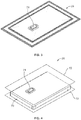
- Figs. 3 and 4 illustrate an exemplary leukoreduction filter 20, which includes a filter medium 70 positioned between two flexible walls 72 ( Fig. 4 ), which are sealed together to prevent leakage of fluid passing through the filter 20.
- the filter 20 is associated with the outlet flow path 68, with the separated red blood cells flowing out of the membrane separator 12, through the red blood cell flow path 48 of the outlet flow path 68, and into the leukoreduction filter 20.
- the red blood cells pass from an inlet 74 of the leukoreduction filter 20 to an outlet (not illustrated), passing through the filter medium 70, which removes leukocytes from the red blood cells.
- the concentrated red blood cells flow through a continuation 76 of the outlet flow path 68 into a storage container 22, which may be of any suitable material compatible with red blood cell storage.
- the force of the pump 26b pushing the concentrated red blood cells through the filter 20 helps to maintain and limit the processing time within a reasonable range, as compared, for example, to the time that would be required for gravity flow of concentrated red blood cells through a leukocyte reduction filter in a manual setting. While Fig. 5 shows the pump 26b positioned upstream of the leukoreduction filter 20, it should be understood that the pump 26b may also be positioned downstream of the leukoreduction filter 20 (i.e., between the leukoreduction filter 20 and the storage container 22). If the leukoreduction filter 20 is formed with flexible walls 72 (as illustrated in Figs.
- the outlet pump 26b may be controlled to operate to the point of causing the walls 72 to collapse, which better provides that all of the separated blood cells are flowed to the storage container 22 rather than being entrapped within the filter 20.
- a pressure sensor 78 associated with the outlet flow path 68 e.g., associated via flow path branch 80
- the outlet flow path 68 may include additional components (e.g., valves or clamps) and junctions and branches, such as an additive junction and flow path branch 82, which leads to a red blood cell storage solution or additive container 16.
- the container 16 may include a storage solution or additive that may be pumped into the outlet flow path 68 by operation of an additive pump 26c of the separation system for addition to separated red blood cells in the storage container 22.
- the pressure sensors 34 and 78 associated with the inlet flow path 28 and outlet flow path 68 may function to monitor the pressure within the associated flow path and send signals to a controller of the separation system that are indicative of the pressure within the flow path or paths being monitored. If the controller determines that an improper pressure is present within the fluid flow circuit 10 (e.g., a high pressure due to an occlusion of one of the flow paths), then the controller may instruct one or more of the pumps 26a-26c and/or one or more of the clamps or valves associated with the fluid flow circuit 10 to act so as to alleviate the improper pressure condition (e.g., by reversing the direction of operation of one of the pumps 26a-26c and/or opening or closing one of the clamps or valves). Additional or alternative pressure sensors may also be provided without departing from the scope of the present disclosure.
- Fig. 5 illustrates a variation of the fluid flow circuit 10 of Fig. 1 .
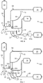
- the fluid flow circuit 10a of Fig. 5 differs principally from the fluid flow circuit 10 of Fig. 1 in that the outlet flow path 68 includes a microaggregate filter 84 positioned directly upstream of the leukoreduction filter 20 (i.e., between the red blood cell outlet port 46 of the membrane separator 12 and the inlet 74 of the leukoreduction filter 20).
- the configuration of the microaggregate filter 84 may vary without departing from the scope of the present disclosure (and will typically vary based on the nature and configuration of the leukoreduction filter 20 to better match the leukoreduction filter 20), but in one embodiment it may be provided as a filter sock having a length of approximately four inches and a pore size of approximately 80 microns.
- the configuration of the microaggregate filter 84 (e.g., the pore size) may also vary depending on the nature of the red blood cell-containing fluid, as microaggregates of differing diameters may be expected to arise from different fluids.
- microaggregate filter 84 By positioning the microaggregate filter 84 upstream of the leukoreduction filter 20, larger particles (e.g., microaggregates) are prevented from reaching and potentially clogging or impeding flow through the leukoreduction filter 20. Accordingly, the addition of a microaggregate filter 84 may have the effect of increasing the rate at which separated red blood cells pass through the leukoreduction filter 20, while also ensuring that a higher percentage of the red blood cells pass through the leukoreduction filter 20 without becoming entrapped therein.
- Fig. 6 illustrates another variation of the fluid flow circuit 10 of Fig. 1 .
- the fluid flow circuit 10b of Fig. 6 differs principally from the fluid flow circuit 10 of Fig. 1 in that the leukoreduction filter 20 is absent from the outlet flow path 68, with a leukoreduction filter 20a instead being associated with the inlet flow path 28.
- the filter medium of the leukoreduction filter 20a may be configured to provide leukocyte reduction of anticoagulated red blood cell-containing fluid (e.g., anticoagulated whole blood), rather than separated red blood cells.
- anticoagulated red blood cell-containing fluid e.g., anticoagulated whole blood
- its hematocrit and viscosity are typically less than the hematocrit and viscosity of the separated red blood cells passed through the leukoreduction filter 20 in the embodiment of Figs.
- the leukoreduction filter 20a may be associated with the inlet flow path 28 in various locations without departing from the scope of the present disclosure.
- Fig. 6 illustrates a leukoreduction filter 20a positioned upstream of the portion of the inlet flow path 28 configured to be acted upon by the inlet pump 26a of the separation system (i.e., between the inlet pump 26a and the fluid source container 14).
- a leukoreduction filter 20a is positioned downstream of the portion of the inlet flow path 28 configured to be acted upon by the inlet pump 26a of the separation system (i.e., between the inlet pump 26a and the membrane separator 12).
- One possible advantage of positioning the leukoreduction filter 20a upstream of the inlet pump 26a is to provide a clearer path between the inlet pump 26a and the membrane separator 12.
- optimized performance of the system may be controlled in part by monitoring pressure within the inlet flow path 28 (e.g., using a pressure sensor 34 associated with the inlet flow path 28 by branch 32).
- a leukoreduction filter 20a positioned upstream of the pump 26a avoids any pressure disruption between the pump 26a and the membrane separator 12, thereby possibly making it easier to precisely measure the pressure within the inlet flow path 28.
- the fluid flow circuit 10b, 10c may also include a microaggregate filter 84a positioned upstream of the leukoreduction filter 20a, as described above with respect to the embodiment of Fig. 5 .
- the inlet pump 26a may be controlled to operate to the point of causing the walls to collapse, which better ensures that all of the anticoagulated red blood cell-containing fluid is flowed to the membrane separator 12 rather than being entrapped within the filter 20a. If provided, a pressure sensor 34 associated with the inlet flow path 28 may wait for a particular pressure reading or condition (indicative of filter collapse) before signaling, via a controller (not shown), for cessation of operation of the inlet pump 26a.
- the inlet pump 26a may be controlled to operate until the fluid source container 14 has been emptied of the red blood cell-containing fluid (which may be confirmed by a weigh scale associated with the fluid source container 14 or an optical monitor associated with the inlet flow path 28 or by any other suitable approach) and then operate for an additional amount of time after the fluid source container 14 has been emptied for improved filter volume recovery.
Landscapes
- Health & Medical Sciences (AREA)
- Heart & Thoracic Surgery (AREA)
- Engineering & Computer Science (AREA)
- Life Sciences & Earth Sciences (AREA)
- Biomedical Technology (AREA)
- Vascular Medicine (AREA)
- Hematology (AREA)
- General Health & Medical Sciences (AREA)
- Animal Behavior & Ethology (AREA)
- Public Health (AREA)
- Veterinary Medicine (AREA)
- Anesthesiology (AREA)
- Urology & Nephrology (AREA)
- Wood Science & Technology (AREA)
- Zoology (AREA)
- Organic Chemistry (AREA)
- Biotechnology (AREA)
- Bioinformatics & Cheminformatics (AREA)
- Genetics & Genomics (AREA)
- Chemical & Material Sciences (AREA)
- Emergency Medicine (AREA)
- Cardiology (AREA)
- Cell Biology (AREA)
- Microbiology (AREA)
- Biochemistry (AREA)
- General Engineering & Computer Science (AREA)
- Immunology (AREA)
- External Artificial Organs (AREA)
Description
- This application claims the benefit of and priority of
U.S. Patent Application Serial No. 14/677,319, filed April 2, 2015 - The invention relates to blood separation systems and methods. More particularly, the invention relates to blood separation systems and methods also involving leukoreduction of the blood or of a separated cellular blood component.
- Traditional blood collection continues to rely heavily on manual collection of whole blood from healthy donors through blood drives, from donor visits to blood centers or hospitals and the like. In typical manual collection, whole blood is collected by simply flowing it, under the force of gravity and venous pressure, from the vein of the donor into a collection container. The amount of whole blood drawn is typically a "unit," which is about 450 ml.
- More specifically, such a collection typically employs a pre-assembled arrangement of tubing and containers or bags, including a flexible plastic primary container or bag for receiving a unit of whole blood from a donor and one or more "satellite" containers or bags. The blood is first collected in the primary container, which also contains an anticoagulant (typically, but not exclusively, containing sodium citrate, phosphate, and dextrose - often referred to as CPD). A preservative (often called an "additive solution" or AS, and commonly containing a saline, adenine, and glucose medium - which is referred to as SAG) may be included as part of a larger assembly of bags and tubes that are used in processing after the blood is collected.
- After collection of a unit of whole blood, it is common practice in blood banking to transport the unit of whole blood, with connected tubing and containers, to a blood component processing laboratory, commonly referred to as a "back lab," for further processing. Further processing usually entails manually loading the primary container and associated tubing and satellite containers into a centrifuge to separate the whole blood into components such as concentrated red cells and platelet-rich or platelet-poor plasma. These components are then manually expressed from the primary container into other pre-connected satellite containers, and may be again centrifuged to separate the platelets from plasma. Subsequently, the blood components may be leukoreduced (i.e., have the white blood cells or leukocytes contained therein removed) by filtration for further processing or storage. In short, this process is time consuming, labor intensive, and subject to possible human error.
- While many of the prior blood separation apparatus and procedures have employed centrifugal separation principles, there is another class of devices that employs relatively rotating surfaces, at least one of which carries a porous membrane. Typically the device employs an outer stationary housing and an internal spinning rotor covered by a porous membrane. Detailed descriptions of membrane separators may be found in
U.S. Patents Nos. 5,194,145 ;4,776,964 ;4,753,729 ; and5,135,667 . - Such systems may include a membrane-covered spinner having an interior collection system disposed within a stationary shell or housing. Alternatively, an inner surface of the stationary housing may be covered by a membrane, or both the spinner and the housing may include associated membranes. For purposes of this description, these will be referred to as membrane separators. In such membrane separators, blood is fed into an annular space or gap between the spinner and the shell and moves along the longitudinal axis of the shell toward an exit region. Plasma passes through the membrane and exits through an outlet port, while the remaining cellular blood components (red blood cells, platelets, and white cells) remain in the gap and move to the exit region between the spinner and the shell. Membrane separators have been found to provide excellent plasma filtration rates, due primarily to the unique flow patterns ("Taylor vortices") induced in the gap between the spinning membrane and the shell. The Taylor vortices help to keep the blood cells from depositing on and fouling or clogging the membrane.
- While membrane separators have been widely used for the collection of plasma, they have not typically been used for the collection of other blood components, specifically red blood cells. One example of a membrane separator used in the collection of separated red blood cells is described in
PCT Patent Application Publication No. WO 2014/039086 A1 . Further prior art includesWO2012/125457 A1 andWO2014/016198 A1 . - The subject matter disclosed herein provides further advances in membrane separators, particularly in terms of the reduction of leukocytes in a final collected cellular blood component.
- The invention is defined by the appended claims. There are several aspects of the present subject matter which may be embodied separately or together in the devices, systems, and methods described and/or claimed below. These aspects may be employed alone or in combination with other aspects of the subject matter described herein, and the description of these aspects together is not intended to preclude the use of these aspects separately.
- In one aspect, a fluid flow circuit is provided for separating an anticoagulated red blood cell-containing fluid into separated red blood cells and another fluid constituent. The fluid flow circuit includes a spinning membrane separator including an inlet port and a red blood cell outlet port and configured to separate an anticoagulated red blood cell-containing fluid into separated red blood cells and another fluid constituent. An inlet flow path is in fluid communication with the inlet port and a fluid source container for flowing anticoagulated red blood cell-containing fluid from the fluid source container to the inlet port, with a leukoreduction filter being associated with the inlet flow path and positioned stream of the spinning membrane separator.
- In another aspect, a method is provided for separating an anticoagulated red blood cell-containing fluid into separated red blood cells and another fluid constituent. The method involves providing an anticoagulated red blood cell-containing fluid and flowing it through an inlet flow path, into a spinning membrane separator. The anticoagulated red blood cell-containing fluid is separated into separated red blood cells and another fluid constituent, and the separated red blood cells are flowed out of the membrane separator via an outlet flow path. Prior to the anticoagulated red blood cell-containing fluid entering the membrane separator, it is leukoreduced by passing it through a leukocyte reduction filter associated with the inlet flow path.
- In yet another aspect not forming part of the invention claimed, a fluid flow circuit is provided for separating a red blood cell-containing fluid into separated red blood cells and another fluid constituent. The fluid flow circuit includes a membrane separator having an inlet port and a red blood cell outlet port. An inlet flow path is in fluid communication with the inlet port and an outlet flow path is associated with the red blood cell outlet port, with a leukoreduction filter being associated with the outlet flow path. A microaggregate filter is positioned between the red blood cell outlet port and the leukoreduction filter.
- In another aspect not forming part of the invention claimed, a method is provided for separating a red blood cell-containing fluid into separated red blood cells and another fluid constituent. The method involves providing a red blood cell-containing fluid and flowing it through an inlet flow path, into a membrane separator. The red blood cell-containing fluid is separated into separated red blood cells and another fluid constituent, and the separated red blood cells are flowed out of the membrane separator via an outlet flow path, with the separated red blood cells passing through a microaggregate filter and a leukoreduction filter.
-
-
Fig. 1 is a front elevational view of an exemplary disposable fluid flow circuit according to an aspect of the present disclosure; -
Fig. 2 is a perspective view of a membrane separator of the fluid flow circuit ofFig. 1 , in partial cross section and with portions removed to show detail; -
Fig. 3 is a front perspective view of a flexible luekoreduction filter of the fluid flow circuit ofFig. 1 ; -
Fig. 4 is an exploded perspective view of the leukoreduction filter ofFig. 3 ; and -
Figs. 5-7 are front elevational views of other embodiments of an exemplary disposable fluid flow circuit according to an aspect of the present disclosure. - The embodiments disclosed herein are for the purpose of providing an exemplary description of the present subject matter. They are, however, only exemplary and not exclusive, and the present subject matter may be embodied in various forms. Therefore, specific details disclosed herein are not to be interpreted as limiting the subject matter as defined in the accompanying claims.
-
Fig. 1 illustrates a disposablefluid flow circuit 10 having a membrane separator 12 (illustrated in greater detail as aspinning membrane separator 12a inFig. 2 ) for use in combination with a durable, reusable separation system (which controls flow through the fluid flow circuit 10) to separate red blood cells from a red blood cell-containing fluid (e.g., anticoagulated whole blood). The disposablefluid flow circuit 10 and durable separation system may be similarly configured to the disposable fluid circuit and durable blood separation system described inPCT Patent Application Publication No. WO 2014/039086 A1 . While the following description may refer primarily to the separation of red blood cells from whole blood, it should be understood that the present disclosure is not limited to separation of red blood cells from whole blood, but may encompass separation of red blood cells from any red blood cell-containing fluid. - The disposable
fluid flow circuit 10 as illustrated inFig. 1 includes various components interconnected by flow paths, which may be variously configured. In one embodiment, one or more of the flow paths between the components of thecircuit 10 are defined by flexible plastic tubing, but the flow paths may be otherwise configured without departing from the scope of the present disclosure. Thefluid flow circuit 10 is preferably fully pre-assembled and pre-sterilized, although certain components thereof (e.g., afluid source container 14 and additive container 16) may be separately provided and sterilely connected to thecircuit 10. More specifically, the illustrateddisposable circuit 10 includes afluid source container 14, anadditive container 16, amembrane separator 12, a secondary fluidconstituent collection container 18, aleukocyte reduction filter 20, and a red bloodcell collection container 22. Thecircuit 10 may be associated with a separation system by connecting themembrane separator 12 to aseparation actuator 24 of the separation system (Fig. 2 ), while hanging the various containers from hangers or hooks of the separation system. It is also within the scope of the present disclosure for one or more of the containers to be associated with the separation system in a different way (e.g., by placing a container on a horizontal surface, such as a weigh scale). Also, pumps may be provided to control flow through thecircuit 10. For example, certain portions of the flow path may be engaged byfluid pumps 26a-26c (e.g., peristaltic pumps) of the separation system, which cause the passage of fluid through thecircuit 10. It should be understood that the illustratedcircuit 10 is merely exemplary and that differently configured disposable fluid circuits having a membrane separator for separating red blood cells from a red blood cell-containing fluid may be employed without departing from the scope of the present disclosure. - The
fluid source container 14 may be any suitable container but is typically a flexible plastic pouch or bag in which a red blood cell-containing fluid (e.g., approximately 450 ml of whole blood) has been previously collected. Thecontainer 14 may be separate from thefluid circuit 10 during collection from a fluid source, allowing the red blood cell-containing fluid to be more easily collected and stored before being joined to the rest of thefluid circuit 10, or may be connected with thecircuit 10 at the time of collection. Preferably, thecontainer 14 is provided with an amount of anticoagulant prior to (or following) the introduction of the red blood cell-containing fluid into thecontainer 14 and before the anticoagulated fluid is flowed out of thecontainer 14 to prevent premature coagulation. - A flow path 28 (referred to herein as the "inlet flow path") is attached to the
fluid source container 14, such as by a sterile connection device or other suitable attachment mechanism, and defines a fluid flow path from thecontainer 14 to aninlet port 30 of themembrane separator 12. Theinlet flow path 28 may include additional components (e.g., fluid control valves or clamps) and junctions and branches, such as aflow path branch 32 that may be associated with apressure sensor 34 of the separation system and/or aflow path branch 36 that may be associated with theadditive container 16. - Additionally, it may be preferred for a portion of the
inlet flow path 28 to be configured to be acted upon by aninlet pump 26a of the separation system for actively pumping fluid through theinlet flow path 28 and into themembrane separator 12. The configuration of theinlet pump 26a may vary without departing from the scope of the present disclosure, but in one embodiment it is provided as a peristaltic pump that operates by progressive compression or squeezing of a portion of theinlet flow path 28. -
Fig. 2 shows a particular embodiment of themembrane separator 12 in greater detail, along with aseparation actuator 24 of the separation system. Theseparator 12a ofFig. 2 employs a membrane on a spinning rotor, and is referred to herein as a spinning membrane separator. The spinningmembrane separator 12a includes a generallycylindrical housing 38, mounted concentrically about a longitudinal vertical central axis. An internal member or rotor 40 is mounted within thehousing 38, preferably concentrically with the central axis. The rotor 40 is rotatable about the central axis, while thehousing 38 remains stationary. The boundaries of the fluid flow path through the spinningmembrane separator 12a are generally defined by thegap 42 between the interior surface of thehousing 38 and the exterior surface of the rotor 40. The spacing between thehousing 38 and the rotor 40 is sometimes referred to as theshear gap 42. A typical shear gap may be approximately 0.025 -0.050 inches wide and may be of a uniform dimension along the axis, for example, where the axis of the rotor 40 andhousing 38 are coincident. The dimensions of theshear gap 42 may also vary circumferentially, for example, where the rotor 40 and the axis of thehousing 38 are offset. - The anticoagulated red blood cell-containing fluid is fed from the
inlet flow path 28 into thehousing 38 via an inlet port 30 (Fig. 1 ), which directs the fluid into a fluid flow entrance region in a path tangential to and in fluid communication with theshear gap 42. At an axial end of the cylindrical housing 38 (preferably the end spaced farthest from the inlet port 30), thehousing 38 includes anaxial outlet port 44 for withdrawal of a secondary fluid constituent (i.e., the fluid component separated from the red blood cells) from the spinningmembrane separator 12a. In the orientation ofFig. 2 , the spinningmembrane separator 12a is oriented to position theaxial outlet port 44 at the bottom end of the spinningmembrane separator 12a, whileFig. 1 shows themembrane separator 12 oriented to position theaxial outlet port 44 at the upper end. It should be understood that different membrane separators may be oriented differently such that, depending on the design of the membrane separator and associated separation system, the membrane separator may be connected to the separation system so as to orient theaxial outlet port 44 in any direction without departing from the scope of the present disclosure. - Adjacent to the axial end of the
housing 38 having theaxial outlet port 44, thehousing 38 also has a side or tangential or red blood cell outlet port 46 (Fig. 1 ) that communicates with thegap 42 between thehousing 38 and rotor 40 (Fig. 2 ) and with a concentrated red cell flow path flow path 48 (Fig. 1 ) for withdrawing concentrated red blood cells from theseparator gap 42. The axial end of thecylindrical housing 38 opposite theaxial outlet port 44 may include anend cap 50. Theend cap 50 is configured to be at least partially received within theseparation actuator 24 of the separation system (Fig. 2 ) to allow theseparation actuator 24 to rotate the rotor 40, as will be described in greater detail. - The rotor 40 is rotatably mounted between the axial ends of the
housing 38 and may be provided as a generally cylindricalcentral mandrel 52, the outer surface of which is shaped to define a series of spaced-apart circumferential grooves or ribs separated by annular lands. The surface channels defined by the circumferential grooves are interconnected by longitudinal grooves. At each end of themandrel 52, these grooves are in communication with a central orifice ormanifold 54. - In the illustrated embodiment, the surface of the rotor 40 is at least partially (and more preferably substantially or entirely) covered by a cylindrical
porous membrane 56. The nominal pore size of themembrane 56 may vary, but it may be preferred for themembrane 56 to be configured (including having suitable nominal pore size) to allow plasma (or some other fluid constituent to be separated from red blood cells) to pass through themembrane 56 without allowing the passage of red blood cells therethrough. While the illustrated embodiment places themembrane 56 on the rotor 40, it should be recognized that a membrane could potentially be mounted on the inside surface of thehousing 38, facing thegap 42 between the inside surface of the housing wall and the outer surface of the rotor 40, or a membrane could be carried on both the outer surface of the rotor 40 and the inner surface of thehousing 38 so that plasma flows through both membranes simultaneously, therefore potentially increasing the separation speed or performance of the spinningmembrane separator 12a. - The rotor 40 is mounted in the
end cap 50 to rotate about apin 58, which is press fit into theend cap 50 on one side and seated within a cylindrical bearing surface in anend cylinder 60 forming part of the rotor 40. The rotor 40 may be rotated by any suitable rotary drive device or system, but in the illustrated embodiment, theend cylinder 60 includes or is partially formed of a magnetic material utilized in indirect driving of the rotor 40. Theseparation actuator 24 of the separation system includes adrive motor 62 exterior to thehousing 38, which is coupled to turn an annularmagnetic drive member 64 that includes a magnetic material that is attracted to the magnetic material of theend cylinder 60. As theannular drive member 64 is rotated, magnetic attraction between theend cylinder 60 and theannular drive member 64 effectively locks the rotor 40 to the exterior drive, causing the rotor 40 to rotate. - Rotation of the rotor 40 while fluid is present within the
housing 38 causes Taylor vortices to arise in thegap 42. The Taylor vortices help to prevent cellular fluid components (e.g., red blood cells) from fouling or clogging themembrane 56, while encouraging smaller diameter fluid constituents (e.g., plasma) to pass through the pores of themembrane 56 to reach the central orifice ormanifold 54. At the axial end of the rotor 40 opposite theend cap 50, theaxial outlet port 44 communicates with thecentral orifice 54, such that the fluid constituents (e.g., plasma) passing through themembrane 56 and into thecentral orifice 54 may be transported to theaxial outlet port 44. As for the fluid constituents that do not pass through themembrane 56, they travel along the length of thegap 42 from the inlet port 30 (positioned adjacent to one axial end of the rotor 40) to the tangential or red blood cell outlet port 46 (positioned adjacent to the other axial end of the rotor 40). Additional details concerning the design and functionality of a membrane separator that is suitable for the separation and collection of red blood cells may be found inPCT Patent Application Publication No. WO 2014/039086 A1 - The small-diameter fluid constituent (referred to herein as the "secondary fluid constituent," which may include plasma, but is not limited to plasma) separated by the
membrane separator 12 flows from theaxial outlet port 44, through a secondary fluidconstituent flow path 66, and into astorage container 18, which may be of any suitable material compatible with storage of the secondary fluid constituent. Similarly, from themembrane separator 12, the concentrated red blood cells flow through thetangential outlet port 48 communicating with thegap 42 between the rotor 40 and thehousing 38 and through a red bloodcell flow path 48, which forms part of anoutlet flow path 68. The separated red blood cells may be pumped through theoutlet flow path 68 under action of a red blood cell oroutlet pump 26b of the blood separation system. Theoutlet pump 26b may be configured and operate substantially the same as theinlet pump 26a or it may be differently configured (e.g., as a flexible diaphragm pump) without departing from the scope of the present disclosure. It will be seen that there is no pump associated with the secondary fluidconstituent flow path 66, as the volumetric flow rate therethrough is instead equal to the difference between the volumetric flow rate of theinlet pump 26a and the volumetric flow rate of theoutlet pump 26b. - If the red blood cell-containing fluid pumped into the
membrane separator 12 is whole blood, then themembrane separator 12 will function to separate the blood into concentrated red blood cells and virtually cell free plasma. Packed red blood cells at approximately 80-85% hematocrit will be pumped out of theseparator 12 through the red bloodcell flow path 48. If the red blood cell-containing fluid is different from whole blood, then the nature of the separated red blood cells (e.g., their hematocrit) and the nature of the other fluid constituent from which the red blood cells are separated may vary. - For reducing the number of leukocytes that may be present in the separated red blood cells, the disposable
fluid flow circuit 10 includes a leukocyte reduction filter orleukoreduction filter 20, which may be of any suitable well known construction for removing leukocytes from concentrated red blood cells without unduly causing hemolysis of red blood cells or reducing the number of red blood cells in the collected product. Examples of suitable leukocyte reduction filters may be found inU.S. Patent Application Serial Nos. 14/222,961 ;14/223,511 14/223,831 Figs. 3 and 4 illustrate anexemplary leukoreduction filter 20, which includes afilter medium 70 positioned between two flexible walls 72 (Fig. 4 ), which are sealed together to prevent leakage of fluid passing through thefilter 20. In the embodiment ofFig. 1 , thefilter 20 is associated with theoutlet flow path 68, with the separated red blood cells flowing out of themembrane separator 12, through the red bloodcell flow path 48 of theoutlet flow path 68, and into theleukoreduction filter 20. The red blood cells pass from aninlet 74 of theleukoreduction filter 20 to an outlet (not illustrated), passing through thefilter medium 70, which removes leukocytes from the red blood cells. After exiting thefilter 20, the concentrated red blood cells flow through acontinuation 76 of theoutlet flow path 68 into astorage container 22, which may be of any suitable material compatible with red blood cell storage. - The force of the
pump 26b pushing the concentrated red blood cells through thefilter 20 helps to maintain and limit the processing time within a reasonable range, as compared, for example, to the time that would be required for gravity flow of concentrated red blood cells through a leukocyte reduction filter in a manual setting. WhileFig. 5 shows thepump 26b positioned upstream of theleukoreduction filter 20, it should be understood that thepump 26b may also be positioned downstream of the leukoreduction filter 20 (i.e., between theleukoreduction filter 20 and the storage container 22). If theleukoreduction filter 20 is formed with flexible walls 72 (as illustrated inFigs. 3 and 4 ), theoutlet pump 26b may be controlled to operate to the point of causing thewalls 72 to collapse, which better provides that all of the separated blood cells are flowed to thestorage container 22 rather than being entrapped within thefilter 20. If provided, apressure sensor 78 associated with the outlet flow path 68 (e.g., associated via flow path branch 80) may wait for a particular pressure reading or condition (indicative of filter collapse) before ceasing operation of theoutlet pump 26b. - The
outlet flow path 68 may include additional components (e.g., valves or clamps) and junctions and branches, such as an additive junction and flowpath branch 82, which leads to a red blood cell storage solution oradditive container 16. Thecontainer 16 may include a storage solution or additive that may be pumped into theoutlet flow path 68 by operation of anadditive pump 26c of the separation system for addition to separated red blood cells in thestorage container 22. - If provided, the
pressure sensors inlet flow path 28 andoutlet flow path 68, respectively, may function to monitor the pressure within the associated flow path and send signals to a controller of the separation system that are indicative of the pressure within the flow path or paths being monitored. If the controller determines that an improper pressure is present within the fluid flow circuit 10 (e.g., a high pressure due to an occlusion of one of the flow paths), then the controller may instruct one or more of thepumps 26a-26c and/or one or more of the clamps or valves associated with thefluid flow circuit 10 to act so as to alleviate the improper pressure condition (e.g., by reversing the direction of operation of one of thepumps 26a-26c and/or opening or closing one of the clamps or valves). Additional or alternative pressure sensors may also be provided without departing from the scope of the present disclosure. -
Fig. 5 illustrates a variation of thefluid flow circuit 10 ofFig. 1 . Thefluid flow circuit 10a ofFig. 5 differs principally from thefluid flow circuit 10 ofFig. 1 in that theoutlet flow path 68 includes amicroaggregate filter 84 positioned directly upstream of the leukoreduction filter 20 (i.e., between the red bloodcell outlet port 46 of themembrane separator 12 and theinlet 74 of the leukoreduction filter 20). The configuration of themicroaggregate filter 84 may vary without departing from the scope of the present disclosure (and will typically vary based on the nature and configuration of theleukoreduction filter 20 to better match the leukoreduction filter 20), but in one embodiment it may be provided as a filter sock having a length of approximately four inches and a pore size of approximately 80 microns. The configuration of the microaggregate filter 84 (e.g., the pore size) may also vary depending on the nature of the red blood cell-containing fluid, as microaggregates of differing diameters may be expected to arise from different fluids. By positioning themicroaggregate filter 84 upstream of theleukoreduction filter 20, larger particles (e.g., microaggregates) are prevented from reaching and potentially clogging or impeding flow through theleukoreduction filter 20. Accordingly, the addition of amicroaggregate filter 84 may have the effect of increasing the rate at which separated red blood cells pass through theleukoreduction filter 20, while also ensuring that a higher percentage of the red blood cells pass through theleukoreduction filter 20 without becoming entrapped therein. -
Fig. 6 illustrates another variation of thefluid flow circuit 10 ofFig. 1 . Thefluid flow circuit 10b ofFig. 6 differs principally from thefluid flow circuit 10 ofFig. 1 in that theleukoreduction filter 20 is absent from theoutlet flow path 68, with aleukoreduction filter 20a instead being associated with theinlet flow path 28. As the nature of the fluid passing through theleukoreduction filter 20a (when positioned upstream of the membrane separator 12) is different from the nature of the fluid passing through the leukoreduction filter 20 (when positioned downstream of the membrane separator 12), the filter medium of theleukoreduction filter 20a may be configured to provide leukocyte reduction of anticoagulated red blood cell-containing fluid (e.g., anticoagulated whole blood), rather than separated red blood cells. Regardless of the nature of the red blood cell-containing fluid, its hematocrit and viscosity are typically less than the hematocrit and viscosity of the separated red blood cells passed through theleukoreduction filter 20 in the embodiment ofFigs. 1 and5 , meaning that decreased filtration time and incidence of clogging and/or fouling of the leukoreduction filter may be expected when positioning theleukoreduction filter 20a upstream of themembrane separator 12 instead of downstream. This may be especially advantageous when the anticoagulated red blood cell-containing fluid has been stored in thefluid source container 14 for an extended amount of time (e.g., up to three days or longer) prior to processing. - The
leukoreduction filter 20a may be associated with theinlet flow path 28 in various locations without departing from the scope of the present disclosure. For example,Fig. 6 illustrates aleukoreduction filter 20a positioned upstream of the portion of theinlet flow path 28 configured to be acted upon by theinlet pump 26a of the separation system (i.e., between theinlet pump 26a and the fluid source container 14). In another embodiment of a fluid flow circuit 10c, which is shown inFig. 7 , aleukoreduction filter 20a is positioned downstream of the portion of theinlet flow path 28 configured to be acted upon by theinlet pump 26a of the separation system (i.e., between theinlet pump 26a and the membrane separator 12). One possible advantage of positioning theleukoreduction filter 20a upstream of theinlet pump 26a (as shown inFig. 6 ) is to provide a clearer path between theinlet pump 26a and themembrane separator 12. In particular, optimized performance of the system may be controlled in part by monitoring pressure within the inlet flow path 28 (e.g., using apressure sensor 34 associated with theinlet flow path 28 by branch 32). Aleukoreduction filter 20a positioned upstream of thepump 26a avoids any pressure disruption between thepump 26a and themembrane separator 12, thereby possibly making it easier to precisely measure the pressure within theinlet flow path 28. - Regardless of the position of the
leukoreduction filter 20a in theinlet flow path 28, thefluid flow circuit 10b, 10c may also include amicroaggregate filter 84a positioned upstream of theleukoreduction filter 20a, as described above with respect to the embodiment ofFig. 5 . - As described above with respect to a
leukoreduction filter 20 associated with theoutlet flow path 68, if theleukoreduction filter 20a associated with theinlet flow path 28 is formed with flexible walls, theinlet pump 26a may be controlled to operate to the point of causing the walls to collapse, which better ensures that all of the anticoagulated red blood cell-containing fluid is flowed to themembrane separator 12 rather than being entrapped within thefilter 20a. If provided, apressure sensor 34 associated with theinlet flow path 28 may wait for a particular pressure reading or condition (indicative of filter collapse) before signaling, via a controller (not shown), for cessation of operation of theinlet pump 26a. Similarly, if thefluid source container 14 has flexible walls, then theinlet pump 26a may be controlled to operate until thefluid source container 14 has been emptied of the red blood cell-containing fluid (which may be confirmed by a weigh scale associated with thefluid source container 14 or an optical monitor associated with theinlet flow path 28 or by any other suitable approach) and then operate for an additional amount of time after thefluid source container 14 has been emptied for improved filter volume recovery. - It will be understood that the embodiments described above are illustrative of some of the applications of the principles of the present subject matter. Numerous modifications may be made by those skilled in the art without departing from the scope of the claimed subject matter, including those combinations of features that are individually disclosed or claimed herein. For these reasons, the scope hereof is not limited to the above description but is as set forth in the following claims.
Claims (15)
- A fluid flow circuit (10b, c) for separating an anticoagulated red blood cell-containing fluid into separated red blood cells and another fluid constituent, the fluid flow circuit (10b,c) comprising:a spinning membrane separator (12) including an inlet port (30) and a red blood cell outlet port (46) and configured to separate an anticoagulated red blood cell-containing fluid into separated red blood cells and another fluid constituent;a fluid source container (14) configured to contain an anticoagulated red blood cell-containing fluid;an inlet flow path (28) in fluid communication with the inlet port (30) of the spinning membrane separator (12) and the fluid source container (14) for flowing the anticoagulated red blood cell-containing fluid from the fluid source container (14) to the inlet port (30); anda leukoreduction filter (20a) associated with the inlet flow path (28) and positioned upstream of the spinning membrane separator (12).
- The fluid flow circuit (10b, c) of claim 1, wherein
a portion of the inlet flow path (28) is configured to cooperate with an inlet pump (26a), and
the leukoreduction filter (20a) is positioned between said portion of the inlet flow path (28) and the spinning membrane separator (12) or between said portion of the inlet flow path (28) and the fluid source container (14). - The fluid flow circuit (10b, c) of any of the preceding claims, wherein the leukoreduction filter (20a) includes flexible walls.
- The fluid flow circuit (10b, c) of any of the preceding claims, wherein the fluid source container (14) includes flexible walls.
- The fluid flow circuit (10b, c) of any of the preceding claims, further comprising a microaggregate filter (84a) positioned upstream of the leukoreduction filter (20a).
- The fluid flow circuit (10b, c) of claim 5, wherein the inlet flow path (28) includes tubing connecting the leukoreduction filter (20a) and the microaggregate filter (84a).
- The fluid flow circuit (10b, c) of claim 5, wherein the microaggregate filter (84a) is associated with and positioned upstream of the leukoreduction filter (20a).
- A method of separating an anticoagulated red blood cell-containing fluid into separated red blood cells and another fluid constituent comprising:providing an anticoagulated red blood cell-containing fluid in a fluid source container (14);flowing the anticoagulated red blood cell-containing fluid through an inlet flow path (28), through a leukoreduction filter (20a) associated with the inlet flow path (28) and positioned upstream of a spinning membrane separator (12) to leukoreduce the anticoagulated red blood cell-containing fluid, and into a the spinning membrane separator (12);separating the anticoagulated red blood cell-containing fluid into separated red blood cells and another fluid constituent; andflowing the separated red blood cells out of the spinning membrane separator (12) via an outlet flow path (68).
- The method of claim 8, wherein said flowing the anticoagulated red blood cell-containing fluid through an inlet flow path (28) and into a spinning membrane separator (12) includes pumping the anticoagulated red blood cell-containing fluid through the inlet flow path (28) and into the spinning membrane separator (12) using an inlet pump (26a) positioned upstream or downstream of the leukoreduction filter (20a).
- The method of any of claims 8-9, wherein
said leukoreduction filter (20) includes flexible walls, and
said pumping the anticoagulated red blood cell-containing fluid through the inlet flow path (28) and into the spinning membrane separator (12) includes pumping the red blood cell-containing fluid through the inlet flow path (28) until the leukoreduction filter (20a) collapses. - The method of any of claims 9-10, wherein
the fluid source container (14) includes flexible walls, and
said pumping the anticoagulated red blood cell-containing fluid through the inlet flow path (28) and into the spinning membrane separator (12) includes continuing to operate the inlet pump (26a) after the fluid source container (14) has been emptied of the anticoagulated red blood cell-containing fluid. - The method of any of claims 8-11, further comprising storing the anticoagulated red blood cell-containing fluid in the fluid source container (14) for up to three days prior to said flowing the anticoagulated red blood cell-containing fluid through the inlet flow path (28).
- The method of any of claims 8-12, further comprising flowing the anticoagulated red blood cell-containing fluid through a microaggregate filter (84a) prior to flowing the anticoagulated red blood cell-containing fluid through the leukoreduction filter (20a).
- The method of claim 13, wherein the inlet flow path includes tubing connecting the leukoreduction filter (20a) and the microaggregate filter (84a).
- The method of claim 13, wherein the microaggregate filter (84a) is associated with and positioned upstream of the leukoreduction filter (20a).
Priority Applications (1)
| Application Number | Priority Date | Filing Date | Title |
|---|---|---|---|
| EP20192621.9A EP3777910B1 (en) | 2015-04-02 | 2016-02-26 | Systems and methods for leukoreducing a red blood cell-containing fluid and concentrated red blood cells |
Applications Claiming Priority (2)
| Application Number | Priority Date | Filing Date | Title |
|---|---|---|---|
| US14/677,319 US10376620B2 (en) | 2015-04-02 | 2015-04-02 | Systems and methods for leukoreducing a red blood cell-containing fluid and concentrated red blood cells |
| PCT/US2016/019677 WO2016160198A1 (en) | 2015-04-02 | 2016-02-26 | Systems and methods for leukoreducing a red blood cell-containing fluid and concentrated red blood cells |
Related Child Applications (2)
| Application Number | Title | Priority Date | Filing Date |
|---|---|---|---|
| EP20192621.9A Division-Into EP3777910B1 (en) | 2015-04-02 | 2016-02-26 | Systems and methods for leukoreducing a red blood cell-containing fluid and concentrated red blood cells |
| EP20192621.9A Division EP3777910B1 (en) | 2015-04-02 | 2016-02-26 | Systems and methods for leukoreducing a red blood cell-containing fluid and concentrated red blood cells |
Publications (2)
| Publication Number | Publication Date |
|---|---|
| EP3277335A1 EP3277335A1 (en) | 2018-02-07 |
| EP3277335B1 true EP3277335B1 (en) | 2020-09-30 |
Family
ID=55745798
Family Applications (2)
| Application Number | Title | Priority Date | Filing Date |
|---|---|---|---|
| EP20192621.9A Active EP3777910B1 (en) | 2015-04-02 | 2016-02-26 | Systems and methods for leukoreducing a red blood cell-containing fluid and concentrated red blood cells |
| EP16715925.0A Active EP3277335B1 (en) | 2015-04-02 | 2016-02-26 | Systems and methods for leukoreducing a red blood cell-containing fluid and concentrated red blood cells |
Family Applications Before (1)
| Application Number | Title | Priority Date | Filing Date |
|---|---|---|---|
| EP20192621.9A Active EP3777910B1 (en) | 2015-04-02 | 2016-02-26 | Systems and methods for leukoreducing a red blood cell-containing fluid and concentrated red blood cells |
Country Status (4)
| Country | Link |
|---|---|
| US (2) | US10376620B2 (en) |
| EP (2) | EP3777910B1 (en) |
| JP (1) | JP6621482B2 (en) |
| WO (1) | WO2016160198A1 (en) |
Families Citing this family (2)
| Publication number | Priority date | Publication date | Assignee | Title |
|---|---|---|---|---|
| JP2018533384A (en) | 2015-09-14 | 2018-11-15 | フェンウォール、インコーポレイテッド | Device, system and method for storage, treatment and / or treatment of blood and blood components |
| US12390573B2 (en) * | 2019-08-20 | 2025-08-19 | Fenwal, Inc. | System and methods for automatic dilution of whole blood to increase plasma clarity |
Citations (4)
| Publication number | Priority date | Publication date | Assignee | Title |
|---|---|---|---|---|
| EP1582228A1 (en) * | 2002-12-02 | 2005-10-05 | Asahi Kasei Medical Co., Ltd. | Method of removing leukocytes, leukocyte-removing filter and utilization thereof |
| JP2011083312A (en) * | 2009-10-13 | 2011-04-28 | Asahi Kasei Medical Co Ltd | Leukocyte remover for extracorporeal circulation |
| WO2014016198A1 (en) * | 2012-07-25 | 2014-01-30 | Membrana Gmbh | Mobile system for separating donor blood by means of gravitational force |
| EP3023112A1 (en) * | 2014-11-24 | 2016-05-25 | Hemanua Limited | A blood fractioning device |
Family Cites Families (24)
| Publication number | Priority date | Publication date | Assignee | Title |
|---|---|---|---|---|
| US2818189A (en) * | 1954-12-07 | 1957-12-31 | Irvin F Schreck | Die handling unit for lift trucks |
| US4453927A (en) * | 1979-02-07 | 1984-06-12 | Gesco International | Method and apparatus for microfiltration of blood |
| EP0177564B1 (en) | 1984-03-21 | 1990-02-07 | McLaughlin, William Francis | Method and apparatus for filtration |
| US4776964A (en) | 1984-08-24 | 1988-10-11 | William F. McLaughlin | Closed hemapheresis system and method |
| US4753729A (en) | 1985-04-26 | 1988-06-28 | Baxter Travenol Laboratories, Inc. | Rotor drive for medical disposables |
| EP0266683B1 (en) | 1986-10-29 | 1993-07-21 | ASAHI MEDICAL Co., Ltd. | A blood components collector unit |
| US4954251A (en) * | 1989-01-31 | 1990-09-04 | Miles Inc. | Concentric microaggregate blood filter |
| US5344561A (en) * | 1989-05-09 | 1994-09-06 | Pall Corporation | Device for depletion of the leucocyte content of blood and blood components |
| US5135667A (en) | 1990-06-14 | 1992-08-04 | Baxter International Inc. | Method and apparatus for administration of anticoagulant to red cell suspension output of a blood separator |
| US20010037978A1 (en) | 1999-04-20 | 2001-11-08 | Daryl R. Calhoun | Filter assembly having a flexible housing and method of making same |
| US6251284B1 (en) * | 1995-08-09 | 2001-06-26 | Baxter International Inc. | Systems and methods which obtain a uniform targeted volume of concentrated red blood cells in diverse donor populations |
| WO2000023140A1 (en) | 1998-10-16 | 2000-04-27 | Mission Medical, Inc. | Blood processing system |
| US6468291B2 (en) * | 1999-07-16 | 2002-10-22 | Baff Llc | Emboli filtration system having integral strut arrangement and methods of use |
| CA2347537C (en) * | 1999-09-03 | 2009-01-20 | Baxter International Inc. | Programmable, fluid pressure actuated blood processing systems and methods |
| EP2191857B1 (en) * | 2000-07-10 | 2011-11-23 | Asahi Kasei Medical Co., Ltd. | Blood processing filter |
| FR2835752B1 (en) * | 2002-02-13 | 2004-11-26 | Maco Pharma Sa | FILTRATION UNIT COMPRISING CALENDERED DECOOLING LAYERS |
| ITTO20020736A1 (en) * | 2002-08-21 | 2004-02-22 | Fresenius Hemocare Italia Srl | LEukocyte filter and its use for the depletion of leukocyte blood products. |
| US7291450B2 (en) * | 2003-03-28 | 2007-11-06 | Smith & Nephew, Inc. | Preparation of a cell concentrate from a physiological solution |
| CN103415329B (en) * | 2011-03-11 | 2015-05-13 | 汾沃有限公司 | Membrane separation device, system and method using same, and data management system and method |
| EP2892586B1 (en) | 2012-09-10 | 2020-05-06 | Fenwal, Inc. | Membrane separation devices, systems and methods employing same, and data management systems and methods |
| US20140367324A1 (en) | 2013-06-15 | 2014-12-18 | Fenwal, Inc. | Coatings for biological fluid filters |
| US9782707B2 (en) | 2014-03-24 | 2017-10-10 | Fenwal, Inc. | Biological fluid filters having flexible walls and methods for making such filters |
| US9796166B2 (en) | 2014-03-24 | 2017-10-24 | Fenwal, Inc. | Flexible biological fluid filters |
| US9968738B2 (en) | 2014-03-24 | 2018-05-15 | Fenwal, Inc. | Biological fluid filters with molded frame and methods for making such filters |
-
2015
- 2015-04-02 US US14/677,319 patent/US10376620B2/en active Active
-
2016
- 2016-02-26 EP EP20192621.9A patent/EP3777910B1/en active Active
- 2016-02-26 JP JP2017545914A patent/JP6621482B2/en active Active
- 2016-02-26 WO PCT/US2016/019677 patent/WO2016160198A1/en not_active Ceased
- 2016-02-26 EP EP16715925.0A patent/EP3277335B1/en active Active
-
2019
- 2019-06-13 US US16/439,887 patent/US11097037B2/en active Active
Patent Citations (4)
| Publication number | Priority date | Publication date | Assignee | Title |
|---|---|---|---|---|
| EP1582228A1 (en) * | 2002-12-02 | 2005-10-05 | Asahi Kasei Medical Co., Ltd. | Method of removing leukocytes, leukocyte-removing filter and utilization thereof |
| JP2011083312A (en) * | 2009-10-13 | 2011-04-28 | Asahi Kasei Medical Co Ltd | Leukocyte remover for extracorporeal circulation |
| WO2014016198A1 (en) * | 2012-07-25 | 2014-01-30 | Membrana Gmbh | Mobile system for separating donor blood by means of gravitational force |
| EP3023112A1 (en) * | 2014-11-24 | 2016-05-25 | Hemanua Limited | A blood fractioning device |
Also Published As
| Publication number | Publication date |
|---|---|
| US11097037B2 (en) | 2021-08-24 |
| US10376620B2 (en) | 2019-08-13 |
| WO2016160198A1 (en) | 2016-10-06 |
| EP3277335A1 (en) | 2018-02-07 |
| JP6621482B2 (en) | 2019-12-18 |
| US20190290814A1 (en) | 2019-09-26 |
| US20160289638A1 (en) | 2016-10-06 |
| EP3777910B1 (en) | 2024-04-03 |
| EP3777910C0 (en) | 2024-04-03 |
| JP2018515152A (en) | 2018-06-14 |
| EP3777910A1 (en) | 2021-02-17 |
Similar Documents
| Publication | Publication Date | Title |
|---|---|---|
| US7833185B2 (en) | Apparatus for separating a volume of whole blood into at least three components | |
| EP3395425B1 (en) | A system comprising a membrane separation device | |
| EP2515966B1 (en) | Methods and apparatus for collection of filtered blood components, in particular red blood cells | |
| US11850347B2 (en) | Systems and methods for automated recovery of white blood cells after producing a leuko-reduced blood product | |
| US10792415B2 (en) | Failsafe system and method for a medical fluid procedure | |
| JP2001523530A (en) | System and method for obtaining a uniform target volume of enriched red blood cells | |
| US11097037B2 (en) | Systems and methods for leukoreducing a red blood cell-containing fluid and concentrated red blood cells | |
| US10729829B2 (en) | Systems and methods for platelet concentration with a spinning membrane separator | |
| US9987411B2 (en) | Methods and systems for priming a biological fluid processing circuit | |
| US10300189B2 (en) | Whole blood separation system | |
| EP3000495B1 (en) | Systems for controlling the return phase of a blood separation procedure | |
| EP4008374B1 (en) | Priming of spinning membrane separators |
Legal Events
| Date | Code | Title | Description |
|---|---|---|---|
| STAA | Information on the status of an ep patent application or granted ep patent |
Free format text: STATUS: THE INTERNATIONAL PUBLICATION HAS BEEN MADE |
|
| PUAI | Public reference made under article 153(3) epc to a published international application that has entered the european phase |
Free format text: ORIGINAL CODE: 0009012 |
|
| STAA | Information on the status of an ep patent application or granted ep patent |
Free format text: STATUS: REQUEST FOR EXAMINATION WAS MADE |
|
| 17P | Request for examination filed |
Effective date: 20170824 |
|
| AK | Designated contracting states |
Kind code of ref document: A1 Designated state(s): AL AT BE BG CH CY CZ DE DK EE ES FI FR GB GR HR HU IE IS IT LI LT LU LV MC MK MT NL NO PL PT RO RS SE SI SK SM TR |
|
| AX | Request for extension of the european patent |
Extension state: BA ME |
|
| DAV | Request for validation of the european patent (deleted) | ||
| DAX | Request for extension of the european patent (deleted) | ||
| STAA | Information on the status of an ep patent application or granted ep patent |
Free format text: STATUS: EXAMINATION IS IN PROGRESS |
|
| 17Q | First examination report despatched |
Effective date: 20190327 |
|
| GRAP | Despatch of communication of intention to grant a patent |
Free format text: ORIGINAL CODE: EPIDOSNIGR1 |
|
| STAA | Information on the status of an ep patent application or granted ep patent |
Free format text: STATUS: GRANT OF PATENT IS INTENDED |
|
| RIC1 | Information provided on ipc code assigned before grant |
Ipc: A61M 1/36 20060101ALI20200401BHEP Ipc: A61M 1/26 20060101ALI20200401BHEP Ipc: A61M 1/02 20060101AFI20200401BHEP |
|
| INTG | Intention to grant announced |
Effective date: 20200417 |
|
| GRAS | Grant fee paid |
Free format text: ORIGINAL CODE: EPIDOSNIGR3 |
|
| GRAA | (expected) grant |
Free format text: ORIGINAL CODE: 0009210 |
|
| STAA | Information on the status of an ep patent application or granted ep patent |
Free format text: STATUS: THE PATENT HAS BEEN GRANTED |
|
| AK | Designated contracting states |
Kind code of ref document: B1 Designated state(s): AL AT BE BG CH CY CZ DE DK EE ES FI FR GB GR HR HU IE IS IT LI LT LU LV MC MK MT NL NO PL PT RO RS SE SI SK SM TR |
|
| REG | Reference to a national code |
Ref country code: GB Ref legal event code: FG4D Ref country code: CH Ref legal event code: EP |
|
| REG | Reference to a national code |
Ref country code: AT Ref legal event code: REF Ref document number: 1318129 Country of ref document: AT Kind code of ref document: T Effective date: 20201015 |
|
| REG | Reference to a national code |
Ref country code: DE Ref legal event code: R096 Ref document number: 602016044912 Country of ref document: DE |
|
| REG | Reference to a national code |
Ref country code: IE Ref legal event code: FG4D |
|
| PG25 | Lapsed in a contracting state [announced via postgrant information from national office to epo] |
Ref country code: FI Free format text: LAPSE BECAUSE OF FAILURE TO SUBMIT A TRANSLATION OF THE DESCRIPTION OR TO PAY THE FEE WITHIN THE PRESCRIBED TIME-LIMIT Effective date: 20200930 Ref country code: HR Free format text: LAPSE BECAUSE OF FAILURE TO SUBMIT A TRANSLATION OF THE DESCRIPTION OR TO PAY THE FEE WITHIN THE PRESCRIBED TIME-LIMIT Effective date: 20200930 Ref country code: SE Free format text: LAPSE BECAUSE OF FAILURE TO SUBMIT A TRANSLATION OF THE DESCRIPTION OR TO PAY THE FEE WITHIN THE PRESCRIBED TIME-LIMIT Effective date: 20200930 Ref country code: BG Free format text: LAPSE BECAUSE OF FAILURE TO SUBMIT A TRANSLATION OF THE DESCRIPTION OR TO PAY THE FEE WITHIN THE PRESCRIBED TIME-LIMIT Effective date: 20201230 Ref country code: GR Free format text: LAPSE BECAUSE OF FAILURE TO SUBMIT A TRANSLATION OF THE DESCRIPTION OR TO PAY THE FEE WITHIN THE PRESCRIBED TIME-LIMIT Effective date: 20201231 Ref country code: NO Free format text: LAPSE BECAUSE OF FAILURE TO SUBMIT A TRANSLATION OF THE DESCRIPTION OR TO PAY THE FEE WITHIN THE PRESCRIBED TIME-LIMIT Effective date: 20201230 |
|
| REG | Reference to a national code |
Ref country code: AT Ref legal event code: MK05 Ref document number: 1318129 Country of ref document: AT Kind code of ref document: T Effective date: 20200930 |
|
| PG25 | Lapsed in a contracting state [announced via postgrant information from national office to epo] |
Ref country code: LV Free format text: LAPSE BECAUSE OF FAILURE TO SUBMIT A TRANSLATION OF THE DESCRIPTION OR TO PAY THE FEE WITHIN THE PRESCRIBED TIME-LIMIT Effective date: 20200930 Ref country code: RS Free format text: LAPSE BECAUSE OF FAILURE TO SUBMIT A TRANSLATION OF THE DESCRIPTION OR TO PAY THE FEE WITHIN THE PRESCRIBED TIME-LIMIT Effective date: 20200930 |
|
| REG | Reference to a national code |
Ref country code: NL Ref legal event code: MP Effective date: 20200930 |
|
| REG | Reference to a national code |
Ref country code: LT Ref legal event code: MG4D |
|
| PG25 | Lapsed in a contracting state [announced via postgrant information from national office to epo] |
Ref country code: CZ Free format text: LAPSE BECAUSE OF FAILURE TO SUBMIT A TRANSLATION OF THE DESCRIPTION OR TO PAY THE FEE WITHIN THE PRESCRIBED TIME-LIMIT Effective date: 20200930 Ref country code: RO Free format text: LAPSE BECAUSE OF FAILURE TO SUBMIT A TRANSLATION OF THE DESCRIPTION OR TO PAY THE FEE WITHIN THE PRESCRIBED TIME-LIMIT Effective date: 20200930 Ref country code: PT Free format text: LAPSE BECAUSE OF FAILURE TO SUBMIT A TRANSLATION OF THE DESCRIPTION OR TO PAY THE FEE WITHIN THE PRESCRIBED TIME-LIMIT Effective date: 20210201 Ref country code: SM Free format text: LAPSE BECAUSE OF FAILURE TO SUBMIT A TRANSLATION OF THE DESCRIPTION OR TO PAY THE FEE WITHIN THE PRESCRIBED TIME-LIMIT Effective date: 20200930 Ref country code: LT Free format text: LAPSE BECAUSE OF FAILURE TO SUBMIT A TRANSLATION OF THE DESCRIPTION OR TO PAY THE FEE WITHIN THE PRESCRIBED TIME-LIMIT Effective date: 20200930 Ref country code: NL Free format text: LAPSE BECAUSE OF FAILURE TO SUBMIT A TRANSLATION OF THE DESCRIPTION OR TO PAY THE FEE WITHIN THE PRESCRIBED TIME-LIMIT Effective date: 20200930 Ref country code: EE Free format text: LAPSE BECAUSE OF FAILURE TO SUBMIT A TRANSLATION OF THE DESCRIPTION OR TO PAY THE FEE WITHIN THE PRESCRIBED TIME-LIMIT Effective date: 20200930 |
|
| PG25 | Lapsed in a contracting state [announced via postgrant information from national office to epo] |
Ref country code: AT Free format text: LAPSE BECAUSE OF FAILURE TO SUBMIT A TRANSLATION OF THE DESCRIPTION OR TO PAY THE FEE WITHIN THE PRESCRIBED TIME-LIMIT Effective date: 20200930 Ref country code: AL Free format text: LAPSE BECAUSE OF FAILURE TO SUBMIT A TRANSLATION OF THE DESCRIPTION OR TO PAY THE FEE WITHIN THE PRESCRIBED TIME-LIMIT Effective date: 20200930 Ref country code: ES Free format text: LAPSE BECAUSE OF FAILURE TO SUBMIT A TRANSLATION OF THE DESCRIPTION OR TO PAY THE FEE WITHIN THE PRESCRIBED TIME-LIMIT Effective date: 20200930 Ref country code: PL Free format text: LAPSE BECAUSE OF FAILURE TO SUBMIT A TRANSLATION OF THE DESCRIPTION OR TO PAY THE FEE WITHIN THE PRESCRIBED TIME-LIMIT Effective date: 20200930 Ref country code: IS Free format text: LAPSE BECAUSE OF FAILURE TO SUBMIT A TRANSLATION OF THE DESCRIPTION OR TO PAY THE FEE WITHIN THE PRESCRIBED TIME-LIMIT Effective date: 20210130 |
|
| PG25 | Lapsed in a contracting state [announced via postgrant information from national office to epo] |
Ref country code: SK Free format text: LAPSE BECAUSE OF FAILURE TO SUBMIT A TRANSLATION OF THE DESCRIPTION OR TO PAY THE FEE WITHIN THE PRESCRIBED TIME-LIMIT Effective date: 20200930 |
|
| REG | Reference to a national code |
Ref country code: DE Ref legal event code: R097 Ref document number: 602016044912 Country of ref document: DE |
|
| PLBE | No opposition filed within time limit |
Free format text: ORIGINAL CODE: 0009261 |
|
| STAA | Information on the status of an ep patent application or granted ep patent |
Free format text: STATUS: NO OPPOSITION FILED WITHIN TIME LIMIT |
|
| PG25 | Lapsed in a contracting state [announced via postgrant information from national office to epo] |
Ref country code: DK Free format text: LAPSE BECAUSE OF FAILURE TO SUBMIT A TRANSLATION OF THE DESCRIPTION OR TO PAY THE FEE WITHIN THE PRESCRIBED TIME-LIMIT Effective date: 20200930 |
|
| 26N | No opposition filed |
Effective date: 20210701 |
|
| PG25 | Lapsed in a contracting state [announced via postgrant information from national office to epo] |
Ref country code: MC Free format text: LAPSE BECAUSE OF FAILURE TO SUBMIT A TRANSLATION OF THE DESCRIPTION OR TO PAY THE FEE WITHIN THE PRESCRIBED TIME-LIMIT Effective date: 20200930 |
|
| REG | Reference to a national code |
Ref country code: BE Ref legal event code: MM Effective date: 20210228 |
|
| PG25 | Lapsed in a contracting state [announced via postgrant information from national office to epo] |
Ref country code: IT Free format text: LAPSE BECAUSE OF FAILURE TO SUBMIT A TRANSLATION OF THE DESCRIPTION OR TO PAY THE FEE WITHIN THE PRESCRIBED TIME-LIMIT Effective date: 20200930 Ref country code: CH Free format text: LAPSE BECAUSE OF NON-PAYMENT OF DUE FEES Effective date: 20210228 Ref country code: LU Free format text: LAPSE BECAUSE OF NON-PAYMENT OF DUE FEES Effective date: 20210226 Ref country code: LI Free format text: LAPSE BECAUSE OF NON-PAYMENT OF DUE FEES Effective date: 20210228 |
|
| PG25 | Lapsed in a contracting state [announced via postgrant information from national office to epo] |
Ref country code: SI Free format text: LAPSE BECAUSE OF FAILURE TO SUBMIT A TRANSLATION OF THE DESCRIPTION OR TO PAY THE FEE WITHIN THE PRESCRIBED TIME-LIMIT Effective date: 20200930 |
|
| PG25 | Lapsed in a contracting state [announced via postgrant information from national office to epo] |
Ref country code: IE Free format text: LAPSE BECAUSE OF NON-PAYMENT OF DUE FEES Effective date: 20210226 |
|
| PG25 | Lapsed in a contracting state [announced via postgrant information from national office to epo] |
Ref country code: IS Free format text: LAPSE BECAUSE OF FAILURE TO SUBMIT A TRANSLATION OF THE DESCRIPTION OR TO PAY THE FEE WITHIN THE PRESCRIBED TIME-LIMIT Effective date: 20210130 |
|
| PG25 | Lapsed in a contracting state [announced via postgrant information from national office to epo] |
Ref country code: BE Free format text: LAPSE BECAUSE OF NON-PAYMENT OF DUE FEES Effective date: 20210228 |
|
| P01 | Opt-out of the competence of the unified patent court (upc) registered |
Effective date: 20230515 |
|
| PG25 | Lapsed in a contracting state [announced via postgrant information from national office to epo] |
Ref country code: CY Free format text: LAPSE BECAUSE OF FAILURE TO SUBMIT A TRANSLATION OF THE DESCRIPTION OR TO PAY THE FEE WITHIN THE PRESCRIBED TIME-LIMIT Effective date: 20200930 |
|
| PG25 | Lapsed in a contracting state [announced via postgrant information from national office to epo] |
Ref country code: HU Free format text: LAPSE BECAUSE OF FAILURE TO SUBMIT A TRANSLATION OF THE DESCRIPTION OR TO PAY THE FEE WITHIN THE PRESCRIBED TIME-LIMIT; INVALID AB INITIO Effective date: 20160226 |
|
| PG25 | Lapsed in a contracting state [announced via postgrant information from national office to epo] |
Ref country code: MK Free format text: LAPSE BECAUSE OF FAILURE TO SUBMIT A TRANSLATION OF THE DESCRIPTION OR TO PAY THE FEE WITHIN THE PRESCRIBED TIME-LIMIT Effective date: 20200930 |
|
| PG25 | Lapsed in a contracting state [announced via postgrant information from national office to epo] |
Ref country code: MT Free format text: LAPSE BECAUSE OF FAILURE TO SUBMIT A TRANSLATION OF THE DESCRIPTION OR TO PAY THE FEE WITHIN THE PRESCRIBED TIME-LIMIT Effective date: 20200930 |
|
| PG25 | Lapsed in a contracting state [announced via postgrant information from national office to epo] |
Ref country code: TR Free format text: LAPSE BECAUSE OF FAILURE TO SUBMIT A TRANSLATION OF THE DESCRIPTION OR TO PAY THE FEE WITHIN THE PRESCRIBED TIME-LIMIT Effective date: 20200930 |
|
| PGFP | Annual fee paid to national office [announced via postgrant information from national office to epo] |
Ref country code: GB Payment date: 20260227 Year of fee payment: 11 |
|
| PGFP | Annual fee paid to national office [announced via postgrant information from national office to epo] |
Ref country code: DE Payment date: 20260227 Year of fee payment: 11 |
|
| PGFP | Annual fee paid to national office [announced via postgrant information from national office to epo] |
Ref country code: FR Payment date: 20260225 Year of fee payment: 11 |