EP3276979A1 - Ear muff - Google Patents
Ear muff Download PDFInfo
- Publication number
- EP3276979A1 EP3276979A1 EP15897440.2A EP15897440A EP3276979A1 EP 3276979 A1 EP3276979 A1 EP 3276979A1 EP 15897440 A EP15897440 A EP 15897440A EP 3276979 A1 EP3276979 A1 EP 3276979A1
- Authority
- EP
- European Patent Office
- Prior art keywords
- side edge
- gasket
- ear muff
- distal ends
- covering piece
- Prior art date
- Legal status (The legal status is an assumption and is not a legal conclusion. Google has not performed a legal analysis and makes no representation as to the accuracy of the status listed.)
- Granted
Links
Images


Classifications
-
- H—ELECTRICITY
- H04—ELECTRIC COMMUNICATION TECHNIQUE
- H04R—LOUDSPEAKERS, MICROPHONES, GRAMOPHONE PICK-UPS OR LIKE ACOUSTIC ELECTROMECHANICAL TRANSDUCERS; ELECTRIC HEARING AIDS; PUBLIC ADDRESS SYSTEMS
- H04R1/00—Details of transducers, loudspeakers or microphones
- H04R1/10—Earpieces; Attachments therefor ; Earphones; Monophonic headphones
- H04R1/1008—Earpieces of the supra-aural or circum-aural type
-
- H—ELECTRICITY
- H04—ELECTRIC COMMUNICATION TECHNIQUE
- H04R—LOUDSPEAKERS, MICROPHONES, GRAMOPHONE PICK-UPS OR LIKE ACOUSTIC ELECTROMECHANICAL TRANSDUCERS; ELECTRIC HEARING AIDS; PUBLIC ADDRESS SYSTEMS
- H04R1/00—Details of transducers, loudspeakers or microphones
- H04R1/10—Earpieces; Attachments therefor ; Earphones; Monophonic headphones
- H04R1/1091—Details not provided for in groups H04R1/1008 - H04R1/1083
-
- H—ELECTRICITY
- H04—ELECTRIC COMMUNICATION TECHNIQUE
- H04R—LOUDSPEAKERS, MICROPHONES, GRAMOPHONE PICK-UPS OR LIKE ACOUSTIC ELECTROMECHANICAL TRANSDUCERS; ELECTRIC HEARING AIDS; PUBLIC ADDRESS SYSTEMS
- H04R1/00—Details of transducers, loudspeakers or microphones
- H04R1/10—Earpieces; Attachments therefor ; Earphones; Monophonic headphones
-
- H—ELECTRICITY
- H04—ELECTRIC COMMUNICATION TECHNIQUE
- H04R—LOUDSPEAKERS, MICROPHONES, GRAMOPHONE PICK-UPS OR LIKE ACOUSTIC ELECTROMECHANICAL TRANSDUCERS; ELECTRIC HEARING AIDS; PUBLIC ADDRESS SYSTEMS
- H04R2201/00—Details of transducers, loudspeakers or microphones covered by H04R1/00 but not provided for in any of its subgroups
- H04R2201/10—Details of earpieces, attachments therefor, earphones or monophonic headphones covered by H04R1/10 but not provided for in any of its subgroups
Definitions
- the present disclosure relates to an ear muff, and especially to an ear muff convenient for inner ventilation.
- the headset can experience a good sound effect when wearing a headset, as the headset can cover the whole ears, and thus the headset is popular.
- It is an ear muff of the headset provided at a periphery of a loudspeaker that covers the ears.
- the ear muff usually includes foam and man-made feather covering the foam.
- a foam-type headset is compressed in a wearing state and requires to return to an original state when taken down, and thus the headset needs to be in an environment having a good air permeability.
- the ear muff in the related art is usually provided with a plurality of through holes in an inner surface of the man-made feather, i.e. the surface facing the ears of the user, so as to enable the airflow to get in and out of the man-made feather. In this manner, it is required to perforate the man-made feather, so a rejection rate of the man-made feather increases inevitably.
- the present disclosure provides an ear muff convenient for inner ventilation and having a high product yield rate.
- an ear muff including: a gasket, the gasket including a mounting surface with two side edges opposite to each other; a covering piece, the covering piece including a plurality of mounting portions and a plurality of spacing portions, each mounting portion and each spacing portion being arranged alternatively, the plurality of mounting portions being fixed to any of the two side edges and the plurality of spacing portions being separable from the any of the two side edges; and a soft cushion, the soft cushion being covered in the covering piece.
- a first embodiment of the present disclosure provides an ear muff 7.
- the ear muff 7 includes a gasket 10, a covering piece 20 and a soft cushion 30.
- the gasket 10 includes a mounting surface 12, and the mounting surface 12 has two opposite side edges 14 and 16, namely an inner-side edge 14 adjacent to a center of the gasket 10 and an outer-side edge 16 away from the center of the gasket 10.
- the gasket 10 further includes a plurality of recesses 18 provided at the outer-side edge 16, that is, the recesses 18 extend to an outer-side surface of the gasket 10.
- Each of the recesses 18 includes an inner surface 18a.
- the recess 18 is a groove not penetrating a lower surface of the gasket 10.
- the lower surface is opposite to the mounting surface 12.
- the covering piece 20 is fixed to the outer-side edge 16 providing the recesses 18 and does not contact with the inner surfaces 18a of the recesses 18.
- the covering piece 20 is made of protein leather, man-made leather or the like, and includes two distal ends 22 and 24 opposite to each other. The two distal ends 22 and 24 overlap each other and are fixed to the outer-side edge 16 in a manner such as hot-pressing or sewing. The two distal ends 22 and 24 do not contact the inner surfaces 18a of the recesses 18.
- a part of the covering piece 20 fixed to the side edge forms a mounting portion, and a part thereof corresponding to the recess 18 forms a spacing portion.
- the soft cushion 30 may be made of sponge and covered in the covering piece 20.
- the recess 18 may also be a notch provided at the outer-side edge 16 and penetrating the lower surface of the gasket 10 in other embodiments, as illustrated in Fig. 4 , in which case the above purpose of facilitating the deformation of the soft cushion 10 can also be achieved.
- the recesses 18 may also be provided at the inner-side edge 14 in other embodiments, and the covering piece 20 is fixed to the inner-side edge 14 and does not contact the inner surfaces 18a of the recesses 18 as well.
- the ear muff 8 differs from the ear muff 7 according to the first embodiment in that the inner-side edge 14 and the outer-side edge 16 of the mounting surface of the gasket 10 both provide with the recesses 18, and the distal ends 22 and 24 of the covering piece 20 are fixed to the inner-side edge 14 and the outer-side edge 16 respectively, in which similarly, the distal ends 22 and 24 do not contact the inner surfaces 18a of the recesses 18 as well.
- the ear muff 8 may be provided with more recesses 18 than the ear muff 7 in the first embodiment, such that it is more beneficial for the deformation of the soft cushion 30.
- the distal ends 22 and 24 directly adjoin the recesses 18, instead of overlapping each other in positions corresponding to the recesses 18, thus further facilitating the deformation of the soft cushion 30.
- the recess 18 may not only be the groove not penetrating the lower surface of the gasket 10 at the outer-side edge 16 illustrated in Fig. 5 and Fig. 6 , but also be the notch penetrating the lower surface of the gasket 10 at the outer-side edge 16 thereof.
- the recess 18 is preferably configured as the groove not penetrating the lower surface of the gasket 10 and the groove extends from the outer-side edge 16 to the inner-side edge 14. In this structure, a part of the recess 18 located at a middle area in Fig. 7 more adjoins the soft cushion 30, thus facilitating the flow of more air.
- the ear muff differs from the ear muff 7 according to the first embodiment in that the gasket 10 is not provided with the above recesses 18.
- the two distal ends 22 and 24 of the covering piece 20 are fixed to the gasket 10 discontinuously, instead of being fixed to the gasket 10 entirely.
- the covering piece 20 includes a plurality of mounting portions 26 and a plurality of spacing portions 28. Each mounting portion 26 is arranged alternately with the spacing portion 28. The plurality of mounting portions 26 is fixed to any side edge 16 or 14 (as illustrated in Fig.
- the covering piece 10 includes two distal ends 22 and 24 opposite to and overlapping each other, the plurality of mounting portions 26 and the plurality of spacing portions 28 are located at the two overlapped distal ends 22 and 24, and the mounting portions 26 are fixed to the outer-side edge away from the center of the gasket 10.
- the covering piece 10 may include two distal ends 22 and 24 opposite to each other, the distal ends 22 and 24 are each provided with the plurality of mounting portions 26 and the plurality of spacing portions 28, and the mounting portions 26 of the respective distal ends are fixed to the outer-side edge 16 and the inner-side edge 14 respectively (as illustrated in Fig. 5 ).
- first and second are used herein for purposes of description and are not intended to indicate or imply relative importance or significance or to imply the number of indicated technical features.
- the feature defined with “first” and “second” may comprise one or more of this feature.
- a plurality of'' means two or more than two, unless specified otherwise.
- the terms “mounted,” “connected,” “couple” and the like are used broadly, and may be, for example, fixed connections, detachable connections, or integral connections; may also be direct connections or indirect connections via intervening structures; may also be inner communications or interaction relationship of two elements, which can be understood by those skilled in the art according to specific situations.
Landscapes
- Physics & Mathematics (AREA)
- Engineering & Computer Science (AREA)
- Acoustics & Sound (AREA)
- Signal Processing (AREA)
- Gasket Seals (AREA)
- Headphones And Earphones (AREA)
- Professional, Industrial, Or Sporting Protective Garments (AREA)
Abstract
Description
- The present disclosure relates to an ear muff, and especially to an ear muff convenient for inner ventilation.
- User can experience a good sound effect when wearing a headset, as the headset can cover the whole ears, and thus the headset is popular. It is an ear muff of the headset provided at a periphery of a loudspeaker that covers the ears. The ear muff usually includes foam and man-made feather covering the foam. A foam-type headset is compressed in a wearing state and requires to return to an original state when taken down, and thus the headset needs to be in an environment having a good air permeability. The ear muff in the related art is usually provided with a plurality of through holes in an inner surface of the man-made feather, i.e. the surface facing the ears of the user, so as to enable the airflow to get in and out of the man-made feather. In this manner, it is required to perforate the man-made feather, so a rejection rate of the man-made feather increases inevitably.
- The present disclosure provides an ear muff convenient for inner ventilation and having a high product yield rate.
- Another embodiment of the present disclosure provides an ear muff, including: a gasket, the gasket including a mounting surface with two side edges opposite to each other; a covering piece, the covering piece including a plurality of mounting portions and a plurality of spacing portions, each mounting portion and each spacing portion being arranged alternatively, the plurality of mounting portions being fixed to any of the two side edges and the plurality of spacing portions being separable from the any of the two side edges; and a soft cushion, the soft cushion being covered in the covering piece.
- In a deformation process of the soft cushion, air can get in and out of the covering piece through the spacing portions unfixed to the mounting surface, so as to facilitate the deformation of the soft cushion. Thus, it is not required to perforate the covering piece, thereby reducing a rejection rate of the covering piece.
- The following accompanying drawings are used for illustrating various embodiments of the present disclosure in detail in combination with specific embodiments. It should be understood that various elements illustrated in the accompanying drawings do not represent actual sizes and scale relations, and the accompanying drawings are only schematic views intended for clear illustration. Thus, the accompanying drawings should not be construed to limit the present disclosure.
-
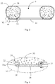
Fig. 1 is a schematic view of an ear muff according to a first embodiment of the present disclosure. -
Fig. 2 is a sectional view of the ear muff inFig. 1 . -
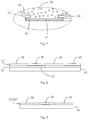
Fig. 3 is an enlarged view of part III circled by a dashed line inFig. 2 . -
Fig. 4 is a schematic view of an alternative embodiment similar toFig. 2 . -
Fig. 5 is a sectional view of an ear muff according to a second embodiment of the present disclosure. -
Fig. 6 is an enlarged view of part VI circled by a dashed line inFig. 5 . -
Fig. 7 is a schematic view of an alternative embodiment similar toFig. 6 . -
Fig. 8 is a partial side view of an ear muff according to a third embodiment of the present disclosure, and a direction of the side view refers to cutting plane line X-X inFig. 3 . -
Fig. 9 is a schematic view of an alternative embodiment similar toFig. 8 , and a direction of the sectional view refers to cutting plane line Y-Y inFig. 6 . - In order to make the objectives, technical solutions and advantages of the present disclosure more definite and clear, the present disclosure is further illustrated in detail in combination with a plurality of embodiments and accompanying drawings. It should be understood that, the specific embodiments described herein are only used for explaining the present disclosure and not for limiting the present disclosure. In addition, what illustrated in the accompanying drawings does not represent actual scale relations of various elements and is only used for illustration.
- In combination with
Figs. 1 to 3 , a first embodiment of the present disclosure provides anear muff 7. Theear muff 7 includes agasket 10, acovering piece 20 and asoft cushion 30. Thegasket 10 includes amounting surface 12, and themounting surface 12 has twoopposite side edges side edge 14 adjacent to a center of thegasket 10 and an outer-side edge 16 away from the center of thegasket 10. Thegasket 10 further includes a plurality ofrecesses 18 provided at the outer-side edge 16, that is, therecesses 18 extend to an outer-side surface of thegasket 10. Each of therecesses 18 includes aninner surface 18a. In the present embodiment, therecess 18 is a groove not penetrating a lower surface of thegasket 10. The lower surface is opposite to themounting surface 12. Thecovering piece 20 is fixed to the outer-side edge 16 providing therecesses 18 and does not contact with theinner surfaces 18a of therecesses 18. Specifically, in the present embodiment, the coveringpiece 20 is made of protein leather, man-made leather or the like, and includes twodistal ends side edge 16 in a manner such as hot-pressing or sewing. The two distal ends 22 and 24 do not contact theinner surfaces 18a of therecesses 18. Thus, a part of thecovering piece 20 fixed to the side edge forms a mounting portion, and a part thereof corresponding to therecess 18 forms a spacing portion. Thesoft cushion 30 may be made of sponge and covered in thecovering piece 20. - In the above-mentioned structure according to the first embodiment of the present disclosure, as the
covering piece 20 does not contact theinner surfaces 18a of therecesses 18 when fixes to the outer-side edge 16 of thegasket 10, portions of thedistal ends covering piece 20 corresponding to positions of therecesses 18 are not fixed to thegasket 10, in which case air can get in and out of thecovering piece 20 through the portions of thedistal ends soft cushion 30, so as to facilitate the deformation of thesoft cushion 30. With the above-mentioned structure provided in the present embodiment, it is not required to perforate thecovering piece 20, thereby reducing a rejection rate of the coveringpiece 20. - It could be understood that, the
recess 18 may also be a notch provided at the outer-side edge 16 and penetrating the lower surface of thegasket 10 in other embodiments, as illustrated inFig. 4 , in which case the above purpose of facilitating the deformation of thesoft cushion 10 can also be achieved. In addition, it could be understood that therecesses 18 may also be provided at the inner-side edge 14 in other embodiments, and thecovering piece 20 is fixed to the inner-side edge 14 and does not contact theinner surfaces 18a of therecesses 18 as well. - In combination with
Figs. 5 to 6 , which are schematic views of an ear muff 8 according to a second embodiment of the present disclosure, the ear muff 8 differs from theear muff 7 according to the first embodiment in that the inner-side edge 14 and the outer-side edge 16 of the mounting surface of thegasket 10 both provide with therecesses 18, and thedistal ends covering piece 20 are fixed to the inner-side edge 14 and the outer-side edge 16 respectively, in which similarly, the distal ends 22 and 24 do not contact theinner surfaces 18a of therecesses 18 as well. In the second embodiment, the ear muff 8 may be provided withmore recesses 18 than theear muff 7 in the first embodiment, such that it is more beneficial for the deformation of thesoft cushion 30. In addition, thedistal ends recesses 18, instead of overlapping each other in positions corresponding to therecesses 18, thus further facilitating the deformation of thesoft cushion 30. - Similarly, the
recess 18 may not only be the groove not penetrating the lower surface of thegasket 10 at the outer-side edge 16 illustrated inFig. 5 and Fig. 6 , but also be the notch penetrating the lower surface of thegasket 10 at the outer-side edge 16 thereof. In addition, therecess 18 is preferably configured as the groove not penetrating the lower surface of thegasket 10 and the groove extends from the outer-side edge 16 to the inner-side edge 14. In this structure, a part of therecess 18 located at a middle area inFig. 7 more adjoins thesoft cushion 30, thus facilitating the flow of more air. - In combination with
Figs. 8 and3 , which are side views of an ear muff according to a third embodiment of the present disclosure, the ear muff differs from theear muff 7 according to the first embodiment in that thegasket 10 is not provided with theabove recesses 18. In order to realize the same purpose as above, in the production process, the two distal ends 22 and 24 of the coveringpiece 20 are fixed to thegasket 10 discontinuously, instead of being fixed to thegasket 10 entirely. Specifically, the coveringpiece 20 includes a plurality of mountingportions 26 and a plurality ofspacing portions 28. Eachmounting portion 26 is arranged alternately with thespacing portion 28. The plurality of mountingportions 26 is fixed to anyside edge 16 or 14 (as illustrated inFig. 2 ), and the plurality ofspacing portions 28 is separable from the side edge. Thus, the air can get in and out of the covering piece through thespacing portions 28 separable from thegasket 10. It should be pointed out that a dashed line between themounting portion 26 and thespacing portion 28 adjacent to each other inFig. 8 are only intended for illustration. - In the embodiment illustrated in
Fig. 8 , the coveringpiece 10 includes twodistal ends portions 26 and the plurality ofspacing portions 28 are located at the two overlappeddistal ends portions 26 are fixed to the outer-side edge away from the center of thegasket 10. However, in combination withFigs. 6 and9 , it could be understood that the coveringpiece 10 may include twodistal ends distal ends portions 26 and the plurality ofspacing portions 28, and the mountingportions 26 of the respective distal ends are fixed to the outer-side edge 16 and the inner-side edge 14 respectively (as illustrated inFig. 5 ). - In the specification, terms such as "first" and "second" are used herein for purposes of description and are not intended to indicate or imply relative importance or significance or to imply the number of indicated technical features. Thus, the feature defined with "first" and "second" may comprise one or more of this feature. In the description of the present invention, "a plurality of'' means two or more than two, unless specified otherwise.
- In the present specification, unless specified or limited otherwise, the terms "mounted," "connected," "couple" and the like are used broadly, and may be, for example, fixed connections, detachable connections, or integral connections; may also be direct connections or indirect connections via intervening structures; may also be inner communications or interaction relationship of two elements, which can be understood by those skilled in the art according to specific situations.
- The descriptions above are only preferable embodiments of the present disclosure and are not used to limit the present disclosure. Any modifications, equal alternatives, and improvements made within the spirit and principle of the present disclosure should be included in the protection scope of the present disclosure.
Claims (10)
- An ear muff, comprising:a gasket comprising a mounting surface with two side edges opposite to each other;a covering piece comprising a plurality of mounting portions and a plurality of spacing portions, each mounting portion and each spacing portion being arranged alternatively, the plurality of mounting portions being fixed to any of the two side edges and the plurality of spacing portions being separable from the any of the two side edges; anda soft cushion covered in the covering piece.
- The ear muff according to claim 1, wherein the gasket further comprises a plurality of recesses arranged at at least one of the two side edges, each recess comprises an inner surface;
the covering piece is fixed to the side edge providing the recesses and does not contact with the inner surfaces of the recesses, a part fixed to the side edge is configured as the mounting portion, and a part corresponding to the recess is configured as the spacing portion. - The ear muff according to claim 2, wherein the recesses are provided in an outer-side edge away from a center of the gasket;
the covering piece comprises two opposite distal ends, and the two distal ends are both fixed to the outer-side edge. - The ear muff according to claim 3, wherein the recess is configured as a groove not penetrating the gasket or a notch penetrating the gasket.
- The ear muff according to claim 2, wherein the recesses are provided at both an outer-side edge away from a center of the gasket and an inner-side edge adjacent to the center of the gasket;
the covering piece comprises two opposite distal ends, and the two distal ends are fixed to the inner-side edge and the outer-side edge respectively. - The ear muff according to claim 5, wherein the inner-side edge and the outer-side edge are both provided with the recesses.
- The ear muff according to claim 6, wherein the recess is configured as a groove not penetrating the gasket or a notch penetrating the gasket.
- The ear muff according to claim 5, wherein the recess is configured as a groove not penetrating the gasket and extending from the outer-side edge to the inner-side edge.
- The ear muff according to claim 1, wherein the covering piece comprises two distal ends opposite to and overlapping each other, the plurality of mounting portions and the plurality of spacing portions are located at the two overlapped distal ends, and the mounting portions are fixed to an outer-side edge away from a center of the gasket.
- The ear muff according to claim 9, wherein the two opposite side edges comprise the outer-side edge away from the center of the gasket and an inner-side edge adjacent to the center of the gasket;
the covering piece comprises two distal ends opposite to each other, each of the two distal ends is provided with the plurality of mounting portions and the plurality of spacing portions, and the mounting portions of the two distal ends are fixed to the outer-side edge and the inner-side edge respectively.
Applications Claiming Priority (1)
| Application Number | Priority Date | Filing Date | Title |
|---|---|---|---|
| PCT/CN2015/083422 WO2017004784A1 (en) | 2015-07-07 | 2015-07-07 | Ear muff |
Publications (3)
| Publication Number | Publication Date |
|---|---|
| EP3276979A1 true EP3276979A1 (en) | 2018-01-31 |
| EP3276979A4 EP3276979A4 (en) | 2018-12-05 |
| EP3276979B1 EP3276979B1 (en) | 2020-06-03 |
Family
ID=56190120
Family Applications (1)
| Application Number | Title | Priority Date | Filing Date |
|---|---|---|---|
| EP15897440.2A Active EP3276979B1 (en) | 2015-07-07 | 2015-07-07 | Ear muff |
Country Status (6)
| Country | Link |
|---|---|
| US (1) | US20180139525A1 (en) |
| EP (1) | EP3276979B1 (en) |
| JP (1) | JP6549258B2 (en) |
| KR (1) | KR101930668B1 (en) |
| CN (1) | CN105684461B (en) |
| WO (1) | WO2017004784A1 (en) |
Families Citing this family (1)
| Publication number | Priority date | Publication date | Assignee | Title |
|---|---|---|---|---|
| CN112954533B (en) * | 2021-03-09 | 2023-04-25 | 歌尔科技有限公司 | Earmuff and headset |
Family Cites Families (24)
| Publication number | Priority date | Publication date | Assignee | Title |
|---|---|---|---|---|
| JPS50116Y1 (en) * | 1970-12-22 | 1975-01-06 | ||
| FI46023C (en) * | 1971-09-27 | 1972-12-11 | Exel Oy | How to attach the hearing protector gasket. |
| AT377664B (en) * | 1983-05-26 | 1985-04-25 | Akg Akustische Kino Geraete | EAR CUSHION |
| SE8604244L (en) * | 1986-10-06 | 1988-04-11 | Finnveden Holding Ab | HEAT PROTECTION PRESSURE RING |
| JP3254834B2 (en) * | 1993-08-06 | 2002-02-12 | 松下電器産業株式会社 | earphone |
| SE505203C2 (en) * | 1995-02-01 | 1997-07-14 | Bilsom Ab | A method for changing the sound attenuation of an earmuff as well as the earmuff according to the method |
| US5920911A (en) * | 1997-11-17 | 1999-07-13 | Poiesis Research, Inc. | Earcup soft-seal with thinned lips and interleaving layers of damping materials |
| GB9805619D0 (en) * | 1998-03-18 | 1998-05-13 | Noise Cancellation Tech | Cushioned earphones |
| SE514555C2 (en) * | 1999-07-08 | 2001-03-12 | Peltor Ab | Method of making cover and cover made according to the procedure |
| SE0100292D0 (en) * | 2001-02-01 | 2001-02-01 | Kompositprodukter Ab | Cover and washer for hearing protection |
| US6353938B1 (en) * | 2001-05-10 | 2002-03-12 | Moldex-Metric, Inc. | Sound attenuating earmuff |
| SE0600145L (en) * | 2006-01-24 | 2006-11-14 | Msa Sordin Ab | The ear cup |
| EP2127469A2 (en) * | 2006-12-04 | 2009-12-02 | Adaptive Technologies, Inc. | Sound-attenuating earmuff having isolated double-shell structure |
| CN201160318Y (en) * | 2007-09-24 | 2008-12-03 | 东莞市品泰海棉有限公司 | earmuffs |
| JP5082764B2 (en) * | 2007-10-25 | 2012-11-28 | ソニー株式会社 | Earpad and headphone device |
| US7717226B2 (en) * | 2008-02-20 | 2010-05-18 | Kimberly-Clark Worldwide, Inc. | Hearing protection cap |
| TW200939853A (en) * | 2008-03-14 | 2009-09-16 | Cotron Corp | Speaker structure capable of adjusting ventilation of a chamber therein |
| JP4333885B1 (en) * | 2008-09-26 | 2009-09-16 | フォスター電機株式会社 | earphone |
| US8374373B2 (en) * | 2008-11-26 | 2013-02-12 | Bose Corporation | High transmission loss headphone cushion |
| JP5297957B2 (en) * | 2009-09-16 | 2013-09-25 | 株式会社オーディオテクニカ | headphone |
| CN102487469B (en) * | 2010-12-03 | 2014-07-09 | 深圳市冠旭电子有限公司 | Ear shield and head-mounted noise reduction earphone |
| CN202979247U (en) * | 2012-12-10 | 2013-06-05 | 昆盈企业股份有限公司 | earphone |
| CN104105034B (en) * | 2013-04-03 | 2017-04-12 | 宝德科技股份有限公司 | Earphone device and control method thereof |
| CN203933906U (en) * | 2014-05-30 | 2014-11-05 | 深圳宝嘉能源有限公司 | A kind of headphone |
-
2015
- 2015-07-07 EP EP15897440.2A patent/EP3276979B1/en active Active
- 2015-07-07 US US15/572,689 patent/US20180139525A1/en not_active Abandoned
- 2015-07-07 KR KR1020177031198A patent/KR101930668B1/en not_active Expired - Fee Related
- 2015-07-07 WO PCT/CN2015/083422 patent/WO2017004784A1/en not_active Ceased
- 2015-07-07 CN CN201580002177.8A patent/CN105684461B/en not_active Expired - Fee Related
- 2015-07-07 JP JP2017565850A patent/JP6549258B2/en not_active Expired - Fee Related
Also Published As
| Publication number | Publication date |
|---|---|
| KR101930668B1 (en) | 2018-12-18 |
| EP3276979B1 (en) | 2020-06-03 |
| US20180139525A1 (en) | 2018-05-17 |
| EP3276979A4 (en) | 2018-12-05 |
| JP2018518125A (en) | 2018-07-05 |
| KR20170131847A (en) | 2017-11-30 |
| WO2017004784A1 (en) | 2017-01-12 |
| JP6549258B2 (en) | 2019-07-24 |
| CN105684461A (en) | 2016-06-15 |
| CN105684461B (en) | 2019-09-20 |
Similar Documents
| Publication | Publication Date | Title |
|---|---|---|
| USD842267S1 (en) | Headset | |
| US20130111648A1 (en) | Cushion for headband | |
| USD804445S1 (en) | In-ear headphones | |
| USD589235S1 (en) | Visor | |
| USD927671S1 (en) | Air purifier | |
| USD814440S1 (en) | Wireless audio headphones with magnetic ear cushions | |
| US20140112512A1 (en) | Sound channel formed in a case to redirect sound with respect to a speaker of an electronic device positioned in the case | |
| CN106455742A (en) | Communication system and device | |
| USD988295S1 (en) | Outer covering for earbud case | |
| US20180249779A1 (en) | Helmet Systems And Method For Operating The Same | |
| USD891734S1 (en) | Backless hat | |
| CN102625204A (en) | ear pads | |
| US20090014014A1 (en) | Ear Cup | |
| US20180139525A1 (en) | Ear muff | |
| TW201532651A (en) | Helmet padding system | |
| USD896359S1 (en) | Outdoor units for air conditioners | |
| JP3102559U (en) | Nose mask | |
| US20130329933A1 (en) | Hexagonal Headphone Earpiece | |
| CN205081929U (en) | Headphones and their on-ear eartips | |
| JP7386718B2 (en) | sound output device | |
| US2423355A (en) | Earphone socket structure | |
| KR101829260B1 (en) | Brassiere | |
| US20150163584A1 (en) | Audio device for headphone | |
| JP3228110U (en) | Face shield | |
| WO2019041365A1 (en) | Semi in-ear tip, earphone and manufacturing method thereof |
Legal Events
| Date | Code | Title | Description |
|---|---|---|---|
| STAA | Information on the status of an ep patent application or granted ep patent |
Free format text: STATUS: THE INTERNATIONAL PUBLICATION HAS BEEN MADE |
|
| PUAI | Public reference made under article 153(3) epc to a published international application that has entered the european phase |
Free format text: ORIGINAL CODE: 0009012 |
|
| STAA | Information on the status of an ep patent application or granted ep patent |
Free format text: STATUS: REQUEST FOR EXAMINATION WAS MADE |
|
| 17P | Request for examination filed |
Effective date: 20171027 |
|
| AK | Designated contracting states |
Kind code of ref document: A1 Designated state(s): AL AT BE BG CH CY CZ DE DK EE ES FI FR GB GR HR HU IE IS IT LI LT LU LV MC MK MT NL NO PL PT RO RS SE SI SK SM TR |
|
| AX | Request for extension of the european patent |
Extension state: BA ME |
|
| DAV | Request for validation of the european patent (deleted) | ||
| DAX | Request for extension of the european patent (deleted) | ||
| A4 | Supplementary search report drawn up and despatched |
Effective date: 20181026 |
|
| RIC1 | Information provided on ipc code assigned before grant |
Ipc: H04R 1/10 20060101AFI20181022BHEP |
|
| GRAP | Despatch of communication of intention to grant a patent |
Free format text: ORIGINAL CODE: EPIDOSNIGR1 |
|
| STAA | Information on the status of an ep patent application or granted ep patent |
Free format text: STATUS: GRANT OF PATENT IS INTENDED |
|
| INTG | Intention to grant announced |
Effective date: 20200107 |
|
| GRAS | Grant fee paid |
Free format text: ORIGINAL CODE: EPIDOSNIGR3 |
|
| GRAA | (expected) grant |
Free format text: ORIGINAL CODE: 0009210 |
|
| STAA | Information on the status of an ep patent application or granted ep patent |
Free format text: STATUS: THE PATENT HAS BEEN GRANTED |
|
| AK | Designated contracting states |
Kind code of ref document: B1 Designated state(s): AL AT BE BG CH CY CZ DE DK EE ES FI FR GB GR HR HU IE IS IT LI LT LU LV MC MK MT NL NO PL PT RO RS SE SI SK SM TR |
|
| REG | Reference to a national code |
Ref country code: GB Ref legal event code: FG4D |
|
| REG | Reference to a national code |
Ref country code: CH Ref legal event code: EP Ref country code: AT Ref legal event code: REF Ref document number: 1278321 Country of ref document: AT Kind code of ref document: T Effective date: 20200615 |
|
| REG | Reference to a national code |
Ref country code: DE Ref legal event code: R096 Ref document number: 602015053953 Country of ref document: DE |
|
| PGFP | Annual fee paid to national office [announced via postgrant information from national office to epo] |
Ref country code: GB Payment date: 20200605 Year of fee payment: 6 |
|
| REG | Reference to a national code |
Ref country code: LT Ref legal event code: MG4D |
|
| PG25 | Lapsed in a contracting state [announced via postgrant information from national office to epo] |
Ref country code: LT Free format text: LAPSE BECAUSE OF FAILURE TO SUBMIT A TRANSLATION OF THE DESCRIPTION OR TO PAY THE FEE WITHIN THE PRESCRIBED TIME-LIMIT Effective date: 20200603 Ref country code: FI Free format text: LAPSE BECAUSE OF FAILURE TO SUBMIT A TRANSLATION OF THE DESCRIPTION OR TO PAY THE FEE WITHIN THE PRESCRIBED TIME-LIMIT Effective date: 20200603 Ref country code: GR Free format text: LAPSE BECAUSE OF FAILURE TO SUBMIT A TRANSLATION OF THE DESCRIPTION OR TO PAY THE FEE WITHIN THE PRESCRIBED TIME-LIMIT Effective date: 20200904 Ref country code: SE Free format text: LAPSE BECAUSE OF FAILURE TO SUBMIT A TRANSLATION OF THE DESCRIPTION OR TO PAY THE FEE WITHIN THE PRESCRIBED TIME-LIMIT Effective date: 20200603 Ref country code: NO Free format text: LAPSE BECAUSE OF FAILURE TO SUBMIT A TRANSLATION OF THE DESCRIPTION OR TO PAY THE FEE WITHIN THE PRESCRIBED TIME-LIMIT Effective date: 20200903 |
|
| REG | Reference to a national code |
Ref country code: NL Ref legal event code: MP Effective date: 20200603 |
|
| PG25 | Lapsed in a contracting state [announced via postgrant information from national office to epo] |
Ref country code: HR Free format text: LAPSE BECAUSE OF FAILURE TO SUBMIT A TRANSLATION OF THE DESCRIPTION OR TO PAY THE FEE WITHIN THE PRESCRIBED TIME-LIMIT Effective date: 20200603 Ref country code: RS Free format text: LAPSE BECAUSE OF FAILURE TO SUBMIT A TRANSLATION OF THE DESCRIPTION OR TO PAY THE FEE WITHIN THE PRESCRIBED TIME-LIMIT Effective date: 20200603 Ref country code: BG Free format text: LAPSE BECAUSE OF FAILURE TO SUBMIT A TRANSLATION OF THE DESCRIPTION OR TO PAY THE FEE WITHIN THE PRESCRIBED TIME-LIMIT Effective date: 20200903 Ref country code: LV Free format text: LAPSE BECAUSE OF FAILURE TO SUBMIT A TRANSLATION OF THE DESCRIPTION OR TO PAY THE FEE WITHIN THE PRESCRIBED TIME-LIMIT Effective date: 20200603 |
|
| REG | Reference to a national code |
Ref country code: AT Ref legal event code: MK05 Ref document number: 1278321 Country of ref document: AT Kind code of ref document: T Effective date: 20200603 |
|
| PG25 | Lapsed in a contracting state [announced via postgrant information from national office to epo] |
Ref country code: AL Free format text: LAPSE BECAUSE OF FAILURE TO SUBMIT A TRANSLATION OF THE DESCRIPTION OR TO PAY THE FEE WITHIN THE PRESCRIBED TIME-LIMIT Effective date: 20200603 Ref country code: NL Free format text: LAPSE BECAUSE OF FAILURE TO SUBMIT A TRANSLATION OF THE DESCRIPTION OR TO PAY THE FEE WITHIN THE PRESCRIBED TIME-LIMIT Effective date: 20200603 |
|
| PG25 | Lapsed in a contracting state [announced via postgrant information from national office to epo] |
Ref country code: IT Free format text: LAPSE BECAUSE OF FAILURE TO SUBMIT A TRANSLATION OF THE DESCRIPTION OR TO PAY THE FEE WITHIN THE PRESCRIBED TIME-LIMIT Effective date: 20200603 Ref country code: ES Free format text: LAPSE BECAUSE OF FAILURE TO SUBMIT A TRANSLATION OF THE DESCRIPTION OR TO PAY THE FEE WITHIN THE PRESCRIBED TIME-LIMIT Effective date: 20200603 Ref country code: CZ Free format text: LAPSE BECAUSE OF FAILURE TO SUBMIT A TRANSLATION OF THE DESCRIPTION OR TO PAY THE FEE WITHIN THE PRESCRIBED TIME-LIMIT Effective date: 20200603 Ref country code: RO Free format text: LAPSE BECAUSE OF FAILURE TO SUBMIT A TRANSLATION OF THE DESCRIPTION OR TO PAY THE FEE WITHIN THE PRESCRIBED TIME-LIMIT Effective date: 20200603 Ref country code: EE Free format text: LAPSE BECAUSE OF FAILURE TO SUBMIT A TRANSLATION OF THE DESCRIPTION OR TO PAY THE FEE WITHIN THE PRESCRIBED TIME-LIMIT Effective date: 20200603 Ref country code: AT Free format text: LAPSE BECAUSE OF FAILURE TO SUBMIT A TRANSLATION OF THE DESCRIPTION OR TO PAY THE FEE WITHIN THE PRESCRIBED TIME-LIMIT Effective date: 20200603 Ref country code: SM Free format text: LAPSE BECAUSE OF FAILURE TO SUBMIT A TRANSLATION OF THE DESCRIPTION OR TO PAY THE FEE WITHIN THE PRESCRIBED TIME-LIMIT Effective date: 20200603 Ref country code: PT Free format text: LAPSE BECAUSE OF FAILURE TO SUBMIT A TRANSLATION OF THE DESCRIPTION OR TO PAY THE FEE WITHIN THE PRESCRIBED TIME-LIMIT Effective date: 20201006 |
|
| REG | Reference to a national code |
Ref country code: DE Ref legal event code: R119 Ref document number: 602015053953 Country of ref document: DE |
|
| PG25 | Lapsed in a contracting state [announced via postgrant information from national office to epo] |
Ref country code: SK Free format text: LAPSE BECAUSE OF FAILURE TO SUBMIT A TRANSLATION OF THE DESCRIPTION OR TO PAY THE FEE WITHIN THE PRESCRIBED TIME-LIMIT Effective date: 20200603 Ref country code: PL Free format text: LAPSE BECAUSE OF FAILURE TO SUBMIT A TRANSLATION OF THE DESCRIPTION OR TO PAY THE FEE WITHIN THE PRESCRIBED TIME-LIMIT Effective date: 20200603 Ref country code: IS Free format text: LAPSE BECAUSE OF FAILURE TO SUBMIT A TRANSLATION OF THE DESCRIPTION OR TO PAY THE FEE WITHIN THE PRESCRIBED TIME-LIMIT Effective date: 20201003 |
|
| REG | Reference to a national code |
Ref country code: CH Ref legal event code: PL |
|
| PG25 | Lapsed in a contracting state [announced via postgrant information from national office to epo] |
Ref country code: MC Free format text: LAPSE BECAUSE OF FAILURE TO SUBMIT A TRANSLATION OF THE DESCRIPTION OR TO PAY THE FEE WITHIN THE PRESCRIBED TIME-LIMIT Effective date: 20200603 |
|
| PLBE | No opposition filed within time limit |
Free format text: ORIGINAL CODE: 0009261 |
|
| STAA | Information on the status of an ep patent application or granted ep patent |
Free format text: STATUS: NO OPPOSITION FILED WITHIN TIME LIMIT |
|
| REG | Reference to a national code |
Ref country code: BE Ref legal event code: MM Effective date: 20200731 |
|
| PG25 | Lapsed in a contracting state [announced via postgrant information from national office to epo] |
Ref country code: LU Free format text: LAPSE BECAUSE OF NON-PAYMENT OF DUE FEES Effective date: 20200707 Ref country code: LI Free format text: LAPSE BECAUSE OF NON-PAYMENT OF DUE FEES Effective date: 20200731 Ref country code: FR Free format text: LAPSE BECAUSE OF NON-PAYMENT OF DUE FEES Effective date: 20200803 Ref country code: IE Free format text: LAPSE BECAUSE OF NON-PAYMENT OF DUE FEES Effective date: 20200707 Ref country code: DK Free format text: LAPSE BECAUSE OF FAILURE TO SUBMIT A TRANSLATION OF THE DESCRIPTION OR TO PAY THE FEE WITHIN THE PRESCRIBED TIME-LIMIT Effective date: 20200603 Ref country code: CH Free format text: LAPSE BECAUSE OF NON-PAYMENT OF DUE FEES Effective date: 20200731 |
|
| 26N | No opposition filed |
Effective date: 20210304 |
|
| PG25 | Lapsed in a contracting state [announced via postgrant information from national office to epo] |
Ref country code: BE Free format text: LAPSE BECAUSE OF NON-PAYMENT OF DUE FEES Effective date: 20200731 Ref country code: DE Free format text: LAPSE BECAUSE OF NON-PAYMENT OF DUE FEES Effective date: 20210202 Ref country code: SI Free format text: LAPSE BECAUSE OF FAILURE TO SUBMIT A TRANSLATION OF THE DESCRIPTION OR TO PAY THE FEE WITHIN THE PRESCRIBED TIME-LIMIT Effective date: 20200603 |
|
| GBPC | Gb: european patent ceased through non-payment of renewal fee |
Effective date: 20210707 |
|
| PG25 | Lapsed in a contracting state [announced via postgrant information from national office to epo] |
Ref country code: GB Free format text: LAPSE BECAUSE OF NON-PAYMENT OF DUE FEES Effective date: 20210707 |
|
| PG25 | Lapsed in a contracting state [announced via postgrant information from national office to epo] |
Ref country code: TR Free format text: LAPSE BECAUSE OF FAILURE TO SUBMIT A TRANSLATION OF THE DESCRIPTION OR TO PAY THE FEE WITHIN THE PRESCRIBED TIME-LIMIT Effective date: 20200603 Ref country code: MT Free format text: LAPSE BECAUSE OF FAILURE TO SUBMIT A TRANSLATION OF THE DESCRIPTION OR TO PAY THE FEE WITHIN THE PRESCRIBED TIME-LIMIT Effective date: 20200603 Ref country code: CY Free format text: LAPSE BECAUSE OF FAILURE TO SUBMIT A TRANSLATION OF THE DESCRIPTION OR TO PAY THE FEE WITHIN THE PRESCRIBED TIME-LIMIT Effective date: 20200603 |
|
| PG25 | Lapsed in a contracting state [announced via postgrant information from national office to epo] |
Ref country code: MK Free format text: LAPSE BECAUSE OF FAILURE TO SUBMIT A TRANSLATION OF THE DESCRIPTION OR TO PAY THE FEE WITHIN THE PRESCRIBED TIME-LIMIT Effective date: 20200603 |