EP3276753A1 - Computer with cable access door - Google Patents
Computer with cable access door Download PDFInfo
- Publication number
- EP3276753A1 EP3276753A1 EP17183090.4A EP17183090A EP3276753A1 EP 3276753 A1 EP3276753 A1 EP 3276753A1 EP 17183090 A EP17183090 A EP 17183090A EP 3276753 A1 EP3276753 A1 EP 3276753A1
- Authority
- EP
- European Patent Office
- Prior art keywords
- access door
- cable access
- computer
- housing
- cable
- Prior art date
- Legal status (The legal status is an assumption and is not a legal conclusion. Google has not performed a legal analysis and makes no representation as to the accuracy of the status listed.)
- Granted
Links
Images



Classifications
-
- H—ELECTRICITY
- H01—ELECTRIC ELEMENTS
- H01R—ELECTRICALLY-CONDUCTIVE CONNECTIONS; STRUCTURAL ASSOCIATIONS OF A PLURALITY OF MUTUALLY-INSULATED ELECTRICAL CONNECTING ELEMENTS; COUPLING DEVICES; CURRENT COLLECTORS
- H01R13/00—Details of coupling devices of the kinds covered by groups H01R12/70 or H01R24/00 - H01R33/00
- H01R13/62—Means for facilitating engagement or disengagement of coupling parts or for holding them in engagement
- H01R13/629—Additional means for facilitating engagement or disengagement of coupling parts, e.g. aligning or guiding means, levers, gas pressure electrical locking indicators, manufacturing tolerances
-
- G—PHYSICS
- G06—COMPUTING OR CALCULATING; COUNTING
- G06F—ELECTRIC DIGITAL DATA PROCESSING
- G06F1/00—Details not covered by groups G06F3/00 - G06F13/00 and G06F21/00
- G06F1/16—Constructional details or arrangements
- G06F1/18—Packaging or power distribution
- G06F1/181—Enclosures
- G06F1/182—Enclosures with special features, e.g. for use in industrial environments; grounding or shielding against radio frequency interference [RFI] or electromagnetical interference [EMI]
-
- A—HUMAN NECESSITIES
- A47—FURNITURE; DOMESTIC ARTICLES OR APPLIANCES; COFFEE MILLS; SPICE MILLS; SUCTION CLEANERS IN GENERAL
- A47B—TABLES; DESKS; OFFICE FURNITURE; CABINETS; DRAWERS; GENERAL DETAILS OF FURNITURE
- A47B21/00—Tables or desks for office equipment, e.g. typewriters, keyboards
- A47B21/06—Tables or desks for office equipment, e.g. typewriters, keyboards characterised by means for holding, fastening or concealing cables
-
- G—PHYSICS
- G06—COMPUTING OR CALCULATING; COUNTING
- G06F—ELECTRIC DIGITAL DATA PROCESSING
- G06F1/00—Details not covered by groups G06F3/00 - G06F13/00 and G06F21/00
- G06F1/16—Constructional details or arrangements
- G06F1/1613—Constructional details or arrangements for portable computers
- G06F1/1633—Constructional details or arrangements of portable computers not specific to the type of enclosures covered by groups G06F1/1615 - G06F1/1626
- G06F1/1656—Details related to functional adaptations of the enclosure, e.g. to provide protection against EMI, shock, water, or to host detachable peripherals like a mouse or removable expansions units like PCMCIA cards, or to provide access to internal components for maintenance or to removable storage supports like CDs or DVDs, or to mechanically mount accessories
-
- G—PHYSICS
- G06—COMPUTING OR CALCULATING; COUNTING
- G06F—ELECTRIC DIGITAL DATA PROCESSING
- G06F1/00—Details not covered by groups G06F3/00 - G06F13/00 and G06F21/00
- G06F1/16—Constructional details or arrangements
- G06F1/18—Packaging or power distribution
- G06F1/181—Enclosures
-
- H—ELECTRICITY
- H01—ELECTRIC ELEMENTS
- H01R—ELECTRICALLY-CONDUCTIVE CONNECTIONS; STRUCTURAL ASSOCIATIONS OF A PLURALITY OF MUTUALLY-INSULATED ELECTRICAL CONNECTING ELEMENTS; COUPLING DEVICES; CURRENT COLLECTORS
- H01R13/00—Details of coupling devices of the kinds covered by groups H01R12/70 or H01R24/00 - H01R33/00
- H01R13/46—Bases; Cases
- H01R13/502—Bases; Cases composed of different pieces
-
- H—ELECTRICITY
- H01—ELECTRIC ELEMENTS
- H01R—ELECTRICALLY-CONDUCTIVE CONNECTIONS; STRUCTURAL ASSOCIATIONS OF A PLURALITY OF MUTUALLY-INSULATED ELECTRICAL CONNECTING ELEMENTS; COUPLING DEVICES; CURRENT COLLECTORS
- H01R13/00—Details of coupling devices of the kinds covered by groups H01R12/70 or H01R24/00 - H01R33/00
- H01R13/62—Means for facilitating engagement or disengagement of coupling parts or for holding them in engagement
- H01R13/627—Snap or like fastening
-
- H—ELECTRICITY
- H01—ELECTRIC ELEMENTS
- H01R—ELECTRICALLY-CONDUCTIVE CONNECTIONS; STRUCTURAL ASSOCIATIONS OF A PLURALITY OF MUTUALLY-INSULATED ELECTRICAL CONNECTING ELEMENTS; COUPLING DEVICES; CURRENT COLLECTORS
- H01R13/00—Details of coupling devices of the kinds covered by groups H01R12/70 or H01R24/00 - H01R33/00
- H01R13/72—Means for accommodating flexible lead within the holder
-
- H—ELECTRICITY
- H01—ELECTRIC ELEMENTS
- H01R—ELECTRICALLY-CONDUCTIVE CONNECTIONS; STRUCTURAL ASSOCIATIONS OF A PLURALITY OF MUTUALLY-INSULATED ELECTRICAL CONNECTING ELEMENTS; COUPLING DEVICES; CURRENT COLLECTORS
- H01R2201/00—Connectors or connections adapted for particular applications
- H01R2201/06—Connectors or connections adapted for particular applications for computer periphery
Definitions
- Computer terminals used in retail point-of-sale (POS) and other environments typically have many ports and other connectors for power, monitor, keyboard, mouse, and a variety of peripherals, with many connected cables. Many consider cable connectors to be unsightly. Exposed cables are also subject to a risk of being disconnected
- a computer with cable access door is provided.
- the computer includes a housing including a cable access door having an open position and a closed position and a connector within the housing for connecting to a cable originating from outside the housing.
- the cable access door conceals the connector and the cable when the cable access door is in the closed position.
- the computer in another example embodiment, includes a housing including an upper portion and a lower portion.
- the upper portion includes a cable access door having an open position and a closed position.
- the lower portion includes an aperture opposite the cable access door.
- a connector panel in the housing extends between the cable access door and the aperture, and the connector panel includes a plurality of connectors for connecting to cables originating from outside the housing and passing through the aperture from underneath the housing.
- the cable access door conceals the connector and the cables when the cable access door is in the closed position.
- a computer comprising: a housing including a cable access door having an open position and a closed position; and a connector within the housing for connecting to a cable originating from outside the housing; wherein the cable access door conceals the connector and the cable when the cable access door is in the closed position.
- the computer may further comprise a connector panel containing the one connector and a plurality of additional connectors.
- the computer may further comprise a strengthening plate underlying the cable access door.
- the computer the strengthening plate may be attached to the cable access door using heat stake posts.
- the cable access door may comprise a snap which engages with a latch member in the housing to secure the cable access door in the closed position.
- the cable may apply a transverse force to the snap that strengthens a locking force between the snap and the latch member.
- the cable access door may further comprise a flexible opening portion which disengages the snap from the latch member when force is applied to the flexible opening portion.
- the cable access door may further comprise first and second pivoting arms at opposite ends of the cable access door.
- first and second pivoting arms may be each coupled to corresponding hinge.
- the housing may further comprise an edge support member that supports an edge of the cable access door.
- a computer comprising: a housing including an upper portion and a lower portion, wherein the upper portion includes a cable access door having an open position and a closed position, and wherein the lower portion includes an aperture opposite the cable access door; and a connector panel in the housing extending between the cable access door and the aperture, the connector panel including a plurality of connectors for connecting to cables originating from outside the housing and passing through the aperture from underneath the housing; wherein the cable access door conceals the connector and the cables when the cable access door is in the closed position.
- the cable access door may comprise a plurality of snaps which engage corresponding latch members in the housing to secure the cable access door in the closed position.
- each latch member may comprise a latch hook and each snap comprises a flexible snap hook which engages the latch hook.
- the cable access door further may comprise a flexible opening portion coupled to the snaps which disengages the snap hooks from the latch hooks when an opening force is applied to the flexible opening portion.
- the cables may apply a force to the snaps that is transverse to a locking force between the snap and the latch member and that opposes the opening force.
- an example computer 10 includes a housing 20.
- Housing 20 includes an upper housing portion 30, a lower housing portion 40, and cable access door 50.
- Cable access door 50 includes a first cover portion 60 adjacent upper housing portion 30.
- cable access door 50 may alternatively be viewed as being part of upper housing portion 30.
- Cable access door 50 further includes a second cover portion 70 extending between opposite side portions 80 of lower housing portion 40.
- Second cover portion 70 is flexible to facilitate opening of cable access door 50, and may additionally include tactile members 90 on each end, which aid an operator in opening cable access door 50.
- cable access door 50 has cable retention features which prevent cable access door 50 from unintentionally opening.
- One cable retention feature is plate 150.
- Plate 150 includes a first portion 160, which supports the top portion of cable access door 50.
- a second portion 170 supports the contoured surface of cable access door 50.
- a third portion 180 reinforces lower cover portion 70.
- plate 150 may also serve to strengthen cable access door 50 against breakage and maintain its shape following manufacture. In one example, plate 150 may be added during manufacturing to prevent warping of cable access door 50. Plate 150 may be attached with heat stake posts 195 through corresponding apertures in plate 150, which is a lower cost option than using screws and eliminates the need for corresponding mounting bosses that would decrease the available underlying space for cables.
- housing 20 includes edge support 200.
- Edge support 200 supports the long edge of cable access door 50 adjacent upper housing portion 30.
- First cover portion 60 includes snaps 120 on opposite sides of lower cover portion 70, close to tactile members 90. With reference to Fig. 4 , snaps 120 are aligned with, and engage, opposing latch members 130 of side portions 80. Each latch member 130 includes a latch hook 220 which engages a corresponding snap hook 210 on each of snaps 120. Opposing forces between snap hook 210 and latch hook 220 are substantially vertical. Thus, the outward orientation of snap hook 210 strengthens the locking force when a transverse pressure is applied against the inside of cable access door 50 by connected cables.
- an operator opens cable access door 50 by gently pressing on tactile members 90 to slightly bend lower cover portion 70 and snaps 120 inwards, thereby allowing snap hooks 210 disengage from latch hooks 220.
- Part of the force required to release snaps 120 may include opposing forces from cables on the opposite side of lower cover portion 70.
- a stop portion 230 of each latch member 130 limits bending of lower cover portion 70 and snaps 120 to prevent breakage. The operator continues to press tactile members 90 while rotating cable access door 50 upwards until snaps 120 have cleared latch members 130.
- Closing cable access door 50 involves rotating cable access door 50 downwards until snap hooks 210 engage latch hooks 220.
- cable access door 50 includes support arms 100 which extend from and recede into arm slots 110 during opening and closing.
- each support arm 100 includes an axle portion 260.
- Axle portion 260 rotates on lower hinge member 300.
- Upper hinge member 290 is generally U-shaped and retains axle portion 260 in position over lower hinge member 300.
- Upper hinge member 290 may also provide a friction fit against axle portion 260 to dampen rotation of cable access door 50.
- Lower housing portion 40 may include a depression 270 under each support arm 100 and each depression 270 may include an aperture 280. Together, depression 270 and aperture 280 provide sufficient clearance for support arm 100 to rotate to a closed position without striking the bottom surface of lower housing portion 40.
- Housing 20 contains one or more circuit boards with one or more processors, memory, and program and data storage.
- the one or more circuit boards also include ports and/or input/output connectors 145 which are organized within a connector panel 140.
- Example ports and/or connectors 145 accessible through the connector panel 140 include network ports, serial ports, video ports, audio ports, and power connectors.
- Lower housing portion 40 includes an aperture 190 to facilitate routing of cables from under lower housing portion 40 to connector panel 140.
- FIG. 6 an example configuration is illustrated in which computer 10 is oriented with cable access door 50 facing an operator.
- cable 330 is routed below lower housing portion 40 and away from the operator to the opposite side of computer 10.
- cable access door 50 may be oriented away from an operator and cable 330 routed below and away from the operator.
- cable access door 50 facilitates concealment of cable connectors and is secure from outward forces produced by cable 330. Cable 330 is hidden where it connects to connector 145 and where it runs beneath computer 10.
- computer 10 be used with various peripherals suited to its purpose.
- computer 10 may include a point-of-sale (POS) terminal and include cable connectors for a monitor, cash drawer, receipt printer, and barcode scanner, in addition to network and other cable connectors.
- POS point-of-sale
- cable connectors for a monitor, cash drawer, receipt printer, and barcode scanner, in addition to network and other cable connectors.
- Other configurations are also envisioned.
Landscapes
- Engineering & Computer Science (AREA)
- Theoretical Computer Science (AREA)
- Computer Hardware Design (AREA)
- Physics & Mathematics (AREA)
- General Engineering & Computer Science (AREA)
- Human Computer Interaction (AREA)
- General Physics & Mathematics (AREA)
- Power Engineering (AREA)
- Electromagnetism (AREA)
- Insertion, Bundling And Securing Of Wires For Electric Apparatuses (AREA)
- Casings For Electric Apparatus (AREA)
- Installation Of Indoor Wiring (AREA)
Abstract
Description
- Computer terminals used in retail point-of-sale (POS) and other environments typically have many ports and other connectors for power, monitor, keyboard, mouse, and a variety of peripherals, with many connected cables. Many consider cable connectors to be unsightly. Exposed cables are also subject to a risk of being disconnected
- Therefore, it would be desirable to provide a computer terminal with a cable access door that helps maintain cable connections and shield them from view.
- A computer with cable access door is provided.
- In one example embodiment, the computer includes a housing including a cable access door having an open position and a closed position and a connector within the housing for connecting to a cable originating from outside the housing. The cable access door conceals the connector and the cable when the cable access door is in the closed position.
- In another example embodiment, the computer includes a housing including an upper portion and a lower portion. The upper portion includes a cable access door having an open position and a closed position. The lower portion includes an aperture opposite the cable access door. A connector panel in the housing extends between the cable access door and the aperture, and the connector panel includes a plurality of connectors for connecting to cables originating from outside the housing and passing through the aperture from underneath the housing. The cable access door conceals the connector and the cables when the cable access door is in the closed position.
- According to a first aspect of the invention, there is provided a computer comprising: a housing including a cable access door having an open position and a closed position; and a connector within the housing for connecting to a cable originating from outside the housing; wherein the cable access door conceals the connector and the cable when the cable access door is in the closed position.
- Optionally, the computer may further comprise a connector panel containing the one connector and a plurality of additional connectors.
- Optionally, the computer may further comprise a strengthening plate underlying the cable access door.
- Optionally, the computer the strengthening plate may be attached to the cable access door using heat stake posts.
- Optionally, the cable access door may comprise a snap which engages with a latch member in the housing to secure the cable access door in the closed position.
- Optionally, the cable may apply a transverse force to the snap that strengthens a locking force between the snap and the latch member.
- Optionally, the cable access door may further comprise a flexible opening portion which disengages the snap from the latch member when force is applied to the flexible opening portion.
- Optionally, the cable access door may further comprise first and second pivoting arms at opposite ends of the cable access door.
- Optionally, the first and second pivoting arms may be each coupled to corresponding hinge.
- Optionally, the housing may further comprise an edge support member that supports an edge of the cable access door.
- According to a second aspect of the invention, there is provided a computer comprising: a housing including an upper portion and a lower portion, wherein the upper portion includes a cable access door having an open position and a closed position, and wherein the lower portion includes an aperture opposite the cable access door; and a connector panel in the housing extending between the cable access door and the aperture, the connector panel including a plurality of connectors for connecting to cables originating from outside the housing and passing through the aperture from underneath the housing; wherein the cable access door conceals the connector and the cables when the cable access door is in the closed position.
- Optionally, the cable access door may comprise a plurality of snaps which engage corresponding latch members in the housing to secure the cable access door in the closed position.
- Optionally, each latch member may comprise a latch hook and each snap comprises a flexible snap hook which engages the latch hook.
- Optionally, the cable access door further may comprise a flexible opening portion coupled to the snaps which disengages the snap hooks from the latch hooks when an opening force is applied to the flexible opening portion.
- Optionally, the cables may apply a force to the snaps that is transverse to a locking force between the snap and the latch member and that opposes the opening force.
- These and other aspects of the present invention will be apparent from the following specific description, given by way of example, with reference to the accompanying drawings, in which:
-
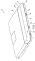
Fig. 1 is a perspective view of an example computer with a cable access door in a closed position. -
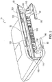
Fig. 2 is a perspective view of the example computer with the cable access door in a partially open position. -
Fig. 3 is a perspective view of the example computer with the cable access door in a fully open position. -
Fig. 4 is a cross-section of the example computer illustrating a latch feature of the cable access door. -
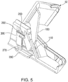
Fig. 5 is a partial view the example computer illustrating a hinge feature of the cable access door. -
Fig. 6 is a cross-section of the example computer with the cable access door in the closed position. - Referring now to
Figs. 1-3 , anexample computer 10 includes ahousing 20.Housing 20 includes anupper housing portion 30, alower housing portion 40, andcable access door 50. -
Cable access door 50 includes afirst cover portion 60 adjacentupper housing portion 30. In the example embodiment,cable access door 50 may alternatively be viewed as being part ofupper housing portion 30.Cable access door 50 further includes asecond cover portion 70 extending betweenopposite side portions 80 oflower housing portion 40.Second cover portion 70 is flexible to facilitate opening ofcable access door 50, and may additionally includetactile members 90 on each end, which aid an operator in openingcable access door 50. - With reference to
Figs. 2 and3 ,cable access door 50 has cable retention features which preventcable access door 50 from unintentionally opening. One cable retention feature isplate 150.Plate 150 includes afirst portion 160, which supports the top portion ofcable access door 50. Asecond portion 170 supports the contoured surface ofcable access door 50. Athird portion 180 reinforceslower cover portion 70. - Since
housing 20 may be made of plastic,plate 150 may also serve to strengthencable access door 50 against breakage and maintain its shape following manufacture. In one example,plate 150 may be added during manufacturing to prevent warping ofcable access door 50.Plate 150 may be attached withheat stake posts 195 through corresponding apertures inplate 150, which is a lower cost option than using screws and eliminates the need for corresponding mounting bosses that would decrease the available underlying space for cables. - To further protect
cable access door 50 from breakage,housing 20 includesedge support 200.Edge support 200 supports the long edge ofcable access door 50 adjacentupper housing portion 30. - Another cable retention feature is the cable door latching mechanism.
First cover portion 60 includessnaps 120 on opposite sides oflower cover portion 70, close totactile members 90. With reference toFig. 4 ,snaps 120 are aligned with, and engage, opposinglatch members 130 ofside portions 80. Eachlatch member 130 includes alatch hook 220 which engages acorresponding snap hook 210 on each ofsnaps 120. Opposing forces betweensnap hook 210 andlatch hook 220 are substantially vertical. Thus, the outward orientation ofsnap hook 210 strengthens the locking force when a transverse pressure is applied against the inside ofcable access door 50 by connected cables. - In the example embodiment, an operator opens
cable access door 50 by gently pressing ontactile members 90 to slightly bendlower cover portion 70 and snaps 120 inwards, thereby allowingsnap hooks 210 disengage fromlatch hooks 220. Part of the force required to releasesnaps 120 may include opposing forces from cables on the opposite side oflower cover portion 70. Astop portion 230 of eachlatch member 130 limits bending oflower cover portion 70 andsnaps 120 to prevent breakage. The operator continues to presstactile members 90 while rotatingcable access door 50 upwards untilsnaps 120 have clearedlatch members 130. - Closing
cable access door 50 involves rotatingcable access door 50 downwards untilsnap hooks 210 engagelatch hooks 220. - Returning to
Figs. 2 and3 ,cable access door 50 includessupport arms 100 which extend from and recede intoarm slots 110 during opening and closing. With reference toFig. 5 , eachsupport arm 100 includes anaxle portion 260.Axle portion 260 rotates onlower hinge member 300.Upper hinge member 290 is generally U-shaped and retainsaxle portion 260 in position overlower hinge member 300.Upper hinge member 290 may also provide a friction fit againstaxle portion 260 to dampen rotation ofcable access door 50.Lower housing portion 40 may include adepression 270 under eachsupport arm 100 and eachdepression 270 may include anaperture 280. Together,depression 270 andaperture 280 provide sufficient clearance forsupport arm 100 to rotate to a closed position without striking the bottom surface oflower housing portion 40. -
Housing 20 contains one or more circuit boards with one or more processors, memory, and program and data storage. The one or more circuit boards also include ports and/or input/output connectors 145 which are organized within aconnector panel 140. Example ports and/orconnectors 145 accessible through theconnector panel 140 include network ports, serial ports, video ports, audio ports, and power connectors.Lower housing portion 40 includes anaperture 190 to facilitate routing of cables from underlower housing portion 40 toconnector panel 140. - With reference to
Fig. 6 , an example configuration is illustrated in whichcomputer 10 is oriented withcable access door 50 facing an operator. In this configuration,cable 330 is routed belowlower housing portion 40 and away from the operator to the opposite side ofcomputer 10. - Other configurations are also envisioned. For example,
cable access door 50 may be oriented away from an operator andcable 330 routed below and away from the operator. - Advantageously,
cable access door 50 facilitates concealment of cable connectors and is secure from outward forces produced bycable 330.Cable 330 is hidden where it connects toconnector 145 and where it runs beneathcomputer 10. - It is envisioned that
computer 10 be used with various peripherals suited to its purpose. For example,computer 10 may include a point-of-sale (POS) terminal and include cable connectors for a monitor, cash drawer, receipt printer, and barcode scanner, in addition to network and other cable connectors. Other configurations are also envisioned. - In the foregoing description of the embodiments, various features are grouped together in a single embodiment for the purpose of streamlining the disclosure. This method of disclosure is not to be interpreted as reflecting that the claimed embodiments have more features than are expressly recited in each claim. Rather, as the following claims reflect, inventive subject matter lies in less than all features of a single disclosed embodiment.
Claims (15)
- A computer (10) comprising:a housing (20) including a cable access door (50) having an open position and a closed position; anda connector (145) within the housing (20) for connecting to a cable (330) originating from outside the housing (20);wherein the cable access door (50) conceals the connector (145) and the cable (330) when the cable access door (50) is in the closed position.
- The computer of claim 1, further comprising a connector panel (140) containing the one connector (145) and a plurality of additional connectors (145).
- The computer of claim 1 or 2, further comprising a strengthening plate (180) underlying the cable access door (50).
- The computer of any preceding claim, wherein the strengthening plate (180) is attached to the cable access door using heat stake posts (195).
- The computer of any preceding claim, wherein the cable access door (50) comprises a snap (120) which engages with a latch member (130) in the housing (20) to secure the cable access door (50) in the closed position.
- The computer of claim 5, wherein the cable (330) applies a transverse force to the snap (120) that strengthens a locking force between the snap (120) and the latch member (130).
- The computer of claim 6, wherein cable access door (50) further comprises a flexible opening portion (70) which disengages the snap (120) from the latch member (130) when force is applied to the flexible opening portion.
- The computer of any preceding claim, wherein the cable access door (50) further comprises first and second pivoting arms (100) at opposite ends of the cable access door (50).
- The computer of claim 8, wherein the first and second pivoting arms (100) are each coupled to corresponding hinge (300).
- The computer of any preceding claim, wherein the housing (20) further comprises an edge support member (200) that supports an edge of the cable access door (50).
- A computer (10) comprising:a housing (20) including an upper portion (30) and a lower portion (40), wherein the upper portion (30) includes a cable access door (50) having an open position and a closed position, and wherein the lower portion (40) includes an aperture (190) opposite the cable access door (50); anda connector panel (140) in the housing (20) extending between the cable access door (50) and the aperture (190), the connector panel (140) including a plurality of connectors (145) for connecting to cables (330) originating from outside the housing (20) and passing through the aperture (190) from underneath the housing (20);wherein the cable access door (50) conceals the connector (145) and the cables (330) when the cable access door (50) is in the closed position.
- The computer of claim 11, wherein the cable access door (50) comprises a plurality of snaps (120) which engage corresponding latch members (130) in the housing (20) to secure the cable access door (50) in the closed position.
- The computer of claim 12, wherein each latch member (130) comprises a latch hook (220) and each snap comprises a flexible snap hook (210) which engages the latch hook (220).
- The computer of claim 13, wherein cable access door (50) further comprises a flexible opening portion (70) coupled to the snaps (120) which disengages the snap hooks (210) from the latch hooks (220) when an opening force is applied to the flexible opening portion (70).
- The computer of claim 14, wherein the cables (330) apply a force to the snaps (120) that is transverse to a locking force between the snaps (120) and the latch members (130) and that opposes the opening force.
Applications Claiming Priority (1)
| Application Number | Priority Date | Filing Date | Title |
|---|---|---|---|
| US15/220,853 US10001818B2 (en) | 2016-07-27 | 2016-07-27 | Computer with cable access door |
Publications (2)
| Publication Number | Publication Date |
|---|---|
| EP3276753A1 true EP3276753A1 (en) | 2018-01-31 |
| EP3276753B1 EP3276753B1 (en) | 2020-10-28 |
Family
ID=59409216
Family Applications (1)
| Application Number | Title | Priority Date | Filing Date |
|---|---|---|---|
| EP17183090.4A Active EP3276753B1 (en) | 2016-07-27 | 2017-07-25 | Computer with cable access door |
Country Status (3)
| Country | Link |
|---|---|
| US (1) | US10001818B2 (en) |
| EP (1) | EP3276753B1 (en) |
| CN (1) | CN107666059B (en) |
Cited By (1)
| Publication number | Priority date | Publication date | Assignee | Title |
|---|---|---|---|---|
| CN108829195A (en) * | 2018-05-22 | 2018-11-16 | 温岭市志创网络科技有限公司 | A kind of dedicated method easy to disassemble of computer teaching |
Families Citing this family (2)
| Publication number | Priority date | Publication date | Assignee | Title |
|---|---|---|---|---|
| CN109154922A (en) * | 2016-06-20 | 2019-01-04 | 惠普发展公司,有限责任合伙企业 | Cable connections for computing devices |
| CN113260182B (en) * | 2020-02-11 | 2022-06-28 | 纬联电子科技(中山)有限公司 | Revolving door structure and electronic device casing |
Citations (4)
| Publication number | Priority date | Publication date | Assignee | Title |
|---|---|---|---|---|
| US5837942A (en) * | 1995-10-04 | 1998-11-17 | Becker; Paul R. | Computer CPU plug protector and cover |
| US20090161322A1 (en) * | 2007-12-21 | 2009-06-25 | Hughes Robert M | Front access enclosure |
| CN202677281U (en) * | 2012-05-11 | 2013-01-16 | 周军 | Computer case and cover thereof |
| DE202016100727U1 (en) * | 2016-02-12 | 2016-02-18 | Fujitsu Technology Solutions Intellectual Property Gmbh | Arrangement for a computer system and cable cover for an arrangement |
Family Cites Families (19)
| Publication number | Priority date | Publication date | Assignee | Title |
|---|---|---|---|---|
| US5974742A (en) * | 1988-07-29 | 1999-11-02 | Schreiner; Charles P. | Free standing modular furniture and wall system |
| US4988831A (en) * | 1989-09-28 | 1991-01-29 | Ncr Corporation | Strain relief apparatus for relieving strain on a cable of an electronic device |
| US5339213A (en) * | 1992-11-16 | 1994-08-16 | Cirque Corporation | Portable computer touch pad attachment |
| US5345362A (en) * | 1993-04-29 | 1994-09-06 | Medtronic, Inc. | Portable computer apparatus with articulating display panel |
| DE9404470U1 (en) * | 1994-03-16 | 1994-05-11 | Siemens Nixdorf Informationssysteme Ag, 33102 Paderborn | Housing for data processing equipment |
| US5906506A (en) * | 1995-08-14 | 1999-05-25 | Delta Electronics, Inc. | Modularized computer peripherals formed with universally adaptable shape for integration as an unit-body with a portable computer |
| US5816081A (en) * | 1997-01-07 | 1998-10-06 | Apple Computer, Inc. | Methods and apparatus for locking peripheral equipment to a computer housing |
| TW445386B (en) * | 1998-03-16 | 2001-07-11 | Hitachi Ltd | Thin-type display |
| US6042007A (en) * | 1998-10-16 | 2000-03-28 | Ncr Corporation | Self-service computer assembly with integrated receipt printer |
| JP4815385B2 (en) * | 2007-04-13 | 2011-11-16 | 株式会社日立製作所 | Storage device |
| US8315040B2 (en) * | 2007-10-16 | 2012-11-20 | Traxxas Lp | Protective enclosure for model vehicle |
| US10080704B2 (en) * | 2007-12-31 | 2018-09-25 | Deka Products Limited Partnership | Apparatus, system and method for fluid delivery |
| CN101598965B (en) * | 2008-06-03 | 2011-09-07 | 建碁股份有限公司 | Cable management device and computer casing with the cable management device |
| JP5286975B2 (en) * | 2008-06-27 | 2013-09-11 | 富士通株式会社 | Electronics |
| US8212946B2 (en) * | 2008-07-17 | 2012-07-03 | Sony Corporation | Mechanical arrangement for flat panel TV |
| US8637780B2 (en) * | 2011-03-31 | 2014-01-28 | Spectrum Concepts, Inc. | Portal and method for storing cables for electronic devices |
| JP5681126B2 (en) * | 2012-01-26 | 2015-03-04 | 富士通フロンテック株式会社 | Information processing device |
| US10089835B2 (en) * | 2013-11-26 | 2018-10-02 | Ncr Corporation | Compact point-of-sale system |
| US20160128238A1 (en) * | 2014-10-27 | 2016-05-05 | Ebullient, Llc | Hot-swappable server with cooling line assembly |
-
2016
- 2016-07-27 US US15/220,853 patent/US10001818B2/en active Active
-
2017
- 2017-06-05 CN CN201710412811.6A patent/CN107666059B/en active Active
- 2017-07-25 EP EP17183090.4A patent/EP3276753B1/en active Active
Patent Citations (4)
| Publication number | Priority date | Publication date | Assignee | Title |
|---|---|---|---|---|
| US5837942A (en) * | 1995-10-04 | 1998-11-17 | Becker; Paul R. | Computer CPU plug protector and cover |
| US20090161322A1 (en) * | 2007-12-21 | 2009-06-25 | Hughes Robert M | Front access enclosure |
| CN202677281U (en) * | 2012-05-11 | 2013-01-16 | 周军 | Computer case and cover thereof |
| DE202016100727U1 (en) * | 2016-02-12 | 2016-02-18 | Fujitsu Technology Solutions Intellectual Property Gmbh | Arrangement for a computer system and cable cover for an arrangement |
Cited By (2)
| Publication number | Priority date | Publication date | Assignee | Title |
|---|---|---|---|---|
| CN108829195A (en) * | 2018-05-22 | 2018-11-16 | 温岭市志创网络科技有限公司 | A kind of dedicated method easy to disassemble of computer teaching |
| CN108829195B (en) * | 2018-05-22 | 2020-01-03 | 温岭市志创网络科技有限公司 | Convenient disassembly method special for computer teaching |
Also Published As
| Publication number | Publication date |
|---|---|
| US10001818B2 (en) | 2018-06-19 |
| CN107666059A (en) | 2018-02-06 |
| US20180032112A1 (en) | 2018-02-01 |
| CN107666059B (en) | 2019-04-12 |
| EP3276753B1 (en) | 2020-10-28 |
Similar Documents
| Publication | Publication Date | Title |
|---|---|---|
| US7742291B2 (en) | Computer enclosure adapted for mounting different types of transfer cards | |
| US6055152A (en) | Modular computer apparatus | |
| JP6602978B2 (en) | Electrical connector with recordable position guarantee | |
| US7486506B2 (en) | Mounting assembly for enclosure cover | |
| US5831821A (en) | Computer having an expansion card cage assembly | |
| US6667880B2 (en) | Fixing apparatus for data storage devices | |
| US8837136B2 (en) | Housing for hard disk drive | |
| US7265996B2 (en) | Retaining device for expansion cards | |
| US7098397B2 (en) | Housing arrangement with at least one junction box | |
| EP3276753B1 (en) | Computer with cable access door | |
| NL1024850C2 (en) | Cable connector system in telecom application, has spring to exert biasing force on locking arm after rotating lock arm to unlocked position, so that locking arm is not rotated backwards to locked position | |
| US7704085B1 (en) | Cover module of electronic device and control method thereof | |
| US20070210684A1 (en) | Computer enclosure | |
| US20110249390A1 (en) | Hard disk device frame | |
| US6381148B1 (en) | Dual processor retention assembly | |
| US7388758B2 (en) | Computer enclosure with connecting device | |
| US7604305B2 (en) | Computer enclosure with pivoting covers | |
| US7016188B2 (en) | Computer casing | |
| US6814415B2 (en) | Computer enclosure | |
| US7365969B2 (en) | Computer case | |
| US20110182044A1 (en) | Mounting component and electronic apparatus | |
| US6636425B2 (en) | Case for computer body | |
| US9007749B2 (en) | Electronic device enclosure | |
| CN110543214B (en) | Chassis | |
| WO2021021137A1 (en) | Electronic device chassis with expansion card brackets |
Legal Events
| Date | Code | Title | Description |
|---|---|---|---|
| PUAI | Public reference made under article 153(3) epc to a published international application that has entered the european phase |
Free format text: ORIGINAL CODE: 0009012 |
|
| STAA | Information on the status of an ep patent application or granted ep patent |
Free format text: STATUS: THE APPLICATION HAS BEEN PUBLISHED |
|
| AK | Designated contracting states |
Kind code of ref document: A1 Designated state(s): AL AT BE BG CH CY CZ DE DK EE ES FI FR GB GR HR HU IE IS IT LI LT LU LV MC MK MT NL NO PL PT RO RS SE SI SK SM TR |
|
| AX | Request for extension of the european patent |
Extension state: BA ME |
|
| RAP1 | Party data changed (applicant data changed or rights of an application transferred) |
Owner name: NCR CORPORATION |
|
| STAA | Information on the status of an ep patent application or granted ep patent |
Free format text: STATUS: REQUEST FOR EXAMINATION WAS MADE |
|
| 17P | Request for examination filed |
Effective date: 20180731 |
|
| RBV | Designated contracting states (corrected) |
Designated state(s): AL AT BE BG CH CY CZ DE DK EE ES FI FR GB GR HR HU IE IS IT LI LT LU LV MC MK MT NL NO PL PT RO RS SE SI SK SM TR |
|
| STAA | Information on the status of an ep patent application or granted ep patent |
Free format text: STATUS: EXAMINATION IS IN PROGRESS |
|
| 17Q | First examination report despatched |
Effective date: 20181203 |
|
| GRAP | Despatch of communication of intention to grant a patent |
Free format text: ORIGINAL CODE: EPIDOSNIGR1 |
|
| STAA | Information on the status of an ep patent application or granted ep patent |
Free format text: STATUS: GRANT OF PATENT IS INTENDED |
|
| INTG | Intention to grant announced |
Effective date: 20200721 |
|
| GRAS | Grant fee paid |
Free format text: ORIGINAL CODE: EPIDOSNIGR3 |
|
| GRAA | (expected) grant |
Free format text: ORIGINAL CODE: 0009210 |
|
| STAA | Information on the status of an ep patent application or granted ep patent |
Free format text: STATUS: THE PATENT HAS BEEN GRANTED |
|
| AK | Designated contracting states |
Kind code of ref document: B1 Designated state(s): AL AT BE BG CH CY CZ DE DK EE ES FI FR GB GR HR HU IE IS IT LI LT LU LV MC MK MT NL NO PL PT RO RS SE SI SK SM TR |
|
| REG | Reference to a national code |
Ref country code: GB Ref legal event code: FG4D |
|
| REG | Reference to a national code |
Ref country code: CH Ref legal event code: EP Ref country code: DE Ref legal event code: R084 Ref document number: 602017026202 Country of ref document: DE |
|
| REG | Reference to a national code |
Ref country code: DE Ref legal event code: R096 Ref document number: 602017026202 Country of ref document: DE |
|
| REG | Reference to a national code |
Ref country code: AT Ref legal event code: REF Ref document number: 1329168 Country of ref document: AT Kind code of ref document: T Effective date: 20201115 |
|
| REG | Reference to a national code |
Ref country code: IE Ref legal event code: FG4D |
|
| REG | Reference to a national code |
Ref country code: GB Ref legal event code: 746 Effective date: 20201117 |
|
| REG | Reference to a national code |
Ref country code: AT Ref legal event code: MK05 Ref document number: 1329168 Country of ref document: AT Kind code of ref document: T Effective date: 20201028 |
|
| REG | Reference to a national code |
Ref country code: NL Ref legal event code: MP Effective date: 20201028 |
|
| PG25 | Lapsed in a contracting state [announced via postgrant information from national office to epo] |
Ref country code: NL Free format text: LAPSE BECAUSE OF FAILURE TO SUBMIT A TRANSLATION OF THE DESCRIPTION OR TO PAY THE FEE WITHIN THE PRESCRIBED TIME-LIMIT Effective date: 20201028 Ref country code: NO Free format text: LAPSE BECAUSE OF FAILURE TO SUBMIT A TRANSLATION OF THE DESCRIPTION OR TO PAY THE FEE WITHIN THE PRESCRIBED TIME-LIMIT Effective date: 20210128 Ref country code: RS Free format text: LAPSE BECAUSE OF FAILURE TO SUBMIT A TRANSLATION OF THE DESCRIPTION OR TO PAY THE FEE WITHIN THE PRESCRIBED TIME-LIMIT Effective date: 20201028 Ref country code: PT Free format text: LAPSE BECAUSE OF FAILURE TO SUBMIT A TRANSLATION OF THE DESCRIPTION OR TO PAY THE FEE WITHIN THE PRESCRIBED TIME-LIMIT Effective date: 20210301 Ref country code: GR Free format text: LAPSE BECAUSE OF FAILURE TO SUBMIT A TRANSLATION OF THE DESCRIPTION OR TO PAY THE FEE WITHIN THE PRESCRIBED TIME-LIMIT Effective date: 20210129 Ref country code: FI Free format text: LAPSE BECAUSE OF FAILURE TO SUBMIT A TRANSLATION OF THE DESCRIPTION OR TO PAY THE FEE WITHIN THE PRESCRIBED TIME-LIMIT Effective date: 20201028 |
|
| REG | Reference to a national code |
Ref country code: LT Ref legal event code: MG4D |
|
| PG25 | Lapsed in a contracting state [announced via postgrant information from national office to epo] |
Ref country code: SE Free format text: LAPSE BECAUSE OF FAILURE TO SUBMIT A TRANSLATION OF THE DESCRIPTION OR TO PAY THE FEE WITHIN THE PRESCRIBED TIME-LIMIT Effective date: 20201028 Ref country code: AT Free format text: LAPSE BECAUSE OF FAILURE TO SUBMIT A TRANSLATION OF THE DESCRIPTION OR TO PAY THE FEE WITHIN THE PRESCRIBED TIME-LIMIT Effective date: 20201028 Ref country code: ES Free format text: LAPSE BECAUSE OF FAILURE TO SUBMIT A TRANSLATION OF THE DESCRIPTION OR TO PAY THE FEE WITHIN THE PRESCRIBED TIME-LIMIT Effective date: 20201028 Ref country code: PL Free format text: LAPSE BECAUSE OF FAILURE TO SUBMIT A TRANSLATION OF THE DESCRIPTION OR TO PAY THE FEE WITHIN THE PRESCRIBED TIME-LIMIT Effective date: 20201028 Ref country code: LV Free format text: LAPSE BECAUSE OF FAILURE TO SUBMIT A TRANSLATION OF THE DESCRIPTION OR TO PAY THE FEE WITHIN THE PRESCRIBED TIME-LIMIT Effective date: 20201028 Ref country code: IS Free format text: LAPSE BECAUSE OF FAILURE TO SUBMIT A TRANSLATION OF THE DESCRIPTION OR TO PAY THE FEE WITHIN THE PRESCRIBED TIME-LIMIT Effective date: 20210228 Ref country code: BG Free format text: LAPSE BECAUSE OF FAILURE TO SUBMIT A TRANSLATION OF THE DESCRIPTION OR TO PAY THE FEE WITHIN THE PRESCRIBED TIME-LIMIT Effective date: 20210128 |
|
| PG25 | Lapsed in a contracting state [announced via postgrant information from national office to epo] |
Ref country code: HR Free format text: LAPSE BECAUSE OF FAILURE TO SUBMIT A TRANSLATION OF THE DESCRIPTION OR TO PAY THE FEE WITHIN THE PRESCRIBED TIME-LIMIT Effective date: 20201028 |
|
| REG | Reference to a national code |
Ref country code: DE Ref legal event code: R097 Ref document number: 602017026202 Country of ref document: DE |
|
| PG25 | Lapsed in a contracting state [announced via postgrant information from national office to epo] |
Ref country code: SK Free format text: LAPSE BECAUSE OF FAILURE TO SUBMIT A TRANSLATION OF THE DESCRIPTION OR TO PAY THE FEE WITHIN THE PRESCRIBED TIME-LIMIT Effective date: 20201028 Ref country code: RO Free format text: LAPSE BECAUSE OF FAILURE TO SUBMIT A TRANSLATION OF THE DESCRIPTION OR TO PAY THE FEE WITHIN THE PRESCRIBED TIME-LIMIT Effective date: 20201028 Ref country code: LT Free format text: LAPSE BECAUSE OF FAILURE TO SUBMIT A TRANSLATION OF THE DESCRIPTION OR TO PAY THE FEE WITHIN THE PRESCRIBED TIME-LIMIT Effective date: 20201028 Ref country code: SM Free format text: LAPSE BECAUSE OF FAILURE TO SUBMIT A TRANSLATION OF THE DESCRIPTION OR TO PAY THE FEE WITHIN THE PRESCRIBED TIME-LIMIT Effective date: 20201028 Ref country code: CZ Free format text: LAPSE BECAUSE OF FAILURE TO SUBMIT A TRANSLATION OF THE DESCRIPTION OR TO PAY THE FEE WITHIN THE PRESCRIBED TIME-LIMIT Effective date: 20201028 Ref country code: EE Free format text: LAPSE BECAUSE OF FAILURE TO SUBMIT A TRANSLATION OF THE DESCRIPTION OR TO PAY THE FEE WITHIN THE PRESCRIBED TIME-LIMIT Effective date: 20201028 |
|
| PG25 | Lapsed in a contracting state [announced via postgrant information from national office to epo] |
Ref country code: DK Free format text: LAPSE BECAUSE OF FAILURE TO SUBMIT A TRANSLATION OF THE DESCRIPTION OR TO PAY THE FEE WITHIN THE PRESCRIBED TIME-LIMIT Effective date: 20201028 |
|
| PLBE | No opposition filed within time limit |
Free format text: ORIGINAL CODE: 0009261 |
|
| STAA | Information on the status of an ep patent application or granted ep patent |
Free format text: STATUS: NO OPPOSITION FILED WITHIN TIME LIMIT |
|
| 26N | No opposition filed |
Effective date: 20210729 |
|
| PG25 | Lapsed in a contracting state [announced via postgrant information from national office to epo] |
Ref country code: IT Free format text: LAPSE BECAUSE OF FAILURE TO SUBMIT A TRANSLATION OF THE DESCRIPTION OR TO PAY THE FEE WITHIN THE PRESCRIBED TIME-LIMIT Effective date: 20201028 Ref country code: AL Free format text: LAPSE BECAUSE OF FAILURE TO SUBMIT A TRANSLATION OF THE DESCRIPTION OR TO PAY THE FEE WITHIN THE PRESCRIBED TIME-LIMIT Effective date: 20201028 |
|
| PG25 | Lapsed in a contracting state [announced via postgrant information from national office to epo] |
Ref country code: SI Free format text: LAPSE BECAUSE OF FAILURE TO SUBMIT A TRANSLATION OF THE DESCRIPTION OR TO PAY THE FEE WITHIN THE PRESCRIBED TIME-LIMIT Effective date: 20201028 |
|
| REG | Reference to a national code |
Ref country code: CH Ref legal event code: PL |
|
| PG25 | Lapsed in a contracting state [announced via postgrant information from national office to epo] |
Ref country code: MC Free format text: LAPSE BECAUSE OF FAILURE TO SUBMIT A TRANSLATION OF THE DESCRIPTION OR TO PAY THE FEE WITHIN THE PRESCRIBED TIME-LIMIT Effective date: 20201028 |
|
| REG | Reference to a national code |
Ref country code: BE Ref legal event code: MM Effective date: 20210731 |
|
| PG25 | Lapsed in a contracting state [announced via postgrant information from national office to epo] |
Ref country code: LI Free format text: LAPSE BECAUSE OF NON-PAYMENT OF DUE FEES Effective date: 20210731 Ref country code: CH Free format text: LAPSE BECAUSE OF NON-PAYMENT OF DUE FEES Effective date: 20210731 |
|
| PG25 | Lapsed in a contracting state [announced via postgrant information from national office to epo] |
Ref country code: IS Free format text: LAPSE BECAUSE OF FAILURE TO SUBMIT A TRANSLATION OF THE DESCRIPTION OR TO PAY THE FEE WITHIN THE PRESCRIBED TIME-LIMIT Effective date: 20210228 Ref country code: LU Free format text: LAPSE BECAUSE OF NON-PAYMENT OF DUE FEES Effective date: 20210725 |
|
| PG25 | Lapsed in a contracting state [announced via postgrant information from national office to epo] |
Ref country code: IE Free format text: LAPSE BECAUSE OF NON-PAYMENT OF DUE FEES Effective date: 20210725 Ref country code: BE Free format text: LAPSE BECAUSE OF NON-PAYMENT OF DUE FEES Effective date: 20210731 |
|
| PG25 | Lapsed in a contracting state [announced via postgrant information from national office to epo] |
Ref country code: HU Free format text: LAPSE BECAUSE OF FAILURE TO SUBMIT A TRANSLATION OF THE DESCRIPTION OR TO PAY THE FEE WITHIN THE PRESCRIBED TIME-LIMIT; INVALID AB INITIO Effective date: 20170725 |
|
| P01 | Opt-out of the competence of the unified patent court (upc) registered |
Effective date: 20230506 |
|
| PG25 | Lapsed in a contracting state [announced via postgrant information from national office to epo] |
Ref country code: CY Free format text: LAPSE BECAUSE OF FAILURE TO SUBMIT A TRANSLATION OF THE DESCRIPTION OR TO PAY THE FEE WITHIN THE PRESCRIBED TIME-LIMIT Effective date: 20201028 |
|
| REG | Reference to a national code |
Ref country code: DE Ref legal event code: R081 Ref document number: 602017026202 Country of ref document: DE Owner name: NCR VOYIX CORP., ATLANTA, US Free format text: FORMER OWNER: NCR CORPORATION, ATLANTA, GA, US |
|
| PG25 | Lapsed in a contracting state [announced via postgrant information from national office to epo] |
Ref country code: MK Free format text: LAPSE BECAUSE OF FAILURE TO SUBMIT A TRANSLATION OF THE DESCRIPTION OR TO PAY THE FEE WITHIN THE PRESCRIBED TIME-LIMIT Effective date: 20201028 |
|
| PG25 | Lapsed in a contracting state [announced via postgrant information from national office to epo] |
Ref country code: MT Free format text: LAPSE BECAUSE OF FAILURE TO SUBMIT A TRANSLATION OF THE DESCRIPTION OR TO PAY THE FEE WITHIN THE PRESCRIBED TIME-LIMIT Effective date: 20201028 |
|
| PGFP | Annual fee paid to national office [announced via postgrant information from national office to epo] |
Ref country code: DE Payment date: 20250729 Year of fee payment: 9 |
|
| PGFP | Annual fee paid to national office [announced via postgrant information from national office to epo] |
Ref country code: GB Payment date: 20250728 Year of fee payment: 9 |
|
| PGFP | Annual fee paid to national office [announced via postgrant information from national office to epo] |
Ref country code: FR Payment date: 20250725 Year of fee payment: 9 |
|
| PG25 | Lapsed in a contracting state [announced via postgrant information from national office to epo] |
Ref country code: TR Free format text: LAPSE BECAUSE OF FAILURE TO SUBMIT A TRANSLATION OF THE DESCRIPTION OR TO PAY THE FEE WITHIN THE PRESCRIBED TIME-LIMIT Effective date: 20201028 |