EP3276747A1 - Calibration systems and methods - Google Patents
Calibration systems and methods Download PDFInfo
- Publication number
- EP3276747A1 EP3276747A1 EP17177792.3A EP17177792A EP3276747A1 EP 3276747 A1 EP3276747 A1 EP 3276747A1 EP 17177792 A EP17177792 A EP 17177792A EP 3276747 A1 EP3276747 A1 EP 3276747A1
- Authority
- EP
- European Patent Office
- Prior art keywords
- signal
- signal paths
- paths
- probes
- antenna elements
- Prior art date
- Legal status (The legal status is an assumption and is not a legal conclusion. Google has not performed a legal analysis and makes no representation as to the accuracy of the status listed.)
- Granted
Links
Images





Classifications
-
- H—ELECTRICITY
- H04—ELECTRIC COMMUNICATION TECHNIQUE
- H04B—TRANSMISSION
- H04B17/00—Monitoring; Testing
- H04B17/10—Monitoring; Testing of transmitters
- H04B17/11—Monitoring; Testing of transmitters for calibration
- H04B17/12—Monitoring; Testing of transmitters for calibration of transmit antennas, e.g. of the amplitude or phase
-
- H—ELECTRICITY
- H01—ELECTRIC ELEMENTS
- H01Q—ANTENNAS, i.e. RADIO AERIALS
- H01Q21/00—Antenna arrays or systems
-
- H—ELECTRICITY
- H01—ELECTRIC ELEMENTS
- H01Q—ANTENNAS, i.e. RADIO AERIALS
- H01Q3/00—Arrangements for changing or varying the orientation or the shape of the directional pattern of the waves radiated from an antenna or antenna system
- H01Q3/26—Arrangements for changing or varying the orientation or the shape of the directional pattern of the waves radiated from an antenna or antenna system varying the relative phase or relative amplitude of energisation between two or more active radiating elements; varying the distribution of energy across a radiating aperture
- H01Q3/267—Phased-array testing or checking devices
-
- H—ELECTRICITY
- H04—ELECTRIC COMMUNICATION TECHNIQUE
- H04B—TRANSMISSION
- H04B17/00—Monitoring; Testing
- H04B17/0082—Monitoring; Testing using service channels; using auxiliary channels
- H04B17/0085—Monitoring; Testing using service channels; using auxiliary channels using test signal generators
-
- H—ELECTRICITY
- H04—ELECTRIC COMMUNICATION TECHNIQUE
- H04B—TRANSMISSION
- H04B17/00—Monitoring; Testing
- H04B17/10—Monitoring; Testing of transmitters
- H04B17/101—Monitoring; Testing of transmitters for measurement of specific parameters of the transmitter or components thereof
- H04B17/104—Monitoring; Testing of transmitters for measurement of specific parameters of the transmitter or components thereof of other parameters, e.g. DC offset, delay or propagation times
-
- H—ELECTRICITY
- H04—ELECTRIC COMMUNICATION TECHNIQUE
- H04B—TRANSMISSION
- H04B17/00—Monitoring; Testing
- H04B17/20—Monitoring; Testing of receivers
- H04B17/21—Monitoring; Testing of receivers for calibration; for correcting measurements
-
- H—ELECTRICITY
- H04—ELECTRIC COMMUNICATION TECHNIQUE
- H04B—TRANSMISSION
- H04B17/00—Monitoring; Testing
- H04B17/20—Monitoring; Testing of receivers
- H04B17/27—Monitoring; Testing of receivers for locating or positioning the transmitter
Definitions
- the invention relates to calibration systems and methods for calibrating antenna arrays and RF devices.
- Modern wireless communication devices use radio frequency signal to transmit data and or speech. Manufacturers of such communication devices always try to improve the efficiency of the communication devices and at the same time have to fulfil legal or regulatory regulations.
- the invention provides a calibration system for calibrating an antenna array comprising a plurality of antenna elements, i.e. two or more antenna elements.
- the system comprises a signal generator for generating a predetermined test signal and, the signal generator being configured to provide the test signal to the antenna elements, a number of probes, i.e. one or more probes, for measuring at least one physical parameter, which is influenced by emissions or receptions of the test signal by the antenna elements, and providing respective measurement signals, and a position determination unit for determining based on the measurement signals the positions of the antenna elements as calibrated positions.
- antenna arrays can be used to provide compact antenna systems.
- Such antenna arrays can perform beam forming and are therefore advantageous for improving the signal quality or signal strength in mobile data communications.
- the mobile device Since in most applications the mobile device will have a cover or the antenna array will comprise a protective sheet or layer, it is difficult or impossible to determine the positions optically.
- the present invention therefore provides a test signal to the antenna array, which drives the antenna elements to emit an electromagnetic signal, which is then measured as the physical variable by the probes.
- the present invention provides a test signal to the probes to emit an electromagnetic signal, which is received by the antenna array, i.e. the antenna elements, and which is then measured as the physical variable. This can e.g. be performed by a transceiver in a device which carries the antenna array or by a dedicated measuring device, which is coupled to the antenna array for the measurement.
- the position determination unit will determine positions of the single antenna elements.
- the position determination unit can e.g. determine the relative positions of the antenna elements, i.e. the positions of the antenna elements relative to an origin of a predetermined coordinate system.
- the determined positions can then just exemplarily be provided to the device under test, DUT, i.e. the respective smartphone or the like, which can then calibrate its transceiver accordingly.
- the determined positions can also be used by test equipment e.g. in an end of line verification after production of the respective device.
- the calibration system can also store a serial number of the single DUTs in order to match a set of positions to the respective DUT.
- the calibration system can further comprise a motion actuator for moving relative to each other the probes and the antenna array, and a recorder for recording the measurement signals together with the respective positions of the probes.
- Moving the probes and the antenna array relative to each other means that either the probes can be moved, the antenna array can be moved or both can be moved.
- the position determination unit can identify the positions of the antenna elements based on maxima of the measurement signals and the positions of the respective maxima.
- the probes By measuring the physical variable in front of the antenna elements, the probes will acquire higher values for the measurement signals when the respective probe is directly in front of the respective antenna element. The farther away the probe moves from the antenna element, the lower will be the acquired value of the measurement signal. Therefore, using the maxima of the measurement signal to identify the positions of the antenna elements provides a simple method for identifying the positions.
- the distance of the points at which the probes measure the physical variable is chosen according to the desired resolution of the position determination. That means that the distance is at maximum as large as the desired resolution, i.e. between 0.01 mm and 1.0 mm, e.g. 0.05 mm or 0.1 mm.
- the position determination unit can identify the positions of the antenna elements based on positions of the shifts, at which 1 D or 2D auto-correlations of a magnitude pattern of the measured signals provide maxima.
- the position determination unit can identify the positions of the antenna elements based on a two dimensional Fourier series or Fourier Transform together with a measurement heatmap of the measured signals.
- the motion actuator can move relative to each other the probes and the antenna array such that the probes move in a first plane that is parallel to a second plane, in which the antenna elements lie.
- the distance between the planes is ideally chosen small enough for differentiating the signals of the single antenna elements in the resulting measurement signal.
- the relative movement can especially be performed such the probes cover the antenna array sufficiently to measure the physical parameter for every single antenna element.
- the result can e.g. be a two dimensional matrix, where every matrix element identifies a probe position, while the value of the respective matrix element represents the value of the respective measurement signal.
- Such a matrix can also be called heat map. This term becomes obvious if the matrix is displayed as a two-dimensional diagram, in which higher values are displayed with increasingly more intense red colors, while lower values can e.g. be displayed with green or blue colors.
- the motion actuator can move relatively to each other the probes and the antenna array such that the probes move in a plurality of third planes that are parallel to the first plane and each distanced apart from the prior plane by a predetermined distance.
- the motion actuator will therefore move the probes in a three dimensional space, which lies directly over or in front of the antenna elements.
- the measurements performed with such a movement will result in a three dimensional matrix or heat map, which comprises cone or funnel shaped structures, corresponding to the positions of the antenna elements.
- the motion actuator can e.g. comprise electric motors and respective mechanical guides, fixtures and the like for affixing the probes and or the DUT.
- the motion actuator can e.g. comprise a portal arrangement as e.g. used in milling machines or 3D printer.
- An alternate arrangement could e.g. be a delta printer like arrangement.
- an X-Y-moving plate can be provided. It is understood that these arrangements are mere examples and that any other arrangement can be used.
- the motion actuator can move the probes to estimated start positions, which are estimated to lie in front of respective antenna elements and further moves the probes in a pre-defined zone until a maximum measurement value is identified.
- the motion actuator can perform a kind of spatially limited search for the maximum at and around the estimated positions of the single antenna elements.
- the pre-defined zone can e.g. be as large as the antenna elements plus the position tolerances of the antenna elements. It is understood that any other size can be chosen for the pre-defined zone.
- the signal generator can provide the test signal to all antenna elements at the same time. This means that all antenna elements radiate a respective signal at the same time. If more than one probe is used, a quick measurement can be performed, if the probes are e.g. moved line-wise in front of the antenna array and all antenna elements radiate a signal.
- the signal generator can consecutively provide the test signal to the antenna elements one by one, or provide the test signal to pairs of the antenna elements or to at least three of the antenna elements at the same time. During the measurement, only one antenna element will therefore be active at a given time. The respective measurement signals will therefore not be influenced by neighboring antenna elements and the distinction between single antenna elements will be improved.
- the signal generator can also drive the single antenna elements in any adequate pattern to mitigate the mutual influence between neighboring antenna elements and at the same time improve the measurement speed by measuring more than one antenna element at a time.
- the signal generator can generate the test signal comprising a radio frequency, RF, signal of a predetermined frequency.
- the signal generator in this case can directly drive the single antenna elements. This is especially useful for DUTs, which comprise a test connector to the antenna elements.
- the signal generator can generate the test signal comprising a digital command signal for a transceiver of the antenna array, which commands the transceiver to drive the single antenna elements with a radio frequency, RF, signal of a predetermined frequency.
- the signal generator in this case can instruct DUTs, which do not comprise a dedicated connector to the antenna elements, to generate the test signal as needed.
- the probes can comprise a measurement element for measuring the value of the physical parameter and/or electromagnetic signals. Further, the probes can comprise a transmitting element for transmitting the predetermined test signal and/or electromagnetic signals. Also a single element, like e.g. an antenna, can be provided as receiving and transmitting element.
- the measurement element can comprise an antenna.
- the antenna can be adapted to the frequency of the test signal. This means that the antenna's frequency range or band is tuned to the test signal.
- the measurement signal can comprise a voltage and/or a current and/or a power and/or a phase of the measured physical parameter.
- the physical parameter can comprise an electric field and/or a magnetic field and/or an electromagnetic field.
- the above embodiments of the first aspect can mutatis mutandis be implemented in a respective calibration method.
- the elements of the calibration system can be implemented in hardware, software, hardware description, e.g. in a CPLD or FPGA, or any combination of the above.
- the calibration method can also be implemented at least partially in a computer, i.e. as a computer implemented method.
- a calibration system for calibrating a radio frequency, RF, device comprising a plurality of signal paths, each signal path comprising at least an amplifier and an antenna element.
- the system comprises a measurement system for driving the signal paths with a predetermined test signal and measuring an output of the signal paths in response to the test signal, a determination module for determining a first signal path, of which the antenna element provides the lowest output of all antenna elements, and a correction factor calculator for calculating based on output of the first signal path a correction factor for the further signal paths such that with the applied correction factor the output of all signal paths is equal within a predetermined acceptance interval.
- the measurement system can be a or part of a calibration system according to claim 1 or any one of its dependent claims.
- the measurement system can be any system that is capable of driving the signal paths and measuring the outputs accordingly.
- the positions of the single antenna elements can e.g. be determined with a calibration system according to claim 1 or any one of its dependent claims.
- the positions of the single antenna elements can also be provided by any other means.
- all the signal paths should provide the same output, i.e. a signal with the same output power.
- the single signal paths will provide different outputs. Especially when the antenna array is used for beamforming, such deviations in the output power of the single signal paths can deteriorate the quality of the beam-formed signal.
- the calibration system mitigates these negative effects by providing a calibration of the single signal paths, such that with the same nominal input signal all signal paths provide the same output.
- the signal path with the lowest output is used and the correction factors are calculated in relation to this lowest output.
- the measurement system can measure a physical parameter, which is influenced by emissions of the antenna elements in response to the test signal, in front of the antenna elements as the output and provides respective measurement values.
- the measurement data can e.g. be provided in the form of a two-dimensional or three-dimensional matrix, where every matrix element identifies a position in front of the antenna array, while the value of the respective matrix element represents the measured value of the physical parameter measured at the respective position.
- the determination module can comprise an identification unit, for identifying the values of the measurement data, which represent measurements in front of the positions of the antenna elements. That means the values of the measurement data, which represent the single signal paths.
- the determination module can e.g. analyze the output for the single signal paths and determine the respective maximum values.
- the determination module can comprise a comparator, which is configured to compare the values of the measurement data, to determine the first signal path.
- the correction factor calculator can comprise a divider for dividing the lowest output value, which represents the first signal path, by the output value, which represents a respective other one of the signal paths, for calculating the correction factor for said other signal path.
- the calibration system can further comprise a verification unit for verifying that all signal paths provide an output, which is larger than a predetermined minimum output.
- a verification unit for verifying that all signal paths provide an output, which is larger than a predetermined minimum output.
- every signal path should provide - within certain tolerances - a similar output. Is a single signal paths provides a significantly lower output, that signal path may be defective.
- the verification unit therefore serves to verify correct functionality of the signal paths and to identify faulty RF devices.
- the required minimum output can e.g. be set by a user.
- the test signal can drive the signal paths to a predetermined nominal power level.
- the nominal power level regarding the present patent application is a power level, which is set by the DUT as commanded for all signal paths. That means that in terms of the DUT the output of all signal paths should be the same. However, as already explained above, tolerances can lead to different outputs of the different signal paths. If all the signal paths are driven to the same nominal power level, it is easy to identify deviations of the single signal paths.
- the test signal can set the amplifiers of the signal paths all to the same nominal gain value.
- the test signal can drive the signal paths to a predetermined maximum power level. If the signal paths are driven to their respective maximum power level, the weakest signal path can easily be identified.
- the test signal can comprise a radio frequency, RF, signal of a predetermined frequency. This is especially useful for RF devices, which comprise a test connector to the antenna elements.
- the test signal can comprise a digital command signal for a transceiver of the RF device, which commands the transceiver to drive the single signal paths with a radio frequency, RF, signal of a predetermined frequency and/or to set the amplifiers of the single signal paths to a predetermined nominal gain factors.
- the signal generator in this case can instruct RF devices, which do not comprise a dedicated connector to the antenna elements, to generate the test signal as needed.
- the correction factors can be provided as gain factors for the amplifiers of the respective signal paths. This type of correction factors can be used to directly set the gain in the single signal paths without any further signal processing.
- the correction factors can be provided as digital values to a signal-processing unit of the RF device, which drives the signal paths. If the correction factors are provided as digital values to the signal-processing unit, the signal-processing unit can decide how to use the correction factors.
- the signal-processing unit can set the gain factors of the single amplifiers in the signal paths.
- the signal-processing unit can also modify, i.e. amplify or attenuate, the signals, which are provided to the single signal paths. This allows using fixed gain amplifiers and at the same time, providing calibrated output signals.
- the measurement system can transmit the test signal to the antenna elements and receives from the RF device the measured output of the signal paths.
- the calibration system can calibrate the transmitting signal paths of the RF device.
- the measurement system sends the test signal to the antenna elements wirelessly via e.g. probe antennas, the RF device can internally measure the output of the receiving signal paths and provide the calibration system with the respective output.
- the above embodiments of the second aspect can mutatis mutandis be implemented in a respective calibration method.
- the elements of the calibration system can be implemented in hardware, software, hardware description, e.g. in a CPLD or FPGA, or any combination of the above.
- the calibration method can also be implemented at least partially in a computer, i.e. as a computer implemented method.
- the present invention provides a calibration system for calibrating a radio frequency, RF, device comprising a plurality of signal paths, each signal path comprising at least an amplifier and an antenna element.
- the system comprises a signal generator for driving the signal paths with a predetermined test signal, at least two probes for measuring the output of the signal paths in reaction to the test signal, and a correction factor calculator for calculating respective correction factors based on differences in at least one characteristic of the measured outputs of the signal paths.
- antenna arrays can be used to provide compact antenna systems.
- Such antenna arrays can perform beam forming and are therefore advantageous for improving the signal quality or signal strength in mobile data communications.
- the single signal paths in such devices will each comprise tolerances, which will slightly modify the signals while being propagated to the antenna elements. If the signals are then transmitted by the antenna elements e.g. with a phase or a frequency that deviates from the intended signal, the transmitting capabilities and especially the beamforming capabilities may deteriorate.
- all the signal paths should provide the same output, i.e. a signal with the same phase, the same amplitude, the same frequency and the same timing.
- the single elements of the signal paths in transmitting direction as well as in receiving direction, will comprise tolerances. These tolerances are introduced into the elements during production due to inevitable inaccuracies and size variations. Even though these tolerances may be minute, they will still influence the signal propagation in the respective signal path. Therefore, the single signal paths will provide different outputs, when provided with the same input signal, i.e. the test signal.
- the calibration system mitigates these negative effects by providing a calibration of the single signal paths.
- Calibration in this context refers to a modification or configuration of elements of the signal paths or the signal generation, such that the differences caused by the tolerances in the signal paths are balanced.
- the use of at least two probes, i.e. antennas, allows analyzing the single measured outputs and especially the differences between the measured outputs in real time and in more depth than if the outputs where analyzed separately.
- the characteristics of the measured outputs can comprise a phase and/or an amplitude and/or a frequency and/or a timing of the outputs.
- the correction factor calculator can calculate the correction factor based on a difference in phase of the measured outputs.
- the correction factor calculator can calculate the correction factor based on a difference in amplitude of the measured outputs.
- the correction factor calculator can calculate the correction factor based on a difference in frequency and/or timing of the measured outputs.
- the correction factor calculator can provide the correction factors directly to elements of the respective signal paths.
- This type of correction factors can be used to directly set e.g. the gain, a phase shift and/or a frequency in the single signal paths without any further signal processing.
- the signal paths can e.g. comprise configurable phase shifters or the like, which can be configured. It is understood, that directly configured refers to setting parameters of elements of the signal chain as opposed to perform signal-processing calculations. This means that the correction factors can also be provided to any kind of processing unit in the RF device, which configures the correction factors in the respective elements.
- the correction factor calculator can provide the correction factors as digital values to a signal-processing unit of the RF device, which drives the signal paths.
- the signal-processing unit opposed to the above can modify, i.e. amplify or attenuate, the signals, which are provided to the single signal paths via signal processing calculations. This allows using fixed gain amplifiers or other fixed elements in the signal paths and at the same time providing calibrated output signals.
- the signal generator can generate the test signal comprising a radio frequency, RF, signal.
- the RF signal can have a predetermined frequency or timing, a predetermined phase and/or a predetermined amplitude. This kind of test signal is especially useful for RF devices, which comprise a test connector to the antenna elements.
- the signal generator can provide the RF signal to internal connectors of the RF device for driving the signal paths with the RF signal.
- the signal generator in this case can instruct RF devices, which do not comprise a dedicated connector to the antenna elements, to generate the test signal as needed.
- the signal generator can provide the RF signal to the probes for transmitting the test signal to the respective antenna elements of the respective signal paths. If the test signal is transmitted wirelessly to the antenna elements by the probes, the receiving signal path of the respective antenna element can be analyzed.
- the output can e.g. be provided to the calibration system by the RF device via digital interface.
- the signal generator can provide a first sub-signal of the RF signal to the probes for transmitting the test signal to the respective antenna elements of the respective signal paths, and wherein the signal generator provides a second sub-signal of the RF signal to the RF device for driving the signal paths with the RF signal.
- the first and the second sub-signals e.g. both comprise different frequencies.
- the first and the second sub-signals can be interleaved in a timely fashion. This allows testing the sending and the receiving parts of the signal paths at the same time.
- the signal generator can generate the test signal comprising a digital command signal for a transceiver of the RF device, which commands the transceiver to drive the single signal paths with a radio frequency, RF, signal of a predetermined frequency.
- the signal generator in this case can instruct RF devices, which do not comprise a dedicated connector to the antenna elements, to generate the test signal as needed.
- the probes can be spaced apart from each other by a predetermined distance, which defines an exclusion zone. The distance between the probes makes sure that no mutual influences falsify the measurements.
- the predetermined distance can define a distance between the apertures of two probes.
- the predetermined distance can be at least 0.4 times the wavelength of the test signal, especially of the test signal in the material that comprises more than 50% of the space between the probes.
- the above embodiments of the third aspect can mutatis mutandis be implemented in a respective calibration method.
- the elements of the calibration system can be implemented in hardware, software, hardware description, e.g. in a CPLD or FPGA, or any combination of the above.
- the calibration method can also be implemented at least partially in a computer, i.e. as a computer implemented method.
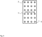
- Fig. 1 shows a block diagram of an embodiment of an antenna array 1, which comprises a number of antenna elements 2, 3. For sake of clarity only the first and the last antenna elements 2, 3 have been provided with a reference sign.
- the antenna array 1 comprises four columns and six lines of antenna elements 2, 3, i.e. a total of 24 antenna elements.
- the single antenna elements 2, 3 are equidistant to each other column-wise and row-wise.
- This antenna array 1 is just an exemplary antenna element.
- Other antenna elements can have any number of antenna elements spaced apparat at any distances.
- Fig. 2 shows a block diagram of an embodiment of a calibration system 4 according to the first aspect of the present invention.
- the calibration system 4 comprises a signal generator 5, which is to the single antenna elements 2, 3 via signal lines, which are shown in Fig. 2 as a signal bus 6.
- the signal bus 6 carries the test signal 7, which the signal generator 5 generates to the single antenna elements 2, 3.
- the signal generator 5 is connected to the antenna elements 2, 3 via a single signal bus 6.
- this bus is just exemplarily drawn as a single line.
- the signal bus 6 can comprise any number of data lines.
- the signal bus 6 can especially comprise a dedicated signal line to each one of the antenna elements 2, 3. This allows the signal generator 5 to drive specific single antenna elements 2, 3 or specific groups of antenna elements 2, 3.
- the signal generator 5 can be indirectly to the antenna elements 2, 3 via a signal-processing device of the antenna array 1 or the device, which carries the antenna array 2, e.g. a smartphone.
- the signal generator 5 may comprise any means, which are capable of generating the respective signal. Such means may e.g. comprise an oscillator to further signal generation devices, like e.g. e PLL or the like. If the signal generator 5 is to a signal processing device as explained above, the signal generator 5 can comprise means for generating a digital data signal, which comprises information about the test signal 7 such that the signal processing device can generate the test signal 7 for the respective antenna elements 2, 3.
- the calibration system 4 further comprises a probe 8, which can be moved at least in two axis, i.e. a plane.
- This plane can especially be parallel to the plane of the antenna array 1.
- the distance between the planes must be small enough for the signals of the single antenna elements 2, 3 to be distinguishable. If the probe moves to far away from the antenna elements 2, 3 the signals of different antenna elements 2, 3 will blend into each other and no exact measurement will be possible.
- any number of probes 8 can be used, which can be positioned either statically to each other or be movable relative to each other, i.e. they can be moved separately. It is obvious that increasing the number of probes 8 will also increase the measurement speed.
- the probe 8 can comprise in one embodiment an antenna (not explicitly shown, see Fig. 3 ) that is tuned to the frequency of the test signal, e.g. 28 GHz.
- the probe 8 can provide the measurement signal 9 comprising a voltage, a current and/or a power.
- the probe 8 and the signal generator 5 are both in bidirectional communication to the position determination unit 10, which in the embodiment of Fig. 2 further incorporates a central control unit of the calibration system 4. That means that the position determination unit 10 can control the signal generator 5 and the probe 8. For example, the position determination unit 10 start the signal generator 5 or move the probe 8 to a specific position.
- the probe 8 will deliver the measurement signals 9 to the position determination unit 10.
- the position determination unit 10 will analyze this measurement signals to determine the exact positions of the antenna elements 2, 3 and output said positions as calibrated positions 11.
- the calibrated positions can e.g. be provided relative to the origin 15 of a predefined coordinate system (see Fig. 3 ).
- the coordinate system can also be known to the device, which carries the antenna array 1. This allows the device to use the calibrated positions 11 to internally calibrate or adjust the stored positions for the single antenna elements 2, 3.
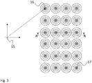
- Fig. 3 shows a diagram of an embodiment of measurement signals 9, which are shown as two-dimensional map.
- the two dimensional map is a kind of contour graph, where the intensity of the measurement signal is represented by the distance of the single contour lines. That means that the measured intensity is higher if the distance of the contour lines is smaller.
- the diagram comprises a local maximum 16, 17 for each one of the antenna elements 2, 3, since at these positions the maximum power can be measured by the probe 8.
- the origin 15 of a coordinate system is shown.
- the measurement values 9 of the probe 8 can all be referenced to the position of the probe 8 relative to the origin 15. This allows easily determining the positions of the maxima 16, 17 in the two-dimensional map relative to the origin 15, i.e. in the respective coordinate system.
- Fig. 4 shows a block diagram of another embodiment of a calibration system 24, which is based on the calibration system 4 of Fig. 2 . Similar elements are provided with similar reference signs as in Fig. 2 but increased by 20.
- the calibration system 24 further comprises a recorder 32, which can comprise signal converters, like e.g. analog-to-digital converters, and a memory that stores the measurement values 29 and the respective positions for later processing by the position determination unit 30.
- a recorder 32 can comprise signal converters, like e.g. analog-to-digital converters, and a memory that stores the measurement values 29 and the respective positions for later processing by the position determination unit 30.
- the calibration system 24 also comprises a motion actuator 33 for moving the probe 28.
- the motion actuator 33 can e.g. be controller by the position determination unit 30.
- the probe 8 comprises an antenna 34 as measurement element.
- Fig. 5 shows flow diagram of an embodiment of a method for calibrating an antenna array 1 comprising a plurality of antenna elements.
- the method comprises generating, S1, a predetermined test signal 7, 27 and providing the test signal 7, 27 to the antenna elements 2, 3.
- the test signal 7, 27 can e.g. be provided to all antenna elements 2, 3 at the same time.
- the test signal 7, 27 can be provided consecutively to the antenna elements 2, 3 one by one or group by group.
- the test signal 7, 27 can comprising a radio frequency, RF, signal of a predetermined frequency, which can be directly fed into the antenna elements 2, 3.
- the test signal 2, 27 can comprise a digital command signal for a transceiver of the antenna array 1, which commands the transceiver to drive the single antenna elements 2, 3 with a radio frequency, RF, signal of a predetermined frequency.
- At least one physical parameter is measured, S2, with a number of probes 8, 28, which is influenced by emissions of the antenna elements 2, 3.
- Respective measurement signals 9, 29 are then analyzed to determine, S3, the positions of the antenna elements 2, 3 as calibrated positions 11, 31.
- determining the positions of the antenna elements 2, 3, these can be determined based on maxima of the measurement signals 9, 29 and the positions of the respective maxima.
- the method can therefore further comprise moving relatively to each other the probes 8, 28 and the antenna array 1, and recording the measurement signals 9, 29 together with the respective positions of the probes 8, 28.
- the probes 8, 28 can e.g. be moved in a first plane that is parallel to a second plane, in which the antenna elements 2, 3 lie. That means that the probes 8, 28 are moved in front of the antenna array 1 and perform a kind of scan of the surface of the antenna array 1.
- the probes 8, 28 can also be moved in a plurality of third planes that are parallel to the first plane and each distanced apart from the prior plane by a predetermined distance. This means that a three-dimensional scan is performed in various planes or layers.
- the probes 8, 28 can be moved to estimated start positions, which are estimated to lie in front of respective antenna elements 2, 3 prior to starting the analysis.
- the probes 8, 28 can then be moved in a pre-defined zone until a maximum measurement value 9, 29 is identified.
- the probes 8, 28 can e.g. comprise a measurement element 34, like e.g. an antenna, for measuring the value of the physical parameter.
- a measurement element 34 like e.g. an antenna, for measuring the value of the physical parameter.
- Such an antenna 34 can be adapted to the frequency of the test signal 7, 27.
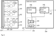
- Fig. 6 shows a block diagram of an embodiment of a calibration system 100 for a RF device 150.
- the RF device comprises three of signal paths 151, 152, 153, wherein this number is just exemplary and more or less signal paths are possible (hinted at by three dots).
- Every signal path 151, 152, 153 in this example comprises a transmit signal chain consisting of an amplifier 155, an optional phase shifter 156, and an antenna element 158.
- the same antenna element 158 also serves the receive signal chain, which comprises the antenna element 158, an optional phase shifter or filter 11, and an amplifier 12.
- the signals of the transmit and the receive signal chains are separated by a circulator 157. For sake of simplicity, only the elements of the first signal path 151 are provided with reference signs.
- the signal paths 151, 152, 153 are connected to a transceiver 154 of the RF device 150, which drives the transmit signal chains and receives signals from the receive signal chains. It is understood, that this arrangement of the RF device 150 is just exemplary and serves to explain the present invention. However, the present invention can be used with any other RF device.
- the calibration system 100 comprises a measurement system 101, which serves to measure the signals emitted by the antenna elements 158 or to transmit test signals 107 to the antenna elements 158. If the signals emitted by the antenna elements 158 are measured, e.g. a probe 102 of the measurement system 101 can detect the signals, while a signal generator 103 generated a test signal 107 and transmits this to the transceiver 154 for driving the signal paths 151, 152, 153.
- the test signal 107 can comprise a digital command signal for the transceiver 154 of the RF device 150, which commands the transceiver 154 to drive the single signal paths 151, 152, 153 with a radio frequency, RF, signal of a predetermined frequency and/or to set the amplifiers of the single signal paths 151, 152, 153 to a predetermined nominal, e.g. the maximum, gain factors.
- a digital command signal for the transceiver 154 of the RF device 150 which commands the transceiver 154 to drive the single signal paths 151, 152, 153 with a radio frequency, RF, signal of a predetermined frequency and/or to set the amplifiers of the single signal paths 151, 152, 153 to a predetermined nominal, e.g. the maximum, gain factors.
- the probe 102 can however also be used to transmit signals to the antenna elements 158.
- the feedback is provided from the transceiver 154 to the measurement system 101.
- the test signal in this case can e.g. be a RF signal.
- the measurement system 101 can provide a heat map or two-dimensional diagram as shown in Fig. 3 . Therefore, one possible measurement system 101 is the measurement system of Figs. 2 and 4 . Based on the output of the measurement system 101, the determination module 104 will determine the antenna element 158, which provides the lowest output. The magnitude of this output will then serve the correction factor calculator 105 to calculate correction factors 106 for the other signal paths 151, 152, 153. When applied to the signal paths 151, 152, 153 the correction factors 106 will equate the outputs of the signal paths 151, 152, 153, at least regarding output signal strength.
- Fig. 7 shows a diagram of the output of the measurement system 101.
- the lower part of the diagram is a cut through the diagram of Fig. 3 at the cut line A. It can be seen, that for every circle in the diagram of Fig. 3 , i.e. every antenna element, there is a local maximum in the diagram of Fig. 7 .
- the abscissa of diagram shows the location in X direction, the ordinate of the diagram shows the power (or any value that refers to the power of the respective signal, e.g. a voltage, a current or the like.
- the threshold line thr defines a minimum value, which all antenna elements or signal paths 151, 152, 153 have to surpass. If any one of the signal paths 151, 152, 153 does not surpass this threshold thr, the RF device is marked as defective.
- the minimum line min refers to the power level of the signal path 151, 152, 153 that provides the lowest power level. That means that this minimum power level min is the basis for later calculating the correction factors 106, 126.
- Fig. 8 shows a block diagram of another embodiment of a calibration system 120, which is based on the calibration system 100 of Fig. 6 . Similar elements are provided with similar reference signs as in Fig. 6 but increased by 20.
- the determination module 124 comprises a function 127 to search all local maxima as shown in Fig. 7 and a function 128 to compare the local maxima to find the maximum with the lowest value. This value is the provided to the correction factor calculator 125, which comprises another function 129 to calculate based on the magnitude of the minimal maximum the correction factors 126 for all signal paths 151, 152, 153.
- the calibration system 120 further comprises a verification unit 130 with a memory 131 and a function 132 that serves for verifying if all the signal paths 151, 152, 153 provide signals with at least the minimum power min.
- the value of min can e.g. be set by a user of the calibration system 120. If any one of the signal paths 151, 152, 153 provides a signal lower than the minimum power min, the verification unit 130 will output a warning signal 133.
- the calibration systems 100, 120 can be implemented in hardware, software or any combination therefore. Parts of the calibration systems 100, 120 can e.g. also be implemented in a configurable logic element, like e.g. a CPLD or FPGA.
- Fig. 9 shows flow diagram of an embodiment of a method for calibrating a radio frequency, RF, device 150 comprising a plurality of signal paths 151, 152, 153.
- Each signal path 151, 152, 153 comprises at least an amplifier 155 and an antenna element 158.
- the method comprises driving S101 the signal paths 151, 152, 153 with a predetermined test signal 107, 134 and measuring an output of the signal paths 151, 152, 153 in response to the test signal 107, 134.
- a physical parameter can be measured, which is influenced by emissions of the antenna elements 158 in response to the test signal 107, 134, in front of the antenna elements 158 as the output.
- the test signal 107, 134 can drive the signal paths 151, 152, 153 to a predetermined nominal, especially the maximum, gain level.
- the test signal 107, 134 can comprise a radio frequency, RF, signal of a predetermined frequency.
- the test signal 107, 134 can comprise a digital command signal for the transceiver 154 of the RF device 150, which commands the transceiver 154 to drive the single signal paths 151, 152, 153 with a radio frequency, RF, signal of a predetermined frequency and/or to set the amplifiers 155 of the single signal paths 151, 152, 153 to a predetermined nominal gain factor.
- a first signal path 151, 152, 153, of which the antenna element 158 provides the lowest output of all antenna elements 158 is identified 102. This can be done e.g. by identifying the values of the measurement data, which represent measurements in front of the positions of the antenna elements 158 and comparing the values of the measurement data, to determine the first signal path 151, 152, 153 with the lowest output.
- a correction factor 126 for the further signal paths 151, 152, 153 is calculated 103, such that with the applied correction factor 126 the output of all signal paths 151, 152, 153 is equal within a predetermined acceptance interval.
- Calculating 103 can comprise dividing the lowest output value, which represents the first signal path 151, 152, 153, by the output value, which represents a respective other one of the signal paths 151, 152, 153.
- the correction factors 126 can be provided as gain factors for the amplifiers of the respective signal paths 151, 152, 153.
- the correction factors 126 can e.g. be provided as digital values to a transceiver 154 or any signal-processing unit of the RF device 150, which drives the signal paths 151, 152, 153.
- the method can also comprise verifying that all signal paths 151, 152, 153 provide an output, which is larger than a predetermined minimum output.
- Fig. 10 shows a block diagram of a calibration system 200 for calibrating a radio frequency, RF, device 150 as already explained regarding Fig. 6 .
- the RF device 150 comprises a plurality of signal paths 151, 152, 153.
- Each signal path 151, 152, 153 comprises at least an amplifier 155, 12 and an antenna element 158.
- the calibration system 200 comprises a signal generator 201 for driving the signal paths 151, 152, 153 with a predetermined test signal 202.
- the test signal 202 can e.g. comprise a radio frequency, RF, signal, which can be provided to internal connectors of the RF device 150 for driving the signal paths 151, 152, 153 with the RF signal. This serves for testing the transmit signal chains.
- the RF signal can also be provided to probes 203, 204 of the calibration system 200, e.g. antennas, for transmitting the test signal 202 to the respective antenna elements 158 of the respective signal paths 151, 152, 153 for testing the receive signal chains.
- the signal generator 201 can provide a first sub-signal of the RF signal to the probes 203, 204 for transmitting the test signal 202 to the respective antenna elements of the respective signal paths 151, 152, 153.
- the signal generator 201 can further provide a second sub-signal of the RF signal to the RF device 154 for driving the signal paths 151, 152, 153 with the RF signal.
- the signal generator 201 can generate the test signal 202, or at least the second sub-signal comprising a digital command signal for a transceiver 154 of the RF device 150, which commands the transceiver 154 to drive the single signal paths 151, 152, 153 with a radio frequency, RF, signal of a predetermined frequency.
- the calibration system 200 further comprises at least two probes 203, 204 for measuring the output of the signal paths 151, 152, 153 in reaction to the test signal 202. If the probes 203, 204 are used for transmitting a RF signal to the RF device 150, the output of the signal paths can be provided by the transceiver 154 to the calibration system 200.
- the calibration system 200 can also comprise a correction factor calculator 205 for calculating respective correction factors 206 based on differences in at least one characteristic of the measured outputs of the signal paths 151, 152, 153.
- the characteristics of the measured outputs can comprise a phase and/or an amplitude and/or a frequency and/or a timing of the outputs. That means that the correction factor 206 can be calculated based on a difference in phase of the measured outputs, based on a difference in amplitude of the measured outputs, and/or based on a difference in frequency and/or timing of the measured outputs.
- the correction factor calculator 205 can provide the correction factors 206 directly to elements of the respective signal paths 151, 152, 153. As an alternative, the correction factor calculator 205 can provide the correction factors 206 as digital values to a signal-processing unit, e.g. the transceiver 154, of the RF device 150, which drives the signal paths 151, 152, 153.
- a signal-processing unit e.g. the transceiver 154
- Fig. 11 shows a block diagram of another embodiment of a calibration system 220, which is based on the calibration system 200 of Fig. 10 . Similar elements are provided with similar reference signs as in Fig. 10 but increased by 20.
- the probes 223, 224 are spaced apart from each other by a predetermined distance which defines an exclusion zone 228, 229.
- the predetermined distance can e.g. define a distance between the apertures of two probes 223, 224 or antennas 223, 224.
- the predetermined distance can especially be at least 0.4 times the wavelength of the test signal 222.
- Fig. 12 shows flow diagram of a calibration method for calibrating a radio frequency, RF, device 150 comprising a plurality of signal paths 151, 152, 153, each signal path 151, 152, 153 comprising at least an amplifier 155 and an antenna element 158.
- the method comprises driving S201 the signal paths 151, 152, 153 with a predetermined test signal 202.
- the test signal 202 can e.g. comprise a radio frequency, RF, signal.
- the RF signal can e.g. be provided to internal connectors of the RF device 150 for driving the signal paths 151, 152, 153 with the RF signal.
- the RF signal can also be provided to the probes 203, 204 for transmitting the test signal 202 to the respective antenna elements 158 of the respective signal paths 151, 152, 153.
- a first sub-signal of the RF signal can be provided to the probes 203, 204 for transmitting the test signal 202 to the respective antenna elements 158 of the respective signal paths 151, 152, 153.
- a second sub-signal of the RF signal can be provided to the RF device 150 for driving the signal paths 151, 152, 153 with the RF signal.
- the test signal 202 can also be generated as a digital command signal for a digital signal-processing unit, e.g. a transceiver 154, of the RF device 150, which commands the transceiver 154 to drive the single signal paths 151, 152, 153 with a radio frequency, RF, signal of a predetermined frequency.
- a digital signal-processing unit e.g. a transceiver 154
- RF device 150 e.g. a radio frequency
- the output of the signal paths 151, 152, 153 is measured S202 in reaction to the test signal 202 with at least two probes 203, 204.
- the probes 203, 204 can be spaced apart from each other by a predetermined distance, which defines an exclusion zone.
- the predetermined distance can be based on a distance between the apertures of the two probes 203, 204 and comprise at least 0.4 times the wavelength of the test signal 202.
- Respective correction factors 206, 226 are then calculated S203 based on differences in at least one characteristic of the measured outputs of the signal paths 151, 152, 153.
- the characteristics of the measured outputs can comprise a phase, an amplitude, a frequency and/or a timing of the outputs.
- the respective correction factors 206, 226 can therefore be calculated based on a difference in phase of the measured outputs, based on a difference in amplitude of the measured outputs, and/or based on a difference in frequency and/or timing of the measured outputs.
- the calculated correction factors 206, 226 can then be provided directly to elements of the respective signal paths 151, 152, 153. This means that the correction factors 206, 226 directly influence the elements of the respective signal paths 151, 152, 153. For example, parameters of a phase shifter 156 and/or an amplifier 155 can be set accordingly.
- the calculated correction factors 206, 226 can e.g. be provided as digital values to a signal-processing unit, e.g. transceiver 154 of the RF device 150, which drives the signal paths 151, 152, 153.
- the transceiver can then pre-process the respective driving signals according to the correction factors 206, 226 or set the parameters in the respective elements.
Landscapes
- Physics & Mathematics (AREA)
- Electromagnetism (AREA)
- Engineering & Computer Science (AREA)
- Computer Networks & Wireless Communication (AREA)
- Signal Processing (AREA)
- Variable-Direction Aerials And Aerial Arrays (AREA)
Abstract
Description
- The invention relates to calibration systems and methods for calibrating antenna arrays and RF devices.
- Although applicable to any system that uses wireless signals, the present invention will be described in combination with testing of wireless communication devices.
- Modern wireless communication devices use radio frequency signal to transmit data and or speech. Manufacturers of such communication devices always try to improve the efficiency of the communication devices and at the same time have to fulfil legal or regulatory regulations.
- Therefore, extensive testing of such communication devices is performed during development, production and after production. Such testing serves quality assurance and compliance tests.
- There is a need for improved testing of wireless devices.
- In a first aspect, the invention provides a calibration system for calibrating an antenna array comprising a plurality of antenna elements, i.e. two or more antenna elements. The system comprises a signal generator for generating a predetermined test signal and, the signal generator being configured to provide the test signal to the antenna elements, a number of probes, i.e. one or more probes, for measuring at least one physical parameter, which is influenced by emissions or receptions of the test signal by the antenna elements, and providing respective measurement signals, and a position determination unit for determining based on the measurement signals the positions of the antenna elements as calibrated positions.
- In modern communication systems, like e.g. smartphone or other mobile equipment, especially so called 5G equipment, antenna arrays can be used to provide compact antenna systems. Such antenna arrays can perform beam forming and are therefore advantageous for improving the signal quality or signal strength in mobile data communications.
- Small deviations of the positions of the antenna elements by e.g. just 0.2 mm would already comprise a deviation of 20% or more of the wavelength especially at millimeter wave frequencies. Such deviations can therefore strongly influence the quality of the beamforming in such devices.
- Especially with increasing frequencies and therefore smaller wavelengths in the range of 1 mm or less, it is therefore important to exactly know the positions of the single antenna elements of such an antenna array.
- Since in most applications the mobile device will have a cover or the antenna array will comprise a protective sheet or layer, it is difficult or impossible to determine the positions optically.
- The present invention therefore provides a test signal to the antenna array, which drives the antenna elements to emit an electromagnetic signal, which is then measured as the physical variable by the probes. Or the present invention provides a test signal to the probes to emit an electromagnetic signal, which is received by the antenna array, i.e. the antenna elements, and which is then measured as the physical variable. This can e.g. be performed by a transceiver in a device which carries the antenna array or by a dedicated measuring device, which is coupled to the antenna array for the measurement.
- Based on the respective measurement signals the position determination unit will determine positions of the single antenna elements. The position determination unit can e.g. determine the relative positions of the antenna elements, i.e. the positions of the antenna elements relative to an origin of a predetermined coordinate system.
- The determined positions can then just exemplarily be provided to the device under test, DUT, i.e. the respective smartphone or the like, which can then calibrate its transceiver accordingly. The determined positions can also be used by test equipment e.g. in an end of line verification after production of the respective device. To support such end of line tests, the calibration system can also store a serial number of the single DUTs in order to match a set of positions to the respective DUT.
- In one embodiment, the calibration system can further comprise a motion actuator for moving relative to each other the probes and the antenna array, and a recorder for recording the measurement signals together with the respective positions of the probes. Moving the probes and the antenna array relative to each other means that either the probes can be moved, the antenna array can be moved or both can be moved.
- By moving the probes and the antenna elements relatively to each other detailed measurements of the physical variable can be performed, which at least for the most part or even completely cover the space in front of the antenna elements.
- In one embodiment, the position determination unit can identify the positions of the antenna elements based on maxima of the measurement signals and the positions of the respective maxima. By measuring the physical variable in front of the antenna elements, the probes will acquire higher values for the measurement signals when the respective probe is directly in front of the respective antenna element. The farther away the probe moves from the antenna element, the lower will be the acquired value of the measurement signal. Therefore, using the maxima of the measurement signal to identify the positions of the antenna elements provides a simple method for identifying the positions.
- It is understood, that the distance of the points at which the probes measure the physical variable is chosen according to the desired resolution of the position determination. That means that the distance is at maximum as large as the desired resolution, i.e. between 0.01 mm and 1.0 mm, e.g. 0.05 mm or 0.1 mm.
- In one embodiment, the position determination unit can identify the positions of the antenna elements based on positions of the shifts, at which 1 D or 2D auto-correlations of a magnitude pattern of the measured signals provide maxima.
- In one embodiment, the position determination unit can identify the positions of the antenna elements based on a two dimensional Fourier series or Fourier Transform together with a measurement heatmap of the measured signals.
- In one embodiment, the motion actuator can move relative to each other the probes and the antenna array such that the probes move in a first plane that is parallel to a second plane, in which the antenna elements lie. The distance between the planes is ideally chosen small enough for differentiating the signals of the single antenna elements in the resulting measurement signal. The relative movement can especially be performed such the probes cover the antenna array sufficiently to measure the physical parameter for every single antenna element. The result can e.g. be a two dimensional matrix, where every matrix element identifies a probe position, while the value of the respective matrix element represents the value of the respective measurement signal. Such a matrix can also be called heat map. This term becomes obvious if the matrix is displayed as a two-dimensional diagram, in which higher values are displayed with increasingly more intense red colors, while lower values can e.g. be displayed with green or blue colors.
- In one embodiment, the motion actuator can move relatively to each other the probes and the antenna array such that the probes move in a plurality of third planes that are parallel to the first plane and each distanced apart from the prior plane by a predetermined distance. The motion actuator will therefore move the probes in a three dimensional space, which lies directly over or in front of the antenna elements. The measurements performed with such a movement, will result in a three dimensional matrix or heat map, which comprises cone or funnel shaped structures, corresponding to the positions of the antenna elements.
- The motion actuator can e.g. comprise electric motors and respective mechanical guides, fixtures and the like for affixing the probes and or the DUT. The motion actuator can e.g. comprise a portal arrangement as e.g. used in milling machines or 3D printer. An alternate arrangement could e.g. be a delta printer like arrangement. Alternatively, an X-Y-moving plate can be provided. It is understood that these arrangements are mere examples and that any other arrangement can be used.
- In one embodiment, the motion actuator can move the probes to estimated start positions, which are estimated to lie in front of respective antenna elements and further moves the probes in a pre-defined zone until a maximum measurement value is identified. This means that the motion actuator can perform a kind of spatially limited search for the maximum at and around the estimated positions of the single antenna elements. The pre-defined zone can e.g. be as large as the antenna elements plus the position tolerances of the antenna elements. It is understood that any other size can be chosen for the pre-defined zone.
- In one embodiment, the signal generator can provide the test signal to all antenna elements at the same time. This means that all antenna elements radiate a respective signal at the same time. If more than one probe is used, a quick measurement can be performed, if the probes are e.g. moved line-wise in front of the antenna array and all antenna elements radiate a signal.
- In one embodiment, the signal generator can consecutively provide the test signal to the antenna elements one by one, or provide the test signal to pairs of the antenna elements or to at least three of the antenna elements at the same time. During the measurement, only one antenna element will therefore be active at a given time. The respective measurement signals will therefore not be influenced by neighboring antenna elements and the distinction between single antenna elements will be improved.
- It is understood, that the signal generator can also drive the single antenna elements in any adequate pattern to mitigate the mutual influence between neighboring antenna elements and at the same time improve the measurement speed by measuring more than one antenna element at a time.
- In one embodiment, the signal generator can generate the test signal comprising a radio frequency, RF, signal of a predetermined frequency.
- The signal generator in this case can directly drive the single antenna elements. This is especially useful for DUTs, which comprise a test connector to the antenna elements.
- In one embodiment, the signal generator can generate the test signal comprising a digital command signal for a transceiver of the antenna array, which commands the transceiver to drive the single antenna elements with a radio frequency, RF, signal of a predetermined frequency. The signal generator in this case can instruct DUTs, which do not comprise a dedicated connector to the antenna elements, to generate the test signal as needed.
- In one embodiment, the probes can comprise a measurement element for measuring the value of the physical parameter and/or electromagnetic signals. Further, the probes can comprise a transmitting element for transmitting the predetermined test signal and/or electromagnetic signals. Also a single element, like e.g. an antenna, can be provided as receiving and transmitting element.
- In one embodiment, the measurement element can comprise an antenna.
- In one embodiment, the antenna can be adapted to the frequency of the test signal. This means that the antenna's frequency range or band is tuned to the test signal.
- In one embodiment, the measurement signal can comprise a voltage and/or a current and/or a power and/or a phase of the measured physical parameter.
- In one embodiment, the physical parameter can comprise an electric field and/or a magnetic field and/or an electromagnetic field.
- It is understood that the above embodiments of the first aspect can mutatis mutandis be implemented in a respective calibration method. It is further understood, that the elements of the calibration system can be implemented in hardware, software, hardware description, e.g. in a CPLD or FPGA, or any combination of the above. Further, the calibration method can also be implemented at least partially in a computer, i.e. as a computer implemented method.
- In a second aspect a calibration system for calibrating a radio frequency, RF, device comprising a plurality of signal paths, each signal path comprising at least an amplifier and an antenna element, is provided. The system comprises a measurement system for driving the signal paths with a predetermined test signal and measuring an output of the signal paths in response to the test signal, a determination module for determining a first signal path, of which the antenna element provides the lowest output of all antenna elements, and a correction factor calculator for calculating based on output of the first signal path a correction factor for the further signal paths such that with the applied correction factor the output of all signal paths is equal within a predetermined acceptance interval.
- Just exemplarily the measurement system can be a or part of a calibration system according to claim 1 or any one of its dependent claims. However, the measurement system can be any system that is capable of driving the signal paths and measuring the outputs accordingly. Usually it will be necessary for the measurement system to know the exact positions of the antenna elements. The positions of the single antenna elements can e.g. be determined with a calibration system according to claim 1 or any one of its dependent claims. However, the positions of the single antenna elements can also be provided by any other means.
- With the predetermined test signal, all the signal paths should provide the same output, i.e. a signal with the same output power. However, due to tolerances in the single elements of the signal paths, the single signal paths will provide different outputs. Especially when the antenna array is used for beamforming, such deviations in the output power of the single signal paths can deteriorate the quality of the beam-formed signal.
- The calibration system mitigates these negative effects by providing a calibration of the single signal paths, such that with the same nominal input signal all signal paths provide the same output. As a basis for the calibration, the signal path with the lowest output is used and the correction factors are calculated in relation to this lowest output.
- When these correction factors are applied to the signal paths, with the same nominal input signal the output will be equal within an acceptable range or acceptance interval.
- In one embodiment, the measurement system can measure a physical parameter, which is influenced by emissions of the antenna elements in response to the test signal, in front of the antenna elements as the output and provides respective measurement values. The measurement data can e.g. be provided in the form of a two-dimensional or three-dimensional matrix, where every matrix element identifies a position in front of the antenna array, while the value of the respective matrix element represents the measured value of the physical parameter measured at the respective position.
- In one embodiment, the determination module can comprise an identification unit, for identifying the values of the measurement data, which represent measurements in front of the positions of the antenna elements. That means the values of the measurement data, which represent the single signal paths.
- The determination module can e.g. analyze the output for the single signal paths and determine the respective maximum values.
- In one embodiment, the determination module can comprise a comparator, which is configured to compare the values of the measurement data, to determine the first signal path.
- In one embodiment, the correction factor calculator can comprise a divider for dividing the lowest output value, which represents the first signal path, by the output value, which represents a respective other one of the signal paths, for calculating the correction factor for said other signal path.
- In one embodiment, the calibration system can further comprise a verification unit for verifying that all signal paths provide an output, which is larger than a predetermined minimum output. With the predetermined test signal, every signal path should provide - within certain tolerances - a similar output. Is a single signal paths provides a significantly lower output, that signal path may be defective. The verification unit therefore serves to verify correct functionality of the signal paths and to identify faulty RF devices. The required minimum output can e.g. be set by a user.
- In one embodiment, the test signal can drive the signal paths to a predetermined nominal power level. The nominal power level regarding the present patent application is a power level, which is set by the DUT as commanded for all signal paths. That means that in terms of the DUT the output of all signal paths should be the same. However, as already explained above, tolerances can lead to different outputs of the different signal paths. If all the signal paths are driven to the same nominal power level, it is easy to identify deviations of the single signal paths.
- In one embodiment, the test signal can set the amplifiers of the signal paths all to the same nominal gain value.
- In one embodiment, the test signal can drive the signal paths to a predetermined maximum power level.
If the signal paths are driven to their respective maximum power level, the weakest signal path can easily be identified. - In one embodiment, the test signal can comprise a radio frequency, RF, signal of a predetermined frequency. This is especially useful for RF devices, which comprise a test connector to the antenna elements.
- In one embodiment, the test signal can comprise a digital command signal for a transceiver of the RF device, which commands the transceiver to drive the single signal paths with a radio frequency, RF, signal of a predetermined frequency and/or to set the amplifiers of the single signal paths to a predetermined nominal gain factors. The signal generator in this case can instruct RF devices, which do not comprise a dedicated connector to the antenna elements, to generate the test signal as needed.
- In one embodiment, the correction factors can be provided as gain factors for the amplifiers of the respective signal paths. This type of correction factors can be used to directly set the gain in the single signal paths without any further signal processing.
- In one embodiment, the correction factors can be provided as digital values to a signal-processing unit of the RF device, which drives the signal paths. If the correction factors are provided as digital values to the signal-processing unit, the signal-processing unit can decide how to use the correction factors. The signal-processing unit can set the gain factors of the single amplifiers in the signal paths. However, as an alternative, the signal-processing unit can also modify, i.e. amplify or attenuate, the signals, which are provided to the single signal paths. This allows using fixed gain amplifiers and at the same time, providing calibrated output signals.
- In one embodiment, the measurement system can transmit the test signal to the antenna elements and receives from the RF device the measured output of the signal paths. When the measurement system drives the signal paths from within the RF device, the calibration system can calibrate the transmitting signal paths of the RF device. However, it the measurement system sends the test signal to the antenna elements wirelessly via e.g. probe antennas, the RF device can internally measure the output of the receiving signal paths and provide the calibration system with the respective output.
- It is understood that the above embodiments of the second aspect can mutatis mutandis be implemented in a respective calibration method. It is further understood, that the elements of the calibration system can be implemented in hardware, software, hardware description, e.g. in a CPLD or FPGA, or any combination of the above. Further, the calibration method can also be implemented at least partially in a computer, i.e. as a computer implemented method.
- In a third aspect, the present invention provides a calibration system for calibrating a radio frequency, RF, device comprising a plurality of signal paths, each signal path comprising at least an amplifier and an antenna element. The system comprises a signal generator for driving the signal paths with a predetermined test signal, at least two probes for measuring the output of the signal paths in reaction to the test signal, and a correction factor calculator for calculating respective correction factors based on differences in at least one characteristic of the measured outputs of the signal paths.
- In modern communication systems, like e.g. smartphone or other mobile equipment, especially so called 5G equipment, antenna arrays can be used to provide compact antenna systems. Such antenna arrays can perform beam forming and are therefore advantageous for improving the signal quality or signal strength in mobile data communications.
- However, the single signal paths in such devices will each comprise tolerances, which will slightly modify the signals while being propagated to the antenna elements. If the signals are then transmitted by the antenna elements e.g. with a phase or a frequency that deviates from the intended signal, the transmitting capabilities and especially the beamforming capabilities may deteriorate.
- With the predetermined test signal being provided to all signal paths, all the signal paths should provide the same output, i.e. a signal with the same phase, the same amplitude, the same frequency and the same timing. However, as already indicated the single elements of the signal paths, in transmitting direction as well as in receiving direction, will comprise tolerances. These tolerances are introduced into the elements during production due to inevitable inaccuracies and size variations. Even though these tolerances may be minute, they will still influence the signal propagation in the respective signal path. Therefore, the single signal paths will provide different outputs, when provided with the same input signal, i.e. the test signal.
- Especially, when the antenna array is used for beamforming, such deviations in the output power and phase of the single signal paths can deteriorate the quality of the beam-formed signal. The calibration system mitigates these negative effects by providing a calibration of the single signal paths. Calibration in this context refers to a modification or configuration of elements of the signal paths or the signal generation, such that the differences caused by the tolerances in the signal paths are balanced.
- The use of at least two probes, i.e. antennas, allows analyzing the single measured outputs and especially the differences between the measured outputs in real time and in more depth than if the outputs where analyzed separately.
- In one embodiment, the characteristics of the measured outputs can comprise a phase and/or an amplitude and/or a frequency and/or a timing of the outputs.
- In one embodiment, the correction factor calculator can calculate the correction factor based on a difference in phase of the measured outputs.
- In one embodiment, the correction factor calculator can calculate the correction factor based on a difference in amplitude of the measured outputs.
- In one embodiment, the correction factor calculator can calculate the correction factor based on a difference in frequency and/or timing of the measured outputs.
- In one embodiment, the correction factor calculator can provide the correction factors directly to elements of the respective signal paths. This type of correction factors can be used to directly set e.g. the gain, a phase shift and/or a frequency in the single signal paths without any further signal processing. The signal paths can e.g. comprise configurable phase shifters or the like, which can be configured. It is understood, that directly configured refers to setting parameters of elements of the signal chain as opposed to perform signal-processing calculations. This means that the correction factors can also be provided to any kind of processing unit in the RF device, which configures the correction factors in the respective elements.
- In one embodiment, the correction factor calculator can provide the correction factors as digital values to a signal-processing unit of the RF device, which drives the signal paths. The signal-processing unit opposed to the above can modify, i.e. amplify or attenuate, the signals, which are provided to the single signal paths via signal processing calculations. This allows using fixed gain amplifiers or other fixed elements in the signal paths and at the same time providing calibrated output signals.
- In one embodiment, the signal generator can generate the test signal comprising a radio frequency, RF, signal. The RF signal can have a predetermined frequency or timing, a predetermined phase and/or a predetermined amplitude. This kind of test signal is especially useful for RF devices, which comprise a test connector to the antenna elements.
- In one embodiment, the signal generator can provide the RF signal to internal connectors of the RF device for driving the signal paths with the RF signal. The signal generator in this case can instruct RF devices, which do not comprise a dedicated connector to the antenna elements, to generate the test signal as needed.
- In one embodiment, the signal generator can provide the RF signal to the probes for transmitting the test signal to the respective antenna elements of the respective signal paths. If the test signal is transmitted wirelessly to the antenna elements by the probes, the receiving signal path of the respective antenna element can be analyzed. The output can e.g. be provided to the calibration system by the RF device via digital interface.
- In one embodiment, the signal generator can provide a first sub-signal of the RF signal to the probes for transmitting the test signal to the respective antenna elements of the respective signal paths, and wherein the signal generator provides a second sub-signal of the RF signal to the RF device for driving the signal paths with the RF signal. The first and the second sub-signals e.g. both comprise different frequencies. As an alternative, the first and the second sub-signals can be interleaved in a timely fashion. This allows testing the sending and the receiving parts of the signal paths at the same time.
- In one embodiment, the signal generator can generate the test signal comprising a digital command signal for a transceiver of the RF device, which commands the transceiver to drive the single signal paths with a radio frequency, RF, signal of a predetermined frequency. The signal generator in this case can instruct RF devices, which do not comprise a dedicated connector to the antenna elements, to generate the test signal as needed.
- In one embodiment, the probes can be spaced apart from each other by a predetermined distance, which defines an exclusion zone. The distance between the probes makes sure that no mutual influences falsify the measurements.
- In one embodiment, the predetermined distance can define a distance between the apertures of two probes.
- In one embodiment, the predetermined distance can be at least 0.4 times the wavelength of the test signal, especially of the test signal in the material that comprises more than 50% of the space between the probes.
- It is understood that the above embodiments of the third aspect can mutatis mutandis be implemented in a respective calibration method. It is further understood, that the elements of the calibration system can be implemented in hardware, software, hardware description, e.g. in a CPLD or FPGA, or any combination of the above. Further, the calibration method can also be implemented at least partially in a computer, i.e. as a computer implemented method.
- For a more complete understanding of the present invention and advantages thereof, reference is now made to the following description taken in conjunction with the accompanying drawings. The invention is explained in more detail below using exemplary embodiments, which are specified in the schematic figures of the drawings, in which:
-
Fig. 1 shows a diagram of an embodiment of an antenna array; -
Fig. 2 shows a block diagram of an embodiment of a calibration system according to the present invention; -
Fig. 3 shows a diagram of an embodiment of measurement signals according to an embodiment of the present invention; -
Fig. 4 shows a block diagram of another embodiment of a calibration system according to the present invention; -
Fig. 5 shows flow diagram of an embodiment of a method according to the present invention; -
Fig. 6 shows a block diagram of another embodiment of a calibration system according to the present invention; -
Fig. 7 shows a diagram of an embodiment of measurement signals according to an embodiment of the present invention; -
Fig. 8 shows a block diagram of another embodiment of a calibration system according to the present invention; -
Fig. 9 shows flow diagram of another embodiment of a method according to the present invention; -
Fig. 10 shows a block diagram of another embodiment of a calibration system according to the present invention; -
Fig. 11 shows a block diagram of another embodiment of a calibration system according to the present invention; and -
Fig. 12 shows flow diagram of another embodiment of a method according to the present invention. -
Fig. 1 shows a block diagram of an embodiment of an antenna array 1, which comprises a number ofantenna elements last antenna elements - The antenna array 1 comprises four columns and six lines of
antenna elements single antenna elements -
Fig. 2 shows a block diagram of an embodiment of acalibration system 4 according to the first aspect of the present invention. Thecalibration system 4 comprises asignal generator 5, which is to thesingle antenna elements Fig. 2 as asignal bus 6. Thesignal bus 6 carries thetest signal 7, which thesignal generator 5 generates to thesingle antenna elements Fig. 2 , thesignal generator 5 is connected to theantenna elements single signal bus 6. However, this bus is just exemplarily drawn as a single line. In fact, thesignal bus 6 can comprise any number of data lines. Thesignal bus 6 can especially comprise a dedicated signal line to each one of theantenna elements signal generator 5 to drive specificsingle antenna elements antenna elements signal generator 5 can be indirectly to theantenna elements antenna array 2, e.g. a smartphone. - The
signal generator 5 may comprise any means, which are capable of generating the respective signal. Such means may e.g. comprise an oscillator to further signal generation devices, like e.g. e PLL or the like. If thesignal generator 5 is to a signal processing device as explained above, thesignal generator 5 can comprise means for generating a digital data signal, which comprises information about thetest signal 7 such that the signal processing device can generate thetest signal 7 for therespective antenna elements - The
calibration system 4 further comprises aprobe 8, which can be moved at least in two axis, i.e. a plane. This plane can especially be parallel to the plane of the antenna array 1. The distance between the planes must be small enough for the signals of thesingle antenna elements antenna elements different antenna elements probes 8 can be used, which can be positioned either statically to each other or be movable relative to each other, i.e. they can be moved separately. It is obvious that increasing the number ofprobes 8 will also increase the measurement speed. - The
probe 8 can comprise in one embodiment an antenna (not explicitly shown, seeFig. 3 ) that is tuned to the frequency of the test signal, e.g. 28 GHz. Theprobe 8 can provide the measurement signal 9 comprising a voltage, a current and/or a power. - The
probe 8 and thesignal generator 5 are both in bidirectional communication to theposition determination unit 10, which in the embodiment ofFig. 2 further incorporates a central control unit of thecalibration system 4. That means that theposition determination unit 10 can control thesignal generator 5 and theprobe 8. For example, theposition determination unit 10 start thesignal generator 5 or move theprobe 8 to a specific position. - The
probe 8 will deliver the measurement signals 9 to theposition determination unit 10. Theposition determination unit 10 will analyze this measurement signals to determine the exact positions of theantenna elements - The calibrated positions can e.g. be provided relative to the
origin 15 of a predefined coordinate system (seeFig. 3 ). The coordinate system can also be known to the device, which carries the antenna array 1. This allows the device to use the calibratedpositions 11 to internally calibrate or adjust the stored positions for thesingle antenna elements -
Fig. 3 shows a diagram of an embodiment of measurement signals 9, which are shown as two-dimensional map. The two dimensional map is a kind of contour graph, where the intensity of the measurement signal is represented by the distance of the single contour lines. That means that the measured intensity is higher if the distance of the contour lines is smaller. The diagram comprises alocal maximum antenna elements probe 8. - As can be seen, in the diagram the
origin 15 of a coordinate system is shown. The measurement values 9 of theprobe 8 can all be referenced to the position of theprobe 8 relative to theorigin 15. This allows easily determining the positions of themaxima origin 15, i.e. in the respective coordinate system. -
Fig. 4 shows a block diagram of another embodiment of acalibration system 24, which is based on thecalibration system 4 ofFig. 2 . Similar elements are provided with similar reference signs as inFig. 2 but increased by 20. - The
calibration system 24 further comprises arecorder 32, which can comprise signal converters, like e.g. analog-to-digital converters, and a memory that stores the measurement values 29 and the respective positions for later processing by theposition determination unit 30. - The
calibration system 24 also comprises amotion actuator 33 for moving theprobe 28. Although not explicitly shown, themotion actuator 33 can e.g. be controller by theposition determination unit 30. Finally, theprobe 8 comprises anantenna 34 as measurement element. -
Fig. 5 shows flow diagram of an embodiment of a method for calibrating an antenna array 1 comprising a plurality of antenna elements. - The method comprises generating, S1, a
predetermined test signal test signal antenna elements test signal antenna elements test signal antenna elements test signal antenna elements test signal single antenna elements - Further, at least one physical parameter is measured, S2, with a number of
probes antenna elements Respective measurement signals 9, 29 are then analyzed to determine, S3, the positions of theantenna elements positions antenna elements - The method can therefore further comprise moving relatively to each other the
probes probes probes antenna elements probes - The
probes - Instead of or as addition to recording the measurement values 9, 29, the
probes respective antenna elements probes maximum measurement value 9, 29 is identified. - The
probes measurement element 34, like e.g. an antenna, for measuring the value of the physical parameter. Such anantenna 34 can be adapted to the frequency of thetest signal -
Fig. 6 shows a block diagram of an embodiment of acalibration system 100 for aRF device 150. - The RF device comprises three of
signal paths signal path amplifier 155, anoptional phase shifter 156, and anantenna element 158. Thesame antenna element 158 also serves the receive signal chain, which comprises theantenna element 158, an optional phase shifter orfilter 11, and an amplifier 12. The signals of the transmit and the receive signal chains are separated by acirculator 157. For sake of simplicity, only the elements of thefirst signal path 151 are provided with reference signs. Thesignal paths transceiver 154 of theRF device 150, which drives the transmit signal chains and receives signals from the receive signal chains. It is understood, that this arrangement of theRF device 150 is just exemplary and serves to explain the present invention. However, the present invention can be used with any other RF device. - The
calibration system 100 comprises ameasurement system 101, which serves to measure the signals emitted by theantenna elements 158 or to transmittest signals 107 to theantenna elements 158. If the signals emitted by theantenna elements 158 are measured, e.g. aprobe 102 of themeasurement system 101 can detect the signals, while asignal generator 103 generated atest signal 107 and transmits this to thetransceiver 154 for driving thesignal paths - In this case, the
test signal 107 can comprise a digital command signal for thetransceiver 154 of theRF device 150, which commands thetransceiver 154 to drive thesingle signal paths single signal paths - The
probe 102 can however also be used to transmit signals to theantenna elements 158. In such a mode, the feedback is provided from thetransceiver 154 to themeasurement system 101. The test signal in this case can e.g. be a RF signal. - The
measurement system 101 can provide a heat map or two-dimensional diagram as shown inFig. 3 . Therefore, onepossible measurement system 101 is the measurement system ofFigs. 2 and4 . Based on the output of themeasurement system 101, thedetermination module 104 will determine theantenna element 158, which provides the lowest output. The magnitude of this output will then serve thecorrection factor calculator 105 to calculatecorrection factors 106 for theother signal paths signal paths signal paths -
Fig. 7 shows a diagram of the output of themeasurement system 101. The lower part of the diagram is a cut through the diagram ofFig. 3 at the cut line A. It can be seen, that for every circle in the diagram ofFig. 3 , i.e. every antenna element, there is a local maximum in the diagram ofFig. 7 . The abscissa of diagram shows the location in X direction, the ordinate of the diagram shows the power (or any value that refers to the power of the respective signal, e.g. a voltage, a current or the like. - Further, there are two lines drawn in the diagram, a threshold line thr and a minimum line min. The threshold line thr defines a minimum value, which all antenna elements or signal
paths signal paths - The minimum line min refers to the power level of the
signal path -
Fig. 8 shows a block diagram of another embodiment of acalibration system 120, which is based on thecalibration system 100 ofFig. 6 . Similar elements are provided with similar reference signs as inFig. 6 but increased by 20. - In the
calibration system 120, thedetermination module 124 comprises afunction 127 to search all local maxima as shown inFig. 7 and afunction 128 to compare the local maxima to find the maximum with the lowest value. This value is the provided to thecorrection factor calculator 125, which comprises anotherfunction 129 to calculate based on the magnitude of the minimal maximum the correction factors 126 for allsignal paths - The
calibration system 120 further comprises averification unit 130 with amemory 131 and afunction 132 that serves for verifying if all thesignal paths calibration system 120. If any one of thesignal paths verification unit 130 will output awarning signal 133. - It is understood that the
calibration systems calibration systems -
Fig. 9 shows flow diagram of an embodiment of a method for calibrating a radio frequency, RF,device 150 comprising a plurality ofsignal paths signal path amplifier 155 and anantenna element 158. - The method comprises driving S101 the
signal paths predetermined test signal signal paths test signal antenna elements 158 in response to thetest signal antenna elements 158 as the output. Thetest signal signal paths - The
test signal test signal transceiver 154 of theRF device 150, which commands thetransceiver 154 to drive thesingle signal paths amplifiers 155 of thesingle signal paths - Based on the measured output, a
first signal path antenna element 158 provides the lowest output of allantenna elements 158, is identified 102. This can be done e.g. by identifying the values of the measurement data, which represent measurements in front of the positions of theantenna elements 158 and comparing the values of the measurement data, to determine thefirst signal path - Further, based on output of the
first signal path correction factor 126 for thefurther signal paths correction factor 126 the output of allsignal paths - Calculating 103 can comprise dividing the lowest output value, which represents the
first signal path signal paths - The correction factors 126 can be provided as gain factors for the amplifiers of the
respective signal paths transceiver 154 or any signal-processing unit of theRF device 150, which drives thesignal paths - The method can also comprise verifying that all
signal paths -
Fig. 10 shows a block diagram of acalibration system 200 for calibrating a radio frequency, RF,device 150 as already explained regardingFig. 6 . TheRF device 150 comprises a plurality ofsignal paths signal path amplifier 155, 12 and anantenna element 158. - The
calibration system 200 comprises asignal generator 201 for driving thesignal paths predetermined test signal 202. Thetest signal 202 can e.g. comprise a radio frequency, RF, signal, which can be provided to internal connectors of theRF device 150 for driving thesignal paths - The RF signal can also be provided to
probes calibration system 200, e.g. antennas, for transmitting thetest signal 202 to therespective antenna elements 158 of therespective signal paths - If the transmit and the receive signal chains are to be tested at the same time, the
signal generator 201 can provide a first sub-signal of the RF signal to theprobes test signal 202 to the respective antenna elements of therespective signal paths signal generator 201 can further provide a second sub-signal of the RF signal to theRF device 154 for driving thesignal paths - As an alternative, the
signal generator 201 can generate thetest signal 202, or at least the second sub-signal comprising a digital command signal for atransceiver 154 of theRF device 150, which commands thetransceiver 154 to drive thesingle signal paths - The
calibration system 200 further comprises at least twoprobes signal paths test signal 202. If theprobes RF device 150, the output of the signal paths can be provided by thetransceiver 154 to thecalibration system 200. - The
calibration system 200 can also comprise acorrection factor calculator 205 for calculatingrespective correction factors 206 based on differences in at least one characteristic of the measured outputs of thesignal paths correction factor 206 can be calculated based on a difference in phase of the measured outputs, based on a difference in amplitude of the measured outputs, and/or based on a difference in frequency and/or timing of the measured outputs. - The
correction factor calculator 205 can provide the correction factors 206 directly to elements of therespective signal paths correction factor calculator 205 can provide the correction factors 206 as digital values to a signal-processing unit, e.g. thetransceiver 154, of theRF device 150, which drives thesignal paths -
Fig. 11 shows a block diagram of another embodiment of acalibration system 220, which is based on thecalibration system 200 ofFig. 10 . Similar elements are provided with similar reference signs as inFig. 10 but increased by 20. - In
Fig. 11 theprobes exclusion zone probes antennas test signal 222. -
Fig. 12 shows flow diagram of a calibration method for calibrating a radio frequency, RF,device 150 comprising a plurality ofsignal paths signal path amplifier 155 and anantenna element 158. - The method comprises driving S201 the
signal paths predetermined test signal 202. Thetest signal 202 can e.g. comprise a radio frequency, RF, signal. The RF signal can e.g. be provided to internal connectors of theRF device 150 for driving thesignal paths probes test signal 202 to therespective antenna elements 158 of therespective signal paths - Further, a first sub-signal of the RF signal can be provided to the
probes test signal 202 to therespective antenna elements 158 of therespective signal paths RF device 150 for driving thesignal paths - The
test signal 202 can also be generated as a digital command signal for a digital signal-processing unit, e.g. atransceiver 154, of theRF device 150, which commands thetransceiver 154 to drive thesingle signal paths - Then the output of the
signal paths test signal 202 with at least twoprobes - The
probes probes test signal 202. -
Respective correction factors signal paths - The characteristics of the measured outputs can comprise a phase, an amplitude, a frequency and/or a timing of the outputs. The
respective correction factors - The
calculated correction factors respective signal paths respective signal paths phase shifter 156 and/or anamplifier 155 can be set accordingly. - The
calculated correction factors e.g. transceiver 154 of theRF device 150, which drives thesignal paths - Although specific embodiments have been illustrated and described herein, it will be appreciated by those of ordinary skill in the art that a variety of alternate and/or equivalent implementations exist. It should be appreciated that the exemplary embodiment or exemplary embodiments are only examples, and are not intended to limit the scope, applicability, or configuration in any way. Rather, the foregoing summary and detailed description will provide those skilled in the art with a convenient road map for implementing at least one exemplary embodiment, it being understood that various changes may be made in the function and arrangement of elements described in an exemplary embodiment without departing from the scope as set forth in the appended claims and their legal equivalents. Generally, this application is intended to cover any adaptations or variations of the specific embodiments discussed herein.
- In the foregoing detailed description, various features are grouped together in one or more examples or examples for the purpose of streamlining the disclosure. It is understood that the above description is intended to be illustrative, and not restrictive. It is intended to cover all alternatives, modifications and equivalents as may be included within the scope of the invention. Many other examples will be apparent to one skilled in the art upon reviewing the above specification.
- Specific nomenclature used in the foregoing specification is used to provide a thorough understanding of the invention. However, it will be apparent to one skilled in the art in light of the specification provided herein that the specific details are not required in order to practice the invention. Thus, the foregoing descriptions of specific embodiments of the present invention are presented for purposes of illustration and description. They are not intended to be exhaustive or to limit the invention to the precise forms disclosed; obviously many modifications and variations are possible in view of the above teachings. The embodiments were chosen and described in order to best explain the principles of the invention and its practical applications, to thereby enable others skilled in the art to best utilize the invention and various embodiments with various modifications as are suited to the particular use contemplated. Throughout the specification, the terms "including" and "in which" are used as the plain-English equivalents of the respective terms "comprising" and "wherein," respectively. Moreover, the terms "first," "second," and "third," etc., are used merely as labels, and are not intended to impose numerical requirements on or to establish a certain ranking of importance of their objects.
Claims (15)
- A calibration system for calibrating a radio frequency, RF, device comprising a plurality of signal paths, each signal path comprising at least an amplifier and an antenna element, the system comprising:a signal generator for driving the signal paths with a predetermined test signal,at least two probes for measuring the output of the signal paths in reaction to the test signal, anda correction factor calculator for calculating respective correction factors based on differences in at least one characteristic of the measured outputs of the signal paths.
- The calibration system of claim 1, wherein the characteristics of the measured outputs comprise a phase and/or an amplitude and/or a frequency and/or a timing of the outputs.
- The calibration system of claim 2, wherein the correction factor calculator calculates the correction factor based on a difference in phase of the measured outputs; and/or
wherein the correction factor calculator calculates the correction factor based on a difference in amplitude of the measured outputs; and/or
wherein the correction factor calculator calculates the correction factor based on a difference in frequency and/or timing of the measured outputs. - The calibration system of any one of the preceding claims, wherein the correction factor calculator provides the correction factors directly to elements of the respective signal paths; and/or
wherein the correction factor calculator provides the correction factors as digital values to a signal processing unit of the RF device, which drives the signal paths. - The calibration system of any one of the preceding claims, wherein the signal generator generates the test signal comprising a radio frequency, RF, signal; and.
wherein the signal generator especially provides the RF signal to internal connectors of the RF device for driving the signal paths with the RF signal or to the probes for transmitting the test signal to the respective antenna elements of the respective signal paths. - The calibration system of claim 5, wherein the signal generator provides a first sub-signal of the RF signal to the probes for transmitting the test signal to the respective antenna elements of the respective signal paths, and wherein the signal generator provides a second sub-signal of the RF signal to the RF device for driving the signal paths with the RF signal.
- The calibration system of any one of the preceding claims, wherein the signal generator generates the test signal comprising a digital command signal for a transceiver of the RF device, which commands the transceiver to drive the single signal paths with a radio frequency, RF, signal of a predetermined frequency.
- The calibration system of any one of the preceding claims, wherein the probes are spaced apart from each other by a predetermined distance which defines an exclusion zone; and/or
wherein the predetermined distance defines a distance between the apertures of two probes; and/or
wherein the predetermined distance is at least 0.4 times the wavelength of the test signal, especially of the test signal in the material that comprises more than 50% of the space between the probes. - A calibration method for calibrating a radio frequency, RF, device comprising a plurality of signal paths, each signal path comprising at least an amplifier and an antenna element, the method comprising:driving the signal paths with a predetermined test signal,measuring the output of the signal paths in reaction to the test signal with at least two probes, andcalculating respective correction factors based on differences in at least one characteristic of the measured outputs of the signal paths.
- The calibration method of claim 9, wherein the characteristics of the measured outputs comprise a phase and/or an amplitude and/or a frequency and/or a timing of the outputs.
- The calibration method of claim 10, wherein calculating respective correction factors comprises calculating the correction factor based on a difference in phase of the measured outputs; and/or
wherein calculating respective correction factors comprises calculating the correction factor based on a difference in amplitude of the measured outputs; and/or
wherein calculating respective correction factors comprises calculating the correction factor based on a difference in frequency and/or timing of the measured outputs. - The calibration method of any one of the preceding claims 9 - 11, wherein the calculated correction factors are provided directly to elements of the respective signal paths; and/or
wherein the calculated correction factors are provided as digital values to a signal processing unit of the RF device, which drives the signal paths; and/or
comprising generating the test signal comprising a digital command signal for a transceiver of the RF device, which commands the transceiver to drive the single signal paths with a radio frequency, RF, signal of a predetermined frequency. - The calibration method of any one of the preceding claims 9 - 12, comprising generating the test signal comprising a radio frequency, RF, signal;
wherein driving especially comprises providing the RF signal to internal connectors of the RF device for driving the signal paths with the RF signal or to the probes for transmitting the test signal to the respective antenna elements of the respective signal paths. - The calibration method of claim 13, wherein driving comprises providing a first sub-signal of the RF signal to the probes for transmitting the test signal to the respective antenna elements of the respective signal paths, and providing a second sub-signal of the RF signal to the RF device for driving the signal paths with the RF signal.
- The calibration method of any one of the preceding claims 9 - 12, wherein the probes are spaced apart from each other by a predetermined distance which defines an exclusion zone,
wherein the predetermined distance especially defines a distance between the apertures of two probes, and/or wherein the predetermined distance especially is at least 0.4 times the wavelength of the test signal.
Applications Claiming Priority (2)
| Application Number | Priority Date | Filing Date | Title |
|---|---|---|---|
| US201662368362P | 2016-07-29 | 2016-07-29 | |
| US15/384,920 US10148366B2 (en) | 2016-07-29 | 2016-12-20 | Calibration systems and methods |
Publications (2)
| Publication Number | Publication Date |
|---|---|
| EP3276747A1 true EP3276747A1 (en) | 2018-01-31 |
| EP3276747B1 EP3276747B1 (en) | 2019-11-20 |
Family
ID=59350609
Family Applications (1)
| Application Number | Title | Priority Date | Filing Date |
|---|---|---|---|
| EP17177792.3A Active EP3276747B1 (en) | 2016-07-29 | 2017-06-26 | Calibration systems and methods |
Country Status (3)
| Country | Link |
|---|---|
| US (1) | US10148366B2 (en) |
| EP (1) | EP3276747B1 (en) |
| CN (1) | CN107666357B (en) |
Cited By (2)
| Publication number | Priority date | Publication date | Assignee | Title |
|---|---|---|---|---|
| EP3584961A1 (en) * | 2018-06-20 | 2019-12-25 | Rohde & Schwarz GmbH & Co. KG | Test system, test setup and method for calibrating a communication device |
| EP3780421A4 (en) * | 2018-09-04 | 2021-06-16 | Huawei Technologies Co., Ltd. | CALIBRATION PROCESS AND COMMUNICATION DEVICE |
Families Citing this family (12)
| Publication number | Priority date | Publication date | Assignee | Title |
|---|---|---|---|---|
| US20180062260A1 (en) * | 2016-08-26 | 2018-03-01 | Analog Devices Global | Antenna array calibration systems and methods |
| US11177567B2 (en) * | 2018-02-23 | 2021-11-16 | Analog Devices Global Unlimited Company | Antenna array calibration systems and methods |
| TWI678846B (en) | 2018-11-15 | 2019-12-01 | 財團法人工業技術研究院 | Antenna device and method for calibrating antenna device |
| US11349208B2 (en) | 2019-01-14 | 2022-05-31 | Analog Devices International Unlimited Company | Antenna apparatus with switches for antenna array calibration |
| US11404779B2 (en) | 2019-03-14 | 2022-08-02 | Analog Devices International Unlimited Company | On-chip phased array calibration systems and methods |
| EP3748374B8 (en) * | 2019-06-06 | 2023-02-15 | Rohde & Schwarz GmbH & Co. KG | System and method for calibrating radio frequency test chambers |
| US11428732B2 (en) * | 2019-08-28 | 2022-08-30 | Keysight Technologies, Inc. | Self-calibrating deskew fixture |
| US11450952B2 (en) | 2020-02-26 | 2022-09-20 | Analog Devices International Unlimited Company | Beamformer automatic calibration systems and methods |
| US11231458B2 (en) * | 2020-05-15 | 2022-01-25 | Rohde & Schwarz Gmbh & Co. Kg | System and method for aligning a measurement antenna suitable for radio frequency measurement of an antenna under test |
| CN113777413B (en) * | 2021-08-12 | 2024-04-19 | 中电科思仪科技股份有限公司 | Antenna pattern measurement method based on contour line distribution |
| CN113900058B (en) * | 2021-09-14 | 2024-06-18 | 中国电子产品可靠性与环境试验研究所((工业和信息化部电子第五研究所)(中国赛宝实验室)) | Near-field probe calibration method, device, system, equipment and storage medium |
| IL318042A (en) | 2024-12-26 | 2026-07-01 | Elta Systems Ltd | Portable system for antenna measurement and/or calibration |
Citations (3)
| Publication number | Priority date | Publication date | Assignee | Title |
|---|---|---|---|---|
| EP0901183A2 (en) * | 1997-09-05 | 1999-03-10 | Nortel Networks Corporation | Phase control of transmission antennas |
| WO2014169934A1 (en) * | 2013-04-15 | 2014-10-23 | Nokia Solutions And Networks Oy | Antenna system calibration |
| US20160043778A1 (en) * | 2014-08-05 | 2016-02-11 | Raytheon Company | Method and System for Characterizing an Array Antenna Using Near-Field Measurements |
Family Cites Families (7)
| Publication number | Priority date | Publication date | Assignee | Title |
|---|---|---|---|---|
| FR2767991B1 (en) * | 1997-09-04 | 1999-10-15 | Alsthom Cge Alcatel | METHOD FOR CALIBRATION OF RECEPTION AND/OR TRANSMISSION CHAINS CONTROLLING A NETWORK OF ACTIVE ANTENNAS, AND CORRESPONDING MOBILE STATION |
| US20110034130A1 (en) * | 2009-08-05 | 2011-02-10 | Konanur Anand S | Method and system for determining total isotropic sensitivity using rssi measurements for wimax device certification |
| US9024812B2 (en) * | 2010-04-28 | 2015-05-05 | Aviation Communication & Surveillance Systems Llc | Systems and methods for providing antenna calibration |
| US8897717B2 (en) * | 2010-07-28 | 2014-11-25 | Honeywell International Inc. | Dual-feed antenna array with integral comparison circuit for phase and amplitude calibration |
| EP2625535A2 (en) * | 2010-10-07 | 2013-08-14 | Andrew LLC | Systems and methods of testing active digital radio antennas |
| US8891598B1 (en) * | 2013-11-19 | 2014-11-18 | Magnolia Broadband Inc. | Transmitter and receiver calibration for obtaining the channel reciprocity for time division duplex MIMO systems |
| CN103701543B (en) * | 2013-12-30 | 2016-11-09 | 大唐移动通信设备有限公司 | The method and apparatus of detection antenna calibration |
-
2016
- 2016-12-20 US US15/384,920 patent/US10148366B2/en active Active
-
2017
- 2017-06-26 EP EP17177792.3A patent/EP3276747B1/en active Active
- 2017-07-24 CN CN201710606847.8A patent/CN107666357B/en active Active
Patent Citations (3)
| Publication number | Priority date | Publication date | Assignee | Title |
|---|---|---|---|---|
| EP0901183A2 (en) * | 1997-09-05 | 1999-03-10 | Nortel Networks Corporation | Phase control of transmission antennas |
| WO2014169934A1 (en) * | 2013-04-15 | 2014-10-23 | Nokia Solutions And Networks Oy | Antenna system calibration |
| US20160043778A1 (en) * | 2014-08-05 | 2016-02-11 | Raytheon Company | Method and System for Characterizing an Array Antenna Using Near-Field Measurements |
Cited By (3)
| Publication number | Priority date | Publication date | Assignee | Title |
|---|---|---|---|---|
| EP3584961A1 (en) * | 2018-06-20 | 2019-12-25 | Rohde & Schwarz GmbH & Co. KG | Test system, test setup and method for calibrating a communication device |
| EP3780421A4 (en) * | 2018-09-04 | 2021-06-16 | Huawei Technologies Co., Ltd. | CALIBRATION PROCESS AND COMMUNICATION DEVICE |
| US11309977B2 (en) | 2018-09-04 | 2022-04-19 | Huawei Technologies Co., Ltd. | Calibration method and communications device |
Also Published As
| Publication number | Publication date |
|---|---|
| EP3276747B1 (en) | 2019-11-20 |
| CN107666357B (en) | 2022-03-08 |
| US10148366B2 (en) | 2018-12-04 |
| US20180034565A1 (en) | 2018-02-01 |
| CN107666357A (en) | 2018-02-06 |
Similar Documents
| Publication | Publication Date | Title |
|---|---|---|
| EP3276747B1 (en) | Calibration systems and methods | |
| US10284306B2 (en) | Calibration systems and methods | |
| CN107918068B (en) | Antenna array, test system and method for testing a device under test | |
| CN108966264B (en) | System and method for performing over-the-air testing for large-scale multiple-input multiple-output wireless systems | |
| EP3447940B1 (en) | Test arrangement and test method | |
| CN104717025A (en) | A method for testing the spurious index of coexistence and co-location of active antenna system | |
| EP3416311B1 (en) | Test system and test method | |
| CN113711061A (en) | Method and system for locating PIM faults in a phased array antenna | |
| CN102195721B (en) | Method and apparatus for detecting cancellation signal of transmission leakage signal in RF transceiver | |
| EP3462190A1 (en) | Measurement system and method for performing test measurements | |
| EP3522400B1 (en) | Beamforming antenna, measurement device, antenna measurement system and method | |
| KR101939757B1 (en) | System for measuring performance of antenna | |
| US10608719B2 (en) | Antenna array, method for testing a device under test and test system | |
| EP3279675A1 (en) | System and a method for determining a radiation pattern | |
| EP3751306A1 (en) | System and method for testing a radar | |
| EP3748374A1 (en) | System and method for calibrating radio frequency test chambers | |
| US10914775B2 (en) | Measuring system and method with digital quiet zone | |
| CN112051456A (en) | System and method for characterizing dead zones of an airborne test space | |
| US7806249B2 (en) | Radar system characteristic determination | |
| US10554314B1 (en) | Measurement system and method for multiple antenna measurements | |
| KR102685141B1 (en) | Low-cost near-field measurement system | |
| US20240125833A1 (en) | Test system and test method | |
| KR20120071840A (en) | Apparatus and method for testing antenna in wireless communication system | |
| CN110873825B (en) | Method for determining a faulty DUT antenna and measurement system | |
| US20190253158A1 (en) | Measurement system and method for operating a measurement system |
Legal Events
| Date | Code | Title | Description |
|---|---|---|---|
| PUAI | Public reference made under article 153(3) epc to a published international application that has entered the european phase |
Free format text: ORIGINAL CODE: 0009012 |
|
| STAA | Information on the status of an ep patent application or granted ep patent |
Free format text: STATUS: THE APPLICATION HAS BEEN PUBLISHED |
|
| AK | Designated contracting states |
Kind code of ref document: A1 Designated state(s): AL AT BE BG CH CY CZ DE DK EE ES FI FR GB GR HR HU IE IS IT LI LT LU LV MC MK MT NL NO PL PT RO RS SE SI SK SM TR |
|
| AX | Request for extension of the european patent |
Extension state: BA ME |
|
| STAA | Information on the status of an ep patent application or granted ep patent |
Free format text: STATUS: REQUEST FOR EXAMINATION WAS MADE |
|
| 17P | Request for examination filed |
Effective date: 20180712 |
|
| RBV | Designated contracting states (corrected) |
Designated state(s): AL AT BE BG CH CY CZ DE DK EE ES FI FR GB GR HR HU IE IS IT LI LT LU LV MC MK MT NL NO PL PT RO RS SE SI SK SM TR |
|
| GRAP | Despatch of communication of intention to grant a patent |
Free format text: ORIGINAL CODE: EPIDOSNIGR1 |
|
| STAA | Information on the status of an ep patent application or granted ep patent |
Free format text: STATUS: GRANT OF PATENT IS INTENDED |
|
| RIC1 | Information provided on ipc code assigned before grant |
Ipc: H01Q 3/26 20060101AFI20190701BHEP Ipc: H04B 17/10 20150101ALN20190701BHEP Ipc: H01Q 21/00 20060101ALN20190701BHEP Ipc: H04B 17/12 20150101ALN20190701BHEP |
|
| RIC1 | Information provided on ipc code assigned before grant |
Ipc: H04B 17/10 20150101ALN20190708BHEP Ipc: H04B 17/12 20150101ALN20190708BHEP Ipc: H01Q 3/26 20060101AFI20190708BHEP Ipc: H01Q 21/00 20060101ALN20190708BHEP |
|
| INTG | Intention to grant announced |
Effective date: 20190802 |
|
| GRAS | Grant fee paid |
Free format text: ORIGINAL CODE: EPIDOSNIGR3 |
|
| GRAA | (expected) grant |
Free format text: ORIGINAL CODE: 0009210 |
|
| STAA | Information on the status of an ep patent application or granted ep patent |
Free format text: STATUS: THE PATENT HAS BEEN GRANTED |
|
| AK | Designated contracting states |
Kind code of ref document: B1 Designated state(s): AL AT BE BG CY CZ DE DK EE ES FI FR GB GR HR HU IS IT LT LU LV MC MK MT NL NO PL PT RO RS SE SI SK SM TR |
|
| RBV | Designated contracting states (corrected) |
Designated state(s): AL AT BE BG CY CZ DE DK EE ES FI FR GB GR HR HU IS IT LT LU LV MC MK MT NL NO PL PT RO RS SE SI SK SM TR |
|
| REG | Reference to a national code |
Ref country code: GB Ref legal event code: FG4D |
|
| REG | Reference to a national code |
Ref country code: DE Ref legal event code: R096 Ref document number: 602017008836 Country of ref document: DE |
|
| REG | Reference to a national code |
Ref country code: AT Ref legal event code: REF Ref document number: 1205244 Country of ref document: AT Kind code of ref document: T Effective date: 20191215 |
|
| REG | Reference to a national code |
Ref country code: NL Ref legal event code: MP Effective date: 20191120 |
|
| REG | Reference to a national code |
Ref country code: LT Ref legal event code: MG4D |
|
| PG25 | Lapsed in a contracting state [announced via postgrant information from national office to epo] |
Ref country code: NO Free format text: LAPSE BECAUSE OF FAILURE TO SUBMIT A TRANSLATION OF THE DESCRIPTION OR TO PAY THE FEE WITHIN THE PRESCRIBED TIME-LIMIT Effective date: 20200220 Ref country code: GR Free format text: LAPSE BECAUSE OF FAILURE TO SUBMIT A TRANSLATION OF THE DESCRIPTION OR TO PAY THE FEE WITHIN THE PRESCRIBED TIME-LIMIT Effective date: 20200221 Ref country code: LT Free format text: LAPSE BECAUSE OF FAILURE TO SUBMIT A TRANSLATION OF THE DESCRIPTION OR TO PAY THE FEE WITHIN THE PRESCRIBED TIME-LIMIT Effective date: 20191120 Ref country code: SE Free format text: LAPSE BECAUSE OF FAILURE TO SUBMIT A TRANSLATION OF THE DESCRIPTION OR TO PAY THE FEE WITHIN THE PRESCRIBED TIME-LIMIT Effective date: 20191120 Ref country code: NL Free format text: LAPSE BECAUSE OF FAILURE TO SUBMIT A TRANSLATION OF THE DESCRIPTION OR TO PAY THE FEE WITHIN THE PRESCRIBED TIME-LIMIT Effective date: 20191120 Ref country code: LV Free format text: LAPSE BECAUSE OF FAILURE TO SUBMIT A TRANSLATION OF THE DESCRIPTION OR TO PAY THE FEE WITHIN THE PRESCRIBED TIME-LIMIT Effective date: 20191120 Ref country code: BG Free format text: LAPSE BECAUSE OF FAILURE TO SUBMIT A TRANSLATION OF THE DESCRIPTION OR TO PAY THE FEE WITHIN THE PRESCRIBED TIME-LIMIT Effective date: 20200220 Ref country code: FI Free format text: LAPSE BECAUSE OF FAILURE TO SUBMIT A TRANSLATION OF THE DESCRIPTION OR TO PAY THE FEE WITHIN THE PRESCRIBED TIME-LIMIT Effective date: 20191120 |
|
| PG25 | Lapsed in a contracting state [announced via postgrant information from national office to epo] |
Ref country code: RS Free format text: LAPSE BECAUSE OF FAILURE TO SUBMIT A TRANSLATION OF THE DESCRIPTION OR TO PAY THE FEE WITHIN THE PRESCRIBED TIME-LIMIT Effective date: 20191120 Ref country code: IS Free format text: LAPSE BECAUSE OF FAILURE TO SUBMIT A TRANSLATION OF THE DESCRIPTION OR TO PAY THE FEE WITHIN THE PRESCRIBED TIME-LIMIT Effective date: 20200320 Ref country code: HR Free format text: LAPSE BECAUSE OF FAILURE TO SUBMIT A TRANSLATION OF THE DESCRIPTION OR TO PAY THE FEE WITHIN THE PRESCRIBED TIME-LIMIT Effective date: 20191120 |
|
| PG25 | Lapsed in a contracting state [announced via postgrant information from national office to epo] |
Ref country code: AL Free format text: LAPSE BECAUSE OF FAILURE TO SUBMIT A TRANSLATION OF THE DESCRIPTION OR TO PAY THE FEE WITHIN THE PRESCRIBED TIME-LIMIT Effective date: 20191120 |
|
| PG25 | Lapsed in a contracting state [announced via postgrant information from national office to epo] |
Ref country code: DK Free format text: LAPSE BECAUSE OF FAILURE TO SUBMIT A TRANSLATION OF THE DESCRIPTION OR TO PAY THE FEE WITHIN THE PRESCRIBED TIME-LIMIT Effective date: 20191120 Ref country code: PT Free format text: LAPSE BECAUSE OF FAILURE TO SUBMIT A TRANSLATION OF THE DESCRIPTION OR TO PAY THE FEE WITHIN THE PRESCRIBED TIME-LIMIT Effective date: 20200412 Ref country code: EE Free format text: LAPSE BECAUSE OF FAILURE TO SUBMIT A TRANSLATION OF THE DESCRIPTION OR TO PAY THE FEE WITHIN THE PRESCRIBED TIME-LIMIT Effective date: 20191120 Ref country code: ES Free format text: LAPSE BECAUSE OF FAILURE TO SUBMIT A TRANSLATION OF THE DESCRIPTION OR TO PAY THE FEE WITHIN THE PRESCRIBED TIME-LIMIT Effective date: 20191120 Ref country code: RO Free format text: LAPSE BECAUSE OF FAILURE TO SUBMIT A TRANSLATION OF THE DESCRIPTION OR TO PAY THE FEE WITHIN THE PRESCRIBED TIME-LIMIT Effective date: 20191120 Ref country code: CZ Free format text: LAPSE BECAUSE OF FAILURE TO SUBMIT A TRANSLATION OF THE DESCRIPTION OR TO PAY THE FEE WITHIN THE PRESCRIBED TIME-LIMIT Effective date: 20191120 |
|
| REG | Reference to a national code |
Ref country code: AT Ref legal event code: MK05 Ref document number: 1205244 Country of ref document: AT Kind code of ref document: T Effective date: 20191120 |
|
| REG | Reference to a national code |
Ref country code: DE Ref legal event code: R097 Ref document number: 602017008836 Country of ref document: DE |
|
| PG25 | Lapsed in a contracting state [announced via postgrant information from national office to epo] |
Ref country code: SM Free format text: LAPSE BECAUSE OF FAILURE TO SUBMIT A TRANSLATION OF THE DESCRIPTION OR TO PAY THE FEE WITHIN THE PRESCRIBED TIME-LIMIT Effective date: 20191120 Ref country code: SK Free format text: LAPSE BECAUSE OF FAILURE TO SUBMIT A TRANSLATION OF THE DESCRIPTION OR TO PAY THE FEE WITHIN THE PRESCRIBED TIME-LIMIT Effective date: 20191120 |
|
| PLBE | No opposition filed within time limit |
Free format text: ORIGINAL CODE: 0009261 |
|
| STAA | Information on the status of an ep patent application or granted ep patent |
Free format text: STATUS: NO OPPOSITION FILED WITHIN TIME LIMIT |
|
| 26N | No opposition filed |
Effective date: 20200821 |
|
| PG25 | Lapsed in a contracting state [announced via postgrant information from national office to epo] |
Ref country code: PL Free format text: LAPSE BECAUSE OF FAILURE TO SUBMIT A TRANSLATION OF THE DESCRIPTION OR TO PAY THE FEE WITHIN THE PRESCRIBED TIME-LIMIT Effective date: 20191120 Ref country code: SI Free format text: LAPSE BECAUSE OF FAILURE TO SUBMIT A TRANSLATION OF THE DESCRIPTION OR TO PAY THE FEE WITHIN THE PRESCRIBED TIME-LIMIT Effective date: 20191120 Ref country code: AT Free format text: LAPSE BECAUSE OF FAILURE TO SUBMIT A TRANSLATION OF THE DESCRIPTION OR TO PAY THE FEE WITHIN THE PRESCRIBED TIME-LIMIT Effective date: 20191120 |
|
| PG25 | Lapsed in a contracting state [announced via postgrant information from national office to epo] |
Ref country code: MC Free format text: LAPSE BECAUSE OF FAILURE TO SUBMIT A TRANSLATION OF THE DESCRIPTION OR TO PAY THE FEE WITHIN THE PRESCRIBED TIME-LIMIT Effective date: 20191120 Ref country code: IT Free format text: LAPSE BECAUSE OF FAILURE TO SUBMIT A TRANSLATION OF THE DESCRIPTION OR TO PAY THE FEE WITHIN THE PRESCRIBED TIME-LIMIT Effective date: 20191120 |
|
| PG25 | Lapsed in a contracting state [announced via postgrant information from national office to epo] |
Ref country code: LU Free format text: LAPSE BECAUSE OF NON-PAYMENT OF DUE FEES Effective date: 20200626 |
|
| REG | Reference to a national code |
Ref country code: BE Ref legal event code: MM Effective date: 20200630 |
|
| PG25 | Lapsed in a contracting state [announced via postgrant information from national office to epo] |
Ref country code: BE Free format text: LAPSE BECAUSE OF NON-PAYMENT OF DUE FEES Effective date: 20200630 |
|
| PG25 | Lapsed in a contracting state [announced via postgrant information from national office to epo] |
Ref country code: TR Free format text: LAPSE BECAUSE OF FAILURE TO SUBMIT A TRANSLATION OF THE DESCRIPTION OR TO PAY THE FEE WITHIN THE PRESCRIBED TIME-LIMIT Effective date: 20191120 Ref country code: MT Free format text: LAPSE BECAUSE OF FAILURE TO SUBMIT A TRANSLATION OF THE DESCRIPTION OR TO PAY THE FEE WITHIN THE PRESCRIBED TIME-LIMIT Effective date: 20191120 Ref country code: CY Free format text: LAPSE BECAUSE OF FAILURE TO SUBMIT A TRANSLATION OF THE DESCRIPTION OR TO PAY THE FEE WITHIN THE PRESCRIBED TIME-LIMIT Effective date: 20191120 |
|
| PG25 | Lapsed in a contracting state [announced via postgrant information from national office to epo] |
Ref country code: MK Free format text: LAPSE BECAUSE OF FAILURE TO SUBMIT A TRANSLATION OF THE DESCRIPTION OR TO PAY THE FEE WITHIN THE PRESCRIBED TIME-LIMIT Effective date: 20191120 |
|
| P01 | Opt-out of the competence of the unified patent court (upc) registered |
Effective date: 20230525 |
|
| PGFP | Annual fee paid to national office [announced via postgrant information from national office to epo] |
Ref country code: GB Payment date: 20260623 Year of fee payment: 10 |
|
| PGFP | Annual fee paid to national office [announced via postgrant information from national office to epo] |
Ref country code: DE Payment date: 20260623 Year of fee payment: 10 |
|
| PGFP | Annual fee paid to national office [announced via postgrant information from national office to epo] |
Ref country code: FR Payment date: 20260623 Year of fee payment: 10 |