EP3276709A1 - Negative electrode comprising mesh-type current collector, lithium secondary battery comprising the same, and manufacturing method thereof - Google Patents
Negative electrode comprising mesh-type current collector, lithium secondary battery comprising the same, and manufacturing method thereof Download PDFInfo
- Publication number
- EP3276709A1 EP3276709A1 EP17182964.1A EP17182964A EP3276709A1 EP 3276709 A1 EP3276709 A1 EP 3276709A1 EP 17182964 A EP17182964 A EP 17182964A EP 3276709 A1 EP3276709 A1 EP 3276709A1
- Authority
- EP
- European Patent Office
- Prior art keywords
- negative electrode
- current collector
- lithium
- secondary battery
- lithium secondary
- Prior art date
- Legal status (The legal status is an assumption and is not a legal conclusion. Google has not performed a legal analysis and makes no representation as to the accuracy of the status listed.)
- Granted
Links
Images


Classifications
-
- H—ELECTRICITY
- H01—ELECTRIC ELEMENTS
- H01M—PROCESSES OR MEANS, e.g. BATTERIES, FOR THE DIRECT CONVERSION OF CHEMICAL ENERGY INTO ELECTRICAL ENERGY
- H01M4/00—Electrodes
- H01M4/02—Electrodes composed of, or comprising, active material
- H01M4/64—Carriers or collectors
- H01M4/70—Carriers or collectors characterised by shape or form
- H01M4/80—Porous plates, e.g. sintered carriers
-
- H—ELECTRICITY
- H01—ELECTRIC ELEMENTS
- H01M—PROCESSES OR MEANS, e.g. BATTERIES, FOR THE DIRECT CONVERSION OF CHEMICAL ENERGY INTO ELECTRICAL ENERGY
- H01M4/00—Electrodes
- H01M4/02—Electrodes composed of, or comprising, active material
- H01M4/64—Carriers or collectors
- H01M4/70—Carriers or collectors characterised by shape or form
- H01M4/72—Grids
- H01M4/74—Meshes or woven material; Expanded metal
-
- H—ELECTRICITY
- H01—ELECTRIC ELEMENTS
- H01M—PROCESSES OR MEANS, e.g. BATTERIES, FOR THE DIRECT CONVERSION OF CHEMICAL ENERGY INTO ELECTRICAL ENERGY
- H01M10/00—Secondary cells; Manufacture thereof
- H01M10/05—Accumulators with non-aqueous electrolyte
- H01M10/052—Li-accumulators
- H01M10/0525—Rocking-chair batteries, i.e. batteries with lithium insertion or intercalation in both electrodes; Lithium-ion batteries
-
- H—ELECTRICITY
- H01—ELECTRIC ELEMENTS
- H01M—PROCESSES OR MEANS, e.g. BATTERIES, FOR THE DIRECT CONVERSION OF CHEMICAL ENERGY INTO ELECTRICAL ENERGY
- H01M4/00—Electrodes
- H01M4/02—Electrodes composed of, or comprising, active material
- H01M4/04—Processes of manufacture in general
- H01M4/043—Processes of manufacture in general involving compressing or compaction
- H01M4/0435—Rolling or calendering
-
- H—ELECTRICITY
- H01—ELECTRIC ELEMENTS
- H01M—PROCESSES OR MEANS, e.g. BATTERIES, FOR THE DIRECT CONVERSION OF CHEMICAL ENERGY INTO ELECTRICAL ENERGY
- H01M4/00—Electrodes
- H01M4/02—Electrodes composed of, or comprising, active material
- H01M4/04—Processes of manufacture in general
- H01M4/0471—Processes of manufacture in general involving thermal treatment, e.g. firing, sintering, backing particulate active material, thermal decomposition, pyrolysis
-
- H—ELECTRICITY
- H01—ELECTRIC ELEMENTS
- H01M—PROCESSES OR MEANS, e.g. BATTERIES, FOR THE DIRECT CONVERSION OF CHEMICAL ENERGY INTO ELECTRICAL ENERGY
- H01M4/00—Electrodes
- H01M4/02—Electrodes composed of, or comprising, active material
- H01M4/13—Electrodes for accumulators with non-aqueous electrolyte, e.g. for lithium-accumulators; Processes of manufacture thereof
- H01M4/134—Electrodes based on metals, Si or alloys
-
- H—ELECTRICITY
- H01—ELECTRIC ELEMENTS
- H01M—PROCESSES OR MEANS, e.g. BATTERIES, FOR THE DIRECT CONVERSION OF CHEMICAL ENERGY INTO ELECTRICAL ENERGY
- H01M4/00—Electrodes
- H01M4/02—Electrodes composed of, or comprising, active material
- H01M4/13—Electrodes for accumulators with non-aqueous electrolyte, e.g. for lithium-accumulators; Processes of manufacture thereof
- H01M4/139—Processes of manufacture
- H01M4/1395—Processes of manufacture of electrodes based on metals, Si or alloys
-
- H—ELECTRICITY
- H01—ELECTRIC ELEMENTS
- H01M—PROCESSES OR MEANS, e.g. BATTERIES, FOR THE DIRECT CONVERSION OF CHEMICAL ENERGY INTO ELECTRICAL ENERGY
- H01M4/00—Electrodes
- H01M4/02—Electrodes composed of, or comprising, active material
- H01M4/36—Selection of substances as active materials, active masses, active liquids
- H01M4/362—Composites
- H01M4/366—Composites as layered products
-
- H—ELECTRICITY
- H01—ELECTRIC ELEMENTS
- H01M—PROCESSES OR MEANS, e.g. BATTERIES, FOR THE DIRECT CONVERSION OF CHEMICAL ENERGY INTO ELECTRICAL ENERGY
- H01M4/00—Electrodes
- H01M4/02—Electrodes composed of, or comprising, active material
- H01M4/36—Selection of substances as active materials, active masses, active liquids
- H01M4/38—Selection of substances as active materials, active masses, active liquids of elements or alloys
- H01M4/381—Alkaline or alkaline earth metals elements
- H01M4/382—Lithium
-
- H—ELECTRICITY
- H01—ELECTRIC ELEMENTS
- H01M—PROCESSES OR MEANS, e.g. BATTERIES, FOR THE DIRECT CONVERSION OF CHEMICAL ENERGY INTO ELECTRICAL ENERGY
- H01M4/00—Electrodes
- H01M4/02—Electrodes composed of, or comprising, active material
- H01M4/64—Carriers or collectors
- H01M4/66—Selection of materials
- H01M4/661—Metal or alloys, e.g. alloy coatings
- H01M4/662—Alloys
-
- H—ELECTRICITY
- H01—ELECTRIC ELEMENTS
- H01M—PROCESSES OR MEANS, e.g. BATTERIES, FOR THE DIRECT CONVERSION OF CHEMICAL ENERGY INTO ELECTRICAL ENERGY
- H01M4/00—Electrodes
- H01M4/02—Electrodes composed of, or comprising, active material
- H01M4/64—Carriers or collectors
- H01M4/66—Selection of materials
- H01M4/665—Composites
- H01M4/667—Composites in the form of layers, e.g. coatings
-
- H—ELECTRICITY
- H01—ELECTRIC ELEMENTS
- H01M—PROCESSES OR MEANS, e.g. BATTERIES, FOR THE DIRECT CONVERSION OF CHEMICAL ENERGY INTO ELECTRICAL ENERGY
- H01M10/00—Secondary cells; Manufacture thereof
- H01M10/05—Accumulators with non-aqueous electrolyte
- H01M10/052—Li-accumulators
-
- H—ELECTRICITY
- H01—ELECTRIC ELEMENTS
- H01M—PROCESSES OR MEANS, e.g. BATTERIES, FOR THE DIRECT CONVERSION OF CHEMICAL ENERGY INTO ELECTRICAL ENERGY
- H01M4/00—Electrodes
- H01M4/02—Electrodes composed of, or comprising, active material
- H01M2004/021—Physical characteristics, e.g. porosity, surface area
-
- H—ELECTRICITY
- H01—ELECTRIC ELEMENTS
- H01M—PROCESSES OR MEANS, e.g. BATTERIES, FOR THE DIRECT CONVERSION OF CHEMICAL ENERGY INTO ELECTRICAL ENERGY
- H01M4/00—Electrodes
- H01M4/02—Electrodes composed of, or comprising, active material
- H01M2004/026—Electrodes composed of, or comprising, active material characterised by the polarity
- H01M2004/027—Negative electrodes
-
- Y—GENERAL TAGGING OF NEW TECHNOLOGICAL DEVELOPMENTS; GENERAL TAGGING OF CROSS-SECTIONAL TECHNOLOGIES SPANNING OVER SEVERAL SECTIONS OF THE IPC; TECHNICAL SUBJECTS COVERED BY FORMER USPC CROSS-REFERENCE ART COLLECTIONS [XRACs] AND DIGESTS
- Y02—TECHNOLOGIES OR APPLICATIONS FOR MITIGATION OR ADAPTATION AGAINST CLIMATE CHANGE
- Y02E—REDUCTION OF GREENHOUSE GAS [GHG] EMISSIONS, RELATED TO ENERGY GENERATION, TRANSMISSION OR DISTRIBUTION
- Y02E60/00—Enabling technologies; Technologies with a potential or indirect contribution to GHG emissions mitigation
- Y02E60/10—Energy storage using batteries
Definitions
- the present disclosure relates to a negative electrode for a lithium secondary battery comprising a mesh-type current collector and a lithium thin film, and in particular, to a negative electrode in which a lithium thin film is inserted to an opening of a current collector and empty space is formed, a lithium secondary battery comprising the same, and a manufacturing method thereof.
- Electrochemical devices are fields receiving most attentions in such aspects and among these, development of secondary batteries capable of charge and discharge have been the focus of attention, and in developing such batteries, research and development on the design of new electrodes and batteries for enhancing capacity density and energy efficiency have been recently progressed.
- lithium secondary batteries developed in early 1990s have received attentions with advantages of having high operating voltage and significantly higher energy density compared to conventional batteries such as Ni-MH, Ni-Cd and sulfuric acid-lead batteries using an aqueous liquid electrolyte.
- a lithium secondary battery is generally formed by an electrode assembly comprising a positive electrode, a negative electrode and a separator provided between the positive electrode and the negative electrode being embedded in a battery case in a laminated or wound structure, and a non-aqueous liquid electrolyte being injected thereinto.
- lithium foil attached on a planar current collector is used as for a lithium electrode as the negative electrode.
- lithium formation and elimination are irregular when charged and discharged producing lithium dendrite, and this leads to continuous capacity decline.
- lithium dendrite of a lithium secondary battery is precipitated on a surface of a negative electrode current collector and volume expansion of a cell is sometimes caused therefrom.
- the inventors of the present disclosure have conducted studies from various angles and, as a result, have found out a method of solving such a problem caused by dendrite through modifying shape and structure of an electrode itself, and have completed the present disclosure.
- the present disclosure is directed to providing a lithium secondary battery solving a problem of volume expansion of a cell caused by lithium dendrite through modifying shape and structure of an electrode, and having enhanced cell performance.
- one embodiment of the present disclosure provides a negative electrode for a lithium secondary battery comprising a mesh-type anode current collector formed with a wire rod portion and an opening; and a lithium thin film formed with an inserted portion inserted to the opening of the negative electrode current collector and a non-inserted portion that is not inserted.
- Another embodiment of the present disclosure provides a method for manufacturing a negative electrode for a lithium secondary battery comprising preparing a mesh-type anode current collector; placing lithium metal foil on the negative electrode current collector; and rolling the lithium metal foil and the negative electrode current collector to insert the lithium metal to an opening of the negative electrode current collector.
- Still another embodiment of the present disclosure provides a lithium secondary battery comprising the negative electrode.
- Fig. 1 is a cross-sectional view of a negative electrode for a lithium secondary battery comprising a lithium thin film inserted to an opening of a negative electrode current collector according to the present disclosure.
- the present disclosure provides a negative electrode for a lithium secondary battery comprising a mesh-type anode current collector (100) formed with a wire rod portion (120) and an opening (110); and a lithium thin film (200) formed with an inserted portion (210) inserted to the opening (110) of the negative electrode current collector (100) and a non-inserted portion (220) that is not inserted.
- the negative electrode for a lithium secondary battery according to the present disclosure has a structure in which the lithium thin film (200) is inserted while one surface thereof adjoins on an upper surface of the mesh-type anode current collector (100), and this leaves empty space in the opening (110) as a part of the lithium thin film (200) is inserted to the opening (110) of the negative electrode current collector (100). This space induces lithium dendrite formation preventing volume expansion of a cell.
- the electrode material formed on the negative electrode current collector (100) is preferably a lithium thin film (200).
- Lithium thin film (200) has malleability and ductility, unique properties of a metal film, and changes its form while spreading thinly when applying a pressure, and therefore, may be inserted to the mesh-type anode current collector opening (110) with only a rolling process.
- a negative electrode active material that comprises lithium in a form that is not a thin film form is normally prepared into a slurry mixture and a coating process coating the slurry mixture on a negative electrode current collector is carried out, and unlike lithium in a thin film form, such a slurry mixture is difficult to be inserted to an opening of a mesh-type anode current collector through a coating film-forming process or a rolling process thereafter, and cracks may also occur due to a pressure applied in the rolling process.
- a lithium thin film (200) is preferably used as a negative electrode material in the present disclosure, and an inserted portion thickness (d210) of such a lithium thin film (200) is controlled to be 20% to 60% of the thickness of the whole lithium thin film.
- space filled with the inserted portion (210) of the lithium thin film is from 20% to 60% of the thickness of the whole lithium thin film, and accordingly, empty space is preserved in the opening (110) space. Dendrite is formed in such remaining space of the opening (110) while gone through charge and discharge, and as a result, volume expansion of a cell may be prevented.
- a non-inserted portion thickness (d220) of the lithium thin film (200) it is preferred that 40% to 80% of the total lithium thin film thickness (d200) is left and only the rest is inserted.
- the lithium thin film (200) is not completely inserted and a part thereof is left, space remains inside the negative electrode current collector (100), and effects described above are secured.
- a stable SEI membrane is formed on the both surfaces preventing the Li metal surface from being exposed, and as a result, electrolyte decomposition caused from charge and discharge may be prevented.
- a thickness (d200) of the lithium thin film those having a thickness of 10 ⁇ m to 800 ⁇ m are selected, and selecting those having a larger thickness than the negative electrode current collector is preferred. The reason is to secure a sufficient non-inserted portion (220) thickness even after the lithium thin film (200) is inserted to the opening (110) of the negative electrode current collector.
- the negative electrode current collector (100) those having a thickness range of 3 ⁇ m to 500 ⁇ m are used.
- the negative electrode current collector has a thickness of less than 3 ⁇ m, a current collecting effect decreases, and an opening (110) having a sufficient size to collect lithium dendrite is not secured. Meanwhile, the thickness being greater than 500 ⁇ m has a problem of reducing processibility when assembling a cell through folding.
- an effect of suppressing lithium dendrite growth is excellent as the size of one opening (110) of the negative electrode current collector (100) is smaller and the percentage of the opening (110) is higher.
- the wire rod portion (120) of the negative electrode current collector (100) those having a line width of 50 ⁇ m to 500 ⁇ m and line spacing of 100 ⁇ m to 1 mm may be selected, and the size of one opening (110) that such a wire rod portion (120) forms is preferably from 10 ⁇ m to 300 ⁇ m in securing the above-mentioned effects.
- an aperture ratio the percentage of the area occupied by the opening (110) region, is preferably from 20% to 80% based on the total area 100% of the negative electrode current collector (100).
- the aperture ratio is less than 20%, the effect of inducing precipitation and elimination reactions of lithium dendrite, a goal of the present disclosure, may not be secured, and when the aperture ratio is greater than 80%, the area of contact between the negative electrode current collector and the lithium metal layer relatively decreases, which is not proper in performing a role as a negative electrode current collector, and as a result, battery performance declines.
- the shape of the opening (110) formed by such a wire rod portion (120) of the negative electrode current collector (100) is not limited, and examples thereof may comprise a circular, oval or polygonal shape.
- the negative electrode current collector (100) is not particularly limited as long as it has high conductivity without inducing chemical changes in a battery, and may be selected from the group consisting of copper, aluminum, stainless steel, zinc, titanium, silver, palladium, nickel, iron, chromium, alloys thereof and combinations thereof.
- the stainless steel may have its surface treated with carbon, nickel, titanium or silver, and aluminum-cadmium alloys may be used as the alloy, and in addition thereto, baked carbon, nonconductive polymers of which surface is treated with a conductor, conductive polymers or the like may also be used.
- a copper thin plate is generally used as the negative electrode current collector.
- the negative electrode for a lithium secondary battery in which a part of a lithium thin film is inserted to a negative electrode current collector according to the present disclosure is capable of enhancing safety of the lithium secondary battery by increasing a surface area of contact between the lithium thin film and the negative electrode current collector, uniformizing electron distribution inside the lithium electrode, and inducing lithium dendrite precipitation in empty space inside the current collector.
- the present disclosure provides a negative electrode for a lithium secondary battery comprising a mesh-type anode current collector formed with a wire rod portion and an opening; a lithium thin film formed with an inserted portion inserted to the opening of the negative electrode current collector and a non-inserted portion that is not inserted; and a protection structure formed on a surface opposite to the lithium thin film that the negative electrode current collector faces, wherein the protection structure is formed with an organic polymer portion and an inorganic material portion, and the organic polymer portion is formed on a surface opposite to the lithium thin film that the wire rod portion adjoins and the inorganic material portion is formed on a surface opposite to the lithium thin film corresponding to the opening.
- the protection structure according to the present disclosure may provide an ion path between a negative electrode and an electrolyte.
- a protection structure has a form of an inorganic material filling space between frames that the organic polymer portion forms, and although an inorganic material cell or layer formed with specific ceramic/glassy may comprise pin-holes, cracks and/or crystal grain-based defects that may spread through the whole cell or layer, the presence of a number of ion paths may minimize the influence of defects in any one ion path. Accordingly, when defects are present in the protection structure, this is typically much less fatal compared to when present inside a protection structure comprising one or more continuous ceramic layers. For example, defects may be isolated (for example, at least partly surrounded by polymer materials), and therefore, the defects spreading to other ion paths (for example, inorganic material-filled cavity) may be reduced or avoided.
- the organic polymer portion provides advantageous mechanical properties such as flexibility and strength of the protection structure. Placing a cell filled with an inorganic material inside a polymer frame may reduce weakness of the inorganic material-filled cavity for crack mechanism.
- the material is not limited, and for example, may be selected from among polyvinyl alcohol, polyisobutylene, epoxy, polyethylene, polypropylene, polytetrafluoroethylene and combinations thereof as a nonionic conductive polymer.
- the inorganic material portion may be a ceramic-based or glassy-based material as a material ionic communicating with the lithium thin film, and for example, may be selected from among Li 2 O, Li 3 N, Al 2 O 3 , ZrO 2 , SiO 2 , CeO 2 , Al 2 TiO 5 , oxy-sulfide glass and combinations thereof.
- the protection structure may be prepared by, for example, preparing a frame with an organic polymer portion following a wire rod portion that forms a mesh-form of a negative electrode current collector, and then filling the space therebetween with an inorganic material, and as the method, methods such as electron beam deposition, sputtering and thermal deposition may be used.
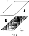
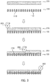
- Fig. 2 and Fig. 3 are a perspective view and a step mimetic diagram describing a method for manufacturing a negative electrode for a lithium secondary battery according to the present disclosure. Inserting a lithium thin film (200) to an opening (110) that a mesh-type anode current collector (100) forms may be accomplished by placing the lithium thin film (200) on the negative electrode current collector (100) and performing a rolling process.
- the present disclosure provides a method for manufacturing a negative electrode for a lithium secondary battery comprising i) preparing a mesh-type anode current collector (100); ii) placing a lithium thin film (200) on the negative electrode current collector (100); and iii) rolling the lithium thin film (200) and the negative electrode current collector (100) to insert the lithium thin film (200) to an opening (110) of the negative electrode current collector (100).
- the rolling may be carried out using common methods, and for example, the lithium thin film (200) may be inserted to an opening (110) of the negative electrode current collector (100) using a method of compressing with a pressure roller (300) provided in a roll press and the like, or compressing over the whole electrode surface using a plate-like press.
- a pressure of 10 kg/cm 2 to 100 ton/cm 2 may be applied, and heating to a temperature of 100°C to 200°C may be carried out.
- Heat treatment at the above-mentioned temperature includes either heating while carrying out a rolling process, or carrying out a rolling process while being heated before carrying out the rolling process.
- the degree of lithium thin film insertion may be controlled, and preferably, the lithium thin film may be rolled so as to satisfy the inserted portion thickness (d210) range described above.
- a positive electrode according to the present disclosure may be prepared into a positive electrode form by forming film on a positive electrode current collector using a composition comprising a positive electrode active material, a conductor and a binder.
- sulfides, selenides, halides and the like may also be used in addition to such oxides.
- the conductor is a component for further enhancing conductivity of a positive electrode active material, and non-limiting examples thereof may comprise graphite such as natural graphite or artificial graphite; carbon black such as carbon black, acetylene black, Ketjen black, channel black, furnace black, lamp black and thermal black; conductive polymers such as carbon fiber or metal fiber; metal powders such as fluorocarbon, aluminum and nickel powder; conductive whiskers such as zinc oxide and potassium titanate; conductive metal oxides such as titanium oxide; conductive materials such as polyphenylene derivatives, and the like.
- graphite such as natural graphite or artificial graphite
- carbon black such as carbon black, acetylene black, Ketjen black, channel black, furnace black, lamp black and thermal black
- conductive polymers such as carbon fiber or metal fiber
- metal powders such as fluorocarbon, aluminum and nickel powder
- conductive whiskers such as zinc oxide and potassium titanate
- conductive metal oxides such as titanium oxide
- conductive materials such as polyphen
- the binder has functions of keeping a positive electrode active material on a positive electrode current collector, and organically linking the positive electrode active materials, and examples thereof may comprise polyvinylidene fluoride (PVDF), polyvinyl alcohol (PVA), carboxymethylcellulose (CMC), starch, hydroxypropylcellulose, regenerated cellulose, polyvinyl pyrrolidone, tetrafluoroethylene, polyethylene, polypropylene, an ethylene-propylene-diene polymer (EPDM), a sulfonated-EPDM, styrene-butadiene rubber, fluoro rubber, various copolymers thereof, and the like.
- PVDF polyvinylidene fluoride
- PVA polyvinyl alcohol
- CMC carboxymethylcellulose
- EPDM ethylene-propylene-diene polymer
- sulfonated-EPDM styrene-butadiene rubber
- fluoro rubber various copolymers thereof, and the like.
- the positive electrode current collector is the same as described in the negative electrode current collector, and an aluminum thin plate may be generally used as the positive electrode current collector.
- the positive electrode composition may be coated on a positive electrode current collector using common methods known in the art, and various methods such as a dipping method, a spray method, a roll coat method, a gravure printing method, a bar coat method, a die coating method, a comma coating method or a mixed method thereof may be used.
- the positive electrode and the positive electrode composition gone through such a coating process are dried, and through the drying process, solvent or dispersion medium evaporation, compactness of the coating layer and adhesion between the coating layer and the current collector and the like are obtained.
- the drying is carried out using common methods, and is not particularly limited.
- a separator according to the present disclosure is not particularly limited in the material and, as a material physically separating a positive electrode and a negative electrode, and having electrolyte and ion penetrability, those commonly used as a separator in an electrochemical device may be used without particular limit. However, as a material that is porous, nonconductive and insulating, those having an excellent liquid electrolyte moisture-containing ability while having low resistance for ion migration of the liquid electrolyte is particularly preferred. For example, a polyolefin-based porous membrane or non-woven fabric may be used, however, the separator is not particularly limited thereto.
- membranes formed with a polymer using a polyolefin-based polymer such as polyethylene such as high density polyethylene, linear low density polyethylene, low density polyethylene and ultra-high molecular weight polyethylene, polypropylene, polybutylene and polypentene alone, or a polymer mixing these may be used.
- polyethylene such as high density polyethylene, linear low density polyethylene, low density polyethylene and ultra-high molecular weight polyethylene, polypropylene, polybutylene and polypentene alone, or a polymer mixing these may be used.
- non-woven fabric other than the polyolefin-based non-woven fabric described above, non-woven fabric formed with a polymer using, for example, polyphenylene oxide, polyimide, polyamide, polycarbonate, polyethylene terephthalate, polyethylene naphthalate, polybutylene terephthalate, polyphenylene sulfide, polyacetal, polyether sulfone, polyether ether ketone, polyester and the like alone, or a polymer mixing these may be used, and, as a fiber form forming a porous web, such non-woven fabric comprises a spunbond or meltblown form formed with long fibers.
- a polymer using, for example, polyphenylene oxide, polyimide, polyamide, polycarbonate, polyethylene terephthalate, polyethylene naphthalate, polybutylene terephthalate, polyphenylene sulfide, polyacetal, polyether sulfone, polyether ether ketone, polyester and the like alone, or a
- the thickness of the separator is not particularly limited, but is preferably in a range of 1 ⁇ m to 100 ⁇ m, and more preferably in a range of 5 ⁇ m to 50 ⁇ m. When the separator has a thickness of less than 1 ⁇ m, mechanical properties may not be maintained, and when the thickness is greater than 100 ⁇ m, the separator functions as a resistive layer declining battery performance.
- a pore size and porosity of the separator are not particularly limited, however, the pore size is preferably from 0.1 ⁇ m to 50 ⁇ m, and the porosity is preferably from 10% to 95%.
- the separator has a pore size of less than 0.1 ⁇ m or porosity of less than 10%, the separator functions as a resistive layer, and when the pore size is greater than 50 ⁇ m or the porosity is greater than 95%, mechanical properties may not be maintained.
- An electrolyte capable of being used in the present disclosure may be a non-aqueous liquid electrolyte or a solid electrolyte not reacting with lithium metal, but is preferably a non-aqueous electrolyte, and comprises an electrolyte salt and an organic solvent.
- the electrolyte salt included in the non-aqueous liquid electrolyte is a lithium salt.
- the lithium salt those commonly used in liquid electrolytes for a lithium secondary battery may be used without limit.
- an anion of the lithium salt may comprise any one selected from the group consisting of F - , Cl - , Br - , I - , NO 3 - , N(CN) 2 - , BF 4 - , ClO 4 -, PF 6 - , (CF 3 ) 2 PF 4 - , (CF 3 ) 3 PF 3 - , (CF 3 ) 4 PF2 - , (CF 3 ) 5 PF - , (CF 3 ) 6 P - , CF 3 SO 3 - , CF 3 CF 2 SO 3 - , (CF 3 SO 2 ) 2 N - , (FSO 2 ) 2 N - , CF 3 CF 2 (CF 3 ) 2 CO - , (CF 3 SO
- organic solvent included in the non-aqueous liquid electrolyte those commonly used in liquid electrolytes for a lithium secondary battery may be used without limit, and for example, ether, ester, amide, linear carbonate, cyclic carbonate and the like may be used either alone, or as a mixture of two or more types.
- a carbonate compound that is cyclic carbonate, linear carbonate or a mixture thereof may be typically included.
- cyclic carbonate compound may comprise any one selected from the group consisting of ethylene carbonate (EC), propylene carbonate (PC), 1,2-butylene carbonate, 2,3-butylene carbonate, 1,2-pentylene carbonate, 2,3-pentylene carbonate, vinylene carbonate, vinyl ethylene carbonate and halides thereof, or a mixture of two or more types thereof.
- halides thereof may comprise fluoroethylene carbonate (FEC) and the like, but are not limited thereto.
- linear carbonate compound may typically comprise any one selected from the group consisting of dimethyl carbonate (DMC), diethyl carbonate (DEC), dipropyl carbonate, ethylmethyl carbonate (EMC), methylpropyl carbonate and ethylpropyl carbonate, or a mixture of two or more types thereof, but are not limited thereto.
- DMC dimethyl carbonate
- DEC diethyl carbonate
- EMC ethylmethyl carbonate
- methylpropyl carbonate and ethylpropyl carbonate or a mixture of two or more types thereof, but are not limited thereto.
- ethylene carbonate and propylene carbonate that are cyclic carbonate are a high viscosity organic solvent and have a high dielectric constant, and therefore, may more favorably dissociate a lithium salt in an electrolyte, and when mixing and using linear carbonate having low viscosity and low dielectric constant such as dimethyl carbonate and diethyl carbonate in a proper ratio to such cyclic carbonate, a liquid electrolyte having higher electrical conductivity may be prepared.
- any one selected from the group consisting of dimethyl ether, diethyl ether, dipropyl ether, methylethyl ether, methylpropyl ether and ethylpropyl ether, or a mixture of two or more types thereof may be used, however, the ether is not limited thereto.
- any one selected from the group consisting of methyl acetate, ethyl acetate, propyl acetate, methyl propionate, ethyl propionate, propyl propionate, ⁇ -butyrolactone, ⁇ -valerolactone, ⁇ -caprolactone, ⁇ -valerolactone and ⁇ -caprolactone, or a mixture of two or more types thereof may be used, however, the ester is not limited thereto.
- the non-aqueous liquid electrolyte may be injected at a proper stage in an electrochemical device manufacturing process depending on a final product manufacturing process and required properties.
- the non-aqueous liquid electrolyte may be injected at a stage prior to assembling an electrochemical device or at a final stage of electrochemical device assembly.
- the lithium secondary battery according to the present disclosure may go through lamination (stack) and folding processes of a separator and an electrode in addition to winding, a general process.
- the battery case may be cylindrical, square, a pouch-type, a coin-type or the like.
- the lithium secondary battery according to the present disclosure stably exhibits excellent discharge capacity, output property and capacity retention rate, and therefore, is useful in the fields of portable devices such as mobile phones, notebook computers or digital cameras, electric vehicles such as hybrid electric vehicles (HEV), and the like.
- portable devices such as mobile phones, notebook computers or digital cameras, electric vehicles such as hybrid electric vehicles (HEV), and the like.
- HEV hybrid electric vehicles
- a battery module comprising the lithium secondary battery as a unit cell, and a battery pack comprising the same.
- the battery module or the battery pack may be used as a power supply of any one or more of medium to large sized devices among power tools; electric vehicles comprising electric vehicles (EV), hybrid electric vehicles and plug-in hybrid electric vehicles (PHEV); or systems for power storage.
- EV electric vehicles
- PHEV plug-in hybrid electric vehicles
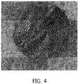
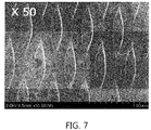
- Lithium foil having a thickness of 40 ⁇ m was placed on a copper mesh having a thickness of 25 ⁇ m (illustrated in Fig. 4 and Fig. 5 ) as a negative electrode current collector, a pressure was applied so that 50% of the thicknesses of the lithium foil was inserted, and the result was roll pressed to prepare a negative electrode (illustrated in Fig. 6 and Fig. 7 ).
- Cathode active material:conductor (carbon black) :binder (KF9700) were formed as a film in a composition of 95.5:2.0:2.5 on aluminum foil having a thickness of 12 ⁇ m as a positive electrode current collector to prepare a positive electrode.
- a separator coating SRS on both surfaces of a 8 ⁇ m polyethylene (PE) material each to a thickness of 2.5 ⁇ m was used as a separator to prepare a secondary battery.
- FEC/DEC was used as an electrolyte, and a liquid electrolyte containing 1 M of LiPF 6 and 0.5 wt% of additives was used to manufacture a lithium secondary battery.
- a lithium secondary battery was manufactured in the same manner as in Example 1 except that lithium foil having a thickness of 40 ⁇ m was placed on a copper mesh having a thickness of 25 ⁇ m (illustrated in Fig. 4 and Fig. 5 ) as the negative electrode current collector, and the thickness was controlled so that 40% of the thicknesses of the lithium foil was inserted.
- a lithium secondary battery was manufactured in the same manner as in Example 1 except that lithium foil having a thickness of 40 ⁇ m was placed on a copper mesh having a thickness of 25 ⁇ m (illustrated in Fig. 4 and Fig. 5 ) as the negative electrode current collector, and the thickness was controlled so that 30% of the thicknesses of the lithium foil was inserted.
- a lithium secondary battery was manufactured in the same manner as in Example 1 except that lithium foil having a thickness of 40 ⁇ m was placed on a copper mesh having a thickness of 25 ⁇ m (illustrated in Fig. 4 and Fig. 5 ) as the negative electrode current collector, and the thickness was controlled so that 20% of the thicknesses of the lithium foil was inserted.
- a lithium secondary battery was manufactured in the same manner as in Example 1 except that lithium foil having a thickness of 40 ⁇ m was placed on a copper mesh having a thickness of 25 ⁇ m (illustrated in Fig. 4 and Fig. 5 ) as the negative electrode current collector, and the thickness was controlled so that 10% of the thicknesses of the lithium foil was inserted.
- a lithium secondary battery was manufactured in the same manner as in Example 1 except that copper foil having a thickness of 20 ⁇ m was used as the negative electrode current collector, and the rolling process of the negative electrode was not carried out.
- Fig. 9 and table 2 shows data comparing rate performance of the lithium secondary batteries using the negative electrodes according to Examples 1 to 5 and Comparative Example 1 of the present disclosure.
- Example 2 Example 3
- Example 4 Example 5 Comparative Example 1 0.5 C/0.1 C 92.50 92.30 92.10 91.95 91.80 91.37 1.0 C/0.1 C 85.05 83.55 82.10 80.05 78.05 75.46 2.0 C/0.1 C 66.40 63.35 60.20 55.05 51.05 43.63 3.0 C/0.1 C 44.60 38.66 32.55 27.05 22.10 13.99
- the capacity retention rate was identified while fixing the charge rate and increasing the discharge C-rate.
- the results described in the table indicates capacity expression with respect to 0.1 C, and the 0.1 C capacity was identically expressed in the lithium secondary batteries of Example 1 and Comparative Example 1.
- the lithium secondary batteries of Examples 1 to 5 had a higher capacity retention rate compared to the lithium secondary battery of Comparative Example 1.
- the difference became larger as the C-rate increased.
- the lithium secondary battery of Example 1 exhibited a capacity retention rate of 66%, however, the lithium secondary battery of Comparative Example 1 had a capacity retention ratio of 44%, and the difference was approximately 22%.
- the lithium secondary batteries of Examples 2 to 5 also exhibited a superior capacity retention rate compared to Comparative Example 1.
- the negative electrode for a lithium secondary battery in which a part of a lithium thin film is inserted to a negative electrode current collector according to the present disclosure is capable of enhancing performance of the lithium secondary battery by increasing a surface area of contact between the lithium thin film and the negative electrode current collector, and is capable of enhancing safety of the lithium secondary battery by preventing lithium dendrite growth when driving the lithium secondary battery through uniformizing electron distribution inside the lithium electrode.
- volume expansion of a cell can be prevented as lithium dendrite formation is induced in empty space left while a part of the lithium thin film is inserted to an opening of the negative electrode current collector.
- an inserted portion of the lithium thin film and an opening of the negative electrode current collector are connected in a fitted manner and adhesion efficiency can be enhanced therefrom, and therefore, stripping of the negative electrode current collector and the lithium thin film can be prevented while charging and discharging the battery.
Landscapes
- Chemical & Material Sciences (AREA)
- Chemical Kinetics & Catalysis (AREA)
- Electrochemistry (AREA)
- General Chemical & Material Sciences (AREA)
- Engineering & Computer Science (AREA)
- Materials Engineering (AREA)
- Manufacturing & Machinery (AREA)
- Composite Materials (AREA)
- Cell Electrode Carriers And Collectors (AREA)
- Secondary Cells (AREA)
- Battery Electrode And Active Subsutance (AREA)
Abstract
Description
- The present disclosure relates to a negative electrode for a lithium secondary battery comprising a mesh-type current collector and a lithium thin film, and in particular, to a negative electrode in which a lithium thin film is inserted to an opening of a current collector and empty space is formed, a lithium secondary battery comprising the same, and a manufacturing method thereof.
- Interests in energy storage technologies have been increasingly higher recently. As applications are expanded to energy of mobile phones, camcorders and notebook PCs, and furthermore, to electric vehicles, efforts on the research and development of electrochemical devices have been more and more materialized.
- Electrochemical devices are fields receiving most attentions in such aspects and among these, development of secondary batteries capable of charge and discharge have been the focus of attention, and in developing such batteries, research and development on the design of new electrodes and batteries for enhancing capacity density and energy efficiency have been recently progressed.
- Among currently used secondary batteries, lithium secondary batteries developed in early 1990s have received attentions with advantages of having high operating voltage and significantly higher energy density compared to conventional batteries such as Ni-MH, Ni-Cd and sulfuric acid-lead batteries using an aqueous liquid electrolyte.
- A lithium secondary battery is generally formed by an electrode assembly comprising a positive electrode, a negative electrode and a separator provided between the positive electrode and the negative electrode being embedded in a battery case in a laminated or wound structure, and a non-aqueous liquid electrolyte being injected thereinto.
- As for a lithium electrode as the negative electrode, lithium foil attached on a planar current collector is used. In this case, lithium formation and elimination are irregular when charged and discharged producing lithium dendrite, and this leads to continuous capacity decline.
- In view of the above, studies introducing a polymer protective layer or inorganic solid protective layer to a lithium metal layer, increasing a salt concentration of a liquid electrolyte, or using proper additives have been progressed. However, effects of suppressing lithium dendrite resulted from such studies are insignificant. Accordingly, solving problems through modifying a form of a lithium metal anode itself or modifying a battery structure may be an effective option.
- Korean Patent No. 10-1621410 "Lithium Electrode and Lithium Secondary Battery comprising the Same"
- As described above, lithium dendrite of a lithium secondary battery is precipitated on a surface of a negative electrode current collector and volume expansion of a cell is sometimes caused therefrom. In view of the above, the inventors of the present disclosure have conducted studies from various angles and, as a result, have found out a method of solving such a problem caused by dendrite through modifying shape and structure of an electrode itself, and have completed the present disclosure.
- Accordingly, the present disclosure is directed to providing a lithium secondary battery solving a problem of volume expansion of a cell caused by lithium dendrite through modifying shape and structure of an electrode, and having enhanced cell performance.
- In view of the above, one embodiment of the present disclosure provides a negative electrode for a lithium secondary battery comprising a mesh-type anode current collector formed with a wire rod portion and an opening; and a lithium thin film formed with an inserted portion inserted to the opening of the negative electrode current collector and a non-inserted portion that is not inserted.
- Another embodiment of the present disclosure provides a method for manufacturing a negative electrode for a lithium secondary battery comprising preparing a mesh-type anode current collector; placing lithium metal foil on the negative electrode current collector; and rolling the lithium metal foil and the negative electrode current collector to insert the lithium metal to an opening of the negative electrode current collector.
- Still another embodiment of the present disclosure provides a lithium secondary battery comprising the negative electrode.
-
-
Fig. 1 is a cross-sectional view of a negative electrode for a lithium secondary battery comprising a lithium thin film inserted to an opening of a negative electrode current collector according to the present disclosure; -
Fig. 2 is a perspective view describing a method for manufacturing a negative electrode for a lithium secondary battery according to the present disclosure; -
Fig. 3 is a step mimetic diagram describing a method for manufacturing a negative electrode for a lithium secondary battery according to the present disclosure; -
Fig. 4 is an image of a mesh-type anode current collector used in Example 1 of the present disclosure; -
Fig. 5 is a SEM image of a mesh-type anode current collector used in Example 1 of the present disclosure; -
Fig. 6 is an image of a negative electrode for a lithium secondary battery according to Example 1 of the present disclosure; -
Fig. 7 is a SEM image of a negative electrode for a lithium secondary battery according to Example 1 of the present disclosure; -
Fig. 8 shows initial capacity and efficiency data of lithium secondary batteries using anodes according to Example 1 and Comparative Example 1 of the present disclosure; and -
Fig. 9 shows data comparing rate performance of lithium secondary batteries using anodes according to Example 1 and Comparative Example 1 of the present disclosure.- 100. Anode Current Collector
- 110. Opening
- 120. Wire Rod Portion
- 200. Lithium Thin Film
- 210. Inserted portion
- 220. Non-Inserted portion
- 300. Pressure Roller
- Hereinafter, embodiments of the present disclosure will be described in detail with reference to the accompanying drawings so that those skilled in the art may readily implement the present disclosure. However, the present disclosure may be implemented in various different forms, and is not limited to the embodiments described herein.
- In the drawings, parts not relevant to the descriptions are not included in order to clearly describe the present disclosure, and like reference numerals are used for like elements throughout the specification. In addition, sizes and relative sizes of constituents shown in the drawings are unrelated to actual scales, and may be reduced or exaggerated for clarity of the descriptions.
-
Fig. 1 is a cross-sectional view of a negative electrode for a lithium secondary battery comprising a lithium thin film inserted to an opening of a negative electrode current collector according to the present disclosure. When referring toFig. 1 , the present disclosure provides a negative electrode for a lithium secondary battery comprising a mesh-type anode current collector (100) formed with a wire rod portion (120) and an opening (110); and a lithium thin film (200) formed with an inserted portion (210) inserted to the opening (110) of the negative electrode current collector (100) and a non-inserted portion (220) that is not inserted. - The negative electrode for a lithium secondary battery according to the present disclosure has a structure in which the lithium thin film (200) is inserted while one surface thereof adjoins on an upper surface of the mesh-type anode current collector (100), and this leaves empty space in the opening (110) as a part of the lithium thin film (200) is inserted to the opening (110) of the negative electrode current collector (100). This space induces lithium dendrite formation preventing volume expansion of a cell.
- In the present disclosure, the electrode material formed on the negative electrode current collector (100) is preferably a lithium thin film (200). Lithium thin film (200) has malleability and ductility, unique properties of a metal film, and changes its form while spreading thinly when applying a pressure, and therefore, may be inserted to the mesh-type anode current collector opening (110) with only a rolling process.
- However, among materials used as a negative electrode in a lithium secondary battery, a negative electrode active material that comprises lithium in a form that is not a thin film form is normally prepared into a slurry mixture and a coating process coating the slurry mixture on a negative electrode current collector is carried out, and unlike lithium in a thin film form, such a slurry mixture is difficult to be inserted to an opening of a mesh-type anode current collector through a coating film-forming process or a rolling process thereafter, and cracks may also occur due to a pressure applied in the rolling process. Even when the slurry mixture inserted to an opening of a negative electrode current collector by controlling viscosity of the slurry mixture, there is a problem in that controlling the viscosity enough to secure empty space to a target level aimed in the present disclosure is very difficult.
- Accordingly, a lithium thin film (200) is preferably used as a negative electrode material in the present disclosure, and an inserted portion thickness (d210) of such a lithium thin film (200) is controlled to be 20% to 60% of the thickness of the whole lithium thin film. In other words, space filled with the inserted portion (210) of the lithium thin film is from 20% to 60% of the thickness of the whole lithium thin film, and accordingly, empty space is preserved in the opening (110) space. Dendrite is formed in such remaining space of the opening (110) while gone through charge and discharge, and as a result, volume expansion of a cell may be prevented.
- Herein, as for a non-inserted portion thickness (d220) of the lithium thin film (200), it is preferred that 40% to 80% of the total lithium thin film thickness (d200) is left and only the rest is inserted. When the lithium thin film (200) is not completely inserted and a part thereof is left, space remains inside the negative electrode current collector (100), and effects described above are secured. In addition, as both surfaces of the lithium thin film (200) are exposed to a liquid electrolyte, a stable SEI membrane is formed on the both surfaces preventing the Li metal surface from being exposed, and as a result, electrolyte decomposition caused from charge and discharge may be prevented.
- As for a thickness (d200) of the lithium thin film, those having a thickness of 10 µm to 800 µm are selected, and selecting those having a larger thickness than the negative electrode current collector is preferred. The reason is to secure a sufficient non-inserted portion (220) thickness even after the lithium thin film (200) is inserted to the opening (110) of the negative electrode current collector.
- In addition, as the negative electrode current collector (100), those having a thickness range of 3 µm to 500 µm are used. When the negative electrode current collector has a thickness of less than 3 µm, a current collecting effect decreases, and an opening (110) having a sufficient size to collect lithium dendrite is not secured. Meanwhile, the thickness being greater than 500 µm has a problem of reducing processibility when assembling a cell through folding.
- An effect of suppressing lithium dendrite growth is excellent as the size of one opening (110) of the negative electrode current collector (100) is smaller and the percentage of the opening (110) is higher. More specifically, as the wire rod portion (120) of the negative electrode current collector (100), those having a line width of 50 µm to 500 µm and line spacing of 100 µm to 1 mm may be selected, and the size of one opening (110) that such a wire rod portion (120) forms is preferably from 10 µm to 300 µm in securing the above-mentioned effects.
- In addition, as for the percentage of the opening (110) in the negative electrode current collector (100), an aperture ratio, the percentage of the area occupied by the opening (110) region, is preferably from 20% to 80% based on the
total area 100% of the negative electrode current collector (100). When the aperture ratio is less than 20%, the effect of inducing precipitation and elimination reactions of lithium dendrite, a goal of the present disclosure, may not be secured, and when the aperture ratio is greater than 80%, the area of contact between the negative electrode current collector and the lithium metal layer relatively decreases, which is not proper in performing a role as a negative electrode current collector, and as a result, battery performance declines. - The shape of the opening (110) formed by such a wire rod portion (120) of the negative electrode current collector (100) is not limited, and examples thereof may comprise a circular, oval or polygonal shape.
- The negative electrode current collector (100) is not particularly limited as long as it has high conductivity without inducing chemical changes in a battery, and may be selected from the group consisting of copper, aluminum, stainless steel, zinc, titanium, silver, palladium, nickel, iron, chromium, alloys thereof and combinations thereof. The stainless steel may have its surface treated with carbon, nickel, titanium or silver, and aluminum-cadmium alloys may be used as the alloy, and in addition thereto, baked carbon, nonconductive polymers of which surface is treated with a conductor, conductive polymers or the like may also be used. As the negative electrode current collector, a copper thin plate is generally used.
- The negative electrode for a lithium secondary battery in which a part of a lithium thin film is inserted to a negative electrode current collector according to the present disclosure is capable of enhancing safety of the lithium secondary battery by increasing a surface area of contact between the lithium thin film and the negative electrode current collector, uniformizing electron distribution inside the lithium electrode, and inducing lithium dendrite precipitation in empty space inside the current collector.
- Furthermore, the present disclosure provides a negative electrode for a lithium secondary battery comprising a mesh-type anode current collector formed with a wire rod portion and an opening; a lithium thin film formed with an inserted portion inserted to the opening of the negative electrode current collector and a non-inserted portion that is not inserted; and a protection structure formed on a surface opposite to the lithium thin film that the negative electrode current collector faces, wherein the protection structure is formed with an organic polymer portion and an inorganic material portion, and the organic polymer portion is formed on a surface opposite to the lithium thin film that the wire rod portion adjoins and the inorganic material portion is formed on a surface opposite to the lithium thin film corresponding to the opening.
- The protection structure according to the present disclosure may provide an ion path between a negative electrode and an electrolyte. Such a protection structure has a form of an inorganic material filling space between frames that the organic polymer portion forms, and although an inorganic material cell or layer formed with specific ceramic/glassy may comprise pin-holes, cracks and/or crystal grain-based defects that may spread through the whole cell or layer, the presence of a number of ion paths may minimize the influence of defects in any one ion path. Accordingly, when defects are present in the protection structure, this is typically much less fatal compared to when present inside a protection structure comprising one or more continuous ceramic layers. For example, defects may be isolated (for example, at least partly surrounded by polymer materials), and therefore, the defects spreading to other ion paths (for example, inorganic material-filled cavity) may be reduced or avoided.
- The organic polymer portion provides advantageous mechanical properties such as flexibility and strength of the protection structure. Placing a cell filled with an inorganic material inside a polymer frame may reduce weakness of the inorganic material-filled cavity for crack mechanism. The material is not limited, and for example, may be selected from among polyvinyl alcohol, polyisobutylene, epoxy, polyethylene, polypropylene, polytetrafluoroethylene and combinations thereof as a nonionic conductive polymer.
- The inorganic material portion may be a ceramic-based or glassy-based material as a material ionic communicating with the lithium thin film, and for example, may be selected from among Li2O, Li3N, Al2O3, ZrO2, SiO2, CeO2, Al2TiO5, oxy-sulfide glass and combinations thereof.
- The protection structure may be prepared by, for example, preparing a frame with an organic polymer portion following a wire rod portion that forms a mesh-form of a negative electrode current collector, and then filling the space therebetween with an inorganic material, and as the method, methods such as electron beam deposition, sputtering and thermal deposition may be used.
-
Fig. 2 andFig. 3 are a perspective view and a step mimetic diagram describing a method for manufacturing a negative electrode for a lithium secondary battery according to the present disclosure. Inserting a lithium thin film (200) to an opening (110) that a mesh-type anode current collector (100) forms may be accomplished by placing the lithium thin film (200) on the negative electrode current collector (100) and performing a rolling process. More specifically, the present disclosure provides a method for manufacturing a negative electrode for a lithium secondary battery comprising i) preparing a mesh-type anode current collector (100); ii) placing a lithium thin film (200) on the negative electrode current collector (100); and iii) rolling the lithium thin film (200) and the negative electrode current collector (100) to insert the lithium thin film (200) to an opening (110) of the negative electrode current collector (100). - The rolling may be carried out using common methods, and for example, the lithium thin film (200) may be inserted to an opening (110) of the negative electrode current collector (100) using a method of compressing with a pressure roller (300) provided in a roll press and the like, or compressing over the whole electrode surface using a plate-like press.
- Particularly, in such a rolling process, a pressure of 10 kg/cm2 to 100 ton/cm2 may be applied, and heating to a temperature of 100°C to 200°C may be carried out. Heat treatment at the above-mentioned temperature includes either heating while carrying out a rolling process, or carrying out a rolling process while being heated before carrying out the rolling process. By controlling temperature and pressure conditions as above, the degree of lithium thin film insertion may be controlled, and preferably, the lithium thin film may be rolled so as to satisfy the inserted portion thickness (d210) range described above.
- As for a lithium secondary battery according to the present disclosure, constitutions other than the structure and the properties of the negative electrode described above may be prepared through known technologies implemented by those skilled in the art, and will be specifically described below.
- A positive electrode according to the present disclosure may be prepared into a positive electrode form by forming film on a positive electrode current collector using a composition comprising a positive electrode active material, a conductor and a binder.
- As the positive electrode active material, any one selected from the group consisting of LiCoO2, LiNiO2, LiMnO2, LiMn2O4, Li(NiaCobMnc)O2 (0<a<1, 0<b<1, 0<c<1, a+b+c=1), LiNi1-yCoyO2, LiCo1-yMnyO2, LiCo1-yMnyO2, (0≤y<1), Li(NiaCobMnc)O4 (0<a<2, 0<b<2, 0<c<2, a+b+c=2), LiMn2-zNiZO4, LiMn2-zCozO4 (0<z<2), LiCoPO4 and LiFePO4, or a mixture of two or more types thereof may be used. In addition, sulfides, selenides, halides and the like may also be used in addition to such oxides. In more preferred examples, the positive electrode active material may be LiCoO2 suitable for a high power battery.
- The conductor is a component for further enhancing conductivity of a positive electrode active material, and non-limiting examples thereof may comprise graphite such as natural graphite or artificial graphite; carbon black such as carbon black, acetylene black, Ketjen black, channel black, furnace black, lamp black and thermal black; conductive polymers such as carbon fiber or metal fiber; metal powders such as fluorocarbon, aluminum and nickel powder; conductive whiskers such as zinc oxide and potassium titanate; conductive metal oxides such as titanium oxide; conductive materials such as polyphenylene derivatives, and the like.
- The binder has functions of keeping a positive electrode active material on a positive electrode current collector, and organically linking the positive electrode active materials, and examples thereof may comprise polyvinylidene fluoride (PVDF), polyvinyl alcohol (PVA), carboxymethylcellulose (CMC), starch, hydroxypropylcellulose, regenerated cellulose, polyvinyl pyrrolidone, tetrafluoroethylene, polyethylene, polypropylene, an ethylene-propylene-diene polymer (EPDM), a sulfonated-EPDM, styrene-butadiene rubber, fluoro rubber, various copolymers thereof, and the like.
- The positive electrode current collector is the same as described in the negative electrode current collector, and an aluminum thin plate may be generally used as the positive electrode current collector.
- The positive electrode composition may be coated on a positive electrode current collector using common methods known in the art, and various methods such as a dipping method, a spray method, a roll coat method, a gravure printing method, a bar coat method, a die coating method, a comma coating method or a mixed method thereof may be used.
- The positive electrode and the positive electrode composition gone through such a coating process are dried, and through the drying process, solvent or dispersion medium evaporation, compactness of the coating layer and adhesion between the coating layer and the current collector and the like are obtained. Herein, the drying is carried out using common methods, and is not particularly limited.
- A separator according to the present disclosure is not particularly limited in the material and, as a material physically separating a positive electrode and a negative electrode, and having electrolyte and ion penetrability, those commonly used as a separator in an electrochemical device may be used without particular limit. However, as a material that is porous, nonconductive and insulating, those having an excellent liquid electrolyte moisture-containing ability while having low resistance for ion migration of the liquid electrolyte is particularly preferred. For example, a polyolefin-based porous membrane or non-woven fabric may be used, however, the separator is not particularly limited thereto.
- As examples of the polyolefin-based porous membrane, membranes formed with a polymer using a polyolefin-based polymer such as polyethylene such as high density polyethylene, linear low density polyethylene, low density polyethylene and ultra-high molecular weight polyethylene, polypropylene, polybutylene and polypentene alone, or a polymer mixing these may be used.
- As the non-woven fabric other than the polyolefin-based non-woven fabric described above, non-woven fabric formed with a polymer using, for example, polyphenylene oxide, polyimide, polyamide, polycarbonate, polyethylene terephthalate, polyethylene naphthalate, polybutylene terephthalate, polyphenylene sulfide, polyacetal, polyether sulfone, polyether ether ketone, polyester and the like alone, or a polymer mixing these may be used, and, as a fiber form forming a porous web, such non-woven fabric comprises a spunbond or meltblown form formed with long fibers.
- The thickness of the separator is not particularly limited, but is preferably in a range of 1 µm to 100 µm, and more preferably in a range of 5 µm to 50 µm. When the separator has a thickness of less than 1 µm, mechanical properties may not be maintained, and when the thickness is greater than 100 µm, the separator functions as a resistive layer declining battery performance.
- A pore size and porosity of the separator are not particularly limited, however, the pore size is preferably from 0.1 µm to 50 µm, and the porosity is preferably from 10% to 95%. When the separator has a pore size of less than 0.1 µm or porosity of less than 10%, the separator functions as a resistive layer, and when the pore size is greater than 50 µm or the porosity is greater than 95%, mechanical properties may not be maintained.
- An electrolyte capable of being used in the present disclosure may be a non-aqueous liquid electrolyte or a solid electrolyte not reacting with lithium metal, but is preferably a non-aqueous electrolyte, and comprises an electrolyte salt and an organic solvent.
- The electrolyte salt included in the non-aqueous liquid electrolyte is a lithium salt. As the lithium salt, those commonly used in liquid electrolytes for a lithium secondary battery may be used without limit. For example, an anion of the lithium salt may comprise any one selected from the group consisting of F-, Cl-, Br-, I-, NO3 -, N(CN)2 -, BF4 -, ClO4-, PF6 -, (CF3)2PF4 -, (CF3)3PF3 -, (CF3)4PF2-, (CF3)5PF-, (CF3)6P-, CF3SO3 -, CF3CF2SO3 -, (CF3SO2)2N-, (FSO2)2N-, CF3CF2(CF3)2CO-, (CF3SO2)2CH-, (SF5)3C-, (CF3SO2)3C-, CF3 (CF2)7SO3 -, CF3CO2 -, CH3CO2 -, SCN- and (CF3CF2SO2)2N-, or two or more types thereof.
- As the organic solvent included in the non-aqueous liquid electrolyte, those commonly used in liquid electrolytes for a lithium secondary battery may be used without limit, and for example, ether, ester, amide, linear carbonate, cyclic carbonate and the like may be used either alone, or as a mixture of two or more types. Among these, a carbonate compound that is cyclic carbonate, linear carbonate or a mixture thereof may be typically included.
- Specific examples of the cyclic carbonate compound may comprise any one selected from the group consisting of ethylene carbonate (EC), propylene carbonate (PC), 1,2-butylene carbonate, 2,3-butylene carbonate, 1,2-pentylene carbonate, 2,3-pentylene carbonate, vinylene carbonate, vinyl ethylene carbonate and halides thereof, or a mixture of two or more types thereof. Examples of the halides thereof may comprise fluoroethylene carbonate (FEC) and the like, but are not limited thereto.
- Specific examples of the linear carbonate compound may typically comprise any one selected from the group consisting of dimethyl carbonate (DMC), diethyl carbonate (DEC), dipropyl carbonate, ethylmethyl carbonate (EMC), methylpropyl carbonate and ethylpropyl carbonate, or a mixture of two or more types thereof, but are not limited thereto.
- Particularly, among the carbonate-based organic solvents, ethylene carbonate and propylene carbonate that are cyclic carbonate are a high viscosity organic solvent and have a high dielectric constant, and therefore, may more favorably dissociate a lithium salt in an electrolyte, and when mixing and using linear carbonate having low viscosity and low dielectric constant such as dimethyl carbonate and diethyl carbonate in a proper ratio to such cyclic carbonate, a liquid electrolyte having higher electrical conductivity may be prepared.
- In addition, as the ether among the organic solvents, any one selected from the group consisting of dimethyl ether, diethyl ether, dipropyl ether, methylethyl ether, methylpropyl ether and ethylpropyl ether, or a mixture of two or more types thereof may be used, however, the ether is not limited thereto.
- As the ester among the organic solvents, any one selected from the group consisting of methyl acetate, ethyl acetate, propyl acetate, methyl propionate, ethyl propionate, propyl propionate, γ-butyrolactone, γ-valerolactone, γ-caprolactone, σ-valerolactone and ε-caprolactone, or a mixture of two or more types thereof may be used, however, the ester is not limited thereto.
- The non-aqueous liquid electrolyte may be injected at a proper stage in an electrochemical device manufacturing process depending on a final product manufacturing process and required properties. In other words, the non-aqueous liquid electrolyte may be injected at a stage prior to assembling an electrochemical device or at a final stage of electrochemical device assembly.
- The lithium secondary battery according to the present disclosure may go through lamination (stack) and folding processes of a separator and an electrode in addition to winding, a general process. In addition, the battery case may be cylindrical, square, a pouch-type, a coin-type or the like.
- As above, the lithium secondary battery according to the present disclosure stably exhibits excellent discharge capacity, output property and capacity retention rate, and therefore, is useful in the fields of portable devices such as mobile phones, notebook computers or digital cameras, electric vehicles such as hybrid electric vehicles (HEV), and the like.
- Accordingly, another embodiment of the present disclosure provides a battery module comprising the lithium secondary battery as a unit cell, and a battery pack comprising the same. The battery module or the battery pack may be used as a power supply of any one or more of medium to large sized devices among power tools; electric vehicles comprising electric vehicles (EV), hybrid electric vehicles and plug-in hybrid electric vehicles (PHEV); or systems for power storage.
- Hereinafter, the present disclosure will be described in detail with reference to examples. However, examples according to the present disclosure may be modified to various different forms, and the scope of the present disclosure is not to be construed as being limited to the examples described below. The examples of the present disclosure are provided to those having average knowledge in the art in order to more completely describe the present disclosure.
- Lithium foil having a thickness of 40 µm was placed on a copper mesh having a thickness of 25 µm (illustrated in
Fig. 4 andFig. 5 ) as a negative electrode current collector, a pressure was applied so that 50% of the thicknesses of the lithium foil was inserted, and the result was roll pressed to prepare a negative electrode (illustrated inFig. 6 andFig. 7 ). - Cathode active material:conductor (carbon black) :binder (KF9700) were formed as a film in a composition of 95.5:2.0:2.5 on aluminum foil having a thickness of 12 µm as a positive electrode current collector to prepare a positive electrode.
- A separator coating SRS on both surfaces of a 8 µm polyethylene (PE) material each to a thickness of 2.5 µm was used as a separator to prepare a secondary battery. FEC/DEC was used as an electrolyte, and a liquid electrolyte containing 1 M of LiPF6 and 0.5 wt% of additives was used to manufacture a lithium secondary battery.
- A lithium secondary battery was manufactured in the same manner as in Example 1 except that lithium foil having a thickness of 40 µm was placed on a copper mesh having a thickness of 25 µm (illustrated in
Fig. 4 andFig. 5 ) as the negative electrode current collector, and the thickness was controlled so that 40% of the thicknesses of the lithium foil was inserted. - A lithium secondary battery was manufactured in the same manner as in Example 1 except that lithium foil having a thickness of 40 µm was placed on a copper mesh having a thickness of 25 µm (illustrated in
Fig. 4 andFig. 5 ) as the negative electrode current collector, and the thickness was controlled so that 30% of the thicknesses of the lithium foil was inserted. - A lithium secondary battery was manufactured in the same manner as in Example 1 except that lithium foil having a thickness of 40 µm was placed on a copper mesh having a thickness of 25 µm (illustrated in
Fig. 4 andFig. 5 ) as the negative electrode current collector, and the thickness was controlled so that 20% of the thicknesses of the lithium foil was inserted. - A lithium secondary battery was manufactured in the same manner as in Example 1 except that lithium foil having a thickness of 40 µm was placed on a copper mesh having a thickness of 25 µm (illustrated in
Fig. 4 andFig. 5 ) as the negative electrode current collector, and the thickness was controlled so that 10% of the thicknesses of the lithium foil was inserted. - A lithium secondary battery was manufactured in the same manner as in Example 1 except that copper foil having a thickness of 20 µm was used as the negative electrode current collector, and the rolling process of the negative electrode was not carried out.
- For the lithium secondary batteries of Examples 1 to 5 and Comparative Example 1, a charge and discharge test was carried out under a condition of 0.1 C charge/0.1 C discharge, and the results are shown in
Fig. 8 and summarized in the following Table 1.[Table 1] Charge Capacity (mAh/g) Discharge Capacity (mAh/g) Efficiency (%) Example 1 225 210 93.22 Example 2 224 209 93.30 Example 3 225 209 92.88 Example 4 226 210 92.92 Example 5 224 209 93.30 Comparative Example 1 226 210 93.14 - As shown in Table 1, initial charge and discharge capacity and efficiency of the lithium secondary batteries of Examples 1 to 5 and Comparative Example 1 were similar.
-
Fig. 9 and table 2 shows data comparing rate performance of the lithium secondary batteries using the negative electrodes according to Examples 1 to 5 and Comparative Example 1 of the present disclosure.[Table 2] Capacity Retention (%, Compared to 0.1 C) Discharge C-rate Example 1 Example 2 Example 3 Example 4 Example 5 Comparative Example 1 0.5 C/0.1 C 92.50 92.30 92.10 91.95 91.80 91.37 1.0 C/0.1 C 85.05 83.55 82.10 80.05 78.05 75.46 2.0 C/0.1 C 66.40 63.35 60.20 55.05 51.05 43.63 3.0 C/0.1 C 44.60 38.66 32.55 27.05 22.10 13.99 - The capacity retention rate was identified while fixing the charge rate and increasing the discharge C-rate. The results described in the table indicates capacity expression with respect to 0.1 C, and the 0.1 C capacity was identically expressed in the lithium secondary batteries of Example 1 and Comparative Example 1. However, when increasing the discharge rate, the lithium secondary batteries of Examples 1 to 5 had a higher capacity retention rate compared to the lithium secondary battery of Comparative Example 1. The difference became larger as the C-rate increased. When discharging with 2.0 C, the lithium secondary battery of Example 1 exhibited a capacity retention rate of 66%, however, the lithium secondary battery of Comparative Example 1 had a capacity retention ratio of 44%, and the difference was approximately 22%. The lithium secondary batteries of Examples 2 to 5 also exhibited a superior capacity retention rate compared to Comparative Example 1.
- In other words, when using mesh Cu, the contact area between Li metal and Cu increases, and resistance inside a cell is reduced as electrical conductivity becomes superior. Besides, cell performance is enhanced while dendrite formation is induced inside empty space of an opening described above. When using general Cu foil, interfacial resistance between a separator and Li metal increases while dendrite is formed on the Li metal surface touching the separator when charged and discharged, however, when using Mesh Cu, a phenomenon of increasing interfacial resistance between Li metal and a separator may be prevented even after charge and discharge as dendrite formation is induced inside empty space of an opening.
- The negative electrode for a lithium secondary battery in which a part of a lithium thin film is inserted to a negative electrode current collector according to the present disclosure is capable of enhancing performance of the lithium secondary battery by increasing a surface area of contact between the lithium thin film and the negative electrode current collector, and is capable of enhancing safety of the lithium secondary battery by preventing lithium dendrite growth when driving the lithium secondary battery through uniformizing electron distribution inside the lithium electrode.
- In addition, volume expansion of a cell can be prevented as lithium dendrite formation is induced in empty space left while a part of the lithium thin film is inserted to an opening of the negative electrode current collector.
- Furthermore, when compared to existing simple joint structures, an inserted portion of the lithium thin film and an opening of the negative electrode current collector are connected in a fitted manner and adhesion efficiency can be enhanced therefrom, and therefore, stripping of the negative electrode current collector and the lithium thin film can be prevented while charging and discharging the battery.
Claims (15)
- A negative electrode for a lithium secondary battery comprising:a mesh-type anode current collector formed with a wire rod portion and an opening; anda lithium thin film formed with an inserted portion inserted to the opening of the negative electrode current collector and a non-inserted portion that is not inserted.
- The negative electrode for a lithium secondary battery of Claim 1, wherein a thickness of the inserted portion of the lithium thin film is 20% to 60% of a thickness of the whole lithium thin film.
- The negative electrode for a lithium secondary battery of Claim 1, wherein a thickness of the non-inserted portion of the lithium thin film is 40% to 80% of a thickness of the whole lithium thin film.
- The negative electrode for a lithium secondary battery of Claim 1, wherein a thickness of the lithium thin film is from 10 µm to 800 µm.
- The negative electrode for a lithium secondary battery of Claim 1, wherein the wire rod portion of the negative electrode current collector has a line width of 50 µm to 500 µm and line spacing of 100 µm to 1 mm.
- The negative electrode for a lithium secondary battery of Claim 1, wherein a shape of the opening of the negative electrode current collector is circular, oval or polygonal.
- The negative electrode for a lithium secondary battery of Claim 1, wherein an aperture ratio of the negative electrode current collector is from 20% to 80%.
- The negative electrode for a lithium secondary battery of Claim 1, wherein a thickness of the negative electrode current collector is from 3 µm to 500 µm.
- The negative electrode for a lithium secondary battery of Claim 1, wherein the negative electrode current collector is one or more types selected from the group consisting of copper, aluminum, stainless steel, zinc, titanium, silver, palladium, nickel, iron, chromium, alloys thereof and combinations thereof.
- A negative electrode for a lithium secondary battery comprising:a mesh-type anode current collector formed with a wire rod portion and an opening;a lithium thin film formed with an inserted portion inserted to the opening of the negative electrode current collector and a non-inserted portion that is not inserted; anda protection structure formed on a surface opposite to the lithium thin film that the negative electrode current collector faces,wherein the protection structure is formed with an organic polymer portion and an inorganic material portion, and the organic polymer portion is formed on a surface opposite to the lithium thin film that the wire rod portion adjoins and the inorganic material portion is formed on a surface opposite to the lithium thin film corresponding to the opening.
- The negative electrode for a lithium secondary battery of Claim 10, wherein the organic polymer portion is selected from among polyvinyl alcohol, polyisobutylene, epoxy, polyethylene, polypropylene, polytetrafluoroethylene and combinations thereof.
- The negative electrode for a lithium secondary battery of Claim 10, wherein the inorganic material portion is selected from among Li2O, Li3N, Al2O3, ZrO2, SiO2, CeO2, Al2TiO5, oxy-sulfide glass and combinations thereof.
- A method for manufacturing a negative electrode for a lithium secondary battery comprising:i) preparing a mesh-type anode current collector;ii) placing lithium thin film on the negative electrode current collector; andiii) rolling the lithium thin film and the negative electrode current collector to insert the lithium thin film to an opening of the negative electrode current collector.
- The method for manufacturing the negative electrode for a lithium secondary battery of Claim 13, wherein the rolling in iii) is applying a pressure of 10 kg/cm2 to 100 ton/cm2 .
- The method for manufacturing the negative electrode for a lithium secondary battery of Claim 13, wherein the rolling in iii) is heating to a temperature of 100°C to 200 °C.
Applications Claiming Priority (2)
| Application Number | Priority Date | Filing Date | Title |
|---|---|---|---|
| KR20160094371 | 2016-07-25 | ||
| KR1020170090152A KR102148506B1 (en) | 2016-07-25 | 2017-07-17 | Anode Comprising Mesh Type Current Collector, Lithium Secondary Battery Comprising the Same and Manufacturing Method thereof |
Publications (2)
| Publication Number | Publication Date |
|---|---|
| EP3276709A1 true EP3276709A1 (en) | 2018-01-31 |
| EP3276709B1 EP3276709B1 (en) | 2023-04-12 |
Family
ID=59399314
Family Applications (1)
| Application Number | Title | Priority Date | Filing Date |
|---|---|---|---|
| EP17182964.1A Active EP3276709B1 (en) | 2016-07-25 | 2017-07-25 | Negative electrode comprising mesh-type current collector, lithium secondary battery comprising the same, and manufacturing method thereof |
Country Status (7)
| Country | Link |
|---|---|
| US (1) | US10686193B2 (en) |
| EP (1) | EP3276709B1 (en) |
| JP (1) | JP6628289B2 (en) |
| CN (1) | CN107658472B (en) |
| ES (1) | ES2944948T3 (en) |
| HU (1) | HUE061993T2 (en) |
| PL (1) | PL3276709T3 (en) |
Families Citing this family (15)
| Publication number | Priority date | Publication date | Assignee | Title |
|---|---|---|---|---|
| CN111640915B (en) * | 2019-03-01 | 2024-12-31 | 麻省固能控股有限公司 | Negative electrode, secondary battery including the same, and method for manufacturing the negative electrode |
| US11444277B2 (en) | 2019-03-01 | 2022-09-13 | Ses Holdings Pte. Ltd. | Anodes, secondary batteries including the same, and methods of making anodes |
| CA3137941A1 (en) * | 2019-04-26 | 2020-10-29 | Ppg Industries Ohio, Inc. | Electrodes having conformal coatings deposited onto porous electrical current collectors |
| ES2951119T3 (en) * | 2019-04-30 | 2023-10-18 | Innolith Tech Ag | Rechargeable battery cell |
| WO2021006327A1 (en) * | 2019-07-10 | 2021-01-14 | 積水化学工業株式会社 | Metal sheet having carbon material, electrode for electricity storage device, and electricity storage device |
| CN112447942B (en) * | 2019-08-27 | 2022-04-05 | 北京航空航天大学 | A kind of square lithium metal battery and preparation method thereof |
| AU2021273919A1 (en) | 2020-05-22 | 2022-10-06 | Duracell U.S. Operations, Inc. | Seal assembly for a battery cell |
| US11688843B2 (en) | 2020-08-31 | 2023-06-27 | GM Global Technology Operations LLC | Calendered electrode and method of making same |
| TWI803088B (en) | 2020-12-28 | 2023-05-21 | 財團法人工業技術研究院 | Negative electrode and lithium ion battery employing the same |
| EP4089781A4 (en) * | 2021-03-31 | 2023-05-31 | Ningde Amperex Technology Ltd. | ELECTROCHEMICAL DEVICE AND ELECTRONIC DEVICE |
| US11735744B2 (en) * | 2021-04-28 | 2023-08-22 | GM Global Technology Operations LLC | Method and apparatus for fabricating an electrode for a battery |
| US20220352496A1 (en) * | 2021-04-28 | 2022-11-03 | GM Global Technology Operations LLC | Method and apparatus for fabricating an electrode for a battery |
| CN114914454B (en) * | 2022-07-01 | 2023-05-26 | 北京理工大学重庆创新中心 | High-entropy alloy current collector and preparation method and application thereof |
| CN115832324B (en) * | 2022-11-14 | 2025-03-04 | 宁德时代新能源科技股份有限公司 | Current collector, battery pole piece, secondary battery and electrical device |
| US20250158013A1 (en) * | 2023-11-13 | 2025-05-15 | GM Global Technology Operations LLC | One-sided rolling insertion of thick lithium into a 3d current collector |
Citations (5)
| Publication number | Priority date | Publication date | Assignee | Title |
|---|---|---|---|---|
| JPH0729596A (en) * | 1993-07-14 | 1995-01-31 | Nippon Telegr & Teleph Corp <Ntt> | Lithium secondary battery |
| WO2011152244A1 (en) * | 2010-05-31 | 2011-12-08 | 住友電気工業株式会社 | Alloy negative electrode for lithium battery and process for production thereof, and lithium battery |
| EP1734547B1 (en) * | 2004-03-31 | 2012-09-26 | Fuji Jukogyo Kabushiki Kaisha | Organic electrolyte capacitor using mesoporous carbon material as negative electrode |
| US20140272558A1 (en) * | 2013-03-14 | 2014-09-18 | GM Global Technology Operations LLC | Electrode for a lithium-based secondary electrochemical device and method of forming same |
| US20150295246A1 (en) * | 2013-09-11 | 2015-10-15 | Lg Chem, Ltd. | Lithium electrode and lithium secondary battery comprising the same |
Family Cites Families (41)
| Publication number | Priority date | Publication date | Assignee | Title |
|---|---|---|---|---|
| JPS6126260A (en) | 1984-07-16 | 1986-02-05 | Meidensha Electric Mfg Co Ltd | Gto thyristor |
| JPS6126260U (en) * | 1984-07-20 | 1986-02-17 | 三洋電機株式会社 | non-aqueous battery |
| JPH02309558A (en) | 1989-05-24 | 1990-12-25 | Sumitomo Electric Ind Ltd | Negative electrode for lithium secondary batteries |
| US5434024A (en) * | 1993-04-14 | 1995-07-18 | C. Uyemura & Co., Ltd. | Electrode |
| EP0771042A3 (en) * | 1995-09-28 | 2000-05-24 | Shin-Etsu Chemical Co., Ltd. | Battery electrode and method for the preparation thereof |
| JPH11195415A (en) | 1997-11-05 | 1999-07-21 | Matsushita Electric Ind Co Ltd | Non-aqueous electrolyte battery and its manufacturing method |
| JPH11242956A (en) | 1998-02-25 | 1999-09-07 | Fujitsu Ltd | Method for manufacturing battery electrode body |
| JP4161400B2 (en) | 1998-03-31 | 2008-10-08 | 宇部興産株式会社 | Non-aqueous electrolyte lithium secondary battery and manufacturing method thereof |
| US7776468B2 (en) * | 2004-03-18 | 2010-08-17 | The Gillette Company | Wafer alkaline cell |
| KR100601500B1 (en) * | 2004-06-22 | 2006-07-14 | 삼성에스디아이 주식회사 | Lithium Ion Secondary Batteries with Temperature and Pressure Sensing Safety Vents |
| KR100582557B1 (en) * | 2004-11-25 | 2006-05-22 | 한국전자통신연구원 | A negative electrode for a lithium metal polymer secondary battery comprising a surface-patterned negative electrode current collector and a manufacturing method thereof |
| US8129052B2 (en) * | 2005-09-02 | 2012-03-06 | Polyplus Battery Company | Polymer adhesive seals for protected anode architectures |
| US8486549B2 (en) * | 2007-07-19 | 2013-07-16 | Panasonic Corporation | Lithium ion secondary battery |
| JP5264271B2 (en) * | 2008-04-30 | 2013-08-14 | パナソニック株式会社 | Non-aqueous electrolyte secondary battery and manufacturing method thereof |
| JP5416476B2 (en) * | 2009-05-14 | 2014-02-12 | 矢崎総業株式会社 | Side cover structure of electrical junction box |
| KR101028657B1 (en) | 2009-08-19 | 2011-04-11 | 고려대학교 산학협력단 | Lithium powder and silicon oxide double layer negative electrode, manufacturing method thereof and lithium secondary battery using same |
| CN102187500B (en) * | 2009-11-25 | 2014-06-04 | 丰田自动车株式会社 | Method for producing electrode laminate and electrode laminate |
| JP2011134691A (en) | 2009-12-25 | 2011-07-07 | Panasonic Corp | Electrode for nonaqueous electrolyte secondary battery, method for manufacturing the same, and non-aqueous secondary battery |
| JP2011216364A (en) | 2010-03-31 | 2011-10-27 | Toyo Aluminium Kk | Metal foil for negative electrode collector |
| CN103339701A (en) * | 2011-02-18 | 2013-10-02 | 住友电气工业株式会社 | Three-dimensional porous aluminum mesh for use in collector, collector using said porous aluminum mesh, electrode using said collector, and nonaqueous-electrolyte battery, capacitor, and lithium-ion capacitor using said electrode |
| WO2012140707A1 (en) * | 2011-04-11 | 2012-10-18 | パナソニック株式会社 | Thin battery and battery device |
| JP2012251210A (en) * | 2011-06-03 | 2012-12-20 | Sumitomo Electric Ind Ltd | Porous metallic body, electrode material using the same, and cell |
| US10873090B2 (en) * | 2011-07-06 | 2020-12-22 | Research Foundation Of The City University Of New York | Reduced-area current collectors for rechargeable batteries |
| WO2013036802A1 (en) | 2011-09-07 | 2013-03-14 | 24M Technologies, Inc. | Stationary semi-solid battery module and method of manufacture |
| KR101746876B1 (en) * | 2012-05-08 | 2017-06-13 | 삼성에스디아이 주식회사 | Electrode plate, secondary battery having the same, and manufacturing for the electrode plate |
| KR101503572B1 (en) | 2012-08-03 | 2015-03-18 | (주)오렌지파워 | Anode electrode, rechargeable battery including the same and method of fabricating the same |
| KR20180031067A (en) * | 2012-11-22 | 2018-03-27 | 닛산 지도우샤 가부시키가이샤 | Negative electrode for electrical device, and electrical device using the same |
| WO2015003123A1 (en) | 2013-07-03 | 2015-01-08 | Sion Power Corporation | Ceramic/polymer matrix for electrode protection in electrochemical cells, including rechargeable lithium batteries |
| US10033069B2 (en) * | 2013-07-31 | 2018-07-24 | General Electric Company | Porous absorbent for sodium metal halide cells |
| CN203562482U (en) * | 2013-08-06 | 2014-04-23 | 中国人民解放军63971部队 | Lithium ion battery of net current collector |
| KR101621412B1 (en) | 2013-09-11 | 2016-05-16 | 주식회사 엘지화학 | Lithium electrode and lithium secondary battery including the same |
| KR101551912B1 (en) | 2013-11-01 | 2015-09-08 | 한국전기연구원 | Method for manufacturing Coin-type lithium ion secondary battery |
| US10418629B2 (en) * | 2014-03-25 | 2019-09-17 | Tosoh Corporation | Composite active material for lithium ion secondary batteries and method for producing same |
| KR20160027365A (en) | 2014-08-29 | 2016-03-10 | 에스케이이노베이션 주식회사 | Current collector for electrode of secondary battery |
| KR101623447B1 (en) | 2014-10-14 | 2016-05-23 | 국민대학교산학협력단 | Anode for Lithium Ion Secondary Battery and Method for Manufacturing the Same |
| JP2015213180A (en) | 2015-06-16 | 2015-11-26 | 東洋アルミニウム株式会社 | Metal foil for negative electrode current collectors |
| US9735445B2 (en) * | 2015-09-14 | 2017-08-15 | Nanotek Instruments, Inc. | Alkali metal or alkali-ion batteries having high volumetric and gravimetric energy densities |
| US10644323B2 (en) * | 2015-09-21 | 2020-05-05 | Lg Chem, Ltd. | Metal mesh foil for current collector of lithium secondary battery, electrode for lithium secondary battery and lithium secondary battery comprising the same |
| KR102076689B1 (en) | 2015-09-21 | 2020-02-13 | 주식회사 엘지화학 | Metal mesh foil for current collector of lithium secondary battery, electrode for lithium secondary battery and lithium secondary battery comprising the same |
| US20180040902A1 (en) * | 2016-08-04 | 2018-02-08 | Pacesetter, Inc. | Electrode current collector design in a battery |
| JP6990532B2 (en) * | 2017-06-29 | 2022-01-12 | 藤倉コンポジット株式会社 | Air electrode and metal-air battery |
-
2017
- 2017-07-24 CN CN201710606292.7A patent/CN107658472B/en active Active
- 2017-07-24 US US15/657,801 patent/US10686193B2/en active Active
- 2017-07-25 ES ES17182964T patent/ES2944948T3/en active Active
- 2017-07-25 PL PL17182964.1T patent/PL3276709T3/en unknown
- 2017-07-25 HU HUE17182964A patent/HUE061993T2/en unknown
- 2017-07-25 JP JP2017143329A patent/JP6628289B2/en active Active
- 2017-07-25 EP EP17182964.1A patent/EP3276709B1/en active Active
Patent Citations (6)
| Publication number | Priority date | Publication date | Assignee | Title |
|---|---|---|---|---|
| JPH0729596A (en) * | 1993-07-14 | 1995-01-31 | Nippon Telegr & Teleph Corp <Ntt> | Lithium secondary battery |
| EP1734547B1 (en) * | 2004-03-31 | 2012-09-26 | Fuji Jukogyo Kabushiki Kaisha | Organic electrolyte capacitor using mesoporous carbon material as negative electrode |
| WO2011152244A1 (en) * | 2010-05-31 | 2011-12-08 | 住友電気工業株式会社 | Alloy negative electrode for lithium battery and process for production thereof, and lithium battery |
| US20140272558A1 (en) * | 2013-03-14 | 2014-09-18 | GM Global Technology Operations LLC | Electrode for a lithium-based secondary electrochemical device and method of forming same |
| US20150295246A1 (en) * | 2013-09-11 | 2015-10-15 | Lg Chem, Ltd. | Lithium electrode and lithium secondary battery comprising the same |
| KR101621410B1 (en) | 2013-09-11 | 2016-05-16 | 주식회사 엘지화학 | Lithium electrode and lithium secondary battery including the same |
Also Published As
| Publication number | Publication date |
|---|---|
| US20180026271A1 (en) | 2018-01-25 |
| US10686193B2 (en) | 2020-06-16 |
| PL3276709T3 (en) | 2023-06-19 |
| JP2018018821A (en) | 2018-02-01 |
| EP3276709B1 (en) | 2023-04-12 |
| ES2944948T3 (en) | 2023-06-27 |
| CN107658472B (en) | 2020-12-15 |
| CN107658472A (en) | 2018-02-02 |
| HUE061993T2 (en) | 2023-09-28 |
| JP6628289B2 (en) | 2020-01-08 |
Similar Documents
| Publication | Publication Date | Title |
|---|---|---|
| US10686193B2 (en) | Negative electrode comprising mesh-type current collector, lithium secondary battery comprising the same, and manufacturing method thereof | |
| EP3429014B1 (en) | Lithium secondary battery having lithium metal formed on cathode and manufacturing method therefor | |
| JP6656718B2 (en) | Negative electrode including multiple protective layers and lithium secondary battery including the same | |
| EP3386008B1 (en) | Anode having double-protection layer formed thereon for lithium secondary battery, and lithium secondary battery comprising same | |
| EP3273515B1 (en) | Electrode with perforated current collector and lithium secondary battery including the same | |
| EP3422444A2 (en) | Anode for lithium secondary battery comprising mesh-shaped insulating layer, and lithium secondary battery comprising same | |
| EP2378595A2 (en) | High-power lithium secondary battery | |
| KR101667520B1 (en) | Electrode Assembly with Inorganic Matter Coating Layer and Secondary Battery Having the Same | |
| CN111801839B (en) | Electrode assembly with insulating film, method for manufacturing the same, and lithium secondary battery including the same | |
| KR101984722B1 (en) | Lithium Secondary Battery containing Cathod Active Material Synthesizing Lithium Cobalt Oxide, Manufacturing Method Thereof | |
| EP3537520A1 (en) | Method for manufacturing anode for lithium secondary battery | |
| KR20180026356A (en) | Polymer electrolyte and lithium secondary battery comprising the same | |
| KR102207527B1 (en) | Anode comprising electrode protective layer and lithium secondary battery comprising the same | |
| KR20190007740A (en) | Anode comprising electrode protective layer and lithium secondary battery comprising the same | |
| EP4040561A1 (en) | Electrolyte for lithium metal secondary battery | |
| KR102148506B1 (en) | Anode Comprising Mesh Type Current Collector, Lithium Secondary Battery Comprising the Same and Manufacturing Method thereof | |
| KR20160079508A (en) | Lithium secondary battery | |
| KR101656082B1 (en) | Battery Cell Comprising Unit Cells Having Different Electrode Structures | |
| KR102261487B1 (en) | Method for permeation of electroly for secondary battery | |
| KR20150128052A (en) | Battery Cell Comprising Unit Cells Having Different Electrode Structures | |
| KR101658575B1 (en) | Electrode Assembly with Inorganic Matter Coating layer and Secondary Battery Having the Same | |
| KR101606442B1 (en) | Battery Cell Comprising Unit Cells Having Different Electrode Structures | |
| EP3444873A2 (en) | Anode for lithium metal secondary battery and lithium metal secondary battery comprising same |
Legal Events
| Date | Code | Title | Description |
|---|---|---|---|
| PUAI | Public reference made under article 153(3) epc to a published international application that has entered the european phase |
Free format text: ORIGINAL CODE: 0009012 |
|
| STAA | Information on the status of an ep patent application or granted ep patent |
Free format text: STATUS: REQUEST FOR EXAMINATION WAS MADE |
|
| 17P | Request for examination filed |
Effective date: 20170725 |
|
| AK | Designated contracting states |
Kind code of ref document: A1 Designated state(s): AL AT BE BG CH CY CZ DE DK EE ES FI FR GB GR HR HU IE IS IT LI LT LU LV MC MK MT NL NO PL PT RO RS SE SI SK SM TR |
|
| AX | Request for extension of the european patent |
Extension state: BA ME |
|
| STAA | Information on the status of an ep patent application or granted ep patent |
Free format text: STATUS: EXAMINATION IS IN PROGRESS |
|
| 17Q | First examination report despatched |
Effective date: 20190816 |
|
| RAP1 | Party data changed (applicant data changed or rights of an application transferred) |
Owner name: LG ENERGY SOLUTION LTD. |
|
| RAP3 | Party data changed (applicant data changed or rights of an application transferred) |
Owner name: LG ENERGY SOLUTION, LTD. |
|
| GRAP | Despatch of communication of intention to grant a patent |
Free format text: ORIGINAL CODE: EPIDOSNIGR1 |
|
| STAA | Information on the status of an ep patent application or granted ep patent |
Free format text: STATUS: GRANT OF PATENT IS INTENDED |
|
| RIC1 | Information provided on ipc code assigned before grant |
Ipc: H01M 4/02 20060101ALN20221130BHEP Ipc: H01M 4/66 20060101ALN20221130BHEP Ipc: H01M 10/052 20100101ALN20221130BHEP Ipc: H01M 4/74 20060101ALI20221130BHEP Ipc: H01M 4/38 20060101ALI20221130BHEP Ipc: H01M 4/36 20060101ALI20221130BHEP Ipc: H01M 4/134 20100101AFI20221130BHEP |
|
| INTG | Intention to grant announced |
Effective date: 20221219 |
|
| GRAS | Grant fee paid |
Free format text: ORIGINAL CODE: EPIDOSNIGR3 |
|
| GRAA | (expected) grant |
Free format text: ORIGINAL CODE: 0009210 |
|
| STAA | Information on the status of an ep patent application or granted ep patent |
Free format text: STATUS: THE PATENT HAS BEEN GRANTED |
|
| AK | Designated contracting states |
Kind code of ref document: B1 Designated state(s): AL AT BE BG CH CY CZ DE DK EE ES FI FR GB GR HR HU IE IS IT LI LT LU LV MC MK MT NL NO PL PT RO RS SE SI SK SM TR |
|
| REG | Reference to a national code |
Ref country code: GB Ref legal event code: FG4D |
|
| REG | Reference to a national code |
Ref country code: CH Ref legal event code: EP |
|
| REG | Reference to a national code |
Ref country code: DE Ref legal event code: R096 Ref document number: 602017067629 Country of ref document: DE |
|
| REG | Reference to a national code |
Ref country code: NL Ref legal event code: FP |
|
| REG | Reference to a national code |
Ref country code: IE Ref legal event code: FG4D |
|
| REG | Reference to a national code |
Ref country code: AT Ref legal event code: REF Ref document number: 1560281 Country of ref document: AT Kind code of ref document: T Effective date: 20230515 |
|
| REG | Reference to a national code |
Ref country code: SE Ref legal event code: TRGR |
|
| P01 | Opt-out of the competence of the unified patent court (upc) registered |
Effective date: 20230408 |
|
| REG | Reference to a national code |
Ref country code: ES Ref legal event code: FG2A Ref document number: 2944948 Country of ref document: ES Kind code of ref document: T3 Effective date: 20230627 |
|
| REG | Reference to a national code |
Ref country code: LT Ref legal event code: MG9D |
|
| REG | Reference to a national code |
Ref country code: AT Ref legal event code: MK05 Ref document number: 1560281 Country of ref document: AT Kind code of ref document: T Effective date: 20230412 |
|
| REG | Reference to a national code |
Ref country code: HU Ref legal event code: AG4A Ref document number: E061993 Country of ref document: HU |
|
| PG25 | Lapsed in a contracting state [announced via postgrant information from national office to epo] |
Ref country code: PT Free format text: LAPSE BECAUSE OF FAILURE TO SUBMIT A TRANSLATION OF THE DESCRIPTION OR TO PAY THE FEE WITHIN THE PRESCRIBED TIME-LIMIT Effective date: 20230814 Ref country code: NO Free format text: LAPSE BECAUSE OF FAILURE TO SUBMIT A TRANSLATION OF THE DESCRIPTION OR TO PAY THE FEE WITHIN THE PRESCRIBED TIME-LIMIT Effective date: 20230712 Ref country code: AT Free format text: LAPSE BECAUSE OF FAILURE TO SUBMIT A TRANSLATION OF THE DESCRIPTION OR TO PAY THE FEE WITHIN THE PRESCRIBED TIME-LIMIT Effective date: 20230412 |
|
| PG25 | Lapsed in a contracting state [announced via postgrant information from national office to epo] |
Ref country code: RS Free format text: LAPSE BECAUSE OF FAILURE TO SUBMIT A TRANSLATION OF THE DESCRIPTION OR TO PAY THE FEE WITHIN THE PRESCRIBED TIME-LIMIT Effective date: 20230412 Ref country code: LV Free format text: LAPSE BECAUSE OF FAILURE TO SUBMIT A TRANSLATION OF THE DESCRIPTION OR TO PAY THE FEE WITHIN THE PRESCRIBED TIME-LIMIT Effective date: 20230412 Ref country code: LT Free format text: LAPSE BECAUSE OF FAILURE TO SUBMIT A TRANSLATION OF THE DESCRIPTION OR TO PAY THE FEE WITHIN THE PRESCRIBED TIME-LIMIT Effective date: 20230412 Ref country code: IS Free format text: LAPSE BECAUSE OF FAILURE TO SUBMIT A TRANSLATION OF THE DESCRIPTION OR TO PAY THE FEE WITHIN THE PRESCRIBED TIME-LIMIT Effective date: 20230812 Ref country code: HR Free format text: LAPSE BECAUSE OF FAILURE TO SUBMIT A TRANSLATION OF THE DESCRIPTION OR TO PAY THE FEE WITHIN THE PRESCRIBED TIME-LIMIT Effective date: 20230412 Ref country code: GR Free format text: LAPSE BECAUSE OF FAILURE TO SUBMIT A TRANSLATION OF THE DESCRIPTION OR TO PAY THE FEE WITHIN THE PRESCRIBED TIME-LIMIT Effective date: 20230713 |
|
| PG25 | Lapsed in a contracting state [announced via postgrant information from national office to epo] |
Ref country code: FI Free format text: LAPSE BECAUSE OF FAILURE TO SUBMIT A TRANSLATION OF THE DESCRIPTION OR TO PAY THE FEE WITHIN THE PRESCRIBED TIME-LIMIT Effective date: 20230412 |
|
| REG | Reference to a national code |
Ref country code: DE Ref legal event code: R097 Ref document number: 602017067629 Country of ref document: DE |
|
| PG25 | Lapsed in a contracting state [announced via postgrant information from national office to epo] |
Ref country code: SK Free format text: LAPSE BECAUSE OF FAILURE TO SUBMIT A TRANSLATION OF THE DESCRIPTION OR TO PAY THE FEE WITHIN THE PRESCRIBED TIME-LIMIT Effective date: 20230412 |
|
| PG25 | Lapsed in a contracting state [announced via postgrant information from national office to epo] |
Ref country code: SM Free format text: LAPSE BECAUSE OF FAILURE TO SUBMIT A TRANSLATION OF THE DESCRIPTION OR TO PAY THE FEE WITHIN THE PRESCRIBED TIME-LIMIT Effective date: 20230412 Ref country code: SK Free format text: LAPSE BECAUSE OF FAILURE TO SUBMIT A TRANSLATION OF THE DESCRIPTION OR TO PAY THE FEE WITHIN THE PRESCRIBED TIME-LIMIT Effective date: 20230412 Ref country code: RO Free format text: LAPSE BECAUSE OF FAILURE TO SUBMIT A TRANSLATION OF THE DESCRIPTION OR TO PAY THE FEE WITHIN THE PRESCRIBED TIME-LIMIT Effective date: 20230412 Ref country code: EE Free format text: LAPSE BECAUSE OF FAILURE TO SUBMIT A TRANSLATION OF THE DESCRIPTION OR TO PAY THE FEE WITHIN THE PRESCRIBED TIME-LIMIT Effective date: 20230412 Ref country code: DK Free format text: LAPSE BECAUSE OF FAILURE TO SUBMIT A TRANSLATION OF THE DESCRIPTION OR TO PAY THE FEE WITHIN THE PRESCRIBED TIME-LIMIT Effective date: 20230412 Ref country code: CZ Free format text: LAPSE BECAUSE OF FAILURE TO SUBMIT A TRANSLATION OF THE DESCRIPTION OR TO PAY THE FEE WITHIN THE PRESCRIBED TIME-LIMIT Effective date: 20230412 |
|
| PLBE | No opposition filed within time limit |
Free format text: ORIGINAL CODE: 0009261 |
|
| STAA | Information on the status of an ep patent application or granted ep patent |
Free format text: STATUS: NO OPPOSITION FILED WITHIN TIME LIMIT |
|
| PG25 | Lapsed in a contracting state [announced via postgrant information from national office to epo] |
Ref country code: MC Free format text: LAPSE BECAUSE OF FAILURE TO SUBMIT A TRANSLATION OF THE DESCRIPTION OR TO PAY THE FEE WITHIN THE PRESCRIBED TIME-LIMIT Effective date: 20230412 |
|
| PG25 | Lapsed in a contracting state [announced via postgrant information from national office to epo] |
Ref country code: MC Free format text: LAPSE BECAUSE OF FAILURE TO SUBMIT A TRANSLATION OF THE DESCRIPTION OR TO PAY THE FEE WITHIN THE PRESCRIBED TIME-LIMIT Effective date: 20230412 |
|
| REG | Reference to a national code |
Ref country code: CH Ref legal event code: PL |
|
| REG | Reference to a national code |
Ref country code: BE Ref legal event code: MM Effective date: 20230731 |
|
| 26N | No opposition filed |
Effective date: 20240115 |
|
| PG25 | Lapsed in a contracting state [announced via postgrant information from national office to epo] |
Ref country code: LU Free format text: LAPSE BECAUSE OF NON-PAYMENT OF DUE FEES Effective date: 20230725 |
|
| PG25 | Lapsed in a contracting state [announced via postgrant information from national office to epo] |
Ref country code: LU Free format text: LAPSE BECAUSE OF NON-PAYMENT OF DUE FEES Effective date: 20230725 |
|
| REG | Reference to a national code |
Ref country code: IE Ref legal event code: MM4A |
|
| PG25 | Lapsed in a contracting state [announced via postgrant information from national office to epo] |
Ref country code: CH Free format text: LAPSE BECAUSE OF NON-PAYMENT OF DUE FEES Effective date: 20230731 |
|
| PG25 | Lapsed in a contracting state [announced via postgrant information from national office to epo] |
Ref country code: SI Free format text: LAPSE BECAUSE OF FAILURE TO SUBMIT A TRANSLATION OF THE DESCRIPTION OR TO PAY THE FEE WITHIN THE PRESCRIBED TIME-LIMIT Effective date: 20230412 |
|
| PG25 | Lapsed in a contracting state [announced via postgrant information from national office to epo] |
Ref country code: SI Free format text: LAPSE BECAUSE OF FAILURE TO SUBMIT A TRANSLATION OF THE DESCRIPTION OR TO PAY THE FEE WITHIN THE PRESCRIBED TIME-LIMIT Effective date: 20230412 Ref country code: BE Free format text: LAPSE BECAUSE OF NON-PAYMENT OF DUE FEES Effective date: 20230731 |
|
| PG25 | Lapsed in a contracting state [announced via postgrant information from national office to epo] |
Ref country code: IE Free format text: LAPSE BECAUSE OF NON-PAYMENT OF DUE FEES Effective date: 20230725 |
|
| PG25 | Lapsed in a contracting state [announced via postgrant information from national office to epo] |
Ref country code: IE Free format text: LAPSE BECAUSE OF NON-PAYMENT OF DUE FEES Effective date: 20230725 |
|
| PG25 | Lapsed in a contracting state [announced via postgrant information from national office to epo] |
Ref country code: BG Free format text: LAPSE BECAUSE OF FAILURE TO SUBMIT A TRANSLATION OF THE DESCRIPTION OR TO PAY THE FEE WITHIN THE PRESCRIBED TIME-LIMIT Effective date: 20230412 |
|
| PG25 | Lapsed in a contracting state [announced via postgrant information from national office to epo] |
Ref country code: BG Free format text: LAPSE BECAUSE OF FAILURE TO SUBMIT A TRANSLATION OF THE DESCRIPTION OR TO PAY THE FEE WITHIN THE PRESCRIBED TIME-LIMIT Effective date: 20230412 |
|
| PGFP | Annual fee paid to national office [announced via postgrant information from national office to epo] |
Ref country code: PL Payment date: 20250624 Year of fee payment: 9 |
|
| PGFP | Annual fee paid to national office [announced via postgrant information from national office to epo] |
Ref country code: GB Payment date: 20250624 Year of fee payment: 9 |
|
| PGFP | Annual fee paid to national office [announced via postgrant information from national office to epo] |
Ref country code: NL Payment date: 20250623 Year of fee payment: 9 |
|
| PGFP | Annual fee paid to national office [announced via postgrant information from national office to epo] |
Ref country code: FR Payment date: 20250624 Year of fee payment: 9 |
|
| PG25 | Lapsed in a contracting state [announced via postgrant information from national office to epo] |
Ref country code: CY Free format text: LAPSE BECAUSE OF FAILURE TO SUBMIT A TRANSLATION OF THE DESCRIPTION OR TO PAY THE FEE WITHIN THE PRESCRIBED TIME-LIMIT; INVALID AB INITIO Effective date: 20170725 |
|
| PGFP | Annual fee paid to national office [announced via postgrant information from national office to epo] |
Ref country code: TR Payment date: 20250624 Year of fee payment: 9 |
|
| PGFP | Annual fee paid to national office [announced via postgrant information from national office to epo] |
Ref country code: SE Payment date: 20250624 Year of fee payment: 9 |
|
| PGFP | Annual fee paid to national office [announced via postgrant information from national office to epo] |
Ref country code: HU Payment date: 20250721 Year of fee payment: 9 |
|
| PGFP | Annual fee paid to national office [announced via postgrant information from national office to epo] |
Ref country code: ES Payment date: 20250822 Year of fee payment: 9 |
|
| PGFP | Annual fee paid to national office [announced via postgrant information from national office to epo] |
Ref country code: DE Payment date: 20250624 Year of fee payment: 9 |
|
| PGFP | Annual fee paid to national office [announced via postgrant information from national office to epo] |
Ref country code: IT Payment date: 20250624 Year of fee payment: 9 |