EP3276576A1 - Disparity estimation by fusion of range data and stereo data - Google Patents
Disparity estimation by fusion of range data and stereo data Download PDFInfo
- Publication number
- EP3276576A1 EP3276576A1 EP17182204.2A EP17182204A EP3276576A1 EP 3276576 A1 EP3276576 A1 EP 3276576A1 EP 17182204 A EP17182204 A EP 17182204A EP 3276576 A1 EP3276576 A1 EP 3276576A1
- Authority
- EP
- European Patent Office
- Prior art keywords
- value
- pixel area
- dissimilarity
- degree
- cost
- Prior art date
- Legal status (The legal status is an assumption and is not a legal conclusion. Google has not performed a legal analysis and makes no representation as to the accuracy of the status listed.)
- Granted
Links
- 230000004927 fusion Effects 0.000 title 1
- 238000000034 method Methods 0.000 claims abstract description 27
- 230000015572 biosynthetic process Effects 0.000 claims description 18
- 238000003786 synthesis reaction Methods 0.000 claims description 18
- 239000000284 extract Substances 0.000 claims description 8
- 238000003384 imaging method Methods 0.000 claims 1
- 238000010586 diagram Methods 0.000 description 23
- 230000008569 process Effects 0.000 description 17
- 230000015654 memory Effects 0.000 description 15
- 230000006870 function Effects 0.000 description 6
- 108091008695 photoreceptors Proteins 0.000 description 6
- 238000009434 installation Methods 0.000 description 5
- 230000001360 synchronised effect Effects 0.000 description 4
- 230000004044 response Effects 0.000 description 3
- 230000007423 decrease Effects 0.000 description 2
- 238000001514 detection method Methods 0.000 description 2
- 230000003287 optical effect Effects 0.000 description 2
- 239000000758 substrate Substances 0.000 description 2
- 230000001052 transient effect Effects 0.000 description 2
- XUIMIQQOPSSXEZ-UHFFFAOYSA-N Silicon Chemical compound [Si] XUIMIQQOPSSXEZ-UHFFFAOYSA-N 0.000 description 1
- 230000009471 action Effects 0.000 description 1
- 238000003491 array Methods 0.000 description 1
- 230000005540 biological transmission Effects 0.000 description 1
- 238000006243 chemical reaction Methods 0.000 description 1
- 239000012050 conventional carrier Substances 0.000 description 1
- 238000004519 manufacturing process Methods 0.000 description 1
- 239000000203 mixture Substances 0.000 description 1
- 238000012986 modification Methods 0.000 description 1
- 230000004048 modification Effects 0.000 description 1
- 238000003672 processing method Methods 0.000 description 1
- 239000004065 semiconductor Substances 0.000 description 1
- 229910052710 silicon Inorganic materials 0.000 description 1
- 239000010703 silicon Substances 0.000 description 1
- 239000007787 solid Substances 0.000 description 1
Images


Classifications
-
- G—PHYSICS
- G06—COMPUTING; CALCULATING OR COUNTING
- G06T—IMAGE DATA PROCESSING OR GENERATION, IN GENERAL
- G06T7/00—Image analysis
- G06T7/50—Depth or shape recovery
- G06T7/55—Depth or shape recovery from multiple images
- G06T7/593—Depth or shape recovery from multiple images from stereo images
-
- G—PHYSICS
- G06—COMPUTING; CALCULATING OR COUNTING
- G06T—IMAGE DATA PROCESSING OR GENERATION, IN GENERAL
- G06T2207/00—Indexing scheme for image analysis or image enhancement
- G06T2207/10—Image acquisition modality
- G06T2207/10028—Range image; Depth image; 3D point clouds
-
- G—PHYSICS
- G06—COMPUTING; CALCULATING OR COUNTING
- G06T—IMAGE DATA PROCESSING OR GENERATION, IN GENERAL
- G06T2207/00—Indexing scheme for image analysis or image enhancement
- G06T2207/30—Subject of image; Context of image processing
- G06T2207/30248—Vehicle exterior or interior
- G06T2207/30252—Vehicle exterior; Vicinity of vehicle
Definitions
- the disparity computation system 100 is provided with a camera stay 201 and a control board housing 202.
- FIG. 4A and FIG. 4B are diagrams each illustrating the properties and characteristics of distance data obtained by the stereo camera unit 110, according to the present embodiment.
- the distance data that is calculated and obtained by the stereo camera unit 110 has a higher range resolution as the distance to the stereo camera unit 110 is shorter, and has a lower range resolution as the distance to the stereo camera unit 110 is longer.
- the cost calculator 610 obtains the distance data of the dot 330 from the laser signal processor 240, and calculates and obtains a cost C l .
- the cost C l is a parameter that indicates the degree of dissimilarity between the reference-pixel area p and the pixel area that is at the position derived from the obtained distance data in the comparison image 310.
- the reference-image acquisition unit 701 obtains the reference image 320 from the monocular camera unit 112, and extracts the reference-pixel area p from the obtained reference image 320.
- the comparison-image acquisition unit 702 obtains the comparison image 310 from the monocular camera unit 111.
- the weighting adder 720 adds up the weighting using the adjusted cost C' (p, d) adjusted by the cost-C adjuster 704 and the cost C l (p, d l ) calculated by the cost-C l calculator 712, based on Formula 4 below, to calculate a weighted cost.
- C ⁇ p d w d 1 ⁇ Q p C p d + Q p ⁇ k ⁇ D C p k D 1 ⁇ w d + C l p d l
- stereo camera unit 110 and the LiDAR range finder 120 are formed as a single integrated unit are described.
- the stereo camera unit 110 and the LiDAR range finder 120 may be configured independently.
- the rangefinder processing unit 250 is configured by a dedicated integrated circuit.
- a recording medium storing the program codes of software that implements the functions of the rangefinder processing unit 250 may be provided for the disparity computation system 100 to implement the functions of the rangefinder processing unit 250.
- a computer of the disparity computation system 100 reads and executes the program codes stored in a recording medium, thereby implementing the functions of the rangefinder processing unit 250.
- the disparity computation system 100 is installed in the vehicle 140.
- the disparity computation system 100 may be installed, for example, in a motorbike, a bicycle, a wheelchair, and an agricultural cultivator.
- the disparity computation system 100 may be installed, for example, in a mobile object such as a robot, or in an industrial robot that is disposed in a fixed manner in factory automation (FA).
- FA factory automation
Abstract
Description
- Embodiments of the present disclosure relate to a disparity computation system, a mobile object, a disparity computation device, a disparity computation method, and carrier means.
- Conventionally, various kinds of mobile objects such as a vehicle are provided with a stereo camera which serves as one of the sensor devices (three-dimensional sensors) that capture the ambient environment as three-dimensional data. Such a stereo camera searches for the corresponding pixels in a comparison image that correspond to the pixels of a reference image, and computes a disparity. By so doing, the distance to an object is calculated and obtained.
- It is advantageous for the stereo camera to have high spatial resolution compared with other kinds of three-dimensional sensors (such as millimeter-wave radar device and a light detection and ranging (LiDAR) device).
- However, if, for example, an object with a little texture is included in the area of a reference image, the stereo camera cannot extract a corresponding pixel area with precision when the corresponding area in a comparison image is searched for. As a result, effective disparity computation cannot be performed.
- Embodiments of the present disclosure described herein provide a disparity computation system, a mobile object, a disparity computation device, a disparity computation method, and carrier means. The disparity computation system includes an acquisition unit configured to obtain distance data that indicates distance to an object in real space that lies at a position of a reference-pixel area in a reference image, a calculation unit configured to calculate a degree of dissimilarity between the reference-pixel area and a plurality of pixel areas in a comparison image, and a computation unit configured to compute a disparity from the calculated degree of dissimilarity. The calculation unit calculates the degree of dissimilarity using a first value calculated from the reference image and the comparison image and a second value calculated from the comparison image and the distance data. The disparity computation method includes obtaining distance data that indicates distance to an object in real space that lies at a position of a reference-pixel area in a reference image, calculating a degree of dissimilarity between the reference-pixel area and a plurality of pixel areas in a comparison image, extracting a corresponding pixel area in the comparison image that corresponds to the reference-pixel area, based on a synthesis result obtained by combining the calculated degree of dissimilarity, and computing a disparity of the reference-pixel area. The calculating includes calculating the degree of dissimilarity between the reference-pixel area and the plurality of pixel areas in the comparison image such that the degree of dissimilarity with a pixel area that is at a position derived from the distance data in the comparison image has a lower value than the degree of dissimilarity with other pixel areas in the comparison image.
- According to one aspect of the present disclosure, the accuracy of the disparity computation improves.
- A more complete appreciation of exemplary embodiments and the many attendant advantages thereof will be readily obtained as the same becomes better understood by reference to the following detailed description when considered in connection with the accompanying drawings.
-
FIG. 1 is a diagram illustrating an external view and example installation of a disparity computation system, according to an embodiment of the present disclosure. -
FIG. 2 is a diagram illustrating a hardware configuration of a disparity computation system, according to an embodiment of the present disclosure. -
FIG. 3A and FIG. 3B are diagrams illustrating a pixel area in a comparison image and a reference-pixel area in a reference image, respectively, according to an embodiment of the present disclosure. -
FIG. 4A and FIG. 4B are diagrams each illustrating the properties and characteristics of distance data obtained by a stereo camera unit, according to an embodiment of the present disclosure. -
FIG. 5A and FIG. 5B are diagrams each illustrating the properties and characteristics of distance data obtained by a LiDAR range finder, according to an embodiment of the present disclosure. -
FIG. 6 is a diagram illustrating a functional configuration of a rangefinder processing unit, according to an embodiment of the present disclosure. -
FIG. 7 is a diagram illustrating a detailed functional configuration of a cost calculator, according to an embodiment of the present disclosure. -
FIG. 8A and FIG. 8B are diagrams illustrating a method of calculating a cost C (p, d), according to an embodiment of the present disclosure. -
FIG. 9 is a diagram illustrating a detailed functional configuration of a synthesis-cost calculator, according to an embodiment of the present disclosure. -
FIG. 10 is a diagram illustrating r-directions referred to in the calculation of a route cost Lr (p, d), according to an embodiment of the present disclosure. -
FIG. 11 is a diagram illustrating a result of calculating a synthesis cost S in a reference-pixel area p, according to an embodiment of the present disclosure. -
FIG. 12 is a flowchart of disparity image generating processes by a disparity image generator, according to an embodiment of the present disclosure. - The accompanying drawings are intended to depict exemplary embodiments of the present disclosure and should not be interpreted to limit the scope thereof. The accompanying drawings are not to be considered as drawn to scale unless explicitly noted.
- The terminology used herein is for the purpose of describing particular embodiments only and is not intended to be limiting of the present disclosure. As used herein, the singular forms "a", "an" and "the" are intended to include the plural forms as well, unless the context clearly indicates otherwise. It will be further understood that the terms "includes" and/or "including", when used in this specification, specify the presence of stated features, integers, steps, operations, elements, and/or components, but do not preclude the presence or addition of one or more other features, integers, steps, operations, elements, components, and/or groups thereof.
- In describing example embodiments shown in the drawings, specific terminology is employed for the sake of clarity. However, the present disclosure is not intended to be limited to the specific terminology so selected and it is to be understood that each specific element includes all technical equivalents that have the same structure, operate in a similar manner, and achieve a similar result.
- In the following description, illustrative embodiments will be described with reference to acts and symbolic representations of operations (e.g., in the form of flowcharts) that may be implemented as program modules or functional processes including routines, programs, objects, components, data structures, etc., that perform particular tasks or implement particular abstract data types and may be implemented using existing hardware at existing network elements or control nodes. Such existing hardware may include one or more central processing units (CPUs), digital signal processors (DSPs), application-specific-integrated-circuits (ASICs), field programmable gate arrays (FPGAs), computers or the like. These terms in general may be collectively referred to as processors.
- Unless specifically stated otherwise, or as is apparent from the discussion, terms such as "processing" or "computing" or "calculating" or "determining" or "displaying" or the like, refer to the action and processes of a computer system, or similar electronic computing device, that manipulates and transforms data represented as physical, electronic quantities within the computer system's registers and memories into other data similarly represented as physical quantities within the computer system memories or registers or other such information storage, transmission or display devices.
- Embodiments of the present disclosure are described in detail with reference to the accompanying drawings. Note that in the description and the drawings of the embodiments of the present disclosure, like reference signs are given to elements with substantially the same functional configuration. Accordingly, overlapping descriptions are omitted where appropriate.
- Firstly, an external view and example installation of a disparity computation system according to an embodiment of the present disclosure is described.
-
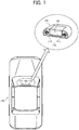
FIG. 1 is a diagram illustrating an external view and example installation of adisparity computation system 100 according to the present embodiment. - As illustrated in the upper part of
FIG. 1 (external view), thedisparity computation system 100 is provided with astereo camera unit 110 and a light detection and ranging (LiDAR) range finder (LiDAR device) 120, which together serve as a sensor device (three-dimensional sensor) that captures the ambient environment as three-dimensional data. Thestereo camera unit 110 includes a monocular camera unit 111 (first image sensing device) and a monocular camera unit 112 (second image sensing device), and the LiDARrange finder 120 is disposed between themonocular camera unit 111 and themonocular camera unit 112. - The
monocular camera units monocular camera units - The LiDAR range finder 120 emits a laser beam and receives the reflected laser beam to measure the distance to the point irradiated with the laser beam (i.e., the distance to an object).
- As illustrated on the lower side of
FIG. 1 (an example of installation), thedisparity computation system 100 is attached, for example, to the inner surface of the windshield of thevehicle 140 at the center. In this configuration, thestereo camera unit 110 and the LiDARrange finder 120 are both attached to thevehicle 140 in a forward-facing manner. In other words, in thevehicle 140 is installed with thedisparity computation system 100 such that the direction in which thestereo camera unit 110 captures an image becomes same as the direction in which the LiDAR range finder 120 emits a laser beam. - Next, the hardware configuration of the
disparity computation system 100 is described. -
FIG. 2 is a diagram illustrating of a hardware configuration of thedisparity computation system 100 according to the present embodiment. - As illustrated in
FIG. 2 , thedisparity computation system 100 is provided with acamera stay 201 and acontrol board housing 202. - On the
camera stay 201, themonocular camera units LiDAR range finder 120 are integrally mounted. Due to this configuration, thedisparity computation system 100 can be downsized and produced at low cost. - In the
control board housing 202, alaser signal processor 240, arangefinder processing unit 250, amemory 260, and a microprocessing unit (MPU) 270 are accommodated. As thelaser signal processor 240 is independently arranged from theLiDAR range finder 120, the size of theLiDAR range finder 120 can be reduced. Due to this configuration, in the present embodiment, theLiDAR range finder 120 can be disposed between themonocular camera unit 111 and themonocular camera unit 112. - In the example illustrated in
FIG. 2 , thelaser signal processor 240 and therangefinder processing unit 250 are configured as separate circuit boards. However, thelaser signal processor 240 and therangefinder processing unit 250 may be configured as a circuit board in common. By so doing, the number of circuit boards is reduced, and the production cost can be reduced. - Next, the elements on the
camera stay 201 side are described in detail. As illustrated inFIG. 2 , themonocular camera unit 111 is provided with a plurality ofcamera lenses 211, animage sensing device 212, and asensor substrate 213. The extraneous light that has passed through thecamera lenses 211 is received by theimage sensing device 212, and is photoelectrically converted in a predetermined frame cycle. The signals that are obtained as a result of the above photoelectric conversion are processed by thesensor substrate 213, and a captured image is generated for each frame. The generated captured image is sequentially sent to therangefinder processing unit 250 as a comparison image. - The
monocular camera unit 112 has the same configuration as that of themonocular camera unit 111, and a captured image that is generated based on a synchronous control signal in synchronization with themonocular camera unit 111 is sequentially sent to therangefinder processing unit 250 as a reference image. - The
LiDAR range finder 120 is provided with alight source driver 231, alaser beam source 232, and aprojector lens 233. Thelight source driver 231 operates according to a synchronous control signal sent from thelaser signal processor 240, and applies modulating electric current (light-source driving signal) to thelaser beam source 232. Due to this configuration, thelaser beam source 232 emits laser beams. The laser beams that are emitted from thelaser beam source 232 are emitted to the outside through theprojector lens 233. - In the present embodiment, an infrared semiconductor laser diode (LD) is used as the
laser beam source 232, and near-infrared light with wavelengths of 800 nanometer (nm) to 950 nm is emitted as a laser beam. Moreover, thelaser beam source 232 periodically emits a laser beam having a pulsed waveform according to the modulating electric current (light-source driving signal) applied by thelight source driver 231. Further, thelaser beam source 232 periodically emits a pulsed laser beam having a short pulse width of about a few nanoseconds to several hundreds of nanoseconds. - The pulsed laser beam that is emitted from the
laser beam source 232 is emitted to the outside through theprojector lens 233 as a projector beam, and then emitted to a predetermined irradiation point (i.e., a predetermined object). Note also that the laser beams that are emitted from thelaser beam source 232 are approximately collimated by theprojector lens 233. Due to this configuration, the irradiation area of the object is controlled to a predetermined minute area. - The
LiDAR range finder 120 further includes aphotoreceptor lens 234, aphotoreceptor 235, and a light-signal amplifier circuit 236. The laser beam that is emitted to a predetermined object uniformly disperses to all directions. Then, only the light components that are reflected and return in the same optical path as the laser beams that were emitted from theLiDAR range finder 120 are guided to thephotoreceptor 235 through thephotoreceptor lens 234 as reflected light. - In the present embodiment, a silicon pin photodiode or an avalanche photodiode is used as the
photoreceptor 235. Thephotoreceptor 235 photoelectrically converts the reflected light to generate a detected laser-beam signal, and the light-signal amplifier circuit 236 amplifies the generated detected laser-beam signal and then sends the amplified detected laser-beam signal to thelaser signal processor 240. - Next, the elements on the
control board housing 202 side are described in detail. Thelaser signal processor 240 calculates and obtains the distance to a predetermined object based on the detected laser-beam signal sent from theLiDAR range finder 120, and sends the calculated and obtained distance data to therangefinder processing unit 250. - The
rangefinder processing unit 250 is configured by, for example, a dedicated integrated circuit such as a field programmable gate array (FPGA) and an application specific integrated circuit (ASIC). Therangefinder processing unit 250 outputs a synchronous control signal for controlling the timing of capturing an image and the timing of laser-beam projection and laser-beam reception to themonocular camera units laser signal processor 240. - Moreover, the
rangefinder processing unit 250 generates a disparity image based on a comparison image sent from themonocular camera unit 111, a reference image sent from themonocular camera unit 112, and distance data sent from thelaser signal processor 240. Then, therangefinder processing unit 250 stores the generated disparity image in thememory 260. - In the
memory 260, a disparity image that is generated by therangefinder processing unit 250 is stored. Moreover, thememory 260 serves as a work area where therangefinder processing unit 250 and theMPU 270 performs various kinds of processes. - The
MPU 270 controls the elements accommodated in thecontrol board housing 202, and analyzes a disparity image stored in thememory 260. - Next, a reference-pixel area that is the to-be-processed pixel area of a reference image and a pixel area of a comparison image are described.
-
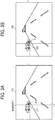
FIG. 3A and FIG. 3B are diagrams illustrating a pixel area in a comparison image and a reference-pixel area in a reference image, respectively, according to the present embodiment. Among these drawings,FIG. 3B illustrates areference image 320 sent from themonocular camera unit 112, according to the present embodiment. In thereference image 320, a pixel area p indicates a reference-pixel area that is currently to be processed by therangefinder processing unit 250. In the example ofFIG. 3B , a reference-pixel area p indicates the pixel area at a position specified by coordinates (x, y). - On the other hand,
FIG. 3A illustrates acomparison image 310 sent from themonocular camera unit 111, according to the present embodiment. In thecomparison image 310, apixel area 311 indicates the pixel area in thecomparison image 310 having the same x-coordinate and y-coordinate as those of the reference-pixel area p in thereference image 320. - A
position 312 indicates the position of a corresponding pixel area that corresponds to the reference-pixel area p in thereference image 320. An object in the real space that lies at the position of the reference-pixel area p (i.e., a portion of the side of another vehicle in the examples ofFIG. 3A and FIG. 3B ) and an object in the real space that lies at theposition 312 of the corresponding pixel area indicate the same position in the real space. However, the position from which thereference image 320 is captured is offset from the position from which thecomparison image 310 is captured in the right and left directions. Due to this configuration, the coordinates of theposition 312 are offset from the coordinates of thepixel area 311 by the amount of disparity in the right and left directions. - Note that as illustrated in
FIG. 3A and FIG. 3B , when the reference-pixel area p is included in an area with a little texture (an area where there are little changes in pixel value among neighboring pixel areas) such as the side of another vehicle, in actuality, it is difficult to precisely extract theposition 312 of the corresponding pixel area that corresponds to the reference-pixel area p. For example, even if a search is performed in a prescribed range of thecomparison image 310 with reference to thepixel area 311 being the starting point, there is a greater likelihood that an irrelevant pixel area is detected in error and theposition 312 of the corresponding pixel area that corresponds to the reference-pixel area p cannot precisely be extracted. - In order to deal with such a situation, the
disparity computation system 100 according to the present embodiment uses the distance data measured by theLiDAR range finder 120 to perform disparity computation. InFIG. 3B , adot 330 schematically indicates the point irradiated with the laser beam by theLiDAR range finder 120 at the timing when thereference image 320 is captured, in an overlapping manner on thereference image 320. - As illustrated in
FIG. 3B , thedot 330 is also positioned within the side of another vehicle, and is at an approximately same position as the reference-pixel area p. In other words, the distance to an object (i.e., a portion of the side of another vehicle) in the real space that lies at the position of the reference-pixel area p can be calculated using the detected laser-beam signal, which is generated from the laser beam reflected from the irradiation point of thedot 330. - In view of the above circumstances, when disparity computation is to be performed in relation to the reference-pixel area p, the
rangefinder processing unit 250 according to the present embodiment makes use of the distance to thedot 330 that has been calculated using a detected laser-beam signal. - Here, the range resolution and the spatial resolution of each three-dimensional sensor is briefly described based on the properties and characteristics of distance data of the three-dimensional sensors (including the
stereo camera unit 110 and the LiDAR range finder 120) provided for thedisparity computation system 100. -
FIG. 4A and FIG. 4B andFIG. 5A and FIG. 5B are diagrams each illustrating the properties and characteristics of distance data obtained by a three-dimensional sensor, according to the present embodiment. - Among these drawings,
FIG. 4A and FIG. 4B are diagrams each illustrating the properties and characteristics of distance data obtained by thestereo camera unit 110, according to the present embodiment. As illustrated inFIG. 4A , the distance data that is calculated and obtained by thestereo camera unit 110 has a higher range resolution as the distance to thestereo camera unit 110 is shorter, and has a lower range resolution as the distance to thestereo camera unit 110 is longer. - In this configuration, the range resolution of the distance data that is calculated and obtained by the
stereo camera unit 110 is not proportionate to the distance to an object, but as illustrated in the graph ofFIG. 4B , rapidly deteriorates when the distance to an object becomes equal to or longer than a certain length (for example, 25 meters (m)). Note also that inFIG. 4B , the horizontal axis indicates the disparity which is indicated by the number of pixels, and the vertical axis indicates the distance to an object. In the graph ofFIG. 4B , the range resolution increases towards the bottom left of the graph, and the range resolution decreases towards the top right of the graph. - In other words, the distance data that is calculated and obtained by the
stereo camera unit 110 has a sufficiently high range resolution when the distance is equal to or shorter than a certain length. As thestereo camera unit 110 has a higher spatial resolution as the range resolution increases, the distance data that is calculated and obtained by thestereo camera unit 110 also has a sufficiently high spatial resolution when the distance is equal to or shorter than a certain length. However, as described above, in the case of thestereo camera unit 110, regardless of the level of the range resolution or spatial resolution, disparity computation cannot effectively be performed for an area that includes an object with a little texture. - By contrast,
FIG. 5A and FIG. 5B are diagrams each illustrating the properties and characteristics of distance data obtained by theLiDAR range finder 120, according to the present embodiment. - As illustrated in
FIG. 5A , the distance data that is obtained by theLiDAR range finder 120 has a constant range resolution regardless of the distance to theLiDAR range finder 120. Accordingly, as illustrated in the graph ofFIG. 5B , the response time since a laser beam is emitted and until the reflected laser beam is received is proportionate to the distance to an object, and the inclination in the graph is substantially constant. InFIG. 5B , the horizontal axis indicates the response time since a laser beam is emitted and until the reflected laser beam is received, and the vertical axis indicates the distance to an object. In the graph ofFIG. 5B , the range resolution increases as the inclination in the graph is smaller, and the range resolution decreases as the inclination in the graph is larger. - In the case of the
LiDAR range finder 120, the response time can be measured in nanoseconds. Due to this configuration, the distance data that is obtained by theLiDAR range finder 120 regardless of to the distance to an object has a higher range resolution than thestereo camera unit 110 in almost any distance. Moreover, in the case of theLiDAR range finder 120, the range resolution is at a constant level regardless of whether the object to be measured is an object with a little texture. - However, in the case of the
LiDAR range finder 120, laser beams are emitted in synchronization with the capturing of thestereo camera unit 110. Due to this configuration, the number of times laser beams can be emitted is limited. For this reason, high spatial resolution cannot be achieved in the distance data that is obtained by theLiDAR range finder 120. - In view of the above properties and characteristics of the three-dimensional sensors provided for the
disparity computation system 100, for example, the distance data that is obtained by theLiDAR range finder 120 may be used in a selective manner for an area where disparity computation cannot effectively performed by thestereo camera unit 110. - However, in such a configuration, the spatial resolution of the relevant area significantly deteriorates compared with the spatial resolution of other areas where disparity computation can effectively performed. This is because, whereas distance data is calculated and obtained on a pixel-by-pixel basis in other areas, distance data is calculated and obtained only for the points irradiated with laser beams in the relevant area.
- In view of the above circumstances, the
disparity computation system 100 according to the present embodiment the distance data that is calculated and obtained by thelaser signal processor 240 is used for disparity computation in order to achieve a high spatial resolution in any area including areas with distance equal to or shorter than a certain length. As described above, by integrating distance data with a high degree of precision into disparity computation, theposition 312 of the corresponding pixel area can accurately be extracted and disparity computation can precisely be performed even in areas where it used to be difficult to perform effective disparity computation. -
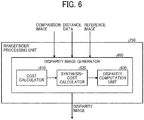
FIG. 6 is a diagram illustrating a functional configuration of therangefinder processing unit 250, according to the present embodiment. Note thatFIG. 6 does not illustrate the entire functional configuration of therangefinder processing unit 250, but illustrates only the functional configuration of the processes related to disparity computation. The other functional configuration (for example, a function of transmitting a synchronous control signal) is omitted inFIG. 6 . - As illustrated in
FIG. 6 , therangefinder processing unit 250 includes adisparity image generator 600 as a functional configuration for the processes related to disparity computation. Thedisparity image generator 600 further includes acost calculator 610, a synthesis-cost calculator 620, and adisparity computation unit 630. - The
cost calculator 610 is an example of a calculation unit, and thecost calculator 610 obtains thereference image 320 from themonocular camera unit 112 and obtains thecomparison image 310 from themonocular camera unit 111. Moreover, thecost calculator 610 extracts the reference-pixel area p from thereference image 320, and calculates a cost C with reference to a plurality of pixel areas in thecomparison image 310. The cost C is a parameter that indicates the degree of dissimilarity between the reference-pixel area p and a plurality of pixel areas in thecomparison image 310. - Further, the
cost calculator 610 obtains the distance data of thedot 330 from thelaser signal processor 240, and calculates and obtains a cost Cl. The cost Cl is a parameter that indicates the degree of dissimilarity between the reference-pixel area p and the pixel area that is at the position derived from the obtained distance data in thecomparison image 310. - Then, the
cost calculator 610 adds up the weighting based on the calculated cost C (first cost) and cost Cl (second cost) to calculate and obtain weighted costs for a plurality of pixel areas in thecomparison image 310. Further, thecost calculator 610 notifies the synthesis-cost calculator 620 of the obtained weighted costs. In other words, each weighted cost indicates a cost (degree of dissimilarity) combined by the synthesis-cost calculator 620. - The synthesis-
cost calculator 620 combines the weighted costs of a plurality of pixel areas provided by thecost calculator 610 to calculate a synthesis cost S (p, d) and obtain a result of the combining processes. The synthesis-cost calculator 620 adopts, for example, a processing method such as semi-global matching (SGM) to calculate and obtain a plurality of route costs Lr, and gathers each one of the route costs Lr to the reference-pixel area p. By performing these processes as described above, a synthesis cost S (p, d) is calculated and obtained. - The
disparity computation unit 630 is an example of a computation unit, and extracts the corresponding pixel area in thecomparison image 310 that corresponds to the reference-pixel area p based on the synthesis cost S calculated by the synthesis-cost calculator 620, and computes a disparity of the reference-pixel area p. - Note that the
cost calculator 610 and the synthesis-cost calculator 620 perform similar processes for other reference-pixel areas in thereference image 320. Then, thedisparity computation unit 630 computes a disparity for each one of the reference-pixel areas. Moreover, thedisparity computation unit 630 generates a disparity image based on the computed disparities for a plurality of reference-pixel areas, and stores the generated disparity image in thememory 260. -
FIG. 7 is a diagram illustrating a detailed functional configuration of thecost calculator 610, according to the present embodiment. - As illustrated in
FIG. 7 , thecost calculator 610 includes a reference-image acquisition unit 701, a comparison-image acquisition unit 702, a cost-C calculator 703, and a cost-C adjuster 704. Moreover, thecost calculator 610 includes a distance-data acquisition unit 711, a cost-Cl calculator 712, and aweighting adder 720. - The reference-
image acquisition unit 701 obtains thereference image 320 from themonocular camera unit 112, and extracts the reference-pixel area p from the obtainedreference image 320. The comparison-image acquisition unit 702 obtains thecomparison image 310 from themonocular camera unit 111. - The cost-
C calculator 703 calculates the cost C (p, d) of the reference-pixel area p. -
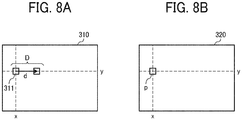
FIG. 8A and FIG. 8B are diagrams illustrating a method of calculating the cost C (p, d), according to the present embodiment. - As illustrated in
FIG. 8A , the cost-C calculator 703 varies the amount of shift d within a predetermined range (0 to D) to shift thepixel area 311 in sequence within thecomparison image 310. Then, the cost-C calculator 703 calculates and obtains a cost C (p, d) as a degree of dissimilarity between the pixel value of thepixel area 311 at each one of the positions of the amounts of shift d, and the pixel value of the reference-pixel area p in thereference image 320 illustrated inFIG. 8B . - Note that the cost C (p, d) is calculated using a known matching method such as the sum of absolute difference (SAD) and the sum of squared difference (SSD) in which a cost is calculated based on the difference in pixel value among pixel areas. Due to this configuration, the calculated cost C (p, d) has a smaller value as the pixel value is closer to the pixel value of the reference-pixel area p, and has a larger value as the pixel value is farther from the pixel value of the reference-pixel area p.
- As illustrated in
FIG. 7 , the cost-C adjuster 704 adjusts the cost C (p, d) of the reference-pixel area p calculated by the cost-C calculator 703 based on the degree of reliability. The cost-C adjuster 704 performsadjustment using Formula 1 below, to obtain the adjusted cost C' (p, d).
[Formula 1]
- In this formula, "D" indicates the maximum value of an amount of shift, and "k" indicates the count value of an amount of shift. Moreover, Q(p) indicates the degree of reliability of the cost C (p, d) of the reference-pixel area p. The degree of reliability Q(p) is calculated, for example, by using
Formula 2 below.
[Formula 2]
- In this formula, Cmin1 and Cmin2 indicate the lowest cost and the second lowest cost among a plurality of costs C (p, d) calculated by varying the amount of shift d within a predetermined range (0 to D). Note also that the degree of reliability Q(p) that is calculated based on
Formula 2 as above is used inFormula 1 as above upon normalizing the value calculated based on Cmin1 and Cmin2 to be greater than 0 and less than 1.0 and adjusting the normalized value so as to become closer to 1.0 as the degree of reliability is higher. - The adjusted cost C' (p, d) adjusted by the cost-
C adjuster 704 is, for example, in the reference-pixel area p is included in an area with a little texture (an area where there are little changes in pixel value among neighboring pixel areas), and when the degree of reliability Q(p) is low, takes a larger value. - The distance-
data acquisition unit 711 is an example of an acquisition unit, and obtains the distance data from thelaser signal processor 240. In the present embodiment, the distance data obtained from thelaser signal processor 240 is referred to as Zl. The distance-data acquisition unit 711 notifies the cost-Cl calculator 712 of the obtained distance data Zl. - The cost-Cl calculator 712 calculates and obtains a cost Cl based on the distance data Zl provided by the distance-
data acquisition unit 711. More specifically, the cost-Cl calculator 712 firstly calculates an amount of shift dl based on the distance data Zl using Formula 3 below. Accordingly, the pixel area that is at the position derived from the distance data Zl in thecomparison image 310 is extracted.
[Formula 3]
- In
Formula 3 as above, "B" indicates the base-line length between thecamera lenses 211 and thecamera lenses 221, and "f" indicates the focal length between thecamera lenses 211 and thecamera lenses 221. - Subsequently, the cost-Cl calculator 712 calculates a cost Cl (p, dl) at the position of the amount of shift dl. In a similar manner to the calculation of a cost C (p, d) as above, the cost-Cl calculator 712 calculates a cost Cl (p, dl) as a degree of dissimilarity between the pixel value of the
pixel area 311 at the position of the amount of shift dl and the pixel value of the reference-pixel area p. - The
weighting adder 720 adds up the weighting using the adjusted cost C' (p, d) adjusted by the cost-C adjuster 704 and the cost Cl (p, dl) calculated by the cost-Cl calculator 712, based onFormula 4 below, to calculate a weighted cost.
[Formula 4]
- In this formula, wd is a weighting factor indicating to prioritize which one of the adjusted cost C' (p, d) adjusted by the cost-
C adjuster 704 and the cost Cl (p, dl) calculated by the cost-Cl calculator 712. When the adjusted cost C' (p, d) adjusted by the cost-C adjuster 704 is to be prioritized, the value of wd is increased. By contrast, when the cost Cl (p, dl) calculated by the cost-Cl calculator 712 is to be prioritized, the value of wd is reduced. - More specifically, when the amount of shift d≠dl, the value of wd is increased. Due to this configuration, the weighted cost of the pixel area where the amount of shift d≠dl, in the
pixel area 311 of thecomparison image 310, can further be increased. Note also that the adjusted cost C' (p, d) has a larger value than that of, for example, an area with a little texture, and the weighted cost of the pixel area where the amount of shift d≠dl has an even larger value when the value of wd is increased and the adjusted cost C' (p, d) is prioritized. - By contrast, when the amount of shift d=dl, the value of wd is reduced. Due to this configuration, the weighted cost of the pixel area where the amount of shift d=dl, in the
pixel area 311 of thecomparison image 310, can further be reduced. Note also that the cost Cl (p, dl) calculated by the cost-Cl calculator 712 has a smaller value than that of the adjusted cost C' (p, d) calculated by the cost-C adjuster 704. Due to this configuration, when the value of wd is reduced and the cost Cl (p, dl) calculated by the cost-Cl calculator 712 is prioritized, the weighted cost of the pixel area where the amount of shift d=dl has an even smaller value. - In other words, due to
Formula 4, the difference in cost between the pixel area where the amount of shift d=dl and the other pixel areas can be made more significant as a weighted cost. - As a result, when corresponding pixel area is to be extracted based on the synthesis cost S calculated by the synthesis-
cost calculator 620, it becomes easier to extract the pixel area in thecomparison image 310 where d=dl. In other words, theposition 312 of the corresponding pixel area that corresponds to the reference-pixel area p can precisely be extracted. - In
Formula 4 as above, the value of wd may be a fixed value, or may vary according to the value of distance data Zl. Alternatively, the value of wd may vary according to the ambient environment (for example, depending on whether it is during the daytime or nighttime). -
FIG. 9 is a diagram illustrating a detailed functional configuration of the synthesis-cost calculator 620, according to the present embodiment. As illustrated inFIG. 9 , the synthesis-cost calculator 620 includes a route-cost calculator 901, and a synthesis-cost S calculator 902. - Once the route-
cost calculator 901 obtains a weighted cost from theweighting adder 720, the route-cost calculator 901 calculates a route cost Lr (p, d) based onFormula 5 below.
[Formula 5]
- Note that
Formula 5 above is a formula where the cost C (p, d) is replaced with a weighted cost in a commonly-used formula for route costs Lr that adopts semi-global matching (SGM). Moreover, inFormula 5 as above, P1 and P2 are fixed parameters. - According to
Formula 5 as above, the route-cost calculator 901 adds a minimum value for a route cost Lr in the pixel areas of in r-directions, as illustrated inFIG. 10 , to the weighted cost of the reference-pixel area p, to calculate a route cost Lr (p, d). -
FIG. 10 is a diagram illustrating r-directions referred to in the calculation of a route cost Lr (p, d), according to the present embodiment. - As illustrated in
FIG. 10 , the route-cost calculator 901 calculates a route cost Lr (for example, Lr135 (p-2r, d)) for the pixel area at the farthest edge in an r-direction of the reference-pixel area p (for example, r135 direction). Subsequently, the route-cost calculator 901 calculates a route cost Lr (Lr135 (p-r, d)) along the r-direction. In the present embodiment, the route-cost calculator 901 repeats the above processes to calculate and obtain route cost Lr (for example, Lr135 (p, d)) for eight directions. Accordingly, the route costs Lr0 (p, d) to Lr135 (p, d) are obtained. - The synthesis-
cost S calculator 902 usesFormula 6 to calculate a synthesis cost S (p, d) based on the eight-directional route costs Lr0 (p, d) to Lr315 (p, d) calculated by the route-cost calculator 901.
[Formula 6]
- The synthesis-
cost S calculator 902 notifies thedisparity computation unit 630 of the calculated synthesis cost S (p, d). - The
disparity computation unit 630 obtains a synthesis cost S (p, d) in the reference-pixel area p provided by the synthesis-cost S calculator 902. -
FIG. 11 is a diagram illustrating a result of calculating the synthesis cost S in the reference-pixel area p, according to the present embodiment. - The
disparity computation unit 630 computes and obtains the amount of shift dmin where the synthesis cost S (p, d) becomes smallest, within a predetermined range (0 to D), to extract the corresponding pixel area in thecomparison image 310. Due to this configuration, thedisparity computation unit 630 can obtain an amount of shift dmin as a result of the disparity computation performed for between the extracted corresponding pixel area and the reference-pixel area p. - Note also that the
disparity computation unit 630 performs similar processes for other reference-pixel areas in thereference image 320, and obtains a result of the disparity computation. As a result, a disparity image is generated, and the generated disparity image is stored in thememory 260. - Next, the processing flow of the disparity image generating processes by the
disparity image generator 600 is described. -
FIG. 12 is a flowchart of the disparity image generating processes by thedisparity image generator 600, according to the present embodiment. - The flowchart illustrated in
FIG. 12 depicts the processes of computing a disparity for one reference-pixel area p, and thedisparity image generator 600 executes the processes in the flowchart ofFIG. 12 for a plurality of reference-pixel areas to generate a disparity image. - In a step S1201, the reference-
image acquisition unit 701 obtains thereference image 320 to extract a reference-pixel area p. - In a step S1202, the cost-
C calculator 703 calculates and obtains the cost C (p, d) based on the pixel value of thepixel area 311 at the position of the amount of shift d in thecomparison image 310 obtained by the comparison-image acquisition unit 702, and the pixel value of the reference-pixel area p. - In a step S1203, The cost-
C adjuster 704 adjusts the calculated cost C (p, d) based on the degree of reliability Q(p) to obtain an adjusted cost C' (p, d). - In a step S1204, the distance-
data acquisition unit 711 obtains the distance data Zl that indicates the distance to an object in the real space that lies at the position of the reference-pixel area p. - In a step S1205, the cost-Cl calculator 712 calculates and obtains a cost Cl based on the distance data Zl obtained by the distance-
data acquisition unit 711. - In a step S1206, the
weighting adder 720 adds up the weighting of the adjusted cost C' (p, d) adjusted by the cost-C adjuster 704 and the cost Cl (p, d) calculated by the cost-Cl calculator 712 to calculate a weighted cost. - In a step S1207, the route-
cost calculator 901 calculates and obtains route costs Lr (p, d) using the calculated weighted cost. - In a step S1208, the synthesis-
cost S calculator 902 calculates and obtains a synthesis cost S (p, d) based on the obtained route costs Lr (p, d). - In a step S1209, the
disparity computation unit 630 calculates the amount of shift (dmin) where the synthesis cost S (p, d) becomes smallest. As a result, extract the corresponding pixel area from thecomparison image 310 and obtain a result of the disparity computation performed for between the extracted corresponding pixel area and the reference-pixel area p. - As described above, in the
disparity computation system 100 according to the present embodiment, theLiDAR range finder 120 measures the distance to an object in the real space that lies at the position of the reference-pixel area p to obtain the distance data Zl. A cost Cl is calculated and obtained based on the amount of shift dl that corresponds to the obtained distance data Zl. The weighting of the adjusted cost C' that is obtained by adjusting the cost C of the reference-pixel area p based on the degree of reliability and the weighting of the cost Cl that is calculated based on the distance data Zl are added up using a weighting factor wd, to calculate weighted costs. The calculated weighted costs are combined to obtain a synthesis cost S. The corresponding pixel area in the comparison image that corresponds to the reference-pixel area is extracted based on the obtained synthesis cost S, and a disparity of the reference-pixel area p is computed. - Due to the configuration as described above, a lower weighted cost than the weighted costs of other pixel areas can be calculated for the pixel area in the comparison image that is at the position derived from the distance data measured by the LiDAR range finder. Due to this configuration, when a corresponding pixel area is to be extracted, it becomes easier to extract the pixel area as a corresponding pixel area by using a synthesis cost obtained by combining the weighted costs, even if the area is, for example, a pixel area with a little texture.
- In other words, with the
disparity computation system 100 according to the present embodiment, even in areas with a little texture where it used to be difficult to extract a corresponding pixel area, a corresponding pixel area can be extracted with precision, and disparity computation can be performed with a high degree of precision. - In the embodiment described above, cases in which a cost C is calculated for each pixel area are described. However, a cost C may be calculated for every pixel. In such a configuration, the
cost calculator 610 extracts a reference-pixel from thereference image 320, and calculates a cost C with reference to each pixel of thecomparison image 310. In other words, a "pixel area" in the embodiment as described above includes one or a plurality of pixels. - In the embodiment as described above, cases in which the
stereo camera unit 110 and theLiDAR range finder 120 are formed as a single integrated unit are described. However, thestereo camera unit 110 and theLiDAR range finder 120 may be configured independently. - In the embodiment described above, cases in which the
stereo camera unit 110 and theLiDAR range finder 120 are combined to server as a three-dimensional sensor are described. However, a different three-dimensional sensor may be combined with thestereo camera unit 110 to configure adisparity computation system 100. Such a different three-dimensional sensor may be, for example, a millimeter-wave radar device. - In the embodiment described above, the
disparity computation system 100 includes a three-dimensional sensor (including thestereo camera unit 110 and the LiDAR range finder 120) and thecontrol board housing 202. However, it is not always necessary for thedisparity computation system 100 to include a three-dimensional sensor, but it is satisfactory as long as at least a circuit board that serves as therangefinder processing unit 250 is included in thecontrol board housing 202. - In the embodiment described above, the
rangefinder processing unit 250 is configured by a dedicated integrated circuit. However, for example, a recording medium storing the program codes of software that implements the functions of therangefinder processing unit 250 may be provided for thedisparity computation system 100 to implement the functions of therangefinder processing unit 250. In such a configuration, a computer of thedisparity computation system 100 reads and executes the program codes stored in a recording medium, thereby implementing the functions of therangefinder processing unit 250. - In the embodiment described above, the
disparity computation system 100 is installed in thevehicle 140. However, thedisparity computation system 100 may be installed, for example, in a motorbike, a bicycle, a wheelchair, and an agricultural cultivator. Alternatively, thedisparity computation system 100 may be installed, for example, in a mobile object such as a robot, or in an industrial robot that is disposed in a fixed manner in factory automation (FA). - Numerous additional modifications and variations are possible in light of the above teachings. It is therefore to be understood that within the scope of the appended claims, the disclosure of the present invention may be practiced otherwise than as specifically described herein. For example, elements and/or features of different illustrative embodiments may be combined with each other and/or substituted for each other within the scope of this disclosure and appended claims.
- The present invention can be implemented in any convenient form, for example using dedicated hardware, or a mixture of dedicated hardware and software. The present invention may be implemented as computer software implemented by one or more networked processing apparatuses. The network can comprise any conventional terrestrial or wireless communications network, such as the Internet. The processing apparatuses can compromise any suitably programmed apparatuses such as a general purpose computer, personal digital assistant, mobile telephone (such as a WAP or 3G-compliant phone) and so on. Since the present invention can be implemented as software, each and every aspect of the present invention thus encompasses computer software implementable on a programmable device. The computer software can be provided to the programmable device using any conventional carrier medium. The carrier medium can compromise a transient carrier medium such as an electrical, optical, microwave, acoustic or radio frequency signal carrying the computer code. An example of such a transient medium is a TCP/IP signal carrying computer code over an IP network, such as the Internet. The carrier medium can also comprise a storage medium for storing processor readable code such as a floppy disk, hard disk, CD ROM, magnetic tape device or solid state memory device.
- The hardware platform includes any desired kind of hardware resources including, for example, a central processing unit (CPU), a random access memory (RAM), and a hard disk drive (HDD). The CPU may be implemented by any desired kind of any desired number of processor. The RAM may be implemented by any desired kind of volatile or non-volatile memory. The HDD may be implemented by any desired kind of non-volatile memory capable of storing a large amount of data. The hardware resources may additionally include an input device, an output device, or a network device, depending on the type of the apparatus. Alternatively, the HDD may be provided outside of the apparatus as long as the HDD is accessible. In this example, the CPU, such as a cache memory of the CPU, and the RAM may function as a physical memory or a primary memory of the apparatus, while the HDD may function as a secondary memory of the apparatus.
Claims (11)
- A disparity computation system (100) comprising:an acquisition unit (711) configured to obtain distance data (Zl) that indicates distance to an object in real space that lies at a position of a reference-pixel area (p) in a reference image (320);a calculation unit (610) configured to calculate a degree of dissimilarity (C) between the reference-pixel area (p) and a plurality of pixel areas in a comparison image (310); anda computation unit (630) configured to compute a disparity from the calculated degree of dissimilarity (C),wherein the calculation unit (610) calculates the degree of dissimilarity (Cl) using a first value calculated from the reference image (320) and the comparison image (310) and a second value calculated from the comparison image (310) and the distance data (Zl).
- The disparity computation system (100) according to claim 1, wherein the computation unit (630) extracts a corresponding pixel area in the comparison image (310) that corresponds to the reference-pixel area (p) based on a synthesis result (S) obtained by combining the calculated degree of dissimilarity (C, Cl), and computes a disparity of the reference-pixel area (p).
- The disparity computation system (100) according to claim 1 or 2, wherein
the second value indicates the degree of dissimilarity (Cl) with a pixel area (311) that is at a position derived from the distance data (Zl) in the comparison image (310),
the first value indicates the degree of dissimilarity (C) with other pixel areas in the comparison image (310), and
the calculation unit (610) controls the first value to be smaller than the second value when calculating the degree of dissimilarity (C) between the reference-pixel area (p) and the plurality of pixel areas in the comparison image (310). - The disparity computation system (100) according to any one of claims 1 to 3, wherein
the first value is calculated based on a difference between a pixel value of the reference-pixel area (p) and pixel values of the plurality of pixel areas in the comparison image (310),
the second value is calculated based on a difference between a pixel value of the reference-pixel area (p) and a pixel value of a pixel area (311) that is at a position derived from the distance data (Zl) in the comparison image (310),
the calculation unit (610) adds up weighting of the first value and the second value to calculate the degree of dissimilarity,
when calculating the degree of dissimilarity (C) with the other pixel areas in the comparison image (310), the calculation unit (610) adds up the weighting of the first value and the second value prioritizing the first value, and
when calculating the degree of dissimilarity (Cl) with a pixel area (311) that is at a position derived from the distance data (Zl) in the comparison image (310), the calculation unit (610) adds up the weighting of the first value and the second value prioritizing the second value. - The disparity computation system (100) according to claim 4, wherein the calculation unit (610) changes a weighting factor used for adding up the weighting of the first value and the second value according to the distance data (Zl) or an ambient environment when the distance data (Zl) is obtained.
- The disparity computation system (100) according to any one of claims 1 to 5, further comprising:a first image sensing device (111) configured to capture the reference image (320);a second image sensing device (112) configured to capture the comparison image (310); anda LiDAR device (120) configured to measure distance to the object.
- A mobile object (140) comprising the disparity computation system (100) according to any one of claims 1 to 6.
- A disparity computation device (100) comprising:the disparity computation system (100) according to claim 1; andan imaging device (111, 112) configured to capture an object from at least two different positions.
- The disparity computation device (100) according to claim 8, wherein the calculation unit (610) controls the second value to have a greater impact on the degree of dissimilarity than the first value when calculating the degree of dissimilarity upon adding up weighting of the first value and the second value.
- A method of computing a disparity, the method comprising:obtaining (S1204) distance data (Zl) that indicates distance to an object in real space that lies at a position of a reference-pixel area (p) in a reference image (320);calculating (S1202) a degree of dissimilarity (C) between the reference-pixel area (p) and a plurality of pixel areas in a comparison image (310);extracting a corresponding pixel area in the comparison image (310) that corresponds to the reference-pixel area (p), based on a synthesis result (S) obtained by combining the calculated degree of dissimilarity (C); andcomputing (S1209) a disparity of the reference-pixel area (p),wherein the calculating (S1202) includes calculating the degree of dissimilarity (C) between the reference-pixel area (p) and the plurality of pixel areas in the comparison image (310) such that the degree of dissimilarity (Cl) with a pixel area (311) that is at a position derived from the distance data (Zl) in the comparison image (310) has a lower value than the degree of dissimilarity (C) with other pixel areas in the comparison image (310).
- A carrier means carrying computer readable code for controlling a computer system to carry out the method of claim 10.
Applications Claiming Priority (1)
| Application Number | Priority Date | Filing Date | Title |
|---|---|---|---|
| JP2016145170A JP6776692B2 (en) | 2016-07-25 | 2016-07-25 | Parallax calculation system, mobiles and programs |
Publications (2)
| Publication Number | Publication Date |
|---|---|
| EP3276576A1 true EP3276576A1 (en) | 2018-01-31 |
| EP3276576B1 EP3276576B1 (en) | 2019-06-26 |
Family
ID=59676941
Family Applications (1)
| Application Number | Title | Priority Date | Filing Date |
|---|---|---|---|
| EP17182204.2A Active EP3276576B1 (en) | 2016-07-25 | 2017-07-19 | Disparity estimation by fusion of range data and stereo data |
Country Status (2)
| Country | Link |
|---|---|
| EP (1) | EP3276576B1 (en) |
| JP (1) | JP6776692B2 (en) |
Cited By (4)
| Publication number | Priority date | Publication date | Assignee | Title |
|---|---|---|---|---|
| EP3540467A3 (en) * | 2018-03-13 | 2019-12-25 | Ricoh Company, Ltd. | Range finding system, range finding method, in-vehicle device, and vehicle |
| CN111260597A (en) * | 2020-01-10 | 2020-06-09 | 大连理工大学 | Parallax image fusion method of multiband stereo camera |
| EP3686631A1 (en) * | 2019-01-22 | 2020-07-29 | Ricoh Company, Ltd. | Range finding method, range finding apparatus, and range finding system |
| US11391840B2 (en) | 2018-06-25 | 2022-07-19 | Ricoh Company, Ltd. | Distance-measuring apparatus, mobile object, distance-measuring method, and distance measuring system |
Family Cites Families (2)
| Publication number | Priority date | Publication date | Assignee | Title |
|---|---|---|---|---|
| KR101862199B1 (en) * | 2012-02-29 | 2018-05-29 | 삼성전자주식회사 | Method and Fusion system of time-of-flight camera and stereo camera for reliable wide range depth acquisition |
| JP6476831B2 (en) * | 2013-12-26 | 2019-03-06 | 株式会社リコー | Parallax calculation system, information processing apparatus, information processing method, and program |
-
2016
- 2016-07-25 JP JP2016145170A patent/JP6776692B2/en active Active
-
2017
- 2017-07-19 EP EP17182204.2A patent/EP3276576B1/en active Active
Non-Patent Citations (2)
| Title |
|---|
| JAN FISCHER ET AL: "Combination of Time-of-Flight depth and stereo using semiglobal optimization", ROBOTICS AND AUTOMATION (ICRA), 2011 IEEE INTERNATIONAL CONFERENCE ON, IEEE, 9 May 2011 (2011-05-09), pages 3548 - 3553, XP032033860, ISBN: 978-1-61284-386-5, DOI: 10.1109/ICRA.2011.5979999 * |
| NAIR RAHUL ET AL: "A Survey on Time-of-Flight Stereo Fusion", 2013, NETWORK AND PARALLEL COMPUTING; [LECTURE NOTES IN COMPUTER SCIENCE; LECT.NOTES COMPUTER], SPRINGER INTERNATIONAL PUBLISHING, CHAM, PAGE(S) 105 - 127, ISBN: 978-3-642-24392-9, ISSN: 0302-9743, XP047269358 * |
Cited By (6)
| Publication number | Priority date | Publication date | Assignee | Title |
|---|---|---|---|---|
| EP3540467A3 (en) * | 2018-03-13 | 2019-12-25 | Ricoh Company, Ltd. | Range finding system, range finding method, in-vehicle device, and vehicle |
| US11391840B2 (en) | 2018-06-25 | 2022-07-19 | Ricoh Company, Ltd. | Distance-measuring apparatus, mobile object, distance-measuring method, and distance measuring system |
| EP3686631A1 (en) * | 2019-01-22 | 2020-07-29 | Ricoh Company, Ltd. | Range finding method, range finding apparatus, and range finding system |
| US11366229B2 (en) | 2019-01-22 | 2022-06-21 | Ricoh Company, Ltd. | Range finding method, range finding apparatus, and range finding system |
| CN111260597A (en) * | 2020-01-10 | 2020-06-09 | 大连理工大学 | Parallax image fusion method of multiband stereo camera |
| CN111260597B (en) * | 2020-01-10 | 2021-12-03 | 大连理工大学 | Parallax image fusion method of multiband stereo camera |
Also Published As
| Publication number | Publication date |
|---|---|
| JP6776692B2 (en) | 2020-10-28 |
| JP2018017506A (en) | 2018-02-01 |
| EP3276576B1 (en) | 2019-06-26 |
Similar Documents
| Publication | Publication Date | Title |
|---|---|---|
| EP3588141B1 (en) | Distance-measuring apparatus, mobile object, distance-measuring method, and distance-measuring system | |
| EP3264364B1 (en) | Method and apparatus for obtaining range image with uav, and uav | |
| EP3276576B1 (en) | Disparity estimation by fusion of range data and stereo data | |
| US11250288B2 (en) | Information processing apparatus and information processing method using correlation between attributes | |
| RU2529594C1 (en) | Calibration device, distance measurement system, calibration method and calibration programme | |
| CN108377380B (en) | Image scanning system and method thereof | |
| US11175390B2 (en) | Real-time estimation of DC bias and noise power of light detection and ranging (LiDAR) | |
| JP6753107B2 (en) | Distance measuring device, distance measuring method and program | |
| EP3279691B1 (en) | Rangefinder based on parallax calculation | |
| CN110285788B (en) | ToF camera and design method of diffractive optical element | |
| JP7131180B2 (en) | Ranging device, ranging method, program, moving body | |
| CN113466836A (en) | Distance measurement method and device and laser radar | |
| CN112106111A (en) | Calibration method, calibration equipment, movable platform and storage medium | |
| Portugal-Zambrano et al. | Robust range finder through a laser pointer and a webcam | |
| US20230273321A1 (en) | 3D Image Sensor Ranging System, and Ranging Method Using Same | |
| Teizer et al. | Range imaging as emerging optical three-dimension measurement technology | |
| WO2022195954A1 (en) | Sensing system | |
| US20240111052A1 (en) | Information processing device, information processing method, and program | |
| US20230057655A1 (en) | Three-dimensional ranging method and device | |
| CN113792645A (en) | AI eyeball fusing image and laser radar | |
| US10698111B2 (en) | Adaptive point cloud window selection | |
| KR102106889B1 (en) | Mini Integrated-control device | |
| US20220155416A1 (en) | Laser emission control in light detection and ranging (lidar) systems | |
| WO2023095375A1 (en) | Three-dimensional model generation method and three-dimensional model generation device | |
| JP7310587B2 (en) | Ranging device, ranging method, and ranging program |
Legal Events
| Date | Code | Title | Description |
|---|---|---|---|
| PUAI | Public reference made under article 153(3) epc to a published international application that has entered the european phase |
Free format text: ORIGINAL CODE: 0009012 |
|
| STAA | Information on the status of an ep patent application or granted ep patent |
Free format text: STATUS: REQUEST FOR EXAMINATION WAS MADE |
|
| 17P | Request for examination filed |
Effective date: 20170719 |
|
| AK | Designated contracting states |
Kind code of ref document: A1 Designated state(s): AL AT BE BG CH CY CZ DE DK EE ES FI FR GB GR HR HU IE IS IT LI LT LU LV MC MK MT NL NO PL PT RO RS SE SI SK SM TR |
|
| AX | Request for extension of the european patent |
Extension state: BA ME |
|
| GRAP | Despatch of communication of intention to grant a patent |
Free format text: ORIGINAL CODE: EPIDOSNIGR1 |
|
| STAA | Information on the status of an ep patent application or granted ep patent |
Free format text: STATUS: GRANT OF PATENT IS INTENDED |
|
| INTG | Intention to grant announced |
Effective date: 20190301 |
|
| GRAS | Grant fee paid |
Free format text: ORIGINAL CODE: EPIDOSNIGR3 |
|
| GRAA | (expected) grant |
Free format text: ORIGINAL CODE: 0009210 |
|
| STAA | Information on the status of an ep patent application or granted ep patent |
Free format text: STATUS: THE PATENT HAS BEEN GRANTED |
|
| AK | Designated contracting states |
Kind code of ref document: B1 Designated state(s): AL AT BE BG CH CY CZ DE DK EE ES FI FR GB GR HR HU IE IS IT LI LT LU LV MC MK MT NL NO PL PT RO RS SE SI SK SM TR |
|
| REG | Reference to a national code |
Ref country code: GB Ref legal event code: FG4D |
|
| REG | Reference to a national code |
Ref country code: CH Ref legal event code: EP |
|
| REG | Reference to a national code |
Ref country code: AT Ref legal event code: REF Ref document number: 1149194 Country of ref document: AT Kind code of ref document: T Effective date: 20190715 |
|
| REG | Reference to a national code |
Ref country code: DE Ref legal event code: R096 Ref document number: 602017004791 Country of ref document: DE |
|
| REG | Reference to a national code |
Ref country code: IE Ref legal event code: FG4D |
|
| REG | Reference to a national code |
Ref country code: NL Ref legal event code: MP Effective date: 20190626 |
|
| PG25 | Lapsed in a contracting state [announced via postgrant information from national office to epo] |
Ref country code: NO Free format text: LAPSE BECAUSE OF FAILURE TO SUBMIT A TRANSLATION OF THE DESCRIPTION OR TO PAY THE FEE WITHIN THE PRESCRIBED TIME-LIMIT Effective date: 20190926 Ref country code: FI Free format text: LAPSE BECAUSE OF FAILURE TO SUBMIT A TRANSLATION OF THE DESCRIPTION OR TO PAY THE FEE WITHIN THE PRESCRIBED TIME-LIMIT Effective date: 20190626 Ref country code: AL Free format text: LAPSE BECAUSE OF FAILURE TO SUBMIT A TRANSLATION OF THE DESCRIPTION OR TO PAY THE FEE WITHIN THE PRESCRIBED TIME-LIMIT Effective date: 20190626 Ref country code: SE Free format text: LAPSE BECAUSE OF FAILURE TO SUBMIT A TRANSLATION OF THE DESCRIPTION OR TO PAY THE FEE WITHIN THE PRESCRIBED TIME-LIMIT Effective date: 20190626 Ref country code: LT Free format text: LAPSE BECAUSE OF FAILURE TO SUBMIT A TRANSLATION OF THE DESCRIPTION OR TO PAY THE FEE WITHIN THE PRESCRIBED TIME-LIMIT Effective date: 20190626 Ref country code: HR Free format text: LAPSE BECAUSE OF FAILURE TO SUBMIT A TRANSLATION OF THE DESCRIPTION OR TO PAY THE FEE WITHIN THE PRESCRIBED TIME-LIMIT Effective date: 20190626 |
|
| REG | Reference to a national code |
Ref country code: LT Ref legal event code: MG4D |
|
| PG25 | Lapsed in a contracting state [announced via postgrant information from national office to epo] |
Ref country code: LV Free format text: LAPSE BECAUSE OF FAILURE TO SUBMIT A TRANSLATION OF THE DESCRIPTION OR TO PAY THE FEE WITHIN THE PRESCRIBED TIME-LIMIT Effective date: 20190626 Ref country code: RS Free format text: LAPSE BECAUSE OF FAILURE TO SUBMIT A TRANSLATION OF THE DESCRIPTION OR TO PAY THE FEE WITHIN THE PRESCRIBED TIME-LIMIT Effective date: 20190626 Ref country code: BG Free format text: LAPSE BECAUSE OF FAILURE TO SUBMIT A TRANSLATION OF THE DESCRIPTION OR TO PAY THE FEE WITHIN THE PRESCRIBED TIME-LIMIT Effective date: 20190926 Ref country code: GR Free format text: LAPSE BECAUSE OF FAILURE TO SUBMIT A TRANSLATION OF THE DESCRIPTION OR TO PAY THE FEE WITHIN THE PRESCRIBED TIME-LIMIT Effective date: 20190927 |
|
| REG | Reference to a national code |
Ref country code: AT Ref legal event code: MK05 Ref document number: 1149194 Country of ref document: AT Kind code of ref document: T Effective date: 20190626 |
|
| PG25 | Lapsed in a contracting state [announced via postgrant information from national office to epo] |
Ref country code: PT Free format text: LAPSE BECAUSE OF FAILURE TO SUBMIT A TRANSLATION OF THE DESCRIPTION OR TO PAY THE FEE WITHIN THE PRESCRIBED TIME-LIMIT Effective date: 20191028 Ref country code: AT Free format text: LAPSE BECAUSE OF FAILURE TO SUBMIT A TRANSLATION OF THE DESCRIPTION OR TO PAY THE FEE WITHIN THE PRESCRIBED TIME-LIMIT Effective date: 20190626 Ref country code: EE Free format text: LAPSE BECAUSE OF FAILURE TO SUBMIT A TRANSLATION OF THE DESCRIPTION OR TO PAY THE FEE WITHIN THE PRESCRIBED TIME-LIMIT Effective date: 20190626 Ref country code: SK Free format text: LAPSE BECAUSE OF FAILURE TO SUBMIT A TRANSLATION OF THE DESCRIPTION OR TO PAY THE FEE WITHIN THE PRESCRIBED TIME-LIMIT Effective date: 20190626 Ref country code: RO Free format text: LAPSE BECAUSE OF FAILURE TO SUBMIT A TRANSLATION OF THE DESCRIPTION OR TO PAY THE FEE WITHIN THE PRESCRIBED TIME-LIMIT Effective date: 20190626 Ref country code: NL Free format text: LAPSE BECAUSE OF FAILURE TO SUBMIT A TRANSLATION OF THE DESCRIPTION OR TO PAY THE FEE WITHIN THE PRESCRIBED TIME-LIMIT Effective date: 20190626 Ref country code: CZ Free format text: LAPSE BECAUSE OF FAILURE TO SUBMIT A TRANSLATION OF THE DESCRIPTION OR TO PAY THE FEE WITHIN THE PRESCRIBED TIME-LIMIT Effective date: 20190626 |
|
| PG25 | Lapsed in a contracting state [announced via postgrant information from national office to epo] |
Ref country code: SM Free format text: LAPSE BECAUSE OF FAILURE TO SUBMIT A TRANSLATION OF THE DESCRIPTION OR TO PAY THE FEE WITHIN THE PRESCRIBED TIME-LIMIT Effective date: 20190626 Ref country code: IS Free format text: LAPSE BECAUSE OF FAILURE TO SUBMIT A TRANSLATION OF THE DESCRIPTION OR TO PAY THE FEE WITHIN THE PRESCRIBED TIME-LIMIT Effective date: 20191026 Ref country code: ES Free format text: LAPSE BECAUSE OF FAILURE TO SUBMIT A TRANSLATION OF THE DESCRIPTION OR TO PAY THE FEE WITHIN THE PRESCRIBED TIME-LIMIT Effective date: 20190626 |
|
| PG25 | Lapsed in a contracting state [announced via postgrant information from national office to epo] |
Ref country code: TR Free format text: LAPSE BECAUSE OF FAILURE TO SUBMIT A TRANSLATION OF THE DESCRIPTION OR TO PAY THE FEE WITHIN THE PRESCRIBED TIME-LIMIT Effective date: 20190626 Ref country code: MC Free format text: LAPSE BECAUSE OF FAILURE TO SUBMIT A TRANSLATION OF THE DESCRIPTION OR TO PAY THE FEE WITHIN THE PRESCRIBED TIME-LIMIT Effective date: 20190626 |
|
| REG | Reference to a national code |
Ref country code: BE Ref legal event code: MM Effective date: 20190731 |
|
| PG25 | Lapsed in a contracting state [announced via postgrant information from national office to epo] |
Ref country code: DK Free format text: LAPSE BECAUSE OF FAILURE TO SUBMIT A TRANSLATION OF THE DESCRIPTION OR TO PAY THE FEE WITHIN THE PRESCRIBED TIME-LIMIT Effective date: 20190626 Ref country code: PL Free format text: LAPSE BECAUSE OF FAILURE TO SUBMIT A TRANSLATION OF THE DESCRIPTION OR TO PAY THE FEE WITHIN THE PRESCRIBED TIME-LIMIT Effective date: 20190626 |
|
| PG25 | Lapsed in a contracting state [announced via postgrant information from national office to epo] |
Ref country code: IS Free format text: LAPSE BECAUSE OF FAILURE TO SUBMIT A TRANSLATION OF THE DESCRIPTION OR TO PAY THE FEE WITHIN THE PRESCRIBED TIME-LIMIT Effective date: 20200320 Ref country code: BE Free format text: LAPSE BECAUSE OF NON-PAYMENT OF DUE FEES Effective date: 20190731 Ref country code: LU Free format text: LAPSE BECAUSE OF NON-PAYMENT OF DUE FEES Effective date: 20190719 |
|
| REG | Reference to a national code |
Ref country code: DE Ref legal event code: R097 Ref document number: 602017004791 Country of ref document: DE |
|
| PLBE | No opposition filed within time limit |
Free format text: ORIGINAL CODE: 0009261 |
|
| STAA | Information on the status of an ep patent application or granted ep patent |
Free format text: STATUS: NO OPPOSITION FILED WITHIN TIME LIMIT |
|
| PG2D | Information on lapse in contracting state deleted |
Ref country code: IS |
|
| PG25 | Lapsed in a contracting state [announced via postgrant information from national office to epo] |
Ref country code: IE Free format text: LAPSE BECAUSE OF NON-PAYMENT OF DUE FEES Effective date: 20190719 |
|
| 26N | No opposition filed |
Effective date: 20200603 |
|
| PG25 | Lapsed in a contracting state [announced via postgrant information from national office to epo] |
Ref country code: SI Free format text: LAPSE BECAUSE OF FAILURE TO SUBMIT A TRANSLATION OF THE DESCRIPTION OR TO PAY THE FEE WITHIN THE PRESCRIBED TIME-LIMIT Effective date: 20190626 |
|
| REG | Reference to a national code |
Ref country code: CH Ref legal event code: PL |
|
| PG25 | Lapsed in a contracting state [announced via postgrant information from national office to epo] |
Ref country code: CH Free format text: LAPSE BECAUSE OF NON-PAYMENT OF DUE FEES Effective date: 20200731 Ref country code: LI Free format text: LAPSE BECAUSE OF NON-PAYMENT OF DUE FEES Effective date: 20200731 |
|
| PG25 | Lapsed in a contracting state [announced via postgrant information from national office to epo] |
Ref country code: CY Free format text: LAPSE BECAUSE OF FAILURE TO SUBMIT A TRANSLATION OF THE DESCRIPTION OR TO PAY THE FEE WITHIN THE PRESCRIBED TIME-LIMIT Effective date: 20190626 |
|
| PG25 | Lapsed in a contracting state [announced via postgrant information from national office to epo] |
Ref country code: HU Free format text: LAPSE BECAUSE OF FAILURE TO SUBMIT A TRANSLATION OF THE DESCRIPTION OR TO PAY THE FEE WITHIN THE PRESCRIBED TIME-LIMIT; INVALID AB INITIO Effective date: 20170719 Ref country code: MT Free format text: LAPSE BECAUSE OF FAILURE TO SUBMIT A TRANSLATION OF THE DESCRIPTION OR TO PAY THE FEE WITHIN THE PRESCRIBED TIME-LIMIT Effective date: 20190626 |
|
| PG25 | Lapsed in a contracting state [announced via postgrant information from national office to epo] |
Ref country code: MK Free format text: LAPSE BECAUSE OF FAILURE TO SUBMIT A TRANSLATION OF THE DESCRIPTION OR TO PAY THE FEE WITHIN THE PRESCRIBED TIME-LIMIT Effective date: 20190626 |
|
| PGFP | Annual fee paid to national office [announced via postgrant information from national office to epo] |
Ref country code: IT Payment date: 20220726 Year of fee payment: 6 Ref country code: GB Payment date: 20220721 Year of fee payment: 6 Ref country code: DE Payment date: 20220620 Year of fee payment: 6 |
|
| PGFP | Annual fee paid to national office [announced via postgrant information from national office to epo] |
Ref country code: FR Payment date: 20220720 Year of fee payment: 6 |
|
| REG | Reference to a national code |
Ref country code: DE Ref legal event code: R119 Ref document number: 602017004791 Country of ref document: DE |
|
| GBPC | Gb: european patent ceased through non-payment of renewal fee |
Effective date: 20230719 |