EP3276473B1 - Fernsteuerungssystem und elektronische vorrichtung - Google Patents
Fernsteuerungssystem und elektronische vorrichtung Download PDFInfo
- Publication number
- EP3276473B1 EP3276473B1 EP16771677.8A EP16771677A EP3276473B1 EP 3276473 B1 EP3276473 B1 EP 3276473B1 EP 16771677 A EP16771677 A EP 16771677A EP 3276473 B1 EP3276473 B1 EP 3276473B1
- Authority
- EP
- European Patent Office
- Prior art keywords
- region
- pointer
- user interface
- program
- virtual coordinates
- Prior art date
- Legal status (The legal status is an assumption and is not a legal conclusion. Google has not performed a legal analysis and makes no representation as to the accuracy of the status listed.)
- Active
Links
Images


Classifications
-
- H—ELECTRICITY
- H04—ELECTRIC COMMUNICATION TECHNIQUE
- H04N—PICTORIAL COMMUNICATION, e.g. TELEVISION
- H04N21/00—Selective content distribution, e.g. interactive television or video on demand [VOD]
- H04N21/40—Client devices specifically adapted for the reception of or interaction with content, e.g. set-top-box [STB]; Operations thereof
- H04N21/41—Structure of client; Structure of client peripherals
-
- G—PHYSICS
- G06—COMPUTING OR CALCULATING; COUNTING
- G06F—ELECTRIC DIGITAL DATA PROCESSING
- G06F3/00—Input arrangements for transferring data to be processed into a form capable of being handled by the computer; Output arrangements for transferring data from processing unit to output unit, e.g. interface arrangements
- G06F3/01—Input arrangements or combined input and output arrangements for interaction between user and computer
- G06F3/03—Arrangements for converting the position or the displacement of a member into a coded form
- G06F3/033—Pointing devices displaced or positioned by the user, e.g. mice, trackballs, pens or joysticks; Accessories therefor
- G06F3/0346—Pointing devices displaced or positioned by the user, e.g. mice, trackballs, pens or joysticks; Accessories therefor with detection of the device orientation or free movement in a 3D space, e.g. 3D mice, 6-DOF [six degrees of freedom] pointers using gyroscopes, accelerometers or tilt-sensors
-
- G—PHYSICS
- G06—COMPUTING OR CALCULATING; COUNTING
- G06F—ELECTRIC DIGITAL DATA PROCESSING
- G06F3/00—Input arrangements for transferring data to be processed into a form capable of being handled by the computer; Output arrangements for transferring data from processing unit to output unit, e.g. interface arrangements
- G06F3/01—Input arrangements or combined input and output arrangements for interaction between user and computer
- G06F3/048—Interaction techniques based on graphical user interfaces [GUI]
- G06F3/0481—Interaction techniques based on graphical user interfaces [GUI] based on specific properties of the displayed interaction object or a metaphor-based environment, e.g. interaction with desktop elements like windows or icons, or assisted by a cursor's changing behaviour or appearance
- G06F3/04812—Interaction techniques based on cursor appearance or behaviour, e.g. being affected by the presence of displayed objects
-
- G—PHYSICS
- G06—COMPUTING OR CALCULATING; COUNTING
- G06F—ELECTRIC DIGITAL DATA PROCESSING
- G06F3/00—Input arrangements for transferring data to be processed into a form capable of being handled by the computer; Output arrangements for transferring data from processing unit to output unit, e.g. interface arrangements
- G06F3/01—Input arrangements or combined input and output arrangements for interaction between user and computer
- G06F3/048—Interaction techniques based on graphical user interfaces [GUI]
- G06F3/0481—Interaction techniques based on graphical user interfaces [GUI] based on specific properties of the displayed interaction object or a metaphor-based environment, e.g. interaction with desktop elements like windows or icons, or assisted by a cursor's changing behaviour or appearance
- G06F3/04817—Interaction techniques based on graphical user interfaces [GUI] based on specific properties of the displayed interaction object or a metaphor-based environment, e.g. interaction with desktop elements like windows or icons, or assisted by a cursor's changing behaviour or appearance using icons
-
- H—ELECTRICITY
- H04—ELECTRIC COMMUNICATION TECHNIQUE
- H04N—PICTORIAL COMMUNICATION, e.g. TELEVISION
- H04N21/00—Selective content distribution, e.g. interactive television or video on demand [VOD]
- H04N21/40—Client devices specifically adapted for the reception of or interaction with content, e.g. set-top-box [STB]; Operations thereof
- H04N21/41—Structure of client; Structure of client peripherals
- H04N21/4104—Peripherals receiving signals from specially adapted client devices
- H04N21/4131—Peripherals receiving signals from specially adapted client devices home appliance, e.g. lighting, air conditioning system, metering devices
-
- H—ELECTRICITY
- H04—ELECTRIC COMMUNICATION TECHNIQUE
- H04N—PICTORIAL COMMUNICATION, e.g. TELEVISION
- H04N5/00—Details of television systems
-
- H—ELECTRICITY
- H04—ELECTRIC COMMUNICATION TECHNIQUE
- H04N—PICTORIAL COMMUNICATION, e.g. TELEVISION
- H04N5/00—Details of television systems
- H04N5/44—Receiver circuitry for the reception of television signals according to analogue transmission standards
-
- G—PHYSICS
- G06—COMPUTING OR CALCULATING; COUNTING
- G06F—ELECTRIC DIGITAL DATA PROCESSING
- G06F2203/00—Indexing scheme relating to G06F3/00 - G06F3/048
- G06F2203/048—Indexing scheme relating to G06F3/048
- G06F2203/04803—Split screen, i.e. subdividing the display area or the window area into separate subareas
Definitions
- the present disclosure relates to a remote control system including a main body apparatus and a remote controller, and an electronic device.
- Such electronic devices include, for example, a television receiver and a recording and playback apparatus.
- a recording and playback apparatus that records and plays back broadcast programs and includes a storage apparatus with increased capacity can record a significant number of programs.
- a recording and playback apparatus disclosed in Japanese Patent No. 4,843,703 includes a plurality of tuners and can simultaneously receive a plurality of channels, and is capable of continuously recording programs of one or more channels. Such a function is hereinafter referred to as "channel recording".
- a remote control system that includes a remote controller having a motion sensor such as a gyro sensor mounted on the remote controller and that presents a user with a user interface image including a pointer that moves according to motion of the remote controller, so as to enable the user to intuitively operate an electronic device.
- the user that uses an electronic device having the remote control system mounted on the electronic device can operate the electronic device by, for example, selecting a button region on the user interface image by a pointer. Such a user operation is hereinafter referred to as a "motion operation".
- US 2010/265175 A1 provides a control apparatus, an input apparatus, a control system, a control method, and a handheld apparatus that are capable of preventing a deviation between a display position of a pointer and a relative position of the input apparatus when the input apparatus is moved out of a screen from an end portion of the screen, and with which a user can obtain an intuitional operational feeling. Not only on a real screen but also on a virtual screen set around the real screen, coordinates of a virtual pointer are generated and stored.
- a user can resume a movement of a pointer that has reached a boundary line of the real screen, on the real screen.
- coordinate values of the pointer are generated in a pseudo absolute coordinate system without being bound by a small screen, the user can operate the input apparatus intuitionally without stress.
- EP 2667627 A2 discloses a method for operating an image display apparatus using a remote controller, which includes receiving a signal from the remote controller, calculating display coordinates for pointer display based on the received signal, displaying a first pointer at the calculated display coordinates if the calculated display coordinates are within boundaries of a display screen, and displaying a second pointer at the boundaries of the display screen if the calculated display coordinates move off of the boundaries of the display screen. Accordingly, it is possible to increase movement accuracy and efficiency of the remote controller and increase user convenience.
- the pointer When the user performs a motion operation, the pointer may move by slight motion of the remote controller and accordingly the user may not be able to perform an operation as intended by him/her.
- a reference position of the pointer may be shifted due to motion sensor error and accordingly the user may not be able to perform an operation as intended by him/her.
- the present disclosure provides a remote control system which presents a user with a user interface image including a pointer that moves according to motion of a remote controller, and in which movement of the pointer against user's intentions is less likely to occur.
- a remote control system of the present disclosure includes a main body apparatus and a remote controller.
- the remote controller includes a motion sensor and a transmitter.
- the motion sensor detects an amount of change in posture of the remote controller.
- the transmitter transmits a control signal including the amount of change in posture to the main body apparatus.
- the main body apparatus includes a receiver, a user interface creator, and a controller.
- the receiver receives the control signal transmitted from the remote controller.
- the user interface creator creates a user interface image including a pointer having a position that changes based on the amount of change in posture.
- the controller controls operation of the main body apparatus, according to the control signal.
- the user interface creator determines virtual coordinates of the pointer in a virtual plane including the user interface image, based on the amount of change in posture.
- the user interface creator displays the pointer at a position of the virtual coordinates, the movable region being a smaller region than the user interface image.
- the user interface creator displays the pointer at a position in the movable region closest to the virtual coordinates. Then, when the virtual coordinates of the pointer have reached a boundary of a clip region in the virtual plane, the user interface creator limits the virtual coordinates within the clip region, the clip region being a larger region than the movable region.
- An electronic device of the present disclosure includes a user interface creator that creates a user interface image including a pointer having a position that changes based on an input signal.
- the user interface creator determines virtual coordinates of the pointer in a virtual plane including the user interface image, based on the input signal.
- the user interface creator displays the pointer at a position of the virtual coordinates, the movable region being a smaller region than the user interface image.
- the user interface creator displays the pointer at a position in the movable region closest to the virtual coordinates. Then, when the virtual coordinates of the pointer have reached a boundary of a clip region in the virtual plane, the user interface creator limits the virtual coordinates within the clip region, the clip region being a larger region than the movable region.
- the remote control system of the present disclosure can make movement of the pointer against user's intentions less likely to occur.
- the invention is directed to an electronic device as defined in the appended independent claim 1. Preferred embodiments are defined in the dependent claims.
- buttons switches that are provided to remote controller 2 and operable by a user are referred to as "keys”.
- regions or areas that are displayed on screen 40 of display 4 and operable by the user are referred to as "button regions”.
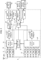
- FIG. 1 is a block diagram schematically showing an exemplary configuration of a television system including a recording and playback apparatus of the first exemplary embodiment.
- the television system includes antenna ANT, a recording and playback apparatus, program information server apparatus 3, and display 4.
- the recording and playback apparatus includes main body apparatus 1 and remote controller 2.
- Main body apparatus 1 is connected to antenna ANT.
- Main body apparatus 1 can record a plurality of programs which are broadcast from broadcast stations through broadcast waves, and play back the recorded programs.
- Main body apparatus 1 has a normal recording function and a channel recording function.
- the normal recording function is a function of recording a program being broadcast which is specified by a user or a program that is programmed to record by the user.
- the channel recording function is a function of continuously recording programs of one or more channels. Therefore, main body apparatus 1 having the channel recording function can continuously record substantially all programs that are broadcast on channels which are recording targets.
- FIG. 1 only shows components related to the present exemplary embodiment among a plurality of components included in main body apparatus 1, and omits other components.
- the other components include components (e.g., a power supply circuit) that are commonly included in a recording and playback apparatus, but description of the other components is omitted.
- Remote controller 2 can communicate with main body apparatus 1 wirelessly (e.g., Bluetooth (registered trademark)). Remote controller 2 obtains an instruction (user command) which is input by the user, and can wirelessly transmit the user command to main body apparatus 1.
- main body apparatus 1 wirelessly (e.g., Bluetooth (registered trademark)).
- Remote controller 2 obtains an instruction (user command) which is input by the user, and can wirelessly transmit the user command to main body apparatus 1.
- Program information server apparatus 3 can communicate with main body apparatus 1 through a network such as the Internet, and provide main body apparatus 1 with information related to a program being played back on main body apparatus 1.
- Display 4 is, for example, a television receiver.
- Display 4 is connected to main body apparatus 1 through an interface such as HDMI (High Definition Multimedia Interface) (registered trademark), and can display a program played back on main body apparatus 1, on screen 40.
- HDMI High Definition Multimedia Interface
- Remote controller 2 includes a motion sensor, and can detect an amount of change in posture (difference in motion) of remote controller 2 for when remote controller 2 is shaken up and down or left and right. Remote controller 2 transmits a control signal including the detected amount of change in posture, to main body apparatus 1. Main body apparatus 1 moves a pointer on screen 40 of display 4, according to the amount of change in posture transmitted from remote controller 2.
- Main body apparatus 1 of the recording and playback apparatus includes normal recorder 10, channel recorder 20, control circuit 31, Bluetooth transmitter-receiver 32, communication circuit 33, program DB (database) creating circuit 34, program playback circuit 35, UI (user interface) creating circuit 36, and screen superimposing circuit 37.
- Normal recorder 10 includes tuner 11, tuner 12, tuner 13, normal recording circuit 14, and storage apparatus 15.
- Channel recorder 20 includes tuner 21, tuner 22, tuner 23, tuner 24, tuner 25, tuner 26, channel recording circuit 27, and storage apparatus 28.
- Normal recorder 10 can record a program being broadcast which is specified by the user or a program that is programmed to record by the user.
- Channel recorder 20 can continuously record programs of one or more channels. Therefore, channel recorder 20 can continuously record substantially all programs that are broadcast on channels which are recording targets.
- Tuners 11 to 13 and tuners 21 to 26 are examples of at least one receiver. Tuners 11 to 13 and tuners 21 to 26 are connected to antenna ANT, and can receive a plurality of programs that are broadcast from broadcast stations by terrestrial broadcasting or satellite broadcasting (BS (Broadcasting Satellite) broadcasting, CS (Communications Satellite) broadcasting, or the like).
- BS Broadcasting Satellite
- CS Commonations Satellite
- Normal recording circuit 14 records a plurality of programs received by tuners 11 to 13, in storage apparatus 15.
- Channel recording circuit 27 records a plurality of programs received by tuners 21 to 26, in storage apparatus 28.
- Storage apparatus 15 and storage apparatus 28 are examples of a storage unit and may be composed of one or a plurality of hard disk drives, etc.
- Channel recorder 20 may, for example, become inactive for a period of a predetermined length of a day for maintenance of main body apparatus 1 of the recording and playback apparatus.
- Bluetooth transmitter-receiver 32 is an example of a receiver. Bluetooth transmitter-receiver 32 can receive a user command (control signal) from remote controller 2 by wirelessly communicating with remote controller 2.
- Communication circuit 33 can obtain information related to a program being played back on main body apparatus 1 from program information server apparatus 3 by communicating with program information server apparatus 3.
- the information related to a program being played back on main body apparatus 1 includes, for example, a list of scenes of the program being played back, programs similar to the program being played back, and program ranking.
- Communication circuit 33 may obtain other information such as news by communicating with program information server apparatus 3.
- Program DB creating circuit 34 can create a program database including attribute information, such as title names, recording time, and genres, and information about recording positions, of the programs recorded in storage apparatuses 15, 28.
- Program playback circuit 35 is an example of a playback unit. Program playback circuit 35 can play back one of the plurality of programs recorded in storage apparatuses 15, 28.
- UI creating circuit 36 is an example of a user interface creator.
- UI creating circuit 36 can create a plurality of user interface images, based on program database information.
- a user interface image is an image displayed on screen 40 of display 4 so that the user can select one of the plurality of programs recorded in storage apparatuses 15, 28.
- Screen superimposing circuit 37 is an example of a screen superimposer. Screen superimposing circuit 37 can generate an output video signal, based on a video signal of a program played back and a user interface image.
- Control circuit 31 is an example of a controller. Control circuit 31 can control operation of main body apparatus 1 (i.e., normal recording circuit 14, channel recording circuit 27, program playback circuit 35, and UI creating circuit 36), based on user commands.
- main body apparatus 1 i.e., normal recording circuit 14, channel recording circuit 27, program playback circuit 35, and UI creating circuit 36
- Video created by the output video signal generated by screen superimposing circuit 37 is displayed on screen 40 of display 4.
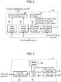
- FIG. 2 is a block diagram schematically showing an exemplary configuration of UI creating circuit 36 of the first exemplary embodiment.
- UI creating circuit 36 creates a user interface image.
- the user interface image includes a pointer having a position that changes based on an amount of change in posture of remote controller 2.
- UI creating circuit 36 includes coordinate computation circuit 51, register 52, coordinate correction circuit 53, menu creating circuit 54, pointer creating circuit 55, and UI (user interface) combining circuit 56.
- Coordinate computation circuit 51 obtains an amount of change in posture of remote controller 2 from control circuit 31. Coordinate computation circuit 51 determines virtual coordinates of a pointer in a virtual plane including a user interface image, based on the amount of change in posture of remote controller 2.
- the virtual coordinates refer to coordinates in the virtual plane.
- the virtual plane refers to a virtual plane that is set to create a user interface image in UI creating circuit 36.
- UI creating circuit 36 creates a user interface image on the virtual plane.
- Virtual coordinates of the user interface image on the virtual plane are transformed into real coordinates by UI creating circuit 36 (or screen superimposing circuit 37).
- the real coordinates refer to coordinates corresponding to screen 40 of display 4.
- screen superimposing circuit 37 can generate an output video signal by superimposing the user interface image on a video signal of a program played back.
- the virtual coordinates and the real coordinates may differ from each other or may be the same.
- Register 52 stores coordinates of predetermined regions in the virtual plane.
- the predetermined regions include a movable region, a clip region, and at least one button region, and register 52 stores coordinates of those regions.
- the movable region is a smaller region than the user interface image in the virtual plane, and represents a pointer movable range.
- the clip region is a larger region than the movable region and is provided outside the movable region in the virtual plane so as to enclose the movable region, and represents a range where movement of virtual coordinates of the pointer is limited.
- the button region is a region that is selectable by the pointer and that allows control circuit 31 to perform some sort of process (e.g., recording or playback of a program) when the region is selected.
- Initial values of virtual coordinates of pointer 111 are, for example, coordinates of a center of the movable region.
- Coordinate computation circuit 51 determines virtual coordinates of the pointer by accumulating amounts of change in posture (differences in motion) transmitted from remote controller 2.
- Coordinate correction circuit 53 corrects the virtual coordinates of the pointer based on the coordinates of the movable region, the clip region, and the button region, and thereby determines real coordinates of the pointer to be displayed on the user interface image.
- Menu creating circuit 54 creates a program selection menu, based on a program database created by program DB creating circuit 34.
- the program selection menu refers to a menu for enabling the user to select a desired program from a plurality of programs recorded by normal recorder 10 or channel recorder 20.
- Pointer creating circuit 55 creates a pointer to be superimposed on the program selection menu, based on the real coordinates of the pointer.
- UI combining circuit 56 creates (a signal representing) a user interface image by combining the program selection menu with the pointer, and sends the created (signal representing a) user interface image to screen superimposing circuit 37.
- Menu creating circuit 54 sends coordinates of an element (a program selected by the pointer, etc.) included in the created program selection menu to control circuit 31.
- Pointer creating circuit 55 sends coordinates of the created pointer to control circuit 31.
- FIG. 3 is a block diagram schematically showing an exemplary configuration of remote controller 2 of the first exemplary embodiment.
- Remote controller 2 includes control circuit 61, Bluetooth transmitter-receiver 62, motion sensor 63, motion key 64, and other keys 65.
- FIG. 3 shows components related to the present exemplary embodiment among a plurality of components included in remote controller 2, and omits other components.
- the other components include components (e.g., a power supply circuit) that are commonly included in a remote controller, but description of the other components is omitted.
- Control circuit 61 controls operation of each block of remote controller 2. In addition, when motion key 64 or other keys 65 is pressed by the user, a signal indicating that motion key 64 or other keys 65 has been pressed by the user is sent to control circuit 61 from motion key 64 or other keys 65.
- Motion sensor 63 is, for example, a gyro sensor. Motion sensor 63 operates when motion key 64 is pressed, and detects an amount of change in posture of remote controller 2 for when remote controller 2 is shaken up and down or left and right. The detected amount of change in posture is sent to Bluetooth transmitter-receiver 62 through control circuit 61.
- motion sensor 63 may detect an amount of change in posture at all times. In that case, only when motion key 64 is pressed, a detected amount of change in posture may be sent to Bluetooth transmitter-receiver 62 from control circuit 61.
- Bluetooth transmitter-receiver 62 is an example of a transmitter. Bluetooth transmitter-receiver 62 transmits a user command (control signal) including the amount of change in posture to main body apparatus 1 by communicating with main body apparatus 1.
- FIG. 4 is a top view of remote controller 2 of the first exemplary embodiment.
- FIG. 4 shows an example of a plurality of keys included in remote controller 2.
- Other keys 65 shown in FIG. 3 include, for example, cursor key 71, OK key 72, channel recording list key 73, normal recording list key 74, category list key 75, and playback menu key 76.
- cursor key 71 includes an up key, a down key, a left key, and a right key.
- FIG. 5 is a side view of remote controller 2 of the first exemplary embodiment.
- a back of remote controller 2 (a back side of a side where the plurality of keys are provided) is provided with an indentation in which a user's finger can fit. Then, motion key 64 is disposed in the indentation so that the user can easily shake remote controller 2 up and down or left and right with motion key 64 kept pressed.
- main body apparatus 1 of the recording and playback apparatus presents a plurality of program selection menus to the user.
- Main body apparatus 1 presents, for example, following three program selection menus to the user.
- a channel recording list is a program selection menu for enabling the user to select a desired program from a plurality of programs recorded by channel recorder 20.
- the channel recording list has a program table format where a plurality of programs are arranged two-dimensionally by channel and time.
- a normal recording list is a program selection menu for enabling the user to select a desired program from a plurality of programs recorded by normal recorder 10.
- the normal recording list has a format where a plurality of programs are arranged chronologically.
- a category list is a program selection menu for enabling the user to select a desired program from a plurality of programs recorded by channel recorder 20.
- the category list has a format where a plurality of programs are classified and arranged by category.
- program selection menus i.e., the channel recording list, the normal recording list, and the category list
- a plurality of recorded programs are classified and arranged by different classification methods.
- a recording and playback apparatus that can allow the user to select and play back his/her desired program from among recorded programs with a relatively small amount of time and trouble by suppressing complication of user operations.
- UI creating circuit 36 creates UI images of program selection menus with a plurality of pairs where a plurality of recorded programs are classified and arranged by a plurality of classification methods. For example, when UI creating circuit 36 creates a program selection menu for the channel recording list, UI creating circuit 36 creates a UI image where a channel and a date (or time) are paired up.
- Each program selection menu has a first program selection menu and a second program selection menu.
- the first program selection menu and the second program selection menu include a plurality of arrays of a plurality of programs classified by the same classification method.
- the channel recording list has a first program selection menu and a second program selection menu that are displayed on display 4 in a channel recording list format.
- the normal recording list has a first program selection menu and a second program selection menu that are displayed on display 4 in a normal recording list format.
- the category list has a first program selection menu and a second program selection menu that are displayed on display 4 in a category list format.
- the first program selection menu is displayed on display 4, and when a recorded program is played back, the second program selection menu is displayed on display 4 so as to be partially superimposed on video of the program being played back.
- the first program selection menu for a channel recording list has a program table format where a plurality of programs recorded by channel recorder 20 are arranged two-dimensionally with a horizontal axis being a channel and a vertical axis being time. Therefore, in the first program selection menu for a channel recording list, the plurality of programs recorded by channel recorder 20 are classified into a plurality of arrays corresponding to a plurality of channels having broadcast the programs. Then, in a display field of each channel, programs of the channel are arranged chronologically.
- the second program selection menu is a program selection menu that uses a classification method conforming to a program selection menu that is used when the program being played back is selected. For example, if it is time when a program that is selected on a first program selection menu for a channel recording list is played back, then when a user command for instructing to call a second program selection menu is input, a second program selection menu conforming to a format of the channel recording list is displayed on display 4 so as to be partially superimposed on video of the program being played back.
- a user command for instructing to call a second program selection menu is input to remote controller 2 by pressing down playback menu key 76 of remote controller 2, and transmitted to main body apparatus 1 from remote controller 2.
- the second program selection menu includes a plurality of tab menus and a plurality of detailed menus for the respective tab menus.
- control circuit 31 allows display 4 to display a plurality of tab menus.
- the plurality of tab menus are displayed, for example, along a top side, a left side, a bottom side, and a right side of screen 40 of display 4.
- control circuit 31 allows display 4 to display a detailed menu corresponding to the selected one tab menu.
- the detailed menus for the respective plurality of tab menus are also displayed, for example, along the top side, left side, bottom side, and right side of screen 40 of display 4.
- a detailed menu corresponding to the tab menu may include a plurality of icons representing a plurality of arrays (e.g., icons of a plurality of channels).
- control circuit 31 may highlight an icon of an array to which a program being played back belongs (e.g., one channel having broadcast the program being played back) in the detailed menu by a cursor or other display methods.
- a detailed menu corresponding to the tab menu may include an array to which the program being played back belongs (e.g., a plurality of programs having been broadcast on a channel having broadcast the program being played back).
- control circuit 31 may highlight the program being played back in the detailed menu by a cursor or other display methods.
- a list of representative scenes of the program being played back may be displayed on display 4.
- information on the recommended programs and the list of scenes are obtained from, for example, program information server apparatus 3.
- a first program selection menu for a normal recording list is displayed on display 4 by control circuit 31.
- a plurality of programs recorded by normal recorder 10 are classified by a plurality of predetermined tags representing program categories (e.g., genres). Then, in the first program selection menu for a normal recording list, the plurality of tags are arranged and displayed on display 4.
- a program list having a format where programs having the tag are arranged chronologically is displayed on display 4. For example, an "all" tag represents all programs recorded by normal recorder 10.
- a plurality of programs recorded by normal recorder 10 are classified into a plurality of arrays corresponding to a plurality of tags, respectively. Then, in a display field of each tag, a plurality of programs having the tag are arranged chronologically.
- a second program selection menu for the normal recording list is displayed on display 4 by control circuit 31.
- the second program selection menu for the normal recording list includes a plurality of tab menus and a plurality of detailed menus for the respective tab menus.
- a first program selection menu for a category list is displayed on display 4 by control circuit 31.
- a plurality of programs recorded by channel recorder 20 are classified into a plurality of arrays corresponding to a plurality of categories, respectively.
- only newly recorded programs may be classified into a plurality of arrays corresponding to a plurality of categories, respectively, and presented to the user.
- the first program selection menu for a category list may include a plurality of pages.
- a first page may include a history area indicating categories of programs that are often viewed by the user of the recording and playback apparatus; a ranking area indicating program ranking; and a news area indicating a list of most talked-about news.
- the program ranking and the list of most talked-about news are obtained from, for example, program information server apparatus 3.
- a second page may indicate categories of programs classified by genre.
- a third page may indicate categories of programs searched by conditions set by the user (e.g., a genre and a keyword(s)).
- a button region of each category on each page represents, for example, a thumbnail image of one program included in the category.
- Movement between the pages of the first program selection menu is performed by selecting, by a pointer, a predetermined button region on a user interface image.
- cursor key 71 of remote controller 2 may be used for movement between the pages of the first program selection menu.
- unviewed programs in the category are played back in order of oldest first by control circuit 31, according to a user's playback history.
- programs in the category are played back in order of ranking by control circuit 31.
- news category in the news area is selected by the user
- news scenes are played back in descending order of a number of broadcasts of news by control circuit 31.
- a latest program in the category is played back by control circuit 31.
- a latest program in the category is played back by control circuit 31.
- the second program selection menu for the category list includes a plurality of tab menus and a plurality of detailed menus corresponding to the respective tab menus.
- the programs are arranged in order of ranking.
- the programs are arranged in order of oldest first.
- the programs are arranged in order of newest first.
- the first program selection menu for the category list may include only a screen of one page, or may include screens of two pages, or may include screens of four or more pages.
- first program selection menus for a channel recording list and a normal recording list may include screens of two or more pages.
- control circuit 31 When, in a state in which a second program selection menu is displayed on display 4, a user command is input to instruct to display another second program selection menu that uses a different classification method than a classification method used by the second program selection menu being displayed on display 4, control circuit 31 allows display 4 to display another second program selection menu, according to the user command. Namely, control circuit 31 can move between a detailed menu for a channel recording list, a detailed menu for a category list, and a detailed menu for a normal recording list, according to a user command.
- Movement between second program selection menus is performed by selecting, by a pointer, a predetermined button region on a user interface image.
- cursor key 71 of remote controller 2 may be used for movement between pages of second program selection menus.
- control circuit 31 allows display 4 to display a first program selection menu that uses a same classification method as a classification method used by a first program selection menu or a second program selection menu that is used when the program whose playback has ended is selected.
- control circuit 31 may highlight the program whose playback has ended, in the first program selection menu displayed on display 4.
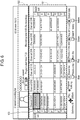
- FIG. 6 is a diagram showing an example of a screen of a channel recording list of the first exemplary embodiment.
- a drawing shown in FIG. 6 is an example of a first program selection menu for a channel recording list that is displayed on display 4 shown in FIG. 1 when channel recording list key 73 of remote controller 2 is pressed down.
- Program table area 101 has a program table format where a plurality of programs recorded by channel recorder 20 are arranged two-dimensionally with a horizontal axis being a channel and a vertical axis being time.
- the user can select a program by moving cursor 103 in program table area 101, using cursor key 71 of remote controller 2.
- description area 102 description of the program selected by cursor 103 is displayed.
- OK key 72 of remote controller 2 is pressed down, main body apparatus 1 starts playback of the program selected by cursor 103.
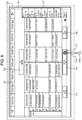
- FIG. 7 is a diagram showing an example of a motion menu of the first exemplary embodiment.
- a drawing shown in FIG. 7 is an example of a motion menu that is displayed on display 4 shown in FIG. 1 when motion key 64 of remote controller 2 is pressed down.
- the motion menu is displayed on display 4 so as to be superimposed on the first program selection menu for a channel recording list shown in FIG. 6 .
- the motion menu includes a plurality of button regions corresponding to the plurality of programs (regions set for respective display fields of the programs) in program table area 101 of FIG. 6 ; pointer 111; and button regions 112 to 117 which are links for moving to another page.
- Button region 112 is a link for moving to a page including programs in a time slot immediately before the programs displayed in program table area 101.
- Button region 114 is a link for moving to a page including programs in a time slot immediately after the programs displayed in program table area 101.
- Button region 113 and button region 115 are a link for moving to a page including channels adjacent to channels displayed in program table area 101.
- Button region 116 is a link for moving to a page including programs for a date displayed in that region.
- Button region 117 is a link for moving to a page including programs in a time slot displayed in that region.
- the user can select a program displayed in program table area 101 or a link displayed in the motion menu by moving pointer 111 by shaking remote controller 2 up and down or left and right when the motion menu exemplified in FIG. 7 is displayed on display 4.
- pointer 111 is present on a program " ⁇ " on channel CH 3 and this program is selected.
- FIG. 8 is a diagram showing examples of movable region 121 and clip region 122 of the first exemplary embodiment.
- movable region 121 is a smaller region than a user interface image in a virtual plane including the user interface image, and represents a range where pointer 111 is movable.
- Clip region 122 is a larger region than movable region 121 and provided outside movable region 121 in the virtual plane, and represents a range where movement of virtual coordinates of pointer 111 is limited.
- UI creating circuit 36 limits a position of pointer 111 displayed on display 4 within movable region 121. In addition, UI creating circuit 36 limits virtual coordinates of pointer 111 within clip region 122. Therefore, when virtual coordinates of pointer 111 are present in movable region 121, UI creating circuit 36 displays pointer 111 at a position of the virtual coordinates. In addition, when virtual coordinates of pointer 111 are present outside movable region 121 (e.g., position 111a of FIG. 8 ) in the virtual plane, UI creating circuit 36 displays pointer 111 at a position in movable region 121 closest to the virtual coordinates. Then, when virtual coordinates of pointer 111 have reached a boundary between clip region 122 and an outside of clip region 122 in the virtual plane, UI creating circuit 36 limits the virtual coordinates within clip region 122.
- UI creating circuit 36 forbids a display position of pointer 111 to move to position 111a. Furthermore, UI creating circuit 36 forbids virtual coordinates of pointer 111 having virtual coordinates of position 111a of FIG. 8 to move to position 111b.
- a user interface image includes at least one button region at a position in movable region 121 that is in contact with a boundary between movable region 121 and clip region 122, or at a position in movable region 121 where a distance from the boundary between movable region 121 and clip region 122 is less than a size of pointer 111.
- button regions 113 to 117 are in contact with the boundary between movable region 121 and clip region 122.
- pointer 111 displayed on display 4 stays at the boundary between movable region 121 and clip region 122 within movable region 121.
- pointer 111 displayed on display 4 stays on button region 114.
- pointer 111 displayed on display 4 stays on button region 114.
- main body apparatus 1 by providing clip region 122 outside movable region 121, even if remote controller 2 is moved by user's hand movement, etc., pointer 111 having been displayed on button region 113 to 117 once is less likely to be shifted from button region 113 to 117.
- button regions 113 to 117 are disposed at positions in movable region 121 that are in contact with the boundary between movable region 121 and clip region 122.
- a plurality of button regions corresponding to a plurality of programs are suppressed from being covered by button regions 113 to 117 when a motion menu is displayed so as to be superimposed on a first program selection menu for a channel recording list. Therefore, even in case where the user selects a motion menu, main information included in the first program selection menu for a channel recording list of FIG. 6 is suppressed from becoming difficult to view by button regions 113 to 117.
- FIG. 9 is a diagram describing a first correction method for virtual coordinates of pointer 111 of the first exemplary embodiment.
- button region 112 is disposed at a position in movable region 121 that has a predetermined distance from the boundary between movable region 121 and clip region 122, in order to make pointer 111 less likely to be shifted from button region 112, virtual coordinates of pointer 111 are corrected as follows.
- a user interface image includes, in movable region 121, at least one button region 112 disposed at a position having a predetermined distance from the boundary between movable region 121 and clip region 122.
- UI creating circuit 36 provides, as shown in FIG. 9 , clip section 131 to a part of a boundary of button region 112. In this case, when virtual coordinates of pointer 111 have moved from a position in button region 112 and reached clip section 131, UI creating circuit 36 limits the virtual coordinates within button region 112.
- UI creating circuit 36 forbids virtual coordinates of pointer 111 of FIG. 9 to go beyond clip section 131. Due to this, in case where the user operates main body apparatus 1 by displaying a motion menu on display 4 and moving pointer 111 on the motion menu by shaking remote controller 2 up and down or left and right, main body apparatus 1 can prevent pointer 111 from going out of button region 112 or from being shifted to button region 116 against a user's intention. In addition, it becomes easier for the user to dispose pointer 111 on button region 112 displayed on display 4. At this time, UI creating circuit 36 does not limit virtual coordinates of pointer 111 to go beyond clip section 131 in an opposite direction (from a top to a bottom of button region 112).
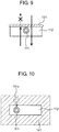
- FIG. 10 is a diagram describing a second correction method for virtual coordinates of pointer 111 of the first exemplary embodiment.
- the user interface image includes, in movable region 121, at least one button region 112.
- UI creating circuit 36 displays pointer 111 at a position in button region 112 closest to the virtual coordinates.
- pointer 111 having been disposed on button region 112 once is less likely to be shifted from button region 112.
- UI creating circuit 36 displays pointer 111 at a position of the virtual coordinates.
- main body apparatus 1 of the recording and playback apparatus operation of main body apparatus 1 of the recording and playback apparatus will be described. Note that, in the following, description will be made, as an example, of operation performed when a first program selection menu for a channel recording list is displayed on display 4. Description of operation performed when other program selection menus are displayed on display 4 is omitted, but the operation is substantially the same.
- FIG. 11 is a flowchart showing an example of a motion operation UI creation process which is performed by UI creating circuit 36 of the first exemplary embodiment.
- UI creating circuit 36 displays a program selection menu shown in FIG. 6 on display 4 (step S1).
- UI creating circuit 36 determines whether motion key 64 of remote controller 2 has been pressed (step S2).
- UI creating circuit 36 repeats a process at step S2.
- UI creating circuit 36 displays a motion menu shown in FIG. 7 on display 4 (step S3).
- Coordinate computation circuit 51 in UI creating circuit 36 resets coordinates of pointer 111 and sets the coordinates of pointer 111 to a center (substantially the center) of movable region 121 (step S4).
- Coordinate computation circuit 51 in UI creating circuit 36 receives an amount of change in posture transmitted from remote controller 2 (step S5).
- Coordinate computation circuit 51 in UI creating circuit 36 computes virtual coordinates of pointer 111, based on the amount of change in posture transmitted from remote controller 2 (step S6).
- Coordinate correction circuit 53 in UI creating circuit 36 performs a coordinate correction process (step S7).
- FIG. 12 is a flowchart showing an example of a subroutine of the coordinate correction process of the first exemplary embodiment.
- Coordinate correction circuit 53 determines whether the virtual coordinates of pointer 111 have reached a boundary between clip region 122 and an outside of clip region 122 (step S21).
- coordinate correction circuit 53 limits the virtual coordinates of pointer 111 within clip region 122 (step S22).
- coordinate correction circuit 53 determines whether the virtual coordinates of pointer 111 are present in movable region 121 (step S23).
- coordinate correction circuit 53 determines whether the virtual coordinates of pointer 111 are present on or close to a button region (e.g., any of button regions 112 to 117 and a plurality of button regions corresponding to programs which are shown in FIG. 8 ) (step S24).
- a button region e.g., any of button regions 112 to 117 and a plurality of button regions corresponding to programs which are shown in FIG. 8
- coordinate correction circuit 53 corrects the virtual coordinates of pointer 111 as described with reference to FIG. 9 or 10 (step S25).
- coordinate correction circuit 53 determines the virtual coordinates of pointer 111 as real coordinates of pointer 111 (step S26).
- coordinate correction circuit 53 determines a position in movable region 121 closest to the virtual coordinates, as real coordinates of the pointer (step S27).
- the virtual coordinates of pointer 111 in the above description may be virtual coordinates of a center of pointer 111 or may be a plurality of sets of virtual coordinates representing an outline of pointer 111.
- a region considered to be close to a button region may be appropriately set based on experiments, etc.
- coordinate correction circuit 53 may determine that the virtual coordinates of pointer 111 are present on a button region, when the virtual coordinates of the center of pointer 111 are present in the button region.
- coordinate correction circuit 53 may determine that the virtual coordinates of pointer 111 are present near a button region, when the virtual coordinates of the center of pointer 111 are not present in the button region, but a part of pointer 111 is present in the button region.
- step S8 processes at and after step S8 will be described.
- UI creating circuit 36 displays pointer 111 having the determined real coordinates, at a position of the real coordinates on screen 40 of display 4 (step S8).
- UI creating circuit 36 determines whether OK key 72 of remote controller 2 has been pressed down (step S9).
- step S9 In case where it is determined at step S9 that OK key 72 of remote controller 2 has not been pressed down (NO at step S9), UI creating circuit 36 brings processing back to step S5 and performs processes at and after step S5.
- step S9 In case where it is determined at step S9 that OK key 72 of remote controller 2 has been pressed down (YES at step S9), UI creating circuit 36 or control circuit 31 performs a process corresponding to the determined button region on screen 40 (step S10).
- step S10 the process corresponding to the determined button region on screen 40 is, for example, movement between pages on a user interface image
- UI creating circuit 36 performs the process.
- control circuit 31 performs the process.
- UI creating circuit 36 determines whether a motion operation has been turned off (step S11).
- UI creating circuit 36 ends the process.
- step S11 In case where it is determined at step S11 that the motion operation has not been turned off (NO at step S11), UI creating circuit 36 brings processing back to step S5 and performs processes at and after step S5.
- a remote control system includes a main body apparatus and a remote controller.
- the remote controller includes a motion sensor and a transmitter.
- the motion sensor detects an amount of change in posture of the remote controller.
- the transmitter transmits a control signal including the amount of change in posture to the main body apparatus.
- the main body apparatus includes a receiver, a user interface creator, and a controller.
- the receiver receives the control signal transmitted from the remote controller.
- the user interface creator creates a user interface image including a pointer having a position that changes based on the amount of change in posture.
- the controller controls operation of the main body apparatus, according to the control signal.
- the user interface creator determines virtual coordinates of the pointer in a virtual plane including the user interface image, based on the amount of change in posture.
- the user interface creator displays the pointer at a position of the virtual coordinates, the movable region being a smaller region than the user interface image.
- the user interface creator displays the pointer at a position in the movable region closest to the virtual coordinates.
- the user interface creator limits the virtual coordinates within the clip region, the clip region being a larger region than the movable region.
- an electronic device includes a user interface creator that creates a user interface image including a pointer having a position that changes based on an input signal.
- the user interface creator determines virtual coordinates of the pointer in a virtual plane including the user interface image, based on the input signal.
- the user interface creator displays the pointer at a position of the virtual coordinates, the movable region being a smaller region than the user interface image.
- the user interface creator displays the pointer at a position in the movable region closest to the virtual coordinates.
- the user interface creator limits the virtual coordinates within the clip region, the clip region being a larger region than the movable region.
- Main body apparatus 1 is an example of the main body apparatus and is also an example of the electronic device.
- Remote controller 2 is an example of the remote controller.
- Motion sensor 63 is an example of the motion sensor.
- Bluetooth transmitter-receiver 62 is an example of the transmitter.
- Bluetooth transmitter-receiver 32 is an example of the receiver.
- UI creating circuit 36 is an example of the user interface creator.
- Control circuit 31 is an example of the controller.
- Pointer 111 is an example of the pointer.
- Movable region 121 is an example of the movable region.
- Clip region 122 is an example of the clip region.
- An amount of change in posture is an example of the input signal.
- the recording and playback apparatus includes main body apparatus 1 and remote controller 2.
- Remote controller 2 includes motion sensor 63 and Bluetooth transmitter-receiver 62.
- Motion sensor 63 detects an amount of change in posture of remote controller 2.
- Bluetooth transmitter-receiver 62 transmits a control signal including the amount of change in posture to main body apparatus 1.
- Main body apparatus 1 includes Bluetooth transmitter-receiver 32, UI creating circuit 36, and control circuit 31.
- Bluetooth transmitter-receiver 32 receives the control signal transmitted from remote controller 2.
- UI creating circuit 36 creates a user interface image including pointer 111 having a position that changes based on the amount of change in posture.
- Control circuit 31 controls operation of main body apparatus 1, according to the control signal.
- UI creating circuit 36 determines virtual coordinates of pointer 111 in a virtual plane including the user interface image, based on the amount of change in posture. When the virtual coordinates of pointer 111 are present in movable region 121 in the virtual plane, UI creating circuit 36 displays pointer 111 at a position of the virtual coordinates, movable region 121 being a smaller region than the user interface image. When the virtual coordinates of pointer 111 are present outside movable region 121 in the virtual plane, UI creating circuit 36 displays pointer 111 at a position in movable region 121 closest to the virtual coordinates.
- UI creating circuit 36 limits the virtual coordinates within clip region 122, clip region 122 being a larger region than movable region 121.
- initial values of the virtual coordinates of the pointer may be coordinates of a center of the movable region.
- initial values of virtual coordinates of pointer 111 are coordinates of a center (substantially the center) of movable region 121.
- the user interface image may include at least one button region presented in the movable region and in contact with a boundary of the movable region.
- button regions 113 to 117 are examples of the button region.
- a user interface image includes button regions 113 to 117 present in movable region 121 and in contact with a boundary between movable region 121 and clip region 122.
- pointer 111 can be made less likely to be shifted from that button region.
- main information included in a user interface image can be suppressed from being covered by button regions 113 to 117 when the user displays a motion menu on display 4.
- the user interface image may include at least one button region present in the movable region and having a predetermined distance from the boundary of the movable region.
- a part of a boundary of the button region may be a clip section.
- button region 112 is an example of the button region.
- Clip section 131 is an example of the clip section.
- a user interface image includes, in movable region 121, button region 112 having a predetermined distance from the boundary between movable region 121 and clip region 122.
- a part of a boundary of button region 112 is clip section 131.
- pointer 111 can be made less likely to be shifted from button region 112. In addition, it becomes easier for the user to dispose pointer 111 on button region 112 displayed on display 4.
- the user interface image may include, in the movable region, at least one button region.
- the user interface creator may display the pointer at a position in the button region closest to the virtual coordinates.
- button region 112 is an example of the button region.
- Region 141 is an example of a region representing the predetermined distance from the button region.
- a user interface image includes button region 112 in movable region 121.
- UI creating circuit 36 displays pointer 111 at a position in button region 112 closest to the virtual coordinates.
- pointer 111 can be made less likely to be shifted from button region 112. In addition, it becomes easier for the user to dispose pointer 111 on button region 112 displayed on display 4.
- the main body apparatus may be a recording and playback apparatus that records and plays back a plurality of broadcast programs.
- main body apparatus 1 is a recording and playback apparatus that records and plays back a plurality of broadcast programs.
- the user can operate the recording and playback apparatus by shaking remote controller 2 up and down or left and right, and thus can intuitively operate the recording and playback apparatus.
- the first exemplary embodiment is described.
- the technique in the present disclosure is not limited thereto and can also be applied to an exemplary embodiment where changes, substitutions, additions, omissions, etc., are made.
- each of a user interface image, a movable region, and a clip region is rectangular, the present disclosure is not limited to this configuration in any way. They may have any other shape.
- FIGS. 6 to 8 describe a case in which UI creating circuit 36 creates a motion menu for a first program selection menu for a channel recording list, and presents the motion menu to a user.
- the motion menu is not limited to the first program selection menu for a channel recording list.
- UI creating circuit 36 may create a motion menu for a first program selection menu and a second program selection menu for each of a channel recording list, a normal recording list, and a category list.
- the first exemplary embodiment describes main body apparatus 1 and remote controller 2 of a recording and playback apparatus.
- the present disclosure is not limited to a recording and playback apparatus.
- the present disclosure is applicable to any other electronic device including a user interface creator that creates a user interface image including a pointer having a position that changes based on an amount of change in posture of a remote controller.
- a television receiver including a display that displays images or a projector may include the above-described user interface creator.
- normal recording circuit 14, channel recording circuit 27, control circuit 31, program DB creating circuit 34, program playback circuit 35, UI creating circuit 36, and screen superimposing circuit 37 are shown as individual blocks.
- control circuit 31 program DB creating circuit 34, program playback circuit 35, UI creating circuit 36, and screen superimposing circuit 37
- program DB creating circuit 34 program playback circuit 35
- UI creating circuit 36 program playback circuit 36
- screen superimposing circuit 37 is shown as individual blocks.
- the present disclosure is not limited to this configuration. A part or all of these blocks may be configured as a single block.
- these blocks may be implemented by hardware, or may be implemented by a combination of software that is created to perform these functions and a processor.
- the present disclosure is not limited to a remote control system including a main body apparatus and a remote controller.
- the present disclosure is applicable to any electronic device including a UI creating circuit that creates a user interface image including a pointer having a position that changes based on an input signal.
- a UI creating circuit that creates a user interface image including a pointer having a position that changes based on an input signal.
- the input signal is not limited to a control signal that is transmitted from the remote controller and that includes an amount of change in posture of the remote controller.
- the input signal may be arbitrary signal indicating a changing position.
- the UI creating circuit determines, based on the input signal, virtual coordinates of a pointer in a virtual plane including a user interface image.
- the UI creating circuit displays the pointer at a position of the virtual coordinates.
- the UI creating circuit displays the pointer at a position in the movable region closest to the virtual coordinates.
- the UI creating circuit limits the virtual coordinates within the clip region.
- a user can intuitively operate electronic device including the UI creating circuit that creates a user interface image including a pointer having a position that changes based on an input signal.
- the present disclosure is applicable to an electronic device that presents a user with a user interface image including a pointer that moves according to motion of a remote controller.
- the present disclosure is applicable to a television receiver, a recording and playback apparatus, etc.
Landscapes
- Engineering & Computer Science (AREA)
- Theoretical Computer Science (AREA)
- General Engineering & Computer Science (AREA)
- Human Computer Interaction (AREA)
- Physics & Mathematics (AREA)
- General Physics & Mathematics (AREA)
- Signal Processing (AREA)
- Multimedia (AREA)
- Automation & Control Theory (AREA)
- User Interface Of Digital Computer (AREA)
- Details Of Television Systems (AREA)
- Position Input By Displaying (AREA)
- Selective Calling Equipment (AREA)
Claims (5)
- Elektronische Vorrichtung umfassend einen Benutzeroberflächenersteller (36), der so konfiguriert ist, dass er ein Benutzeroberflächenbild mit einem Zeiger (111) erstellt, dessen Position basierend auf einem Eingangssignal wechselt,
wobei der Benutzeroberflächenersteller (36) so konfiguriert ist, dass er:virtuelle Koordinaten des Zeigers (111) in einer virtuellen Ebene bestimmt, die das Benutzeroberflächenbild basierend auf einem Eingangssignal enthält;wenn die virtuellen Koordinaten des Zeigers (111) in einem beweglichen Bereich (121) in der virtuellen Ebene vorhanden sind, den Zeiger (111) an einer Position der virtuellen Koordinaten anzeigt, wobei der bewegliche Bereich ein Bereich des Benutzeroberflächenbildes ist;wenn die virtuellen Koordinaten des Zeigers (111) außerhalb des beweglichen Bereichs (121) in der virtuellen Ebene vorhanden sind, den Zeiger (111) an einer Stelle im beweglichen Bereich anzeigt, der den virtuellen Koordinaten am nächsten liegt; undwenn die virtuellen Koordinaten des Zeigers (111) eine Grenze eines Clip-Bereichs (121) in der virtuellen Ebene erreicht haben, die virtuellen Koordinaten im Clip-Bereich (122) begrenzt, wobei der Clip-Bereich (122) ein größerer Bereich als der bewegliche Bereich (121) ist,wobei das Benutzeroberflächenbild einen Tastenbereich (112) enthält, der im beweglichen Bereich (121) vorhanden ist,
unddadurch gekennzeichnet ist, dass:der bewegliche Bereich ein kleinerer Bereich als das Benutzeroberflächenbild ist;der Tastenbereich (112) einen vorbestimmten Abstand von einer Grenze des beweglichen Bereichs (121) und ein Teil einer Grenze der Schaltfläche (112) ein Clip-Abschnitt (131) ist, undwenn sich die virtuellen Koordinaten des Zeigers (111) von einer Stelle im Tastenbereich (112) entfernt und den Clip-Abschnitt (131) erreicht haben, ist der Benutzeroberflächenersteller (36) so konfiguriert, dass er die virtuellen Koordinaten im Tastenbereich (112) begrenzt. - Fernsteuerungssystem umfassend: eine Hauptvorrichtung (1); und eine Fernsteuerung (2),
wobei die Fernsteuerung (2) Folgendes enthält:einen Bewegungssensor (63), der so konfiguriert ist, dass er einen Änderungsumfang in der Haltung der Fernsteuerung (2) erkennt; undeinen Transmitter (62), der so konfiguriert ist, dass er ein Steuerungssignal einschließlich des Änderungsumfangs in der Haltung an die Hauptvorrichtung (1) sendet,wobei die Hauptvorrichtung (1) eine elektronische Vorrichtung nach Anspruch 1 ist und ferner umfasst:einen Empfänger (32), der so konfiguriert ist, dass er dieses Eingangssignal, das von der Fernsteuerung (2) übertragene Signal empfängt; undeine Bedienung (31), die so konfiguriert ist, dass sie den Betrieb der Hauptvorrichtung (1) gemäß Steuerungssignal steuert. - Fernsteuerungssystem nach Anspruch 2, wobei die Ausgangswerte der virtuellen Koordinaten des Zeigers (111) Koordinaten eines Zentrums des beweglichen Bereichs (121) sind.
- Fernsteuerungssystem nach Anspruch 2, wobei die Hauptvorrichtung eine Aufnahme- und Wiedergabevorrichtung ist, die so konfiguriert ist, dass sie eine Mehrzahl von Rundfunkprogrammen aufzeichnen und wiedergeben kann.
- Fernsteuerungssystem nach Anspruch 2, das ferner eine Anzeige (4) umfasst, die so konfiguriert ist, dass sie das Benutzeroberflächenbild anzeigt.
Applications Claiming Priority (2)
| Application Number | Priority Date | Filing Date | Title |
|---|---|---|---|
| JP2015067432 | 2015-03-27 | ||
| PCT/JP2016/001497 WO2016157783A1 (ja) | 2015-03-27 | 2016-03-16 | 遠隔制御システム、および電子機器 |
Publications (3)
| Publication Number | Publication Date |
|---|---|
| EP3276473A1 EP3276473A1 (de) | 2018-01-31 |
| EP3276473A4 EP3276473A4 (de) | 2018-03-07 |
| EP3276473B1 true EP3276473B1 (de) | 2021-04-28 |
Family
ID=57005703
Family Applications (1)
| Application Number | Title | Priority Date | Filing Date |
|---|---|---|---|
| EP16771677.8A Active EP3276473B1 (de) | 2015-03-27 | 2016-03-16 | Fernsteuerungssystem und elektronische vorrichtung |
Country Status (4)
| Country | Link |
|---|---|
| US (1) | US10057619B2 (de) |
| EP (1) | EP3276473B1 (de) |
| JP (1) | JP6675062B2 (de) |
| WO (1) | WO2016157783A1 (de) |
Families Citing this family (2)
| Publication number | Priority date | Publication date | Assignee | Title |
|---|---|---|---|---|
| US10579163B2 (en) * | 2018-06-02 | 2020-03-03 | Mersive Technologies, Inc. | System and method of annotation of a shared display using a mobile device |
| KR20210102210A (ko) * | 2018-10-17 | 2021-08-19 | 메타 뷰, 인크. | 상호 작용을 위한 물리적 인터페이스로서의 모바일 플랫폼 |
Family Cites Families (10)
| Publication number | Priority date | Publication date | Assignee | Title |
|---|---|---|---|---|
| EP2219101A1 (de) | 2007-12-07 | 2010-08-18 | Sony Corporation | Steuervorrichtung, eingabevorrichtung, steuersystem, steuerverfahren und tragbare vorrichtung |
| US9100614B2 (en) * | 2008-10-31 | 2015-08-04 | Echostar Technologies L.L.C. | Graphical interface navigation based on image element proximity |
| JP2010282408A (ja) * | 2009-06-04 | 2010-12-16 | Sony Corp | 制御装置、入力装置、制御システム、ハンドヘルド装置及び制御方法 |
| KR101589179B1 (ko) * | 2009-08-31 | 2016-02-12 | 엘지전자 주식회사 | 스크린 리모컨 및 공간 리모컨에 의해 컨트롤되는 디지털 방송 수신기, 그리고 그 제어 방법 |
| JP4843703B2 (ja) | 2009-09-30 | 2011-12-21 | 株式会社東芝 | 放送受信装置 |
| KR101789619B1 (ko) * | 2010-11-22 | 2017-10-25 | 엘지전자 주식회사 | 멀티미디어 장치에서 음성과 제스쳐를 이용한 제어 방법 및 그에 따른 멀티미디어 장치 |
| CN103376919A (zh) | 2012-04-13 | 2013-10-30 | 十速兴业科技(深圳)有限公司 | 免校式光标追踪对位方法与其系统 |
| KR20130130453A (ko) | 2012-05-22 | 2013-12-02 | 엘지전자 주식회사 | 영상표시장치 및 그 동작 방법 |
| JP6036217B2 (ja) * | 2012-11-27 | 2016-11-30 | セイコーエプソン株式会社 | 表示装置、頭部装着型表示装置および表示装置の制御方法 |
| US9852764B2 (en) * | 2013-06-26 | 2017-12-26 | Touchcast LLC | System and method for providing and interacting with coordinated presentations |
-
2016
- 2016-03-16 EP EP16771677.8A patent/EP3276473B1/de active Active
- 2016-03-16 JP JP2017509246A patent/JP6675062B2/ja not_active Expired - Fee Related
- 2016-03-16 WO PCT/JP2016/001497 patent/WO2016157783A1/ja not_active Ceased
- 2016-03-16 US US15/555,562 patent/US10057619B2/en not_active Expired - Fee Related
Non-Patent Citations (1)
| Title |
|---|
| None * |
Also Published As
| Publication number | Publication date |
|---|---|
| JPWO2016157783A1 (ja) | 2018-02-01 |
| EP3276473A4 (de) | 2018-03-07 |
| JP6675062B2 (ja) | 2020-04-01 |
| WO2016157783A1 (ja) | 2016-10-06 |
| US20180054642A1 (en) | 2018-02-22 |
| US10057619B2 (en) | 2018-08-21 |
| EP3276473A1 (de) | 2018-01-31 |
Similar Documents
| Publication | Publication Date | Title |
|---|---|---|
| US11449297B2 (en) | Image display apparatus | |
| KR20150130048A (ko) | 디스플레이장치 및 그 제어방법 | |
| WO2009055544A1 (en) | Systems and methods for controlling media devices | |
| EP3203727B1 (de) | Systeme und verfahren zur navigationsprogrammauflistungen ein einer medienführungsanwendung | |
| EP2814261B1 (de) | Verfahren zum Betreiben einer Bildanzeigevorrichtung | |
| US11822776B2 (en) | Methods, systems, and media for providing media guidance with contextual controls | |
| US20100083315A1 (en) | Systems and methods for graphical control of user interface features provided by a television receiver | |
| US7810022B2 (en) | Program, information processing method, and information processing apparatus | |
| EP2329643B1 (de) | Systeme und verfahren zur grafischen steuerung der von einem tv-empfänger bereitgestellten funktionen einer benutzerschnittstelle | |
| EP3276473B1 (de) | Fernsteuerungssystem und elektronische vorrichtung | |
| US20180063474A1 (en) | Video playback device and program information display method | |
| US8209725B2 (en) | Method for providing graphical user interface for selecting broadcast program and AV apparatus therefor | |
| JP2010204870A (ja) | 入力装置 | |
| US9398324B2 (en) | Image display apparatus and operation method thereof | |
| US20180046337A1 (en) | Video playback device and program information display method | |
| JP6323761B2 (ja) | 遠隔制御システム及び電子機器 | |
| US20150293681A1 (en) | Methods, systems, and media for providing a media interface with multiple control interfaces | |
| KR100988956B1 (ko) | 디스플레이 장치 및 그 동작 방법 | |
| JP2013077116A (ja) | ネットワーク端末システム、及び端末装置 |
Legal Events
| Date | Code | Title | Description |
|---|---|---|---|
| STAA | Information on the status of an ep patent application or granted ep patent |
Free format text: STATUS: THE INTERNATIONAL PUBLICATION HAS BEEN MADE |
|
| PUAI | Public reference made under article 153(3) epc to a published international application that has entered the european phase |
Free format text: ORIGINAL CODE: 0009012 |
|
| STAA | Information on the status of an ep patent application or granted ep patent |
Free format text: STATUS: REQUEST FOR EXAMINATION WAS MADE |
|
| 17P | Request for examination filed |
Effective date: 20170904 |
|
| AK | Designated contracting states |
Kind code of ref document: A1 Designated state(s): AL AT BE BG CH CY CZ DE DK EE ES FI FR GB GR HR HU IE IS IT LI LT LU LV MC MK MT NL NO PL PT RO RS SE SI SK SM TR |
|
| AX | Request for extension of the european patent |
Extension state: BA ME |
|
| A4 | Supplementary search report drawn up and despatched |
Effective date: 20180201 |
|
| RIC1 | Information provided on ipc code assigned before grant |
Ipc: G06F 3/038 20130101ALI20180126BHEP Ipc: H04N 13/00 20180101ALI20180126BHEP Ipc: H04N 5/00 20110101ALI20180126BHEP Ipc: G06F 3/0346 20130101ALI20180126BHEP Ipc: G06F 3/0481 20130101AFI20180126BHEP |
|
| DAV | Request for validation of the european patent (deleted) | ||
| DAX | Request for extension of the european patent (deleted) | ||
| GRAP | Despatch of communication of intention to grant a patent |
Free format text: ORIGINAL CODE: EPIDOSNIGR1 |
|
| STAA | Information on the status of an ep patent application or granted ep patent |
Free format text: STATUS: GRANT OF PATENT IS INTENDED |
|
| INTG | Intention to grant announced |
Effective date: 20200515 |
|
| GRAJ | Information related to disapproval of communication of intention to grant by the applicant or resumption of examination proceedings by the epo deleted |
Free format text: ORIGINAL CODE: EPIDOSDIGR1 |
|
| STAA | Information on the status of an ep patent application or granted ep patent |
Free format text: STATUS: REQUEST FOR EXAMINATION WAS MADE |
|
| GRAP | Despatch of communication of intention to grant a patent |
Free format text: ORIGINAL CODE: EPIDOSNIGR1 |
|
| STAA | Information on the status of an ep patent application or granted ep patent |
Free format text: STATUS: GRANT OF PATENT IS INTENDED |
|
| INTC | Intention to grant announced (deleted) | ||
| INTG | Intention to grant announced |
Effective date: 20201014 |
|
| GRAS | Grant fee paid |
Free format text: ORIGINAL CODE: EPIDOSNIGR3 |
|
| GRAA | (expected) grant |
Free format text: ORIGINAL CODE: 0009210 |
|
| STAA | Information on the status of an ep patent application or granted ep patent |
Free format text: STATUS: THE PATENT HAS BEEN GRANTED |
|
| AK | Designated contracting states |
Kind code of ref document: B1 Designated state(s): AL AT BE BG CH CY CZ DE DK EE ES FI FR GB GR HR HU IE IS IT LI LT LU LV MC MK MT NL NO PL PT RO RS SE SI SK SM TR |
|
| REG | Reference to a national code |
Ref country code: GB Ref legal event code: FG4D |
|
| REG | Reference to a national code |
Ref country code: CH Ref legal event code: EP |
|
| REG | Reference to a national code |
Ref country code: AT Ref legal event code: REF Ref document number: 1387836 Country of ref document: AT Kind code of ref document: T Effective date: 20210515 |
|
| REG | Reference to a national code |
Ref country code: DE Ref legal event code: R096 Ref document number: 602016056958 Country of ref document: DE |
|
| REG | Reference to a national code |
Ref country code: IE Ref legal event code: FG4D |
|
| REG | Reference to a national code |
Ref country code: LT Ref legal event code: MG9D |
|
| REG | Reference to a national code |
Ref country code: AT Ref legal event code: MK05 Ref document number: 1387836 Country of ref document: AT Kind code of ref document: T Effective date: 20210428 |
|
| PG25 | Lapsed in a contracting state [announced via postgrant information from national office to epo] |
Ref country code: NL Free format text: LAPSE BECAUSE OF FAILURE TO SUBMIT A TRANSLATION OF THE DESCRIPTION OR TO PAY THE FEE WITHIN THE PRESCRIBED TIME-LIMIT Effective date: 20210428 Ref country code: LT Free format text: LAPSE BECAUSE OF FAILURE TO SUBMIT A TRANSLATION OF THE DESCRIPTION OR TO PAY THE FEE WITHIN THE PRESCRIBED TIME-LIMIT Effective date: 20210428 Ref country code: FI Free format text: LAPSE BECAUSE OF FAILURE TO SUBMIT A TRANSLATION OF THE DESCRIPTION OR TO PAY THE FEE WITHIN THE PRESCRIBED TIME-LIMIT Effective date: 20210428 Ref country code: HR Free format text: LAPSE BECAUSE OF FAILURE TO SUBMIT A TRANSLATION OF THE DESCRIPTION OR TO PAY THE FEE WITHIN THE PRESCRIBED TIME-LIMIT Effective date: 20210428 Ref country code: AT Free format text: LAPSE BECAUSE OF FAILURE TO SUBMIT A TRANSLATION OF THE DESCRIPTION OR TO PAY THE FEE WITHIN THE PRESCRIBED TIME-LIMIT Effective date: 20210428 Ref country code: BG Free format text: LAPSE BECAUSE OF FAILURE TO SUBMIT A TRANSLATION OF THE DESCRIPTION OR TO PAY THE FEE WITHIN THE PRESCRIBED TIME-LIMIT Effective date: 20210728 |
|
| PG25 | Lapsed in a contracting state [announced via postgrant information from national office to epo] |
Ref country code: LV Free format text: LAPSE BECAUSE OF FAILURE TO SUBMIT A TRANSLATION OF THE DESCRIPTION OR TO PAY THE FEE WITHIN THE PRESCRIBED TIME-LIMIT Effective date: 20210428 Ref country code: IS Free format text: LAPSE BECAUSE OF FAILURE TO SUBMIT A TRANSLATION OF THE DESCRIPTION OR TO PAY THE FEE WITHIN THE PRESCRIBED TIME-LIMIT Effective date: 20210828 Ref country code: GR Free format text: LAPSE BECAUSE OF FAILURE TO SUBMIT A TRANSLATION OF THE DESCRIPTION OR TO PAY THE FEE WITHIN THE PRESCRIBED TIME-LIMIT Effective date: 20210729 Ref country code: SE Free format text: LAPSE BECAUSE OF FAILURE TO SUBMIT A TRANSLATION OF THE DESCRIPTION OR TO PAY THE FEE WITHIN THE PRESCRIBED TIME-LIMIT Effective date: 20210428 Ref country code: RS Free format text: LAPSE BECAUSE OF FAILURE TO SUBMIT A TRANSLATION OF THE DESCRIPTION OR TO PAY THE FEE WITHIN THE PRESCRIBED TIME-LIMIT Effective date: 20210428 Ref country code: PT Free format text: LAPSE BECAUSE OF FAILURE TO SUBMIT A TRANSLATION OF THE DESCRIPTION OR TO PAY THE FEE WITHIN THE PRESCRIBED TIME-LIMIT Effective date: 20210830 Ref country code: NO Free format text: LAPSE BECAUSE OF FAILURE TO SUBMIT A TRANSLATION OF THE DESCRIPTION OR TO PAY THE FEE WITHIN THE PRESCRIBED TIME-LIMIT Effective date: 20210728 Ref country code: PL Free format text: LAPSE BECAUSE OF FAILURE TO SUBMIT A TRANSLATION OF THE DESCRIPTION OR TO PAY THE FEE WITHIN THE PRESCRIBED TIME-LIMIT Effective date: 20210428 |
|
| REG | Reference to a national code |
Ref country code: NL Ref legal event code: MP Effective date: 20210428 |
|
| PG25 | Lapsed in a contracting state [announced via postgrant information from national office to epo] |
Ref country code: SM Free format text: LAPSE BECAUSE OF FAILURE TO SUBMIT A TRANSLATION OF THE DESCRIPTION OR TO PAY THE FEE WITHIN THE PRESCRIBED TIME-LIMIT Effective date: 20210428 Ref country code: SK Free format text: LAPSE BECAUSE OF FAILURE TO SUBMIT A TRANSLATION OF THE DESCRIPTION OR TO PAY THE FEE WITHIN THE PRESCRIBED TIME-LIMIT Effective date: 20210428 Ref country code: EE Free format text: LAPSE BECAUSE OF FAILURE TO SUBMIT A TRANSLATION OF THE DESCRIPTION OR TO PAY THE FEE WITHIN THE PRESCRIBED TIME-LIMIT Effective date: 20210428 Ref country code: CZ Free format text: LAPSE BECAUSE OF FAILURE TO SUBMIT A TRANSLATION OF THE DESCRIPTION OR TO PAY THE FEE WITHIN THE PRESCRIBED TIME-LIMIT Effective date: 20210428 Ref country code: DK Free format text: LAPSE BECAUSE OF FAILURE TO SUBMIT A TRANSLATION OF THE DESCRIPTION OR TO PAY THE FEE WITHIN THE PRESCRIBED TIME-LIMIT Effective date: 20210428 Ref country code: RO Free format text: LAPSE BECAUSE OF FAILURE TO SUBMIT A TRANSLATION OF THE DESCRIPTION OR TO PAY THE FEE WITHIN THE PRESCRIBED TIME-LIMIT Effective date: 20210428 Ref country code: ES Free format text: LAPSE BECAUSE OF FAILURE TO SUBMIT A TRANSLATION OF THE DESCRIPTION OR TO PAY THE FEE WITHIN THE PRESCRIBED TIME-LIMIT Effective date: 20210428 |
|
| REG | Reference to a national code |
Ref country code: DE Ref legal event code: R097 Ref document number: 602016056958 Country of ref document: DE |
|
| PLBE | No opposition filed within time limit |
Free format text: ORIGINAL CODE: 0009261 |
|
| STAA | Information on the status of an ep patent application or granted ep patent |
Free format text: STATUS: NO OPPOSITION FILED WITHIN TIME LIMIT |
|
| 26N | No opposition filed |
Effective date: 20220131 |
|
| PGFP | Annual fee paid to national office [announced via postgrant information from national office to epo] |
Ref country code: GB Payment date: 20220321 Year of fee payment: 7 |
|
| PG25 | Lapsed in a contracting state [announced via postgrant information from national office to epo] |
Ref country code: IS Free format text: LAPSE BECAUSE OF FAILURE TO SUBMIT A TRANSLATION OF THE DESCRIPTION OR TO PAY THE FEE WITHIN THE PRESCRIBED TIME-LIMIT Effective date: 20210828 Ref country code: AL Free format text: LAPSE BECAUSE OF FAILURE TO SUBMIT A TRANSLATION OF THE DESCRIPTION OR TO PAY THE FEE WITHIN THE PRESCRIBED TIME-LIMIT Effective date: 20210428 |
|
| PG25 | Lapsed in a contracting state [announced via postgrant information from national office to epo] |
Ref country code: IT Free format text: LAPSE BECAUSE OF FAILURE TO SUBMIT A TRANSLATION OF THE DESCRIPTION OR TO PAY THE FEE WITHIN THE PRESCRIBED TIME-LIMIT Effective date: 20210428 |
|
| PGFP | Annual fee paid to national office [announced via postgrant information from national office to epo] |
Ref country code: FR Payment date: 20220421 Year of fee payment: 8 |
|
| PG25 | Lapsed in a contracting state [announced via postgrant information from national office to epo] |
Ref country code: MC Free format text: LAPSE BECAUSE OF FAILURE TO SUBMIT A TRANSLATION OF THE DESCRIPTION OR TO PAY THE FEE WITHIN THE PRESCRIBED TIME-LIMIT Effective date: 20210428 |
|
| REG | Reference to a national code |
Ref country code: CH Ref legal event code: PL |
|
| REG | Reference to a national code |
Ref country code: BE Ref legal event code: MM Effective date: 20220331 |
|
| PG25 | Lapsed in a contracting state [announced via postgrant information from national office to epo] |
Ref country code: LU Free format text: LAPSE BECAUSE OF NON-PAYMENT OF DUE FEES Effective date: 20220316 Ref country code: LI Free format text: LAPSE BECAUSE OF NON-PAYMENT OF DUE FEES Effective date: 20220331 Ref country code: IE Free format text: LAPSE BECAUSE OF NON-PAYMENT OF DUE FEES Effective date: 20220316 Ref country code: CH Free format text: LAPSE BECAUSE OF NON-PAYMENT OF DUE FEES Effective date: 20220331 |
|
| PG25 | Lapsed in a contracting state [announced via postgrant information from national office to epo] |
Ref country code: BE Free format text: LAPSE BECAUSE OF NON-PAYMENT OF DUE FEES Effective date: 20220331 |
|
| PGFP | Annual fee paid to national office [announced via postgrant information from national office to epo] |
Ref country code: DE Payment date: 20220609 Year of fee payment: 8 |
|
| GBPC | Gb: european patent ceased through non-payment of renewal fee |
Effective date: 20230316 |
|
| PG25 | Lapsed in a contracting state [announced via postgrant information from national office to epo] |
Ref country code: GB Free format text: LAPSE BECAUSE OF NON-PAYMENT OF DUE FEES Effective date: 20230316 |
|
| PG25 | Lapsed in a contracting state [announced via postgrant information from national office to epo] |
Ref country code: GB Free format text: LAPSE BECAUSE OF NON-PAYMENT OF DUE FEES Effective date: 20230316 |
|
| PG25 | Lapsed in a contracting state [announced via postgrant information from national office to epo] |
Ref country code: HU Free format text: LAPSE BECAUSE OF FAILURE TO SUBMIT A TRANSLATION OF THE DESCRIPTION OR TO PAY THE FEE WITHIN THE PRESCRIBED TIME-LIMIT; INVALID AB INITIO Effective date: 20160316 |
|
| PG25 | Lapsed in a contracting state [announced via postgrant information from national office to epo] |
Ref country code: MK Free format text: LAPSE BECAUSE OF FAILURE TO SUBMIT A TRANSLATION OF THE DESCRIPTION OR TO PAY THE FEE WITHIN THE PRESCRIBED TIME-LIMIT Effective date: 20210428 Ref country code: CY Free format text: LAPSE BECAUSE OF FAILURE TO SUBMIT A TRANSLATION OF THE DESCRIPTION OR TO PAY THE FEE WITHIN THE PRESCRIBED TIME-LIMIT Effective date: 20210428 |
|
| PG25 | Lapsed in a contracting state [announced via postgrant information from national office to epo] |
Ref country code: MT Free format text: LAPSE BECAUSE OF FAILURE TO SUBMIT A TRANSLATION OF THE DESCRIPTION OR TO PAY THE FEE WITHIN THE PRESCRIBED TIME-LIMIT Effective date: 20210428 |
|
| REG | Reference to a national code |
Ref country code: DE Ref legal event code: R119 Ref document number: 602016056958 Country of ref document: DE |
|
| PG25 | Lapsed in a contracting state [announced via postgrant information from national office to epo] |
Ref country code: DE Free format text: LAPSE BECAUSE OF NON-PAYMENT OF DUE FEES Effective date: 20241001 |
|
| PG25 | Lapsed in a contracting state [announced via postgrant information from national office to epo] |
Ref country code: FR Free format text: LAPSE BECAUSE OF NON-PAYMENT OF DUE FEES Effective date: 20240331 |
|
| PG25 | Lapsed in a contracting state [announced via postgrant information from national office to epo] |
Ref country code: FR Free format text: LAPSE BECAUSE OF NON-PAYMENT OF DUE FEES Effective date: 20240331 Ref country code: DE Free format text: LAPSE BECAUSE OF NON-PAYMENT OF DUE FEES Effective date: 20241001 |
|
| PG25 | Lapsed in a contracting state [announced via postgrant information from national office to epo] |
Ref country code: TR Free format text: LAPSE BECAUSE OF FAILURE TO SUBMIT A TRANSLATION OF THE DESCRIPTION OR TO PAY THE FEE WITHIN THE PRESCRIBED TIME-LIMIT Effective date: 20210428 |