EP3276471A1 - Touchscreen defroster - Google Patents
Touchscreen defroster Download PDFInfo
- Publication number
- EP3276471A1 EP3276471A1 EP17183086.2A EP17183086A EP3276471A1 EP 3276471 A1 EP3276471 A1 EP 3276471A1 EP 17183086 A EP17183086 A EP 17183086A EP 3276471 A1 EP3276471 A1 EP 3276471A1
- Authority
- EP
- European Patent Office
- Prior art keywords
- coating
- base
- signal
- touchscreen
- base material
- Prior art date
- Legal status (The legal status is an assumption and is not a legal conclusion. Google has not performed a legal analysis and makes no representation as to the accuracy of the status listed.)
- Granted
Links
Images
Classifications
-
- G—PHYSICS
- G06—COMPUTING OR CALCULATING; COUNTING
- G06F—ELECTRIC DIGITAL DATA PROCESSING
- G06F3/00—Input arrangements for transferring data to be processed into a form capable of being handled by the computer; Output arrangements for transferring data from processing unit to output unit, e.g. interface arrangements
- G06F3/01—Input arrangements or combined input and output arrangements for interaction between user and computer
- G06F3/03—Arrangements for converting the position or the displacement of a member into a coded form
- G06F3/041—Digitisers, e.g. for touch screens or touch pads, characterised by the transducing means
- G06F3/0416—Control or interface arrangements specially adapted for digitisers
-
- B—PERFORMING OPERATIONS; TRANSPORTING
- B05—SPRAYING OR ATOMISING IN GENERAL; APPLYING FLUENT MATERIALS TO SURFACES, IN GENERAL
- B05D—PROCESSES FOR APPLYING FLUENT MATERIALS TO SURFACES, IN GENERAL
- B05D7/00—Processes, other than flocking, specially adapted for applying liquids or other fluent materials to particular surfaces or for applying particular liquids or other fluent materials
- B05D7/50—Multilayers
-
- G—PHYSICS
- G06—COMPUTING OR CALCULATING; COUNTING
- G06F—ELECTRIC DIGITAL DATA PROCESSING
- G06F1/00—Details not covered by groups G06F3/00 - G06F13/00 and G06F21/00
- G06F1/16—Constructional details or arrangements
- G06F1/1601—Constructional details related to the housing of computer displays, e.g. of CRT monitors, of flat displays
-
- G—PHYSICS
- G06—COMPUTING OR CALCULATING; COUNTING
- G06F—ELECTRIC DIGITAL DATA PROCESSING
- G06F3/00—Input arrangements for transferring data to be processed into a form capable of being handled by the computer; Output arrangements for transferring data from processing unit to output unit, e.g. interface arrangements
- G06F3/01—Input arrangements or combined input and output arrangements for interaction between user and computer
- G06F3/03—Arrangements for converting the position or the displacement of a member into a coded form
- G06F3/041—Digitisers, e.g. for touch screens or touch pads, characterised by the transducing means
- G06F3/0412—Digitisers structurally integrated in a display
-
- G—PHYSICS
- G06—COMPUTING OR CALCULATING; COUNTING
- G06F—ELECTRIC DIGITAL DATA PROCESSING
- G06F3/00—Input arrangements for transferring data to be processed into a form capable of being handled by the computer; Output arrangements for transferring data from processing unit to output unit, e.g. interface arrangements
- G06F3/01—Input arrangements or combined input and output arrangements for interaction between user and computer
- G06F3/03—Arrangements for converting the position or the displacement of a member into a coded form
- G06F3/041—Digitisers, e.g. for touch screens or touch pads, characterised by the transducing means
- G06F3/044—Digitisers, e.g. for touch screens or touch pads, characterised by the transducing means by capacitive means
Definitions
- Service terminals have become ubiquitous within the retail environment.
- service terminals can include self-service terminals (SST) and cashier service terminals.
- SST self-service terminals
- cashier service terminals Service terminals allow customers to quickly checkout by allowing the customer or a cashier to scan items having a barcode. The items are scanned by moving items quickly over a scanner.
- the touchscreen can include a base material, a first coating, and a controller.
- the first coating can be applied to the base material.
- the first coating can be configured to generate an input signal.
- the controller can be configured to apply a base signal to the first coating, and filter the input signal from a combined signal.
- the combined signal can include the input signal and the base signal.
- a touchscreen including a base material; a first coating applied to the base material, the first coating configured to generate an input signal; and a controller configured to: apply a base signal to the first coating, and filter the input signal from a combined signal, the combined signal including the input signal and the base signal.
- the first coating may be indium tin oxide.
- the touchscreen may further include a display, the base material located proximate the display.
- the display and the base material may form a channel
- the touchscreen may further include a fan arranged to move air within the channel.
- the touchscreen may further include a second coating applied to the base material.
- the first coating may be applied to a first side of the base material and the second coating is applied to a second side of the base material.
- the first coating and the second coating may each be applied to a first side of the base material.
- the base material may be glass.
- applying the base signal may include the controller configured to adjust the base signal based on an ambient temperature.
- a touchscreen including a glass base having a surface area; a first coating applied to the glass base, the first coating configured to generate an input signal in response to a user touching the glass base; and a controller configured to: apply a base signal to the first coating, the base signal being proportional to the surface area of the glass base, receive a combined signal, the combined signal including the input signal and the base signal, and filter the input signal from the combined signal.
- the first coating may be indium tin oxide.
- the touchscreen may further include a display, the glass base located proximate the display.
- the display and the glass base may form a channel, the touchscreen further comprising a fan arranged to move air within the channel.
- the touchscreen may further include a second coating applied to the glass base.
- the first coating may be applied to a first side of the glass base and the second coating is applied to a second side of the glass base.
- the first coating and the second coating may each be applied to a first side of the glass base.
- applying the base signal may include the controller configured to adjust the base signal based on an ambient temperature.
- a service terminal including a display; a base, the base located parallel to and proximate the display; a first coating applied to the base, the first coating configured to generate a capacitance change in response to a user touching the base at an input location; a second coating applied to the base and separated from the first coating by an insulator; and a controller configured to: apply a base signal to the first coating and the second coating, determine the capacitance change in response to the user touching the base, correlate the capacitance change and the base signal into an input signal corresponding to the input location.
- the first coating and the second coating may each be each indium time oxide.
- the base may be the insulator and the first coating may be applied to a first side of the base and the second coating may be applied to a second side of the base.
- Service terminals can be located in a variety of environments.
- service terminals can be located inside or outside buildings.
- a portion of a service terminal can be located inside a building and another portion of the service terminal can be located inside the building.
- a service terminal such as an automated teller machine, can have a touchscreen and media accepter/dispenser that is located outside a bank and the media storage or other valuable storage can be located inside the bank.
- frost Due to the temperature difference between the inside of the service terminal and outside of the building, frost can form on the touchscreen.
- air inside the service terminal can be warm and humid.
- the humidity in the air can condense and form frost.
- a base material of a touchscreen can include a coating.
- a base current can be applied to the coating. As the base current flows through the coating, the coating and a portion of the base material can heat up. The heating of the coating and the portion of the base material can work to evaporate any condensation or melt any frost that may form on touchscreen.
- a controller can apply the base current.
- the controller can receive a signal that can include input signals from the base as the user touches the base material and the base current.
- the controller can filter received signal into the input signals and the base current. By filtering the base current from the received signal, the controller can determine values for the input signals and determine where a user is touching the touchscreen.
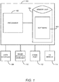
- FIG. 1 is a block diagram of a service terminal 100 according to an example embodiment.
- the service terminal 100 can include a processor 102 and a memory unit 104.
- the memory unit 104 may include software 106. While executing on the processor 102, the software 104 may perform processes for executing operating the service terminal 100, including, for example, one or more stages included in method 300 described below with respect to FIG. 3 .
- the self-service terminal 100 may also include a user interface 108.
- the user interface 108 may include any number of devices that allow a user to interface with the self-service terminal 100.
- Non-limiting examples of the user interface 112 include a keypad, a microphone, a speaker, a touchscreen, etc.
- the self-service terminal 100 may also include a media acceptor/dispenser 110.
- the media acceptor/dispenser 100 may include any number of devices that allow a user to insert media into or receive media from the self-service terminal 100.
- the media acceptor/dispenser 110 may be a single unit that performs both functions of accepting and dispensing media or the media acceptor/dispenser 110 may be multiple units. Each of the multiple units may perform a single function. For example, a first unit may accept media and a second unit may dispense media.
- the self-service terminal 100 may also include a communications port 112.
- the communications port 112 may allow the self-service terminal 100 to communicate with information systems, remote servers, other self-service terminals, etc.
- Non-limiting examples of the communications port 112 include, Ethernet cards (wireless or wired), Bluetooth® transmitters and receivers, near-field communications modules, etc.
- the self-service terminal 100 may also include an input/output (I/O) device 114.
- the I/O device 114 may allow the self-service terminal 100 to receive and output information.
- Non-limiting examples of the I/O device 114 include, a camera (still or video), a printer, a scanner, a touchscreen, etc.
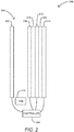
- FIG. 2 shows a touchscreen 200 according to an example embodiment.
- the touchscreen 200 can be a component of the service terminal 100.
- the touchscreen 200 can be a component of the user interface 108 or the I/O module 114.
- the touchscreen 200 can include a display 202, base 204, and a controller 206.
- the display 202 and the base 204 can be spaced a distance apart to form a channel 208.
- a fan 210 can be located proximate the channel 208 and arranged to direct air through the channel 208. The airflow can be used to assist in cooling the display and remove moisture that may accumulate proximate the display 202 and the base 204.
- the distance between the display 202 and the base 204 can range from about 5 mm to about 15 mm.
- the base 204 can act as a protector of the display 202.
- the base 204 can be a piece of glass with which a user can touch and interact.
- the base 204 can be arranged parallel to the display 202 or at an angle.
- the base 204 can include a first coating 212, a second coating 214, and a third coating 216 (collectively the coatings).
- the coatings can be any electrically conductive material.
- the coatings can be indium tin oxide.
- any of the coatings can be located on any side of the base 204.
- any of the coatings can be located on the same side of the base 204.
- the first coating 212 and the third coating 216 can located on a first side of the base 204 and separated by an insulator 218.
- the insulator 218 can allow different currents to be applied to the different coatings. For example, a first current can be applied to the third coating 216 and a second current can be applied to the first coating 212.
- one of the coatings can generate a signal that corresponds to an input from a user.
- the touchscreen 200 can be a capacitance touchscreen and when a user touches the base 204 a capacitance change.
- the capacitance change can be detected by the controller 206.
- the controller 206 also can generate and receive other signals.
- the controller 206 can be in electrical communication with the display 202, the first coating 212, the second coating 214, and the third coating 216.
- the controller 206 can receive the input signal, registered as a capacitance change detected by a voltage or current change.
- the controller 206 can also generate a voltage or current that can be transmitted to one of the coatings that can be used to detect the capacitance change.
- signal, current, and voltage can be used interchangeable.
- the controller 206 can generate or receive signals. Those signals can be in the form of a voltage or a current. A current can be related to a voltage or resistance via Ohm's law.
- the base current that is needed to heat the base to remove or hinder the formation of frost on the touchscreen 206 can vary.
- the amount of heat needed can vary depending on the ambient temperature.
- the base current can vary depending on the ambient temperature.
- the controller 206 can receive ambient temperature readings using the I/O module 114.
- the I/O module 114 can include thermal couples or other temperature sensors.
- the base current can also be related to the size of the base 204. For example, a larger base may require a larger base current than a smaller base.
- the controller 206 can be the processor 102 or a stand along component.
- the controller 206 can be the processor 102 and the method 300 can be carried out via software 106.
- the controller 206 can be a standalone processor and firmware used to execute the method 300.
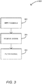
- FIG. 3 shows a method 300 for defrosting a touchscreen, such as the touchscreen 200, according to an example embodiment.
- the method 300 can start at stage 302 were a base signal can be applied to a first coating (e.g., the first coating 212).
- the base signal can also be applied to a second coating (e.g., the second coating 214 or the third coating 216).
- a first signal could be sent to a first coating and a s second signal can be sent to a second coating.
- the first signal can be the base signal used to heat the touchscreen.
- the second signal can be used to measure a capacitance change when a user touches the touchscreen.
- the first signal and the second signal can be applied to a signal coating.
- a first signal can be the base signal and the second signal can be used to measure a capacitance change when a user touches the touchscreen.
- the various signals can be modulated by the controller reduce interference between the signals.
- a signal can be received.
- a signal that represents a capacitance change can be received at the controller.
- the signal can be in the form of a combined signal or multiple signals.
- a combined signal that includes the base signal and the signal corresponding to a capacitance change can be received at the controller.
- the received signal can be a modulated signal.
- the method 300 can proceed to stage 306 where the received signal can be filtered.
- the controller can demodulate a modulated signal.
- filters such as low-pass, high-pass, and band-pass filters can be used to filter the received signal into the base signal and an input signal. The filtering of the signal can allow the controller to correlate the input signal to an input location.
- the input location can correspond to a location on the touchscreen that was touched by a user.
Landscapes
- Engineering & Computer Science (AREA)
- General Engineering & Computer Science (AREA)
- Theoretical Computer Science (AREA)
- Human Computer Interaction (AREA)
- Physics & Mathematics (AREA)
- General Physics & Mathematics (AREA)
- Computer Hardware Design (AREA)
- Life Sciences & Earth Sciences (AREA)
- Wood Science & Technology (AREA)
- Position Input By Displaying (AREA)
- User Interface Of Digital Computer (AREA)
Abstract
Description
- Service terminals have become ubiquitous within the retail environment. At the retail level, service terminals can include self-service terminals (SST) and cashier service terminals. Service terminals allow customers to quickly checkout by allowing the customer or a cashier to scan items having a barcode. The items are scanned by moving items quickly over a scanner.
- Disclosed is a touchscreen. The touchscreen can include a base material, a first coating, and a controller. The first coating can be applied to the base material. The first coating can be configured to generate an input signal. The controller can be configured to apply a base signal to the first coating, and filter the input signal from a combined signal. The combined signal can include the input signal and the base signal.
- According to a first aspect of the present invention, there is provided a touchscreen including a base material; a first coating applied to the base material, the first coating configured to generate an input signal; and a controller configured to: apply a base signal to the first coating, and filter the input signal from a combined signal, the combined signal including the input signal and the base signal.
- Optionally, the first coating may be indium tin oxide.
- Optionally, the touchscreen may further include a display, the base material located proximate the display.
- Optionally, the display and the base material may form a channel, the touchscreen may further include a fan arranged to move air within the channel.
- Optionally, the touchscreen may further include a second coating applied to the base material.
- Optionally, the first coating may be applied to a first side of the base material and the second coating is applied to a second side of the base material.
- Optionally, the first coating and the second coating may each be applied to a first side of the base material.
- Optionally, the base material may be glass.
- Optionally, applying the base signal may include the controller configured to adjust the base signal based on an ambient temperature.
- According to a second aspect of the present invention, there is provided a touchscreen including a glass base having a surface area; a first coating applied to the glass base, the first coating configured to generate an input signal in response to a user touching the glass base; and a controller configured to: apply a base signal to the first coating, the base signal being proportional to the surface area of the glass base, receive a combined signal, the combined signal including the input signal and the base signal, and filter the input signal from the combined signal.
- Optionally, the first coating may be indium tin oxide.
- Optionally, the touchscreen may further include a display, the glass base located proximate the display.
- Optionally, the display and the glass base may form a channel, the touchscreen further comprising a fan arranged to move air within the channel.
- Optionally, the touchscreen may further include a second coating applied to the glass base.
- Optionally, the first coating may be applied to a first side of the glass base and the second coating is applied to a second side of the glass base.
- Optionally, the first coating and the second coating may each be applied to a first side of the glass base.
- Optionally, applying the base signal may include the controller configured to adjust the base signal based on an ambient temperature.
- According to a third aspect of the present invention, there is provided a service terminal including a display; a base, the base located parallel to and proximate the display; a first coating applied to the base, the first coating configured to generate a capacitance change in response to a user touching the base at an input location; a second coating applied to the base and separated from the first coating by an insulator; and a controller configured to: apply a base signal to the first coating and the second coating, determine the capacitance change in response to the user touching the base, correlate the capacitance change and the base signal into an input signal corresponding to the input location.
- Optionally, the first coating and the second coating may each be each indium time oxide.
- Optionally, the base may be the insulator and the first coating may be applied to a first side of the base and the second coating may be applied to a second side of the base.
- These and other aspects of the present invention will be apparent from the following specific description, given by way of example, with reference to the accompanying drawings, in which:
- The above-mentioned and other features and advantages disclosed herein, and the manner of attaining them, will become more apparent and the disclosure itself will be better understood by reference to the following description of embodiments taken in conjunction with the accompanying drawings, wherein:
-
FIG. 1 shows a perspective view of a service terminal according to an example embodiment; -
FIG 2 shows a touchscreen according to an example embodiment; and -
FIG. 3 shows an example method according to an example embodiment. - Corresponding reference characters indicate corresponding parts throughout the several views. The exemplifications set out herein illustrate embodiments, and such examples are not to be construed as limiting the scope of the appended claims any manner.
- The following detailed description refers to the accompanying drawings. Wherever possible, the same reference numbers are used in the drawings and the following description to refer to the same or similar elements. While embodiments and examples are described, modifications, adaptations, and other implementations are possible. For example, substitutions, additions, or modifications may be made to the elements and stages illustrated in the drawings, and the systems and methods described herein may be modified by substituting, reordering, or adding stages to the disclosed methods or elements to the discloses systems. Accordingly, the following detailed description does not limit the disclosure. Instead, the proper scope of any invention disclosed herein is defined by the appended claims.
- Service terminals can be located in a variety of environments. For example, service terminals can be located inside or outside buildings. In addition, a portion of a service terminal can be located inside a building and another portion of the service terminal can be located inside the building. For instance, a service terminal, such as an automated teller machine, can have a touchscreen and media accepter/dispenser that is located outside a bank and the media storage or other valuable storage can be located inside the bank.
- Due to the temperature difference between the inside of the service terminal and outside of the building, frost can form on the touchscreen. For example, air inside the service terminal can be warm and humid. As that air contacts components of the touchscreen that are cool due to being exposed to outside ambient air, the humidity in the air can condense and form frost.
- To combat the frost, a base material of a touchscreen can include a coating. A base current can be applied to the coating. As the base current flows through the coating, the coating and a portion of the base material can heat up. The heating of the coating and the portion of the base material can work to evaporate any condensation or melt any frost that may form on touchscreen.
- During operation of the service terminal, a controller can apply the base current. In addition, the controller can receive a signal that can include input signals from the base as the user touches the base material and the base current. The controller can filter received signal into the input signals and the base current. By filtering the base current from the received signal, the controller can determine values for the input signals and determine where a user is touching the touchscreen.
- Turning now to the figures,
FIG. 1 is a block diagram of aservice terminal 100 according to an example embodiment. Theservice terminal 100 can include aprocessor 102 and amemory unit 104. Thememory unit 104 may includesoftware 106. While executing on theprocessor 102, thesoftware 104 may perform processes for executing operating theservice terminal 100, including, for example, one or more stages included inmethod 300 described below with respect toFIG. 3 . - The self-
service terminal 100 may also include auser interface 108. Theuser interface 108 may include any number of devices that allow a user to interface with the self-service terminal 100. Non-limiting examples of theuser interface 112 include a keypad, a microphone, a speaker, a touchscreen, etc. - The self-
service terminal 100 may also include a media acceptor/dispenser 110. The media acceptor/dispenser 100 may include any number of devices that allow a user to insert media into or receive media from the self-service terminal 100. The media acceptor/dispenser 110 may be a single unit that performs both functions of accepting and dispensing media or the media acceptor/dispenser 110 may be multiple units. Each of the multiple units may perform a single function. For example, a first unit may accept media and a second unit may dispense media. - The self-
service terminal 100 may also include acommunications port 112. Thecommunications port 112 may allow the self-service terminal 100 to communicate with information systems, remote servers, other self-service terminals, etc. Non-limiting examples of thecommunications port 112 include, Ethernet cards (wireless or wired), Bluetooth® transmitters and receivers, near-field communications modules, etc. - The self-
service terminal 100 may also include an input/output (I/O)device 114. The I/O device 114 may allow the self-service terminal 100 to receive and output information. Non-limiting examples of the I/O device 114 include, a camera (still or video), a printer, a scanner, a touchscreen, etc. -
FIG. 2 shows atouchscreen 200 according to an example embodiment. Thetouchscreen 200 can be a component of theservice terminal 100. For example, thetouchscreen 200 can be a component of theuser interface 108 or the I/O module 114. - The
touchscreen 200 can include adisplay 202,base 204, and acontroller 206. Thedisplay 202 and the base 204 can be spaced a distance apart to form achannel 208. Afan 210 can be located proximate thechannel 208 and arranged to direct air through thechannel 208. The airflow can be used to assist in cooling the display and remove moisture that may accumulate proximate thedisplay 202 and thebase 204. The distance between thedisplay 202 and the base 204 can range from about 5 mm to about 15 mm. - The base 204 can act as a protector of the
display 202. For example, the base 204 can be a piece of glass with which a user can touch and interact. The base 204 can be arranged parallel to thedisplay 202 or at an angle. - The base 204 can include a
first coating 212, asecond coating 214, and a third coating 216 (collectively the coatings). The coatings can be any electrically conductive material. For example, the coatings can be indium tin oxide. In addition, any of the coatings can be located on any side of thebase 204. In addition, any of the coatings can be located on the same side of thebase 204. For example, as shown inFIG. 2 , thefirst coating 212 and thethird coating 216 can located on a first side of thebase 204 and separated by aninsulator 218. Theinsulator 218 can allow different currents to be applied to the different coatings. For example, a first current can be applied to thethird coating 216 and a second current can be applied to thefirst coating 212. - During use, one of the coatings can generate a signal that corresponds to an input from a user. For example, the
touchscreen 200 can be a capacitance touchscreen and when a user touches the base 204 a capacitance change. The capacitance change can be detected by thecontroller 206. - The
controller 206 also can generate and receive other signals. For example, thecontroller 206 can be in electrical communication with thedisplay 202, thefirst coating 212, thesecond coating 214, and thethird coating 216. Thecontroller 206 can receive the input signal, registered as a capacitance change detected by a voltage or current change. Thecontroller 206 can also generate a voltage or current that can be transmitted to one of the coatings that can be used to detect the capacitance change. - As used herein, signal, current, and voltage can be used interchangeable. For example, the
controller 206 can generate or receive signals. Those signals can be in the form of a voltage or a current. A current can be related to a voltage or resistance via Ohm's law. - The base current that is needed to heat the base to remove or hinder the formation of frost on the
touchscreen 206 can vary. For example, the amount of heat needed can vary depending on the ambient temperature. As a result, the base current can vary depending on the ambient temperature. Thecontroller 206 can receive ambient temperature readings using the I/O module 114. For instance, the I/O module 114 can include thermal couples or other temperature sensors. The base current can also be related to the size of thebase 204. For example, a larger base may require a larger base current than a smaller base. - The
controller 206 can be theprocessor 102 or a stand along component. For example, thecontroller 206 can be theprocessor 102 and themethod 300 can be carried out viasoftware 106. In addition, thecontroller 206 can be a standalone processor and firmware used to execute themethod 300. -
FIG. 3 shows amethod 300 for defrosting a touchscreen, such as thetouchscreen 200, according to an example embodiment. Themethod 300 can start atstage 302 were a base signal can be applied to a first coating (e.g., the first coating 212). The base signal can also be applied to a second coating (e.g., thesecond coating 214 or the third coating 216). - In
stage 302 more than one signal can be applied. For example, a first signal could be sent to a first coating and a s second signal can be sent to a second coating. The first signal can be the base signal used to heat the touchscreen. The second signal can be used to measure a capacitance change when a user touches the touchscreen. - The first signal and the second signal can be applied to a signal coating. For example, a first signal can be the base signal and the second signal can be used to measure a capacitance change when a user touches the touchscreen. To apply more than one signal to a single conductive coating, the various signals can be modulated by the controller reduce interference between the signals.
- From
stage 302, themethod 300 can proceed to stage 304 where a signal can be received. For example, a signal that represents a capacitance change can be received at the controller. The signal can be in the form of a combined signal or multiple signals. For example, a combined signal that includes the base signal and the signal corresponding to a capacitance change can be received at the controller. The received signal can be a modulated signal. - From
stage 304, themethod 300 can proceed to stage 306 where the received signal can be filtered. For example, the controller can demodulate a modulated signal. In addition, filters such as low-pass, high-pass, and band-pass filters can be used to filter the received signal into the base signal and an input signal. The filtering of the signal can allow the controller to correlate the input signal to an input location. The input location can correspond to a location on the touchscreen that was touched by a user. - In the foregoing description of the embodiments, various features are grouped together in a single embodiment for the purpose of streamlining the disclosure. This method of disclosure is not to be interpreted as reflecting that the claimed embodiments have more features than are expressly recited in each claim. Rather, as the following claims reflect, inventive subject matter lies in less than all features of a single disclosed embodiment.
Claims (12)
- A touchscreen (200) comprising:a base material (204);a first coating (212) applied to the base material (204), the first coating (212) configured to generate an input signal; anda controller (206) configured to:apply a base signal to the first coating, andfilter the input signal from a combined signal, the combined signal including the input signal and the base signal.
- The touchscreen (200) of claim 1, wherein the first coating (212) is indium tin oxide.
- The touchscreen (200) of claim 1, further comprising a display (202), the base material (204) located proximate the display (202).
- The touchscreen (200) of claim 3, wherein the display (202) and the base material (204) form a channel, the touchscreen (200) further comprising a fan (210) arranged to move air within the channel (208).
- The touchscreen of claim 1, further comprising a second coating (214) applied to the base material (204).
- The touchscreen (200) of claim 5, wherein the first coating (212) is applied to a first side of the base material (204) and the second coating (214) is applied to a second side of the base material (204).
- The touchscreen (200) of claim 5, wherein the first coating (212) and the second coating (214) are each applied to a first side of the base material (204).
- The touchscreen (200) of claim 1, wherein the base material (204) is glass.
- The touchscreen (200) of claim 1, wherein applying the base signal includes the controller (206) configured to adjust the base signal based on an ambient temperature.
- A service terminal (100) comprising:a display (202);a base (204), the base (204) located parallel to and proximate the display (202);a first coating (212) applied to the base (204), the first coating (212) configured to generate a capacitance change in response to a user touching the base (204) at an input location;a second coating (214) applied to the base (204) and separated from the first coating (212) by an insulator (218); anda controller (206) configured to:apply a base signal to the first coating (212) and the second coating (214),determine the capacitance change in response to the user touching the base (204),correlate the capacitance change and the base signal into an input signal corresponding to the input location.
- The service terminal (100) of claim 10, wherein the first coating (212) and the second coating (214) are each indium time oxide.
- The service terminal (100) of claim 10, wherein the base (204) is the insulator (218) and the first coating (212) is applied to a first side of the base (204) and the second coating (214) is applied to a second side of the base (204).
Applications Claiming Priority (1)
| Application Number | Priority Date | Filing Date | Title |
|---|---|---|---|
| US15/223,719 US10067599B2 (en) | 2016-07-29 | 2016-07-29 | Touchscreen defroster |
Publications (2)
| Publication Number | Publication Date |
|---|---|
| EP3276471A1 true EP3276471A1 (en) | 2018-01-31 |
| EP3276471B1 EP3276471B1 (en) | 2021-11-24 |
Family
ID=59506060
Family Applications (1)
| Application Number | Title | Priority Date | Filing Date |
|---|---|---|---|
| EP17183086.2A Active EP3276471B1 (en) | 2016-07-29 | 2017-07-25 | Touchscreen defroster |
Country Status (3)
| Country | Link |
|---|---|
| US (1) | US10067599B2 (en) |
| EP (1) | EP3276471B1 (en) |
| CN (1) | CN107665055B (en) |
Families Citing this family (2)
| Publication number | Priority date | Publication date | Assignee | Title |
|---|---|---|---|---|
| US10296213B1 (en) * | 2017-11-08 | 2019-05-21 | Ford Global Technologies, Llc | Heatable vehicle keypad assembly and keypad heating method |
| US12259611B2 (en) * | 2022-03-14 | 2025-03-25 | Od Hitec Co., Ltd. | Touchscreen device and method of controlling the same |
Citations (3)
| Publication number | Priority date | Publication date | Assignee | Title |
|---|---|---|---|---|
| KR101007248B1 (en) * | 2010-09-10 | 2011-01-10 | 김철곤 | Multi-color copyboard to automatically switch between copyboard and whiteboard and to prevent screen blur |
| EP2286992A1 (en) * | 2008-05-19 | 2011-02-23 | FUJIFILM Corporation | Conductive film and transparent heating element |
| WO2015083424A1 (en) * | 2013-12-03 | 2015-06-11 | 富士フイルム株式会社 | Conductive sheet, capacitive touch panel, and display device |
Family Cites Families (25)
| Publication number | Priority date | Publication date | Assignee | Title |
|---|---|---|---|---|
| US6089751A (en) * | 1996-12-30 | 2000-07-18 | Honeywell Inc. | Transparent temperature sensor for an active matrix liquid crystal display |
| GB0026616D0 (en) * | 2000-10-31 | 2000-12-13 | Varintelligent Bvi Ltd | A heater |
| US8054296B2 (en) * | 2007-01-03 | 2011-11-08 | Apple Inc. | Storing baseline information in EEPROM |
| US8274622B2 (en) * | 2008-03-03 | 2012-09-25 | Manufacturing Resources International, Inc. | System for using constricted convection with closed loop plenum as the convection plate |
| JP2010199052A (en) * | 2009-02-02 | 2010-09-09 | Fujifilm Corp | Manufacturing method of conductive film |
| KR101076236B1 (en) * | 2009-06-29 | 2011-10-26 | 주식회사 포인칩스 | Capacitance type touch panel |
| US8604332B2 (en) * | 2010-03-04 | 2013-12-10 | Guardian Industries Corp. | Electronic devices including transparent conductive coatings including carbon nanotubes and nanowire composites, and methods of making the same |
| KR20110109817A (en) * | 2010-03-29 | 2011-10-06 | 후지필름 가부시키가이샤 | Conductive film, transparent heating element, pattern generation method and pattern generation program |
| US9103732B2 (en) * | 2010-05-25 | 2015-08-11 | Google Technology Holdings LLC | User computer device with temperature sensing capabilities and method of operating same |
| US20120169614A1 (en) * | 2011-01-03 | 2012-07-05 | Ems Technologies, Inc. | Computer Terminal with User Replaceable Front Panel |
| US8866491B2 (en) * | 2011-02-24 | 2014-10-21 | Cypress Semiconductor Corporation | Tail effect correction for SLIM pattern touch panels |
| US9001072B2 (en) * | 2012-01-09 | 2015-04-07 | Broadcom Corporation | Asymmetric multi-row touch panel scanning |
| US9024912B2 (en) * | 2012-11-08 | 2015-05-05 | Broadcom Corporation | Baseline recalculation after frequency reconfiguration of a mutual capacitive touch controller |
| US9513497B2 (en) * | 2014-02-05 | 2016-12-06 | Aurrion, Inc. | Opto-electronic modulator utilizing one or more heating elements |
| CN105278767A (en) * | 2014-07-23 | 2016-01-27 | 中兴通讯股份有限公司 | Capacitive touch screen, terminal and inter-terminal interconnection communication method |
| US20160147357A1 (en) * | 2014-11-21 | 2016-05-26 | Chengliang Ye | Anti-noise method of touch panel, touch panel and display device |
| CN104898315A (en) * | 2015-05-20 | 2015-09-09 | 上海九山电子科技有限公司 | Transparent liquid crystal display device with thermal insulation function |
| CN105078092B (en) * | 2015-09-02 | 2016-08-24 | 黄山帅旗热能科技有限公司 | Air flue type carbon crystalline substance bath mirror |
| JP6716225B2 (en) * | 2015-09-25 | 2020-07-01 | キヤノン株式会社 | Display device and display device control method |
| KR102422744B1 (en) * | 2015-10-01 | 2022-07-19 | 삼성디스플레이 주식회사 | Display device and driving method thereof |
| CN105554928B (en) * | 2015-12-04 | 2019-09-13 | 上海斐讯数据通信技术有限公司 | Screen defogging method, system and device for mobile terminal |
| US9891773B2 (en) * | 2015-12-17 | 2018-02-13 | Synaptics Incorporated | Detecting hover distance with a capacitive sensor |
| US10423268B2 (en) * | 2015-12-22 | 2019-09-24 | Microsoft Technology Licensing, Llc | System and method for detecting grounding state of a touch enabled computing device |
| JP6631273B2 (en) * | 2016-01-25 | 2020-01-15 | 株式会社リコー | Image projection device |
| US10175741B2 (en) * | 2016-03-03 | 2019-01-08 | Atmel Corporation | Touch sensor mode transitioning |
-
2016
- 2016-07-29 US US15/223,719 patent/US10067599B2/en active Active
-
2017
- 2017-06-08 CN CN201710427431.XA patent/CN107665055B/en active Active
- 2017-07-25 EP EP17183086.2A patent/EP3276471B1/en active Active
Patent Citations (4)
| Publication number | Priority date | Publication date | Assignee | Title |
|---|---|---|---|---|
| EP2286992A1 (en) * | 2008-05-19 | 2011-02-23 | FUJIFILM Corporation | Conductive film and transparent heating element |
| KR101007248B1 (en) * | 2010-09-10 | 2011-01-10 | 김철곤 | Multi-color copyboard to automatically switch between copyboard and whiteboard and to prevent screen blur |
| WO2015083424A1 (en) * | 2013-12-03 | 2015-06-11 | 富士フイルム株式会社 | Conductive sheet, capacitive touch panel, and display device |
| US20160274702A1 (en) * | 2013-12-03 | 2016-09-22 | Fujifilm Corporation | Conductive sheet, capacitive touch panel, display device |
Also Published As
| Publication number | Publication date |
|---|---|
| US20180032199A1 (en) | 2018-02-01 |
| US10067599B2 (en) | 2018-09-04 |
| EP3276471B1 (en) | 2021-11-24 |
| CN107665055B (en) | 2020-10-02 |
| CN107665055A (en) | 2018-02-06 |
Similar Documents
| Publication | Publication Date | Title |
|---|---|---|
| CN102789345B (en) | Automatic gain control for capacitive touch panel sensing system | |
| EP3276471B1 (en) | Touchscreen defroster | |
| EP2546730A2 (en) | Combined force and proximity sensing | |
| CN109724704B (en) | Temperature measuring method and device for induction cooker and readable storage medium | |
| US10619863B2 (en) | Cooking engagement system equipped with thermistor | |
| US20130304260A1 (en) | Controllers and Methods for Accepting Multiple Different Types of Input Signals | |
| EP2546728B1 (en) | Touch sensing circuit and touch point detecting method thereof | |
| US20200056790A1 (en) | Cooking engagement system with capacitive sensing of image screen contamination | |
| CN107272939A (en) | Device and method for integrating touch control and pressure sensing | |
| EP3121696B1 (en) | Touch panel, input apparatus, remote control apparatus, and touch panel manufacturing method | |
| JP2015143680A (en) | Control method and control system | |
| CN105744014A (en) | Terminal and protection sleeve | |
| US9746963B2 (en) | Detection method using capacitive sensor, and electronic device | |
| CN105190708B (en) | A kind of data link for being used to record the access data of radio communication device | |
| US9946990B2 (en) | System and method for determining product movement using a sensor | |
| CN111492332A (en) | Touchscreen with electro-optic display and integrated pressure sensing | |
| WO2009067444A2 (en) | Secured touch screen | |
| JP2014182717A5 (en) | ||
| CN104620209B (en) | Capacitive sensor device and the touch-sensitive screen with capacitive sensor device | |
| US20210250023A1 (en) | Method for actuating an operating device, wherein at least one correction value is determined, operating device and domestic appliance | |
| US8629683B2 (en) | Touch-sensitive sensor arrangement including a planar-shaped element having a conductive layer and a number of connecting points that are each arranged in an edge area of the element and contacting the conductive layer | |
| EP3969818B1 (en) | Household appliance | |
| EP2294694B1 (en) | Input device | |
| CN104813694A (en) | A data transmission device for recording access data of a wireless communication device | |
| US20260016434A1 (en) | Gas sensor for sensing gases in an environment |
Legal Events
| Date | Code | Title | Description |
|---|---|---|---|
| PUAI | Public reference made under article 153(3) epc to a published international application that has entered the european phase |
Free format text: ORIGINAL CODE: 0009012 |
|
| STAA | Information on the status of an ep patent application or granted ep patent |
Free format text: STATUS: THE APPLICATION HAS BEEN PUBLISHED |
|
| AK | Designated contracting states |
Kind code of ref document: A1 Designated state(s): AL AT BE BG CH CY CZ DE DK EE ES FI FR GB GR HR HU IE IS IT LI LT LU LV MC MK MT NL NO PL PT RO RS SE SI SK SM TR |
|
| AX | Request for extension of the european patent |
Extension state: BA ME |
|
| RAP1 | Party data changed (applicant data changed or rights of an application transferred) |
Owner name: NCR CORPORATION |
|
| STAA | Information on the status of an ep patent application or granted ep patent |
Free format text: STATUS: REQUEST FOR EXAMINATION WAS MADE |
|
| 17P | Request for examination filed |
Effective date: 20180731 |
|
| RBV | Designated contracting states (corrected) |
Designated state(s): AL AT BE BG CH CY CZ DE DK EE ES FI FR GB GR HR HU IE IS IT LI LT LU LV MC MK MT NL NO PL PT RO RS SE SI SK SM TR |
|
| STAA | Information on the status of an ep patent application or granted ep patent |
Free format text: STATUS: EXAMINATION IS IN PROGRESS |
|
| 17Q | First examination report despatched |
Effective date: 20190924 |
|
| REG | Reference to a national code |
Ref country code: DE Ref legal event code: R079 Ref document number: 602017049693 Country of ref document: DE Free format text: PREVIOUS MAIN CLASS: G06F0003044000 Ipc: G06F0003041000 |
|
| GRAP | Despatch of communication of intention to grant a patent |
Free format text: ORIGINAL CODE: EPIDOSNIGR1 |
|
| STAA | Information on the status of an ep patent application or granted ep patent |
Free format text: STATUS: GRANT OF PATENT IS INTENDED |
|
| RIC1 | Information provided on ipc code assigned before grant |
Ipc: G06F 3/041 20060101AFI20210614BHEP Ipc: G06F 3/044 20060101ALI20210614BHEP Ipc: G06F 1/16 20060101ALI20210614BHEP |
|
| INTG | Intention to grant announced |
Effective date: 20210701 |
|
| GRAS | Grant fee paid |
Free format text: ORIGINAL CODE: EPIDOSNIGR3 |
|
| GRAA | (expected) grant |
Free format text: ORIGINAL CODE: 0009210 |
|
| STAA | Information on the status of an ep patent application or granted ep patent |
Free format text: STATUS: THE PATENT HAS BEEN GRANTED |
|
| AK | Designated contracting states |
Kind code of ref document: B1 Designated state(s): AL AT BE BG CH CY CZ DE DK EE ES FI FR GB GR HR HU IE IS IT LI LT LU LV MC MK MT NL NO PL PT RO RS SE SI SK SM TR |
|
| REG | Reference to a national code |
Ref country code: GB Ref legal event code: FG4D |
|
| REG | Reference to a national code |
Ref country code: AT Ref legal event code: REF Ref document number: 1450354 Country of ref document: AT Kind code of ref document: T Effective date: 20211215 |
|
| REG | Reference to a national code |
Ref country code: DE Ref legal event code: R096 Ref document number: 602017049693 Country of ref document: DE |
|
| REG | Reference to a national code |
Ref country code: IE Ref legal event code: FG4D |
|
| REG | Reference to a national code |
Ref country code: GB Ref legal event code: 746 Effective date: 20211213 |
|
| REG | Reference to a national code |
Ref country code: DE Ref legal event code: R084 Ref document number: 602017049693 Country of ref document: DE |
|
| REG | Reference to a national code |
Ref country code: LT Ref legal event code: MG9D |
|
| REG | Reference to a national code |
Ref country code: NL Ref legal event code: MP Effective date: 20211124 |
|
| REG | Reference to a national code |
Ref country code: AT Ref legal event code: MK05 Ref document number: 1450354 Country of ref document: AT Kind code of ref document: T Effective date: 20211124 |
|
| PG25 | Lapsed in a contracting state [announced via postgrant information from national office to epo] |
Ref country code: RS Free format text: LAPSE BECAUSE OF FAILURE TO SUBMIT A TRANSLATION OF THE DESCRIPTION OR TO PAY THE FEE WITHIN THE PRESCRIBED TIME-LIMIT Effective date: 20211124 Ref country code: LT Free format text: LAPSE BECAUSE OF FAILURE TO SUBMIT A TRANSLATION OF THE DESCRIPTION OR TO PAY THE FEE WITHIN THE PRESCRIBED TIME-LIMIT Effective date: 20211124 Ref country code: FI Free format text: LAPSE BECAUSE OF FAILURE TO SUBMIT A TRANSLATION OF THE DESCRIPTION OR TO PAY THE FEE WITHIN THE PRESCRIBED TIME-LIMIT Effective date: 20211124 Ref country code: BG Free format text: LAPSE BECAUSE OF FAILURE TO SUBMIT A TRANSLATION OF THE DESCRIPTION OR TO PAY THE FEE WITHIN THE PRESCRIBED TIME-LIMIT Effective date: 20220224 Ref country code: AT Free format text: LAPSE BECAUSE OF FAILURE TO SUBMIT A TRANSLATION OF THE DESCRIPTION OR TO PAY THE FEE WITHIN THE PRESCRIBED TIME-LIMIT Effective date: 20211124 |
|
| PG25 | Lapsed in a contracting state [announced via postgrant information from national office to epo] |
Ref country code: IS Free format text: LAPSE BECAUSE OF FAILURE TO SUBMIT A TRANSLATION OF THE DESCRIPTION OR TO PAY THE FEE WITHIN THE PRESCRIBED TIME-LIMIT Effective date: 20220324 Ref country code: SE Free format text: LAPSE BECAUSE OF FAILURE TO SUBMIT A TRANSLATION OF THE DESCRIPTION OR TO PAY THE FEE WITHIN THE PRESCRIBED TIME-LIMIT Effective date: 20211124 Ref country code: PT Free format text: LAPSE BECAUSE OF FAILURE TO SUBMIT A TRANSLATION OF THE DESCRIPTION OR TO PAY THE FEE WITHIN THE PRESCRIBED TIME-LIMIT Effective date: 20220324 Ref country code: PL Free format text: LAPSE BECAUSE OF FAILURE TO SUBMIT A TRANSLATION OF THE DESCRIPTION OR TO PAY THE FEE WITHIN THE PRESCRIBED TIME-LIMIT Effective date: 20211124 Ref country code: NO Free format text: LAPSE BECAUSE OF FAILURE TO SUBMIT A TRANSLATION OF THE DESCRIPTION OR TO PAY THE FEE WITHIN THE PRESCRIBED TIME-LIMIT Effective date: 20220224 Ref country code: NL Free format text: LAPSE BECAUSE OF FAILURE TO SUBMIT A TRANSLATION OF THE DESCRIPTION OR TO PAY THE FEE WITHIN THE PRESCRIBED TIME-LIMIT Effective date: 20211124 Ref country code: LV Free format text: LAPSE BECAUSE OF FAILURE TO SUBMIT A TRANSLATION OF THE DESCRIPTION OR TO PAY THE FEE WITHIN THE PRESCRIBED TIME-LIMIT Effective date: 20211124 Ref country code: HR Free format text: LAPSE BECAUSE OF FAILURE TO SUBMIT A TRANSLATION OF THE DESCRIPTION OR TO PAY THE FEE WITHIN THE PRESCRIBED TIME-LIMIT Effective date: 20211124 Ref country code: GR Free format text: LAPSE BECAUSE OF FAILURE TO SUBMIT A TRANSLATION OF THE DESCRIPTION OR TO PAY THE FEE WITHIN THE PRESCRIBED TIME-LIMIT Effective date: 20220225 Ref country code: ES Free format text: LAPSE BECAUSE OF FAILURE TO SUBMIT A TRANSLATION OF THE DESCRIPTION OR TO PAY THE FEE WITHIN THE PRESCRIBED TIME-LIMIT Effective date: 20211124 |
|
| PG25 | Lapsed in a contracting state [announced via postgrant information from national office to epo] |
Ref country code: SM Free format text: LAPSE BECAUSE OF FAILURE TO SUBMIT A TRANSLATION OF THE DESCRIPTION OR TO PAY THE FEE WITHIN THE PRESCRIBED TIME-LIMIT Effective date: 20211124 Ref country code: SK Free format text: LAPSE BECAUSE OF FAILURE TO SUBMIT A TRANSLATION OF THE DESCRIPTION OR TO PAY THE FEE WITHIN THE PRESCRIBED TIME-LIMIT Effective date: 20211124 Ref country code: RO Free format text: LAPSE BECAUSE OF FAILURE TO SUBMIT A TRANSLATION OF THE DESCRIPTION OR TO PAY THE FEE WITHIN THE PRESCRIBED TIME-LIMIT Effective date: 20211124 Ref country code: EE Free format text: LAPSE BECAUSE OF FAILURE TO SUBMIT A TRANSLATION OF THE DESCRIPTION OR TO PAY THE FEE WITHIN THE PRESCRIBED TIME-LIMIT Effective date: 20211124 Ref country code: DK Free format text: LAPSE BECAUSE OF FAILURE TO SUBMIT A TRANSLATION OF THE DESCRIPTION OR TO PAY THE FEE WITHIN THE PRESCRIBED TIME-LIMIT Effective date: 20211124 Ref country code: CZ Free format text: LAPSE BECAUSE OF FAILURE TO SUBMIT A TRANSLATION OF THE DESCRIPTION OR TO PAY THE FEE WITHIN THE PRESCRIBED TIME-LIMIT Effective date: 20211124 |
|
| REG | Reference to a national code |
Ref country code: DE Ref legal event code: R097 Ref document number: 602017049693 Country of ref document: DE |
|
| PLBE | No opposition filed within time limit |
Free format text: ORIGINAL CODE: 0009261 |
|
| STAA | Information on the status of an ep patent application or granted ep patent |
Free format text: STATUS: NO OPPOSITION FILED WITHIN TIME LIMIT |
|
| PG25 | Lapsed in a contracting state [announced via postgrant information from national office to epo] |
Ref country code: AL Free format text: LAPSE BECAUSE OF FAILURE TO SUBMIT A TRANSLATION OF THE DESCRIPTION OR TO PAY THE FEE WITHIN THE PRESCRIBED TIME-LIMIT Effective date: 20211124 |
|
| 26N | No opposition filed |
Effective date: 20220825 |
|
| PG25 | Lapsed in a contracting state [announced via postgrant information from national office to epo] |
Ref country code: SI Free format text: LAPSE BECAUSE OF FAILURE TO SUBMIT A TRANSLATION OF THE DESCRIPTION OR TO PAY THE FEE WITHIN THE PRESCRIBED TIME-LIMIT Effective date: 20211124 |
|
| PG25 | Lapsed in a contracting state [announced via postgrant information from national office to epo] |
Ref country code: MC Free format text: LAPSE BECAUSE OF FAILURE TO SUBMIT A TRANSLATION OF THE DESCRIPTION OR TO PAY THE FEE WITHIN THE PRESCRIBED TIME-LIMIT Effective date: 20211124 |
|
| REG | Reference to a national code |
Ref country code: CH Ref legal event code: PL |
|
| REG | Reference to a national code |
Ref country code: BE Ref legal event code: MM Effective date: 20220731 |
|
| PG25 | Lapsed in a contracting state [announced via postgrant information from national office to epo] |
Ref country code: LU Free format text: LAPSE BECAUSE OF NON-PAYMENT OF DUE FEES Effective date: 20220725 Ref country code: LI Free format text: LAPSE BECAUSE OF NON-PAYMENT OF DUE FEES Effective date: 20220731 Ref country code: CH Free format text: LAPSE BECAUSE OF NON-PAYMENT OF DUE FEES Effective date: 20220731 |
|
| PG25 | Lapsed in a contracting state [announced via postgrant information from national office to epo] |
Ref country code: IT Free format text: LAPSE BECAUSE OF FAILURE TO SUBMIT A TRANSLATION OF THE DESCRIPTION OR TO PAY THE FEE WITHIN THE PRESCRIBED TIME-LIMIT Effective date: 20211124 Ref country code: BE Free format text: LAPSE BECAUSE OF NON-PAYMENT OF DUE FEES Effective date: 20220731 |
|
| P01 | Opt-out of the competence of the unified patent court (upc) registered |
Effective date: 20230505 |
|
| PG25 | Lapsed in a contracting state [announced via postgrant information from national office to epo] |
Ref country code: IE Free format text: LAPSE BECAUSE OF NON-PAYMENT OF DUE FEES Effective date: 20220725 |
|
| PG25 | Lapsed in a contracting state [announced via postgrant information from national office to epo] |
Ref country code: HU Free format text: LAPSE BECAUSE OF FAILURE TO SUBMIT A TRANSLATION OF THE DESCRIPTION OR TO PAY THE FEE WITHIN THE PRESCRIBED TIME-LIMIT; INVALID AB INITIO Effective date: 20170725 |
|
| PG25 | Lapsed in a contracting state [announced via postgrant information from national office to epo] |
Ref country code: MK Free format text: LAPSE BECAUSE OF FAILURE TO SUBMIT A TRANSLATION OF THE DESCRIPTION OR TO PAY THE FEE WITHIN THE PRESCRIBED TIME-LIMIT Effective date: 20211124 Ref country code: CY Free format text: LAPSE BECAUSE OF FAILURE TO SUBMIT A TRANSLATION OF THE DESCRIPTION OR TO PAY THE FEE WITHIN THE PRESCRIBED TIME-LIMIT Effective date: 20211124 |
|
| REG | Reference to a national code |
Ref country code: DE Ref legal event code: R081 Ref document number: 602017049693 Country of ref document: DE Owner name: CARDTRONICS USA, INC. (GESELLSCHAFT NACH DEN G, US Free format text: FORMER OWNER: NCR CORPORATION, ATLANTA, GA, US |
|
| PG25 | Lapsed in a contracting state [announced via postgrant information from national office to epo] |
Ref country code: MT Free format text: LAPSE BECAUSE OF FAILURE TO SUBMIT A TRANSLATION OF THE DESCRIPTION OR TO PAY THE FEE WITHIN THE PRESCRIBED TIME-LIMIT Effective date: 20211124 |
|
| PGFP | Annual fee paid to national office [announced via postgrant information from national office to epo] |
Ref country code: DE Payment date: 20250729 Year of fee payment: 9 |
|
| PGFP | Annual fee paid to national office [announced via postgrant information from national office to epo] |
Ref country code: GB Payment date: 20250728 Year of fee payment: 9 |
|
| PGFP | Annual fee paid to national office [announced via postgrant information from national office to epo] |
Ref country code: FR Payment date: 20250725 Year of fee payment: 9 |
|
| PG25 | Lapsed in a contracting state [announced via postgrant information from national office to epo] |
Ref country code: TR Free format text: LAPSE BECAUSE OF FAILURE TO SUBMIT A TRANSLATION OF THE DESCRIPTION OR TO PAY THE FEE WITHIN THE PRESCRIBED TIME-LIMIT Effective date: 20211124 |