EP3276441A1 - Integrated flight management system and flight director - Google Patents
Integrated flight management system and flight director Download PDFInfo
- Publication number
- EP3276441A1 EP3276441A1 EP17183139.9A EP17183139A EP3276441A1 EP 3276441 A1 EP3276441 A1 EP 3276441A1 EP 17183139 A EP17183139 A EP 17183139A EP 3276441 A1 EP3276441 A1 EP 3276441A1
- Authority
- EP
- European Patent Office
- Prior art keywords
- input device
- flight
- mode
- signal
- aerial vehicle
- Prior art date
- Legal status (The legal status is an assumption and is not a legal conclusion. Google has not performed a legal analysis and makes no representation as to the accuracy of the status listed.)
- Granted
Links
Images




Classifications
-
- G—PHYSICS
- G05—CONTROLLING; REGULATING
- G05D—SYSTEMS FOR CONTROLLING OR REGULATING NON-ELECTRIC VARIABLES
- G05D1/00—Control of position, course, altitude or attitude of land, water, air or space vehicles, e.g. using automatic pilots
- G05D1/0055—Control of position, course, altitude or attitude of land, water, air or space vehicles, e.g. using automatic pilots with safety arrangements
- G05D1/0061—Control of position, course, altitude or attitude of land, water, air or space vehicles, e.g. using automatic pilots with safety arrangements for transition from automatic pilot to manual pilot and vice versa
-
- B—PERFORMING OPERATIONS; TRANSPORTING
- B64—AIRCRAFT; AVIATION; COSMONAUTICS
- B64D—EQUIPMENT FOR FITTING IN OR TO AIRCRAFT; FLIGHT SUITS; PARACHUTES; ARRANGEMENT OR MOUNTING OF POWER PLANTS OR PROPULSION TRANSMISSIONS IN AIRCRAFT
- B64D43/00—Arrangements or adaptations of instruments
-
- G—PHYSICS
- G05—CONTROLLING; REGULATING
- G05D—SYSTEMS FOR CONTROLLING OR REGULATING NON-ELECTRIC VARIABLES
- G05D1/00—Control of position, course, altitude or attitude of land, water, air or space vehicles, e.g. using automatic pilots
- G05D1/10—Simultaneous control of position or course in three dimensions
- G05D1/101—Simultaneous control of position or course in three dimensions specially adapted for aircraft
-
- G—PHYSICS
- G08—SIGNALLING
- G08G—TRAFFIC CONTROL SYSTEMS
- G08G5/00—Traffic control systems for aircraft
- G08G5/30—Flight plan management
Definitions
- the present subject matter relates generally to aerial vehicles.
- pilot automation and flight mode confusion This is apparent in the systems used to automatically maneuver the aerial vehicle.
- the flight management system and the flight director are loosely coupled. Interactions with the flight management system are usually accomplished through a keyboard or cursor interface. Interactions with the flight director are controlled by the mode control panel.
- the mode control panel also has mechanisms to select which system, the flight management or the flight director, is in charge.
- the complexity of the current systems provides many opportunities for pilots to misinterpret data presented to them or understanding what the aerial vehicle is about to do. Further, pilots can enter incorrect input into various systems.
- One example aspect of the present disclosure is directed to a method for controlling an aerial vehicle.
- the method includes receiving a first signal from a first input device, wherein the first signal is related to a mode of a flight director.
- the method includes outputting a parameter on an output device, wherein the parameter is related to the mode.
- the method includes receiving a second signal from a second input device, wherein the second signal causes the parameter to change to a new parameter, and wherein the second input device is mechanically coupled to the first input device.
- the method includes outputting, by the one or more processors, the new parameter on the output device.
- the method includes receiving, by the one or more processors, a third signal from a third input device, wherein the aerial vehicle is controlled by the flight director based on the third signal, and wherein the second input device is mechanically coupled to the third input device.
- the system includes a flight director that controls the aerial vehicle.
- the system includes a first input device that specifies one or more modes of the flight director.
- the system includes a second input device that specifies one or more parameters related to the one or more modes, wherein the second input device is mechanically coupled to the first input device.
- the system includes a third input device that confirms the one or more parameters, wherein the second input device is mechanically coupled to the third input device.
- the system includes an output device that displays the one or more parameters.
- the system includes one or more processors.
- the one or more processor are configured to transmit a signal to the flight director based on an engagement of the third input device, wherein the signal comprises the one or more parameters based on the second input device, and wherein the signal updates the flight director.
- example aspects of the present disclosure are directed to systems, methods, aerial vehicles, avionics systems, devices, non-transitory computer-readable media for integrating a flight management system and a flight director of an aerial vehicle. Variations and modifications can be made to these example aspects of the present disclosure.
- Example aspects of the present disclosure are directed to methods and systems that can allow integration of a flight management system of an aerial vehicle with a flight director of the aerial vehicle.
- the flight management system of the aerial vehicle can be similar to a global positioning system in a vehicle.
- the flight director can control the flight of the aerial vehicle.
- the flight director can operate in automatic modes.
- the flight director can operate in manual modes.
- the aerial vehicle can utilize a single interface to control both the flight management system and the flight director.
- a pilot can intend to make adjustments to an aerial vehicle which may not take effect if the aerial vehicle is in an automatic mode.
- the single interface can eliminate confusion regarding whether an aerial vehicle is in an automatic mode or a manual mode by using the single interface to make adjustments during all modes.
- Methods and systems according to example embodiments of the present disclosure can integrate the single interface with the flight management system.
- the integrated single interface and flight management system can provide the input for the flight director. For instance, if the single interface indicates a manual mode, then the flight director can receive the manual instructions from the integrated single interface and flight management system. If the single interface indicates an automatic mode, then the flight director can receive a route (e.g., flight plan, flight path, etc.) from the flight management system.
- a route e.g., flight plan, flight path, etc.
- the single interface can include a first input device for selecting a mode.
- the first input device can be an outer knob used to select a mode.
- the single interface can communicate with an output device to display parameters related to the mode selected.
- the parameter can be a parameter indicative of a flight plan.
- the parameter can be a numeric parameter when the selected mode uses numerical parameters.
- the parameter can be a numeric parameter representing a degree when the selected mode uses the numeric parameter to determine at what degree the head of the aerial vehicle should be pointed.
- the parameter can be an alphabetic parameter when the selected mode uses alphabetic parameters.
- the parameter can be an alphabetic parameter representing an airport code when the selected mode uses the airport code to determine a route.
- the parameter can be an alphabetic parameter representing waypoint identifier when the selected mode uses the waypoint identifier to determine a route.
- the parameter can include a combination of numerical and alphabetic parameters, or any other symbols.
- the output device can display a numerical parameter when a manual mode is selected by the first input device and an airport code and/or waypoint identifier when an automatic mode is selected by the first input device.
- the single interface can include a second input device for changing a parameter associated with the mode.
- the second input device can be an inner knob used to change the parameter.
- the output device can be updated to include the changed parameter.
- the single interface can include a third input device for selecting the parameter.
- the third input device can be a button for selecting the parameter.
- the parameter displayed on the output device can be sent to the flight director for controlling the aerial vehicle when the third input device is engaged.
- the systems and methods according to example aspects of the present disclosure have a technical effect of integrating a flight management system of an aerial vehicle with a flight director of the aerial vehicle.
- FIG. 1 depicts a perspective view of an example portion of an aerial vehicle 100 according to example embodiments of the present disclosure.
- the aerial vehicle 100 can include, for instance, a cockpit 102, one or more engine(s) 104, and a fuselage 106.
- the aerial vehicle 100 can include a flight deck 108, which can include one or more display device(s) 110A-B (e.g., multifunctional flight display devices) including one or more display screens.
- the aerial vehicle 100 can a first display device 110A and a second display device 110B.
- a user e.g., a flight crew member, a pilot
- can be present in the cockpit e.g., in a seat facing the display device(s) 110A-B).
- the aerial vehicle 100 can include one or more input device(s) 112 (e.g., in the cockpit 102) that can be configured to provide input to one or more system(s) of the aerial vehicle 100.
- the input device(s) 112 can include any device suitable to accept input from a user for interaction with the systems of the aerial vehicle 100.
- the input device(s) 112 can include a keyboard, joystick, multi-way rocker switches, mouse, trackball, touch screen, touch pad, data entry keys, a microphone suitable for voice recognition, and/or any other suitable device.
- the input device(s) 112 can include an outer knob, an inner knob, and a button.
- the outer knob can be used to select a mode, such as a flight mode
- inner knob can be used to cycle through parameters associated with the selected mode
- the button can be used to select a parameter associated with the mode.
- the input device(s) 112 can be configured to allow the user to interact with a graphic and/or textual data element provided for display on the display device(s) 110A-B.
- a display device e.g., the first display device 110A
- the aerial vehicle can include a flight management system 114.
- the flight management system 114 can include one or more of the input device(s) 112.
- the flight management system 114 can be configured to manage the flight control of the aerial vehicle 100.
- the flight management system 114 can be configured to implement, manage, and/or control a flight mode, flight path, flight plan, flight trajectory, etc. for the aerial vehicle 100.
- the flight management system 114 can include and/or determine a route associated with an airport code and/or a waypoint identifier.
- the flight management system 114 can be configured to receive input from a user. In some implementations, the flight management system 114 can receive user input via the one or more input device(s) 112.
- the flight management system 114 can be associated with a display device (e.g., the first display device 110A) that the user can interact with and/or that can be configured to display information associated to the flight management system 114.
- the first display device 110A can include one or more user interfaces.
- the first display device 110A can be operably coupled with the input devices 112 such that a user can interact with the user interface (e.g., cursor interaction via trackball, mouse, etc.) and the textual and/or graphical elements included in the user interface.
- the first display device 110A can include a touch display screen that can allow a user to visualize the user interface on the touch display screen and interact with the user interface (and the flight management system 114) through the touch display screen.
- the flight management system 114 can be configured to implement one or more flight mode(s), flight plans, etc. of the aerial vehicle 100 selected by user input and display information associated with the one or more flight mode(s) on a display device (e.g., first display device 110A).
- the aerial vehicle 100 can include a flight director 116.
- the flight director 116 can include one or more of the input device(s) 112.
- the flight director 116 can control an autopilot system.
- the flight director 116 can be configured to assist in the control of the trajectory of the aerial vehicle 100 with and/or without user (e.g., pilot) interaction.
- the flight director 116 can be configured to assist the aerial vehicle 100 to operate in various control modes.
- the flight director 116 can be configured to assist the aerial vehicle 100 to operate in an "autonomous" control mode (e.g., no user control) and/or a "shared" control mode (e.g., some user control, some autopilot system automated control).
- the aerial vehicle 100 can operate in a "manual" control mode by which, for example, there is limited-to-no autopilot system automated control of the aerial vehicle 100.
- the flight director 116 can include a panel 118 that can be configured to, for example, display information related to the flight director116 (e.g., flight paths, flight plans, routes, selected flight modes, control modes, parameters associated with selected flight modes, etc.).
- the flight director 116 can be associated with a display device (e.g., the first display device 110A), such that the display device can display information associated with the flight director 116 (e.g., flight paths, flight plans, routes, selected flight modes, control modes, parameters associated with selected flight modes, etc.).
- the associated display device e.g., first display device 110A
- the first display device 110A can be operably coupled with the input devices 112 such that a user can interact with the user interface (e.g., cursor interaction via trackball, mouse, etc.) and the textual and/or graphical elements included in the user interface.
- the first display device 110A can include a touch display screen that can allow a user to visualize the user interface on the touch display screen and interact with the user interface (and the autopilot system 116) through the touch display screen.
- the panel 118 can include the first display device 110A and/or a display device that can perform similar operations and/or functions, as described herein.
- the aerial vehicle 100 can include a flight mode annunciator 120 that can be configured to inform the flight crew of a past, current, and/or future status of the aerial vehicle 100.
- the second display device 110B can be associated with the flight mode annunciator 120.
- the flight mode annunciator 120 can be configured to display (e.g., via the second display device 110B) one or more past, current, and/or future flight mode(s) associated with the aerial vehicle 100, as well as other information associated with the status of the aerial vehicle 100.
- the input devices 112 in accordance with one or more embodiments of the present disclosure will be described in more detail in reference to FIGS. 2A-2D .
- the flight management system 114 and/or the flight director 116 can be stored in memory and executed by one or more computing device(s), as shown in FIG. 4 .
- example aerial vehicle 100 The numbers, locations, and/or orientations of the components of example aerial vehicle 100 are for purposes of illustration and discussion and are not intended to be limiting. Those of ordinary skill in the art, using the disclosures provided herein, shall understand that the numbers, locations, and/or orientations of the components of the aerial vehicle 100 can be adjusted without deviating from the scope of the present disclosure.
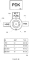
- FIGS. 2A-2D depict an example interface 200.
- the interface 200 can include a first input device 202.
- the first input device can be used for selecting a mode.
- the first input device 202 can be an outer knob, dial, etc. Selection of the mode can include turning the first input device 202 to a corresponding mode label 204a-c.
- a mode output device can display a mode.
- the mode output device can display a different mode in response to engagement of the first input device 202.
- the flight director can operate in a mode associated with the mode selected by the first input device 202.
- Example modes include automatic modes (such as the "autonomous" and "shared” modes previously discussed) and manual modes as previously discussed.
- Example automatic modes include Flight Plan Mode 204b, which causes a top entry in a flight plan of the flight management system to be sent to the flight director, Capture Mode, or any other automatic mode.
- Example manual modes include Heading Mode 204a, which can enter a top entry in the flight plan that specifies a heading of the aerial vehicle and can allow a pilot to steer the nose of the aerial vehicle, Track Mode 204c, which can allow a pilot to control the ground path of the aerial vehicle, Intercept Mode, or any other manual mode.
- the interface 200 can include and/or be in communication with an output device 206 for displaying a parameter associated with the selected mode.
- the interface can include a second input device 208.
- the second input device 208 can be used to cycle through parameters associated with the selected mode.
- the second input device 208 can be an inner knob, dial, etc. Cycling through the parameters associated with the selected mode can include turning the second input device 208.
- the output device 206 can be updated with a current parameter as the second input device 208 is engaged.
- the interface 200 can include a third input device 210.
- the third input device 210 can be used to select a parameter associated with the mode shown on the output device 206.
- the third input device 210 can be a button.
- Engaging the third input device 210 can cause the parameter associated with the selected mode on the third input device 210 and an indication of the selected mode to be transmitted to the flight director.
- the indication of the selected mode can be transmitted to the flight director in response to engagement of the first input device 202.
- a flight plan output device 220 can display entries in a flight plan. The entries in a flight plan can include airport codes, waypoint identifiers, etc.
- FIG. 2A depicts a first example state of the interface 200.
- the first input device 202 can indicate that the flight director is in Flight Plan Mode 204b.
- the output device 206 can indicate that ATL is the next node (e.g., airport, location, landmark, etc.) in the flight plan.
- the flight plan output device 220 can display ATL at the top when the third input device 210 is engaged while the output device 206 displays ATL.
- FIG. 2B depicts a second example state of the interface 200. In the second example state of the interface 200, the second input device 208 is engaged to change the parameter shown in output device 206. The parameter is changed from ATL to PDK.
- the entries shown in the flight plan output device 220 can be shown in the output device 206 in order when the second input device 208 is engaged. For example, when the second input device 208 is turned to the right, the output device 206 can go from displaying ATL to KLOWD and then from KLOWD to PDK. The flight plan output device 220 can display PDK at the top when the third input device 210 is engaged while the output device 206 displays PDK.
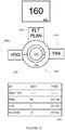
- FIG. 2C depicts a third example state of the interface 200. In the third example state of the interface 200, the first input device 202 can be engaged to select Heading Mode 204a. The output device 206 is updated to show a parameter, 160, associated with the Heading Mode 204a.
- the flight plan output device 220 can display HDG 160 at the top when the third input device 210 is engaged while the output device 206 displays 160.
- FIG. 2D depicts a fourth example state of the interface 200. In the fourth example state of the interface 200, the second input device 208 is engaged to change the parameter shown in output device 206. The parameter is changed from 160 to 180. The flight plan output device 220 can display HDG 180 at the top when the third input device 210 is engaged while the output device 206 displays 180.
- FIG. 3 depicts a flow diagram of an example method (300) for controlling an aerial vehicle according to example embodiments of the present disclosure.
- the method 300 can be performed by a flight management system.
- a first signal can be received from a first input device.
- the first signal can be related to a mode of a flight director.
- the mode can be an automatic mode, such as an autonomous mode and/or a shared mode. Examples of an automatic mode can be the Flight Plan Mode 204b and/or Capture Mode.
- the mode can be a manual mode. Examples of a manual mode can be the Heading Mode 204a the Tracking Mode 204c, and/or Intercept Mode.
- the first input device can be an outer knob, dial, etc. The first signal can be received in response to a turn of the outer knob.
- a parameter related to the mode can be outputted on an output device.
- the parameter can be a numeric parameter when the selected mode uses numerical parameters.
- the parameter can be a numeric parameter representing a degree when the selected mode uses the numeric parameter to determine at what degree heading the nose of the aerial vehicle should be pointed.
- the parameter can be an alphabetic parameter when the selected mode uses alphabetic parameters.
- the parameter can be an alphabetic parameter representing an airport code when the selected mode uses the airport code to determine a route.
- the parameter can be an alphabetic parameter representing waypoint identifier when the selected mode uses the waypoint identifier to determine a route.
- the parameter can include a combination of numerical and alphabetic parameters, or any other symbols.
- a second signal can be received from a second input device.
- the second signal can cause the parameter to change to a new parameter.
- the second input device can be mechanically coupled to the first input device.
- the second input device can be an inner knob, dial, etc.
- the second signal can be received in response to a turn of the inner knob.
- the first input device can surround the second input device.
- An outer circumference of the second input device can be in communication with an inner circumference of the first input device.
- the second input device can be on top of the first input device.
- the new parameter can be outputted on the output device.
- a third signal can be received from a third input device.
- the aerial vehicle can be controlled by the flight director based on the third signal.
- the second input device can be mechanically coupled to the third input device.
- the third input device can be a button.
- the third signal is received in response to a press of the button.
- the second input device can surround the third input device.
- An outer circumference of the third input device can be in communication with an inner circumference of the second input device.
- the third input device can be on top of the second input device.
- Output of the flight management system can be input to the flight director. Input to the flight director can be output from the flight management system.
- the methods and systems described herein can eliminate direct user interaction with the flight director.
- the new parameter can be entered as a top entry in a flight plan in response to the third signal. For example, if the new parameter is an entry in the flight plan, then the new parameter can be moved to the top of the flight plan. As another example, if the new parameter is a heading setting, then the heading of the aerial vehicle as specified by the new parameter can be entered as a top entry in the flight plan in response to the third signal. In an embodiment, input into the flight director can be the top entry in the flight plan.
- FIG. 4 depicts a block diagram of an example computing system that can be used to implement a control system 400 or other systems of the aerial vehicle according to example embodiments of the present disclosure.
- the control system 400 can be in communication with the flight management system 114 and/or the flight director 116.
- the control system 400 can be integrated with the flight management system 114 and/or the flight director 116.
- the control system 400 can include one or more computing device(s) 402.
- the one or more computing device(s) 402 can include one or more processor(s) 404 and one or more memory device(s) 406.
- the one or more processor(s) 404 can include any suitable processing device, such as a microprocessor, microcontroller, integrated circuit, logic device, or other suitable processing device.
- the one or more memory device(s) 406 can include one or more computer-readable media, including, but not limited to, non-transitory computer-readable media, RAM, ROM, hard drives, flash drives, or other memory devices.
- the one or more memory device(s) 406 can store information accessible by the one or more processor(s) 404, including computer-readable instructions 408 that can be executed by the one or more processor(s) 404.
- the instructions 408 can be any set of instructions that when executed by the one or more processor(s) 404, cause the one or more processor(s) 404 to perform operations.
- the instructions 408 can be software written in any suitable programming language or can be implemented in hardware.
- the instructions 408 can be executed by the one or more processor(s) 404 to cause the one or more processor(s) 404 to perform operations, such as the operations for integrating the flight management system with the flight director, as described with reference to FIG. 3 , and/or any other operations or functions of the one or more computing device(s) 402.
- the memory device(s) 406 can further store data 410 that can be accessed by the processors 404.
- the data 410 can include a navigational database, data associated with the navigation system(s), data associated with the control mechanisms, data indicative of a flight plan associated with the vehicle 100, data associated with flight director mode selection, data associated with a flight management system, and/or any other data associated with vehicle 100, as described herein.
- the data 410 can include one or more table(s), function(s), algorithm(s), model(s), equation(s), etc. for navigating the vehicle 100 according to example embodiments of the present disclosure.
- the one or more computing device(s) 402 can also include a communication interface 412 used to communicate, for example, with the other components of system.
- the communication interface 412 can include any suitable components for interfacing with one or more network(s), including for example, transmitters, receivers, ports, controllers, antennas, or other suitable components.
- the one or more computing device(s) 402 can include input and/or output devices 414.
- the input and/or output device(s) 414 can include a keyboard, joystick, multi-way rocker switches, mouse, trackball, touch screen, touch pad, data entry keys, a microphone suitable for voice recognition, a display device and/or any other suitable device.
- the input and/or output device(s) 414 can include the interface 200 of FIGS. 2A-2D .
Landscapes
- Engineering & Computer Science (AREA)
- Aviation & Aerospace Engineering (AREA)
- Physics & Mathematics (AREA)
- General Physics & Mathematics (AREA)
- Automation & Control Theory (AREA)
- Remote Sensing (AREA)
- Radar, Positioning & Navigation (AREA)
- Traffic Control Systems (AREA)
- Business, Economics & Management (AREA)
- Health & Medical Sciences (AREA)
- Artificial Intelligence (AREA)
- Evolutionary Computation (AREA)
- Game Theory and Decision Science (AREA)
- Medical Informatics (AREA)
Description
- The present subject matter relates generally to aerial vehicles.
- One of the largest challenges to safety of flight is pilot automation and flight mode confusion. This is apparent in the systems used to automatically maneuver the aerial vehicle. In current aerial vehicles, the flight management system and the flight director are loosely coupled. Interactions with the flight management system are usually accomplished through a keyboard or cursor interface. Interactions with the flight director are controlled by the mode control panel. The mode control panel also has mechanisms to select which system, the flight management or the flight director, is in charge. The complexity of the current systems provides many opportunities for pilots to misinterpret data presented to them or understanding what the aerial vehicle is about to do. Further, pilots can enter incorrect input into various systems.
- Aspects and advantages of the present disclosure will be set forth in part in the following description, or may be learned from the description, or may be learned through practice of the examples enclosed herein.
- One example aspect of the present disclosure is directed to a method for controlling an aerial vehicle. The method includes receiving a first signal from a first input device, wherein the first signal is related to a mode of a flight director. The method includes outputting a parameter on an output device, wherein the parameter is related to the mode. The method includes receiving a second signal from a second input device, wherein the second signal causes the parameter to change to a new parameter, and wherein the second input device is mechanically coupled to the first input device. The method includes outputting, by the one or more processors, the new parameter on the output device. The method includes receiving, by the one or more processors, a third signal from a third input device, wherein the aerial vehicle is controlled by the flight director based on the third signal, and wherein the second input device is mechanically coupled to the third input device.
- Another example aspect of the present disclosure is directed to a system for controlling an aerial vehicle. The system includes a flight director that controls the aerial vehicle. The system includes a first input device that specifies one or more modes of the flight director. The system includes a second input device that specifies one or more parameters related to the one or more modes, wherein the second input device is mechanically coupled to the first input device. The system includes a third input device that confirms the one or more parameters, wherein the second input device is mechanically coupled to the third input device. The system includes an output device that displays the one or more parameters. The system includes one or more processors. The one or more processor are configured to transmit a signal to the flight director based on an engagement of the third input device, wherein the signal comprises the one or more parameters based on the second input device, and wherein the signal updates the flight director.
- Other example aspects of the present disclosure are directed to systems, methods, aerial vehicles, avionics systems, devices, non-transitory computer-readable media for integrating a flight management system and a flight director of an aerial vehicle. Variations and modifications can be made to these example aspects of the present disclosure.
- These and other features, aspects and advantages of various examples will become better understood with reference to the following description and appended claims. The accompanying drawings, which are incorporated in and constitute a part of this specification, illustrate aspects of the present disclosure and, together with the description, serve to explain the related principles.
- Detailed discussion of embodiments directed to one of ordinary skill in the art are set forth in the specification, which makes reference to the appended figures, in which:
-
FIG. 1 depicts a perspective view of an example portion of an aerial vehicle according to example embodiments of the present disclosure; -
FIGS. 2A-2D depict an example interface; -
FIG. 3 depicts a flow diagram of an example method according to example embodiments of the present disclosure; and -
FIG. 4 depicts a computing system for implementing one or more aspects according to example embodiments of the present disclosure. - Reference now will be made in detail to embodiments, one or more examples of which are illustrated in the drawings. Each example is provided by way of explanation of the embodiments, not limitation of the embodiments. In fact, it will be apparent to those skilled in the art that various modifications and variations can be made in the present disclosure without departing from the scope or spirit of the invention. For instance, features illustrated or described as part of one embodiment can be used with another embodiment to yield a still further embodiment. Thus, it is intended that the present disclosure covers such modifications and variations as come within the scope of the appended claims and their equivalents.
- As used in the specification and the appended claims, the singular forms "a," "an," and "the" include plural referents unless the context clearly dictates otherwise. The use of the term "about" in conjunction with a numerical value refers to within 25% of the stated amount.
- Example aspects of the present disclosure are directed to methods and systems that can allow integration of a flight management system of an aerial vehicle with a flight director of the aerial vehicle. The flight management system of the aerial vehicle can be similar to a global positioning system in a vehicle. The flight director can control the flight of the aerial vehicle. The flight director can operate in automatic modes. The flight director can operate in manual modes.
- The aerial vehicle can utilize a single interface to control both the flight management system and the flight director. In a traditional system, a pilot can intend to make adjustments to an aerial vehicle which may not take effect if the aerial vehicle is in an automatic mode. The single interface can eliminate confusion regarding whether an aerial vehicle is in an automatic mode or a manual mode by using the single interface to make adjustments during all modes.
- Methods and systems according to example embodiments of the present disclosure can integrate the single interface with the flight management system. The integrated single interface and flight management system can provide the input for the flight director. For instance, if the single interface indicates a manual mode, then the flight director can receive the manual instructions from the integrated single interface and flight management system. If the single interface indicates an automatic mode, then the flight director can receive a route (e.g., flight plan, flight path, etc.) from the flight management system.
- In particular implementations, the single interface can include a first input device for selecting a mode. For instance, the first input device can be an outer knob used to select a mode. The single interface can communicate with an output device to display parameters related to the mode selected. The parameter can be a parameter indicative of a flight plan. The parameter can be a numeric parameter when the selected mode uses numerical parameters. For example, the parameter can be a numeric parameter representing a degree when the selected mode uses the numeric parameter to determine at what degree the head of the aerial vehicle should be pointed. The parameter can be an alphabetic parameter when the selected mode uses alphabetic parameters. For example, the parameter can be an alphabetic parameter representing an airport code when the selected mode uses the airport code to determine a route. For example, the parameter can be an alphabetic parameter representing waypoint identifier when the selected mode uses the waypoint identifier to determine a route. The parameter can include a combination of numerical and alphabetic parameters, or any other symbols. The output device can display a numerical parameter when a manual mode is selected by the first input device and an airport code and/or waypoint identifier when an automatic mode is selected by the first input device. The single interface can include a second input device for changing a parameter associated with the mode. For instance, the second input device can be an inner knob used to change the parameter. As the parameter is changed, the output device can be updated to include the changed parameter. The single interface can include a third input device for selecting the parameter. For instance, the third input device can be a button for selecting the parameter. The parameter displayed on the output device can be sent to the flight director for controlling the aerial vehicle when the third input device is engaged. In this way, the systems and methods according to example aspects of the present disclosure have a technical effect of integrating a flight management system of an aerial vehicle with a flight director of the aerial vehicle.
-
FIG. 1 depicts a perspective view of an example portion of anaerial vehicle 100 according to example embodiments of the present disclosure. Theaerial vehicle 100 can include, for instance, acockpit 102, one or more engine(s) 104, and afuselage 106. Theaerial vehicle 100 can include aflight deck 108, which can include one or more display device(s) 110A-B (e.g., multifunctional flight display devices) including one or more display screens. For example, theaerial vehicle 100 can afirst display device 110A and asecond display device 110B. A user (e.g., a flight crew member, a pilot) can be present in the cockpit (e.g., in a seat facing the display device(s) 110A-B). - The
aerial vehicle 100 can include one or more input device(s) 112 (e.g., in the cockpit 102) that can be configured to provide input to one or more system(s) of theaerial vehicle 100. The input device(s) 112 can include any device suitable to accept input from a user for interaction with the systems of theaerial vehicle 100. For example, the input device(s) 112 can include a keyboard, joystick, multi-way rocker switches, mouse, trackball, touch screen, touch pad, data entry keys, a microphone suitable for voice recognition, and/or any other suitable device. The input device(s) 112 can include an outer knob, an inner knob, and a button. In some implementations, the outer knob can be used to select a mode, such as a flight mode, inner knob can be used to cycle through parameters associated with the selected mode, and the button can be used to select a parameter associated with the mode. In some implementations, the input device(s) 112 can be configured to allow the user to interact with a graphic and/or textual data element provided for display on the display device(s) 110A-B. For example, a display device (e.g., thefirst display device 110A) can be used to display parameters associated with the selected mode. - The aerial vehicle can include a
flight management system 114. Theflight management system 114 can include one or more of the input device(s) 112. Theflight management system 114 can be configured to manage the flight control of theaerial vehicle 100. For instance, theflight management system 114 can be configured to implement, manage, and/or control a flight mode, flight path, flight plan, flight trajectory, etc. for theaerial vehicle 100. For example, theflight management system 114 can include and/or determine a route associated with an airport code and/or a waypoint identifier. Theflight management system 114 can be configured to receive input from a user. In some implementations, theflight management system 114 can receive user input via the one or more input device(s) 112. Additionally, and/or alternatively, theflight management system 114 can be associated with a display device (e.g., thefirst display device 110A) that the user can interact with and/or that can be configured to display information associated to theflight management system 114. For example, thefirst display device 110A can include one or more user interfaces. Thefirst display device 110A can be operably coupled with theinput devices 112 such that a user can interact with the user interface (e.g., cursor interaction via trackball, mouse, etc.) and the textual and/or graphical elements included in the user interface. Additionally, and/or alternatively, thefirst display device 110A can include a touch display screen that can allow a user to visualize the user interface on the touch display screen and interact with the user interface (and the flight management system 114) through the touch display screen. Theflight management system 114 can be configured to implement one or more flight mode(s), flight plans, etc. of theaerial vehicle 100 selected by user input and display information associated with the one or more flight mode(s) on a display device (e.g.,first display device 110A). - The
aerial vehicle 100 can include aflight director 116. Theflight director 116 can include one or more of the input device(s) 112. Theflight director 116 can control an autopilot system. Theflight director 116 can be configured to assist in the control of the trajectory of theaerial vehicle 100 with and/or without user (e.g., pilot) interaction. For instance, theflight director 116 can be configured to assist theaerial vehicle 100 to operate in various control modes. For example, theflight director 116 can be configured to assist theaerial vehicle 100 to operate in an "autonomous" control mode (e.g., no user control) and/or a "shared" control mode (e.g., some user control, some autopilot system automated control). In some implementations, theaerial vehicle 100 can operate in a "manual" control mode by which, for example, there is limited-to-no autopilot system automated control of theaerial vehicle 100. Theflight director 116 can include apanel 118 that can be configured to, for example, display information related to the flight director116 (e.g., flight paths, flight plans, routes, selected flight modes, control modes, parameters associated with selected flight modes, etc.). - In some implementations, the
flight director 116 can be associated with a display device (e.g., thefirst display device 110A), such that the display device can display information associated with the flight director 116 (e.g., flight paths, flight plans, routes, selected flight modes, control modes, parameters associated with selected flight modes, etc.). In some implementations, the associated display device (e.g.,first display device 110A) can include one or more user interface(s). For example, thefirst display device 110A can be operably coupled with theinput devices 112 such that a user can interact with the user interface (e.g., cursor interaction via trackball, mouse, etc.) and the textual and/or graphical elements included in the user interface. Additionally, and/or alternatively, thefirst display device 110A can include a touch display screen that can allow a user to visualize the user interface on the touch display screen and interact with the user interface (and the autopilot system 116) through the touch display screen. In some implementations, thepanel 118 can include thefirst display device 110A and/or a display device that can perform similar operations and/or functions, as described herein. - The
aerial vehicle 100 can include aflight mode annunciator 120 that can be configured to inform the flight crew of a past, current, and/or future status of theaerial vehicle 100. For instance, thesecond display device 110B can be associated with theflight mode annunciator 120. Theflight mode annunciator 120 can be configured to display (e.g., via thesecond display device 110B) one or more past, current, and/or future flight mode(s) associated with theaerial vehicle 100, as well as other information associated with the status of theaerial vehicle 100. - The
input devices 112 in accordance with one or more embodiments of the present disclosure will be described in more detail in reference toFIGS. 2A-2D . Theflight management system 114 and/or theflight director 116 can be stored in memory and executed by one or more computing device(s), as shown inFIG. 4 . - The numbers, locations, and/or orientations of the components of example
aerial vehicle 100 are for purposes of illustration and discussion and are not intended to be limiting. Those of ordinary skill in the art, using the disclosures provided herein, shall understand that the numbers, locations, and/or orientations of the components of theaerial vehicle 100 can be adjusted without deviating from the scope of the present disclosure. -
FIGS. 2A-2D depict anexample interface 200. Theinterface 200 can include afirst input device 202. The first input device can be used for selecting a mode. Thefirst input device 202 can be an outer knob, dial, etc. Selection of the mode can include turning thefirst input device 202 to acorresponding mode label 204a-c. In another embodiment, a mode output device can display a mode. The mode output device can display a different mode in response to engagement of thefirst input device 202. The flight director can operate in a mode associated with the mode selected by thefirst input device 202. Example modes include automatic modes (such as the "autonomous" and "shared" modes previously discussed) and manual modes as previously discussed. Example automatic modes includeFlight Plan Mode 204b, which causes a top entry in a flight plan of the flight management system to be sent to the flight director, Capture Mode, or any other automatic mode. Example manual modes includeHeading Mode 204a, which can enter a top entry in the flight plan that specifies a heading of the aerial vehicle and can allow a pilot to steer the nose of the aerial vehicle,Track Mode 204c, which can allow a pilot to control the ground path of the aerial vehicle, Intercept Mode, or any other manual mode. - The
interface 200 can include and/or be in communication with anoutput device 206 for displaying a parameter associated with the selected mode. The interface can include asecond input device 208. Thesecond input device 208 can be used to cycle through parameters associated with the selected mode. Thesecond input device 208 can be an inner knob, dial, etc. Cycling through the parameters associated with the selected mode can include turning thesecond input device 208. Theoutput device 206 can be updated with a current parameter as thesecond input device 208 is engaged. Theinterface 200 can include athird input device 210. Thethird input device 210 can be used to select a parameter associated with the mode shown on theoutput device 206. Thethird input device 210 can be a button. Engaging thethird input device 210 can cause the parameter associated with the selected mode on thethird input device 210 and an indication of the selected mode to be transmitted to the flight director. In another embodiment, the indication of the selected mode can be transmitted to the flight director in response to engagement of thefirst input device 202. A flightplan output device 220 can display entries in a flight plan. The entries in a flight plan can include airport codes, waypoint identifiers, etc. -
FIG. 2A depicts a first example state of theinterface 200. For example, thefirst input device 202 can indicate that the flight director is inFlight Plan Mode 204b. Theoutput device 206 can indicate that ATL is the next node (e.g., airport, location, landmark, etc.) in the flight plan. The flightplan output device 220 can display ATL at the top when thethird input device 210 is engaged while theoutput device 206 displays ATL.FIG. 2B depicts a second example state of theinterface 200. In the second example state of theinterface 200, thesecond input device 208 is engaged to change the parameter shown inoutput device 206. The parameter is changed from ATL to PDK. In an aspect, the entries shown in the flightplan output device 220 can be shown in theoutput device 206 in order when thesecond input device 208 is engaged. For example, when thesecond input device 208 is turned to the right, theoutput device 206 can go from displaying ATL to KLOWD and then from KLOWD to PDK. The flightplan output device 220 can display PDK at the top when thethird input device 210 is engaged while theoutput device 206 displays PDK.FIG. 2C depicts a third example state of theinterface 200. In the third example state of theinterface 200, thefirst input device 202 can be engaged to selectHeading Mode 204a. Theoutput device 206 is updated to show a parameter, 160, associated with theHeading Mode 204a. The flightplan output device 220 can displayHDG 160 at the top when thethird input device 210 is engaged while theoutput device 206 displays 160.FIG. 2D depicts a fourth example state of theinterface 200. In the fourth example state of theinterface 200, thesecond input device 208 is engaged to change the parameter shown inoutput device 206. The parameter is changed from 160 to 180. The flightplan output device 220 can displayHDG 180 at the top when thethird input device 210 is engaged while theoutput device 206 displays 180. -
FIG. 3 depicts a flow diagram of an example method (300) for controlling an aerial vehicle according to example embodiments of the present disclosure. Themethod 300 can be performed by a flight management system. At (302), a first signal can be received from a first input device. The first signal can be related to a mode of a flight director. The mode can be an automatic mode, such as an autonomous mode and/or a shared mode. Examples of an automatic mode can be theFlight Plan Mode 204b and/or Capture Mode. The mode can be a manual mode. Examples of a manual mode can be the HeadingMode 204a theTracking Mode 204c, and/or Intercept Mode. The first input device can be an outer knob, dial, etc. The first signal can be received in response to a turn of the outer knob. - At (304), a parameter related to the mode can be outputted on an output device. The parameter can be a numeric parameter when the selected mode uses numerical parameters. For example, the parameter can be a numeric parameter representing a degree when the selected mode uses the numeric parameter to determine at what degree heading the nose of the aerial vehicle should be pointed. The parameter can be an alphabetic parameter when the selected mode uses alphabetic parameters. For example, the parameter can be an alphabetic parameter representing an airport code when the selected mode uses the airport code to determine a route. For example, the parameter can be an alphabetic parameter representing waypoint identifier when the selected mode uses the waypoint identifier to determine a route. The parameter can include a combination of numerical and alphabetic parameters, or any other symbols.
- At (306), a second signal can be received from a second input device. The second signal can cause the parameter to change to a new parameter. The second input device can be mechanically coupled to the first input device. The second input device can be an inner knob, dial, etc. The second signal can be received in response to a turn of the inner knob. The first input device can surround the second input device. An outer circumference of the second input device can be in communication with an inner circumference of the first input device. The second input device can be on top of the first input device. At (308), the new parameter can be outputted on the output device.
- At (310), a third signal can be received from a third input device. The aerial vehicle can be controlled by the flight director based on the third signal. The second input device can be mechanically coupled to the third input device. The third input device can be a button. The third signal is received in response to a press of the button. The second input device can surround the third input device. An outer circumference of the third input device can be in communication with an inner circumference of the second input device. The third input device can be on top of the second input device. Output of the flight management system can be input to the flight director. Input to the flight director can be output from the flight management system. In an aspect, the methods and systems described herein can eliminate direct user interaction with the flight director. In an embodiment, the new parameter can be entered as a top entry in a flight plan in response to the third signal. For example, if the new parameter is an entry in the flight plan, then the new parameter can be moved to the top of the flight plan. As another example, if the new parameter is a heading setting, then the heading of the aerial vehicle as specified by the new parameter can be entered as a top entry in the flight plan in response to the third signal. In an embodiment, input into the flight director can be the top entry in the flight plan.
-
FIG. 4 depicts a block diagram of an example computing system that can be used to implement acontrol system 400 or other systems of the aerial vehicle according to example embodiments of the present disclosure. In an embodiment, thecontrol system 400 can be in communication with theflight management system 114 and/or theflight director 116. In an embodiment, thecontrol system 400 can be integrated with theflight management system 114 and/or theflight director 116. As shown, thecontrol system 400 can include one or more computing device(s) 402. The one or more computing device(s) 402 can include one or more processor(s) 404 and one or more memory device(s) 406. The one or more processor(s) 404 can include any suitable processing device, such as a microprocessor, microcontroller, integrated circuit, logic device, or other suitable processing device. The one or more memory device(s) 406 can include one or more computer-readable media, including, but not limited to, non-transitory computer-readable media, RAM, ROM, hard drives, flash drives, or other memory devices. - The one or more memory device(s) 406 can store information accessible by the one or more processor(s) 404, including computer-
readable instructions 408 that can be executed by the one or more processor(s) 404. Theinstructions 408 can be any set of instructions that when executed by the one or more processor(s) 404, cause the one or more processor(s) 404 to perform operations. Theinstructions 408 can be software written in any suitable programming language or can be implemented in hardware. In some embodiments, theinstructions 408 can be executed by the one or more processor(s) 404 to cause the one or more processor(s) 404 to perform operations, such as the operations for integrating the flight management system with the flight director, as described with reference toFIG. 3 , and/or any other operations or functions of the one or more computing device(s) 402. - The memory device(s) 406 can further store
data 410 that can be accessed by theprocessors 404. For example, thedata 410 can include a navigational database, data associated with the navigation system(s), data associated with the control mechanisms, data indicative of a flight plan associated with thevehicle 100, data associated with flight director mode selection, data associated with a flight management system, and/or any other data associated withvehicle 100, as described herein. Thedata 410 can include one or more table(s), function(s), algorithm(s), model(s), equation(s), etc. for navigating thevehicle 100 according to example embodiments of the present disclosure. - The one or more computing device(s) 402 can also include a
communication interface 412 used to communicate, for example, with the other components of system. Thecommunication interface 412 can include any suitable components for interfacing with one or more network(s), including for example, transmitters, receivers, ports, controllers, antennas, or other suitable components. - The one or more computing device(s) 402 can include input and/or
output devices 414. For example, the input and/or output device(s) 414 can include a keyboard, joystick, multi-way rocker switches, mouse, trackball, touch screen, touch pad, data entry keys, a microphone suitable for voice recognition, a display device and/or any other suitable device. The input and/or output device(s) 414 can include theinterface 200 ofFIGS. 2A-2D . - Although specific features of various embodiments may be shown in some drawings and not in others, this is for convenience only. In accordance with the principles of the present disclosure, any feature of a drawing may be referenced and/or claimed in combination with any feature of any other drawing.
- This written description uses examples to disclose the invention, including the best mode, and also to enable any person skilled in the art to practice the invention, including making and using any devices or systems and performing any incorporated methods. The patentable scope of the invention is defined by the claims, and may include other examples that occur to those skilled in the art. Such other examples are intended to be within the scope of the claims if they include structural elements that do not differ from the literal language of the claims, or if they include equivalent structural elements with insubstantial differences from the literal languages of the claims.
- Various aspects and embodiments of the present invention are defined by the following numbered clauses:
- 1. A method for controlling an aerial vehicle comprising:
- receiving, by one or more processors, a first signal from a first input device, wherein the first signal is related to a mode of a flight director;
- outputting, by the one or more processors, a parameter on an output device, wherein the parameter is related to the mode;
- receiving, by the one or more processors, a second signal from a second input device, wherein the second signal causes the parameter to change to a new parameter, and wherein the second input device is mechanically coupled to the first input device;
- outputting, by the one or more processors, the new parameter on the output device; and
- receiving, by the one or more processors, a third signal from a third input device, wherein the aerial vehicle is controlled by the flight director based on the third signal, and wherein the second input device is mechanically coupled to the third input device.
- 2. The method of clause 1, wherein the first input device is an outer knob.
- 3. The method of any preceding clause, wherein the second input device is an inner knob, and wherein the first input device surrounds the second input device.
- 4. The method of any preceding clause, wherein the third input device is a button, and wherein the second input device surrounds the third input device.
- 5. The method of any preceding clause, wherein the first signal is received in response to a turn of the outer knob.
- 6. The method of any preceding clause, wherein the second signal is received in response to a turn of the inner knob.
- 7. The method of any preceding clause, wherein the third signal is received in response to a press of the button.
- 8. The method of any preceding clause, wherein a top entry in a flight plan is input into the flight director.
- 9. The method of any preceding clause, wherein a heading of the aerial vehicle is entered as a top entry in a flight plan in response to the third signal.
- 10. The method of any preceding clause, wherein the method is performed by a flight management system.
- 11. A system for controlling an aerial vehicle, the system comprising:
- a flight director that controls the aerial vehicle;
- a first input device that specifies one or more modes of the flight director;
- a second input device that specifies one or more parameters related to the one or more modes, wherein the second input device is mechanically coupled to the first input device;
- a third input device that confirms the one or more parameters, wherein the second input device is mechanically coupled to the third input device;
- an output device that displays the one or more parameters;
- one or more processors configured to:
- transmit a signal to the flight director based on an engagement of the third input device, wherein the signal comprises the one or more parameters based on the second input device, and wherein the signal updates the flight director.
- 12. The system of clause 11, wherein the first input device is an outer knob.
- 13. The system of any of clauses 11 to 12, wherein the second input device is an inner knob, and wherein the first input device surrounds the second input device.
- 14. The system of any of clauses 11 to 13, wherein the third input device is a button, and wherein the second input device surrounds the third input device.
- 15. The system of any of clauses 11 to 14, wherein the mode is an automatic mode.
- 16. The system of any of clauses 11 to 15, wherein the mode is a manual mode.
- 17. The system of any of clauses 11 to 16, wherein a flight management system comprises the one or more processors.
- 18. An aerial vehicle comprising:
- a flight director that controls the aerial vehicle;
- a first input device that specifies one or more modes of the flight director;
- a second input device that specifies one or more parameters related to the one or more modes, wherein the second input device is mechanically coupled to the first input device;
- a third input device that confirms the one or more parameters, wherein the second input device is mechanically coupled to the third input device;
- an output device that displays the one or more parameters;
- a flight management system comprising one or more processors configured to:
- transmit a signal to the flight director based on an engagement of the third input device, wherein the signal comprises the one or more parameters based on the second input device, and wherein the signal updates the flight director.
- 19. The aerial vehicle of clause 18, wherein output of the flight management system is input to the flight director.
- 20. The aerial vehicle of any of clauses 18 to 19, wherein input to the flight director is output from the flight management system.
Claims (15)
- A method (300) for controlling an aerial vehicle (100) comprising:receiving, by one or more processors (404), a first signal from a first input device (202), wherein the first signal is related to a mode of a flight director (116);outputting, by the one or more processors (404), a parameter on an output device (206), wherein the parameter is related to the mode;receiving, by the one or more processors (404), a second signal from a second input device (208), wherein the second signal causes the parameter to change to a new parameter, and wherein the second input device (208) is mechanically coupled to the first input device (202);outputting, by the one or more processors (404), the new parameter on the output device (206); andreceiving, by the one or more processors (404), a third signal from a third input device (210), wherein the aerial vehicle (100) is controlled by the flight director (116) based on the third signal, and wherein the second input device (208) is mechanically coupled to the third input device (210).
- The method (300) of claim 1, wherein the first input device (202) is an outer knob.
- The method (300) of claim 2, wherein the second input device (208) is an inner knob, and wherein the first input device (202) surrounds the second input device (208).
- The method (300) of claim 3, wherein the third input device (210) is a button, and wherein the second input device (208) surrounds the third input device (210).
- The method (300) of any of claims 2 to 4, wherein the first signal is received in response to a turn of the outer knob.
- The method (300) of claim 3 or any claim dependent thereon, wherein the second signal is received in response to a turn of the inner knob.
- The method (300) of claim 4 or any claim dependent thereon, wherein the third signal is received in response to a press of the button.
- The method (300) of any preceding claim, wherein a top entry in a flight plan is input into the flight director (116).
- The method (300) of any preceding claim, wherein a heading of the aerial vehicle (100) is entered as a top entry in a flight plan in response to the third signal.
- The method (300) of any preceding claim, wherein the method is performed by a flight management system (114).
- A system for controlling an aerial vehicle (100), the system comprising:a flight director (116) that controls the aerial vehicle (100);a first input device (202) that specifies one or more modes of the flight director (116);a second input device (208) that specifies one or more parameters related to the one or more modes, wherein the second input device (208) is mechanically coupled to the first input device (202);a third input device (210) that confirms the one or more parameters, wherein the second input device (208) is mechanically coupled to the third input device (210);an output device (206) that displays the one or more parameters;one or more processors (404) configured to:transmit a signal to the flight director (116) based on an engagement of the third input device (210), wherein the signal comprises the one or more parameters based on the second input device (208), and wherein the signal updates the flight director (116).
- The system of claim 11, wherein the first input device (202) is an outer knob.
- The system of claim 12, wherein the second input device (208) is an inner knob, and wherein the first input device (202) surrounds the second input device (208).
- The system of claim 13, wherein the third input device (210) is a button, and wherein the second input device (208) surrounds the third input device (210).
- The system of any of claims 11 to 14, wherein the mode is an automatic mode.
Applications Claiming Priority (1)
| Application Number | Priority Date | Filing Date | Title |
|---|---|---|---|
| US15/223,088 US10108189B2 (en) | 2016-07-29 | 2016-07-29 | Integrated flight management system and flight director |
Publications (2)
| Publication Number | Publication Date |
|---|---|
| EP3276441A1 true EP3276441A1 (en) | 2018-01-31 |
| EP3276441B1 EP3276441B1 (en) | 2019-11-06 |
Family
ID=59506061
Family Applications (1)
| Application Number | Title | Priority Date | Filing Date |
|---|---|---|---|
| EP17183139.9A Active EP3276441B1 (en) | 2016-07-29 | 2017-07-25 | Integrated flight management system and flight director |
Country Status (4)
| Country | Link |
|---|---|
| US (1) | US10108189B2 (en) |
| EP (1) | EP3276441B1 (en) |
| BR (1) | BR102017016220A2 (en) |
| CA (1) | CA2973983C (en) |
Cited By (1)
| Publication number | Priority date | Publication date | Assignee | Title |
|---|---|---|---|---|
| EP3905011A1 (en) * | 2020-04-27 | 2021-11-03 | Honeywell International Inc. | Flight guidance controller interface |
Families Citing this family (4)
| Publication number | Priority date | Publication date | Assignee | Title |
|---|---|---|---|---|
| FR3087019B1 (en) * | 2018-10-09 | 2021-06-18 | Thales Sa | CONTROL CONTROL SYSTEM OF A CONTROL SYSTEM VIA A GRAPHIC INTERFACE AND ASSOCIATED CONTROL PROCESS |
| US11762543B2 (en) * | 2018-12-21 | 2023-09-19 | Honeywell International Inc. | Systems and methods for managing graphical user interfaces for vehicle guidance |
| US11971728B1 (en) | 2020-10-23 | 2024-04-30 | Rockwell Collins, Inc. | Platform guidance system incorporating hierarchical modular arbitration architecture |
| CA3185437A1 (en) * | 2022-06-09 | 2023-12-09 | Bombardier Inc. | Aircraft system controller and associated method |
Citations (3)
| Publication number | Priority date | Publication date | Assignee | Title |
|---|---|---|---|---|
| US6128553A (en) * | 1998-07-24 | 2000-10-03 | Rockwell Collins, Inc. | Menu control knob |
| US20120280087A1 (en) * | 2011-05-03 | 2012-11-08 | Raytheon Company | Unmanned Aerial Vehicle Control Using a Gamepad |
| US8310446B1 (en) * | 2006-08-25 | 2012-11-13 | Rockwell Collins, Inc. | System for integrated coarse and fine graphical object positioning |
Family Cites Families (16)
| Publication number | Priority date | Publication date | Assignee | Title |
|---|---|---|---|---|
| US6405124B1 (en) * | 2000-05-31 | 2002-06-11 | Lockheed Martin Corporation | System and method for offset course guidance |
| US20040162648A1 (en) * | 2003-02-18 | 2004-08-19 | Honeywell International, Inc. | Configurable cockpit information presentation device |
| US7321318B2 (en) | 2004-03-31 | 2008-01-22 | The Boeing Company | Methods and systems for controlling the display of information at an aircraft flight deck |
| US8027756B2 (en) | 2006-12-07 | 2011-09-27 | The Boeing Company | Integrated approach navigation system, method, and computer program product |
| US8358279B2 (en) * | 2007-11-29 | 2013-01-22 | Daesung Electric Co., Ltd | Sensation system |
| US8965601B1 (en) | 2008-09-23 | 2015-02-24 | Rockwell Collins, Inc. | System, module, and method for presenting a flight director-dependent hits pathway on an aircraft display unit |
| US8694184B1 (en) | 2010-09-21 | 2014-04-08 | The Boeing Company | Methods, systems, and apparatus for layered and multi-indexed flight management interface |
| US9424753B2 (en) | 2011-07-08 | 2016-08-23 | General Electric Company | Simplified user interface for an aircraft |
| US9132913B1 (en) | 2013-09-26 | 2015-09-15 | Rockwell Collins, Inc. | Simplified auto-flight system coupled with a touchscreen flight control panel |
| FR2983177B1 (en) | 2011-11-29 | 2014-06-06 | Airbus Operations Sas | INTERACTIVE DIALOGUE DEVICE BETWEEN AN OPERATOR OF AN AIRCRAFT AND A GUIDE SYSTEM FOR SAID AIRCRAFT. |
| US20140018980A1 (en) | 2012-07-12 | 2014-01-16 | General Electric Company | Systems and methods for flight management |
| US8886372B2 (en) * | 2012-09-07 | 2014-11-11 | The Boeing Company | Flight deck touch-sensitive hardware controls |
| US9199724B2 (en) | 2013-05-15 | 2015-12-01 | Honeywell International Inc. | System and method for performing an aircraft automatic emergency descent |
| US9126694B2 (en) | 2013-07-15 | 2015-09-08 | Honeywell International Inc. | Display systems and methods for providing displays having an integrated autopilot functionality |
| GB2523901B (en) * | 2013-09-10 | 2016-01-20 | Messier Dowty Ltd | A lock and aircraft landing gear assembly |
| US10266250B2 (en) * | 2015-06-12 | 2019-04-23 | Bell Helicopter Textron Inc. | Control inceptor management system |
-
2016
- 2016-07-29 US US15/223,088 patent/US10108189B2/en active Active
-
2017
- 2017-07-20 CA CA2973983A patent/CA2973983C/en not_active Expired - Fee Related
- 2017-07-25 EP EP17183139.9A patent/EP3276441B1/en active Active
- 2017-07-28 BR BR102017016220-6A patent/BR102017016220A2/en not_active IP Right Cessation
Patent Citations (3)
| Publication number | Priority date | Publication date | Assignee | Title |
|---|---|---|---|---|
| US6128553A (en) * | 1998-07-24 | 2000-10-03 | Rockwell Collins, Inc. | Menu control knob |
| US8310446B1 (en) * | 2006-08-25 | 2012-11-13 | Rockwell Collins, Inc. | System for integrated coarse and fine graphical object positioning |
| US20120280087A1 (en) * | 2011-05-03 | 2012-11-08 | Raytheon Company | Unmanned Aerial Vehicle Control Using a Gamepad |
Cited By (2)
| Publication number | Priority date | Publication date | Assignee | Title |
|---|---|---|---|---|
| EP3905011A1 (en) * | 2020-04-27 | 2021-11-03 | Honeywell International Inc. | Flight guidance controller interface |
| US11442471B2 (en) | 2020-04-27 | 2022-09-13 | Honeywell International Inc. | Flight guidance controller interface |
Also Published As
| Publication number | Publication date |
|---|---|
| US10108189B2 (en) | 2018-10-23 |
| CA2973983A1 (en) | 2018-01-29 |
| US20180032073A1 (en) | 2018-02-01 |
| CA2973983C (en) | 2019-10-29 |
| BR102017016220A2 (en) | 2018-03-06 |
| EP3276441B1 (en) | 2019-11-06 |
Similar Documents
| Publication | Publication Date | Title |
|---|---|---|
| JP6050040B2 (en) | Simplified user interface for aircraft | |
| EP2827104B1 (en) | Display systems and methods for providing displays having an integrated autopilot functionality | |
| CA2973983C (en) | Integrated flight management system and flight director | |
| US9710145B2 (en) | Human machine interface device for aircraft | |
| EP3232162B1 (en) | System and method for providing aircraft autoflight capability feedback to a pilot | |
| US9616993B1 (en) | Simplified auto-flight system coupled with a touchscreen flight control panel | |
| US6832138B1 (en) | Cockpit instrument panel systems and methods with redundant flight data display | |
| US9459120B2 (en) | Methods and systems for displaying flight information | |
| EP2741053B1 (en) | Method for graphically generating an approach course | |
| US20180268721A1 (en) | System and method to revise vertical profile of a flight plan | |
| CN111292575A (en) | Aircraft augmented reality system and method of operation | |
| US20170291691A1 (en) | Assistance method for assisting flying of an aircraft with restriction of possibilities of adjusting the flying parameters depending on the context, and corresponding device | |
| KR20180015190A (en) | Method and system for route guidance panel | |
| EP3578925B1 (en) | Automatic from-waypoint updating system and method | |
| US10825468B2 (en) | Natural travel mode description system | |
| US9534922B1 (en) | Aircraft recording system, device, and method responsive to a new command not stated in a flight plan | |
| US12197715B2 (en) | Methods and systems for automated contextual navigation of GUI displays | |
| EP4455854B1 (en) | Methods and systems for automated contextual navigation of gui displays | |
| KR20140090477A (en) | Lateral navigation operating apparatus of utility helicopter and method thereof |
Legal Events
| Date | Code | Title | Description |
|---|---|---|---|
| PUAI | Public reference made under article 153(3) epc to a published international application that has entered the european phase |
Free format text: ORIGINAL CODE: 0009012 |
|
| STAA | Information on the status of an ep patent application or granted ep patent |
Free format text: STATUS: THE APPLICATION HAS BEEN PUBLISHED |
|
| AK | Designated contracting states |
Kind code of ref document: A1 Designated state(s): AL AT BE BG CH CY CZ DE DK EE ES FI FR GB GR HR HU IE IS IT LI LT LU LV MC MK MT NL NO PL PT RO RS SE SI SK SM TR |
|
| AX | Request for extension of the european patent |
Extension state: BA ME |
|
| STAA | Information on the status of an ep patent application or granted ep patent |
Free format text: STATUS: REQUEST FOR EXAMINATION WAS MADE |
|
| 17P | Request for examination filed |
Effective date: 20180803 |
|
| RBV | Designated contracting states (corrected) |
Designated state(s): AL AT BE BG CH CY CZ DE DK EE ES FI FR GB GR HR HU IE IS IT LI LT LU LV MC MK MT NL NO PL PT RO RS SE SI SK SM TR |
|
| REG | Reference to a national code |
Ref country code: DE Ref legal event code: R079 Ref document number: 602017008373 Country of ref document: DE Free format text: PREVIOUS MAIN CLASS: G05D0001000000 Ipc: G05D0001100000 |
|
| GRAP | Despatch of communication of intention to grant a patent |
Free format text: ORIGINAL CODE: EPIDOSNIGR1 |
|
| STAA | Information on the status of an ep patent application or granted ep patent |
Free format text: STATUS: GRANT OF PATENT IS INTENDED |
|
| RIC1 | Information provided on ipc code assigned before grant |
Ipc: G08G 5/00 20060101ALI20190410BHEP Ipc: B64D 43/00 20060101ALI20190410BHEP Ipc: G05D 1/10 20060101AFI20190410BHEP Ipc: G05D 1/00 20060101ALI20190410BHEP |
|
| INTG | Intention to grant announced |
Effective date: 20190514 |
|
| GRAS | Grant fee paid |
Free format text: ORIGINAL CODE: EPIDOSNIGR3 |
|
| GRAA | (expected) grant |
Free format text: ORIGINAL CODE: 0009210 |
|
| STAA | Information on the status of an ep patent application or granted ep patent |
Free format text: STATUS: THE PATENT HAS BEEN GRANTED |
|
| AK | Designated contracting states |
Kind code of ref document: B1 Designated state(s): AL AT BE BG CH CY CZ DE DK EE ES FI FR GB GR HR HU IE IS IT LI LT LU LV MC MK MT NL NO PL PT RO RS SE SI SK SM TR |
|
| REG | Reference to a national code |
Ref country code: GB Ref legal event code: FG4D |
|
| REG | Reference to a national code |
Ref country code: CH Ref legal event code: EP Ref country code: AT Ref legal event code: REF Ref document number: 1199627 Country of ref document: AT Kind code of ref document: T Effective date: 20191115 |
|
| REG | Reference to a national code |
Ref country code: DE Ref legal event code: R096 Ref document number: 602017008373 Country of ref document: DE |
|
| REG | Reference to a national code |
Ref country code: IE Ref legal event code: FG4D |
|
| REG | Reference to a national code |
Ref country code: NL Ref legal event code: MP Effective date: 20191106 |
|
| REG | Reference to a national code |
Ref country code: LT Ref legal event code: MG4D |
|
| PG25 | Lapsed in a contracting state [announced via postgrant information from national office to epo] |
Ref country code: NO Free format text: LAPSE BECAUSE OF FAILURE TO SUBMIT A TRANSLATION OF THE DESCRIPTION OR TO PAY THE FEE WITHIN THE PRESCRIBED TIME-LIMIT Effective date: 20200206 Ref country code: BG Free format text: LAPSE BECAUSE OF FAILURE TO SUBMIT A TRANSLATION OF THE DESCRIPTION OR TO PAY THE FEE WITHIN THE PRESCRIBED TIME-LIMIT Effective date: 20200206 Ref country code: FI Free format text: LAPSE BECAUSE OF FAILURE TO SUBMIT A TRANSLATION OF THE DESCRIPTION OR TO PAY THE FEE WITHIN THE PRESCRIBED TIME-LIMIT Effective date: 20191106 Ref country code: PL Free format text: LAPSE BECAUSE OF FAILURE TO SUBMIT A TRANSLATION OF THE DESCRIPTION OR TO PAY THE FEE WITHIN THE PRESCRIBED TIME-LIMIT Effective date: 20191106 Ref country code: LT Free format text: LAPSE BECAUSE OF FAILURE TO SUBMIT A TRANSLATION OF THE DESCRIPTION OR TO PAY THE FEE WITHIN THE PRESCRIBED TIME-LIMIT Effective date: 20191106 Ref country code: GR Free format text: LAPSE BECAUSE OF FAILURE TO SUBMIT A TRANSLATION OF THE DESCRIPTION OR TO PAY THE FEE WITHIN THE PRESCRIBED TIME-LIMIT Effective date: 20200207 Ref country code: PT Free format text: LAPSE BECAUSE OF FAILURE TO SUBMIT A TRANSLATION OF THE DESCRIPTION OR TO PAY THE FEE WITHIN THE PRESCRIBED TIME-LIMIT Effective date: 20200306 Ref country code: LV Free format text: LAPSE BECAUSE OF FAILURE TO SUBMIT A TRANSLATION OF THE DESCRIPTION OR TO PAY THE FEE WITHIN THE PRESCRIBED TIME-LIMIT Effective date: 20191106 Ref country code: NL Free format text: LAPSE BECAUSE OF FAILURE TO SUBMIT A TRANSLATION OF THE DESCRIPTION OR TO PAY THE FEE WITHIN THE PRESCRIBED TIME-LIMIT Effective date: 20191106 Ref country code: SE Free format text: LAPSE BECAUSE OF FAILURE TO SUBMIT A TRANSLATION OF THE DESCRIPTION OR TO PAY THE FEE WITHIN THE PRESCRIBED TIME-LIMIT Effective date: 20191106 |
|
| PG25 | Lapsed in a contracting state [announced via postgrant information from national office to epo] |
Ref country code: RS Free format text: LAPSE BECAUSE OF FAILURE TO SUBMIT A TRANSLATION OF THE DESCRIPTION OR TO PAY THE FEE WITHIN THE PRESCRIBED TIME-LIMIT Effective date: 20191106 Ref country code: HR Free format text: LAPSE BECAUSE OF FAILURE TO SUBMIT A TRANSLATION OF THE DESCRIPTION OR TO PAY THE FEE WITHIN THE PRESCRIBED TIME-LIMIT Effective date: 20191106 Ref country code: IS Free format text: LAPSE BECAUSE OF FAILURE TO SUBMIT A TRANSLATION OF THE DESCRIPTION OR TO PAY THE FEE WITHIN THE PRESCRIBED TIME-LIMIT Effective date: 20200306 |
|
| PG25 | Lapsed in a contracting state [announced via postgrant information from national office to epo] |
Ref country code: AL Free format text: LAPSE BECAUSE OF FAILURE TO SUBMIT A TRANSLATION OF THE DESCRIPTION OR TO PAY THE FEE WITHIN THE PRESCRIBED TIME-LIMIT Effective date: 20191106 |
|
| PG25 | Lapsed in a contracting state [announced via postgrant information from national office to epo] |
Ref country code: EE Free format text: LAPSE BECAUSE OF FAILURE TO SUBMIT A TRANSLATION OF THE DESCRIPTION OR TO PAY THE FEE WITHIN THE PRESCRIBED TIME-LIMIT Effective date: 20191106 Ref country code: DK Free format text: LAPSE BECAUSE OF FAILURE TO SUBMIT A TRANSLATION OF THE DESCRIPTION OR TO PAY THE FEE WITHIN THE PRESCRIBED TIME-LIMIT Effective date: 20191106 Ref country code: RO Free format text: LAPSE BECAUSE OF FAILURE TO SUBMIT A TRANSLATION OF THE DESCRIPTION OR TO PAY THE FEE WITHIN THE PRESCRIBED TIME-LIMIT Effective date: 20191106 Ref country code: CZ Free format text: LAPSE BECAUSE OF FAILURE TO SUBMIT A TRANSLATION OF THE DESCRIPTION OR TO PAY THE FEE WITHIN THE PRESCRIBED TIME-LIMIT Effective date: 20191106 Ref country code: ES Free format text: LAPSE BECAUSE OF FAILURE TO SUBMIT A TRANSLATION OF THE DESCRIPTION OR TO PAY THE FEE WITHIN THE PRESCRIBED TIME-LIMIT Effective date: 20191106 |
|
| REG | Reference to a national code |
Ref country code: DE Ref legal event code: R097 Ref document number: 602017008373 Country of ref document: DE |
|
| REG | Reference to a national code |
Ref country code: AT Ref legal event code: MK05 Ref document number: 1199627 Country of ref document: AT Kind code of ref document: T Effective date: 20191106 |
|
| PG25 | Lapsed in a contracting state [announced via postgrant information from national office to epo] |
Ref country code: SK Free format text: LAPSE BECAUSE OF FAILURE TO SUBMIT A TRANSLATION OF THE DESCRIPTION OR TO PAY THE FEE WITHIN THE PRESCRIBED TIME-LIMIT Effective date: 20191106 Ref country code: SM Free format text: LAPSE BECAUSE OF FAILURE TO SUBMIT A TRANSLATION OF THE DESCRIPTION OR TO PAY THE FEE WITHIN THE PRESCRIBED TIME-LIMIT Effective date: 20191106 |
|
| PLBE | No opposition filed within time limit |
Free format text: ORIGINAL CODE: 0009261 |
|
| STAA | Information on the status of an ep patent application or granted ep patent |
Free format text: STATUS: NO OPPOSITION FILED WITHIN TIME LIMIT |
|
| 26N | No opposition filed |
Effective date: 20200807 |
|
| PG25 | Lapsed in a contracting state [announced via postgrant information from national office to epo] |
Ref country code: SI Free format text: LAPSE BECAUSE OF FAILURE TO SUBMIT A TRANSLATION OF THE DESCRIPTION OR TO PAY THE FEE WITHIN THE PRESCRIBED TIME-LIMIT Effective date: 20191106 Ref country code: AT Free format text: LAPSE BECAUSE OF FAILURE TO SUBMIT A TRANSLATION OF THE DESCRIPTION OR TO PAY THE FEE WITHIN THE PRESCRIBED TIME-LIMIT Effective date: 20191106 |
|
| PG25 | Lapsed in a contracting state [announced via postgrant information from national office to epo] |
Ref country code: IT Free format text: LAPSE BECAUSE OF FAILURE TO SUBMIT A TRANSLATION OF THE DESCRIPTION OR TO PAY THE FEE WITHIN THE PRESCRIBED TIME-LIMIT Effective date: 20191106 |
|
| PG25 | Lapsed in a contracting state [announced via postgrant information from national office to epo] |
Ref country code: MC Free format text: LAPSE BECAUSE OF FAILURE TO SUBMIT A TRANSLATION OF THE DESCRIPTION OR TO PAY THE FEE WITHIN THE PRESCRIBED TIME-LIMIT Effective date: 20191106 |
|
| REG | Reference to a national code |
Ref country code: CH Ref legal event code: PL |
|
| REG | Reference to a national code |
Ref country code: BE Ref legal event code: MM Effective date: 20200731 |
|
| PG25 | Lapsed in a contracting state [announced via postgrant information from national office to epo] |
Ref country code: LU Free format text: LAPSE BECAUSE OF NON-PAYMENT OF DUE FEES Effective date: 20200725 Ref country code: LI Free format text: LAPSE BECAUSE OF NON-PAYMENT OF DUE FEES Effective date: 20200731 Ref country code: CH Free format text: LAPSE BECAUSE OF NON-PAYMENT OF DUE FEES Effective date: 20200731 |
|
| PG25 | Lapsed in a contracting state [announced via postgrant information from national office to epo] |
Ref country code: BE Free format text: LAPSE BECAUSE OF NON-PAYMENT OF DUE FEES Effective date: 20200731 |
|
| PG25 | Lapsed in a contracting state [announced via postgrant information from national office to epo] |
Ref country code: IE Free format text: LAPSE BECAUSE OF NON-PAYMENT OF DUE FEES Effective date: 20200725 |
|
| PG25 | Lapsed in a contracting state [announced via postgrant information from national office to epo] |
Ref country code: TR Free format text: LAPSE BECAUSE OF FAILURE TO SUBMIT A TRANSLATION OF THE DESCRIPTION OR TO PAY THE FEE WITHIN THE PRESCRIBED TIME-LIMIT Effective date: 20191106 Ref country code: MT Free format text: LAPSE BECAUSE OF FAILURE TO SUBMIT A TRANSLATION OF THE DESCRIPTION OR TO PAY THE FEE WITHIN THE PRESCRIBED TIME-LIMIT Effective date: 20191106 Ref country code: CY Free format text: LAPSE BECAUSE OF FAILURE TO SUBMIT A TRANSLATION OF THE DESCRIPTION OR TO PAY THE FEE WITHIN THE PRESCRIBED TIME-LIMIT Effective date: 20191106 |
|
| PG25 | Lapsed in a contracting state [announced via postgrant information from national office to epo] |
Ref country code: MK Free format text: LAPSE BECAUSE OF FAILURE TO SUBMIT A TRANSLATION OF THE DESCRIPTION OR TO PAY THE FEE WITHIN THE PRESCRIBED TIME-LIMIT Effective date: 20191106 |
|
| P01 | Opt-out of the competence of the unified patent court (upc) registered |
Effective date: 20230414 |
|
| REG | Reference to a national code |
Ref country code: DE Ref legal event code: R079 Ref document number: 602017008373 Country of ref document: DE Free format text: PREVIOUS MAIN CLASS: G05D0001100000 Ipc: G05D0001460000 |
|
| PGFP | Annual fee paid to national office [announced via postgrant information from national office to epo] |
Ref country code: GB Payment date: 20250619 Year of fee payment: 9 |
|
| PGFP | Annual fee paid to national office [announced via postgrant information from national office to epo] |
Ref country code: FR Payment date: 20250620 Year of fee payment: 9 |
|
| PGFP | Annual fee paid to national office [announced via postgrant information from national office to epo] |
Ref country code: DE Payment date: 20250620 Year of fee payment: 9 |