EP3276371A1 - Beam steering device and optical apparatus including the same - Google Patents
Beam steering device and optical apparatus including the same Download PDFInfo
- Publication number
- EP3276371A1 EP3276371A1 EP17165694.5A EP17165694A EP3276371A1 EP 3276371 A1 EP3276371 A1 EP 3276371A1 EP 17165694 A EP17165694 A EP 17165694A EP 3276371 A1 EP3276371 A1 EP 3276371A1
- Authority
- EP
- European Patent Office
- Prior art keywords
- beam steering
- light
- steering device
- optical
- lights
- Prior art date
- Legal status (The legal status is an assumption and is not a legal conclusion. Google has not performed a legal analysis and makes no representation as to the accuracy of the status listed.)
- Granted
Links
Images









Classifications
-
- G—PHYSICS
- G02—OPTICS
- G02B—OPTICAL ELEMENTS, SYSTEMS OR APPARATUS
- G02B17/00—Systems with reflecting surfaces, with or without refracting elements
- G02B17/08—Catadioptric systems
- G02B17/0864—Catadioptric systems having non-imaging properties
- G02B17/0868—Catadioptric systems having non-imaging properties for light condensing, e.g. for use with a light emitter
-
- G—PHYSICS
- G01—MEASURING; TESTING
- G01S—RADIO DIRECTION-FINDING; RADIO NAVIGATION; DETERMINING DISTANCE OR VELOCITY BY USE OF RADIO WAVES; LOCATING OR PRESENCE-DETECTING BY USE OF THE REFLECTION OR RERADIATION OF RADIO WAVES; ANALOGOUS ARRANGEMENTS USING OTHER WAVES
- G01S7/00—Details of systems according to groups G01S13/00, G01S15/00, G01S17/00
- G01S7/48—Details of systems according to groups G01S13/00, G01S15/00, G01S17/00 of systems according to group G01S17/00
- G01S7/481—Constructional features, e.g. arrangements of optical elements
- G01S7/4817—Constructional features, e.g. arrangements of optical elements relating to scanning
-
- G—PHYSICS
- G01—MEASURING; TESTING
- G01S—RADIO DIRECTION-FINDING; RADIO NAVIGATION; DETERMINING DISTANCE OR VELOCITY BY USE OF RADIO WAVES; LOCATING OR PRESENCE-DETECTING BY USE OF THE REFLECTION OR RERADIATION OF RADIO WAVES; ANALOGOUS ARRANGEMENTS USING OTHER WAVES
- G01S17/00—Systems using the reflection or reradiation of electromagnetic waves other than radio waves, e.g. lidar systems
- G01S17/02—Systems using the reflection of electromagnetic waves other than radio waves
- G01S17/06—Systems determining position data of a target
- G01S17/42—Simultaneous measurement of distance and other co-ordinates
-
- G—PHYSICS
- G01—MEASURING; TESTING
- G01S—RADIO DIRECTION-FINDING; RADIO NAVIGATION; DETERMINING DISTANCE OR VELOCITY BY USE OF RADIO WAVES; LOCATING OR PRESENCE-DETECTING BY USE OF THE REFLECTION OR RERADIATION OF RADIO WAVES; ANALOGOUS ARRANGEMENTS USING OTHER WAVES
- G01S7/00—Details of systems according to groups G01S13/00, G01S15/00, G01S17/00
- G01S7/48—Details of systems according to groups G01S13/00, G01S15/00, G01S17/00 of systems according to group G01S17/00
- G01S7/4804—Auxiliary means for detecting or identifying lidar signals or the like, e.g. laser illuminators
-
- G—PHYSICS
- G01—MEASURING; TESTING
- G01S—RADIO DIRECTION-FINDING; RADIO NAVIGATION; DETERMINING DISTANCE OR VELOCITY BY USE OF RADIO WAVES; LOCATING OR PRESENCE-DETECTING BY USE OF THE REFLECTION OR RERADIATION OF RADIO WAVES; ANALOGOUS ARRANGEMENTS USING OTHER WAVES
- G01S7/00—Details of systems according to groups G01S13/00, G01S15/00, G01S17/00
- G01S7/48—Details of systems according to groups G01S13/00, G01S15/00, G01S17/00 of systems according to group G01S17/00
- G01S7/481—Constructional features, e.g. arrangements of optical elements
- G01S7/4814—Constructional features, e.g. arrangements of optical elements of transmitters alone
- G01S7/4815—Constructional features, e.g. arrangements of optical elements of transmitters alone using multiple transmitters
-
- G—PHYSICS
- G01—MEASURING; TESTING
- G01S—RADIO DIRECTION-FINDING; RADIO NAVIGATION; DETERMINING DISTANCE OR VELOCITY BY USE OF RADIO WAVES; LOCATING OR PRESENCE-DETECTING BY USE OF THE REFLECTION OR RERADIATION OF RADIO WAVES; ANALOGOUS ARRANGEMENTS USING OTHER WAVES
- G01S7/00—Details of systems according to groups G01S13/00, G01S15/00, G01S17/00
- G01S7/48—Details of systems according to groups G01S13/00, G01S15/00, G01S17/00 of systems according to group G01S17/00
- G01S7/481—Constructional features, e.g. arrangements of optical elements
- G01S7/4818—Constructional features, e.g. arrangements of optical elements using optical fibres
-
- G—PHYSICS
- G02—OPTICS
- G02B—OPTICAL ELEMENTS, SYSTEMS OR APPARATUS
- G02B26/00—Optical devices or arrangements for the control of light using movable or deformable optical elements
- G02B26/02—Optical devices or arrangements for the control of light using movable or deformable optical elements for controlling the intensity of light
-
- G—PHYSICS
- G02—OPTICS
- G02B—OPTICAL ELEMENTS, SYSTEMS OR APPARATUS
- G02B26/00—Optical devices or arrangements for the control of light using movable or deformable optical elements
- G02B26/08—Optical devices or arrangements for the control of light using movable or deformable optical elements for controlling the direction of light
- G02B26/10—Scanning systems
-
- G—PHYSICS
- G02—OPTICS
- G02B—OPTICAL ELEMENTS, SYSTEMS OR APPARATUS
- G02B26/00—Optical devices or arrangements for the control of light using movable or deformable optical elements
- G02B26/08—Optical devices or arrangements for the control of light using movable or deformable optical elements for controlling the direction of light
- G02B26/10—Scanning systems
- G02B26/101—Scanning systems with both horizontal and vertical deflecting means, e.g. raster or XY scanners
-
- G—PHYSICS
- G02—OPTICS
- G02F—OPTICAL DEVICES OR ARRANGEMENTS FOR THE CONTROL OF LIGHT BY MODIFICATION OF THE OPTICAL PROPERTIES OF THE MEDIA OF THE ELEMENTS INVOLVED THEREIN; NON-LINEAR OPTICS; FREQUENCY-CHANGING OF LIGHT; OPTICAL LOGIC ELEMENTS; OPTICAL ANALOGUE/DIGITAL CONVERTERS
- G02F1/00—Devices or arrangements for the control of the intensity, colour, phase, polarisation or direction of light arriving from an independent light source, e.g. switching, gating or modulating; Non-linear optics
- G02F1/29—Devices or arrangements for the control of the intensity, colour, phase, polarisation or direction of light arriving from an independent light source, e.g. switching, gating or modulating; Non-linear optics for the control of the position or the direction of light beams, i.e. deflection
-
- G—PHYSICS
- G02—OPTICS
- G02F—OPTICAL DEVICES OR ARRANGEMENTS FOR THE CONTROL OF LIGHT BY MODIFICATION OF THE OPTICAL PROPERTIES OF THE MEDIA OF THE ELEMENTS INVOLVED THEREIN; NON-LINEAR OPTICS; FREQUENCY-CHANGING OF LIGHT; OPTICAL LOGIC ELEMENTS; OPTICAL ANALOGUE/DIGITAL CONVERTERS
- G02F1/00—Devices or arrangements for the control of the intensity, colour, phase, polarisation or direction of light arriving from an independent light source, e.g. switching, gating or modulating; Non-linear optics
- G02F1/29—Devices or arrangements for the control of the intensity, colour, phase, polarisation or direction of light arriving from an independent light source, e.g. switching, gating or modulating; Non-linear optics for the control of the position or the direction of light beams, i.e. deflection
- G02F1/291—Two-dimensional analogue deflection
-
- G—PHYSICS
- G02—OPTICS
- G02F—OPTICAL DEVICES OR ARRANGEMENTS FOR THE CONTROL OF LIGHT BY MODIFICATION OF THE OPTICAL PROPERTIES OF THE MEDIA OF THE ELEMENTS INVOLVED THEREIN; NON-LINEAR OPTICS; FREQUENCY-CHANGING OF LIGHT; OPTICAL LOGIC ELEMENTS; OPTICAL ANALOGUE/DIGITAL CONVERTERS
- G02F2203/00—Function characteristic
- G02F2203/70—Semiconductor optical amplifier [SOA] used in a device covered by G02F
Definitions
- Apparatuses consistent with example embodiments relate to optical devices and optical apparatuses, and more particularly, to beam steering devices and optical apparatuses including the beam steering devices.
- a typical non-mechanical beam steering method is a steering method using a micro-electro-mechanical system (MEMS) mirror.
- MEMS micro-electro-mechanical system
- this method also has problems in terms of the field of view (FOV) and light transmitting distance.
- Example embodiments may address at least the above problems and/or disadvantages and other disadvantages not described above. Also, the example embodiments are not required to overcome the disadvantages described above, and may not overcome any of the problems described above.
- Example embodiments provide beam steering devices configured to improve or increase the accuracy, precision, and speed of spatial analysis/measurement processes.
- Example embodiments provide beam steering devices capable of scanning objects (subjects) at high speed.
- Example embodiments provide beam steering devices capable of simultaneously emitting and steering a plurality of beams having multiple wavelengths.
- Example embodiments provide optical apparatuses (for example, LiDAR apparatuses) including the beam steering devices.
- a beam steering device including a light source configured to generate input lights having first different wavelengths, a multiplexer configured to simultaneously receive the generated input lights, and multiplex the received input lights into a multiplexed light, and an optical splitter configured to split the multiplexed light.
- the beam steering device further includes an optical modulator configured to modulate the split light, and an emitter configured to simultaneously emit output lights having second different wavelengths to different points arranged in a first direction, based on the modulated light.
- the emitted output lights may be moved in a second direction different from the first direction.
- the first direction may be perpendicular to the second direction.
- Either one or both of the emitter and the optical modulator may include waveguides, the first direction may be parallel to an extension direction of the waveguides, and the second direction may be perpendicular to the extension direction of the waveguides.
- Either one or both of the emitter and the optical modulator may include waveguides, and the first direction may be parallel to an extension direction of the waveguides.
- the optical modulator may include a phase modulator.
- the light source may include laser sources or a multimode laser source, wherein the laser sources or the multimode laser source may be configured to generate lasers having the first different wavelengths as the generated input lights.
- the light source may include a laser source configured to generate a laser having a wavelength, and a wavelength converter configured to divide the generated laser into lasers having the first different wavelengths as the generated input lights.
- the light source may include a light emitting diode (LED) configured to generate light, and a multi-band pass filter configured to divide the generated light into the generated input lights.
- LED light emitting diode
- Each of the generated input lights may have a pulse waveform.
- any one or any combination of the optical splitter, the optical modulator, and the emitter may include any one or any combination of a group IV element, a compound including a group IV element, a group III-V compound, an oxide, a nitride, and a polymer.
- the beam steering device may further include an amplifier disposed between the multiplexer and the emitter, and having a semiconductor optical amplifier (SOA) structure.
- SOA semiconductor optical amplifier
- An optical apparatus may include the beam steering device, a light receiver configured to receive light that is emitted from the beam steering device and reflected from an object, and a circuit connected to either one or both of the beam steering device and the light receiver.
- the optical apparatus may further include a demultiplexer disposed between the object and the light receiver, and configured to demultiplex the reflected light, and divide the demultiplexed light into reflected lights having third different wavelengths, the light receiver may be further configured to receive the reflected lights.
- a demultiplexer disposed between the object and the light receiver, and configured to demultiplex the reflected light, and divide the demultiplexed light into reflected lights having third different wavelengths
- the light receiver may be further configured to receive the reflected lights.
- the light receiver may include photo detecting elements, and the optical apparatus may be configured to acquire information of the third different wavelengths of the reflected lights, using the photo detecting elements, and analyze information of the object, based on the acquired information.
- the optical apparatus may be a LiDAR apparatus.
- a beam steering device including an input coupler configured to simultaneously receive input lights having first different wavelengths, and an output coupler configured to simultaneously emit output lights having second different wavelengths to different points arranged in a first direction, and move the emitted output lights in a second direction different from the first direction, based on the received input lights.
- the beam steering device may further include waveguides disposed between the input coupler and the output coupler, the first direction may be parallel to an extension direction of the waveguides, and the second direction may be perpendicular to the extension direction of the waveguides.
- the beam steering device may further include an optical modulator disposed between the input coupler and the output coupler, and configured to move the emitted output lights in the second direction, based on the received input lights.
- the received input lights may include lasers having the first different wavelengths.
- the input coupler may include a multiplexer configured to simultaneously receive the input lights, and multiplex the received input lights.
- An optical apparatus may include the beam steering device, a light receiver configured to receive light that is emitted from the beam steering device and reflected from an object; and a circuit connected to either one or both of the beam steering device and the light receiver.
- the optical apparatus may further include a demultiplexer disposed between the object and the light receiver, and configured to demultiplex the reflected light, and divide the demultiplexed light into reflected lights having third different wavelengths, and the light receiver may be further configured to receive the reflected lights.
- a demultiplexer disposed between the object and the light receiver, and configured to demultiplex the reflected light, and divide the demultiplexed light into reflected lights having third different wavelengths
- the light receiver may be further configured to receive the reflected lights.
- the optical apparatus may be a LiDAR apparatus.
- a beam steering device including a multiplexer configured to simultaneously receive input lights having first different wavelengths, and multiplex the received input lights into a multiplexed light, and an optical splitter configured to split the multiplexed light.
- the beam steering apparatus further includes an optical modulator configured to modulate the split light, and an emitter configured to simultaneously emit output lights having second different wavelengths to different points arranged in a first direction and of an object, and move the emitted output lights in a second direction different from the first direction, based on the modulated light.
- the beam steering device may further include laser sources configured to generate lasers having the first different wavelengths, and input couplers configured to simultaneously receive the generated lasers, and transmit the received lasers to the multiplexer as the input lights.
- Either one or both of the emitter and the optical modulator may include a substrate, an insulative layer disposed on the substrate, and waveguides disposed on the insulative layer.
- the first direction may be parallel to an extension direction of the waveguides, and the second direction may be perpendicular to the extension direction of the waveguides.
- the beam steering device may further include a cover layer disposed on the multiplexer, the optical splitter, the optical modulator, and the emitter.
- An optical apparatus may include the beam steering device, and a demultiplexer configured to receive light that is reflected from the object, demultiplex the reflected light, and divide the demultiplexed light into reflected lights having third different wavelengths.
- the optical apparatus may further include a filter configured to filter the reflected lights, and a light receiver configured to receive the filtered reflected lights.
- the term "and/or" includes any and all combinations of one or more of the associated listed items. Expressions such as “at least one of,” when preceding a list of elements, modify the entire list of elements and do not modify the individual elements of the list.
- first the terms “first,” “second,” etc. may be used herein to describe various elements, components, regions, layers and/or sections, these elements, components, regions, layers and/or sections may not be limited by these terms. These terms are only used to distinguish one element, component, region, layer or section from another element, component, region, layer or section. Thus, a first element, component, region, layer or section discussed below could be termed a second element, component, region, layer or section without departing from the teachings of example embodiments.
- spatially relative terms such as “beneath,” “below,” “lower,” “above,” “upper” and the like, may be used herein for ease of description to describe one element or feature's relationship to another element(s) or feature(s) as illustrated in the figures. It will be understood that the spatially relative terms are intended to encompass different orientations of the device in use or operation in addition to the orientation depicted in the figures. For example, if the device in the figures is turned over, elements described as “below” or “beneath” other elements or features would then be oriented “above” the other elements or features. Thus, the term “below” can encompass both an orientation of above and below. The device may be otherwise oriented (rotated 90 degrees or at other orientations) and the spatially relative descriptors used herein interpreted accordingly.
- Example embodiments are described herein with reference to cross-sectional illustrations that are schematic illustrations of idealized embodiments (and intermediate structures) of example embodiments. As such, variations from the shapes of the illustrations as a result, for example, of manufacturing techniques and/or tolerances, are to be expected. Thus, example embodiments may not be construed as limited to the shapes of regions illustrated herein but are to include deviations in shapes that result, for example, from manufacturing. For example, an implanted region illustrated as a rectangle will have rounded or curved features and/or a gradient of implant concentration at its edges rather than a binary change from implanted to non-implanted region.
- a buried region formed by implantation may result in some implantation in the region between the buried region and the surface through which the implantation takes place.
- the regions illustrated in the figures are schematic in nature and their shapes are not intended to illustrate the actual shape of a region of a device and are not intended to limit the scope of example embodiments.
- beam steering devices and optical apparatuses including the beam steering devices will be described according to example embodiments with reference to the accompanying drawings.
- the widths and thicknesses of layers or regions may be exaggerated for clarity or ease of description.
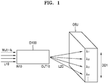
- FIGS. 1 and 2 are schematic views illustrating a beam steering device D100 according to an example embodiment.
- the beam steering device D100 may include an input coupler IN10 and an output coupler OUT10.
- a plurality of lights (beams) L10 having different wavelengths may be simultaneously input through the input coupler IN10.
- multi-wavelength (multi- ⁇ ) light L10 may be input through the input coupler IN10.
- a plurality of output lights (beams) L20 having different wavelengths may be simultaneously emitted toward an object OBJ through the output coupler OUT10.
- the plurality of output lights L20 may be simultaneously emitted to different points arranged in a first direction DD1.
- the points toward which the output lights L20 are emitted may be one-dimensionally arranged.
- the output lights L20 may be simultaneously emitted toward a plurality of points that are one-dimensionally arranged in a line.
- the wavelengths of the output lights L20 may include a first wavelength ⁇ 1 , a second wavelength ⁇ 2 , a third wavelength ⁇ 3 , a fourth wavelength ⁇ 4 , etc.
- the illustrated structure of the object OBJ is an example. That is, the object OBJ may have a different structure, size, etc.
- the object OBJ is not limited to a type.
- the object OBJ may be a space or anything existing in a space.
- the beam steering device D100 may simultaneously emit the plurality of output lights L20 having different wavelengths to detect/search a plurality of points in the first direction DD1.
- the beam steering device D100 may vary (change) the emission directions of the output lights L20 in a direction different from the first direction DD1. This will now be described with reference to FIG. 2 .
- the beam steering device D100 may be configured to change the emission directions of the output lights L20 in a second direction DD2 different from the first direction DD1.
- the second direction DD2 may be perpendicular to the first direction DD1.
- the emission directions of the output lights L20 may be varied in the second direction DD2 by optical modulation performed in the beam steering device D100.
- the emission directions of the output lights L20 having different wavelengths may vary with time in the second direction DD2 as a result of the optical modulation.
- the second direction DD2 may be referred to as a "scanning direction.”
- the beam steering device D100 may perform a scanning operation while changing the emission directions of the output lights L20 in the second direction DD2. Therefore, the beam steering device D100 may perform a two-dimensional scanning operation at a relatively high speed compared to point-by-point beam steering devices.
- FIG. 3 is a schematic view illustrating a beam steering device D10 according to a comparative example.
- the beam steering device D10 of the comparative example may perform a point-by-point scanning operation.
- the beam steering device D10 of the comparative example may scan an object OBJ while moving an output light (beam) having a single wavelength ⁇ 1 in a scanning direction.
- the output light having a single wavelength ⁇ 1 may be emitted to a first point at a first time point T1, a second point at a second time point T2, a third point at a third time point T3, a fourth point at a fourth time point T4, and a fifth point at a fifth time point T5.
- the beam steering device D10 performs a one-dimensional scanning operation.
- Complex and difficult techniques may be used to perform a two-dimensional scanning operation, using the beam steering device D10.
- the speed, accuracy, and precision of the scanning operation may be low.
- the accuracy and precision of detection may be low because of a detection time difference.
- the accuracy and precision of detection/analysis may be decreased as the speed of scanning is decreased.
- a two-dimensional scanning operation may be performed at a high speed by simultaneously emitting the plurality of output lights L20 having different wavelengths.
- the speed of detection/analysis may be increased, and the accuracy and precision of detection/analysis may be markedly improved.
- FIG. 4 is a block diagram illustrating an example configuration of the beam steering device D100 depicted in FIG. 1 .
- the beam steering device D100 is indicated using a reference numeral 1000.
- a light source unit 100 may generate a plurality of lights L11 having different wavelengths.
- the plurality of lights L11 may be referred to as multi-wavelength (multi- ⁇ ) electromagnetic waves.
- the plurality of lights L11 may be a plurality of lasers (laser beams) having different wavelengths.
- the plurality of lights L11 may be another kind of light other than a laser.
- the light source unit 100 may generate the plurality of lights L11 at the same time.
- a multiplexer (MUX) 200 may simultaneously receive and multiplex the plurality of lights L11 generated by the light source unit 100.
- the multiplexer 200 may have a general optical multiplexer structure.
- the multiplexer 200 may also function as an input coupler.
- An optical splitter 300 may split the light multiplexed by the multiplexer 200.
- the optical splitter 300 may be a beam splitter.
- Each of lights (beams) split by the optical splitter 300 may have multiple wavelengths (multi- ⁇ ).
- An optical modulator 400 may modulate the multiplexed light split by the optical splitter 300.
- the optical modulator 400 may modulate light by various methods.
- the optical modulator 400 may modulate the phase of the light split by the optical splitter 300.
- the optical modulator 400 may modulate the amplitude of the light split by the optical splitter 300.
- the optical modulator 400 may modulate both the phase and amplitude of the light split by the optical splitter 300.
- the optical modulator 400 may have other optical modulation functions.
- the optical modulator 400 may perform optical modulation by using a method such as an electric method, a magnetic method, a thermal method, or a mechanical method.
- the optical modulator 400 may include at least one phase shifter (or phase shifting element), and the phase shifter may include at least one selected from the group consisting of a gain element, an all-pass filter, a Bragg grating, a dispersive material element, a wavelength tuning element, and a phase tuning element.
- an actuation mechanism of the optical modulator 400 may include at least one selected from the group consisting of a thermo-optic actuation mechanism, an electro-optic actuation mechanism, an electroabsorption actuation mechanism, a free carrier absorption actuation mechanism, a magneto-optic actuation mechanism, a liquid crystal actuation mechanism, and an all-optical actuation mechanism.
- the actuation mechanism of the optical modulator 400 may be related to the above-described phase tuning.
- the phase shifter and the actuation mechanism of the optical modulator 400 of the example embodiment are not limited to the above examples.
- An emitting portion (emitter) 500 may receive light from the optical modulator 400 and may simultaneously emit a plurality of output lights L22.
- the output lights L22 may have different wavelengths (for example, wavelengths ⁇ 1 , ⁇ 2 , ⁇ 3 , ..., and ⁇ n ).
- the plurality of output lights L22 may be emitted to different points arranged in a first direction DD1.
- the wavelengths of the output lights L22 may correspond to or may be similar to the wavelengths of the lights L11 generated by the light source unit 100.
- the output lights L22 may correspond to the output lights L20 described with reference to FIG. 1 .
- the emission directions of the output lights L22 may be varied in a second direction DD2 different from the first direction DD1.
- the optical modulator 400 performs a modulation operation such as a phase modulation operation on light (split lights)
- the emission directions of the output lights L22 may be varied in the second direction DD2.
- the second direction DD2 may be perpendicular to the first direction DD1.
- the first direction DD1 and the second direction DD2 may correspond to the first direction DD1 and the second direction DD2 described with reference to FIG. 2 .
- the second direction DD2 may be referred to as a scanning direction.
- the emitter 500 may be an output coupler.
- the emitter 500 may include a plurality of waveguides.
- the emitter 500 may further include grating structures formed on the waveguides.
- the grating structures may be designed to direct a beam having a wavelength in a direction.
- the configuration of the emitter 500 is not limited thereto. That is, the configuration of the emitter 500 may be variously modified.
- the beam steering device 1000 may include the multiplexer 200, the optical splitter 300, the optical modulator 400, and the emitter 500.
- the multiplexer 200 may be an input coupler
- the emitter 500 may be an output coupler.
- the multiplexer 200, the optical splitter 300, the optical modulator 400, and the emitter 500 may form a single device (an optical semiconductor device), and the light source unit 100 may be provided separately from the single device and may emit a plurality of lights L11 toward the multiplexer 200. In a broad sense, however, the light source unit 100 may be considered as a part of the beam steering device 1000.
- the beam steering device 1000 includes the light source unit 100, the multiplexer 200, the optical splitter 300, the optical modulator 400, and the emitter 500. That is, the multiplexer 200, the optical splitter 300, the optical modulator 400, and the emitter 500 may be provided on a single chip, or the light source unit 100, the multiplexer 200, the optical splitter 300, the optical modulator 400, and the emitter 500 may be provided on a single chip.
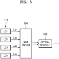
- FIG. 5 is a block diagram illustrating a light source unit and an input unit applicable to a beam steering device according to an example embodiment.
- a light source unit 110 may include a plurality of laser sources LD1 to LD4. Although four laser sources LD1 to LD4 are illustrated, the number of the laser sources may vary.
- the laser sources LD1 to LD4 may be laser diodes.
- the laser sources LD1 to LD4 may generate a plurality of lasers (laser beams) having different wavelengths (for example, wavelengths ⁇ 01 , ⁇ 02 , ⁇ 03 , and ⁇ 04 ).
- the plurality of lasers having different wavelengths ⁇ 01 , ⁇ 02 , ⁇ 03 , and ⁇ 04 that are generated by the laser sources LD1 to LD4 may be input to a multiplexer 200 and may be multiplexed.
- the multiplexer 200 may be considered as an input coupler (input unit).
- the light multiplexed by the multiplexer 200 may be split by an optical splitter 300.
- a configuration after the optical splitter 300 may be substantially the same as or similar to that described with reference to FIG. 4 .
- a multimode laser source may be used instead of the plurality of laser sources LD1 to LD4.
- the multimode laser source may generate a plurality of lasers (laser beams) having different wavelengths.
- FIG. 6 is a block diagram illustrating a light source unit and an input unit applicable to a beam steering device according to another example embodiment.
- lasers having different wavelengths ⁇ 01 , ⁇ 02 , ⁇ 03 , and ⁇ 04 that are generated by laser sources LD1 to LD4 may be input to different input couplers IN1 to IN4, respectively.
- the input couplers IN1 to IN4 may constitute an "input unit 150."
- the input couplers IN1 to IN4 may have an optical fiber structure or another structure.
- the plurality of lights may be multiplexed by a multiplexer 200 and may then be split by an optical splitter 300.
- a configuration after the optical splitter 300 may be substantially the same as or similar to that described with reference to FIG. 4 .
- the input couplers IN1 to IN4 and the multiplexer 200 illustrated in FIG. 6 may be connected to each other by an optical waveguide. In some cases, the combination of the input couplers IN1 to IN4 and the multiplexer 200 may be considered as an "input unit.”
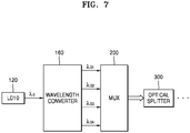
- FIG. 7 is a block diagram illustrating a light source unit and an input unit applicable to a beam steering device according to another example embodiment.
- a light source unit 120 may include a laser source LD10 configured to generate a laser having a single wavelength ⁇ 0 . That is, the light source unit 120 may be constituted by a single laser source LD10.
- a wavelength converter 160 may divide the laser generated by the laser source LD10 into a plurality of lasers having different wavelengths (for example, wavelengths ⁇ 01 , ⁇ 02 , ⁇ 03 , and ⁇ 04 ).
- the wavelength converter 160 may include an input coupler, an optical divider, and a plurality of wavelength converting elements. A laser input to the input coupler may be divided by the optical divider, and the wavelength of the divided laser may be converted by the wavelength converting elements.
- a plurality of lights having different wavelengths may be output from the wavelength converter 160.
- the lights may be multiplexed by a multiplexer 200 and may then be split by an optical splitter 300.
- a configuration after the optical splitter 300 may be equal or similar to that described with reference to FIG. 4 .
- the above-described configuration of the wavelength converter 160 is an example. That is, the configuration of the wavelength converter 160 may be variously modified.
- the combination of the laser source LD10 and the wavelength converter 160 illustrated in FIG. 7 may be considered as a "light source unit.” That is, it may be considered that such a light source unit generates a plurality of lights having different wavelengths (for example, wavelengths ⁇ 01 , ⁇ 02 , ⁇ 03 , and ⁇ 04 ).
- a portion of the wavelength converter 160 or at least a portion of the multiplexer 200 may be considered as an "input coupler.”
- the combination of the wavelength converter 160 and the multiplexer 200 may be considered as an input coupler.
- FIG. 8 is a block diagram illustrating a light source unit and an input unit applicable to a beam steering device according to another example embodiment.
- a light source unit 130 may include a light emitting diode (LED).
- the LED may be a white LED.
- the LED may be a device capable of emitting a wideband light.
- a multi-band pass filter 170 may divide the light generated by the light source unit 130.
- a plurality of lights having a plurality of wavelengths (for example, wavelengths ⁇ 11 , ⁇ 12 , ⁇ 13 , and ⁇ 14 ) may be output through the multi-band pass filter 170. Then, the plurality of lights may be multiplexed by a multiplexer 200 and may then be split by an optical splitter 300.
- a configuration after the optical splitter 300 may be equal or similar to that described with reference to FIG. 4 .
- the combination of the LED (that is, the light source unit 130) and the multi-band pass filter 170 illustrated in FIG. 8 may be considered as a "light source unit.” It may be considered that such a light source unit generates a plurality of lights having different wavelengths.
- the multiplexer 200 may be considered as an "input coupler.”
- FIG. 9 is a plan view illustrating light split by an optical splitter 300A applicable to a beam steering device according to an example embodiment.
- a light multiplexed by a multiplexer may be input to the optical splitter 300A and may be split by the optical splitter 300A.
- the split lights may be output (may propagate) through a plurality of optical path elements W10.
- the optical path elements W10 may be waveguides.
- the optical path elements W10 may include first to eighth optical path elements w11 to w18.
- the first to eighth optical path elements w11 to w18 are examples. That is, the number of the optical path elements W10 may vary.
- Light output (propagating) through each of the first to eighth optical path elements w11 to w18 may have multiple wavelengths.
- the light output (propagating) through each of the first to eighth optical path elements w11 to w18 may include lights having wavelengths ⁇ 01 , ⁇ 02 , ⁇ 03 , and ⁇ 04 illustrated in FIG. 5 , for example.
- the optical splitter 300A may have a multimode interference (MMI) structure or another structure.
- the optical splitter 300A may use a multi-step beam splitting structure to increase the number of split beams.
- the structure of the optical splitter 300A may be variously modified.
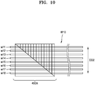
- FIG. 10 is a plan view illustrating light modulation by an optical modulator 400A applicable to a beam steering device according to an example embodiment.
- the optical modulator 400A may be placed on a plurality of optical path elements W10.
- the optical modulator 400A may be placed above or below the optical path elements W10. It may be considered that the optical path elements W10 are included in the optical modulator 400A.
- the optical path elements W10 may be those extending from the optical path elements W10 described with reference to FIG. 9 .
- the optical path elements W10 may include first to eighth optical path elements w11 to w18.
- the number of the optical path elements W10 is not limited thereto.
- the optical modulator 400A may modulate lights propagating through the optical path elements W10.
- the optical modulator 400A may modulate lights propagating through the first to eighth optical path elements w11 to w18.
- a light propagating through the first optical path element w11 may be modulated to a first degree
- a light propagating through the second optical path element w12 may be modulated to a second degree
- a light propagating through the third optical path element w13 may be modulated to a third degree
- a light propagating through the fourth optical path element w14 may be modulated to a fourth degree
- a light propagating through the fifth optical path element w15 may be modulated to a fifth degree
- a light propagating through the sixth optical path element w16 may be modulated to a sixth degree
- a light propagating through the seventh optical path element w17 may be modulated to a seventh degree
- a light propagating through the eighth optical path element w18 may be modulated to an eighth degree.
- lights propagating through the first to eighth optical path elements w11 to w18 may be modulated to different degrees.
- the wavefronts of lights output from the first to eighth optical path elements w11 to w18 may be adjusted to control the directions of the output lights (beams).
- the emission direction of the output light may be varied in a direction such as a second direction DD2 owing to optical modulation performed by the optical modulator 400A.
- the structure and operational mechanism of the optical modulator 400A may be variously modified.
- the optical modulator 400A may be configured to perform phase modulation, amplitude modulation, or phase-amplitude modulation.
- the optical modulator 400A may perform optical modulation by using a method such as an electric method, a magnetic method, a thermal method, or a mechanical method.
- the structure, size, and number of the optical path elements W10 illustrated in FIG. 10 may be variously modified.
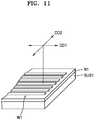
- FIG. 11 is a perspective view illustrating a relationship between a steering direction and waveguides applicable to a beam steering device according to an example embodiment.
- the beam steering device may include a plurality of waveguides W1 formed on a substrate SUB1.
- An insulative layer N1 may be provided on the substrate SUB1, and the waveguides W1 may be arranged on the insulative layer N1.
- the insulative layer N1 is optional. That is, the insulative layer N1 may not be included in example embodiments.
- the waveguides W1 may extend in a direction.
- the waveguides W1 may be arranged in parallel with each other.
- the plurality of waveguides W1 may be included in the output coupler OUT10 or the emitter 500 illustrated with reference to FIG. 1 or 4 .
- the output coupler OUT10 and the emitter 500 may include the plurality of waveguides W1.
- Each of the waveguides W1 may have a grating structure.
- the characteristics or directions of lights (beams) output from the waveguides W1 may vary according to the shapes, sizes, or pattern intervals of the grating structures of the waveguides W1.
- the waveguides W1 may be considered as a grating coupler.
- the optical modulator 400 illustrated in FIG. 4 may include the plurality of waveguides W1. In this case, the optical modulator 400 may modulate lights propagating through the plurality of waveguides W1.
- the first direction DD1 described with reference to FIGS. 1 and 2 may be parallel to an extension direction of the waveguides W1 illustrated in FIG. 11
- the second direction DD2 may be perpendicular to the extension direction of the waveguides W1 illustrated in FIG. 11 .
- a plurality of output lights (refer to the output lights L20 illustrated in FIG. 1 ) may spread in a direction parallel to the extension direction of the waveguides W1, and as a result of the optical modulation, the emission directions of the output lights (refer to the output lights L20 illustrated in FIG. 1 ) may be varied in a direction perpendicular to the extension direction of the waveguides W1.
- the structure and extension direction of the waveguides W1 illustrated in FIG. 11 are examples. That is, the structure and extension direction of the waveguides W1 may be variously modified. In addition, the relationship between the extension direction of the waveguides W1 and a steering direction is not limited to the description presented above.
- FIG. 12 is a cross-sectional view schematically illustrating a beam steering device provided in the form of a single device (semiconductor device), according to an example embodiment.
- the beam steering device may include an input coupler E10 and an output coupler E40 that are arranged on a substrate SUB10.
- the beam steering device may further include an optical splitter E20 and an optical modulator E30 that are arranged between the input coupler E10 and the output coupler E40.
- An insulative layer N10 may be optionally provided on the substrate SUB10, and the input coupler E10, the optical splitter E20, the optical modulator E30, and the output coupler E40 may be arranged on the insulative layer N10.
- Optical waveguide(s) may be provided between two neighboring elements, that is, between the input coupler E10 and the optical splitter E20, between the optical splitter E20 and the optical modulator E30, and between the optical modulator E30 and the output coupler E40.
- the input coupler E10 may be configured to receive a plurality of lights having different wavelengths.
- the input coupler E10 may include a multiplexer.
- the optical splitter E20 may have a multimode interference (MMI) structure or another structure.
- MMI multimode interference
- the optical modulator E30 may perform an optical modulation operation by using an electric method or another method such as a magnetic method, a thermal method, or a mechanical method.
- the optical modulator E30 may use various modulation methods such as a phase modulation method or an amplitude modulation method.
- the optical modulator E30 may include a plurality of waveguides and may modulate beams propagating through the waveguides.
- the output coupler E40 may include a plurality of waveguides and grating structures respectively formed on the waveguides.
- the structures of the input coupler E10, the optical splitter E20, the optical modulator and the output coupler E40 are not limited to those described above and may be variously modified.
- a cover layer C10 may be further provided on the substrate SUB10 to cover the input coupler E10, the optical splitter E20, the optical modulator E30, and the output coupler E40.
- the cover layer C10 may include a low refractive material having a relatively low refractive index.
- the cover layer C10 may include a dielectric material such as a silicon oxide or a polymer-based material.
- the cover layer C10 may also function as a protective layer. However, the cover layer C10 may not be provided in example embodiments.
- any one or any combination of the input coupler E10, the optical splitter E20, the optical modulator E30, and the output coupler E40 may include: any one or any combination of a group IV element such as silicon (Si) or germanium (Ge); a compound containing a group IV element such as SiGe; a group III-V compound; an oxide; a nitride; and a polymer.
- a group IV element such as silicon (Si) or germanium (Ge)
- a compound containing a group IV element such as SiGe
- a group III-V compound such as oxide
- oxide such as silicon
- a polymer such as silicon (Si) or germanium (Ge)
- at least two of the input coupler E10, the optical splitter E20, the optical modulator E30, and the output coupler E40 may include different materials.
- the beam steering device of the example embodiment may be implemented/manufactured using a silicon photonics technique. Because the silicon photonics technique is used in (that is, compatible with) a complementary metal oxide semiconductor (CMOS) process, the silicon photonics technique may make it easy to perform manufacturing processes.
- CMOS complementary metal oxide semiconductor
- FIG. 13 is a block diagram illustrating an example configuration of a beam steering device 1100 according to another example embodiment.
- the beam steering device 1100 of the current example embodiment is a modification of the beam steering device 1000 illustrated in FIG. 4 .
- the beam steering device 1100 may further include an amplifier 450 between a multiplexer 200 and an emitter 500.
- the amplifier 450 may be placed between an optical modulator 400 and the emitter 500.
- the amplifier 450 may have a semiconductor optical amplifier (SOA) structure, for example.
- SOA semiconductor optical amplifier
- the amplifier 450 may amplify optical signals so that the intensity of lights generated by a light source unit 100 may be maintained at the emitter 500.
- the amplifier 450 may increase a signal-to-noise ratio (SNR).
- SNR signal-to-noise ratio
- the position and configuration of the amplifier 450 described with reference to FIG. 13 are examples. That is, the position and configuration of the amplifier 450 may vary.
- FIG. 14 is a graph illustrating a light type as an example of light applicable to a beam steering device according to an example embodiment.
- the light generated by a light source unit of the beam steering device may have a pulse waveform.
- the laser may be a pulsed laser.
- ON and OFF states of the light may be alternately repeated, and in the ON state, light having a wavelength (or wavelength band) may be generated as shown in an enlarged section on the right side of FIG. 14 .
- the wavelength of the light may correspond to one of wavelengths ⁇ 01 , ⁇ 02 , ⁇ 03 , and ⁇ 04 shown in FIG. 5 .
- a pulse wave (for example, a pulsed laser) is different from a continuous wave (CW) or a CW laser.
- the CW laser may be used for the Doppler effect, and the pulse wave (for example, pulsed laser) may be used for other purposes and effects.
- the type of light used according to example embodiments is not limited to the type described with reference to FIG. 14 . That is, the type of light may vary according to example embodiments.
- the above-described beam steering devices of the example embodiments may be applied to various optical apparatuses.
- the beam steering devices may be applied to light detection and ranging (LiDAR) apparatuses.
- LiDAR light detection and ranging
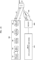
- FIG. 15 is a diagram illustrating an optical apparatus including a beam steering device 1000 according to an example embodiment.
- the optical apparatus of the example embodiment may be a LiDAR apparatus.
- the beam steering device 1000 of the optical apparatus may correspond to one of the beam steering devices D100, 1000, and 1100 of the previous example embodiments, or may be obtained by modifying the beam steering devices D100, 1000, and 1100.
- the beam steering device 1000 may have the configuration illustrated in FIG. 4 . That is, the beam steering device 1000 may include a light source unit 100, a multiplexer 200, an optical splitter 300, an optical modulator 400, and an emitter 500.
- the beam steering device 1000 may simultaneously emit a plurality of output lights L22 having different wavelengths toward an object OBJ.
- the output lights L22 may be emitted to different points arranged in a first direction DD1, simultaneously.
- the emission directions of the output lights L22 may be varied in a second direction DD2 different from the first direction DD1.
- the second direction DD2 may be perpendicular to the first direction DD1.
- the second direction DD2 may be referred to as a scanning direction.
- the optical apparatus may include a light receiver 2000 to receive the output lights L22 emitted from the beam steering device 1000 and reflected from the object OBJ, that is, to receive reflected light. Reflection may include general reflection and scattering. In addition, “reflection” may include variations (modulations) of light caused by the object OBJ.
- the light receiver 2000 may include a plurality of photo detecting elements, and the photo detecting elements may have an arrayed structure.
- the photo detecting elements may include photodiodes, phototransistors, and/or charge-coupled devices (CCDs).
- the optical apparatus may further include a demultiplexer (DEMUX) 1500 between the object OBJ and the light receiver 2000.
- the demultiplexer 1500 may demultiplex light reflected from the object OBJ to divide the light into a plurality of lights having different wavelengths (for example, ⁇ 1 , ⁇ 2 , ⁇ 3 , ..., and ⁇ n .
- the wavelengths (for example, ⁇ 1 , ⁇ 2 , ⁇ 3 , ..., and ⁇ n ) may respectively correspond to or may be respectively similar to the wavelengths (for example, ⁇ 1 , ⁇ 2 , ⁇ 3 , ..., and ⁇ n ) of the output lights L22 emitted from the beam steering device 1000.
- the optical apparatus may further include a circuit unit 3000 connected to either one or both of the beam steering device 1000 and the light receiver 2000.
- the circuit unit 3000 may include a calculating portion configured to acquire data and perform computation using the data.
- the circuit unit 3000 may further include a driver or a controller.
- the circuit unit 3000 may further include a power source unit and a memory.
- the configuration of the circuit unit 3000 may be variously modified according to the type of the optical apparatus.
- the circuit unit 3000 may be connected to a user interface UI.
- the optical apparatus of the example embodiment may use the light receiver 2000 to acquire information about a plurality of wavelengths from light reflected from the object OBJ and analyze information about the object OBJ, based on the acquired information.
- the light receiver 2000 includes a plurality of photo detecting elements
- the photo detecting elements may be used to obtain information about a plurality of wavelengths and analyze information about the object OBJ, based on the acquired information.
- Three-dimensional information about the object OBJ may be rapidly and precisely obtained by rapidly scanning the object OBJ in a two-dimensional manner, using a plurality of output lights L22 having different wavelengths.
- the optical apparatus illustrated in FIG. 15 may further include at least one optical element.
- the optical apparatus may further include a filter to detect light reflection points, according to wavelengths, and/or another optical element to control the intensity of light, according to wavelengths between the object OBJ and the light receiver 2000. An example of this is illustrated in FIG. 16 .
- FIG. 16 is a diagram illustrating an optical apparatus including a beam steering device 1000 according to another example embodiment.
- a filter 1700 may be provided between the demultiplexer 1500 and the light receiver 2000.
- Light may be divided into multiple wavelengths by the demultiplexer 1500, and light of a wavelength may reach a pixel of the light receiver 2000 through the filter 1700.
- the filter 1700 may be used to determine the position at which light of a wavelength is reflected from the object OBJ.
- At least one other optical element may be used instead of or together with the filter 1700 between the demultiplexer 1500 and the light receiver 2000.
- the at least one other optical element may include an optical element configured to control the intensity of reflected light according to the wavelengths of the reflected light. The intensity of reflected light may be controlled according to the wavelengths of the reflected light by using such an optical element.
- the optical apparatus of the example embodiment may further include a resonator or another optical element.
- FIG. 17 is a block diagram illustrating an overall systematic structure of an optical apparatus A1 including a beam steering device 1000A according to an example embodiment.
- the optical apparatus A1 may include the beam steering device 1000A.
- the beam steering device 1000A may correspond to or may be similar to the beam steering devices described with reference to FIGS. 1 , 2 , and 4 to 16.
- the optical apparatus A1 may include a light source unit provided as a part of or independently of the beam steering device 1000A.
- the optical apparatus A1 may include a detector 2000A to detect light steered by the beam steering device 1000A and reflected from an object.
- the detector 2000A may include the light receiver 2000 described with reference to FIG. 15 .
- the detector 2000A may further include the demultiplexer 1500 described with reference to FIG. 15 .
- the detector 2000A may further include the filter 1700 described with reference to FIG. 16 or another optical element.
- the optical apparatus A1 may further include a circuit unit 3000A connected to either one or both of the beam steering device 1000A and the detector 2000A.
- the circuit unit 3000A may include a calculating portion configured to acquire data and perform computation using the data.
- the circuit unit 3000A may further include a driver or a controller.
- the circuit unit 3000A may further include a power source unit and a memory.
- FIG. 17 illustrates that the optical apparatus A1 includes the beam steering device 1000A and the detector 2000A in a single device or apparatus.
- the beam steering device 1000A and the detector 2000A may be provided separately from each other in independent devices.
- the circuit 3000A may be connected to the beam steering device 1000A or the detector 2000A by a wireless communication method instead of a wired communication method.
- the configuration illustrated in FIG. 17 may be variously modified.
- the optical apparatuses of the example embodiments may be LiDAR apparatuses.
- the LiDAR apparatuses may be time-of-flight (TOF) or phase-shift type apparatuses.
- TOF time-of-flight
- the LiDAR apparatuses may be applied to autonomous vehicles, aircrafts such as drones, mobile devices, small vehicles (such as bicycles, motorcycles, babe carriages, or boards), robots, assistant devices or items for humans/animals (such as sticks, helmets, accessories, clothes, watches, or bags), Internet of Things (IoT) devices/systems, security devices/systems, etc.
- IoT Internet of Things
- the beam steering devices and the optical apparatuses including the beam steering devices according to the example embodiments are usable to obtain three-dimensional information about spaces and objects via two-dimensional scanning
- the beam steering devices and the optical apparatuses may be applied to three-dimensional image acquisition apparatuses or three-dimensional cameras.
- the beam steering devices and the optical apparatuses including the beam steering devices according to the example embodiments may be used for various purposes in a wide range of optical fields and electronic fields.
- the example embodiments described herein may be considered in a descriptive sense only and not for purposes of limitation.
- the structures of the beam steering devices are not limited to those illustrated in FIGS. 4 and 13 but may be variously modified as long as the beam steering devices are capable of scanning multiple points of an object using multiple wavelengths as described with reference to FIGS. 1 and 2 .
- the structures of the beam steering devices described with reference to FIGS. 4 to 13 and the structures of the optical apparatuses described with reference to FIGS. 15 to 17 can be variously modified.
- At least one wavelength variable laser source may be included in the beam steering devices, and the demultiplexer may be replaced with an equivalent or similar
- a one-dimensional scanning device a device performing a one-dimensional scanning operation using multi-wavelengths
- an optical apparatus including the one-dimensional scanning device may be implemented according to the example embodiments.
- the beam steering devices and the optical apparatuses may be applied in various other fields by various other application methods.
Landscapes
- Physics & Mathematics (AREA)
- Engineering & Computer Science (AREA)
- General Physics & Mathematics (AREA)
- Computer Networks & Wireless Communication (AREA)
- Radar, Positioning & Navigation (AREA)
- Remote Sensing (AREA)
- Optics & Photonics (AREA)
- Nonlinear Science (AREA)
- Electromagnetism (AREA)
- Semiconductor Lasers (AREA)
- Optical Modulation, Optical Deflection, Nonlinear Optics, Optical Demodulation, Optical Logic Elements (AREA)
- Optical Radar Systems And Details Thereof (AREA)
Abstract
Description
- Apparatuses consistent with example embodiments relate to optical devices and optical apparatuses, and more particularly, to beam steering devices and optical apparatuses including the beam steering devices.
- There has been increasing interest in techniques using light (beam) for measuring the distance to an object or the direction of an object, recognizing an object or the topography of an area, or detecting information about the velocity, temperature, material distribution, etc. of an object. In this regard, research has been conducted into methods for adjusting the direction of light (beam) generated by a light source, that is, methods of beam steering.
- Mechanical beam steering methods in which the direction of a beam is controlled by rotating some components, using a motor, have problems in terms of noise, size (volume), accuracy, etc. A typical non-mechanical beam steering method is a steering method using a micro-electro-mechanical system (MEMS) mirror. However, this method also has problems in terms of the field of view (FOV) and light transmitting distance.
- Therefore, there is a need for techniques for improving performance indexes such as accuracy, precision, or speed in analysis and measurement, using a non-mechanical beam steering method.
- Example embodiments may address at least the above problems and/or disadvantages and other disadvantages not described above. Also, the example embodiments are not required to overcome the disadvantages described above, and may not overcome any of the problems described above.
- Example embodiments provide beam steering devices configured to improve or increase the accuracy, precision, and speed of spatial analysis/measurement processes.
- Example embodiments provide beam steering devices capable of scanning objects (subjects) at high speed.
- Example embodiments provide beam steering devices capable of simultaneously emitting and steering a plurality of beams having multiple wavelengths.
- Example embodiments provide optical apparatuses (for example, LiDAR apparatuses) including the beam steering devices.
- According to an aspect of an example embodiment, there is provided a beam steering device including a light source configured to generate input lights having first different wavelengths, a multiplexer configured to simultaneously receive the generated input lights, and multiplex the received input lights into a multiplexed light, and an optical splitter configured to split the multiplexed light. The beam steering device further includes an optical modulator configured to modulate the split light, and an emitter configured to simultaneously emit output lights having second different wavelengths to different points arranged in a first direction, based on the modulated light.
- As the split light is further modulated, the emitted output lights may be moved in a second direction different from the first direction.
- The first direction may be perpendicular to the second direction.
- Either one or both of the emitter and the optical modulator may include waveguides, the first direction may be parallel to an extension direction of the waveguides, and the second direction may be perpendicular to the extension direction of the waveguides.
- Either one or both of the emitter and the optical modulator may include waveguides, and the first direction may be parallel to an extension direction of the waveguides.
- The optical modulator may include a phase modulator.
- The light source may include laser sources or a multimode laser source, wherein the laser sources or the multimode laser source may be configured to generate lasers having the first different wavelengths as the generated input lights.
- The light source may include a laser source configured to generate a laser having a wavelength, and a wavelength converter configured to divide the generated laser into lasers having the first different wavelengths as the generated input lights.
- The light source may include a light emitting diode (LED) configured to generate light, and a multi-band pass filter configured to divide the generated light into the generated input lights.
- Each of the generated input lights may have a pulse waveform.
- Any one or any combination of the optical splitter, the optical modulator, and the emitter may include any one or any combination of a group IV element, a compound including a group IV element, a group III-V compound, an oxide, a nitride, and a polymer.
- The beam steering device may further include an amplifier disposed between the multiplexer and the emitter, and having a semiconductor optical amplifier (SOA) structure.
- An optical apparatus may include the beam steering device, a light receiver configured to receive light that is emitted from the beam steering device and reflected from an object, and a circuit connected to either one or both of the beam steering device and the light receiver.
- The optical apparatus may further include a demultiplexer disposed between the object and the light receiver, and configured to demultiplex the reflected light, and divide the demultiplexed light into reflected lights having third different wavelengths, the light receiver may be further configured to receive the reflected lights.
- The light receiver may include photo detecting elements, and the optical apparatus may be configured to acquire information of the third different wavelengths of the reflected lights, using the photo detecting elements, and analyze information of the object, based on the acquired information.
- The optical apparatus may be a LiDAR apparatus.
- According to an aspect of another example embodiment, there is provided a beam steering device including an input coupler configured to simultaneously receive input lights having first different wavelengths, and an output coupler configured to simultaneously emit output lights having second different wavelengths to different points arranged in a first direction, and move the emitted output lights in a second direction different from the first direction, based on the received input lights.
- The beam steering device may further include waveguides disposed between the input coupler and the output coupler, the first direction may be parallel to an extension direction of the waveguides, and the second direction may be perpendicular to the extension direction of the waveguides.
- The beam steering device may further include an optical modulator disposed between the input coupler and the output coupler, and configured to move the emitted output lights in the second direction, based on the received input lights.
- The received input lights may include lasers having the first different wavelengths.
- The input coupler may include a multiplexer configured to simultaneously receive the input lights, and multiplex the received input lights.
- An optical apparatus may include the beam steering device, a light receiver configured to receive light that is emitted from the beam steering device and reflected from an object; and a circuit connected to either one or both of the beam steering device and the light receiver.
- The optical apparatus may further include a demultiplexer disposed between the object and the light receiver, and configured to demultiplex the reflected light, and divide the demultiplexed light into reflected lights having third different wavelengths, and the light receiver may be further configured to receive the reflected lights.
- The optical apparatus may be a LiDAR apparatus.
- According to an aspect of an example embodiment, there is provided a beam steering device including a multiplexer configured to simultaneously receive input lights having first different wavelengths, and multiplex the received input lights into a multiplexed light, and an optical splitter configured to split the multiplexed light. The beam steering apparatus further includes an optical modulator configured to modulate the split light, and an emitter configured to simultaneously emit output lights having second different wavelengths to different points arranged in a first direction and of an object, and move the emitted output lights in a second direction different from the first direction, based on the modulated light.
- The beam steering device may further include laser sources configured to generate lasers having the first different wavelengths, and input couplers configured to simultaneously receive the generated lasers, and transmit the received lasers to the multiplexer as the input lights.
- Either one or both of the emitter and the optical modulator may include a substrate, an insulative layer disposed on the substrate, and waveguides disposed on the insulative layer. The first direction may be parallel to an extension direction of the waveguides, and the second direction may be perpendicular to the extension direction of the waveguides.
- The beam steering device may further include a cover layer disposed on the multiplexer, the optical splitter, the optical modulator, and the emitter.
- An optical apparatus may include the beam steering device, and a demultiplexer configured to receive light that is reflected from the object, demultiplex the reflected light, and divide the demultiplexed light into reflected lights having third different wavelengths. The optical apparatus may further include a filter configured to filter the reflected lights, and a light receiver configured to receive the filtered reflected lights.
- The above and/or other aspects will become apparent and more readily appreciated from the following description of example embodiments, taken in conjunction with the accompanying drawings in which:
-
FIGS. 1 and2 are schematic views illustrating a beam steering device according to an example embodiment; -
FIG. 3 is a schematic view illustrating a beam steering device according to a comparative example; -
FIG. 4 is a block diagram illustrating an example configuration of the beam steering device depicted inFIG. 1 ; -
FIG. 5 is a block diagram illustrating a light source unit and an input unit applicable to a beam steering device according to an example embodiment; -
FIG. 6 is a block diagram illustrating a light source unit and an input unit applicable to a beam steering device according to another example embodiment; -
FIG. 7 is a block diagram illustrating a light source unit and an input unit applicable to a beam steering device according to another example embodiment; -
FIG. 8 is a block diagram illustrating a light source unit and an input unit applicable to a beam steering device according to another example embodiment; -
FIG. 9 is a plan view illustrating light split by an optical splitter applicable to a beam steering device according to an example embodiment; -
FIG. 10 is a plan view illustrating light modulation by an optical modulator applicable to a beam steering device according to an example embodiment; -
FIG. 11 is a perspective view illustrating a relationship between a steering direction and waveguides applicable to a beam steering device according to an example embodiment; -
FIG. 12 is a cross-sectional view schematically illustrating a beam steering device provided in the form of a single device (semiconductor device), according to an example embodiment; -
FIG. 13 is a block diagram illustrating an example configuration of a beam steering device according to another example embodiment; -
FIG. 14 is a graph illustrating a light type as an example of light applicable to a beam steering device according to an example embodiment; -
FIG. 15 is a diagram illustrating an optical apparatus including a beam steering device according to an example embodiment; -
FIG. 16 is a diagram illustrating an optical apparatus including a beam steering device according to another example embodiment; and -
FIG. 17 is a block diagram illustrating an overall systematic structure of an optical apparatus including a beam steering device according to an example embodiment. - Example embodiments are described in greater detail below with reference to the accompanying drawings.
- In the following description, like drawing reference numerals are used for like elements, even in different drawings. The matters defined in the description, such as detailed construction and elements, are provided to assist in a comprehensive understanding of the example embodiments. However, it is apparent that the example embodiments can be practiced without those specifically defined matters. Also, well-known functions or constructions may not be described in detail because they would obscure the description with unnecessary detail.
- As used herein, the term "and/or" includes any and all combinations of one or more of the associated listed items. Expressions such as "at least one of," when preceding a list of elements, modify the entire list of elements and do not modify the individual elements of the list.
- It will be understood that when an element is referred to as being "connected" or "coupled" to another element, it can be directly connected or coupled to the other element or intervening elements may be present. In contrast, when an element is referred to as being "directly connected" or "directly coupled" to another element, there are no intervening elements present. As used herein the term "and/or" includes any and all combinations of one or more of the associated listed items.
- It will be understood that, although the terms "first," "second," etc. may be used herein to describe various elements, components, regions, layers and/or sections, these elements, components, regions, layers and/or sections may not be limited by these terms. These terms are only used to distinguish one element, component, region, layer or section from another element, component, region, layer or section. Thus, a first element, component, region, layer or section discussed below could be termed a second element, component, region, layer or section without departing from the teachings of example embodiments.
- Spatially relative terms, such as "beneath," "below," "lower," "above," "upper" and the like, may be used herein for ease of description to describe one element or feature's relationship to another element(s) or feature(s) as illustrated in the figures. It will be understood that the spatially relative terms are intended to encompass different orientations of the device in use or operation in addition to the orientation depicted in the figures. For example, if the device in the figures is turned over, elements described as "below" or "beneath" other elements or features would then be oriented "above" the other elements or features. Thus, the term "below" can encompass both an orientation of above and below. The device may be otherwise oriented (rotated 90 degrees or at other orientations) and the spatially relative descriptors used herein interpreted accordingly.
- The terminology used herein is for the purpose of describing example embodiments only and is not intended to be limiting of example embodiments. As used herein, the singular forms "a," "an" and "the" are intended to include the plural forms as well, unless the context clearly indicates otherwise. It will be further understood that the terms "comprises" and/or "comprising," when used in this specification, specify the presence of stated features, integers, steps, operations, elements, and/or components, but do not preclude the presence or addition of one or more other features, integers, steps, operations, elements, components, and/or groups thereof.
- Example embodiments are described herein with reference to cross-sectional illustrations that are schematic illustrations of idealized embodiments (and intermediate structures) of example embodiments. As such, variations from the shapes of the illustrations as a result, for example, of manufacturing techniques and/or tolerances, are to be expected. Thus, example embodiments may not be construed as limited to the shapes of regions illustrated herein but are to include deviations in shapes that result, for example, from manufacturing. For example, an implanted region illustrated as a rectangle will have rounded or curved features and/or a gradient of implant concentration at its edges rather than a binary change from implanted to non-implanted region. Likewise, a buried region formed by implantation may result in some implantation in the region between the buried region and the surface through which the implantation takes place. Thus, the regions illustrated in the figures are schematic in nature and their shapes are not intended to illustrate the actual shape of a region of a device and are not intended to limit the scope of example embodiments.
- Unless otherwise defined, all terms (including technical and scientific terms) used herein have the same meaning as commonly understood by one of ordinary skill in the art to which example embodiments belong. It will be further understood that terms, such as those defined in commonly-used dictionaries, may be interpreted as having a meaning that is consistent with their meaning in the context of the relevant art and will not be interpreted in an idealized or overly formal sense unless expressly so defined herein.
- Hereinafter, beam steering devices and optical apparatuses including the beam steering devices will be described according to example embodiments with reference to the accompanying drawings. In the drawings, the widths and thicknesses of layers or regions may be exaggerated for clarity or ease of description.
-
FIGS. 1 and2 are schematic views illustrating a beam steering device D100 according to an example embodiment. - Referring to
FIG. 1 , the beam steering device D100 may include an input coupler IN10 and an output coupler OUT10. A plurality of lights (beams) L10 having different wavelengths may be simultaneously input through the input coupler IN10. In other words, multi-wavelength (multi-λ) light L10 may be input through the input coupler IN10. - A plurality of output lights (beams) L20 having different wavelengths may be simultaneously emitted toward an object OBJ through the output coupler OUT10. The plurality of output lights L20 may be simultaneously emitted to different points arranged in a first direction DD1. The points toward which the output lights L20 are emitted may be one-dimensionally arranged. In other words, the output lights L20 may be simultaneously emitted toward a plurality of points that are one-dimensionally arranged in a line. The wavelengths of the output lights L20 may include a first wavelength λ1, a second wavelength λ2, a third wavelength λ3, a fourth wavelength λ4, etc. However, this is an example. That is, the number of the wavelengths of the output lights L20 may vary.
- The illustrated structure of the object OBJ is an example. That is, the object OBJ may have a different structure, size, etc. The object OBJ is not limited to a type. For example, the object OBJ may be a space or anything existing in a space.
- According to the example embodiment, the beam steering device D100 may simultaneously emit the plurality of output lights L20 having different wavelengths to detect/search a plurality of points in the first direction DD1. In addition, the beam steering device D100 may vary (change) the emission directions of the output lights L20 in a direction different from the first direction DD1. This will now be described with reference to
FIG. 2 . - Referring to
FIG. 2 , the beam steering device D100 may be configured to change the emission directions of the output lights L20 in a second direction DD2 different from the first direction DD1. For example, the second direction DD2 may be perpendicular to the first direction DD1. The emission directions of the output lights L20 may be varied in the second direction DD2 by optical modulation performed in the beam steering device D100. The emission directions of the output lights L20 having different wavelengths (for example, wavelengths λ1 to λ4) may vary with time in the second direction DD2 as a result of the optical modulation. Thus, the second direction DD2 may be referred to as a "scanning direction." - According to the example embodiment, the beam steering device D100 may perform a scanning operation while changing the emission directions of the output lights L20 in the second direction DD2. Therefore, the beam steering device D100 may perform a two-dimensional scanning operation at a relatively high speed compared to point-by-point beam steering devices.
-
FIG. 3 is a schematic view illustrating a beam steering device D10 according to a comparative example. - Referring to
FIG. 3 , the beam steering device D10 of the comparative example may perform a point-by-point scanning operation. For example, the beam steering device D10 of the comparative example may scan an object OBJ while moving an output light (beam) having a single wavelength λ1 in a scanning direction. The output light having a single wavelength λ1 may be emitted to a first point at a first time point T1, a second point at a second time point T2, a third point at a third time point T3, a fourth point at a fourth time point T4, and a fifth point at a fifth time point T5. Thus, it may be considered that the beam steering device D10 performs a one-dimensional scanning operation. Complex and difficult techniques may be used to perform a two-dimensional scanning operation, using the beam steering device D10. In addition, because such a one-dimensional or two-dimensional scanning operation is performed basically by using a point-by-point method, the speed, accuracy, and precision of the scanning operation may be low. For example, because the first point is detected at the first time point T1 and the fifth point is detected at the fifth time point T5, the accuracy and precision of detection may be low because of a detection time difference. The accuracy and precision of detection/analysis may be decreased as the speed of scanning is decreased. - However, if the beam steering device D100 of the example embodiment is used, a two-dimensional scanning operation may be performed at a high speed by simultaneously emitting the plurality of output lights L20 having different wavelengths. Thus, the speed of detection/analysis may be increased, and the accuracy and precision of detection/analysis may be markedly improved.
-
FIG. 4 is a block diagram illustrating an example configuration of the beam steering device D100 depicted inFIG. 1 . InFIG. 4 , the beam steering device D100 is indicated using areference numeral 1000. - Referring to
FIG. 4 , alight source unit 100 may generate a plurality of lights L11 having different wavelengths. The plurality of lights L11 may be referred to as multi-wavelength (multi-λ) electromagnetic waves. For example, the plurality of lights L11 may be a plurality of lasers (laser beams) having different wavelengths. However, the plurality of lights L11 may be another kind of light other than a laser. Thelight source unit 100 may generate the plurality of lights L11 at the same time. - A multiplexer (MUX) 200 may simultaneously receive and multiplex the plurality of lights L11 generated by the
light source unit 100. Themultiplexer 200 may have a general optical multiplexer structure. In addition, themultiplexer 200 may also function as an input coupler. - An
optical splitter 300 may split the light multiplexed by themultiplexer 200. Theoptical splitter 300 may be a beam splitter. Each of lights (beams) split by theoptical splitter 300 may have multiple wavelengths (multi-λ). - An
optical modulator 400 may modulate the multiplexed light split by theoptical splitter 300. Theoptical modulator 400 may modulate light by various methods. For example, theoptical modulator 400 may modulate the phase of the light split by theoptical splitter 300. Alternatively, theoptical modulator 400 may modulate the amplitude of the light split by theoptical splitter 300. Alternatively, theoptical modulator 400 may modulate both the phase and amplitude of the light split by theoptical splitter 300. In addition to this, theoptical modulator 400 may have other optical modulation functions. Theoptical modulator 400 may perform optical modulation by using a method such as an electric method, a magnetic method, a thermal method, or a mechanical method. For example, theoptical modulator 400 may include at least one phase shifter (or phase shifting element), and the phase shifter may include at least one selected from the group consisting of a gain element, an all-pass filter, a Bragg grating, a dispersive material element, a wavelength tuning element, and a phase tuning element. In addition, an actuation mechanism of theoptical modulator 400 may include at least one selected from the group consisting of a thermo-optic actuation mechanism, an electro-optic actuation mechanism, an electroabsorption actuation mechanism, a free carrier absorption actuation mechanism, a magneto-optic actuation mechanism, a liquid crystal actuation mechanism, and an all-optical actuation mechanism. The actuation mechanism of theoptical modulator 400 may be related to the above-described phase tuning. The phase shifter and the actuation mechanism of theoptical modulator 400 of the example embodiment are not limited to the above examples. - An emitting portion (emitter) 500 may receive light from the
optical modulator 400 and may simultaneously emit a plurality of output lights L22. The output lights L22 may have different wavelengths (for example, wavelengths λ1, λ2, λ3, ..., and λn). The plurality of output lights L22 may be emitted to different points arranged in a first direction DD1. The wavelengths of the output lights L22 may correspond to or may be similar to the wavelengths of the lights L11 generated by thelight source unit 100. The output lights L22 may correspond to the output lights L20 described with reference toFIG. 1 . - Due to the optical modulation by the
optical modulator 400, the emission directions of the output lights L22 may be varied in a second direction DD2 different from the first direction DD1. For example, as theoptical modulator 400 performs a modulation operation such as a phase modulation operation on light (split lights), the emission directions of the output lights L22 may be varied in the second direction DD2. For example, the second direction DD2 may be perpendicular to the first direction DD1. The first direction DD1 and the second direction DD2 may correspond to the first direction DD1 and the second direction DD2 described with reference toFIG. 2 . Thus, the second direction DD2 may be referred to as a scanning direction. - The
emitter 500 may be an output coupler. For example, theemitter 500 may include a plurality of waveguides. In addition, theemitter 500 may further include grating structures formed on the waveguides. The grating structures may be designed to direct a beam having a wavelength in a direction. However, the configuration of theemitter 500 is not limited thereto. That is, the configuration of theemitter 500 may be variously modified. - In the example embodiment, the
beam steering device 1000 may include themultiplexer 200, theoptical splitter 300, theoptical modulator 400, and theemitter 500. In this case, themultiplexer 200 may be an input coupler, and theemitter 500 may be an output coupler. Themultiplexer 200, theoptical splitter 300, theoptical modulator 400, and theemitter 500 may form a single device (an optical semiconductor device), and thelight source unit 100 may be provided separately from the single device and may emit a plurality of lights L11 toward themultiplexer 200. In a broad sense, however, thelight source unit 100 may be considered as a part of thebeam steering device 1000. That is, it may be considered that thebeam steering device 1000 includes thelight source unit 100, themultiplexer 200, theoptical splitter 300, theoptical modulator 400, and theemitter 500. That is, themultiplexer 200, theoptical splitter 300, theoptical modulator 400, and theemitter 500 may be provided on a single chip, or thelight source unit 100, themultiplexer 200, theoptical splitter 300, theoptical modulator 400, and theemitter 500 may be provided on a single chip. - Hereinafter, the configurations of light source units and input units (input couplers) applicable to beam steering devices will be described with reference to
FIGS. 5 to 8 . -
FIG. 5 is a block diagram illustrating a light source unit and an input unit applicable to a beam steering device according to an example embodiment. - Referring to
FIG. 5 , in the example embodiment, alight source unit 110 may include a plurality of laser sources LD1 to LD4. Although four laser sources LD1 to LD4 are illustrated, the number of the laser sources may vary. The laser sources LD1 to LD4 may be laser diodes. The laser sources LD1 to LD4 may generate a plurality of lasers (laser beams) having different wavelengths (for example, wavelengths λ01, λ02, λ03, and λ04). The plurality of lasers having different wavelengths λ01, λ02, λ03, and λ04 that are generated by the laser sources LD1 to LD4 may be input to amultiplexer 200 and may be multiplexed. In this case, themultiplexer 200 may be considered as an input coupler (input unit). The light multiplexed by themultiplexer 200 may be split by anoptical splitter 300. A configuration after theoptical splitter 300 may be substantially the same as or similar to that described with reference toFIG. 4 . According to another example embodiment, a multimode laser source may be used instead of the plurality of laser sources LD1 to LD4. In this case, the multimode laser source may generate a plurality of lasers (laser beams) having different wavelengths. -
FIG. 6 is a block diagram illustrating a light source unit and an input unit applicable to a beam steering device according to another example embodiment. - Referring to
FIG. 6 , lasers having different wavelengths λ01, λ02, λ03, and λ04 that are generated by laser sources LD1 to LD4 may be input to different input couplers IN1 to IN4, respectively. The input couplers IN1 to IN4 may constitute an "input unit 150." For example, the input couplers IN1 to IN4 may have an optical fiber structure or another structure. After passing through the input couplers IN1 to IN4, the plurality of lights may be multiplexed by amultiplexer 200 and may then be split by anoptical splitter 300. A configuration after theoptical splitter 300 may be substantially the same as or similar to that described with reference toFIG. 4 . - The input couplers IN1 to IN4 and the
multiplexer 200 illustrated inFIG. 6 may be connected to each other by an optical waveguide. In some cases, the combination of the input couplers IN1 to IN4 and themultiplexer 200 may be considered as an "input unit." -
FIG. 7 is a block diagram illustrating a light source unit and an input unit applicable to a beam steering device according to another example embodiment. - Referring to
FIG. 7 , alight source unit 120 may include a laser source LD10 configured to generate a laser having a single wavelength λ0. That is, thelight source unit 120 may be constituted by a single laser source LD10. Awavelength converter 160 may divide the laser generated by the laser source LD10 into a plurality of lasers having different wavelengths (for example, wavelengths λ01, λ02, λ03, and λ04). For example, thewavelength converter 160 may include an input coupler, an optical divider, and a plurality of wavelength converting elements. A laser input to the input coupler may be divided by the optical divider, and the wavelength of the divided laser may be converted by the wavelength converting elements. As a result, a plurality of lights having different wavelengths (for example, wavelengths λ01, λ02, λ03, and λ04) may be output from thewavelength converter 160. Then, the lights may be multiplexed by amultiplexer 200 and may then be split by anoptical splitter 300. A configuration after theoptical splitter 300 may be equal or similar to that described with reference toFIG. 4 . The above-described configuration of thewavelength converter 160 is an example. That is, the configuration of thewavelength converter 160 may be variously modified. - The combination of the laser source LD10 and the
wavelength converter 160 illustrated inFIG. 7 may be considered as a "light source unit." That is, it may be considered that such a light source unit generates a plurality of lights having different wavelengths (for example, wavelengths λ01, λ02, λ03, and λ04). In addition, at least a portion of thewavelength converter 160 or at least a portion of themultiplexer 200 may be considered as an "input coupler." Alternatively, the combination of thewavelength converter 160 and themultiplexer 200 may be considered as an input coupler. -
FIG. 8 is a block diagram illustrating a light source unit and an input unit applicable to a beam steering device according to another example embodiment. - Referring to
FIG. 8 , alight source unit 130 may include a light emitting diode (LED). For example, the LED may be a white LED. In other words, the LED may be a device capable of emitting a wideband light. Amulti-band pass filter 170 may divide the light generated by thelight source unit 130. A plurality of lights having a plurality of wavelengths (for example, wavelengths λ11, λ12, λ13, and λ14) may be output through themulti-band pass filter 170. Then, the plurality of lights may be multiplexed by amultiplexer 200 and may then be split by anoptical splitter 300. A configuration after theoptical splitter 300 may be equal or similar to that described with reference toFIG. 4 . - The combination of the LED (that is, the light source unit 130) and the
multi-band pass filter 170 illustrated inFIG. 8 may be considered as a "light source unit." It may be considered that such a light source unit generates a plurality of lights having different wavelengths. In the example embodiment, themultiplexer 200 may be considered as an "input coupler." -
FIG. 9 is a plan view illustrating light split by anoptical splitter 300A applicable to a beam steering device according to an example embodiment. - Referring to
FIG. 9 , a light multiplexed by a multiplexer (such as themultiplexer 200 illustrated inFIG. 4 ) may be input to theoptical splitter 300A and may be split by theoptical splitter 300A. The split lights may be output (may propagate) through a plurality of optical path elements W10. The optical path elements W10 may be waveguides. For example, the optical path elements W10 may include first to eighth optical path elements w11 to w18. The first to eighth optical path elements w11 to w18 are examples. That is, the number of the optical path elements W10 may vary. Light output (propagating) through each of the first to eighth optical path elements w11 to w18 may have multiple wavelengths. The light output (propagating) through each of the first to eighth optical path elements w11 to w18 may include lights having wavelengths λ01, λ02, λ03, and λ04 illustrated inFIG. 5 , for example. Theoptical splitter 300A may have a multimode interference (MMI) structure or another structure. In addition, theoptical splitter 300A may use a multi-step beam splitting structure to increase the number of split beams. The structure of theoptical splitter 300A may be variously modified. -
FIG. 10 is a plan view illustrating light modulation by anoptical modulator 400A applicable to a beam steering device according to an example embodiment. - Referring to
FIG. 10 , theoptical modulator 400A may be placed on a plurality of optical path elements W10. Theoptical modulator 400A may be placed above or below the optical path elements W10. It may be considered that the optical path elements W10 are included in theoptical modulator 400A. The optical path elements W10 may be those extending from the optical path elements W10 described with reference toFIG. 9 . For example, the optical path elements W10 may include first to eighth optical path elements w11 to w18. However, the number of the optical path elements W10 is not limited thereto. Theoptical modulator 400A may modulate lights propagating through the optical path elements W10. Theoptical modulator 400A may modulate lights propagating through the first to eighth optical path elements w11 to w18. For example, a light propagating through the first optical path element w11 may be modulated to a first degree, a light propagating through the second optical path element w12 may be modulated to a second degree, a light propagating through the third optical path element w13 may be modulated to a third degree, a light propagating through the fourth optical path element w14 may be modulated to a fourth degree, a light propagating through the fifth optical path element w15 may be modulated to a fifth degree, a light propagating through the sixth optical path element w16 may be modulated to a sixth degree, a light propagating through the seventh optical path element w17 may be modulated to a seventh degree, and a light propagating through the eighth optical path element w18 may be modulated to an eighth degree. In other words, lights propagating through the first to eighth optical path elements w11 to w18 may be modulated to different degrees. As a result, the wavefronts of lights output from the first to eighth optical path elements w11 to w18 may be adjusted to control the directions of the output lights (beams). For example, the emission direction of the output light may be varied in a direction such as a second direction DD2 owing to optical modulation performed by theoptical modulator 400A. - The structure and operational mechanism of the
optical modulator 400A may be variously modified. For example, theoptical modulator 400A may be configured to perform phase modulation, amplitude modulation, or phase-amplitude modulation. In addition, theoptical modulator 400A may perform optical modulation by using a method such as an electric method, a magnetic method, a thermal method, or a mechanical method. In addition, for example, the structure, size, and number of the optical path elements W10 illustrated inFIG. 10 may be variously modified. -
FIG. 11 is a perspective view illustrating a relationship between a steering direction and waveguides applicable to a beam steering device according to an example embodiment. - Referring to
FIG. 11 , the beam steering device may include a plurality of waveguides W1 formed on a substrate SUB1. An insulative layer N1 may be provided on the substrate SUB1, and the waveguides W1 may be arranged on the insulative layer N1. The insulative layer N1 is optional. That is, the insulative layer N1 may not be included in example embodiments. The waveguides W1 may extend in a direction. The waveguides W1 may be arranged in parallel with each other. - The plurality of waveguides W1 may be included in the output coupler OUT10 or the
emitter 500 illustrated with reference toFIG. 1 or4 . In other words, the output coupler OUT10 and theemitter 500 may include the plurality of waveguides W1. Each of the waveguides W1 may have a grating structure. The characteristics or directions of lights (beams) output from the waveguides W1 may vary according to the shapes, sizes, or pattern intervals of the grating structures of the waveguides W1. Thus, the waveguides W1 may be considered as a grating coupler. In example embodiments, theoptical modulator 400 illustrated inFIG. 4 may include the plurality of waveguides W1. In this case, theoptical modulator 400 may modulate lights propagating through the plurality of waveguides W1. - For example, the first direction DD1 described with reference to
FIGS. 1 and2 may be parallel to an extension direction of the waveguides W1 illustrated inFIG. 11 , and the second direction DD2 may be perpendicular to the extension direction of the waveguides W1 illustrated inFIG. 11 . In other words, a plurality of output lights (refer to the output lights L20 illustrated inFIG. 1 ) may spread in a direction parallel to the extension direction of the waveguides W1, and as a result of the optical modulation, the emission directions of the output lights (refer to the output lights L20 illustrated inFIG. 1 ) may be varied in a direction perpendicular to the extension direction of the waveguides W1. - The structure and extension direction of the waveguides W1 illustrated in
FIG. 11 are examples. That is, the structure and extension direction of the waveguides W1 may be variously modified. In addition, the relationship between the extension direction of the waveguides W1 and a steering direction is not limited to the description presented above. -
FIG. 12 is a cross-sectional view schematically illustrating a beam steering device provided in the form of a single device (semiconductor device), according to an example embodiment. - Referring to
FIG. 12 , the beam steering device may include an input coupler E10 and an output coupler E40 that are arranged on a substrate SUB10. In addition, the beam steering device may further include an optical splitter E20 and an optical modulator E30 that are arranged between the input coupler E10 and the output coupler E40. An insulative layer N10 may be optionally provided on the substrate SUB10, and the input coupler E10, the optical splitter E20, the optical modulator E30, and the output coupler E40 may be arranged on the insulative layer N10. Optical waveguide(s) may be provided between two neighboring elements, that is, between the input coupler E10 and the optical splitter E20, between the optical splitter E20 and the optical modulator E30, and between the optical modulator E30 and the output coupler E40. - The input coupler E10 may be configured to receive a plurality of lights having different wavelengths. To this end, the input coupler E10 may include a multiplexer. For example, the optical splitter E20 may have a multimode interference (MMI) structure or another structure. The optical modulator E30 may perform an optical modulation operation by using an electric method or another method such as a magnetic method, a thermal method, or a mechanical method. In addition, the optical modulator E30 may use various modulation methods such as a phase modulation method or an amplitude modulation method. The optical modulator E30 may include a plurality of waveguides and may modulate beams propagating through the waveguides. For example, the output coupler E40 may include a plurality of waveguides and grating structures respectively formed on the waveguides. The structures of the input coupler E10, the optical splitter E20, the optical modulator and the output coupler E40 are not limited to those described above and may be variously modified.
- A cover layer C10 may be further provided on the substrate SUB10 to cover the input coupler E10, the optical splitter E20, the optical modulator E30, and the output coupler E40. The cover layer C10 may include a low refractive material having a relatively low refractive index. For example, the cover layer C10 may include a dielectric material such as a silicon oxide or a polymer-based material. The cover layer C10 may also function as a protective layer. However, the cover layer C10 may not be provided in example embodiments.
- Any one or any combination of the input coupler E10, the optical splitter E20, the optical modulator E30, and the output coupler E40 may include: any one or any combination of a group IV element such as silicon (Si) or germanium (Ge); a compound containing a group IV element such as SiGe; a group III-V compound; an oxide; a nitride; and a polymer. In example embodiments, at least two of the input coupler E10, the optical splitter E20, the optical modulator E30, and the output coupler E40 may include different materials. If the substrate SUB10 includes silicon (Si), or any one or any combination of the input coupler E10, the optical splitter E20, the optical modulator E30, and the output coupler E40 includes silicon (Si), the beam steering device of the example embodiment may be implemented/manufactured using a silicon photonics technique. Because the silicon photonics technique is used in (that is, compatible with) a complementary metal oxide semiconductor (CMOS) process, the silicon photonics technique may make it easy to perform manufacturing processes.
-
FIG. 13 is a block diagram illustrating an example configuration of abeam steering device 1100 according to another example embodiment. Thebeam steering device 1100 of the current example embodiment is a modification of thebeam steering device 1000 illustrated inFIG. 4 . - Referring to
FIG. 13 , thebeam steering device 1100 may further include anamplifier 450 between amultiplexer 200 and anemitter 500. For example, theamplifier 450 may be placed between anoptical modulator 400 and theemitter 500. Theamplifier 450 may have a semiconductor optical amplifier (SOA) structure, for example. Theamplifier 450 may amplify optical signals so that the intensity of lights generated by alight source unit 100 may be maintained at theemitter 500. Alternatively, theamplifier 450 may increase a signal-to-noise ratio (SNR). The position and configuration of theamplifier 450 described with reference toFIG. 13 are examples. That is, the position and configuration of theamplifier 450 may vary. -
FIG. 14 is a graph illustrating a light type as an example of light applicable to a beam steering device according to an example embodiment. - Referring to
FIG. 14 , the light generated by a light source unit of the beam steering device may have a pulse waveform. For example, if the light source unit generates a laser, the laser may be a pulsed laser. Thus, ON and OFF states of the light may be alternately repeated, and in the ON state, light having a wavelength (or wavelength band) may be generated as shown in an enlarged section on the right side ofFIG. 14 . For example, the wavelength of the light may correspond to one of wavelengths λ01, λ02, λ03, and λ04 shown inFIG. 5 . A pulse wave (for example, a pulsed laser) is different from a continuous wave (CW) or a CW laser. The CW laser may be used for the Doppler effect, and the pulse wave (for example, pulsed laser) may be used for other purposes and effects. However, the type of light used according to example embodiments is not limited to the type described with reference toFIG. 14 . That is, the type of light may vary according to example embodiments. - The above-described beam steering devices of the example embodiments may be applied to various optical apparatuses. For example, the beam steering devices may be applied to light detection and ranging (LiDAR) apparatuses.
-
FIG. 15 is a diagram illustrating an optical apparatus including abeam steering device 1000 according to an example embodiment. The optical apparatus of the example embodiment may be a LiDAR apparatus. - Referring to
FIG. 15 , thebeam steering device 1000 of the optical apparatus may correspond to one of the beam steering devices D100, 1000, and 1100 of the previous example embodiments, or may be obtained by modifying the beam steering devices D100, 1000, and 1100. In the current example embodiment, thebeam steering device 1000 may have the configuration illustrated inFIG. 4 . That is, thebeam steering device 1000 may include alight source unit 100, amultiplexer 200, anoptical splitter 300, anoptical modulator 400, and anemitter 500. Thebeam steering device 1000 may simultaneously emit a plurality of output lights L22 having different wavelengths toward an object OBJ. The output lights L22 may be emitted to different points arranged in a first direction DD1, simultaneously. The emission directions of the output lights L22 may be varied in a second direction DD2 different from the first direction DD1. The second direction DD2 may be perpendicular to the first direction DD1. The second direction DD2 may be referred to as a scanning direction. - The optical apparatus may include a
light receiver 2000 to receive the output lights L22 emitted from thebeam steering device 1000 and reflected from the object OBJ, that is, to receive reflected light. Reflection may include general reflection and scattering. In addition, "reflection" may include variations (modulations) of light caused by the object OBJ. Thelight receiver 2000 may include a plurality of photo detecting elements, and the photo detecting elements may have an arrayed structure. For example, the photo detecting elements may include photodiodes, phototransistors, and/or charge-coupled devices (CCDs). - The optical apparatus may further include a demultiplexer (DEMUX) 1500 between the object OBJ and the
light receiver 2000. Thedemultiplexer 1500 may demultiplex light reflected from the object OBJ to divide the light into a plurality of lights having different wavelengths (for example, λ1, λ2, λ3, ..., and λn. The wavelengths (for example, λ1, λ2, λ3, ..., and λn) may respectively correspond to or may be respectively similar to the wavelengths (for example, λ1, λ2, λ3, ..., and λn) of the output lights L22 emitted from thebeam steering device 1000. - In addition, the optical apparatus may further include a
circuit unit 3000 connected to either one or both of thebeam steering device 1000 and thelight receiver 2000. Thecircuit unit 3000 may include a calculating portion configured to acquire data and perform computation using the data. Thecircuit unit 3000 may further include a driver or a controller. In addition, thecircuit unit 3000 may further include a power source unit and a memory. The configuration of thecircuit unit 3000 may be variously modified according to the type of the optical apparatus. Thecircuit unit 3000 may be connected to a user interface UI. - The optical apparatus of the example embodiment may use the
light receiver 2000 to acquire information about a plurality of wavelengths from light reflected from the object OBJ and analyze information about the object OBJ, based on the acquired information. If thelight receiver 2000 includes a plurality of photo detecting elements, the photo detecting elements may be used to obtain information about a plurality of wavelengths and analyze information about the object OBJ, based on the acquired information. Three-dimensional information about the object OBJ may be rapidly and precisely obtained by rapidly scanning the object OBJ in a two-dimensional manner, using a plurality of output lights L22 having different wavelengths. - In example embodiments, the optical apparatus illustrated in
FIG. 15 may further include at least one optical element. For example, the optical apparatus may further include a filter to detect light reflection points, according to wavelengths, and/or another optical element to control the intensity of light, according to wavelengths between the object OBJ and thelight receiver 2000. An example of this is illustrated inFIG. 16 . -
FIG. 16 is a diagram illustrating an optical apparatus including abeam steering device 1000 according to another example embodiment. - Referring to
FIG. 16 , afilter 1700 may be provided between thedemultiplexer 1500 and thelight receiver 2000. Light may be divided into multiple wavelengths by thedemultiplexer 1500, and light of a wavelength may reach a pixel of thelight receiver 2000 through thefilter 1700. Thus, thefilter 1700 may be used to determine the position at which light of a wavelength is reflected from the object OBJ. At least one other optical element may be used instead of or together with thefilter 1700 between thedemultiplexer 1500 and thelight receiver 2000. For example, the at least one other optical element may include an optical element configured to control the intensity of reflected light according to the wavelengths of the reflected light. The intensity of reflected light may be controlled according to the wavelengths of the reflected light by using such an optical element. In addition, the optical apparatus of the example embodiment may further include a resonator or another optical element. -
FIG. 17 is a block diagram illustrating an overall systematic structure of an optical apparatus A1 including abeam steering device 1000A according to an example embodiment. - Referring to
FIG. 17 , the optical apparatus A1 may include thebeam steering device 1000A. Thebeam steering device 1000A may correspond to or may be similar to the beam steering devices described with reference toFIGS. 1 ,2 , and4 to 16. The optical apparatus A1 may include a light source unit provided as a part of or independently of thebeam steering device 1000A. - The optical apparatus A1 may include a
detector 2000A to detect light steered by thebeam steering device 1000A and reflected from an object. Thedetector 2000A may include thelight receiver 2000 described with reference toFIG. 15 . In addition, thedetector 2000A may further include thedemultiplexer 1500 described with reference toFIG. 15 . In addition, thedetector 2000A may further include thefilter 1700 described with reference toFIG. 16 or another optical element. - In addition, the optical apparatus A1 may further include a
circuit unit 3000A connected to either one or both of thebeam steering device 1000A and thedetector 2000A. Thecircuit unit 3000A may include a calculating portion configured to acquire data and perform computation using the data. Thecircuit unit 3000A may further include a driver or a controller. In addition, thecircuit unit 3000A may further include a power source unit and a memory. -
FIG. 17 illustrates that the optical apparatus A1 includes thebeam steering device 1000A and thedetector 2000A in a single device or apparatus. However, thebeam steering device 1000A and thedetector 2000A may be provided separately from each other in independent devices. In addition, thecircuit 3000A may be connected to thebeam steering device 1000A or thedetector 2000A by a wireless communication method instead of a wired communication method. The configuration illustrated inFIG. 17 may be variously modified. - The optical apparatuses of the example embodiments may be LiDAR apparatuses. The LiDAR apparatuses may be time-of-flight (TOF) or phase-shift type apparatuses. The LiDAR apparatuses may be applied to autonomous vehicles, aircrafts such as drones, mobile devices, small vehicles (such as bicycles, motorcycles, babe carriages, or boards), robots, assistant devices or items for humans/animals (such as sticks, helmets, accessories, clothes, watches, or bags), Internet of Things (IoT) devices/systems, security devices/systems, etc. Because the beam steering devices and the optical apparatuses including the beam steering devices according to the example embodiments are usable to obtain three-dimensional information about spaces and objects via two-dimensional scanning, the beam steering devices and the optical apparatuses may be applied to three-dimensional image acquisition apparatuses or three-dimensional cameras. In addition, the beam steering devices and the optical apparatuses including the beam steering devices according to the example embodiments may be used for various purposes in a wide range of optical fields and electronic fields.
- It may be understood that the example embodiments described herein may be considered in a descriptive sense only and not for purposes of limitation. For example, those of ordinary skill in the art will understand that the structures of the beam steering devices are not limited to those illustrated in
FIGS. 4 and13 but may be variously modified as long as the beam steering devices are capable of scanning multiple points of an object using multiple wavelengths as described with reference toFIGS. 1 and2 . In addition, it will be understood by those of ordinary skill in the art that the structures of the beam steering devices described with reference toFIGS. 4 to 13 and the structures of the optical apparatuses described with reference toFIGS. 15 to 17 can be variously modified. For example, at least one wavelength variable laser source (that is, tunable laser source) may be included in the beam steering devices, and the demultiplexer may be replaced with an equivalent or similar In addition, a one-dimensional scanning device (a device performing a one-dimensional scanning operation using multi-wavelengths) and an optical apparatus including the one-dimensional scanning device may be implemented according to the example embodiments. In addition, the beam steering devices and the optical apparatuses may be applied in various other fields by various other application methods. Thus, the scope of the inventive concept are defined not by the descriptions of the example embodiments but by the appended claims. - The foregoing example embodiments are examples and are not to be construed as limiting. The present teaching can be readily applied to other types of apparatuses. Also, the description of the example embodiments is intended to be illustrative, and not to limit the scope of the claims, and many alternatives, modifications, and variations will be apparent to those skilled in the art.
Claims (15)
- A beam steering device comprising:a multiplexer configured to simultaneously receive input lights having first different wavelengths, and multiplex the received input lights into a multiplexed light;an optical splitter configured to split the multiplexed light;an optical modulator configured to modulate the split light; andan emitter configured to simultaneously emit output lights having second different wavelengths to different points arranged in a first direction, based on the modulated light.
- The beam steering device of claim 1, wherein as the split light is further modulated, the emitted output lights are moved in a second direction different from the first direction.
- The beam steering device of claim 2, wherein the first direction is perpendicular to the second direction.
- The beam steering device of claim 2 or 3, wherein either one or both of the emitter and the optical modulator comprises waveguides,
the first direction is parallel to an extension direction of the waveguides, and
the second direction is perpendicular to the extension direction of the waveguides. - The beam steering device of any preceding claim, wherein either one or both of the emitter and the optical modulator comprises waveguides, and
the first direction is parallel to an extension direction of the waveguides. - The beam steering device of any preceding claim, wherein the optical modulator comprises a phase modulator.
- The beam steering device of any preceding claim, further comprising a light source configured to generate the input lights having first different wavelengths.
- The beam steering device of claim 7, wherein the light source comprises laser sources or a multimode laser source, the laser sources or the multimode laser source being configured to generate lasers having the first different wavelengths as the generated input lights.
- The beam steering device of claim 7, wherein the light source comprises:a laser source configured to generate a laser having a wavelength; anda wavelength converter configured to divide the generated laser into lasers having the first different wavelengths as the generated input lights.
- The beam steering device of claim 7, wherein the light source comprises:a light emitting diode (LED) configured to generate light; anda multi-band pass filter configured to divide the generated light into the generated input lights.
- The beam steering device of any of claims 7 to 10, wherein each of the generated input lights has a pulse waveform.
- The beam steering device of any preceding claim, wherein any one or any combination of the optical splitter, the optical modulator, and the emitter comprises any one or any combination of a group IV element, a compound comprising a group IV element, a group III-V compound, an oxide, a nitride, and a polymer.
- The beam steering device of any preceding claim, further comprising an amplifier disposed between the multiplexer and the emitter, and having a semiconductor optical amplifier, SOA, structure.
- An optical apparatus comprising:the beam steering device of any preceding claim;a light receiver configured to receive light that is emitted from the beam steering device and reflected from an object; anda circuit connected to either one or both of the beam steering device and the light receiverand preferably wherein the optical apparatus is a LiDAR apparatus.
- The optical apparatus of claim 14, further comprising a demultiplexer disposed between the object and the light receiver, and configured to demultiplex the reflected light, and divide the demultiplexed light into reflected lights having third different wavelengths,
wherein the light receiver is further configured to receive the reflected lights, and preferably wherein: the light receiver comprises photo detecting elements; and
the optical apparatus is configured to acquire information of the third different wavelengths of the reflected lights, using the photo detecting elements, and analyze information of the object, based on the acquired information.
Applications Claiming Priority (1)
| Application Number | Priority Date | Filing Date | Title |
|---|---|---|---|
| KR1020160097539A KR102745339B1 (en) | 2016-07-29 | 2016-07-29 | Beam steering device and optical apparatus including the same |
Publications (2)
| Publication Number | Publication Date |
|---|---|
| EP3276371A1 true EP3276371A1 (en) | 2018-01-31 |
| EP3276371B1 EP3276371B1 (en) | 2025-05-21 |
Family
ID=58669591
Family Applications (1)
| Application Number | Title | Priority Date | Filing Date |
|---|---|---|---|
| EP17165694.5A Active EP3276371B1 (en) | 2016-07-29 | 2017-04-10 | Beam steering device and optical apparatus including the same |
Country Status (3)
| Country | Link |
|---|---|
| US (1) | US10605901B2 (en) |
| EP (1) | EP3276371B1 (en) |
| KR (1) | KR102745339B1 (en) |
Cited By (13)
| Publication number | Priority date | Publication date | Assignee | Title |
|---|---|---|---|---|
| WO2020005537A1 (en) | 2018-06-25 | 2020-01-02 | Silc Technologies, Inc. | Optical switching for tuning direction of lidar output signals |
| GB2586499A (en) * | 2019-08-22 | 2021-02-24 | Thales Holdings Uk Plc | Multi-pixel coherent LIDAR imaging |
| US11703598B2 (en) | 2019-11-18 | 2023-07-18 | Silc Technologies, Inc. | Steering of LIDAR output signals |
| US12405378B2 (en) | 2019-06-28 | 2025-09-02 | Silc Technologies, Inc. | Use of frequency offsets in generation of LIDAR data |
| US12411213B2 (en) | 2021-10-11 | 2025-09-09 | Silc Technologies, Inc. | Separation of light signals in a LIDAR system |
| US12422618B2 (en) | 2022-10-13 | 2025-09-23 | Silc Technologies, Inc. | Buried taper with reflecting surface |
| US12429569B2 (en) | 2019-05-17 | 2025-09-30 | Silc Technologies, Inc. | Identification of materials illuminated by LIDAR systems |
| US12535586B2 (en) | 2018-08-31 | 2026-01-27 | SiLC Technology, Inc. | Reduction of ADC sampling rates in LIDAR systems |
| US12541009B2 (en) | 2021-06-17 | 2026-02-03 | Silc Technologies, Inc. | Scanning multiple LIDAR system output signals |
| US12578443B2 (en) | 2022-04-23 | 2026-03-17 | Silc Technologies, Inc. | Data refinement in optical imaging systems |
| US12578439B2 (en) | 2023-04-11 | 2026-03-17 | Silc Technologies, Inc. | Increasing resolution in imaging systems |
| US12663516B2 (en) | 2022-07-08 | 2026-06-23 | Silc Technologies, Inc. | Imaging system with enhanced scan rate |
| US12710516B2 (en) | 2023-07-05 | 2026-08-18 | Silc Technologies, Inc. | Signal chirp in LIDAR output signals |
Families Citing this family (28)
| Publication number | Priority date | Publication date | Assignee | Title |
|---|---|---|---|---|
| CA3000014A1 (en) | 2015-09-28 | 2017-04-06 | Baraja Pty Ltd | Spatial profiling system and method |
| CA3044075A1 (en) | 2016-11-16 | 2018-05-24 | Baraja Pty Ltd | An optical beam director |
| US11609337B2 (en) * | 2017-08-25 | 2023-03-21 | Baraja Pty Ltd | Estimation of spatial profile of environment |
| US11448764B2 (en) | 2017-09-06 | 2022-09-20 | Baraja Pty Ltd | Optical beam director |
| WO2019135494A1 (en) | 2018-01-08 | 2019-07-11 | 주식회사 에스오에스랩 | Lidar device |
| US10591598B2 (en) | 2018-01-08 | 2020-03-17 | SOS Lab co., Ltd | Lidar device |
| KR102050599B1 (en) | 2018-05-14 | 2019-12-02 | 주식회사 에스오에스랩 | Lidar device |
| US11402505B2 (en) * | 2018-06-05 | 2022-08-02 | Silc Technologies, Inc. | Control of phase in steering of LIDAR output signals |
| EP3845950B1 (en) * | 2018-08-28 | 2024-07-17 | SOS Lab Co., Ltd. | Lidar device |
| CN109270550B (en) * | 2018-09-11 | 2023-01-10 | 清华大学 | Scanning beam emitting device, laser radar device and detection method |
| EP3857257A1 (en) | 2018-09-27 | 2021-08-04 | Carl Zeiss AG | Apparatus and method for determining the distance of an object by scanning |
| KR102630250B1 (en) * | 2018-10-05 | 2024-01-29 | 엘지이노텍 주식회사 | Method and camera module for acquiring depth information |
| US12025749B2 (en) * | 2018-10-12 | 2024-07-02 | Silc Technologies, Inc. | LIDAR system generating multiple lidar output signals |
| CN113574407B (en) | 2019-01-25 | 2025-09-02 | 硅光芯片技术公司 | Manipulation of output signals in LIDAR systems |
| US11385332B2 (en) * | 2019-03-20 | 2022-07-12 | Aeva, Inc. | LIDAR system with a mode field expander |
| US11754681B2 (en) * | 2019-04-04 | 2023-09-12 | Aeva, Inc. | LIDAR system with a multi-mode waveguide photodetector |
| US11480685B2 (en) * | 2019-05-05 | 2022-10-25 | Apple Inc. | Compact optical packaging of LiDAR systems using diffractive structures behind angled interfaces |
| KR102281886B1 (en) | 2019-09-05 | 2021-07-26 | 주식회사 에스오에스랩 | A lidar device |
| WO2021137329A1 (en) * | 2019-12-31 | 2021-07-08 | 엘지전자 주식회사 | Optical device |
| EP4109136A4 (en) * | 2020-03-13 | 2023-04-19 | Huawei Technologies Co., Ltd. | RADAR SYSTEM AND SIGNAL PROCESSING METHOD AND APPARATUS |
| US11940566B2 (en) | 2020-07-07 | 2024-03-26 | Silc Technologies, Inc. | Sequencing of signals in LIDAR systems |
| US12306344B1 (en) * | 2020-08-25 | 2025-05-20 | Silc Technologies, Inc. | Reduction of components in LIDAR systems |
| US20230069201A1 (en) * | 2021-09-02 | 2023-03-02 | Silc Technologies, Inc. | Use of multiple steering mechanisms in scanning |
| KR102824593B1 (en) * | 2021-10-06 | 2025-06-24 | 삼성전자주식회사 | Optical modulating device and apparatus including the same |
| US12553995B2 (en) | 2022-02-14 | 2026-02-17 | Silc Technologies, Inc. | Data refinement in optical systems |
| US12444068B2 (en) | 2022-08-01 | 2025-10-14 | Lg Innotek Co., Ltd. | Optical inspection based on repetitive feature comparison |
| WO2025226319A2 (en) * | 2024-01-26 | 2025-10-30 | The Government Of The United States Of America, As Represented By The Secretary Of The Navy | Tuneable lidar systems and related methods |
| US20260046033A1 (en) * | 2024-08-08 | 2026-02-12 | Openlight Photonics, Inc. | Silicon photonic shared laser with semiconductor optical amplifiers |
Citations (2)
| Publication number | Priority date | Publication date | Assignee | Title |
|---|---|---|---|---|
| US20130242400A1 (en) * | 2012-03-16 | 2013-09-19 | Long Chen | Optical beam sweeper |
| US20140376001A1 (en) * | 2013-06-23 | 2014-12-25 | Eric Swanson | Integrated optical system and components utilizing tunable optical sources and coherent detection and phased array for imaging, ranging, sensing, communications and other applications |
Family Cites Families (14)
| Publication number | Priority date | Publication date | Assignee | Title |
|---|---|---|---|---|
| JPH0685035B2 (en) * | 1986-01-29 | 1994-10-26 | 株式会社日立製作所 | Light switch |
| US5440669A (en) * | 1991-07-26 | 1995-08-08 | Accuwave Corporation | Photorefractive systems and methods |
| US5691989A (en) * | 1991-07-26 | 1997-11-25 | Accuwave Corporation | Wavelength stabilized laser sources using feedback from volume holograms |
| US5469454A (en) * | 1994-05-02 | 1995-11-21 | University Of Central Florida | Mode locked laser diode in a high power solid state regenerative amplifier and mount mechanism |
| US5988862A (en) * | 1996-04-24 | 1999-11-23 | Cyra Technologies, Inc. | Integrated system for quickly and accurately imaging and modeling three dimensional objects |
| KR100770750B1 (en) | 2006-05-22 | 2007-10-26 | 이성기 | Method and apparatus for eliminating interference of laser radar |
| EP2549420A1 (en) * | 2011-07-21 | 2013-01-23 | Tata Consultancy Services Limited | Corporate announcement generation |
| JP5738436B2 (en) | 2011-12-21 | 2015-06-24 | 三菱電機株式会社 | Laser radar equipment |
| KR102038533B1 (en) | 2012-06-14 | 2019-10-31 | 한국전자통신연구원 | Laser Radar System and Method for Acquiring Target Image |
| US10126412B2 (en) | 2013-08-19 | 2018-11-13 | Quanergy Systems, Inc. | Optical phased array lidar system and method of using same |
| KR102136401B1 (en) | 2013-10-21 | 2020-07-21 | 한국전자통신연구원 | Multi-wave image lidar sensor apparatus and signal processing method thereof |
| JP6399538B2 (en) | 2014-05-13 | 2018-10-03 | リコーインダストリアルソリューションズ株式会社 | Laser radar equipment |
| US10135218B2 (en) * | 2015-10-02 | 2018-11-20 | Ayar Labs, Inc. | Multi-wavelength laser system for optical data communication links and associated methods |
| KR20170138648A (en) * | 2016-06-08 | 2017-12-18 | 엘지전자 주식회사 | Lidar apparatus for Vehicle and Vehicle |
-
2016
- 2016-07-29 KR KR1020160097539A patent/KR102745339B1/en active Active
-
2017
- 2017-02-17 US US15/436,111 patent/US10605901B2/en active Active
- 2017-04-10 EP EP17165694.5A patent/EP3276371B1/en active Active
Patent Citations (2)
| Publication number | Priority date | Publication date | Assignee | Title |
|---|---|---|---|---|
| US20130242400A1 (en) * | 2012-03-16 | 2013-09-19 | Long Chen | Optical beam sweeper |
| US20140376001A1 (en) * | 2013-06-23 | 2014-12-25 | Eric Swanson | Integrated optical system and components utilizing tunable optical sources and coherent detection and phased array for imaging, ranging, sensing, communications and other applications |
Cited By (16)
| Publication number | Priority date | Publication date | Assignee | Title |
|---|---|---|---|---|
| EP3811106A4 (en) * | 2018-06-25 | 2022-03-23 | SiLC Technologies, Inc. | OPTICAL SWITCHING ALLOWING TUNING DIRECTION OF LIDAR OUTPUT SIGNALS |
| US11536805B2 (en) | 2018-06-25 | 2022-12-27 | Silc Technologies, Inc. | Optical switching for tuning direction of LIDAR output signals |
| US12339399B2 (en) | 2018-06-25 | 2025-06-24 | Silc Technologies, Inc. | Optical switching for tuning direction of LIDAR output signals |
| WO2020005537A1 (en) | 2018-06-25 | 2020-01-02 | Silc Technologies, Inc. | Optical switching for tuning direction of lidar output signals |
| US12535586B2 (en) | 2018-08-31 | 2026-01-27 | SiLC Technology, Inc. | Reduction of ADC sampling rates in LIDAR systems |
| US12429569B2 (en) | 2019-05-17 | 2025-09-30 | Silc Technologies, Inc. | Identification of materials illuminated by LIDAR systems |
| US12405378B2 (en) | 2019-06-28 | 2025-09-02 | Silc Technologies, Inc. | Use of frequency offsets in generation of LIDAR data |
| GB2586499A (en) * | 2019-08-22 | 2021-02-24 | Thales Holdings Uk Plc | Multi-pixel coherent LIDAR imaging |
| US11703598B2 (en) | 2019-11-18 | 2023-07-18 | Silc Technologies, Inc. | Steering of LIDAR output signals |
| US12541009B2 (en) | 2021-06-17 | 2026-02-03 | Silc Technologies, Inc. | Scanning multiple LIDAR system output signals |
| US12411213B2 (en) | 2021-10-11 | 2025-09-09 | Silc Technologies, Inc. | Separation of light signals in a LIDAR system |
| US12578443B2 (en) | 2022-04-23 | 2026-03-17 | Silc Technologies, Inc. | Data refinement in optical imaging systems |
| US12663516B2 (en) | 2022-07-08 | 2026-06-23 | Silc Technologies, Inc. | Imaging system with enhanced scan rate |
| US12422618B2 (en) | 2022-10-13 | 2025-09-23 | Silc Technologies, Inc. | Buried taper with reflecting surface |
| US12578439B2 (en) | 2023-04-11 | 2026-03-17 | Silc Technologies, Inc. | Increasing resolution in imaging systems |
| US12710516B2 (en) | 2023-07-05 | 2026-08-18 | Silc Technologies, Inc. | Signal chirp in LIDAR output signals |
Also Published As
| Publication number | Publication date |
|---|---|
| KR102745339B1 (en) | 2024-12-20 |
| US20180031680A1 (en) | 2018-02-01 |
| KR20180013598A (en) | 2018-02-07 |
| EP3276371B1 (en) | 2025-05-21 |
| US10605901B2 (en) | 2020-03-31 |
Similar Documents
| Publication | Publication Date | Title |
|---|---|---|
| EP3276371B1 (en) | Beam steering device and optical apparatus including the same | |
| US12429746B2 (en) | Optical beam scanning based on waveguide switching and position-to-angle conversion of a lens and applications | |
| US11573123B2 (en) | Heterogeneous spectroscopic transceiving photonic integrated circuit sensor | |
| TWI827259B (en) | Modular three-dimensional optical sensing system | |
| US11960006B2 (en) | Wavelength division multiplexed LiDAR | |
| CN109799510B (en) | Distance measuring sensor | |
| JP6743761B2 (en) | Ranging sensor | |
| TW202333430A (en) | Method for providing a broadband chirped laser signal, tunable solid state laser device, and high resolution fast response lidar imaging system | |
| CN113348374A (en) | Optical manifold for LIDAR applications | |
| KR20190003111A (en) | Beam steering device and electronic apparatus including the same | |
| KR20190093961A (en) | System including beam steering device | |
| CN117561459A (en) | Apparatus and method for scanning FMCW LiDAR distance measurement | |
| DE102018116950B4 (en) | LIDAR system and method for producing a LIDAR chip | |
| EP4711810A1 (en) | Lidar system using multiple wavelengths and operating method thereof | |
| EP4624984A1 (en) | Lidar system using multiple wavelengths and operating method thereof | |
| WO2023235873A1 (en) | Solid-state laser beam steering techniques for fmcw lidar | |
| CN118688754A (en) | A tunable mode-locked laser and parallel FMCW lidar system |
Legal Events
| Date | Code | Title | Description |
|---|---|---|---|
| PUAI | Public reference made under article 153(3) epc to a published international application that has entered the european phase |
Free format text: ORIGINAL CODE: 0009012 |
|
| STAA | Information on the status of an ep patent application or granted ep patent |
Free format text: STATUS: THE APPLICATION HAS BEEN PUBLISHED |
|
| AK | Designated contracting states |
Kind code of ref document: A1 Designated state(s): AL AT BE BG CH CY CZ DE DK EE ES FI FR GB GR HR HU IE IS IT LI LT LU LV MC MK MT NL NO PL PT RO RS SE SI SK SM TR |
|
| AX | Request for extension of the european patent |
Extension state: BA ME |
|
| STAA | Information on the status of an ep patent application or granted ep patent |
Free format text: STATUS: REQUEST FOR EXAMINATION WAS MADE |
|
| 17P | Request for examination filed |
Effective date: 20180731 |
|
| RBV | Designated contracting states (corrected) |
Designated state(s): AL AT BE BG CH CY CZ DE DK EE ES FI FR GB GR HR HU IE IS IT LI LT LU LV MC MK MT NL NO PL PT RO RS SE SI SK SM TR |
|
| STAA | Information on the status of an ep patent application or granted ep patent |
Free format text: STATUS: EXAMINATION IS IN PROGRESS |
|
| 17Q | First examination report despatched |
Effective date: 20200320 |
|
| P01 | Opt-out of the competence of the unified patent court (upc) registered |
Effective date: 20230520 |
|
| GRAP | Despatch of communication of intention to grant a patent |
Free format text: ORIGINAL CODE: EPIDOSNIGR1 |
|
| STAA | Information on the status of an ep patent application or granted ep patent |
Free format text: STATUS: GRANT OF PATENT IS INTENDED |
|
| RIC1 | Information provided on ipc code assigned before grant |
Ipc: G02F 1/29 20060101ALN20241212BHEP Ipc: G02B 26/10 20060101ALI20241212BHEP Ipc: G01S 17/42 20060101ALI20241212BHEP Ipc: G01S 7/481 20060101AFI20241212BHEP |
|
| INTG | Intention to grant announced |
Effective date: 20241223 |
|
| GRAS | Grant fee paid |
Free format text: ORIGINAL CODE: EPIDOSNIGR3 |
|
| GRAA | (expected) grant |
Free format text: ORIGINAL CODE: 0009210 |
|
| STAA | Information on the status of an ep patent application or granted ep patent |
Free format text: STATUS: THE PATENT HAS BEEN GRANTED |
|
| AK | Designated contracting states |
Kind code of ref document: B1 Designated state(s): AL AT BE BG CH CY CZ DE DK EE ES FI FR GB GR HR HU IE IS IT LI LT LU LV MC MK MT NL NO PL PT RO RS SE SI SK SM TR |
|
| REG | Reference to a national code |
Ref country code: GB Ref legal event code: FG4D |
|
| REG | Reference to a national code |
Ref country code: CH Ref legal event code: EP |
|
| REG | Reference to a national code |
Ref country code: DE Ref legal event code: R096 Ref document number: 602017089535 Country of ref document: DE |
|
| REG | Reference to a national code |
Ref country code: IE Ref legal event code: FG4D |
|
| REG | Reference to a national code |
Ref country code: NL Ref legal event code: MP Effective date: 20250521 |
|
| PG25 | Lapsed in a contracting state [announced via postgrant information from national office to epo] |
Ref country code: PT Free format text: LAPSE BECAUSE OF FAILURE TO SUBMIT A TRANSLATION OF THE DESCRIPTION OR TO PAY THE FEE WITHIN THE PRESCRIBED TIME-LIMIT Effective date: 20250922 Ref country code: ES Free format text: LAPSE BECAUSE OF FAILURE TO SUBMIT A TRANSLATION OF THE DESCRIPTION OR TO PAY THE FEE WITHIN THE PRESCRIBED TIME-LIMIT Effective date: 20250521 Ref country code: FI Free format text: LAPSE BECAUSE OF FAILURE TO SUBMIT A TRANSLATION OF THE DESCRIPTION OR TO PAY THE FEE WITHIN THE PRESCRIBED TIME-LIMIT Effective date: 20250521 |
|
| REG | Reference to a national code |
Ref country code: LT Ref legal event code: MG9D |
|
| PG25 | Lapsed in a contracting state [announced via postgrant information from national office to epo] |
Ref country code: NO Free format text: LAPSE BECAUSE OF FAILURE TO SUBMIT A TRANSLATION OF THE DESCRIPTION OR TO PAY THE FEE WITHIN THE PRESCRIBED TIME-LIMIT Effective date: 20250821 Ref country code: GR Free format text: LAPSE BECAUSE OF FAILURE TO SUBMIT A TRANSLATION OF THE DESCRIPTION OR TO PAY THE FEE WITHIN THE PRESCRIBED TIME-LIMIT Effective date: 20250822 |
|
| PG25 | Lapsed in a contracting state [announced via postgrant information from national office to epo] |
Ref country code: NL Free format text: LAPSE BECAUSE OF FAILURE TO SUBMIT A TRANSLATION OF THE DESCRIPTION OR TO PAY THE FEE WITHIN THE PRESCRIBED TIME-LIMIT Effective date: 20250521 Ref country code: PL Free format text: LAPSE BECAUSE OF FAILURE TO SUBMIT A TRANSLATION OF THE DESCRIPTION OR TO PAY THE FEE WITHIN THE PRESCRIBED TIME-LIMIT Effective date: 20250521 |
|
| PG25 | Lapsed in a contracting state [announced via postgrant information from national office to epo] |
Ref country code: BG Free format text: LAPSE BECAUSE OF FAILURE TO SUBMIT A TRANSLATION OF THE DESCRIPTION OR TO PAY THE FEE WITHIN THE PRESCRIBED TIME-LIMIT Effective date: 20250521 |
|
| PG25 | Lapsed in a contracting state [announced via postgrant information from national office to epo] |
Ref country code: HR Free format text: LAPSE BECAUSE OF FAILURE TO SUBMIT A TRANSLATION OF THE DESCRIPTION OR TO PAY THE FEE WITHIN THE PRESCRIBED TIME-LIMIT Effective date: 20250521 |
|
| PG25 | Lapsed in a contracting state [announced via postgrant information from national office to epo] |
Ref country code: RS Free format text: LAPSE BECAUSE OF FAILURE TO SUBMIT A TRANSLATION OF THE DESCRIPTION OR TO PAY THE FEE WITHIN THE PRESCRIBED TIME-LIMIT Effective date: 20250821 |
|
| PG25 | Lapsed in a contracting state [announced via postgrant information from national office to epo] |
Ref country code: IS Free format text: LAPSE BECAUSE OF FAILURE TO SUBMIT A TRANSLATION OF THE DESCRIPTION OR TO PAY THE FEE WITHIN THE PRESCRIBED TIME-LIMIT Effective date: 20250921 |
|
| PG25 | Lapsed in a contracting state [announced via postgrant information from national office to epo] |
Ref country code: LV Free format text: LAPSE BECAUSE OF FAILURE TO SUBMIT A TRANSLATION OF THE DESCRIPTION OR TO PAY THE FEE WITHIN THE PRESCRIBED TIME-LIMIT Effective date: 20250521 |
|
| REG | Reference to a national code |
Ref country code: AT Ref legal event code: MK05 Ref document number: 1797193 Country of ref document: AT Kind code of ref document: T Effective date: 20250521 |
|
| PG25 | Lapsed in a contracting state [announced via postgrant information from national office to epo] |
Ref country code: AT Free format text: LAPSE BECAUSE OF FAILURE TO SUBMIT A TRANSLATION OF THE DESCRIPTION OR TO PAY THE FEE WITHIN THE PRESCRIBED TIME-LIMIT Effective date: 20250521 Ref country code: SM Free format text: LAPSE BECAUSE OF FAILURE TO SUBMIT A TRANSLATION OF THE DESCRIPTION OR TO PAY THE FEE WITHIN THE PRESCRIBED TIME-LIMIT Effective date: 20250521 Ref country code: DK Free format text: LAPSE BECAUSE OF FAILURE TO SUBMIT A TRANSLATION OF THE DESCRIPTION OR TO PAY THE FEE WITHIN THE PRESCRIBED TIME-LIMIT Effective date: 20250521 |
|
| PG25 | Lapsed in a contracting state [announced via postgrant information from national office to epo] |
Ref country code: CZ Free format text: LAPSE BECAUSE OF FAILURE TO SUBMIT A TRANSLATION OF THE DESCRIPTION OR TO PAY THE FEE WITHIN THE PRESCRIBED TIME-LIMIT Effective date: 20250521 |
|
| PG25 | Lapsed in a contracting state [announced via postgrant information from national office to epo] |
Ref country code: EE Free format text: LAPSE BECAUSE OF FAILURE TO SUBMIT A TRANSLATION OF THE DESCRIPTION OR TO PAY THE FEE WITHIN THE PRESCRIBED TIME-LIMIT Effective date: 20250521 |
|
| PG25 | Lapsed in a contracting state [announced via postgrant information from national office to epo] |
Ref country code: SK Free format text: LAPSE BECAUSE OF FAILURE TO SUBMIT A TRANSLATION OF THE DESCRIPTION OR TO PAY THE FEE WITHIN THE PRESCRIBED TIME-LIMIT Effective date: 20250521 Ref country code: RO Free format text: LAPSE BECAUSE OF FAILURE TO SUBMIT A TRANSLATION OF THE DESCRIPTION OR TO PAY THE FEE WITHIN THE PRESCRIBED TIME-LIMIT Effective date: 20250521 |
|
| PG25 | Lapsed in a contracting state [announced via postgrant information from national office to epo] |
Ref country code: IT Free format text: LAPSE BECAUSE OF FAILURE TO SUBMIT A TRANSLATION OF THE DESCRIPTION OR TO PAY THE FEE WITHIN THE PRESCRIBED TIME-LIMIT Effective date: 20250521 |
|
| REG | Reference to a national code |
Ref country code: DE Ref legal event code: R097 Ref document number: 602017089535 Country of ref document: DE |
|
| PLBE | No opposition filed within time limit |
Free format text: ORIGINAL CODE: 0009261 |
|
| STAA | Information on the status of an ep patent application or granted ep patent |
Free format text: STATUS: NO OPPOSITION FILED WITHIN TIME LIMIT |
|
| REG | Reference to a national code |
Ref country code: CH Ref legal event code: L10 Free format text: ST27 STATUS EVENT CODE: U-0-0-L10-L00 (AS PROVIDED BY THE NATIONAL OFFICE) Effective date: 20260402 |
|
| PGFP | Annual fee paid to national office [announced via postgrant information from national office to epo] |
Ref country code: GB Payment date: 20260323 Year of fee payment: 10 |
|
| PGFP | Annual fee paid to national office [announced via postgrant information from national office to epo] |
Ref country code: FR Payment date: 20260323 Year of fee payment: 10 |
|
| 26N | No opposition filed |
Effective date: 20260224 |
|
| PG25 | Lapsed in a contracting state [announced via postgrant information from national office to epo] |
Ref country code: LT Free format text: LAPSE BECAUSE OF FAILURE TO SUBMIT A TRANSLATION OF THE DESCRIPTION OR TO PAY THE FEE WITHIN THE PRESCRIBED TIME-LIMIT Effective date: 20250521 |
|
| PGFP | Annual fee paid to national office [announced via postgrant information from national office to epo] |
Ref country code: DE Payment date: 20260312 Year of fee payment: 10 |
|
| PG25 | Lapsed in a contracting state [announced via postgrant information from national office to epo] |
Ref country code: SE Free format text: LAPSE BECAUSE OF FAILURE TO SUBMIT A TRANSLATION OF THE DESCRIPTION OR TO PAY THE FEE WITHIN THE PRESCRIBED TIME-LIMIT Effective date: 20250521 |