EP3276363A1 - Sensing device and associated transmission line - Google Patents
Sensing device and associated transmission line Download PDFInfo
- Publication number
- EP3276363A1 EP3276363A1 EP16182083.2A EP16182083A EP3276363A1 EP 3276363 A1 EP3276363 A1 EP 3276363A1 EP 16182083 A EP16182083 A EP 16182083A EP 3276363 A1 EP3276363 A1 EP 3276363A1
- Authority
- EP
- European Patent Office
- Prior art keywords
- plate
- sensing
- conductor
- reference plate
- sensing device
- Prior art date
- Legal status (The legal status is an assumption and is not a legal conclusion. Google has not performed a legal analysis and makes no representation as to the accuracy of the status listed.)
- Withdrawn
Links
Images




Classifications
-
- G—PHYSICS
- G01—MEASURING; TESTING
- G01R—MEASURING ELECTRIC VARIABLES; MEASURING MAGNETIC VARIABLES
- G01R31/00—Arrangements for testing electric properties; Arrangements for locating electric faults; Arrangements for electrical testing characterised by what is being tested not provided for elsewhere
- G01R31/327—Testing of circuit interrupters, switches or circuit-breakers
- G01R31/3271—Testing of circuit interrupters, switches or circuit-breakers of high voltage or medium voltage devices
- G01R31/3272—Apparatus, systems or circuits therefor
- G01R31/3274—Details related to measuring, e.g. sensing, displaying or computing; Measuring of variables related to the contact pieces, e.g. wear, position or resistance
-
- G—PHYSICS
- G01—MEASURING; TESTING
- G01R—MEASURING ELECTRIC VARIABLES; MEASURING MAGNETIC VARIABLES
- G01R1/00—Details of instruments or arrangements of the types included in groups G01R5/00 - G01R13/00 and G01R31/00
- G01R1/02—General constructional details
- G01R1/18—Screening arrangements against electric or magnetic fields, e.g. against earth's field
-
- G—PHYSICS
- G01—MEASURING; TESTING
- G01R—MEASURING ELECTRIC VARIABLES; MEASURING MAGNETIC VARIABLES
- G01R15/00—Details of measuring arrangements of the types provided for in groups G01R17/00 - G01R29/00, G01R33/00 - G01R33/26 or G01R35/00
- G01R15/04—Voltage dividers
- G01R15/06—Voltage dividers having reactive components, e.g. capacitive transformer
-
- G—PHYSICS
- G01—MEASURING; TESTING
- G01R—MEASURING ELECTRIC VARIABLES; MEASURING MAGNETIC VARIABLES
- G01R15/00—Details of measuring arrangements of the types provided for in groups G01R17/00 - G01R29/00, G01R33/00 - G01R33/26 or G01R35/00
- G01R15/14—Adaptations providing voltage or current isolation, e.g. for high-voltage or high-current networks
- G01R15/18—Adaptations providing voltage or current isolation, e.g. for high-voltage or high-current networks using inductive devices, e.g. transformers
- G01R15/181—Adaptations providing voltage or current isolation, e.g. for high-voltage or high-current networks using inductive devices, e.g. transformers using coils without a magnetic core, e.g. Rogowski coils
-
- H—ELECTRICITY
- H02—GENERATION; CONVERSION OR DISTRIBUTION OF ELECTRIC POWER
- H02B—BOARDS, SUBSTATIONS OR SWITCHING ARRANGEMENTS FOR THE SUPPLY OR DISTRIBUTION OF ELECTRIC POWER
- H02B13/00—Arrangement of switchgear in which switches are enclosed in, or structurally associated with, a casing, e.g. cubicle
- H02B13/02—Arrangement of switchgear in which switches are enclosed in, or structurally associated with, a casing, e.g. cubicle with metal casing
- H02B13/035—Gas-insulated switchgear
- H02B13/0356—Mounting of monitoring devices, e.g. current transformers
-
- G—PHYSICS
- G01—MEASURING; TESTING
- G01R—MEASURING ELECTRIC VARIABLES; MEASURING MAGNETIC VARIABLES
- G01R1/00—Details of instruments or arrangements of the types included in groups G01R5/00 - G01R13/00 and G01R31/00
- G01R1/02—General constructional details
- G01R1/04—Housings; Supporting members; Arrangements of terminals
-
- G—PHYSICS
- G01—MEASURING; TESTING
- G01R—MEASURING ELECTRIC VARIABLES; MEASURING MAGNETIC VARIABLES
- G01R19/00—Arrangements for measuring currents or voltages or for indicating presence or sign thereof
- G01R19/32—Compensating for temperature change
-
- H—ELECTRICITY
- H01—ELECTRIC ELEMENTS
- H01H—ELECTRIC SWITCHES; RELAYS; SELECTORS; EMERGENCY PROTECTIVE DEVICES
- H01H33/00—High-tension or heavy-current switches with arc-extinguishing or arc-preventing means
- H01H33/02—Details
- H01H33/027—Integrated apparatus for measuring current or voltage
-
- H—ELECTRICITY
- H02—GENERATION; CONVERSION OR DISTRIBUTION OF ELECTRIC POWER
- H02G—INSTALLATION OF ELECTRIC CABLES OR LINES, OR OF COMBINED OPTICAL AND ELECTRIC CABLES OR LINES
- H02G5/00—Installations of bus-bars
- H02G5/06—Totally-enclosed installations, e.g. in metal casings
- H02G5/066—Devices for maintaining distance between conductor and enclosure
- H02G5/068—Devices for maintaining distance between conductor and enclosure being part of the junction between two enclosures
Definitions
- the invention concerns a sensing device comprising:
- the invention applies to electrical distribution, and more particularly to switchgear.
- sensing devices within a transmission line, for instance a transmission line designed according to the standards of gas technology.
- sensing devices comprise, for instance, a voltage sensor and a current sensor.
- the voltage sensor is usually a capacitive divider sensor, arranged around the central conductor of the transmission line.
- the current sensor usually comprises a Rogowski coil.
- the Rogowski coil is generally enclosed in a casing acting as a protective shield provided in a wall of the tube.
- the purpose of the invention is to provide a sensing device that is safer, lighter and more cost-effective.
- the present invention is a sensing device of the aforementioned type, wherein the Rogowski coil is concentric with the reference plate and the sensing plate, the reference plate being arranged between the Rogowski coil and the sensing plate, the reference plate shielding the Rogowski coil from the sensing plate, the Rogowski coil being arranged outwardly with respect to the reference plate, and the sensing plate being arranged inwardly with respect to the reference plate.
- the reference plate acts as a plane that shields the Rogowski coil, such as a ground plane when the reference plane is connected to the ground. Therefore, no specific casing is required for the Rogowski coil. Moreover, such a sensing device requires fewer gas gaskets, since the voltage sensor and the current sensor are co-located.
- sensing device that is more compact, lighter, cheaper, easier to produce and easier to assemble than the known sensing devices.
- the reduced number of gas gaskets allows for a lower risk of gas leakage, which entails higher safety.
- the sensing device includes one or more of the following characteristics, taken alone or in any possible combination:
- the invention also relates to a transmission line comprising a grounding pipe and at least one conductor arranged within the grounding pipe, the grounding pipe and each conductor being made of an electrically conductive material, the grounding pipe and each conductor extending along a same longitudinal axis, each conductor being spaced apart from the grounding pipe, the transmission line further comprising, for each conductor, a sensing device as previously defined, the reference plate, the sensing plate and the Rogowski coil of each sensing device being arranged exclusively around the corresponding conductor between the grounding pipe and the corresponding conductor, the reference plate of each sensing device being electrically connected to the grounding pipe.
- the transmission line includes one or more of the following characteristics, taken alone or in any possible combination:
- a part of a transmission line 2 according to the invention is shown on figures 1 and 2 .
- the transmission line is designed according to the standards of SF 6 technology (SF 6 standing for "sulfur hexafluoride").
- the transmission line 2 is a part of a gas insulated switchgear.
- the transmission line 2 comprises a conductor 4, a grounding pipe 6 enclosing the conductor 4, and a sensing device 8.
- the conductor 4 is able to convey electric current from a first end of the transmission line 2 to a second end of the transmission line 2.
- the grounding pipe 6 has a rotational symmetry around a longitudinal axis X-X.
- the grounding pipe 6 is configured to be electrically connected to a reference electric potential source, for instance to be connected to the ground.
- the grounding pipe 6 is also configured to allow the circulation of a reverse current flowing in an opposite direction relative to the current flowing in the conductor 4.
- the sensing device 8 is configured to measure the value of the conductor-to-pipe voltage, equal to the difference in electric potential between the conductor 4 and the grounding pipe 6. The sensing device 8 is also configured to compute the value of the electric current flowing through the conductor 4.
- Each of the conductor 4 and the grounding pipe 6 is made of an electrically conductive material, such as a metal.
- the grounding pipe 6 is a hollow cylinder extending along the longitudinal axis X-X.
- the grounding pipe 6 comprises a wall 10 defining a cavity 12 inside the grounding pipe 6.
- the wall 10 includes an inner-facing surface 14 facing toward the cavity 12.
- the wall 10 also comprises a groove 16 on the inner-facing surface 14 side.
- the groove 16 is ring shaped and is defined in a plane orthogonal to the longitudinal axis X-X.
- the groove 16 comprises a hole 17 to connect the cavity 12 to the outside of the grounding pipe 6.
- the cavity 12 is filled with an insulating gas.
- an insulating gas is sulfur hexafluoride (also known as SF 6 ).
- the conductor 4 is a solid cylinder arranged in the cavity 12 of the grounding pipe 6, the conductor 4 being spaced apart from the grounding pipe 6.
- the conductor 4 also extends along the longitudinal axis X-X.
- the sensing device 8 comprises a voltage sensor 18, a current sensor 20 and a computer 22.
- the sensing device 8 also comprises a least one temperature sensor 23.
- the sensing device 8 further comprises a casing 24 molded around the voltage sensor 18, the current sensor 20 and, preferably, each temperature sensor 23.
- the voltage sensor 18 comprises a reference plate 26 and a sensing plate 28.
- the reference plate 26 and the sensing plate 28 are made of an electrically conductive material.
- the reference plate 26 and the sensing plate 28 are ring-shaped.
- each of the reference plate 26 and the sensing plate 28 is a metallic strip having both ends joined together.
- the reference plate 26 and the sensing plate 28 are metallic planes located on opposite sides of a flexible circuit board.
- the reference plate 26 and the sensing plate 28 are concentric and arranged at a distance from each other.
- the sensing plate 28 is arranged inwardly with respect to the reference plate 26. More precisely, the reference plate 26 comprises an inward-facing surface 30 that is directed inwardly towards the longitudinal axis X-X, and the sensing plate 28 comprises an outward-facing surface 32 that is directed outwardly away from the longitudinal axis X-X, the inward-facing surface 30 of the reference plate 26 facing the outward-facing surface 32 of the sensing plate 28.
- the reference plate 26 and the sensing plate 28 are arranged within the grounding pipe 6 and around the conductor 4, the reference plate 26 and the sensing plate 28 extending in a plane that is preferably orthogonal to the longitudinal axis X-X.
- the reference plate 26 is electrically connected to the grounding pipe 6 to make the electric potential of the reference plate 26 equal to the electric potential of the grounding pipe 6.
- the reference plate 26 is connected to the grounding pipe 6 through at least one elastic contacting blade 33, the contacted blades 33 being located on a same edge of the reference plate 26.
- the contacting blades 33 are made of an electrically conductive material such as a copper and beryllium alloy, which has suitable elastic and electric properties for maintaining a mechanical and electrical contact between the contacting blades 33 and the grounding pipe 6.
- the voltage sensor 18 is located at the same position along the longitudinal axis X-X as the groove 16.
- the reference plate 26 is arranged in the groove 16, as shown on figure 1 .
- the voltage sensor 18 is adapted to output a voltage signal representative of a voltage value between the reference plate 26 and the sensing plate 28.
- the current sensor 20 comprises a ring shaped Rogowski coil 34 located within the grounding pipe 6 and around the conductor 4.
- the Rogowski coil 34 defines a plane that is preferably orthogonal to the longitudinal axis X-X.
- the Rogowski coil 34 is arranged in the groove 16. Moreover, the Rogowski coil 34 is concentric with the reference plate 26 and the sensing plate 28, the Rogowski coil 34 being arranged outwardly with respect to the reference plate 26, as shown on figure 2 .
- the reference plate 26 shields the Rogowski coil 34 from the sensing plate 28, that is to say that the reference plate 26 is able to stop the electric field lines coming from the sensing plate 28 or coming to the sensing plate 28, the reference plate 26 being at the same voltage potential as the grounding pipe 6.
- the Rogowski coil has a circular cross-section.
- the current sensor 20 is able to output a current signal representative of a current flowing through the conductor 4 that is encircled by the Rogowski coil 34.
- each temperature sensor 23 is located at a predetermined position relative to the voltage sensor 18. Furthermore, each temperature sensor 23 is configured to output a temperature signal representative of the temperature in a corresponding predetermined volume around the predetermined position relative to the voltage sensor 18.
- Each sensor 18, 20, 23 comprises wires 35 that connect the sensors 18, 20, 23 to the computer 22.
- the wires 35 are conveyed through the hole 17.
- the casing 24 is molded around the voltage sensor 18, the current sensor 20 and, preferably, each temperature sensor 23. More precisely, the casing 24 is molded around the reference plate 26, the sensing plate 28, the Rogowski coil 34 and, preferably, each temperature sensor 23.
- the casing 24 is made of a dielectric material.
- a dielectric material is, for example, an epoxy resin, an epoxy and aluminium oxide mixture, or plastic.
- a plastic is, for instance, polyurethane, polyester or high-density polyethylene.
- the casing 24 extends within the g roove 16.
- gas gaskets 36 are provided between the casing 24 and the wall 10 of the grounding pipe 6, for instance between the casing 24 and the part of the inner facing surface 14 located in the groove 16, to avoid gas leakage outside the transmission line 2 through the hole 17.
- the casing 23 is in mechanical contact with the grounding pipe 6 and the conductor 4 to support the conductor.
- the computer 22 is configured to compute the value of the conductor-to-pipe voltage from the voltage signal outputted by the voltage sensor 18.
- the computer 22 is further configured to correct the measured conductor-to-pipe voltage by using the temperature signal outputted by each temperature sensor 23 in order to compensate for the effects of temperature fluctuations on the geometry of the voltage sensor 18.
- the computer 22 is configured to compute the value of the electric current flowing through the conductor 4 from the current signal outputted by the current sensor 20.
- the casing 24 does not support the conductor 4 (the lower part of the cross-section is not shown for clarity purposes).
- the reference plate 26 is connected to the grounding pipe through at least one wire 35A, as shown on figure 4 (the lower part of the cross-section is not shown for clarity purposes).
- the Rogowski coil 34 has a rectangular cross-section, as shown on figure 5 (the temperature sensor 23 and the lower part of the cross-section are not shown for clarity purposes).
- the rectangular cross-sectional area is greater than the circular cross-sectional area of the previous embodiment, which provides for a higher sensitivity.
- the sensing device 8 comprises a splitter 38, as shown on figure 6 (the temperature sensor 23 and the lower part of the cross-section are not shown for clarity purposes).
- the splitter 38 comprises an input that is connected to the sensing plate 28.
- the splitter 38 further comprises a first output forming a low frequency (LF) channel 40 and a second output forming an ultra-high frequency (UHF) channel 42, both channels 40, 42 being connected to the computer 22.
- the splitter 38 is configured to convey, through the LF channel 40, a part of the voltage signal having a frequency that is lower than a first predetermined value, for instance 10 kHz (kilohertz).
- the splitter 38 is configured to convey, through the UHF channel 42, a part of the voltage signal having a frequency that is higher than a second predetermined value, for instance 300 to 1200 MHz (megahertz).
- the computer 22 is configured to compute the value of the conductor-to-pipe voltage from the part of the voltage signal conveyed through the LF channel 40.
- the computer 22 is further configured to detect partial discharges occurring in the transmission line 2 through the analysis of the part of the voltage signal conveyed through the UHF channel 42.
- three conductors 4 are provided within the grounding pipe 6, as shown on figure 7 .
- the conductors 4 are spaced apart from one another. Each conductor corresponds to a respective electric phase.
- a sensing device 8 as described above is provided for each conductor 4, as shown on figure 8 .
- the sensing plate 28 and the Rogowski coil 34 of each sensing device 8 are arranged exclusively around the corresponding conductor 4, between the grounding pipe 6 and the corresponding conductor 4.
- a flange 44 is provided to support each conductor 4.
- the flange 44 is made of an electrically conductive material.
- the flange 44 is disc-shaped.
- the flange 44 comprises a rim 46 for mechanically and electrically connecting the flange 44 to the grounding tube 6, as shown on figure 8 .
- the flange 44 comprises a depression 48 configured to receive the casing 24 of the corresponding sensing device 8, and the voltage sensor 18, the current sensor 20 and the temperature sensors 23 embedded in the casing 24.
- the depression 48 has a shape that is complementary to the shape of the casing 24 arranged in the depression 48.
- each sensing device 8 is electrically connected to the flange 4.
- a single computer 22 is provided to process the signal coming from each sensing device 8.
- the sensing device according to the invention is more compact, lighter, cheaper and easier to produce, and easier to assemble than the known sensing devices.
- the sensing device according to the invention also provides more reliable and precise voltage and current measurements.
- such a sensing device requires fewer gas gaskets, and reduces the risk of gas leakage, which entails higher safety.
- the reference plate 26 acts as a ground plane that shields the Rogowski coil 34, no additional shield is required. Therefore, the casing 24 is in direct contact with the Rogowski coil 34, which stabilizes the geometry of the Rogowski coil 34. This allows for a higher precision regarding the current measurement.
Landscapes
- Engineering & Computer Science (AREA)
- Power Engineering (AREA)
- Physics & Mathematics (AREA)
- General Physics & Mathematics (AREA)
- Theoretical Computer Science (AREA)
- Measuring Instrument Details And Bridges, And Automatic Balancing Devices (AREA)
Abstract
The invention concerns a sensing device comprising:
- a voltage sensor, the voltage sensor comprising a reference plate and a sensing plate, the reference plate and the sensing plate being ring-shaped, concentric and arranged at a distance from each other, an inward-facing surface of the reference plate facing an outward-facing surface of the sensing plate, each of the reference plate and the sensing plate being made of an electrically conductive material, the voltage sensor being adapted to output a voltage signal representative of a voltage value between the reference plate and the sensing plate;
- a current sensor, the current sensor comprising a ring shaped Rogowski coil, the current sensor being adapted to output a current signal representative of a current flowing through a conductor encircled by the Rogowski coil.
- a voltage sensor, the voltage sensor comprising a reference plate and a sensing plate, the reference plate and the sensing plate being ring-shaped, concentric and arranged at a distance from each other, an inward-facing surface of the reference plate facing an outward-facing surface of the sensing plate, each of the reference plate and the sensing plate being made of an electrically conductive material, the voltage sensor being adapted to output a voltage signal representative of a voltage value between the reference plate and the sensing plate;
- a current sensor, the current sensor comprising a ring shaped Rogowski coil, the current sensor being adapted to output a current signal representative of a current flowing through a conductor encircled by the Rogowski coil.
Description
- The invention concerns a sensing device comprising:
- a voltage sensor, the voltage sensor comprising a reference plate and a sensing plate, the reference plate and the sensing plate being ring-shaped, concentric and arranged at a distance from each other, an inward-facing surface of the reference plate facing an outward-facing surface of the sensing plate, each of the reference plate and the sensing plate being made of an electrically conductive material, the voltage sensor being adapted to output a voltage signal representative of a voltage value between the reference plate and the sensing plate;
- a current sensor, the current sensor comprising a ring shaped Rogowski coil, the current sensor being adapted to output a current signal representative of a current flowing through a conductor encircled by the Rogowski coil. The invention also concerns a transmission line.
- The invention applies to electrical distribution, and more particularly to switchgear.
- It is known to provide a sensing device within a transmission line, for instance a transmission line designed according to the standards of gas technology. Such sensing devices comprise, for instance, a voltage sensor and a current sensor.
- The voltage sensor is usually a capacitive divider sensor, arranged around the central conductor of the transmission line.
- The current sensor usually comprises a Rogowski coil. To reduce electromagnetic interference that would entail errors in the current measurement, the Rogowski coil is generally enclosed in a casing acting as a protective shield provided in a wall of the tube.
- However, for each sensor, a hole is provided in the pipe of the transmission line to convey the wires of each sensor out of the transmission line. Due to the presence of such holes, leakage of the dielectric gas outside the transmission line can occur, therefore increasing the likelihood of arc creation within the transmission line. Such arcs can severely damage the transmission line and are a potential threat for users.
- Moreover, due to the variety of gas gaskets that are employed to prevent gas leakage, such sensing devices are generally expensive, and their maintenance is difficult.
- Furthermore, the presence of several sensors with corresponding casings, such as the electromagnetic shield, renders such sensing devices cumbersome and expensive.
- The purpose of the invention is to provide a sensing device that is safer, lighter and more cost-effective.
- To this end, the present invention is a sensing device of the aforementioned type, wherein the Rogowski coil is concentric with the reference plate and the sensing plate, the reference plate being arranged between the Rogowski coil and the sensing plate, the reference plate shielding the Rogowski coil from the sensing plate, the Rogowski coil being arranged outwardly with respect to the reference plate, and the sensing plate being arranged inwardly with respect to the reference plate.
- Indeed, the reference plate acts as a plane that shields the Rogowski coil, such as a ground plane when the reference plane is connected to the ground. Therefore, no specific casing is required for the Rogowski coil. Moreover, such a sensing device requires fewer gas gaskets, since the voltage sensor and the current sensor are co-located.
- This allows for a sensing device that is more compact, lighter, cheaper, easier to produce and easier to assemble than the known sensing devices.
- Moreover, the reduced number of gas gaskets allows for a lower risk of gas leakage, which entails higher safety.
- According to other advantageous aspects of the invention, the sensing device includes one or more of the following characteristics, taken alone or in any possible combination:
- the sensing device further comprises at least one temperature sensor each configured to output a temperature signal representative of the temperature in a corresponding predetermined volume relative to the voltage sensor;
- the sensing device further comprises a casing molded around the reference plate, the sensing plate and the Rogowski coil, the casing being made of a dielectric material;
- the sensing device further comprises a casing molded around the reference plate, the sensing plate, the Rogowski coil and each temperature sensor, the casing being made of a dielectric material;
- the sensing device further comprises a splitter, the splitter having an input connected to the sensing plate, the splitter further comprising a first output forming a low frequency channel and a second output forming an ultra-high frequency channel.
- The invention also relates to a transmission line comprising a grounding pipe and at least one conductor arranged within the grounding pipe, the grounding pipe and each conductor being made of an electrically conductive material, the grounding pipe and each conductor extending along a same longitudinal axis, each conductor being spaced apart from the grounding pipe,
the transmission line further comprising, for each conductor, a sensing device as previously defined, the reference plate, the sensing plate and the Rogowski coil of each sensing device being arranged exclusively around the corresponding conductor between the grounding pipe and the corresponding conductor,
the reference plate of each sensing device being electrically connected to the grounding pipe. - According to other advantageous aspects of the invention, the transmission line includes one or more of the following characteristics, taken alone or in any possible combination:
- the transmission line further comprises a computer configured to compute the value of the conductor-to-pipe voltage from the voltage signal outputted by the voltage sensor of each sensing device, the computer being further configured to compute the value of the electric current flowing through each conductor from the current signal outputted by the current sensor of the corresponding sensing device;
- the transmission line further comprises, for each sensing device, a splitter, the splitter having an input connected to the sensing plate, the splitter further comprising a first output forming a low frequency channel and a second output forming an ultra-high frequency channel, the low frequency channel and the ultra-high frequency channel being both connected to the computer, the splitter being configured to convey, through the low frequency channel, a part of the voltage signal having a frequency that is lower than a first predetermined value, and to convey, through the ultra-high frequency channel, a part of the voltage signal having a frequency that is higher than a second predetermined value, the computer being configured to compute, for each sensing device, the value of the conductor-to-pipe voltage from the part of the voltage signal conveyed through the low frequency channel, the computer being further configured to detect partial discharges occurring in the transmission line through the analysis of the part of the voltage signal conveyed through the ultra-high frequency channel;
- for each sensing device, the computer is further configured to correct the measured conductor-to-pipe voltage by using the temperature signal outputted by each temperature sensor in order to compensate for the effects of temperature fluctuations on the geometry of the voltage sensor;
- for each sensing device, the reference plate is electrically connected to the grounding pipe through at least one elastic contacting blade;
- the contacting blades are located on a same edge of the reference plate;
- for each sensing device, the reference plate is electrically connected to the grounding pipe through a wire;
- the transmission line comprises a single conductor, the grounding pipe being provided with a ring-shaped groove on an inward-facing surface of the grounding pipe, the Rogowski coil being arranged in the groove;
- the reference plate is arranged in the groove;
- each sensing device further comprises a casing molded around the reference plate, the sensing plate and the Rogowski coil, the casing being made of a dielectric material, the casing being in mechanical contact with the grounding pipe and the conductor to support the conductor.
- The invention will be better understood with the attached figures, in which:
-
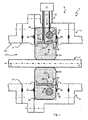
figure 1 is a cross-section detail of a first embodiment of a transmission line according to the invention, in a plane comprising a longitudinal axis of the transmission line; -
figure 2 is a cross-section detail of the transmission line offigure 1 , in a plane orthogonal to the longitudinal axis; -
figure 3 is a cross-section detail of a second embodiment of the transmission line according to the invention, in the same plane as infigure 1 ; -
figure 4 is a cross-section detail of a third embodiment of the transmission line according to the invention, in the same plane as infigure 1 ; -
figure 5 is a cross-section detail of a fourth embodiment of the transmission line according to the invention, in the same plane as infigure 1 ; -
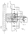
figure 6 is a cross-section detail of a fifth embodiment of the transmission line according to the invention, in the same plane as infigure 1 ; -
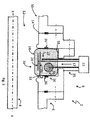
figure 7 is a cross-section detail of a sixth embodiment of the transmission line according to the invention, in a plane orthogonal to the longitudinal axis; and -
figure 8 is a cross-section detail of the embodiment offigure 7 , along a sectional plane AA. - A part of a
transmission line 2 according to the invention is shown onfigures 1 and2 . The transmission line is designed according to the standards of SF6 technology (SF6 standing for "sulfur hexafluoride"). For instance, thetransmission line 2 is a part of a gas insulated switchgear. - The
transmission line 2 comprises aconductor 4, agrounding pipe 6 enclosing theconductor 4, and asensing device 8. - The
conductor 4 is able to convey electric current from a first end of thetransmission line 2 to a second end of thetransmission line 2. - As can be seen on
figure 1 , thegrounding pipe 6 has a rotational symmetry around a longitudinal axis X-X. Thegrounding pipe 6 is configured to be electrically connected to a reference electric potential source, for instance to be connected to the ground. Thegrounding pipe 6 is also configured to allow the circulation of a reverse current flowing in an opposite direction relative to the current flowing in theconductor 4. - The
sensing device 8 is configured to measure the value of the conductor-to-pipe voltage, equal to the difference in electric potential between theconductor 4 and thegrounding pipe 6. Thesensing device 8 is also configured to compute the value of the electric current flowing through theconductor 4. - Each of the
conductor 4 and thegrounding pipe 6 is made of an electrically conductive material, such as a metal. - The grounding
pipe 6 is a hollow cylinder extending along the longitudinal axis X-X. The groundingpipe 6 comprises awall 10 defining acavity 12 inside the groundingpipe 6. - The
wall 10 includes an inner-facingsurface 14 facing toward thecavity 12. Thewall 10 also comprises agroove 16 on the inner-facingsurface 14 side. - The
groove 16 is ring shaped and is defined in a plane orthogonal to the longitudinal axis X-X. Thegroove 16 comprises ahole 17 to connect thecavity 12 to the outside of thegrounding pipe 6. - The
cavity 12 is filled with an insulating gas. For instance, such an insulating gas is sulfur hexafluoride (also known as SF6). - The
conductor 4 is a solid cylinder arranged in thecavity 12 of thegrounding pipe 6, theconductor 4 being spaced apart from the groundingpipe 6. - The
conductor 4 also extends along the longitudinal axis X-X. - The
sensing device 8 comprises avoltage sensor 18, acurrent sensor 20 and acomputer 22. Advantageously, thesensing device 8 also comprises a least onetemperature sensor 23. Thesensing device 8 further comprises acasing 24 molded around thevoltage sensor 18, thecurrent sensor 20 and, preferably, eachtemperature sensor 23. - The
voltage sensor 18 comprises areference plate 26 and asensing plate 28. Thereference plate 26 and thesensing plate 28 are made of an electrically conductive material. Thereference plate 26 and thesensing plate 28 are ring-shaped. For instance, each of thereference plate 26 and thesensing plate 28 is a metallic strip having both ends joined together. For instance, thereference plate 26 and thesensing plate 28 are metallic planes located on opposite sides of a flexible circuit board. - As shown on
figure 2 , thereference plate 26 and thesensing plate 28 are concentric and arranged at a distance from each other. Thesensing plate 28 is arranged inwardly with respect to thereference plate 26. More precisely, thereference plate 26 comprises an inward-facingsurface 30 that is directed inwardly towards the longitudinal axis X-X, and thesensing plate 28 comprises an outward-facingsurface 32 that is directed outwardly away from the longitudinal axis X-X, the inward-facingsurface 30 of thereference plate 26 facing the outward-facingsurface 32 of thesensing plate 28. - The
reference plate 26 and thesensing plate 28 are arranged within thegrounding pipe 6 and around theconductor 4, thereference plate 26 and thesensing plate 28 extending in a plane that is preferably orthogonal to the longitudinal axis X-X. - The
reference plate 26 is electrically connected to thegrounding pipe 6 to make the electric potential of thereference plate 26 equal to the electric potential of thegrounding pipe 6. Advantageously, thereference plate 26 is connected to thegrounding pipe 6 through at least one elastic contactingblade 33, the contactedblades 33 being located on a same edge of thereference plate 26. The contactingblades 33 are made of an electrically conductive material such as a copper and beryllium alloy, which has suitable elastic and electric properties for maintaining a mechanical and electrical contact between the contactingblades 33 and thegrounding pipe 6. - The
voltage sensor 18 is located at the same position along the longitudinal axis X-X as thegroove 16. Preferably, thereference plate 26 is arranged in thegroove 16, as shown onfigure 1 . - The
voltage sensor 18 is adapted to output a voltage signal representative of a voltage value between thereference plate 26 and thesensing plate 28. - The
current sensor 20 comprises a ring shapedRogowski coil 34 located within thegrounding pipe 6 and around theconductor 4. TheRogowski coil 34 defines a plane that is preferably orthogonal to the longitudinal axis X-X. - The
Rogowski coil 34 is arranged in thegroove 16. Moreover, theRogowski coil 34 is concentric with thereference plate 26 and thesensing plate 28, theRogowski coil 34 being arranged outwardly with respect to thereference plate 26, as shown onfigure 2 . Thereference plate 26 shields theRogowski coil 34 from thesensing plate 28, that is to say that thereference plate 26 is able to stop the electric field lines coming from thesensing plate 28 or coming to thesensing plate 28, thereference plate 26 being at the same voltage potential as thegrounding pipe 6. - For instance, the Rogowski coil has a circular cross-section.
- The
current sensor 20 is able to output a current signal representative of a current flowing through theconductor 4 that is encircled by theRogowski coil 34. - With reference to
figure 1 , eachtemperature sensor 23 is located at a predetermined position relative to thevoltage sensor 18. Furthermore, eachtemperature sensor 23 is configured to output a temperature signal representative of the temperature in a corresponding predetermined volume around the predetermined position relative to thevoltage sensor 18. - Each
sensor wires 35 that connect thesensors computer 22. Thewires 35 are conveyed through thehole 17. - As stated previously, the
casing 24 is molded around thevoltage sensor 18, thecurrent sensor 20 and, preferably, eachtemperature sensor 23. More precisely, thecasing 24 is molded around thereference plate 26, thesensing plate 28, theRogowski coil 34 and, preferably, eachtemperature sensor 23. - The
casing 24 is made of a dielectric material. Such a dielectric material is, for example, an epoxy resin, an epoxy and aluminium oxide mixture, or plastic. Such a plastic is, for instance, polyurethane, polyester or high-density polyethylene. - The
casing 24 extends within theg roove 16. Preferably,gas gaskets 36 are provided between thecasing 24 and thewall 10 of thegrounding pipe 6, for instance between thecasing 24 and the part of the inner facingsurface 14 located in thegroove 16, to avoid gas leakage outside thetransmission line 2 through thehole 17. - Advantageously, the
casing 23 is in mechanical contact with thegrounding pipe 6 and theconductor 4 to support the conductor. - The
computer 22 is configured to compute the value of the conductor-to-pipe voltage from the voltage signal outputted by thevoltage sensor 18. Advantageously, thecomputer 22 is further configured to correct the measured conductor-to-pipe voltage by using the temperature signal outputted by eachtemperature sensor 23 in order to compensate for the effects of temperature fluctuations on the geometry of thevoltage sensor 18. - Moreover, the
computer 22 is configured to compute the value of the electric current flowing through theconductor 4 from the current signal outputted by thecurrent sensor 20. - In a second embodiment of the
transmission line 2, shown onfigure 3 , thecasing 24 does not support the conductor 4 (the lower part of the cross-section is not shown for clarity purposes). - In a third embodiment of the
transmission line 2, no contactingblades 33 are provided. In this case, thereference plate 26 is connected to the grounding pipe through at least onewire 35A, as shown onfigure 4 (the lower part of the cross-section is not shown for clarity purposes). - In a fourth embodiment of the
transmission line 2, theRogowski coil 34 has a rectangular cross-section, as shown onfigure 5 (thetemperature sensor 23 and the lower part of the cross-section are not shown for clarity purposes). In such an embodiment, the rectangular cross-sectional area is greater than the circular cross-sectional area of the previous embodiment, which provides for a higher sensitivity. - In a fifth embodiment of the
transmission line 2, thesensing device 8 comprises asplitter 38, as shown onfigure 6 (thetemperature sensor 23 and the lower part of the cross-section are not shown for clarity purposes). - The
splitter 38 comprises an input that is connected to thesensing plate 28. Thesplitter 38 further comprises a first output forming a low frequency (LF)channel 40 and a second output forming an ultra-high frequency (UHF)channel 42, bothchannels computer 22. Thesplitter 38 is configured to convey, through theLF channel 40, a part of the voltage signal having a frequency that is lower than a first predetermined value, forinstance 10 kHz (kilohertz). Moreover, thesplitter 38 is configured to convey, through theUHF channel 42, a part of the voltage signal having a frequency that is higher than a second predetermined value, for instance 300 to 1200 MHz (megahertz). In this case, thecomputer 22 is configured to compute the value of the conductor-to-pipe voltage from the part of the voltage signal conveyed through theLF channel 40. Thecomputer 22 is further configured to detect partial discharges occurring in thetransmission line 2 through the analysis of the part of the voltage signal conveyed through theUHF channel 42. - In a sixth embodiment of the
transmission line 2, threeconductors 4 are provided within thegrounding pipe 6, as shown onfigure 7 . Theconductors 4 are spaced apart from one another. Each conductor corresponds to a respective electric phase. - Moreover, a
sensing device 8 as described above is provided for eachconductor 4, as shown onfigure 8 . - The
sensing plate 28 and theRogowski coil 34 of eachsensing device 8 are arranged exclusively around the correspondingconductor 4, between the groundingpipe 6 and the correspondingconductor 4. - Preferably, a
flange 44 is provided to support eachconductor 4. - The
flange 44 is made of an electrically conductive material. - For instance, as shown on
figure 7 , theflange 44 is disc-shaped. Theflange 44 comprises arim 46 for mechanically and electrically connecting theflange 44 to thegrounding tube 6, as shown onfigure 8 . - For each
conductor 4, theflange 44 comprises adepression 48 configured to receive thecasing 24 of thecorresponding sensing device 8, and thevoltage sensor 18, thecurrent sensor 20 and thetemperature sensors 23 embedded in thecasing 24. For instance, thedepression 48 has a shape that is complementary to the shape of thecasing 24 arranged in thedepression 48. - Furthermore, the
reference plate 26 of eachsensing device 8 is electrically connected to theflange 4. - Preferably, a
single computer 22 is provided to process the signal coming from eachsensing device 8. - The sensing device according to the invention is more compact, lighter, cheaper and easier to produce, and easier to assemble than the known sensing devices.
- The sensing device according to the invention also provides more reliable and precise voltage and current measurements.
- Moreover, such a sensing device requires fewer gas gaskets, and reduces the risk of gas leakage, which entails higher safety.
- In the
transmission line 2 according to the invention, since thereference plate 26 acts as a ground plane that shields theRogowski coil 34, no additional shield is required. Therefore, thecasing 24 is in direct contact with theRogowski coil 34, which stabilizes the geometry of theRogowski coil 34. This allows for a higher precision regarding the current measurement.
Claims (15)
- A sensing device (8) comprising:- a voltage sensor (18), the voltage sensor (18) comprising a reference plate (26) and a sensing plate (28), the reference plate (26) and the sensing plate (28) being ring-shaped, concentric and arranged at a distance from each other, an inward-facing surface of the reference plate (26) facing an outward-facing surface of the sensing plate (28), each of the reference plate (26) and the sensing plate (28) being made of an electrically conductive material, the voltage sensor (18) being adapted to output a voltage signal representative of a voltage value between the reference plate (26) and the sensing plate (28);- a current sensor, the current sensor comprising a ring shaped Rogowski coil (34), the current sensor being adapted to output a current signal representative of a current flowing through a conductor (4) encircled by the Rogowski coil (34);the sensing device (8) being characterized in that the Rogowski coil (34) is concentric with the reference plate (26) and the sensing plate (28), the reference plate (26) being arranged between the Rogowski coil (34) and the sensing plate (28), the reference plate (26) shielding the Rogowski coil (34) from the sensing plate (28), the Rogowski coil (34) being arranged outwardly with respect to the reference plate (26), and the sensing plate (28) being arranged inwardly with respect to the reference plate (26).
- The sensing device (8) according to claim 1, further comprising at least one temperature sensor each configured to output a temperature signal representative of the temperature in a corresponding predetermined volume relative to the voltage sensor (18).
- The sensing device (8) according to claim 1 or 2, further comprising a casing (24) molded around the reference plate (26), the sensing plate (28) and the Rogowski coil (34), the casing (24) being made of a dielectric material.
- The sensing device (8) according to claim 2, further comprising a casing (24) molded around the reference plate (26), the sensing plate (28), the Rogowski coil (34) and each temperature sensor, the casing (24) being made of a dielectric material.
- The sensing device (8) according to any one of claims 1 to 4, further comprising a splitter (38), the splitter (38) having an input connected to the sensing plate (28), the splitter (38) further comprising a first output forming a low frequency channel (40) and a second output forming an ultra-high frequency channel (42).
- A transmission line (2) comprising a grounding pipe (6) and at least one conductor (4) arranged within the grounding pipe (6), the grounding pipe (6) and each conductor (4) being made of an electrically conductive material, the grounding pipe (6) and each conductor (4) extending along a same longitudinal axis (X-X), each conductor (4) being spaced apart from the grounding pipe (6),
the transmission line (2) further comprising, for each conductor (4), a sensing device (8) according to any one of claims 1 to 5, the reference plate (26), the sensing plate (28) and the Rogowski coil (34) of each sensing device (8) being arranged exclusively around the corresponding conductor (4) between the grounding pipe (6) and the corresponding conductor (4),
the reference plate (26) of each sensing device (8) being electrically connected to the grounding pipe (6). - The transmission line (2) according to claim 6, further comprising a computer (22) configured to compute the value of the conductor-to-pipe voltage from the voltage signal outputted by the voltage sensor (18) of each sensing device (8), the computer being further configured to compute the value of the electric current flowing through each conductor (4) from the current signal outputted by the current sensor (20) of the corresponding sensing device (8).
- The transmission line (2) according to claim 7, further comprising, for each sensing device (8), a splitter (38), the splitter (38) having an input connected to the sensing plate (28), the splitter (38) further comprising a first output forming a low frequency channel (40) and a second output forming an ultra-high frequency channel (42), the low frequency channel (40) and the ultra-high frequency channel (42) being both connected to the computer (22), the splitter (38) being configured to convey, through the low frequency channel (40), a part of the voltage signal having a frequency that is lower than a first predetermined value, and to convey, through the ultra-high frequency channel (42), a part of the voltage signal having a frequency that is higher than a second predetermined value, the computer (22) being configured to compute, for each sensing device (8), the value of the conductor-to-pipe voltage from the part of the voltage signal conveyed through the low frequency channel (40), the computer (22) being further configured to detect partial discharges occurring in the transmission line (2) through the analysis of the part of the voltage signal conveyed through the ultra-high frequency channel (42).
- The transmission line (2) according to claim 7 or 8, wherein, for each sensing device (8), the computer (22) is further configured to correct the measured conductor-to-pipe voltage by using the temperature signal outputted by each temperature sensor (23) in order to compensate for the effects of temperature fluctuations on the geometry of the voltage sensor (18).
- The transmission line (2) according to any one of claims 6 to 9, wherein, for each sensing device (8), the reference plate (26) is electrically connected to the grounding pipe (6) through at least one elastic contacting blade (33).
- The transmission line (2) according to claim 10, wherein the contacting blades (33) are located on a same edge of the reference plate (26).
- The transmission line (2) according to any one of claims 6 to 9, wherein, for each sensing device (8), the reference plate (26) is electrically connected to the grounding pipe (6) through a wire (35A).
- The transmission line (2) according to any one of claims 6 to 12, wherein the transmission line (2) comprises a single conductor (4), the grounding pipe (6) being provided with a ring-shaped groove (16) on an inward-facing surface of the grounding pipe (6), the Rogowski coil (34) being arranged in the groove (16).
- The transmission line (2) according to claim 13, wherein the reference plate (26) is arranged in the groove (16).
- The transmission line (2) according to any of claims 6 to 14, wherein each sensing device (8) further comprises a casing (24) molded around the reference plate (26), the sensing plate (28) and the Rogowski coil (34), the casing (24) being made of a dielectric material, the casing (24) being in mechanical contact with the grounding pipe (6) and the conductor (4) to support the conductor (4).
Priority Applications (2)
| Application Number | Priority Date | Filing Date | Title |
|---|---|---|---|
| EP16182083.2A EP3276363A1 (en) | 2016-07-29 | 2016-07-29 | Sensing device and associated transmission line |
| PCT/EP2017/069251 WO2018020043A1 (en) | 2016-07-29 | 2017-07-28 | Sensing device and associated transmission line |
Applications Claiming Priority (1)
| Application Number | Priority Date | Filing Date | Title |
|---|---|---|---|
| EP16182083.2A EP3276363A1 (en) | 2016-07-29 | 2016-07-29 | Sensing device and associated transmission line |
Publications (1)
| Publication Number | Publication Date |
|---|---|
| EP3276363A1 true EP3276363A1 (en) | 2018-01-31 |
Family
ID=56567442
Family Applications (1)
| Application Number | Title | Priority Date | Filing Date |
|---|---|---|---|
| EP16182083.2A Withdrawn EP3276363A1 (en) | 2016-07-29 | 2016-07-29 | Sensing device and associated transmission line |
Country Status (2)
| Country | Link |
|---|---|
| EP (1) | EP3276363A1 (en) |
| WO (1) | WO2018020043A1 (en) |
Cited By (8)
| Publication number | Priority date | Publication date | Assignee | Title |
|---|---|---|---|---|
| WO2020035533A1 (en) * | 2018-08-16 | 2020-02-20 | Greenwood-Power OG | Apparatus for measuring current intensity and voltage |
| WO2021023471A1 (en) * | 2019-08-08 | 2021-02-11 | Siemens Energy Global GmbH & Co. KG | Measuring an electrical voltage on a metal-encapsulated switchgear |
| EP3783370A1 (en) * | 2019-08-20 | 2021-02-24 | LEM International SA | Rogowski current transducer |
| WO2021136710A1 (en) * | 2019-12-31 | 2021-07-08 | Eaton Intelligent Power Limited | Sensor part for installation in medium-voltage cable compartments and a device for measuring a voltage in medium-voltage circuits comprising such sensor part |
| WO2024006615A1 (en) * | 2022-06-29 | 2024-01-04 | Siemens Energy Global GmbH & Co. KG | Low power instrument transformer (lpit) in conical connector |
| EP4390407A1 (en) * | 2022-12-19 | 2024-06-26 | General Electric Technology GmbH | Device for measuring temperature gradients applied to a precision rogowski sensor |
| EP4425192A1 (en) * | 2023-03-02 | 2024-09-04 | General Electric Technology GmbH | Device for measuring temperature gradients applied to a precision capacitive divider voltage sensor |
| EP4667946A1 (en) | 2024-06-17 | 2025-12-24 | GE Vernova Technology GmbH | Sensing device comprising a capacitive voltage sensor and a rogowski coil current sensor and corresponding transmission line |
Families Citing this family (1)
| Publication number | Priority date | Publication date | Assignee | Title |
|---|---|---|---|---|
| DE102024209795A1 (en) * | 2024-10-08 | 2026-04-09 | Siemens Energy Global GmbH & Co. KG | Measuring transducer arrangement with a voltage sensor |
Citations (5)
| Publication number | Priority date | Publication date | Assignee | Title |
|---|---|---|---|---|
| US5432438A (en) * | 1991-06-29 | 1995-07-11 | Asea Brown Boverti Ltd. | Combined current and voltage transformer for a metal-enclosed gas-insulated high-voltage switching station |
| EP2136216A1 (en) * | 2008-06-19 | 2009-12-23 | ABB Technology AG | A combined electrical measurement device |
| DE102012204179A1 (en) * | 2012-03-16 | 2013-09-19 | Siemens Aktiengesellschaft | Transducer arrangement |
| US20130271116A1 (en) * | 2010-12-15 | 2013-10-17 | Abb Technology Ag | Combined measuring and detection system |
| EP2722678A1 (en) * | 2012-10-18 | 2014-04-23 | ABB Technology AG | Current and/or voltage sensing device for integrative use |
-
2016
- 2016-07-29 EP EP16182083.2A patent/EP3276363A1/en not_active Withdrawn
-
2017
- 2017-07-28 WO PCT/EP2017/069251 patent/WO2018020043A1/en not_active Ceased
Patent Citations (5)
| Publication number | Priority date | Publication date | Assignee | Title |
|---|---|---|---|---|
| US5432438A (en) * | 1991-06-29 | 1995-07-11 | Asea Brown Boverti Ltd. | Combined current and voltage transformer for a metal-enclosed gas-insulated high-voltage switching station |
| EP2136216A1 (en) * | 2008-06-19 | 2009-12-23 | ABB Technology AG | A combined electrical measurement device |
| US20130271116A1 (en) * | 2010-12-15 | 2013-10-17 | Abb Technology Ag | Combined measuring and detection system |
| DE102012204179A1 (en) * | 2012-03-16 | 2013-09-19 | Siemens Aktiengesellschaft | Transducer arrangement |
| EP2722678A1 (en) * | 2012-10-18 | 2014-04-23 | ABB Technology AG | Current and/or voltage sensing device for integrative use |
Non-Patent Citations (1)
| Title |
|---|
| MEIJER S ET AL: "Partial discharge early warning system in gas-insulated switchgear", IEEE/PES TRANSMISSION AND DISTRIBUTION CONFERENCE AND EXHIBITION 2002 : ASIA PACIFIC. YOKOHAMA, JAPAN, OCT. 6 - 10, 2002; [IEEE/PES TRANSMISSION AND DISTRIBUTION CONFERENCE AND EXPOSITION], NEW YORK, NY : IEEE, US, vol. 2, 6 October 2002 (2002-10-06), pages 931 - 936, XP010630437, ISBN: 978-0-7803-7525-3, DOI: 10.1109/TDC.2002.1177601 * |
Cited By (13)
| Publication number | Priority date | Publication date | Assignee | Title |
|---|---|---|---|---|
| WO2020035533A1 (en) * | 2018-08-16 | 2020-02-20 | Greenwood-Power OG | Apparatus for measuring current intensity and voltage |
| WO2021023471A1 (en) * | 2019-08-08 | 2021-02-11 | Siemens Energy Global GmbH & Co. KG | Measuring an electrical voltage on a metal-encapsulated switchgear |
| US11982691B2 (en) | 2019-08-08 | 2024-05-14 | Siemens Energy Global GmbH & Co. KG | Measuring an electrical voltage on a metal-encapsulated switchgear |
| EP3783370A1 (en) * | 2019-08-20 | 2021-02-24 | LEM International SA | Rogowski current transducer |
| WO2021032661A1 (en) * | 2019-08-20 | 2021-02-25 | Lem International Sa | Rogowski current transducer |
| US12007415B2 (en) | 2019-08-20 | 2024-06-11 | Lem International Sa | Rogowski current transducer |
| US12092663B2 (en) | 2019-12-31 | 2024-09-17 | Eaton Intelligent Power Limited | Sensor part for installation in medium-voltage cable compartments and a device for measuring a voltage in medium-voltage circuits comprising such sensor part |
| WO2021136710A1 (en) * | 2019-12-31 | 2021-07-08 | Eaton Intelligent Power Limited | Sensor part for installation in medium-voltage cable compartments and a device for measuring a voltage in medium-voltage circuits comprising such sensor part |
| GB2590987A (en) * | 2019-12-31 | 2021-07-14 | Eaton Intelligent Power Ltd | Sensor part for installation in medium-voltage cable compartments and a device for measuring a voltage in medium-voltage circuits comprising such sensor part |
| WO2024006615A1 (en) * | 2022-06-29 | 2024-01-04 | Siemens Energy Global GmbH & Co. KG | Low power instrument transformer (lpit) in conical connector |
| EP4390407A1 (en) * | 2022-12-19 | 2024-06-26 | General Electric Technology GmbH | Device for measuring temperature gradients applied to a precision rogowski sensor |
| EP4425192A1 (en) * | 2023-03-02 | 2024-09-04 | General Electric Technology GmbH | Device for measuring temperature gradients applied to a precision capacitive divider voltage sensor |
| EP4667946A1 (en) | 2024-06-17 | 2025-12-24 | GE Vernova Technology GmbH | Sensing device comprising a capacitive voltage sensor and a rogowski coil current sensor and corresponding transmission line |
Also Published As
| Publication number | Publication date |
|---|---|
| WO2018020043A1 (en) | 2018-02-01 |
Similar Documents
| Publication | Publication Date | Title |
|---|---|---|
| WO2018020043A1 (en) | Sensing device and associated transmission line | |
| EP2693223B1 (en) | Voltage measurement device with an insulating body | |
| US6850399B1 (en) | Gas insulated device and failure rating method | |
| CN104641243B (en) | Medium or high voltage installations with cable connection terminals | |
| CN102138261B (en) | Gas-insulated device | |
| EP2909641B1 (en) | Current and/or voltage sensing device for integrative use | |
| EP3236272B1 (en) | High-voltage lead-in insulating device | |
| US9863995B2 (en) | Antenna-and-cable connection-state verification device and verification method | |
| AU2013231500B2 (en) | Measuring transducer arrangement | |
| KR102906797B1 (en) | Voltage measuring device for high voltage power equipment | |
| US6853528B2 (en) | Gas insulating apparatus and method for locating fault point thereof | |
| CN111316113A (en) | Voltage Divider Components | |
| US8456787B2 (en) | Gas insulated switchgear | |
| KR20220111771A (en) | Current and voltage sensing sensor | |
| US7336083B2 (en) | Connecting sleeve for a bus bar connection in a gas-insulated switchboard system | |
| US11982691B2 (en) | Measuring an electrical voltage on a metal-encapsulated switchgear | |
| JP6627242B2 (en) | Partial discharge measurement device | |
| JPWO2015049725A1 (en) | Partial discharge sensor | |
| KR102752605B1 (en) | Insulated housing with rvd | |
| KR102872860B1 (en) | Electronic voltage sensor | |
| KR20210092791A (en) | Current transformer modules for switchgear and corresponding switchgear | |
| JP2007199008A (en) | Diagnostic equipment for gas-insulated electrical equipment | |
| HK40000523A (en) | High-voltage lead-in insulating device | |
| HK1087541B (en) | Connecting sleeve, bus bar connection with the same and switchboard system |
Legal Events
| Date | Code | Title | Description |
|---|---|---|---|
| PUAI | Public reference made under article 153(3) epc to a published international application that has entered the european phase |
Free format text: ORIGINAL CODE: 0009012 |
|
| AK | Designated contracting states |
Kind code of ref document: A1 Designated state(s): AL AT BE BG CH CY CZ DE DK EE ES FI FR GB GR HR HU IE IS IT LI LT LU LV MC MK MT NL NO PL PT RO RS SE SI SK SM TR |
|
| AX | Request for extension of the european patent |
Extension state: BA ME |
|
| STAA | Information on the status of an ep patent application or granted ep patent |
Free format text: STATUS: THE APPLICATION IS DEEMED TO BE WITHDRAWN |
|
| 18D | Application deemed to be withdrawn |
Effective date: 20180801 |