EP3276204A1 - Auto tensioner and auto tensioner-integrated engine auxiliary device - Google Patents
Auto tensioner and auto tensioner-integrated engine auxiliary device Download PDFInfo
- Publication number
- EP3276204A1 EP3276204A1 EP16206785.4A EP16206785A EP3276204A1 EP 3276204 A1 EP3276204 A1 EP 3276204A1 EP 16206785 A EP16206785 A EP 16206785A EP 3276204 A1 EP3276204 A1 EP 3276204A1
- Authority
- EP
- European Patent Office
- Prior art keywords
- auto tensioner
- water pump
- driving
- plate
- driven plate
- Prior art date
- Legal status (The legal status is an assumption and is not a legal conclusion. Google has not performed a legal analysis and makes no representation as to the accuracy of the status listed.)
- Granted
Links
- 230000005540 biological transmission Effects 0.000 claims abstract description 57
- XLYOFNOQVPJJNP-UHFFFAOYSA-N water Substances O XLYOFNOQVPJJNP-UHFFFAOYSA-N 0.000 description 97
- 230000008878 coupling Effects 0.000 description 10
- 238000010168 coupling process Methods 0.000 description 10
- 238000005859 coupling reaction Methods 0.000 description 10
- 239000002826 coolant Substances 0.000 description 5
- 239000000446 fuel Substances 0.000 description 4
- 238000002347 injection Methods 0.000 description 4
- 239000007924 injection Substances 0.000 description 4
- 238000001746 injection moulding Methods 0.000 description 4
- 238000001816 cooling Methods 0.000 description 2
- 238000005461 lubrication Methods 0.000 description 2
- 239000000463 material Substances 0.000 description 2
- 230000006866 deterioration Effects 0.000 description 1
- 239000010687 lubricating oil Substances 0.000 description 1
- 238000012986 modification Methods 0.000 description 1
- 230000004048 modification Effects 0.000 description 1
- 239000003208 petroleum Substances 0.000 description 1
- 238000005086 pumping Methods 0.000 description 1
Images





Classifications
-
- F—MECHANICAL ENGINEERING; LIGHTING; HEATING; WEAPONS; BLASTING
- F16—ENGINEERING ELEMENTS AND UNITS; GENERAL MEASURES FOR PRODUCING AND MAINTAINING EFFECTIVE FUNCTIONING OF MACHINES OR INSTALLATIONS; THERMAL INSULATION IN GENERAL
- F16H—GEARING
- F16H7/00—Gearings for conveying rotary motion by endless flexible members
- F16H7/08—Means for varying tension of belts, ropes or chains
- F16H7/10—Means for varying tension of belts, ropes or chains by adjusting the axis of a pulley
- F16H7/12—Means for varying tension of belts, ropes or chains by adjusting the axis of a pulley of an idle pulley
-
- F—MECHANICAL ENGINEERING; LIGHTING; HEATING; WEAPONS; BLASTING
- F16—ENGINEERING ELEMENTS AND UNITS; GENERAL MEASURES FOR PRODUCING AND MAINTAINING EFFECTIVE FUNCTIONING OF MACHINES OR INSTALLATIONS; THERMAL INSULATION IN GENERAL
- F16H—GEARING
- F16H7/00—Gearings for conveying rotary motion by endless flexible members
- F16H7/08—Means for varying tension of belts, ropes or chains
- F16H7/10—Means for varying tension of belts, ropes or chains by adjusting the axis of a pulley
- F16H7/14—Means for varying tension of belts, ropes or chains by adjusting the axis of a pulley of a driving or driven pulley
- F16H7/16—Means for varying tension of belts, ropes or chains by adjusting the axis of a pulley of a driving or driven pulley without adjusting the driving or driven shaft
-
- F—MECHANICAL ENGINEERING; LIGHTING; HEATING; WEAPONS; BLASTING
- F16—ENGINEERING ELEMENTS AND UNITS; GENERAL MEASURES FOR PRODUCING AND MAINTAINING EFFECTIVE FUNCTIONING OF MACHINES OR INSTALLATIONS; THERMAL INSULATION IN GENERAL
- F16H—GEARING
- F16H7/00—Gearings for conveying rotary motion by endless flexible members
- F16H7/08—Means for varying tension of belts, ropes or chains
-
- F—MECHANICAL ENGINEERING; LIGHTING; HEATING; WEAPONS; BLASTING
- F01—MACHINES OR ENGINES IN GENERAL; ENGINE PLANTS IN GENERAL; STEAM ENGINES
- F01P—COOLING OF MACHINES OR ENGINES IN GENERAL; COOLING OF INTERNAL-COMBUSTION ENGINES
- F01P5/00—Pumping cooling-air or liquid coolants
- F01P5/10—Pumping liquid coolant; Arrangements of coolant pumps
-
- F—MECHANICAL ENGINEERING; LIGHTING; HEATING; WEAPONS; BLASTING
- F01—MACHINES OR ENGINES IN GENERAL; ENGINE PLANTS IN GENERAL; STEAM ENGINES
- F01P—COOLING OF MACHINES OR ENGINES IN GENERAL; COOLING OF INTERNAL-COMBUSTION ENGINES
- F01P5/00—Pumping cooling-air or liquid coolants
- F01P5/10—Pumping liquid coolant; Arrangements of coolant pumps
- F01P5/12—Pump-driving arrangements
-
- F—MECHANICAL ENGINEERING; LIGHTING; HEATING; WEAPONS; BLASTING
- F02—COMBUSTION ENGINES; HOT-GAS OR COMBUSTION-PRODUCT ENGINE PLANTS
- F02B—INTERNAL-COMBUSTION PISTON ENGINES; COMBUSTION ENGINES IN GENERAL
- F02B67/00—Engines characterised by the arrangement of auxiliary apparatus not being otherwise provided for, e.g. the apparatus having different functions; Driving auxiliary apparatus from engines, not otherwise provided for
- F02B67/04—Engines characterised by the arrangement of auxiliary apparatus not being otherwise provided for, e.g. the apparatus having different functions; Driving auxiliary apparatus from engines, not otherwise provided for of mechanically-driven auxiliary apparatus
- F02B67/06—Engines characterised by the arrangement of auxiliary apparatus not being otherwise provided for, e.g. the apparatus having different functions; Driving auxiliary apparatus from engines, not otherwise provided for of mechanically-driven auxiliary apparatus driven by means of chains, belts, or like endless members
-
- F—MECHANICAL ENGINEERING; LIGHTING; HEATING; WEAPONS; BLASTING
- F16—ENGINEERING ELEMENTS AND UNITS; GENERAL MEASURES FOR PRODUCING AND MAINTAINING EFFECTIVE FUNCTIONING OF MACHINES OR INSTALLATIONS; THERMAL INSULATION IN GENERAL
- F16H—GEARING
- F16H39/00—Rotary fluid gearing using pumps and motors of the volumetric type, i.e. passing a predetermined volume of fluid per revolution
-
- F—MECHANICAL ENGINEERING; LIGHTING; HEATING; WEAPONS; BLASTING
- F16—ENGINEERING ELEMENTS AND UNITS; GENERAL MEASURES FOR PRODUCING AND MAINTAINING EFFECTIVE FUNCTIONING OF MACHINES OR INSTALLATIONS; THERMAL INSULATION IN GENERAL
- F16H—GEARING
- F16H55/00—Elements with teeth or friction surfaces for conveying motion; Worms, pulleys or sheaves for gearing mechanisms
- F16H55/32—Friction members
- F16H55/36—Pulleys
-
- F—MECHANICAL ENGINEERING; LIGHTING; HEATING; WEAPONS; BLASTING
- F16—ENGINEERING ELEMENTS AND UNITS; GENERAL MEASURES FOR PRODUCING AND MAINTAINING EFFECTIVE FUNCTIONING OF MACHINES OR INSTALLATIONS; THERMAL INSULATION IN GENERAL
- F16H—GEARING
- F16H7/00—Gearings for conveying rotary motion by endless flexible members
- F16H7/08—Means for varying tension of belts, ropes or chains
- F16H7/10—Means for varying tension of belts, ropes or chains by adjusting the axis of a pulley
- F16H7/14—Means for varying tension of belts, ropes or chains by adjusting the axis of a pulley of a driving or driven pulley
-
- F—MECHANICAL ENGINEERING; LIGHTING; HEATING; WEAPONS; BLASTING
- F16—ENGINEERING ELEMENTS AND UNITS; GENERAL MEASURES FOR PRODUCING AND MAINTAINING EFFECTIVE FUNCTIONING OF MACHINES OR INSTALLATIONS; THERMAL INSULATION IN GENERAL
- F16H—GEARING
- F16H7/00—Gearings for conveying rotary motion by endless flexible members
- F16H7/08—Means for varying tension of belts, ropes or chains
- F16H2007/0802—Actuators for final output members
- F16H2007/0806—Compression coil springs
-
- F—MECHANICAL ENGINEERING; LIGHTING; HEATING; WEAPONS; BLASTING
- F16—ENGINEERING ELEMENTS AND UNITS; GENERAL MEASURES FOR PRODUCING AND MAINTAINING EFFECTIVE FUNCTIONING OF MACHINES OR INSTALLATIONS; THERMAL INSULATION IN GENERAL
- F16H—GEARING
- F16H7/00—Gearings for conveying rotary motion by endless flexible members
- F16H7/08—Means for varying tension of belts, ropes or chains
- F16H2007/0802—Actuators for final output members
- F16H2007/0808—Extension coil springs
-
- F—MECHANICAL ENGINEERING; LIGHTING; HEATING; WEAPONS; BLASTING
- F16—ENGINEERING ELEMENTS AND UNITS; GENERAL MEASURES FOR PRODUCING AND MAINTAINING EFFECTIVE FUNCTIONING OF MACHINES OR INSTALLATIONS; THERMAL INSULATION IN GENERAL
- F16H—GEARING
- F16H7/00—Gearings for conveying rotary motion by endless flexible members
- F16H7/08—Means for varying tension of belts, ropes or chains
- F16H2007/0802—Actuators for final output members
- F16H2007/0812—Fluid pressure
-
- F—MECHANICAL ENGINEERING; LIGHTING; HEATING; WEAPONS; BLASTING
- F16—ENGINEERING ELEMENTS AND UNITS; GENERAL MEASURES FOR PRODUCING AND MAINTAINING EFFECTIVE FUNCTIONING OF MACHINES OR INSTALLATIONS; THERMAL INSULATION IN GENERAL
- F16H—GEARING
- F16H7/00—Gearings for conveying rotary motion by endless flexible members
- F16H7/08—Means for varying tension of belts, ropes or chains
- F16H2007/0842—Mounting or support of tensioner
-
- F—MECHANICAL ENGINEERING; LIGHTING; HEATING; WEAPONS; BLASTING
- F16—ENGINEERING ELEMENTS AND UNITS; GENERAL MEASURES FOR PRODUCING AND MAINTAINING EFFECTIVE FUNCTIONING OF MACHINES OR INSTALLATIONS; THERMAL INSULATION IN GENERAL
- F16H—GEARING
- F16H7/00—Gearings for conveying rotary motion by endless flexible members
- F16H7/08—Means for varying tension of belts, ropes or chains
- F16H2007/0863—Finally actuated members, e.g. constructional details thereof
-
- F—MECHANICAL ENGINEERING; LIGHTING; HEATING; WEAPONS; BLASTING
- F16—ENGINEERING ELEMENTS AND UNITS; GENERAL MEASURES FOR PRODUCING AND MAINTAINING EFFECTIVE FUNCTIONING OF MACHINES OR INSTALLATIONS; THERMAL INSULATION IN GENERAL
- F16H—GEARING
- F16H7/00—Gearings for conveying rotary motion by endless flexible members
- F16H7/08—Means for varying tension of belts, ropes or chains
- F16H2007/0863—Finally actuated members, e.g. constructional details thereof
- F16H2007/0865—Pulleys
-
- F—MECHANICAL ENGINEERING; LIGHTING; HEATING; WEAPONS; BLASTING
- F16—ENGINEERING ELEMENTS AND UNITS; GENERAL MEASURES FOR PRODUCING AND MAINTAINING EFFECTIVE FUNCTIONING OF MACHINES OR INSTALLATIONS; THERMAL INSULATION IN GENERAL
- F16H—GEARING
- F16H7/00—Gearings for conveying rotary motion by endless flexible members
- F16H7/08—Means for varying tension of belts, ropes or chains
- F16H2007/0889—Path of movement of the finally actuated member
- F16H2007/0893—Circular path
Definitions
- the present disclosure relates to an auto tensioner and an auto tensioner-integrated engine auxiliary device. More particularly, the present disclosure relates to an auto tensioner and an auto tensioner-integrated engine auxiliary device, which are capable of normally performing both a function of the engine auxiliary device and a function of adjusting tension of a power transmission belt.
- driving power generated by an engine of an automobile is used as a power source for driving engine auxiliary devices as well as for rotating vehicle wheels to allow the automobile to travel, and as the auxiliary devices that use driving power from the engine as a power source as described above, there are, for example, a generator, a water pump, and an air-conditioner compressor.
- the auxiliary devices are typically configured to operate by receiving the driving power from the engine by a belt (power transmission belt), and to this end, a driven pulley is provided which operates in conjunction with a crank shaft pulley of the engine by the belt.
- a belt power transmission belt
- the auxiliary devices which are connected to one another by the belt and receive the driving power from the engine, are equipped with an auto tensioner as a tension adjusting device for adjusting tension of the belt in order to prevent deterioration in power transmission efficiency, and the auto tensioner is typically mounted in a movement trajectory of the belt and imparts predetermined tension to a belt surface.
- the present disclosure has been made in an effort to solve the above-described problems associated with the prior art, and to provide an auto tensioner and an auto tensioner-integrated engine auxiliary device, which are capable of normally performing both a function of the engine auxiliary device and a function of adjusting tension of a power transmission belt.
- the present disclosure has been made in an effort to provide an auto tensioner-integrated engine auxiliary device in which a driving member is connected to a driven pulley of an engine auxiliary device (e.g., a water pump pulley) which is rotated by an operation of a belt such that belt tension may be adjusted by an eccentric movement of the driven pulley, and rotational power of the driven pulley may be normally and effectively transmitted to an output unit of the engine auxiliary device (e.g., a water pump impeller).
- an engine auxiliary device e.g., a water pump pulley
- an auto tensioner which is mounted on a rotating shaft of an engine auxiliary device rotating about the rotating shaft by a power transmitted through a power transmission belt, and pivots about a pivot shaft.
- the auto tensioner may have one side rotatably fastened to the pivot shaft and another side fastened to a driving member, and may pivot about the pivot shaft in accordance with an operation of the driving member.
- the driving member may include a cylinder portion that is operated by hydraulic pressure, and an elastic member, which provides a restoring force when the hydraulic pressure is eliminated, may be disposed on an outer circumferential surface of the cylinder portion.
- the auto tensioner may further include: a driving plate which is coupled to the rotating shaft and receives power; and a driven plate which rotates by receiving rotational force of the driving plate, in which a plurality of vanes, which transmit the rotational force of the driving plate to the driven plate, are disposed on the driven plate.
- Each of the vanes may include a head portion which is fixed to an edge portion of the driven plate, and a body portion which extends from the head portion toward a center of the driven plate, and the driving plate may have a driving block which has moving grooves in which the body portions are accommodated.
- a core portion may be inserted into the vane, and the body portion may be formed by injection molding so that a thickness thereof is increased in a direction toward a center of the driven plate.
- an auto tensioner-integrated engine auxiliary device including: a pulley unit which is rotated by power transmitted through a power transmission belt; a rotating shaft which is coupled to a center of the pulley unit and rotates simultaneously with the pulley unit; an output unit which rotates by receiving power of the rotating shaft; and an auto tensioner which operates such that the rotating shaft pivots about a pivot shaft.
- the auto tensioner may be mounted on the rotating shaft by a bearing (a first bearing) that is rotatable relative to the rotating shaft, and the auto tensioner may have one side rotatably fastened to the pivot shaft and another side fastened to a driving member, and may pivot about the pivot shaft in accordance with an operation of the driving member.
- a bearing a first bearing
- the driving member may include a cylinder portion that is operated by hydraulic pressure, and an elastic member, which provides restoring force when the hydraulic pressure is eliminated, may be disposed on an outer circumferential surface of the cylinder portion.
- the auto tensioner-integrated engine auxiliary device may further include: a driving plate which is coupled to the rotating shaft and receives power; and a driven plate which rotates by receiving rotational force of the driving plate, in which a plurality of vanes, which transmit the rotational force of the driving plate to the driven plate even when the rotating shaft pivots, are disposed on the driven plate.
- Each of the vanes may include a head portion which is fixed to an edge portion of the driven plate, and a body portion which extends from the head portion toward a center of the driven plate, and the driving plate may have a driving block which has moving grooves in which the body portions are accommodated.
- a core portion may be inserted into the vane, and the body portion may be formed by injection molding so that a thickness thereof is increased in a direction toward a center of the driven plate.
- the pulley unit may be a water pump pulley disposed in a water pump among the engine auxiliary devices, and the output unit may be a water pump impeller disposed in the water pump.
- an auto tensioner-integrated engine auxiliary device including: a water pump pulley which adjusts tension of a power transmission belt by pivoting about a pivot shaft and simultaneously rotates about a rotating shaft by power transmitted through the power transmission belt; and a power transmission unit which transmits rotational power of the water pump pulley, which rotates about the rotating shaft, to a water pump impeller.
- the water pump pulley may be coupled to an inner circumferential surface of a support bracket so as to be rotatable simultaneously with the rotating shaft, and the support bracket may have a driving member coupling hinge portion coupled to a driving member, and an engine coupling hinge portion mounted on an engine so as to be rotatable about a pivot shaft.
- the power transmission unit may include: a driving plate which is coupled to the water pump pulley so as to be rotatable and pivotable integrally with the water pump pulley; a driven plate which is coupled to the water pump impeller so as to be rotatable simultaneously with the water pump impeller and rotates by receiving rotational force of the driving plate; and a plurality of vanes which are assembled between the driving plate and the driven plate and transmit the rotational force of the driving plate to the driven plate even when the water pump pulley pivots.
- the vane may include a head portion which is fixed to the driven plate, and a body portion which is assembled to be linearly movable in a moving groove disposed in the driving plate, and the vane may have a neck portion which is connected between the head portion and the body portion and may have a narrowed shape, such that when the driving plate pivots about the pivot shaft, the body portion is resiliently bendable relative to the head portion.
- a driving block which has a plurality of moving grooves, may be disposed on the driving plate, and the moving grooves may extend in a radial direction from an outer circumferential surface of the driving block.
- the water pump pulley performs a function of a tensioner pulley which was used to adjust tension of the existing power transmission belt, it is possible to omit the existing tensioner pulley, reduce a size of a package, increase a mounting space, reduce a length of the power transmission belt, reduce costs and a weight, and improve fuel economy.
- vehicle or “vehicular” or other similar term as used herein is inclusive of motor vehicles in general such as passenger automobiles including sports utility vehicles (SUV), buses, trucks, various commercial vehicles, watercraft including a variety of boats and ships, aircraft, and the like, and includes hybrid vehicles, electric vehicles, plug-in hybrid electric vehicles, hydrogen-powered vehicles and other alternative fuel vehicles (e.g. fuel derived from resources other than petroleum).
- a hybrid vehicle is a vehicle that has two or more sources of power, for example both gasoline-powered and electric-powered vehicles.
- driven pulleys of various types of engine auxiliary devices are connected to a crank shaft pulley 12 of an engine 10 by a power transmission belt 16 so that the engine auxiliary devices may operate by receiving power from the engine.
- the engine auxiliary devices such as the generator, the water pump, and the air-conditioner compressor are configured to be rotationally operated by engine power supplied through the power transmission belt 16.
- the engine auxiliary device integrated with an auto tensioner 14, which may adjust tension of the power transmission belt 16 by using a water pump pulley 22 among driven pulleys (i.e., pulley units) of the engine auxiliary devices which are operated by receiving engine power through the power transmission belt 16, will be described.
- FIG. 1 illustrates a layout and an installed state of the auto tensioner-integrated engine auxiliary devices according to the exemplary embodiment of the present disclosure
- FIGS. 2 and 3 illustrate a configuration of the auto tensioner-integrated engine auxiliary device according to the exemplary embodiment of the present disclosure
- FIG. 4 illustrates an assembled structure of the auto tensioner-integrated engine auxiliary device according to the exemplary embodiment of the present disclosure
- FIG. 5 illustrates an enlarged view of a power transmission unit according to the exemplary embodiment of the present disclosure.
- the auto tensioner-integrated engine auxiliary device includes a water pump pulley part 20, a driving member 30, a power transmission unit 40, and a water pump impeller 50.
- the water pump pulley part 20 is pivotable about a pivot shaft 27 by power supplied by the hydraulic driving member 30.
- the driving member 30 includes a cylinder portion 31 which is extended by supplied hydraulic pressure, and an elastic member 32, which creates restoring force by being deformed, is provided on an outer circumferential surface of the cylinder portion 31.
- the driving member 30 provides power for pivoting the water pump pulley part 20 while being extended in an axial direction (or a longitudinal direction) by the supplied hydraulic pressure and creates elastic restoring force in accordance with deformation of the elastic member 32.
- the driving member 30 has a structure configured to return the water pump pulley part 20 by being restored by the elastic restoring force of the elastic member 32 when the hydraulic pressure is eliminated.
- One end portion of both end portions in the longitudinal direction of the driving member 30 is rotatably mounted on the engine (specifically, a cylinder block of the engine), and another end portion thereof is rotatably coupled to a support bracket 26 of the water pump pulley part 20.
- the support bracket 26 is mounted between the driving member 30 and the engine 10 and pivotable about the pivot shaft 27.
- An engine coupling hinge portion 26a which protrudes from one side of an outer circumferential surface of the support bracket 26, is rotatably mounted on the engine 10 by the pivot shaft 27, and a driving member coupling hinge portion 26b, which protrudes from another side of the outer circumferential surface of the support bracket 26, is rotatably fastened to one end portion of the driving member 30.
- the water pump pulley part 20 which includes the support bracket 26 and the water pump pulley 22, is pivoted about the pivot shaft 27 along an arc by pivoting power provided from the driving member 30 when the driving member 30 extends.
- the water pump pulley part 20 is provided with a rotating shaft 23 and an adapter 24 of the water pump pulley 22.
- the water pump pulley 22 imparts a predetermined tension to the power transmission belt 16 while rotating by receiving engine power through the power transmission belt 16 and while a center of rotation is eccentrically moved by pivoting power provided by the driving member 30.
- the water pump pulley 22 is mounted in a movement trajectory of the power transmission belt 16 so as to be movable by the driving member 30, and the water pump pulley 22 has an outer circumferential surface having a predetermined width so as to be in friction contact with the power transmission belt 16.
- the water pump pulley 22 has the rotating shaft 23 which is provided at the center of rotation of the water pump pulley 22 and rotates and pivots simultaneously with the water pump pulley 22, and the rotating shaft 23 is integrally coupled to the center of rotation of the water pump pulley 22 through the adapter 24.
- the rotating shaft 23 is rotatably coupled to an inner circumferential surface of the support bracket 26 by a first bearing 28, and as a result, the water pump pulley 22 may pivot, simultaneously with the support bracket 26, about the pivot shaft 27 in a state in which the water pump pulley 22 is stacked on the support bracket 26.
- the rotating shaft 23 penetrates the support bracket 26 and is integrally coupled to a rotation center (i.e., a shaft coupling portion) of a driving plate 42 in a press-fit manner, and may rotate and pivot simultaneously with the driving plate 42.
- a rotation center i.e., a shaft coupling portion
- a shaft coupling portion 42a of the driving plate 42 and the adapter 24 of the water pump pulley 22 are fixedly coupled to an inner race of the first bearing 28, and as a result, the rotating shaft 23 is rotatably coupled to the inner circumferential surface of the support bracket 26 by the first bearing 28.
- the adapter 24 and the shaft coupling portion 42a of the driving plate 42 which are coupled to the outer circumferential surface of the rotating shaft 23, are rotatably installed on the inner circumferential surface of the support bracket 26 by the first bearing 28, and as a result, the water pump pulley 22 and the driving plate 42 are supported to be rotatable simultaneously about the rotating shaft 23.
- the first bearing 28 is mounted on the inner circumferential surface of the support bracket 26 and rotatably supports the water pump pulley 22, the rotating shaft 23, and the driving plate 42.
- the power transmission unit 40 including the driving plate 42 includes a driven plate 44 and a plurality of vanes 46 as well as the driving plate 42.
- the power transmission unit 40 allows power to be normally transmitted to the water pump impeller 50 even though the rotation center of the water pump pulley 22 is eccentric from a center of rotation the water pump impeller 50 because of the pivot of the water pump pulley part 20.
- the driven plate 44 is coupled to a rotating shaft of the water pump impeller 50, that is, an impeller shaft 52 so as to be rotatable simultaneously with the impeller shaft 52
- the driving plate 42 is coupled to the rotating shaft 23 of the water pump pulley 22 so as to be rotatable simultaneously with the rotating shaft 23, and the plurality of vanes 46 for transmitting power is assembled between the driven plate 44 and the driving plate 42.
- Head portions 46a of the vanes 46 are fixedly mounted on an inner circumferential surface of a raised portion 44b which is formed as an edge portion of one surface of the driven plate 44 is raised, and a shaft coupling portion 44a, which is coupled to the impeller shaft 52, is formed at a center of rotation of another surface of the driven plate 44.
- the vanes 46 are of a pendulum type including the head portions 46a which are fixedly coupled to the driven plate 44, and body portions 46b which are assembled to be linearly movable in moving grooves 42c provided in the driving plate 42.
- the vanes 46 serve to effectively transmit rotational power of the driving plate 42 to the driven plate 44.
- the vanes 46 are assembled between the driving plate 42 and the driven plate 44 and normally transmit rotational force of the driving plate 42 to the driven plate 44 even when the water pump pulley 22 pivots.
- the vanes 46 allow rotational force of the driving plate 42 to be effectively transmitted to the driven plate 44 (see FIGS. 6A and 6B ).
- a driving block 42b which has the plurality of moving grooves 42c in which the body portions 46b of the vanes 46 may slide and linearly move, protrudes from one surface of the driving plate 42, and the body portions 46b of the vanes 46 are linearly movably inserted into the plurality of moving grooves 42c, respectively.
- the plurality of moving grooves 42c is disposed at predetermined intervals along an outer circumferential surface of the driving block 42b, and each of the moving grooves 42c extends in a radial direction from the outer circumferential surface to a center of rotation of the driving block 42b.
- the driving plate 42 Since the rotating shaft of the water pump pulley 22 is rotatably coupled to the center of rotation of the driving plate 42 in a press-fit manner, the driving plate 42 is moved simultaneously with the water pump pulley 22 when the water pump pulley 22 eccentrically moves. However, even when the driving plate 42 pivots, the driving plate 42 and the driven plate 44 are maintained to be connected by the vanes 46 so as to transmit power, and as a result, the rotational power of the driving plate 42 is normally transmitted to the driven plate 44 regardless of the eccentric movement of the driving plate 42, such that power is transmitted to the water pump impeller 50.
- each of the vanes 46 may have a neck portion 46c which is connected between the head portion 46a and the body portion 46b and has a narrowed shape. Therefore, when the driving plate 42 pivots about the pivot shaft 27, the body portion 46b is resiliently bent relative to the head portion 46a, such that the connection (the connection for power transmission) between the driving plate 42 and the driven plate 44 is maintained (see FIGS. 6A and 6B ).
- each of the vane has a structure in which a plate-shaped core portion 46d, which ensures rigidity and elasticity for power transmission, is inserted into the vane 46 in order to allow the rotational force of the driving plate 42 to be effectively transmitted to the driven plate 44 and to smoothly perform the linear movement in the moving grooves 42c, and an injection molded portion 46e, which is made of a plastic material and has a lubrication function and elasticity, is formed outside the core portion 46d by injection molding.
- the vane 46 includes the inner core portion 46d for ensuring rigidity and elasticity, and the outer injection molded portion 46e for ensuring linear mobility, and the injection molded portion 46e is divided into the head portion 46a, the body portion 46b, and the neck portion 46c.
- the body portion 46b extends from the head portion 46a toward the center of the driven plate 44 with the neck portion 46c interposed between the head portion 46a and the body portion 46b, and in this case, the body portion 46b is formed by injection molding such that a thickness of the body portion 46b is increased toward the center of the driven plate 44 (in a direction toward the center).
- the injection molded portion 46e serves to provide a lubrication function by using a material characteristic, without using lubricating oil, so that the body portion 46b of the vane 46 smoothly moves in the moving groove 42c of the driving plate 42.
- the impeller shaft 52 which is fixedly coupled to the center of rotation of the driven plate 44, is rotatably supported by a second bearing 56 mounted on an inner circumferential surface of a water pump bracket 54, and the water pump bracket 54 is fixedly mounted on the engine 10 (specifically, the cylinder block of the engine).
- the auto tensioner-integrated engine auxiliary device which is configured as described above, may perform a typical function of the water pump (a function of pumping a coolant) so as to circulate the coolant to be supplied to the engine, and may simultaneously adjust tension of the power transmission belt as necessary.
- the rotational force, which is transmitted to the water pump pulley 22 by the operation of the power transmission belt 16, is transmitted to the driving plate 42 through the rotating shaft 23 of the water pump pulley 22, and the rotational force of the driving plate 42 is transmitted to the driven plate 44 through the vanes 46, such that the rotational force caused by the operation of the power transmission belt 16 is transmitted to the water pump impeller 50 integrally coupled to the driven plate 44.
- the vanes 46 are resiliently deformed by being moved in the moving grooves 42c so that the driving plate 42 is pivotable, and the vanes 46 simultaneously maintains the connection state for power transmission between the driving plate 42 and the driven plate 44, as illustrated in FIGS. 6A and 6B , and as a result, the rotational force of the driving plate 42 is effectively transmitted to the driven plate 44, and the water pump impeller 50 normally rotates, such that the engine coolant is normally circulated by the rotation of the water pump impeller 50.
- the power transmission unit 40 may transmit the rotational force of the driving plate 42 to the driven plate 44 through the vanes 46 assembled between the driving plate 42 and the driven plate 44 regardless of the pivot of the driving plate 42 that moves integrally with the water pump pulley 22, it is possible to adjust tension of the power transmission belt 16 by pivoting the water pump pulley 22 and to simultaneously perform the function of the water pump which circulates the engine coolant by rotating the water pump impeller 50.
- the auto tensioner 14 is configured to adjust tension of the power transmission belt 16 by utilizing the driven pulley of the water pump (i.e., the water pump pulley) of the engine auxiliary device which is rotated by engine power transmitted through the power transmission belt 16, and the auto tensioner 14 is mounted on the rotating shaft 23 of the water pump pulley 22, which is a pulley unit of the water pump, and pivoting about the pivot shaft 27.
- the driven pulley of the water pump i.e., the water pump pulley
- the engine auxiliary device which is rotated by engine power transmitted through the power transmission belt 16
- the auto tensioner 14 is mounted on the rotating shaft 23 of the water pump pulley 22, which is a pulley unit of the water pump, and pivoting about the pivot shaft 27.
- the rotating shaft 23 is coupled to the center of rotation of the water pump pulley 22 so as to be rotatable simultaneously with the water pump pulley 22, and rotates together with the water pump pulley 22 when the water pump pulley 22 rotates by power transmitted through the power transmission belt 16.
- the auto tensioner 14 includes the support bracket 26 which has one side rotatably fastened to the pivot shaft 27 and another side fastened to the driving member 30 and may pivot about the pivot shaft 27 in accordance with the operation of the driving member 30, and the auto tensioner 14 is provided with the power transmission unit 40 so that power of the rotating shaft 23 may be transmitted to the water pump impeller 50 which is an output unit of the water pump.
- the support bracket 26 is mounted on the rotating shaft 23 by the first bearing 28 which may rotate relative to the rotating shaft 23, and the support bracket 26, which is mounted on the rotating shaft 23 as described above, is supported to be pivotable about the pivot shaft 27 by the power transmission unit 40 having a structure including the vanes 46.
- the power transmission unit 40 includes the driving plate 42 which is coupled to the rotating shaft 23 and receives power, the driven plate 44 which rotates by receiving rotational force of the driving plate 42, and the plurality of vanes 46 which transmits the rotational force of the driving plate 42 to the driven plate 44.
- the vane 46 may be formed to have the aforementioned structure, and the water pump impeller 50, which is the output unit of the water pump, rotates by receiving rotational power of the rotating shaft 23 by the power transmission unit 40.
- a first further preferred embodiment of the present invention is an auto tensioner-integrated engine auxiliary device comprising: a pulley unit which rotates by a power transmitted through a power transmission belt; a rotating shaft which is coupled to a center of the pulley unit and rotates simultaneously with the pulley unit; an output unit which rotates by receiving the power of the rotating shaft; and an auto tensioner which operates such that the rotating shaft pivots about a pivot shaft.
- the auto tensioner is mounted on the rotating shaft by a bearing that is rotatable relative to the rotating shaft.
- the auto tensioner has one side rotatably fastened to the pivot shaft and another side fastened to a driving member, and pivots about the pivot shaft in accordance with an operation of the driving member.
- Said driving member may include: a cylinder portion that is operated by hydraulic pressure; and an elastic member, which provides restoring force when the hydraulic pressure is eliminated, is disposed on an outer circumferential surface of the cylinder portion.
- said auto tensioner-integrated engine auxiliary device further comprises: a driving plate which is coupled to the rotating shaft and receives the power; and a driven plate which rotates by receiving a rotational force of the driving plate, wherein a plurality of vanes, which transmit the rotational force of the driving plate to the driven plate even when the rotating shaft pivots, are disposed on the driven plate.
- Each of said vanes may include: a head portion which is fixed to an edge portion of the driven plate; and a body portion which extends from the head portion toward a center of the driven plate, and a driving block, which has moving grooves in which the body portion is accommodated, may be disposed on the driving plate. Further, a core portion may be inserted into the vanes, and a thickness of the body portion may be increased in a direction toward a center of the driven plate.
- the pulley unit is a water pump pulley
- the output unit is a water pump impeller
- a second further preferred embodiment of the present invention is an auto tensioner-integrated engine auxiliary device comprising: a water pump pulley which adjusts tension of a power transmission belt by pivoting about a pivot shaft and simultaneously rotates about a rotating shaft by a power transmitted through the power transmission belt; and a power transmission unit which transmits rotational power of the water pump pulley, which rotates about the rotating shaft, to a water pump impeller.
- the water pump pulley is coupled to an inner circumferential surface of a support bracket so as to be rotatable simultaneously with the rotating shaft, and the support bracket has: a driving member coupling hinge portion coupled to a driving member; and an engine coupling hinge portion mounted on an engine to be rotatable about the pivot shaft.
- the power transmission unit includes: a driving plate which is coupled to the water pump pulley to be rotatable and pivotable integrally with the water pump pulley; a driven plate which is coupled to the water pump impeller so as to be rotatable simultaneously with the water pump impeller and rotates by receiving a rotational force of the driving plate; and a plurality of vanes which are assembled between the driving plate and the driven plate and transmit the rotational force of the driving plate to the driven plate even when the water pump pulley pivots.
- Said vanes described in the second aspect of the second further preferred embodiment of the present invention may include: a head portion which is fixed to the driven plate; and a body portion which is assembled to be linearly movable in a moving groove provided in the driving plate.
- Said vanes described in the second aspect of the second further preferred embodiment of the present invention may additionally have a neck portion which is connected between the head portion and the body portion and has a narrowed shape, such that when the driving plate pivots about the pivot shaft, the body portion is resiliently bendable relative to the head portion.
- a driving block which has a plurality of moving grooves, may be provided on the driving plate, and the moving grooves may extend in a radial direction from an outer circumferential surface of the driving block.
Landscapes
- Engineering & Computer Science (AREA)
- General Engineering & Computer Science (AREA)
- Mechanical Engineering (AREA)
- Chemical & Material Sciences (AREA)
- Combustion & Propulsion (AREA)
- Devices For Conveying Motion By Means Of Endless Flexible Members (AREA)
Abstract
Description
- The present disclosure relates to an auto tensioner and an auto tensioner-integrated engine auxiliary device. More particularly, the present disclosure relates to an auto tensioner and an auto tensioner-integrated engine auxiliary device, which are capable of normally performing both a function of the engine auxiliary device and a function of adjusting tension of a power transmission belt.
- In general, driving power generated by an engine of an automobile is used as a power source for driving engine auxiliary devices as well as for rotating vehicle wheels to allow the automobile to travel, and as the auxiliary devices that use driving power from the engine as a power source as described above, there are, for example, a generator, a water pump, and an air-conditioner compressor.
- The auxiliary devices are typically configured to operate by receiving the driving power from the engine by a belt (power transmission belt), and to this end, a driven pulley is provided which operates in conjunction with a crank shaft pulley of the engine by the belt.
- The auxiliary devices, which are connected to one another by the belt and receive the driving power from the engine, are equipped with an auto tensioner as a tension adjusting device for adjusting tension of the belt in order to prevent deterioration in power transmission efficiency, and the auto tensioner is typically mounted in a movement trajectory of the belt and imparts predetermined tension to a belt surface.
- However, in the related art, because of a structure of a cooling system including a water pump for circulating a coolant for cooling the engine, the water pump is positioned at the middle of various engine auxiliary devices connected to one another by the belt, and as a result, there is a problem in that it is difficult to implement compact layouts of the auto tensioner and the belt.
- The above information disclosed in this Background section is only for enhancement of understanding of the background of the invention, and therefore, it may contain information that does not form the prior art that is already known in this country to a person of ordinary skill in the art.
- The present disclosure has been made in an effort to solve the above-described problems associated with the prior art, and to provide an auto tensioner and an auto tensioner-integrated engine auxiliary device, which are capable of normally performing both a function of the engine auxiliary device and a function of adjusting tension of a power transmission belt.
- In particular, the present disclosure has been made in an effort to provide an auto tensioner-integrated engine auxiliary device in which a driving member is connected to a driven pulley of an engine auxiliary device (e.g., a water pump pulley) which is rotated by an operation of a belt such that belt tension may be adjusted by an eccentric movement of the driven pulley, and rotational power of the driven pulley may be normally and effectively transmitted to an output unit of the engine auxiliary device (e.g., a water pump impeller).
- According to an exemplary embodiment of the present disclosure, an auto tensioner which is mounted on a rotating shaft of an engine auxiliary device rotating about the rotating shaft by a power transmitted through a power transmission belt, and pivots about a pivot shaft.
- The auto tensioner may have one side rotatably fastened to the pivot shaft and another side fastened to a driving member, and may pivot about the pivot shaft in accordance with an operation of the driving member.
- The driving member may include a cylinder portion that is operated by hydraulic pressure, and an elastic member, which provides a restoring force when the hydraulic pressure is eliminated, may be disposed on an outer circumferential surface of the cylinder portion.
- The auto tensioner may further include: a driving plate which is coupled to the rotating shaft and receives power; and a driven plate which rotates by receiving rotational force of the driving plate, in which a plurality of vanes, which transmit the rotational force of the driving plate to the driven plate, are disposed on the driven plate.
- Each of the vanes may include a head portion which is fixed to an edge portion of the driven plate, and a body portion which extends from the head portion toward a center of the driven plate, and the driving plate may have a driving block which has moving grooves in which the body portions are accommodated.
- A core portion may be inserted into the vane, and the body portion may be formed by injection molding so that a thickness thereof is increased in a direction toward a center of the driven plate.
- According to another embodiment of the present disclosure, an auto tensioner-integrated engine auxiliary device including: a pulley unit which is rotated by power transmitted through a power transmission belt; a rotating shaft which is coupled to a center of the pulley unit and rotates simultaneously with the pulley unit; an output unit which rotates by receiving power of the rotating shaft; and an auto tensioner which operates such that the rotating shaft pivots about a pivot shaft.
- The auto tensioner may be mounted on the rotating shaft by a bearing (a first bearing) that is rotatable relative to the rotating shaft, and the auto tensioner may have one side rotatably fastened to the pivot shaft and another side fastened to a driving member, and may pivot about the pivot shaft in accordance with an operation of the driving member.
- The driving member may include a cylinder portion that is operated by hydraulic pressure, and an elastic member, which provides restoring force when the hydraulic pressure is eliminated, may be disposed on an outer circumferential surface of the cylinder portion.
- The auto tensioner-integrated engine auxiliary device may further include: a driving plate which is coupled to the rotating shaft and receives power; and a driven plate which rotates by receiving rotational force of the driving plate, in which a plurality of vanes, which transmit the rotational force of the driving plate to the driven plate even when the rotating shaft pivots, are disposed on the driven plate.
- Each of the vanes may include a head portion which is fixed to an edge portion of the driven plate, and a body portion which extends from the head portion toward a center of the driven plate, and the driving plate may have a driving block which has moving grooves in which the body portions are accommodated.
- A core portion may be inserted into the vane, and the body portion may be formed by injection molding so that a thickness thereof is increased in a direction toward a center of the driven plate.
- The pulley unit may be a water pump pulley disposed in a water pump among the engine auxiliary devices, and the output unit may be a water pump impeller disposed in the water pump.
- According to another embodiment of the present disclosure, an auto tensioner-integrated engine auxiliary device including: a water pump pulley which adjusts tension of a power transmission belt by pivoting about a pivot shaft and simultaneously rotates about a rotating shaft by power transmitted through the power transmission belt; and a power transmission unit which transmits rotational power of the water pump pulley, which rotates about the rotating shaft, to a water pump impeller.
- The water pump pulley may be coupled to an inner circumferential surface of a support bracket so as to be rotatable simultaneously with the rotating shaft, and the support bracket may have a driving member coupling hinge portion coupled to a driving member, and an engine coupling hinge portion mounted on an engine so as to be rotatable about a pivot shaft.
- The power transmission unit may include: a driving plate which is coupled to the water pump pulley so as to be rotatable and pivotable integrally with the water pump pulley; a driven plate which is coupled to the water pump impeller so as to be rotatable simultaneously with the water pump impeller and rotates by receiving rotational force of the driving plate; and a plurality of vanes which are assembled between the driving plate and the driven plate and transmit the rotational force of the driving plate to the driven plate even when the water pump pulley pivots.
- The vane may include a head portion which is fixed to the driven plate, and a body portion which is assembled to be linearly movable in a moving groove disposed in the driving plate, and the vane may have a neck portion which is connected between the head portion and the body portion and may have a narrowed shape, such that when the driving plate pivots about the pivot shaft, the body portion is resiliently bendable relative to the head portion.
- A driving block, which has a plurality of moving grooves, may be disposed on the driving plate, and the moving grooves may extend in a radial direction from an outer circumferential surface of the driving block.
- According to the present disclosure, since the water pump pulley performs a function of a tensioner pulley which was used to adjust tension of the existing power transmission belt, it is possible to omit the existing tensioner pulley, reduce a size of a package, increase a mounting space, reduce a length of the power transmission belt, reduce costs and a weight, and improve fuel economy. In addition, it is possible to implement a compact and simple layout of the power transmission belt to which the engine auxiliary device and the auto tensioner are applied.
- Other aspects and preferred embodiments of the invention are discussed infra.
- It is understood that the term "vehicle" or "vehicular" or other similar term as used herein is inclusive of motor vehicles in general such as passenger automobiles including sports utility vehicles (SUV), buses, trucks, various commercial vehicles, watercraft including a variety of boats and ships, aircraft, and the like, and includes hybrid vehicles, electric vehicles, plug-in hybrid electric vehicles, hydrogen-powered vehicles and other alternative fuel vehicles (e.g. fuel derived from resources other than petroleum). As referred to herein, a hybrid vehicle is a vehicle that has two or more sources of power, for example both gasoline-powered and electric-powered vehicles.
- The above and other features of the invention are discussed infra.
- The above and other features of the present disclosure will now be described in detail with reference to certain exemplary embodiments thereof illustrated in the accompanying drawings which are given hereinbelow by way of illustration only, and thus are not limitative of the present disclosure, and wherein:
-
FIG. 1 is a view illustrating a layout of auto tensioner-integrated engine auxiliary devices according to an exemplary embodiment of the present disclosure; -
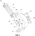
FIG. 2 is a coupled perspective view illustrating the auto tensioner-integrated engine auxiliary device according to the exemplary embodiment of the present disclosure; -
FIG. 3 is an exploded perspective view illustrating the auto tensioner-integrated engine auxiliary device according to the exemplary embodiment of the present disclosure; -
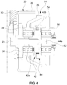
FIG. 4 is a cross-sectional view illustrating an assembled structure of the auto tensioner-integrated engine auxiliary device according to the exemplary embodiment of the present disclosure; -
FIG. 5 is an enlarged view illustrating a configuration of a power transmission unit of the auto tensioner-integrated engine auxiliary device according to the exemplary embodiment of the present disclosure; -
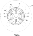
FIG. 6A is a view illustrating an assembled shape of vanes installed between a driving plate and a driven plate of the auto tensioner-integrated engine auxiliary device according to the exemplary embodiment of the present disclosure; -
FIG. 6B is an exemplified view illustrating an operating state of the vanes installed between the driving plate and the driven plate of the auto tensioner-integrated engine auxiliary device according to the exemplary embodiment of the present disclosure; and -
FIG. 7 is a view illustrating a power transmission sequence in accordance with an operation of a power transmission belt of the auto tensioner-integrated engine auxiliary device according to the exemplary embodiment of the present disclosure. - It should be understood that the appended drawings are not necessarily to scale, presenting a somewhat simplified representation of various preferred features illustrative of the basic principles of the invention. The specific design features of the present disclosure as disclosed herein, including, for example, specific dimensions, orientations, locations, and shapes will be determined in part by the particular intended application and use environment.
- In the figures, reference numbers refer to the same or equivalent parts of the present disclosure throughout the several figures of the drawing.
- Hereinafter reference will now be made in detail to various embodiments of the present disclosure, examples of which are illustrated in the accompanying drawings and described below. While the invention will be described in conjunction with exemplary embodiments, it will be understood that present description is not intended to limit the invention to those exemplary embodiments. On the contrary, the invention is intended to cover not only the exemplary embodiments, but also various alternatives, modifications, equivalents and other embodiments, which may be included within the spirit and scope of the invention as defined by the appended claims.
- Hereinafter, an exemplary embodiment of the present disclosure will be described in detail with reference to the accompanying drawings.
- As illustrated in
FIG. 1 , driven pulleys of various types of engine auxiliary devices (a generator, a water pump, or an air-conditioner compressor) are connected to a crankshaft pulley 12 of anengine 10 by apower transmission belt 16 so that the engine auxiliary devices may operate by receiving power from the engine. - That is, the engine auxiliary devices such as the generator, the water pump, and the air-conditioner compressor are configured to be rotationally operated by engine power supplied through the
power transmission belt 16. - In the exemplary embodiment of the present disclosure, the engine auxiliary device integrated with an
auto tensioner 14, which may adjust tension of thepower transmission belt 16 by using awater pump pulley 22 among driven pulleys (i.e., pulley units) of the engine auxiliary devices which are operated by receiving engine power through thepower transmission belt 16, will be described. -
FIG. 1 illustrates a layout and an installed state of the auto tensioner-integrated engine auxiliary devices according to the exemplary embodiment of the present disclosure,FIGS. 2 and3 illustrate a configuration of the auto tensioner-integrated engine auxiliary device according to the exemplary embodiment of the present disclosure,FIG. 4 illustrates an assembled structure of the auto tensioner-integrated engine auxiliary device according to the exemplary embodiment of the present disclosure, andFIG. 5 illustrates an enlarged view of a power transmission unit according to the exemplary embodiment of the present disclosure. - As illustrated in
FIGS. 2 and3 , the auto tensioner-integrated engine auxiliary device according to the present disclosure includes a waterpump pulley part 20, a drivingmember 30, apower transmission unit 40, and awater pump impeller 50. - Referring to
FIG. 1 , the waterpump pulley part 20 is pivotable about apivot shaft 27 by power supplied by the hydraulic drivingmember 30. - The driving
member 30 includes acylinder portion 31 which is extended by supplied hydraulic pressure, and anelastic member 32, which creates restoring force by being deformed, is provided on an outer circumferential surface of thecylinder portion 31. The drivingmember 30 provides power for pivoting the waterpump pulley part 20 while being extended in an axial direction (or a longitudinal direction) by the supplied hydraulic pressure and creates elastic restoring force in accordance with deformation of theelastic member 32. The drivingmember 30 has a structure configured to return the waterpump pulley part 20 by being restored by the elastic restoring force of theelastic member 32 when the hydraulic pressure is eliminated. - One end portion of both end portions in the longitudinal direction of the driving
member 30 is rotatably mounted on the engine (specifically, a cylinder block of the engine), and another end portion thereof is rotatably coupled to asupport bracket 26 of the waterpump pulley part 20. - The
support bracket 26 is mounted between the drivingmember 30 and theengine 10 and pivotable about thepivot shaft 27. An enginecoupling hinge portion 26a, which protrudes from one side of an outer circumferential surface of thesupport bracket 26, is rotatably mounted on theengine 10 by thepivot shaft 27, and a driving membercoupling hinge portion 26b, which protrudes from another side of the outer circumferential surface of thesupport bracket 26, is rotatably fastened to one end portion of the drivingmember 30. - Therefore, the water
pump pulley part 20, which includes thesupport bracket 26 and thewater pump pulley 22, is pivoted about thepivot shaft 27 along an arc by pivoting power provided from the drivingmember 30 when the drivingmember 30 extends. - The water
pump pulley part 20 is provided with arotating shaft 23 and anadapter 24 of thewater pump pulley 22. - The
water pump pulley 22 imparts a predetermined tension to thepower transmission belt 16 while rotating by receiving engine power through thepower transmission belt 16 and while a center of rotation is eccentrically moved by pivoting power provided by the drivingmember 30. Thewater pump pulley 22 is mounted in a movement trajectory of thepower transmission belt 16 so as to be movable by the drivingmember 30, and thewater pump pulley 22 has an outer circumferential surface having a predetermined width so as to be in friction contact with thepower transmission belt 16. - Referring to
FIG. 4 , thewater pump pulley 22 has therotating shaft 23 which is provided at the center of rotation of thewater pump pulley 22 and rotates and pivots simultaneously with thewater pump pulley 22, and therotating shaft 23 is integrally coupled to the center of rotation of thewater pump pulley 22 through theadapter 24. - The rotating
shaft 23 is rotatably coupled to an inner circumferential surface of thesupport bracket 26 by afirst bearing 28, and as a result, thewater pump pulley 22 may pivot, simultaneously with thesupport bracket 26, about thepivot shaft 27 in a state in which thewater pump pulley 22 is stacked on thesupport bracket 26. - The rotating
shaft 23 penetrates thesupport bracket 26 and is integrally coupled to a rotation center (i.e., a shaft coupling portion) of a drivingplate 42 in a press-fit manner, and may rotate and pivot simultaneously with the drivingplate 42. - As illustrated in
FIG. 4 , actually, ashaft coupling portion 42a of the drivingplate 42 and theadapter 24 of thewater pump pulley 22 are fixedly coupled to an inner race of thefirst bearing 28, and as a result, the rotatingshaft 23 is rotatably coupled to the inner circumferential surface of thesupport bracket 26 by thefirst bearing 28. - In more detail, the
adapter 24 and theshaft coupling portion 42a of the drivingplate 42, which are coupled to the outer circumferential surface of therotating shaft 23, are rotatably installed on the inner circumferential surface of thesupport bracket 26 by thefirst bearing 28, and as a result, thewater pump pulley 22 and the drivingplate 42 are supported to be rotatable simultaneously about the rotatingshaft 23. - That is, the
first bearing 28 is mounted on the inner circumferential surface of thesupport bracket 26 and rotatably supports thewater pump pulley 22, the rotatingshaft 23, and the drivingplate 42. - As illustrated in
FIGS. 3 to 5 , thepower transmission unit 40 including the drivingplate 42 includes a drivenplate 44 and a plurality ofvanes 46 as well as the drivingplate 42. - The
power transmission unit 40 allows power to be normally transmitted to thewater pump impeller 50 even though the rotation center of thewater pump pulley 22 is eccentric from a center of rotation thewater pump impeller 50 because of the pivot of the waterpump pulley part 20. - The driven
plate 44 is coupled to a rotating shaft of thewater pump impeller 50, that is, animpeller shaft 52 so as to be rotatable simultaneously with theimpeller shaft 52, the drivingplate 42 is coupled to therotating shaft 23 of thewater pump pulley 22 so as to be rotatable simultaneously with the rotatingshaft 23, and the plurality ofvanes 46 for transmitting power is assembled between the drivenplate 44 and the drivingplate 42. -
Head portions 46a of thevanes 46 are fixedly mounted on an inner circumferential surface of a raisedportion 44b which is formed as an edge portion of one surface of the drivenplate 44 is raised, and ashaft coupling portion 44a, which is coupled to theimpeller shaft 52, is formed at a center of rotation of another surface of the drivenplate 44. - The
vanes 46 are of a pendulum type including thehead portions 46a which are fixedly coupled to the drivenplate 44, andbody portions 46b which are assembled to be linearly movable in movinggrooves 42c provided in the drivingplate 42. Thevanes 46 serve to effectively transmit rotational power of the drivingplate 42 to the drivenplate 44. - In more detail, the
vanes 46 are assembled between the drivingplate 42 and the drivenplate 44 and normally transmit rotational force of the drivingplate 42 to the drivenplate 44 even when thewater pump pulley 22 pivots. In a case in which the rotation center of thewater pump pulley 22 is eccentric from the rotation center of the drivenplate 44, in other words, in a case in which thewater pump pulley 22 is eccentrically moved to adjust tension of thepower transmission belt 16, thevanes 46 allow rotational force of the drivingplate 42 to be effectively transmitted to the driven plate 44 (seeFIGS. 6A and6B ). - To this end, a driving
block 42b, which has the plurality of movinggrooves 42c in which thebody portions 46b of thevanes 46 may slide and linearly move, protrudes from one surface of the drivingplate 42, and thebody portions 46b of thevanes 46 are linearly movably inserted into the plurality of movinggrooves 42c, respectively. - The plurality of moving
grooves 42c is disposed at predetermined intervals along an outer circumferential surface of the drivingblock 42b, and each of the movinggrooves 42c extends in a radial direction from the outer circumferential surface to a center of rotation of the drivingblock 42b. - Since the rotating shaft of the
water pump pulley 22 is rotatably coupled to the center of rotation of the drivingplate 42 in a press-fit manner, the drivingplate 42 is moved simultaneously with thewater pump pulley 22 when thewater pump pulley 22 eccentrically moves. However, even when the drivingplate 42 pivots, the drivingplate 42 and the drivenplate 44 are maintained to be connected by thevanes 46 so as to transmit power, and as a result, the rotational power of the drivingplate 42 is normally transmitted to the drivenplate 44 regardless of the eccentric movement of the drivingplate 42, such that power is transmitted to thewater pump impeller 50. - In this case, in order to allow power to be smoothly transmitted through the
vanes 46, each of thevanes 46 may have aneck portion 46c which is connected between thehead portion 46a and thebody portion 46b and has a narrowed shape. Therefore, when the drivingplate 42 pivots about thepivot shaft 27, thebody portion 46b is resiliently bent relative to thehead portion 46a, such that the connection (the connection for power transmission) between the drivingplate 42 and the drivenplate 44 is maintained (seeFIGS. 6A and6B ). - As illustrated in
FIG. 5 , each of the vane has a structure in which a plate-shapedcore portion 46d, which ensures rigidity and elasticity for power transmission, is inserted into thevane 46 in order to allow the rotational force of the drivingplate 42 to be effectively transmitted to the drivenplate 44 and to smoothly perform the linear movement in the movinggrooves 42c, and an injection moldedportion 46e, which is made of a plastic material and has a lubrication function and elasticity, is formed outside thecore portion 46d by injection molding. - In other words, the
vane 46 includes theinner core portion 46d for ensuring rigidity and elasticity, and the outer injection moldedportion 46e for ensuring linear mobility, and the injection moldedportion 46e is divided into thehead portion 46a, thebody portion 46b, and theneck portion 46c. - The
body portion 46b extends from thehead portion 46a toward the center of the drivenplate 44 with theneck portion 46c interposed between thehead portion 46a and thebody portion 46b, and in this case, thebody portion 46b is formed by injection molding such that a thickness of thebody portion 46b is increased toward the center of the driven plate 44 (in a direction toward the center). - The injection molded
portion 46e serves to provide a lubrication function by using a material characteristic, without using lubricating oil, so that thebody portion 46b of thevane 46 smoothly moves in the movinggroove 42c of the drivingplate 42. - The
impeller shaft 52, which is fixedly coupled to the center of rotation of the drivenplate 44, is rotatably supported by asecond bearing 56 mounted on an inner circumferential surface of awater pump bracket 54, and thewater pump bracket 54 is fixedly mounted on the engine 10 (specifically, the cylinder block of the engine). - The auto tensioner-integrated engine auxiliary device according to the present disclosurewhich is configured as described above, may perform a typical function of the water pump (a function of pumping a coolant) so as to circulate the coolant to be supplied to the engine, and may simultaneously adjust tension of the power transmission belt as necessary.
- Here, a power transmission process in which engine power, which is supplied to the
water pump pulley 22 by the operation of thepower transmission belt 16 connected to thecrank shaft pulley 12 that is rotated by the operation of the engine, is transmitted to thewater pump impeller 50 will be described below with reference toFIGS. 6A to 7 . - Referring to the arrow indicated in
FIG. 7 , the rotational force, which is transmitted to thewater pump pulley 22 by the operation of thepower transmission belt 16, is transmitted to the drivingplate 42 through the rotatingshaft 23 of thewater pump pulley 22, and the rotational force of the drivingplate 42 is transmitted to the drivenplate 44 through thevanes 46, such that the rotational force caused by the operation of thepower transmission belt 16 is transmitted to thewater pump impeller 50 integrally coupled to the drivenplate 44. - In this case, when the driving
plate 42, together with thewater pump pulley 22, pivots about thepivot shaft 27, thevanes 46 are resiliently deformed by being moved in the movinggrooves 42c so that the drivingplate 42 is pivotable, and thevanes 46 simultaneously maintains the connection state for power transmission between the drivingplate 42 and the drivenplate 44, as illustrated inFIGS. 6A and6B , and as a result, the rotational force of the drivingplate 42 is effectively transmitted to the drivenplate 44, and thewater pump impeller 50 normally rotates, such that the engine coolant is normally circulated by the rotation of thewater pump impeller 50. - As described above, according to the auto tensioner-integrated engine auxiliary device according to the present disclosure, since the
power transmission unit 40 may transmit the rotational force of the drivingplate 42 to the drivenplate 44 through thevanes 46 assembled between the drivingplate 42 and the drivenplate 44 regardless of the pivot of the drivingplate 42 that moves integrally with thewater pump pulley 22, it is possible to adjust tension of thepower transmission belt 16 by pivoting thewater pump pulley 22 and to simultaneously perform the function of the water pump which circulates the engine coolant by rotating thewater pump impeller 50. - Since the function of adjusting tension of the
power transmission belt 16 is performed by using thewater pump pulley 22, it is possible to omit a tensioner pulley that was used to adjust tension of the existing power transmission belt, reduce a size of a package, increase a mounting space, reduce a length of the power transmission belt, reduce costs and a weight, and improve fuel economy. In addition, it is possible to implement a compact and simple layout of the power transmission belt to which the engine auxiliary device and the auto tensioner are applied. - Hereinafter, the auto tensioner according to the exemplary embodiment of the present disclosure will be described, and because the description associated with the
auto tensioner 14 according to the present disclosure is included in the aforementioned description associated with the auto tensioner-integrated engine auxiliary device (water pump), some of descriptions associated with theauto tensioner 14 will be omitted. - The
auto tensioner 14 according to the exemplary embodiment of the present disclosure is configured to adjust tension of thepower transmission belt 16 by utilizing the driven pulley of the water pump (i.e., the water pump pulley) of the engine auxiliary device which is rotated by engine power transmitted through thepower transmission belt 16, and theauto tensioner 14 is mounted on therotating shaft 23 of thewater pump pulley 22, which is a pulley unit of the water pump, and pivoting about thepivot shaft 27. - The rotating
shaft 23 is coupled to the center of rotation of thewater pump pulley 22 so as to be rotatable simultaneously with thewater pump pulley 22, and rotates together with thewater pump pulley 22 when thewater pump pulley 22 rotates by power transmitted through thepower transmission belt 16. - The
auto tensioner 14 includes thesupport bracket 26 which has one side rotatably fastened to thepivot shaft 27 and another side fastened to the drivingmember 30 and may pivot about thepivot shaft 27 in accordance with the operation of the drivingmember 30, and theauto tensioner 14 is provided with thepower transmission unit 40 so that power of therotating shaft 23 may be transmitted to thewater pump impeller 50 which is an output unit of the water pump. - As illustrated in
FIG. 4 , thesupport bracket 26 is mounted on therotating shaft 23 by thefirst bearing 28 which may rotate relative to therotating shaft 23, and thesupport bracket 26, which is mounted on therotating shaft 23 as described above, is supported to be pivotable about thepivot shaft 27 by thepower transmission unit 40 having a structure including thevanes 46. - The
power transmission unit 40 includes the drivingplate 42 which is coupled to therotating shaft 23 and receives power, the drivenplate 44 which rotates by receiving rotational force of the drivingplate 42, and the plurality ofvanes 46 which transmits the rotational force of the drivingplate 42 to the drivenplate 44. - Here, the
vane 46 may be formed to have the aforementioned structure, and thewater pump impeller 50, which is the output unit of the water pump, rotates by receiving rotational power of therotating shaft 23 by thepower transmission unit 40. - A first further preferred embodiment of the present invention is an auto tensioner-integrated engine auxiliary device comprising: a pulley unit which rotates by a power transmitted through a power transmission belt; a rotating shaft which is coupled to a center of the pulley unit and rotates simultaneously with the pulley unit; an output unit which rotates by receiving the power of the rotating shaft; and an auto tensioner which operates such that the rotating shaft pivots about a pivot shaft.
- In a first aspect of the first further preferred embodiment of the present invention, the auto tensioner is mounted on the rotating shaft by a bearing that is rotatable relative to the rotating shaft.
- In a second aspect of the first further preferred embodiment of the present invention, either alone or in combination with the first aspect of the first further preferred embodiment of the present invention, the auto tensioner has one side rotatably fastened to the pivot shaft and another side fastened to a driving member, and pivots about the pivot shaft in accordance with an operation of the driving member. Said driving member may include: a cylinder portion that is operated by hydraulic pressure; and an elastic member, which provides restoring force when the hydraulic pressure is eliminated, is disposed on an outer circumferential surface of the cylinder portion.
- In a third aspect of the first further preferred embodiment of the present invention, either alone or in any combination with the first and second aspects of the first further preferred embodiment of the present invention, said auto tensioner-integrated engine auxiliary device further comprises: a driving plate which is coupled to the rotating shaft and receives the power; and a driven plate which rotates by receiving a rotational force of the driving plate, wherein a plurality of vanes, which transmit the rotational force of the driving plate to the driven plate even when the rotating shaft pivots, are disposed on the driven plate. Each of said vanes may include: a head portion which is fixed to an edge portion of the driven plate; and a body portion which extends from the head portion toward a center of the driven plate, and a driving block, which has moving grooves in which the body portion is accommodated, may be disposed on the driving plate. Further, a core portion may be inserted into the vanes, and a thickness of the body portion may be increased in a direction toward a center of the driven plate.
- In a fourth aspect of the first further preferred embodiment of the present invention, either alone or in any combination with the first to third aspects of the first further preferred embodiment of the present invention, the pulley unit is a water pump pulley, and the output unit is a water pump impeller.
- A second further preferred embodiment of the present invention is an auto tensioner-integrated engine auxiliary device comprising: a water pump pulley which adjusts tension of a power transmission belt by pivoting about a pivot shaft and simultaneously rotates about a rotating shaft by a power transmitted through the power transmission belt; and a power transmission unit which transmits rotational power of the water pump pulley, which rotates about the rotating shaft, to a water pump impeller.
- In a first aspect of the second further preferred embodiment of the present invention, the water pump pulley is coupled to an inner circumferential surface of a support bracket so as to be rotatable simultaneously with the rotating shaft, and the support bracket has: a driving member coupling hinge portion coupled to a driving member; and an engine coupling hinge portion mounted on an engine to be rotatable about the pivot shaft.
- In a second aspect of the second further preferred embodiment of the present invention, either alone or in combination with the first aspect of the second further preferred embodiment of the present invention, the power transmission unit includes: a driving plate which is coupled to the water pump pulley to be rotatable and pivotable integrally with the water pump pulley; a driven plate which is coupled to the water pump impeller so as to be rotatable simultaneously with the water pump impeller and rotates by receiving a rotational force of the driving plate; and a plurality of vanes which are assembled between the driving plate and the driven plate and transmit the rotational force of the driving plate to the driven plate even when the water pump pulley pivots.
- Said vanes described in the second aspect of the second further preferred embodiment of the present invention may include: a head portion which is fixed to the driven plate; and a body portion which is assembled to be linearly movable in a moving groove provided in the driving plate.
- Said vanes described in the second aspect of the second further preferred embodiment of the present invention may additionally have a neck portion which is connected between the head portion and the body portion and has a narrowed shape, such that when the driving plate pivots about the pivot shaft, the body portion is resiliently bendable relative to the head portion. A driving block, which has a plurality of moving grooves, may be provided on the driving plate, and the moving grooves may extend in a radial direction from an outer circumferential surface of the driving block.
- The invention has been described in detail with reference to preferred embodiments thereof. However, it will be appreciated by those skilled in the art that changes may be made in these embodiments without departing from the principles and spirit of the invention, the scope of which is defined in the appended claims and their equivalents.
Claims (6)
- An auto tensioner which is mounted on a rotating shaft of an engine auxiliary device rotating about the rotating shaft by a power transmitted through a power transmission belt, the auto tensioner pivoting about a pivot shaft.
- The auto tensioner of claim 1, wherein the auto tensioner has one side rotatably fastened to the pivot shaft and another side fastened to a driving member, and pivots about the pivot shaft in accordance with an operation of the driving member.
- The auto tensioner of claim 2, wherein the driving member includes: a cylinder portion that is operated by hydraulic pressure; and an elastic member, which provides restoring force when the hydraulic pressure is eliminated, is disposed on an outer circumferential surface of the cylinder portion.
- The auto tensioner of any one of claims 1 to 3, further comprising:a driving plate which is coupled to the rotating shaft and receives the power; anda driven plate which rotates by receiving a rotational force of the driving plate,wherein a plurality of vanes, which transmit the rotational force of the driving plate to the driven plate, are disposed on the driven plate.
- The auto tensioner of claim 4, wherein the vanes include: a head portion which is fixed to an edge portion of the driven plate; and a body portion which extends from the head portion toward a center of the driven plate, and
wherein a driving block, which has moving grooves in which the body portion is accommodated, is formed on the driving plate. - The auto tensioner of claim 4 or 5, wherein a core portion is inserted into the vanes, and
wherein a thickness of the body portion is increased in a direction toward a center of the driven plate.
Applications Claiming Priority (1)
| Application Number | Priority Date | Filing Date | Title |
|---|---|---|---|
| KR1020160094482A KR101795289B1 (en) | 2016-07-26 | 2016-07-26 | Auto tensioner and engine auxiliary machinery having auto tensioner |
Publications (2)
| Publication Number | Publication Date |
|---|---|
| EP3276204A1 true EP3276204A1 (en) | 2018-01-31 |
| EP3276204B1 EP3276204B1 (en) | 2019-03-20 |
Family
ID=57737599
Family Applications (1)
| Application Number | Title | Priority Date | Filing Date |
|---|---|---|---|
| EP16206785.4A Not-in-force EP3276204B1 (en) | 2016-07-26 | 2016-12-23 | Auto tensioner and auto tensioner-integrated engine auxiliary device |
Country Status (4)
| Country | Link |
|---|---|
| US (1) | US10508719B2 (en) |
| EP (1) | EP3276204B1 (en) |
| KR (1) | KR101795289B1 (en) |
| CN (1) | CN107654595B (en) |
Families Citing this family (4)
| Publication number | Priority date | Publication date | Assignee | Title |
|---|---|---|---|---|
| DE102017003156A1 (en) * | 2017-03-31 | 2018-10-04 | Süddeutsche Gelenkscheibenfabrik GmbH & Co. KG | Vibration-decoupled pulley |
| USD900160S1 (en) * | 2018-08-02 | 2020-10-27 | Holley Performance Products, Inc. | Power steering pump bracket |
| DE102020205971A1 (en) * | 2020-05-12 | 2021-11-18 | Zf Automotive Germany Gmbh | Pulley and steering gear |
| EP4423407B1 (en) * | 2021-10-29 | 2026-01-28 | Gates Corporation | Bearing pivot tensioner assembly |
Citations (4)
| Publication number | Priority date | Publication date | Assignee | Title |
|---|---|---|---|---|
| DE19632167A1 (en) * | 1996-08-09 | 1998-02-12 | Fag Automobiltechnik Ag | Unit consisting of an electric motor and a driven machine driven by it |
| WO2006037433A1 (en) * | 2004-10-05 | 2006-04-13 | Schaeffler Kg | Device for securing and tensing a unit which can be inserted into a belt drive |
| DE102008011136A1 (en) * | 2008-02-26 | 2009-08-27 | Schaeffler Kg | Mounting device for a clamping system |
| US20110135444A1 (en) * | 2009-12-04 | 2011-06-09 | Hyundai Motor Company | Water pump for vehicle |
Family Cites Families (21)
| Publication number | Priority date | Publication date | Assignee | Title |
|---|---|---|---|---|
| DE3208184C1 (en) * | 1982-03-06 | 1983-10-06 | Daimler Benz Ag | Tensioning device for a sleeve drive, in particular a belt drive |
| US4563167A (en) * | 1982-09-29 | 1986-01-07 | Dayco Corporation | Belt tensioner and method of making the same |
| US4822321A (en) | 1988-07-18 | 1989-04-18 | General Motors Corporation | Combination water pump and belt tensioner |
| FR2689590B1 (en) * | 1992-04-06 | 1998-04-30 | Hutchinson | AUTOMATIC TENSIONER FOR BELT, PARTICULARLY FOR SYNCHRONOUS TRANSMISSION BELT, SUCH AS A TIMING BELT. |
| US5918717A (en) * | 1996-09-27 | 1999-07-06 | Foehl; Artur | Rotary drive apparatus for a belt tensioner |
| CN1643272A (en) | 2002-03-15 | 2005-07-20 | 盖茨公司 | Initial belt tensioner |
| KR100535609B1 (en) | 2003-09-09 | 2005-12-08 | 현대자동차주식회사 | Drive belt system |
| KR20050062052A (en) | 2003-12-19 | 2005-06-23 | 현대자동차주식회사 | Connecting structure of auto-tensioner in a car |
| JP2006077941A (en) | 2004-09-13 | 2006-03-23 | Jtekt Corp | Power transmission device |
| US7494434B2 (en) * | 2005-06-15 | 2009-02-24 | Gm Global Technology Operations, Inc. | Belt alternator starter accessory drive with dual tensioner |
| US20100210385A1 (en) * | 2009-02-16 | 2010-08-19 | Gm Global Technology Operations, Inc. | Tensioner assembly for a rotary drive |
| US8568259B2 (en) * | 2009-09-11 | 2013-10-29 | GM Global Technology Operations LLC | Engine accessory drive with belt tensioner and same plane idler |
| US8602930B2 (en) * | 2009-09-18 | 2013-12-10 | GM Global Technology Operations LLC | Drive belt tensioner for motor generator unit |
| US8057334B2 (en) * | 2009-09-23 | 2011-11-15 | GM Global Technology Operations LLC | Accessory drive tensioner assembly |
| KR101273873B1 (en) | 2011-10-27 | 2013-06-11 | 지엠 글로벌 테크놀러지 오퍼레이션스 엘엘씨 | FEAD Auto-Tensioner having a housing of which the inner shape is oval |
| JP2013170673A (en) | 2012-02-22 | 2013-09-02 | Toyota Motor Corp | Power transmission mechanism |
| JP2013249939A (en) * | 2012-06-04 | 2013-12-12 | Tsubakimoto Chain Co | Hydraulic tensioner |
| DE102013102562B4 (en) * | 2013-03-13 | 2021-05-27 | Muhr Und Bender Kg | Use of a spring in a belt tensioning device, belt tensioning device and assembly arrangement |
| EP3209901B1 (en) * | 2014-10-21 | 2022-04-20 | Litens Automotive Partnership | Endless drive arrangement and improved two-armed tensioning system for same |
| CN107614918B (en) * | 2015-06-03 | 2020-04-28 | 利滕斯汽车合伙公司 | Improved isolator |
| US10018254B2 (en) * | 2016-05-27 | 2018-07-10 | GM Global Technology Operations LLC | Belt drive system for an internal combustion engine |
-
2016
- 2016-07-26 KR KR1020160094482A patent/KR101795289B1/en not_active Expired - Fee Related
- 2016-12-08 US US15/373,149 patent/US10508719B2/en active Active
- 2016-12-15 CN CN201611158115.9A patent/CN107654595B/en not_active Expired - Fee Related
- 2016-12-23 EP EP16206785.4A patent/EP3276204B1/en not_active Not-in-force
Patent Citations (4)
| Publication number | Priority date | Publication date | Assignee | Title |
|---|---|---|---|---|
| DE19632167A1 (en) * | 1996-08-09 | 1998-02-12 | Fag Automobiltechnik Ag | Unit consisting of an electric motor and a driven machine driven by it |
| WO2006037433A1 (en) * | 2004-10-05 | 2006-04-13 | Schaeffler Kg | Device for securing and tensing a unit which can be inserted into a belt drive |
| DE102008011136A1 (en) * | 2008-02-26 | 2009-08-27 | Schaeffler Kg | Mounting device for a clamping system |
| US20110135444A1 (en) * | 2009-12-04 | 2011-06-09 | Hyundai Motor Company | Water pump for vehicle |
Also Published As
| Publication number | Publication date |
|---|---|
| CN107654595B (en) | 2021-04-02 |
| US20180031086A1 (en) | 2018-02-01 |
| CN107654595A (en) | 2018-02-02 |
| EP3276204B1 (en) | 2019-03-20 |
| US10508719B2 (en) | 2019-12-17 |
| KR101795289B1 (en) | 2017-11-07 |
Similar Documents
| Publication | Publication Date | Title |
|---|---|---|
| EP3276204B1 (en) | Auto tensioner and auto tensioner-integrated engine auxiliary device | |
| CN114207317B (en) | Track tensioner | |
| US10865858B2 (en) | Belt tensioner | |
| US8714943B2 (en) | Mounting and damping system for a compressor | |
| US20190063491A1 (en) | Air foil bearing assembly | |
| CN109899390B (en) | Air foil bearing assembly | |
| JP2019019982A (en) | Belt tensioning device | |
| US8919317B2 (en) | Inertia incremental apparatus for flywheel of engine | |
| JP2000170642A (en) | Radial piston pump | |
| CN1372622A (en) | Power transmission mechanism | |
| US10295027B2 (en) | Power transmission roller assembly | |
| US10619712B2 (en) | Tensioner mounting structure for vehicle | |
| CN106321215B (en) | Fan drives for motor vehicles | |
| US20160069335A1 (en) | Hybrid compressor | |
| CN110925330B (en) | Clutch master cylinder and vehicle | |
| US20070194655A1 (en) | Automotive AC generator designed to establish shaft-to-shaft connection with engine | |
| JP2011094763A (en) | Electric power steering device | |
| KR100871262B1 (en) | Reciprocating piston mechanism with articulated connection | |
| CN111577453B (en) | Design method of engine accessory driving system | |
| US11162564B2 (en) | Pendulum-type accessary tensioner | |
| JP6752663B2 (en) | Electric actuator | |
| JP2007232164A (en) | Torque transmitting apparatus | |
| JP2003286978A5 (en) | ||
| US20160169123A1 (en) | High pressure fuel supplying apparatus of engine | |
| EP1279808B1 (en) | Mechanism for actuating auxiliary device of internal combustion engines |
Legal Events
| Date | Code | Title | Description |
|---|---|---|---|
| PUAI | Public reference made under article 153(3) epc to a published international application that has entered the european phase |
Free format text: ORIGINAL CODE: 0009012 |
|
| STAA | Information on the status of an ep patent application or granted ep patent |
Free format text: STATUS: THE APPLICATION HAS BEEN PUBLISHED |
|
| AK | Designated contracting states |
Kind code of ref document: A1 Designated state(s): AL AT BE BG CH CY CZ DE DK EE ES FI FR GB GR HR HU IE IS IT LI LT LU LV MC MK MT NL NO PL PT RO RS SE SI SK SM TR |
|
| AX | Request for extension of the european patent |
Extension state: BA ME |
|
| STAA | Information on the status of an ep patent application or granted ep patent |
Free format text: STATUS: REQUEST FOR EXAMINATION WAS MADE |
|
| 17P | Request for examination filed |
Effective date: 20180730 |
|
| RBV | Designated contracting states (corrected) |
Designated state(s): AL AT BE BG CH CY CZ DE DK EE ES FI FR GB GR HR HU IE IS IT LI LT LU LV MC MK MT NL NO PL PT RO RS SE SI SK SM TR |
|
| RIC1 | Information provided on ipc code assigned before grant |
Ipc: F16H 7/14 20060101AFI20180828BHEP Ipc: F16H 39/00 20060101ALI20180828BHEP |
|
| GRAP | Despatch of communication of intention to grant a patent |
Free format text: ORIGINAL CODE: EPIDOSNIGR1 |
|
| STAA | Information on the status of an ep patent application or granted ep patent |
Free format text: STATUS: GRANT OF PATENT IS INTENDED |
|
| INTG | Intention to grant announced |
Effective date: 20181008 |
|
| GRAS | Grant fee paid |
Free format text: ORIGINAL CODE: EPIDOSNIGR3 |
|
| GRAA | (expected) grant |
Free format text: ORIGINAL CODE: 0009210 |
|
| STAA | Information on the status of an ep patent application or granted ep patent |
Free format text: STATUS: THE PATENT HAS BEEN GRANTED |
|
| AK | Designated contracting states |
Kind code of ref document: B1 Designated state(s): AL AT BE BG CH CY CZ DE DK EE ES FI FR GB GR HR HU IE IS IT LI LT LU LV MC MK MT NL NO PL PT RO RS SE SI SK SM TR |
|
| REG | Reference to a national code |
Ref country code: GB Ref legal event code: FG4D |
|
| REG | Reference to a national code |
Ref country code: CH Ref legal event code: EP |
|
| REG | Reference to a national code |
Ref country code: DE Ref legal event code: R096 Ref document number: 602016011264 Country of ref document: DE |
|
| REG | Reference to a national code |
Ref country code: AT Ref legal event code: REF Ref document number: 1110895 Country of ref document: AT Kind code of ref document: T Effective date: 20190415 |
|
| REG | Reference to a national code |
Ref country code: IE Ref legal event code: FG4D |
|
| REG | Reference to a national code |
Ref country code: NL Ref legal event code: MP Effective date: 20190320 |
|
| PG25 | Lapsed in a contracting state [announced via postgrant information from national office to epo] |
Ref country code: NO Free format text: LAPSE BECAUSE OF FAILURE TO SUBMIT A TRANSLATION OF THE DESCRIPTION OR TO PAY THE FEE WITHIN THE PRESCRIBED TIME-LIMIT Effective date: 20190620 Ref country code: LT Free format text: LAPSE BECAUSE OF FAILURE TO SUBMIT A TRANSLATION OF THE DESCRIPTION OR TO PAY THE FEE WITHIN THE PRESCRIBED TIME-LIMIT Effective date: 20190320 Ref country code: FI Free format text: LAPSE BECAUSE OF FAILURE TO SUBMIT A TRANSLATION OF THE DESCRIPTION OR TO PAY THE FEE WITHIN THE PRESCRIBED TIME-LIMIT Effective date: 20190320 Ref country code: SE Free format text: LAPSE BECAUSE OF FAILURE TO SUBMIT A TRANSLATION OF THE DESCRIPTION OR TO PAY THE FEE WITHIN THE PRESCRIBED TIME-LIMIT Effective date: 20190320 |
|
| REG | Reference to a national code |
Ref country code: LT Ref legal event code: MG4D |
|
| PG25 | Lapsed in a contracting state [announced via postgrant information from national office to epo] |
Ref country code: LV Free format text: LAPSE BECAUSE OF FAILURE TO SUBMIT A TRANSLATION OF THE DESCRIPTION OR TO PAY THE FEE WITHIN THE PRESCRIBED TIME-LIMIT Effective date: 20190320 Ref country code: NL Free format text: LAPSE BECAUSE OF FAILURE TO SUBMIT A TRANSLATION OF THE DESCRIPTION OR TO PAY THE FEE WITHIN THE PRESCRIBED TIME-LIMIT Effective date: 20190320 Ref country code: HR Free format text: LAPSE BECAUSE OF FAILURE TO SUBMIT A TRANSLATION OF THE DESCRIPTION OR TO PAY THE FEE WITHIN THE PRESCRIBED TIME-LIMIT Effective date: 20190320 Ref country code: GR Free format text: LAPSE BECAUSE OF FAILURE TO SUBMIT A TRANSLATION OF THE DESCRIPTION OR TO PAY THE FEE WITHIN THE PRESCRIBED TIME-LIMIT Effective date: 20190621 Ref country code: BG Free format text: LAPSE BECAUSE OF FAILURE TO SUBMIT A TRANSLATION OF THE DESCRIPTION OR TO PAY THE FEE WITHIN THE PRESCRIBED TIME-LIMIT Effective date: 20190620 Ref country code: RS Free format text: LAPSE BECAUSE OF FAILURE TO SUBMIT A TRANSLATION OF THE DESCRIPTION OR TO PAY THE FEE WITHIN THE PRESCRIBED TIME-LIMIT Effective date: 20190320 |
|
| REG | Reference to a national code |
Ref country code: AT Ref legal event code: MK05 Ref document number: 1110895 Country of ref document: AT Kind code of ref document: T Effective date: 20190320 |
|
| PG25 | Lapsed in a contracting state [announced via postgrant information from national office to epo] |
Ref country code: EE Free format text: LAPSE BECAUSE OF FAILURE TO SUBMIT A TRANSLATION OF THE DESCRIPTION OR TO PAY THE FEE WITHIN THE PRESCRIBED TIME-LIMIT Effective date: 20190320 Ref country code: ES Free format text: LAPSE BECAUSE OF FAILURE TO SUBMIT A TRANSLATION OF THE DESCRIPTION OR TO PAY THE FEE WITHIN THE PRESCRIBED TIME-LIMIT Effective date: 20190320 Ref country code: CZ Free format text: LAPSE BECAUSE OF FAILURE TO SUBMIT A TRANSLATION OF THE DESCRIPTION OR TO PAY THE FEE WITHIN THE PRESCRIBED TIME-LIMIT Effective date: 20190320 Ref country code: IT Free format text: LAPSE BECAUSE OF FAILURE TO SUBMIT A TRANSLATION OF THE DESCRIPTION OR TO PAY THE FEE WITHIN THE PRESCRIBED TIME-LIMIT Effective date: 20190320 Ref country code: RO Free format text: LAPSE BECAUSE OF FAILURE TO SUBMIT A TRANSLATION OF THE DESCRIPTION OR TO PAY THE FEE WITHIN THE PRESCRIBED TIME-LIMIT Effective date: 20190320 Ref country code: SK Free format text: LAPSE BECAUSE OF FAILURE TO SUBMIT A TRANSLATION OF THE DESCRIPTION OR TO PAY THE FEE WITHIN THE PRESCRIBED TIME-LIMIT Effective date: 20190320 Ref country code: PT Free format text: LAPSE BECAUSE OF FAILURE TO SUBMIT A TRANSLATION OF THE DESCRIPTION OR TO PAY THE FEE WITHIN THE PRESCRIBED TIME-LIMIT Effective date: 20190720 Ref country code: AL Free format text: LAPSE BECAUSE OF FAILURE TO SUBMIT A TRANSLATION OF THE DESCRIPTION OR TO PAY THE FEE WITHIN THE PRESCRIBED TIME-LIMIT Effective date: 20190320 |
|
| PG25 | Lapsed in a contracting state [announced via postgrant information from national office to epo] |
Ref country code: SM Free format text: LAPSE BECAUSE OF FAILURE TO SUBMIT A TRANSLATION OF THE DESCRIPTION OR TO PAY THE FEE WITHIN THE PRESCRIBED TIME-LIMIT Effective date: 20190320 Ref country code: PL Free format text: LAPSE BECAUSE OF FAILURE TO SUBMIT A TRANSLATION OF THE DESCRIPTION OR TO PAY THE FEE WITHIN THE PRESCRIBED TIME-LIMIT Effective date: 20190320 |
|
| PG25 | Lapsed in a contracting state [announced via postgrant information from national office to epo] |
Ref country code: IS Free format text: LAPSE BECAUSE OF FAILURE TO SUBMIT A TRANSLATION OF THE DESCRIPTION OR TO PAY THE FEE WITHIN THE PRESCRIBED TIME-LIMIT Effective date: 20190720 Ref country code: AT Free format text: LAPSE BECAUSE OF FAILURE TO SUBMIT A TRANSLATION OF THE DESCRIPTION OR TO PAY THE FEE WITHIN THE PRESCRIBED TIME-LIMIT Effective date: 20190320 |
|
| REG | Reference to a national code |
Ref country code: DE Ref legal event code: R097 Ref document number: 602016011264 Country of ref document: DE |
|
| PLBE | No opposition filed within time limit |
Free format text: ORIGINAL CODE: 0009261 |
|
| STAA | Information on the status of an ep patent application or granted ep patent |
Free format text: STATUS: NO OPPOSITION FILED WITHIN TIME LIMIT |
|
| PG25 | Lapsed in a contracting state [announced via postgrant information from national office to epo] |
Ref country code: DK Free format text: LAPSE BECAUSE OF FAILURE TO SUBMIT A TRANSLATION OF THE DESCRIPTION OR TO PAY THE FEE WITHIN THE PRESCRIBED TIME-LIMIT Effective date: 20190320 |
|
| 26N | No opposition filed |
Effective date: 20200102 |
|
| PG25 | Lapsed in a contracting state [announced via postgrant information from national office to epo] |
Ref country code: SI Free format text: LAPSE BECAUSE OF FAILURE TO SUBMIT A TRANSLATION OF THE DESCRIPTION OR TO PAY THE FEE WITHIN THE PRESCRIBED TIME-LIMIT Effective date: 20190320 |
|
| PG25 | Lapsed in a contracting state [announced via postgrant information from national office to epo] |
Ref country code: TR Free format text: LAPSE BECAUSE OF FAILURE TO SUBMIT A TRANSLATION OF THE DESCRIPTION OR TO PAY THE FEE WITHIN THE PRESCRIBED TIME-LIMIT Effective date: 20190320 |
|
| REG | Reference to a national code |
Ref country code: CH Ref legal event code: PL |
|
| REG | Reference to a national code |
Ref country code: BE Ref legal event code: MM Effective date: 20191231 |
|
| PG25 | Lapsed in a contracting state [announced via postgrant information from national office to epo] |
Ref country code: MC Free format text: LAPSE BECAUSE OF FAILURE TO SUBMIT A TRANSLATION OF THE DESCRIPTION OR TO PAY THE FEE WITHIN THE PRESCRIBED TIME-LIMIT Effective date: 20190320 |
|
| PG25 | Lapsed in a contracting state [announced via postgrant information from national office to epo] |
Ref country code: IE Free format text: LAPSE BECAUSE OF NON-PAYMENT OF DUE FEES Effective date: 20191223 Ref country code: LU Free format text: LAPSE BECAUSE OF NON-PAYMENT OF DUE FEES Effective date: 20191223 |
|
| PG25 | Lapsed in a contracting state [announced via postgrant information from national office to epo] |
Ref country code: CH Free format text: LAPSE BECAUSE OF NON-PAYMENT OF DUE FEES Effective date: 20191231 Ref country code: BE Free format text: LAPSE BECAUSE OF NON-PAYMENT OF DUE FEES Effective date: 20191231 Ref country code: LI Free format text: LAPSE BECAUSE OF NON-PAYMENT OF DUE FEES Effective date: 20191231 |
|
| PG25 | Lapsed in a contracting state [announced via postgrant information from national office to epo] |
Ref country code: CY Free format text: LAPSE BECAUSE OF FAILURE TO SUBMIT A TRANSLATION OF THE DESCRIPTION OR TO PAY THE FEE WITHIN THE PRESCRIBED TIME-LIMIT Effective date: 20190320 |
|
| PG25 | Lapsed in a contracting state [announced via postgrant information from national office to epo] |
Ref country code: MT Free format text: LAPSE BECAUSE OF FAILURE TO SUBMIT A TRANSLATION OF THE DESCRIPTION OR TO PAY THE FEE WITHIN THE PRESCRIBED TIME-LIMIT Effective date: 20190320 Ref country code: HU Free format text: LAPSE BECAUSE OF FAILURE TO SUBMIT A TRANSLATION OF THE DESCRIPTION OR TO PAY THE FEE WITHIN THE PRESCRIBED TIME-LIMIT; INVALID AB INITIO Effective date: 20161223 |
|
| PG25 | Lapsed in a contracting state [announced via postgrant information from national office to epo] |
Ref country code: MK Free format text: LAPSE BECAUSE OF FAILURE TO SUBMIT A TRANSLATION OF THE DESCRIPTION OR TO PAY THE FEE WITHIN THE PRESCRIBED TIME-LIMIT Effective date: 20190320 |
|
| PGFP | Annual fee paid to national office [announced via postgrant information from national office to epo] |
Ref country code: GB Payment date: 20221121 Year of fee payment: 7 Ref country code: FR Payment date: 20221121 Year of fee payment: 7 Ref country code: DE Payment date: 20220621 Year of fee payment: 7 |
|
| P01 | Opt-out of the competence of the unified patent court (upc) registered |
Effective date: 20230522 |
|
| REG | Reference to a national code |
Ref country code: DE Ref legal event code: R119 Ref document number: 602016011264 Country of ref document: DE |
|
| GBPC | Gb: european patent ceased through non-payment of renewal fee |
Effective date: 20231223 |
|
| PG25 | Lapsed in a contracting state [announced via postgrant information from national office to epo] |
Ref country code: DE Free format text: LAPSE BECAUSE OF NON-PAYMENT OF DUE FEES Effective date: 20240702 |
|
| PG25 | Lapsed in a contracting state [announced via postgrant information from national office to epo] |
Ref country code: GB Free format text: LAPSE BECAUSE OF NON-PAYMENT OF DUE FEES Effective date: 20231223 |
|
| PG25 | Lapsed in a contracting state [announced via postgrant information from national office to epo] |
Ref country code: FR Free format text: LAPSE BECAUSE OF NON-PAYMENT OF DUE FEES Effective date: 20231231 |
|
| PG25 | Lapsed in a contracting state [announced via postgrant information from national office to epo] |
Ref country code: GB Free format text: LAPSE BECAUSE OF NON-PAYMENT OF DUE FEES Effective date: 20231223 Ref country code: FR Free format text: LAPSE BECAUSE OF NON-PAYMENT OF DUE FEES Effective date: 20231231 Ref country code: DE Free format text: LAPSE BECAUSE OF NON-PAYMENT OF DUE FEES Effective date: 20240702 |