EP3276199A1 - Brake caliper - Google Patents
Brake caliper Download PDFInfo
- Publication number
- EP3276199A1 EP3276199A1 EP17000877.5A EP17000877A EP3276199A1 EP 3276199 A1 EP3276199 A1 EP 3276199A1 EP 17000877 A EP17000877 A EP 17000877A EP 3276199 A1 EP3276199 A1 EP 3276199A1
- Authority
- EP
- European Patent Office
- Prior art keywords
- seat
- linkage
- brake
- hole
- fixing
- Prior art date
- Legal status (The legal status is an assumption and is not a legal conclusion. Google has not performed a legal analysis and makes no representation as to the accuracy of the status listed.)
- Granted
Links
- 230000004308 accommodation Effects 0.000 claims abstract description 26
- 239000012530 fluid Substances 0.000 description 6
- 238000004891 communication Methods 0.000 description 1
- 238000009434 installation Methods 0.000 description 1
- 238000012986 modification Methods 0.000 description 1
- 230000004048 modification Effects 0.000 description 1
Images





Classifications
-
- F—MECHANICAL ENGINEERING; LIGHTING; HEATING; WEAPONS; BLASTING
- F16—ENGINEERING ELEMENTS AND UNITS; GENERAL MEASURES FOR PRODUCING AND MAINTAINING EFFECTIVE FUNCTIONING OF MACHINES OR INSTALLATIONS; THERMAL INSULATION IN GENERAL
- F16D—COUPLINGS FOR TRANSMITTING ROTATION; CLUTCHES; BRAKES
- F16D65/00—Parts or details
- F16D65/005—Components of axially engaging brakes not otherwise provided for
- F16D65/0068—Brake calipers
- F16D65/0075—Brake calipers assembled from a plurality of parts
-
- B—PERFORMING OPERATIONS; TRANSPORTING
- B60—VEHICLES IN GENERAL
- B60T—VEHICLE BRAKE CONTROL SYSTEMS OR PARTS THEREOF; BRAKE CONTROL SYSTEMS OR PARTS THEREOF, IN GENERAL; ARRANGEMENT OF BRAKING ELEMENTS ON VEHICLES IN GENERAL; PORTABLE DEVICES FOR PREVENTING UNWANTED MOVEMENT OF VEHICLES; VEHICLE MODIFICATIONS TO FACILITATE COOLING OF BRAKES
- B60T13/00—Transmitting braking action from initiating means to ultimate brake actuator with power assistance or drive; Brake systems incorporating such transmitting means, e.g. air-pressure brake systems
- B60T13/10—Transmitting braking action from initiating means to ultimate brake actuator with power assistance or drive; Brake systems incorporating such transmitting means, e.g. air-pressure brake systems with fluid assistance, drive, or release
- B60T13/58—Combined or convertible systems
- B60T13/588—Combined or convertible systems both fluid and mechanical assistance or drive
-
- B—PERFORMING OPERATIONS; TRANSPORTING
- B60—VEHICLES IN GENERAL
- B60T—VEHICLE BRAKE CONTROL SYSTEMS OR PARTS THEREOF; BRAKE CONTROL SYSTEMS OR PARTS THEREOF, IN GENERAL; ARRANGEMENT OF BRAKING ELEMENTS ON VEHICLES IN GENERAL; PORTABLE DEVICES FOR PREVENTING UNWANTED MOVEMENT OF VEHICLES; VEHICLE MODIFICATIONS TO FACILITATE COOLING OF BRAKES
- B60T13/00—Transmitting braking action from initiating means to ultimate brake actuator with power assistance or drive; Brake systems incorporating such transmitting means, e.g. air-pressure brake systems
- B60T13/74—Transmitting braking action from initiating means to ultimate brake actuator with power assistance or drive; Brake systems incorporating such transmitting means, e.g. air-pressure brake systems with electrical assistance or drive
- B60T13/741—Transmitting braking action from initiating means to ultimate brake actuator with power assistance or drive; Brake systems incorporating such transmitting means, e.g. air-pressure brake systems with electrical assistance or drive acting on an ultimate actuator
-
- F—MECHANICAL ENGINEERING; LIGHTING; HEATING; WEAPONS; BLASTING
- F16—ENGINEERING ELEMENTS AND UNITS; GENERAL MEASURES FOR PRODUCING AND MAINTAINING EFFECTIVE FUNCTIONING OF MACHINES OR INSTALLATIONS; THERMAL INSULATION IN GENERAL
- F16D—COUPLINGS FOR TRANSMITTING ROTATION; CLUTCHES; BRAKES
- F16D55/00—Brakes with substantially-radial braking surfaces pressed together in axial direction, e.g. disc brakes
- F16D55/02—Brakes with substantially-radial braking surfaces pressed together in axial direction, e.g. disc brakes with axially-movable discs or pads pressed against axially-located rotating members
- F16D55/22—Brakes with substantially-radial braking surfaces pressed together in axial direction, e.g. disc brakes with axially-movable discs or pads pressed against axially-located rotating members by clamping an axially-located rotating disc between movable braking members, e.g. movable brake discs or brake pads
- F16D55/224—Brakes with substantially-radial braking surfaces pressed together in axial direction, e.g. disc brakes with axially-movable discs or pads pressed against axially-located rotating members by clamping an axially-located rotating disc between movable braking members, e.g. movable brake discs or brake pads with a common actuating member for the braking members
- F16D55/225—Brakes with substantially-radial braking surfaces pressed together in axial direction, e.g. disc brakes with axially-movable discs or pads pressed against axially-located rotating members by clamping an axially-located rotating disc between movable braking members, e.g. movable brake discs or brake pads with a common actuating member for the braking members the braking members being brake pads
- F16D55/226—Brakes with substantially-radial braking surfaces pressed together in axial direction, e.g. disc brakes with axially-movable discs or pads pressed against axially-located rotating members by clamping an axially-located rotating disc between movable braking members, e.g. movable brake discs or brake pads with a common actuating member for the braking members the braking members being brake pads in which the common actuating member is moved axially, e.g. floating caliper disc brakes
-
- F—MECHANICAL ENGINEERING; LIGHTING; HEATING; WEAPONS; BLASTING
- F16—ENGINEERING ELEMENTS AND UNITS; GENERAL MEASURES FOR PRODUCING AND MAINTAINING EFFECTIVE FUNCTIONING OF MACHINES OR INSTALLATIONS; THERMAL INSULATION IN GENERAL
- F16D—COUPLINGS FOR TRANSMITTING ROTATION; CLUTCHES; BRAKES
- F16D55/00—Brakes with substantially-radial braking surfaces pressed together in axial direction, e.g. disc brakes
- F16D55/02—Brakes with substantially-radial braking surfaces pressed together in axial direction, e.g. disc brakes with axially-movable discs or pads pressed against axially-located rotating members
- F16D55/22—Brakes with substantially-radial braking surfaces pressed together in axial direction, e.g. disc brakes with axially-movable discs or pads pressed against axially-located rotating members by clamping an axially-located rotating disc between movable braking members, e.g. movable brake discs or brake pads
- F16D55/224—Brakes with substantially-radial braking surfaces pressed together in axial direction, e.g. disc brakes with axially-movable discs or pads pressed against axially-located rotating members by clamping an axially-located rotating disc between movable braking members, e.g. movable brake discs or brake pads with a common actuating member for the braking members
- F16D55/225—Brakes with substantially-radial braking surfaces pressed together in axial direction, e.g. disc brakes with axially-movable discs or pads pressed against axially-located rotating members by clamping an axially-located rotating disc between movable braking members, e.g. movable brake discs or brake pads with a common actuating member for the braking members the braking members being brake pads
- F16D55/226—Brakes with substantially-radial braking surfaces pressed together in axial direction, e.g. disc brakes with axially-movable discs or pads pressed against axially-located rotating members by clamping an axially-located rotating disc between movable braking members, e.g. movable brake discs or brake pads with a common actuating member for the braking members the braking members being brake pads in which the common actuating member is moved axially, e.g. floating caliper disc brakes
- F16D55/2265—Brakes with substantially-radial braking surfaces pressed together in axial direction, e.g. disc brakes with axially-movable discs or pads pressed against axially-located rotating members by clamping an axially-located rotating disc between movable braking members, e.g. movable brake discs or brake pads with a common actuating member for the braking members the braking members being brake pads in which the common actuating member is moved axially, e.g. floating caliper disc brakes the axial movement being guided by one or more pins engaging bores in the brake support or the brake housing
- F16D55/227—Brakes with substantially-radial braking surfaces pressed together in axial direction, e.g. disc brakes with axially-movable discs or pads pressed against axially-located rotating members by clamping an axially-located rotating disc between movable braking members, e.g. movable brake discs or brake pads with a common actuating member for the braking members the braking members being brake pads in which the common actuating member is moved axially, e.g. floating caliper disc brakes the axial movement being guided by one or more pins engaging bores in the brake support or the brake housing by two or more pins
-
- F—MECHANICAL ENGINEERING; LIGHTING; HEATING; WEAPONS; BLASTING
- F16—ENGINEERING ELEMENTS AND UNITS; GENERAL MEASURES FOR PRODUCING AND MAINTAINING EFFECTIVE FUNCTIONING OF MACHINES OR INSTALLATIONS; THERMAL INSULATION IN GENERAL
- F16D—COUPLINGS FOR TRANSMITTING ROTATION; CLUTCHES; BRAKES
- F16D65/00—Parts or details
- F16D65/02—Braking members; Mounting thereof
- F16D65/04—Bands, shoes or pads; Pivots or supporting members therefor
- F16D65/092—Bands, shoes or pads; Pivots or supporting members therefor for axially-engaging brakes, e.g. disc brakes
- F16D65/095—Pivots or supporting members therefor
-
- F—MECHANICAL ENGINEERING; LIGHTING; HEATING; WEAPONS; BLASTING
- F16—ENGINEERING ELEMENTS AND UNITS; GENERAL MEASURES FOR PRODUCING AND MAINTAINING EFFECTIVE FUNCTIONING OF MACHINES OR INSTALLATIONS; THERMAL INSULATION IN GENERAL
- F16D—COUPLINGS FOR TRANSMITTING ROTATION; CLUTCHES; BRAKES
- F16D65/00—Parts or details
- F16D65/14—Actuating mechanisms for brakes; Means for initiating operation at a predetermined position
- F16D65/16—Actuating mechanisms for brakes; Means for initiating operation at a predetermined position arranged in or on the brake
- F16D65/18—Actuating mechanisms for brakes; Means for initiating operation at a predetermined position arranged in or on the brake adapted for drawing members together, e.g. for disc brakes
-
- F—MECHANICAL ENGINEERING; LIGHTING; HEATING; WEAPONS; BLASTING
- F16—ENGINEERING ELEMENTS AND UNITS; GENERAL MEASURES FOR PRODUCING AND MAINTAINING EFFECTIVE FUNCTIONING OF MACHINES OR INSTALLATIONS; THERMAL INSULATION IN GENERAL
- F16D—COUPLINGS FOR TRANSMITTING ROTATION; CLUTCHES; BRAKES
- F16D65/00—Parts or details
- F16D65/14—Actuating mechanisms for brakes; Means for initiating operation at a predetermined position
- F16D65/16—Actuating mechanisms for brakes; Means for initiating operation at a predetermined position arranged in or on the brake
- F16D65/18—Actuating mechanisms for brakes; Means for initiating operation at a predetermined position arranged in or on the brake adapted for drawing members together, e.g. for disc brakes
- F16D65/183—Actuating mechanisms for brakes; Means for initiating operation at a predetermined position arranged in or on the brake adapted for drawing members together, e.g. for disc brakes with force-transmitting members arranged side by side acting on a spot type force-applying member
-
- F—MECHANICAL ENGINEERING; LIGHTING; HEATING; WEAPONS; BLASTING
- F16—ENGINEERING ELEMENTS AND UNITS; GENERAL MEASURES FOR PRODUCING AND MAINTAINING EFFECTIVE FUNCTIONING OF MACHINES OR INSTALLATIONS; THERMAL INSULATION IN GENERAL
- F16D—COUPLINGS FOR TRANSMITTING ROTATION; CLUTCHES; BRAKES
- F16D55/00—Brakes with substantially-radial braking surfaces pressed together in axial direction, e.g. disc brakes
- F16D2055/0004—Parts or details of disc brakes
- F16D2055/0008—Brake supports
-
- F—MECHANICAL ENGINEERING; LIGHTING; HEATING; WEAPONS; BLASTING
- F16—ENGINEERING ELEMENTS AND UNITS; GENERAL MEASURES FOR PRODUCING AND MAINTAINING EFFECTIVE FUNCTIONING OF MACHINES OR INSTALLATIONS; THERMAL INSULATION IN GENERAL
- F16D—COUPLINGS FOR TRANSMITTING ROTATION; CLUTCHES; BRAKES
- F16D55/00—Brakes with substantially-radial braking surfaces pressed together in axial direction, e.g. disc brakes
- F16D2055/0004—Parts or details of disc brakes
- F16D2055/0016—Brake calipers
- F16D2055/002—Brake calipers assembled from a plurality of parts
-
- F—MECHANICAL ENGINEERING; LIGHTING; HEATING; WEAPONS; BLASTING
- F16—ENGINEERING ELEMENTS AND UNITS; GENERAL MEASURES FOR PRODUCING AND MAINTAINING EFFECTIVE FUNCTIONING OF MACHINES OR INSTALLATIONS; THERMAL INSULATION IN GENERAL
- F16D—COUPLINGS FOR TRANSMITTING ROTATION; CLUTCHES; BRAKES
- F16D55/00—Brakes with substantially-radial braking surfaces pressed together in axial direction, e.g. disc brakes
- F16D2055/0075—Constructional features of axially engaged brakes
- F16D2055/0091—Plural actuators arranged side by side on the same side of the rotor
-
- F—MECHANICAL ENGINEERING; LIGHTING; HEATING; WEAPONS; BLASTING
- F16—ENGINEERING ELEMENTS AND UNITS; GENERAL MEASURES FOR PRODUCING AND MAINTAINING EFFECTIVE FUNCTIONING OF MACHINES OR INSTALLATIONS; THERMAL INSULATION IN GENERAL
- F16D—COUPLINGS FOR TRANSMITTING ROTATION; CLUTCHES; BRAKES
- F16D2121/00—Type of actuator operation force
- F16D2121/02—Fluid pressure
- F16D2121/04—Fluid pressure acting on a piston-type actuator, e.g. for liquid pressure
-
- F—MECHANICAL ENGINEERING; LIGHTING; HEATING; WEAPONS; BLASTING
- F16—ENGINEERING ELEMENTS AND UNITS; GENERAL MEASURES FOR PRODUCING AND MAINTAINING EFFECTIVE FUNCTIONING OF MACHINES OR INSTALLATIONS; THERMAL INSULATION IN GENERAL
- F16D—COUPLINGS FOR TRANSMITTING ROTATION; CLUTCHES; BRAKES
- F16D2121/00—Type of actuator operation force
- F16D2121/14—Mechanical
- F16D2121/16—Mechanical for releasing a normally applied brake
-
- F—MECHANICAL ENGINEERING; LIGHTING; HEATING; WEAPONS; BLASTING
- F16—ENGINEERING ELEMENTS AND UNITS; GENERAL MEASURES FOR PRODUCING AND MAINTAINING EFFECTIVE FUNCTIONING OF MACHINES OR INSTALLATIONS; THERMAL INSULATION IN GENERAL
- F16D—COUPLINGS FOR TRANSMITTING ROTATION; CLUTCHES; BRAKES
- F16D2121/00—Type of actuator operation force
- F16D2121/18—Electric or magnetic
- F16D2121/24—Electric or magnetic using motors
-
- F—MECHANICAL ENGINEERING; LIGHTING; HEATING; WEAPONS; BLASTING
- F16—ENGINEERING ELEMENTS AND UNITS; GENERAL MEASURES FOR PRODUCING AND MAINTAINING EFFECTIVE FUNCTIONING OF MACHINES OR INSTALLATIONS; THERMAL INSULATION IN GENERAL
- F16D—COUPLINGS FOR TRANSMITTING ROTATION; CLUTCHES; BRAKES
- F16D2125/00—Components of actuators
- F16D2125/18—Mechanical mechanisms
- F16D2125/20—Mechanical mechanisms converting rotation to linear movement or vice versa
- F16D2125/34—Mechanical mechanisms converting rotation to linear movement or vice versa acting in the direction of the axis of rotation
- F16D2125/40—Screw-and-nut
-
- F—MECHANICAL ENGINEERING; LIGHTING; HEATING; WEAPONS; BLASTING
- F16—ENGINEERING ELEMENTS AND UNITS; GENERAL MEASURES FOR PRODUCING AND MAINTAINING EFFECTIVE FUNCTIONING OF MACHINES OR INSTALLATIONS; THERMAL INSULATION IN GENERAL
- F16D—COUPLINGS FOR TRANSMITTING ROTATION; CLUTCHES; BRAKES
- F16D2125/00—Components of actuators
- F16D2125/18—Mechanical mechanisms
- F16D2125/58—Mechanical mechanisms transmitting linear movement
- F16D2125/582—Flexible element, e.g. spring, other than the main force generating element
-
- F—MECHANICAL ENGINEERING; LIGHTING; HEATING; WEAPONS; BLASTING
- F16—ENGINEERING ELEMENTS AND UNITS; GENERAL MEASURES FOR PRODUCING AND MAINTAINING EFFECTIVE FUNCTIONING OF MACHINES OR INSTALLATIONS; THERMAL INSULATION IN GENERAL
- F16D—COUPLINGS FOR TRANSMITTING ROTATION; CLUTCHES; BRAKES
- F16D2127/00—Auxiliary mechanisms
- F16D2127/02—Release mechanisms
Definitions
- the present invention relates to a brake caliper of a vehicle, and more particularly to a brake caliper used for an electric parking brake.
- a disc brake system has excellent brake performance, so it is widely used in various vehicles.
- the main structure of the disc brake system includes a disc and a caliper body disposed at the outer edge of the disc.
- the caliper body has an engaging trough corresponding to the disc and a pair of brake linings in the engaging trough.
- the brake linings are located at both sides of the disc, respectively.
- the caliper body has a plurality of piston chambers corresponding to the brake linings to accommodate pistons, respectively.
- the caliper body further has a passage in communication with the piston chambers. The passage is connected with the brake fluid tube of the vehicle.
- a vehicle in addition to a foot brake function for driving, a vehicle also has a hand brake function for parking.
- the brake linings of the existing caliper are provided with a hook connected with a hand brake line of the vehicle.
- the hand brake lever When the user pulls the hand brake lever, the brake linings are directly pulled by the hand brake line to clamp both sides of the disc so as to achieve the purpose of hand brake.
- EPB electric parking brake
- the foot brake and the hand brake of the aforementioned caliper use the same linings, which accelerates the wear of the brake linings.
- the primary object of the present invention is to provide a brake caliper.
- the brake caliper can be mounted to a vehicle having an electric parking brake, and has the functions of foot brake and electronic hand brake.
- the brake caliper of the present invention comprises a caliper body, a fixing unit, a linkage unit, a brake lining unit, and a drive unit.
- the caliper body has a first accommodation trough.
- a side wall of the first accommodation trough is provided with at least one piston chamber.
- the piston chamber is provided with a piston therein.
- the caliper body further has a passage communicating with the piston chamber.
- One side of the caliper body has a mounting portion.
- the mounting portion has a second accommodation trough.
- the fixing unit is mounted to the mounting portion and has a first fixing seat and a second fixing seat. The first fixing seat and the second fixing seat are located at two opposite sides of the second accommodation trough, respectively.
- the first fixing seat is formed with a plurality of first perforations.
- the second fixing seat is formed with a plurality of second perforations corresponding to the first perforations.
- the second fixing seat further has a positioning hole.
- the linkage unit includes a first linkage seat at an inner side of the first fixing seat, a second linkage seat at an inner side of the second fixing seat, and a third linkage seat at an outside of the second fixing seat.
- the first linkage seat has a plurality of first through holes corresponding to the first perforations.
- the second linkage seat has a plurality of second through holes corresponding to the second perforations and a screw hole corresponding to the positioning hole.
- the third linkage seat has a plurality of third through holes corresponding to the second perforations and a through hole corresponding to the positioning hole.
- the linkage unit further includes a plurality of linkage pins. The linkage pins are inserted through the first perforations, the second perforations, the first through holes, the second through holes, and the third through holes, respectively.
- the linkage unit further includes a plurality of elastic members. The elastic members are fitted on the respective linkage pins and located between the first linkage seat and the second linkage seat.
- the brake lining unit includes two first brake linings disposed in the first accommodation trough and two second brake linings disposed in the second accommodation trough. The two second brake linings are fixed to the first linkage seat and the second linkage seat, respectively.
- the drive unit includes a positioning seat fixed to an outer outside of the third linkage seat.
- the positioning seat has a shaft hole corresponding to the through hole.
- the shaft hole is provided with a drive shaft.
- One end of the drive shaft is formed with a threaded portion. The threaded portion is inserted through the through hole and screwed to the screw hole.
- the drive unit further includes a motor fixed to an outer side of the positioning seat. Another end of the drive shaft is connected to the motor.
- the brake caliper of the present invention can be mounted to a disc of a vehicle.
- the caliper body is connected with the brake fluid tube of the vehicle.
- the drive unit is connected with the electric parking brake of the vehicle.
- the brake master cylinder of the vehicle pushes the piston of the caliper body by a hydraulic means, such that the first brake linings are pushed to clamp both sides of the disc so as to achieve the purpose of foot brake.
- the drive unit will drive the linkage unit to push the two second brake linings to clamp the two sides of the disc so as to achieve the purpose of electronic hand brake.
- FIG. 1 is a perspective view in accordance with a first embodiment of the present invention.
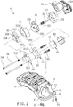
- FIG. 2 is an exploded view in accordance with the first embodiment of the present invention.
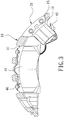
- FIG. 3 is a sectional view in accordance with the first embodiment of the present invention.
- the present invention discloses a brake caliper 100.
- the brake caliper 100 comprises a caliper body 10, a fixing unit 20, a linkage unit 30, a brake lining unit 40, and a drive unit 50.
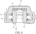
- the caliper body 10 referring to FIG. 4 , has a first accommodation trough 11. A side wall of the first accommodation trough 11 is provided with at least one piston chamber 12. The piston chamber 12 is provided with a piston 13 therein. The caliper body 10 further has a passage 14 communicating with the piston chamber 12. Further, as shown in FIG. 2 , one side of the caliper body 10 has a mounting portion 15. The mounting portion 15 has a second accommodation trough 16, at least one first fixing hole 17, and at least one second fixing hole 18.
- the fixing unit 20, referring to FIG. 2 and FIG. 5 is mounted to the mounting portion 15, and has a first fixing seat 21 and a second fixing seat 22.
- the first fixing seat 21 and the second fixing seat 22 are located at two opposite sides of the second accommodation trough 16, respectively.
- the first fixing seat 21 has a first locking hole 211 corresponding to the first fixing hole 17.
- a first locking member 23 is inserted through the first fixing hole 17 and locked to the first locking hole 211 so as to fix the first fixing seat 21 to the mounting portion 15.
- the second fixing seat 22 has a second locking hole 221 corresponding to the second fixing hole 18.
- a second locking member 24 is inserted through the second fixing hole 18 and locked to the second locking hole 221 so as to fix the second fixing seat 22 to the mounting portion 15.
- first fixing seat 21 is formed with a plurality of first perforations 212
- second fixing seat 22 is formed with a plurality of second perforations 222 corresponding to the first perforations 212.
- the second fixing seat 22 further has a positioning hole 223.
- the linkage unit 30 includes a first linkage seat 31 at an inner side of the first fixing seat 21, a second linkage seat 32 at an inner side of the second fixing seat 22, and a third linkage seat 33 at an outside of the second fixing seat 22.
- the first linkage seat 31 includes a plurality of first guide posts 311 corresponding to the first perforations 212.
- the first guide posts 311 each has a first through hole 312.
- the first linkage seat 31 has a first engaging recess 313.
- the second linkage seat 32 has a plurality of second through holes 321 corresponding to the second perforations 222 and a second guide post 322 corresponding to the positioning hole 223.
- the second guide post 322 has a screw hole 323 therein.
- the second linkage seat 32 has a second engaging recess 324.
- the third linkage seat 33 has a plurality of third through holes 331 corresponding to the second perforations 222 and a through hole 332 corresponding to the positioning hole 223.
- the linkage unit 30 further includes a plurality of linkage pins 34.
- the linkage pins 34 are inserted through the first perforations 212, the second perforations 222, the first through holes 312, the second through holes 321, and the third through holes 331, respectively.
- One end of each of the linkage pins 34 is enlarged to form a head portion 341 which abuts against the corresponding first perforation 212.
- the linkage unit 30 further includes a plurality of elastic members 35.
- the elastic members 35 are sleeved on the linkage pins respectively 34 and located between the first linkage seat 31 and the second linkage seat 32.
- the brake lining unit 40 includes two first brake linings 41 disposed in the first accommodation trough 11 and two second brake linings 42 disposed in the second accommodation trough 16.
- the two second brake linings 42 are fixed to the first linkage seat 31 and the second linkage seat 32, respectively.
- the two second brake linings 42 are fixed to the first engaging recess 313 and the second engaging recess 324, respectively.
- the drive unit 50 includes a positioning seat 51 fixed to an outer outside of the third linkage seat 33.
- the positioning seat 51 has a shaft hole 511 corresponding to the through hole 332.
- the shaft hole 511 is provided with a drive shaft 52.
- One end of the drive shaft 52 is formed with a threaded portion 521.
- the threaded portion 521 is inserted through the through hole 332 and screwed to the screw hole 323.
- the drive unit 50 further includes a motor 53 fixed to an outer side of the positioning seat 51. Another end of the drive shaft 52 is connected to the motor 53.
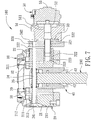
- FIG. 6 is a schematic view showing the use of the first embodiment of the present invention.
- the brake caliper 100 is mounted to a disc 200 of a vehicle.
- the passage 14 of the caliper body 10 is connected with the brake fluid tube of the vehicle.
- the drive unit 50 is connected with the electric parking brake of the vehicle.
- the brake master cylinder of the vehicle feeds the brake fluid into the passage 14 and the brake fluid flows along the passage 14 to push the piston 13, such that the first brake linings 41 are linked to clamp both sides of the disc 200 by a hydraulic means so as to achieve the purpose of foot brake.
- This operation and technical principle are the same as those of the conventional brake caliper and won't be described hereinafter.
- the motor 53 of the drive unit 50 will drive the drive shaft 52 to turn.
- the positioning seat 51 is fixed to the third linkage seat 33, and the threaded portion 521 of the drive shaft 52 is screwed into the screw hole 323 of the second linkage seat 32.
- the threaded portion 521 of the drive shaft 52 is rotated out of the screw hole 323
- the second linkage seat 32 is moved outward relative to third linkage seat 33, so that the second linkage seat 32 urges the corresponding second brake lining 42 to lean against one side of the disc 200.
- the third linkage seat 33 pulls the first linkage seat 31 to move toward the disc 200, so that the first linkage seat 31 urges the other corresponding second brake lining 42 to lean against the other side of the disc 200.
- the two second brake linings 42 are actuated to clamp the two sides of the disc 200 so as to achieve the purpose of electronic hand brake.
- the motor 53 of the drive unit 50 will drive the drive shaft 52 to rotate in the reverse direction, i.e., the drive shaft 52 is rotated into the screw hole 323, while the elastic members 35 provides an elastic force to push the first linkage seat 31 to move outward relative to the second linkage seat 32.
- the third leakage seat 33 is moved by the leakage pins 34 to move toward the disc 200, and the two second linings 42 are moved away from both sides the disc 200 so as to achieve the purpose of releasing electronic hand brake.
- the design of the first guide posts 311 and the second guide post 322 allows the first linkage seat 31 and the second linkage seat 32 to slide more smoothly.
- the brake caliper 100 of the present invention can be used for a vehicle having an electric parking brake, and has the functions of foot brake and electronic hand brake, with the first brake linings 41 for foot brake and with the second brake linings 42 for hand brake, that is, the foot brake and the hand brake are two separate systems that do not interfere with each other, so that there is no problem of noise or vibrations.
- FIG. 8 is a perspective view in accordance with a second embodiment of the present invention.
- FIG. 9 is an exploded view in accordance with the second embodiment of the present invention.
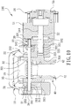
- FIG. 10 is a sectional view in accordance with the second embodiment of the present invention.
- the second embodiment is substantially similar to the first embodiment with the exceptions described hereinafter.
- the first fixing seat 21 and the second fixing seat 22 of the fixing unit 20 are integrally formed with the mounting portion 15 of the caliper body 10, and are located at two opposite sides of the second accommodation trough 16 respectively, thereby facilitating production assembly and improving accuracy of the installation.
Landscapes
- Engineering & Computer Science (AREA)
- General Engineering & Computer Science (AREA)
- Mechanical Engineering (AREA)
- Transportation (AREA)
- Braking Arrangements (AREA)
- Braking Systems And Boosters (AREA)
Abstract
Description
- The present invention relates to a brake caliper of a vehicle, and more particularly to a brake caliper used for an electric parking brake.
- A disc brake system has excellent brake performance, so it is widely used in various vehicles. In general, the main structure of the disc brake system includes a disc and a caliper body disposed at the outer edge of the disc. The caliper body has an engaging trough corresponding to the disc and a pair of brake linings in the engaging trough. The brake linings are located at both sides of the disc, respectively. The caliper body has a plurality of piston chambers corresponding to the brake linings to accommodate pistons, respectively. The caliper body further has a passage in communication with the piston chambers. The passage is connected with the brake fluid tube of the vehicle. When the user pedals the brake pedal of the vehicle, the brake master cylinder of the vehicle feeds the brake fluid into the passage to push the piston, such that the brake linings are linked to clamp both sides of the disc so as to achieve the purpose of foot brake.
- However, in addition to a foot brake function for driving, a vehicle also has a hand brake function for parking. For the caliper to have the hand brake function, the brake linings of the existing caliper are provided with a hook connected with a hand brake line of the vehicle. When the user pulls the hand brake lever, the brake linings are directly pulled by the hand brake line to clamp both sides of the disc so as to achieve the purpose of hand brake. With the development of science and technology, the current hand brake has been developed into an electric parking brake (EPB), so the aforesaid structure cannot be used directly. The foot brake and the hand brake of the aforementioned caliper use the same linings, which accelerates the wear of the brake linings. Besides, when the user releases the foot brake or the hand brake, the brake linings are unable to automatically leave both sides of the disc to cause noise and vibrations. Accordingly, the inventor of the present invention has devoted himself based on his many years of practical experiences to solve these problems.
- The primary object of the present invention is to provide a brake caliper. The brake caliper can be mounted to a vehicle having an electric parking brake, and has the functions of foot brake and electronic hand brake.
- In order to achieve the aforesaid object, the brake caliper of the present invention comprises a caliper body, a fixing unit, a linkage unit, a brake lining unit, and a drive unit. The caliper body has a first accommodation trough. A side wall of the first accommodation trough is provided with at least one piston chamber. The piston chamber is provided with a piston therein. The caliper body further has a passage communicating with the piston chamber. One side of the caliper body has a mounting portion. The mounting portion has a second accommodation trough. The fixing unit is mounted to the mounting portion and has a first fixing seat and a second fixing seat. The first fixing seat and the second fixing seat are located at two opposite sides of the second accommodation trough, respectively. The first fixing seat is formed with a plurality of first perforations. The second fixing seat is formed with a plurality of second perforations corresponding to the first perforations. The second fixing seat further has a positioning hole. The linkage unit includes a first linkage seat at an inner side of the first fixing seat, a second linkage seat at an inner side of the second fixing seat, and a third linkage seat at an outside of the second fixing seat. The first linkage seat has a plurality of first through holes corresponding to the first perforations. The second linkage seat has a plurality of second through holes corresponding to the second perforations and a screw hole corresponding to the positioning hole. The third linkage seat has a plurality of third through holes corresponding to the second perforations and a through hole corresponding to the positioning hole. The linkage unit further includes a plurality of linkage pins. The linkage pins are inserted through the first perforations, the second perforations, the first through holes, the second through holes, and the third through holes, respectively. The linkage unit further includes a plurality of elastic members. The elastic members are fitted on the respective linkage pins and located between the first linkage seat and the second linkage seat. The brake lining unit includes two first brake linings disposed in the first accommodation trough and two second brake linings disposed in the second accommodation trough. The two second brake linings are fixed to the first linkage seat and the second linkage seat, respectively. The drive unit includes a positioning seat fixed to an outer outside of the third linkage seat. The positioning seat has a shaft hole corresponding to the through hole. The shaft hole is provided with a drive shaft. One end of the drive shaft is formed with a threaded portion. The threaded portion is inserted through the through hole and screwed to the screw hole. The drive unit further includes a motor fixed to an outer side of the positioning seat. Another end of the drive shaft is connected to the motor.
- The brake caliper of the present invention can be mounted to a disc of a vehicle. The caliper body is connected with the brake fluid tube of the vehicle. The drive unit is connected with the electric parking brake of the vehicle. When the user pedals the brake pedal of the vehicle, the brake master cylinder of the vehicle pushes the piston of the caliper body by a hydraulic means, such that the first brake linings are pushed to clamp both sides of the disc so as to achieve the purpose of foot brake. When the user activates the electric parking brake, the drive unit will drive the linkage unit to push the two second brake linings to clamp the two sides of the disc so as to achieve the purpose of electronic hand brake.
-
-
FIG. 1 is a perspective view in accordance with a first embodiment of the present invention; -
FIG. 2 is an exploded view in accordance with the first embodiment of the present invention; -
FIG. 3 is a sectional view in accordance with the first embodiment of the present invention; -
FIG. 4 is a sectional view showing the first accommodation trough in accordance with the first embodiment of the present invention; -
FIG. 5 is a sectional view showing the second accommodation trough in accordance with the first embodiment of the present invention; -
FIG. 6 is a schematic view showing the use of the first embodiment of the present invention; -
FIG. 7 is a schematic view showing the operation of the first embodiment of the present invention; -
FIG. 8 is a perspective view in accordance with a second embodiment of the present invention; -
FIG. 9 is an exploded view in accordance with the second embodiment of the present invention; and -
FIG. 10 is a sectional view in accordance with the second embodiment of the present invention. - Embodiments of the present invention will now be described, by way of example only, with reference to the accompanying drawings.
-
FIG. 1 is a perspective view in accordance with a first embodiment of the present invention.FIG. 2 is an exploded view in accordance with the first embodiment of the present invention.FIG. 3 is a sectional view in accordance with the first embodiment of the present invention. The present invention discloses abrake caliper 100. Thebrake caliper 100 comprises acaliper body 10, a fixingunit 20, alinkage unit 30, abrake lining unit 40, and adrive unit 50. - The
caliper body 10, referring toFIG. 4 , has afirst accommodation trough 11. A side wall of thefirst accommodation trough 11 is provided with at least onepiston chamber 12. Thepiston chamber 12 is provided with apiston 13 therein. Thecaliper body 10 further has apassage 14 communicating with thepiston chamber 12. Further, as shown inFIG. 2 , one side of thecaliper body 10 has a mountingportion 15. The mountingportion 15 has asecond accommodation trough 16, at least onefirst fixing hole 17, and at least onesecond fixing hole 18. - The fixing
unit 20, referring toFIG. 2 andFIG. 5 , is mounted to the mountingportion 15, and has a first fixingseat 21 and a second fixingseat 22. The first fixingseat 21 and the second fixingseat 22 are located at two opposite sides of thesecond accommodation trough 16, respectively. In this embodiment, the first fixingseat 21 has afirst locking hole 211 corresponding to the first fixinghole 17. Afirst locking member 23 is inserted through the first fixinghole 17 and locked to thefirst locking hole 211 so as to fix the first fixingseat 21 to the mountingportion 15. The second fixingseat 22 has a second locking hole 221 corresponding to thesecond fixing hole 18. Asecond locking member 24 is inserted through thesecond fixing hole 18 and locked to the second locking hole 221 so as to fix the second fixingseat 22 to the mountingportion 15. In addition, the first fixingseat 21 is formed with a plurality offirst perforations 212, and the second fixingseat 22 is formed with a plurality ofsecond perforations 222 corresponding to thefirst perforations 212. The second fixingseat 22 further has apositioning hole 223. - The
linkage unit 30, referring toFIG. 2 andFIG. 5 , thelinkage unit 30 includes afirst linkage seat 31 at an inner side of the first fixingseat 21, asecond linkage seat 32 at an inner side of the second fixingseat 22, and athird linkage seat 33 at an outside of the second fixingseat 22. Thefirst linkage seat 31 includes a plurality of first guide posts 311 corresponding to thefirst perforations 212. The first guide posts 311 each has a first throughhole 312. Thefirst linkage seat 31 has a firstengaging recess 313. Thesecond linkage seat 32 has a plurality of second throughholes 321 corresponding to thesecond perforations 222 and asecond guide post 322 corresponding to thepositioning hole 223. Thesecond guide post 322 has ascrew hole 323 therein. Thesecond linkage seat 32 has a secondengaging recess 324. Thethird linkage seat 33 has a plurality of third throughholes 331 corresponding to thesecond perforations 222 and a throughhole 332 corresponding to thepositioning hole 223. Thelinkage unit 30 further includes a plurality of linkage pins 34. The linkage pins 34 are inserted through thefirst perforations 212, thesecond perforations 222, the first throughholes 312, the second throughholes 321, and the third throughholes 331, respectively. One end of each of the linkage pins 34 is enlarged to form ahead portion 341 which abuts against the correspondingfirst perforation 212. Another end of each of the linkage pins 334 is formed with a lockingportion 342. The lockingportion 342 is locked to the corresponding third throughhole 331. Thelinkage unit 30 further includes a plurality ofelastic members 35. Theelastic members 35 are sleeved on the linkage pins respectively 34 and located between thefirst linkage seat 31 and thesecond linkage seat 32. - The
brake lining unit 40, referring toFIG. 3 to FIG. 5 , includes twofirst brake linings 41 disposed in thefirst accommodation trough 11 and twosecond brake linings 42 disposed in thesecond accommodation trough 16. The twosecond brake linings 42 are fixed to thefirst linkage seat 31 and thesecond linkage seat 32, respectively. In this embodiment, the twosecond brake linings 42 are fixed to the firstengaging recess 313 and the secondengaging recess 324, respectively. - The
drive unit 50, referringFIG. 2 andFIG. 5 , includes apositioning seat 51 fixed to an outer outside of thethird linkage seat 33. The positioningseat 51 has ashaft hole 511 corresponding to the throughhole 332. Theshaft hole 511 is provided with adrive shaft 52. One end of thedrive shaft 52 is formed with a threadedportion 521. The threadedportion 521 is inserted through the throughhole 332 and screwed to thescrew hole 323. Thedrive unit 50 further includes amotor 53 fixed to an outer side of thepositioning seat 51. Another end of thedrive shaft 52 is connected to themotor 53. -
FIG. 6 is a schematic view showing the use of the first embodiment of the present invention. Thebrake caliper 100 is mounted to adisc 200 of a vehicle. Thepassage 14 of thecaliper body 10 is connected with the brake fluid tube of the vehicle. Thedrive unit 50 is connected with the electric parking brake of the vehicle. When the user pedals the brake pedal of the vehicle, as shown inFIG. 4 , the brake master cylinder of the vehicle feeds the brake fluid into thepassage 14 and the brake fluid flows along thepassage 14 to push thepiston 13, such that thefirst brake linings 41 are linked to clamp both sides of thedisc 200 by a hydraulic means so as to achieve the purpose of foot brake. This operation and technical principle are the same as those of the conventional brake caliper and won't be described hereinafter. - Referring to
FIG. 7 , when the user activates the electric parking brake, themotor 53 of thedrive unit 50 will drive thedrive shaft 52 to turn. The positioningseat 51 is fixed to thethird linkage seat 33, and the threadedportion 521 of thedrive shaft 52 is screwed into thescrew hole 323 of thesecond linkage seat 32. When the threadedportion 521 of thedrive shaft 52 is rotated out of thescrew hole 323, thesecond linkage seat 32 is moved outward relative tothird linkage seat 33, so that thesecond linkage seat 32 urges the correspondingsecond brake lining 42 to lean against one side of thedisc 200. Through the linkage pins 34, thethird linkage seat 33 pulls thefirst linkage seat 31 to move toward thedisc 200, so that thefirst linkage seat 31 urges the other correspondingsecond brake lining 42 to lean against the other side of thedisc 200. The twosecond brake linings 42 are actuated to clamp the two sides of thedisc 200 so as to achieve the purpose of electronic hand brake. - When the user releases the electric parking brake, the
motor 53 of thedrive unit 50 will drive thedrive shaft 52 to rotate in the reverse direction, i.e., thedrive shaft 52 is rotated into thescrew hole 323, while theelastic members 35 provides an elastic force to push thefirst linkage seat 31 to move outward relative to thesecond linkage seat 32. Thethird leakage seat 33 is moved by the leakage pins 34 to move toward thedisc 200, and the twosecond linings 42 are moved away from both sides thedisc 200 so as to achieve the purpose of releasing electronic hand brake. The design of the first guide posts 311 and thesecond guide post 322 allows thefirst linkage seat 31 and thesecond linkage seat 32 to slide more smoothly. - Thereby, the
brake caliper 100 of the present invention can be used for a vehicle having an electric parking brake, and has the functions of foot brake and electronic hand brake, with thefirst brake linings 41 for foot brake and with thesecond brake linings 42 for hand brake, that is, the foot brake and the hand brake are two separate systems that do not interfere with each other, so that there is no problem of noise or vibrations. -
FIG. 8 is a perspective view in accordance with a second embodiment of the present invention.FIG. 9 is an exploded view in accordance with the second embodiment of the present invention.FIG. 10 is a sectional view in accordance with the second embodiment of the present invention. The second embodiment is substantially similar to the first embodiment with the exceptions described hereinafter. The first fixingseat 21 and the second fixingseat 22 of the fixingunit 20 are integrally formed with the mountingportion 15 of thecaliper body 10, and are located at two opposite sides of thesecond accommodation trough 16 respectively, thereby facilitating production assembly and improving accuracy of the installation. - Although particular embodiments of the present invention have been described in detail for purposes of illustration, various modifications and enhancements may be made without departing from the spirit and scope of the present invention. Accordingly, the present invention is not to be limited except as by the appended claims.
Claims (7)
- A brake caliper, comprising:a caliper body, having a first accommodation trough, a side wall of the first accommodation trough being provided with at least one piston chamber, the piston chamber being provided with a piston therein, the caliper body further having a passage communicating with the piston chamber, one side of the caliper body having a mounting portion, the mounting portion having a second accommodation trough;a fixing unit, mounted to the mounting portion and having a first fixing seat and a second fixing seat, the first fixing seat and the second fixing seat being located at two opposite sides of the second accommodation trough respectively; the first fixing seat being formed with a plurality of first perforations, the second fixing seat being formed with a plurality of second perforations corresponding to the first perforations, the second fixing seat further having a positioning hole;a linkage unit, including a first linkage seat at an inner side of the first fixing seat, a second linkage seat at an inner side of the second fixing seat, and a third linkage seat at an outside of the second fixing seat; the first linkage seat having a plurality of first through holes corresponding to the first perforations; the second linkage seat having a plurality of second through holes corresponding to the second perforations and a screw hole corresponding to the positioning hole; the third linkage seat having a plurality of third through holes corresponding to the second perforations and a through hole corresponding to the positioning hole; the linkage unit further including a plurality of linkage pins, the linkage pins being inserted through the first perforations, the second perforations, the first through holes, the second through holes, and the third through holes respectively; the linkage unit further including a plurality of elastic members, the elastic members being fitted on the respective linkage pins and located between the first linkage seat and the second linkage seat;a brake lining unit, including two first brake linings disposed in the first accommodation trough and two second brake linings disposed in the second accommodation trough; the two second brake linings being fixed to the first linkage seat and the second linkage seat, respectively; anda drive unit, including a positioning seat fixed to an outer outside of the third linkage seat, the positioning seat having a shaft hole corresponding to the through hole, the shaft hole being provided with a drive shaft, one end of the drive shaft being formed with a threaded portion, the threaded portion being inserted through the through hole and screwed to the screw hole, the drive unit further including a motor fixed to an outer side of the positioning seat, another end of the drive shaft being connected to the motor.
- The brake caliper as claimed in claim 1, wherein the mounting portion has at least one first fixing hole and at least one second fixing hole, the first fixing seat has a first locking hole corresponding to the first fixing hole, a first locking member is inserted through the first fixing hole and locked to the first locking hole so as to fix the first fixing seat to the mounting portion, the second fixing seat has a second locking hole corresponding to the second fixing hole, and a second locking member is inserted through the second fixing hole and locked to the second locking hole so as to fix the second fixing seat to the mounting portion.
- The brake caliper as claimed in claim 1, wherein the first fixing seat and the second fixing seat of the fixing unit are integrally formed with the mounting portion of the caliper body and located at the two opposite sides of the second accommodation trough, respectively.
- The brake caliper as claimed in claim 1, wherein the first linkage seat includes a plurality of first guide posts corresponding to the first perforations, and the first guide posts are formed with the first through holes.
- The brake caliper as claimed in claim 1, wherein the second linkage seat has a second guide post corresponding to the through hole, and the second guide post is formed with the screw hole.
- The brake caliper as claimed in claim 1, wherein one end of each of the linkage pins is enlarged to form a head portion which abuts against a corresponding one of the first perforations, another end of each of the linkage pins is formed with a locking portion, and the locking portion is locked to a corresponding one of the third through holes.
- The brake caliper as claimed in claim 1, wherein the first linkage seat has a first engaging recess, the second linkage seat has a second engaging recess, and the two second brake linings are fixed to the first engaging recess and the second engaging recess, respectively.
Applications Claiming Priority (1)
| Application Number | Priority Date | Filing Date | Title |
|---|---|---|---|
| TW105211250U TWM530777U (en) | 2016-07-26 | 2016-07-26 | Electronic brake calipers |
Publications (2)
| Publication Number | Publication Date |
|---|---|
| EP3276199A1 true EP3276199A1 (en) | 2018-01-31 |
| EP3276199B1 EP3276199B1 (en) | 2019-05-15 |
Family
ID=57849779
Family Applications (1)
| Application Number | Title | Priority Date | Filing Date |
|---|---|---|---|
| EP17000877.5A Not-in-force EP3276199B1 (en) | 2016-07-26 | 2017-05-22 | Brake caliper |
Country Status (5)
| Country | Link |
|---|---|
| US (1) | US10066686B2 (en) |
| EP (1) | EP3276199B1 (en) |
| JP (1) | JP3211799U (en) |
| CN (1) | CN206816708U (en) |
| TW (1) | TWM530777U (en) |
Cited By (1)
| Publication number | Priority date | Publication date | Assignee | Title |
|---|---|---|---|---|
| US12227152B2 (en) * | 2021-09-15 | 2025-02-18 | Jieh Jia Enterprise Co., Ltd. | Brake caliper |
Families Citing this family (18)
| Publication number | Priority date | Publication date | Assignee | Title |
|---|---|---|---|---|
| USD335935S (en) * | 1991-03-25 | 1993-05-25 | Victoria Rouail | Support bracket for a household appliance such as a hair dryer |
| TWI616603B (en) * | 2016-05-20 | 2018-03-01 | Tw Racing Parts Inc | Electronic parking calipers |
| USD854985S1 (en) * | 2016-12-19 | 2019-07-30 | Freni Brembo S.P.A. | Disc brake caliper |
| TWD186793S (en) * | 2016-12-23 | 2017-11-21 | 捷加企業股份有限公司 | Part of the electronic brake caliper |
| JP1603869S (en) * | 2017-04-13 | 2018-05-14 | ||
| USD864062S1 (en) * | 2017-04-13 | 2019-10-22 | Freni Brembo S.P.A. | Disc brake caliper |
| DE102017116323A1 (en) * | 2017-07-19 | 2019-01-24 | Lucas Automotive Gmbh | Disc brake, disc brake system and parking brake system |
| DE102018210236A1 (en) * | 2018-06-22 | 2019-12-24 | Robert Bosch Gmbh | wheel brake |
| CN108825681B (en) * | 2018-07-02 | 2019-12-24 | 廖志贤 | Reaction type caliper device |
| USD894065S1 (en) * | 2018-12-19 | 2020-08-25 | Akebono Brake Industry Co., Ltd. | Multi-piston caliper |
| US11105385B2 (en) * | 2019-02-11 | 2021-08-31 | ZF Active Safety US Inc. | Twin piston caliper with electric parking brake and method of operating such a twin piston caliper with electric parking brake |
| JP7253404B2 (en) * | 2019-02-25 | 2023-04-06 | 日立Astemo株式会社 | vehicle disc brake |
| KR102718510B1 (en) * | 2019-07-16 | 2024-10-22 | 현대모비스 주식회사 | Parking brake apparatus for vehicle |
| CN110762137A (en) * | 2019-10-22 | 2020-02-07 | 精诚工科汽车系统有限公司 | Brake caliper device and vehicle with same |
| USD938871S1 (en) * | 2019-11-01 | 2021-12-21 | Mando Corporation | Disc brake caliper for vehicle |
| CN111267023B (en) * | 2020-03-04 | 2025-05-27 | 青岛新松机器人自动化有限公司 | Open positioning jaw assembly and single-drive bidirectional open positioning device |
| US11313425B2 (en) * | 2020-07-13 | 2022-04-26 | Kema Enterprise Co., Ltd. | Motor transmission unit for electronic parking brake device |
| CN117685314A (en) * | 2022-09-05 | 2024-03-12 | 芜湖伯特利汽车安全系统股份有限公司 | brake caliper |
Citations (3)
| Publication number | Priority date | Publication date | Assignee | Title |
|---|---|---|---|---|
| EP1167804A1 (en) * | 2000-06-22 | 2002-01-02 | Freni Brembo S.p.A. | A caliper body for a fixed caliper disc brake |
| US20150001010A1 (en) * | 2013-06-26 | 2015-01-01 | Chih-Hsien Liao | Electric parking caliper |
| US20150021125A1 (en) * | 2012-02-16 | 2015-01-22 | Freni Brembo S.P.A. | Caliper assembly for service and parking disc brake |
Family Cites Families (7)
| Publication number | Priority date | Publication date | Assignee | Title |
|---|---|---|---|---|
| US2983338A (en) * | 1958-08-25 | 1961-05-09 | Ford Motor Co | Spot disc brake |
| CH394834A (en) * | 1962-12-07 | 1965-06-30 | Campagnolo Tullio | Disc brake for motor vehicles in general with hydraulic and mechanical actuation |
| US3321049A (en) * | 1965-05-12 | 1967-05-23 | Kelsey Hayes Co | Mechanical floating head brake |
| JP3901329B2 (en) * | 1998-02-10 | 2007-04-04 | 日清紡績株式会社 | Disc brake device |
| DE602005014020D1 (en) * | 2005-10-05 | 2009-05-28 | Freni Brembo Spa | DISC BRAKING SYSTEM FOR A VEHICLE COMBINING OPERATOR AND PARKING BRAKE |
| ITMI20120233A1 (en) * | 2012-02-16 | 2013-08-17 | Freni Brembo Spa | PARKING CLAMP ASSEMBLY |
| US9777782B2 (en) * | 2013-06-19 | 2017-10-03 | Kelsey-Hayes Company | Shared anchor bracket for a disc brake assembly having separate service and parking brake assemblies |
-
2016
- 2016-07-26 TW TW105211250U patent/TWM530777U/en not_active IP Right Cessation
-
2017
- 2017-05-11 US US15/593,191 patent/US10066686B2/en not_active Expired - Fee Related
- 2017-05-15 CN CN201720533113.7U patent/CN206816708U/en not_active Expired - Fee Related
- 2017-05-22 EP EP17000877.5A patent/EP3276199B1/en not_active Not-in-force
- 2017-05-25 JP JP2017002336U patent/JP3211799U/en not_active Expired - Fee Related
Patent Citations (3)
| Publication number | Priority date | Publication date | Assignee | Title |
|---|---|---|---|---|
| EP1167804A1 (en) * | 2000-06-22 | 2002-01-02 | Freni Brembo S.p.A. | A caliper body for a fixed caliper disc brake |
| US20150021125A1 (en) * | 2012-02-16 | 2015-01-22 | Freni Brembo S.P.A. | Caliper assembly for service and parking disc brake |
| US20150001010A1 (en) * | 2013-06-26 | 2015-01-01 | Chih-Hsien Liao | Electric parking caliper |
Cited By (1)
| Publication number | Priority date | Publication date | Assignee | Title |
|---|---|---|---|---|
| US12227152B2 (en) * | 2021-09-15 | 2025-02-18 | Jieh Jia Enterprise Co., Ltd. | Brake caliper |
Also Published As
| Publication number | Publication date |
|---|---|
| CN206816708U (en) | 2017-12-29 |
| US20180031060A1 (en) | 2018-02-01 |
| EP3276199B1 (en) | 2019-05-15 |
| US10066686B2 (en) | 2018-09-04 |
| TWM530777U (en) | 2016-10-21 |
| JP3211799U (en) | 2017-08-03 |
Similar Documents
| Publication | Publication Date | Title |
|---|---|---|
| US10066686B2 (en) | Brake caliper | |
| US10919510B2 (en) | Integrated hydraulic module of an electrohydraulic servo brake | |
| EP1847430A1 (en) | Hydraulic modulator for brake device | |
| US20090107777A1 (en) | Parking brake device of disk brake | |
| US20150001010A1 (en) | Electric parking caliper | |
| US9272695B2 (en) | Electric parking brake | |
| JP7054318B2 (en) | Hydraulic pressure control unit for saddle-type vehicle brake system and saddle-type vehicle brake system | |
| DE102018125566A1 (en) | BRAKING DEVICE AND BRAKING SYSTEM | |
| RU2402410C2 (en) | Rotary cutting tool | |
| US6341673B1 (en) | Actuator for a hydraulic brake system of bicycles | |
| EP4151878A1 (en) | Brake caliper | |
| KR101938107B1 (en) | Monoblock brake caliper with function of braking for parking | |
| EP1729028A4 (en) | PARKING BRAKE DEVICE | |
| WO2009124494A1 (en) | An antilock brake structure | |
| JP2009068686A (en) | Mounting dimension adjustment member | |
| US9963193B2 (en) | Cable positioning structure for hydraulic brake of bicycle | |
| CN110762137A (en) | Brake caliper device and vehicle with same | |
| US6607252B2 (en) | Anti-vibration brake system | |
| CN111692225B (en) | Clutch device and retainer thereof | |
| US10914353B2 (en) | Mechanical disc brake structure | |
| US20150143991A1 (en) | Master cylinder with recessed piston-rod interface | |
| CN104863999A (en) | Electronic parking caliper | |
| CN221366946U (en) | Integrated brake structure | |
| TW201531632A (en) | Electronic parking caliper | |
| AU2015213295B2 (en) | Electric parking brake |
Legal Events
| Date | Code | Title | Description |
|---|---|---|---|
| PUAI | Public reference made under article 153(3) epc to a published international application that has entered the european phase |
Free format text: ORIGINAL CODE: 0009012 |
|
| STAA | Information on the status of an ep patent application or granted ep patent |
Free format text: STATUS: THE APPLICATION HAS BEEN PUBLISHED |
|
| AK | Designated contracting states |
Kind code of ref document: A1 Designated state(s): AL AT BE BG CH CY CZ DE DK EE ES FI FR GB GR HR HU IE IS IT LI LT LU LV MC MK MT NL NO PL PT RO RS SE SI SK SM TR |
|
| AX | Request for extension of the european patent |
Extension state: BA ME |
|
| STAA | Information on the status of an ep patent application or granted ep patent |
Free format text: STATUS: REQUEST FOR EXAMINATION WAS MADE |
|
| 17P | Request for examination filed |
Effective date: 20180724 |
|
| RBV | Designated contracting states (corrected) |
Designated state(s): AL AT BE BG CH CY CZ DE DK EE ES FI FR GB GR HR HU IE IS IT LI LT LU LV MC MK MT NL NO PL PT RO RS SE SI SK SM TR |
|
| GRAP | Despatch of communication of intention to grant a patent |
Free format text: ORIGINAL CODE: EPIDOSNIGR1 |
|
| STAA | Information on the status of an ep patent application or granted ep patent |
Free format text: STATUS: GRANT OF PATENT IS INTENDED |
|
| INTG | Intention to grant announced |
Effective date: 20190103 |
|
| GRAS | Grant fee paid |
Free format text: ORIGINAL CODE: EPIDOSNIGR3 |
|
| GRAA | (expected) grant |
Free format text: ORIGINAL CODE: 0009210 |
|
| STAA | Information on the status of an ep patent application or granted ep patent |
Free format text: STATUS: THE PATENT HAS BEEN GRANTED |
|
| AK | Designated contracting states |
Kind code of ref document: B1 Designated state(s): AL AT BE BG CH CY CZ DE DK EE ES FI FR GB GR HR HU IE IS IT LI LT LU LV MC MK MT NL NO PL PT RO RS SE SI SK SM TR |
|
| REG | Reference to a national code |
Ref country code: CH Ref legal event code: EP |
|
| REG | Reference to a national code |
Ref country code: DE Ref legal event code: R096 Ref document number: 602017003797 Country of ref document: DE |
|
| REG | Reference to a national code |
Ref country code: IE Ref legal event code: FG4D |
|
| REG | Reference to a national code |
Ref country code: NL Ref legal event code: MP Effective date: 20190515 |
|
| REG | Reference to a national code |
Ref country code: LT Ref legal event code: MG4D |
|
| PG25 | Lapsed in a contracting state [announced via postgrant information from national office to epo] |
Ref country code: AL Free format text: LAPSE BECAUSE OF FAILURE TO SUBMIT A TRANSLATION OF THE DESCRIPTION OR TO PAY THE FEE WITHIN THE PRESCRIBED TIME-LIMIT Effective date: 20190515 Ref country code: PT Free format text: LAPSE BECAUSE OF FAILURE TO SUBMIT A TRANSLATION OF THE DESCRIPTION OR TO PAY THE FEE WITHIN THE PRESCRIBED TIME-LIMIT Effective date: 20190915 Ref country code: NL Free format text: LAPSE BECAUSE OF FAILURE TO SUBMIT A TRANSLATION OF THE DESCRIPTION OR TO PAY THE FEE WITHIN THE PRESCRIBED TIME-LIMIT Effective date: 20190515 Ref country code: LT Free format text: LAPSE BECAUSE OF FAILURE TO SUBMIT A TRANSLATION OF THE DESCRIPTION OR TO PAY THE FEE WITHIN THE PRESCRIBED TIME-LIMIT Effective date: 20190515 Ref country code: HR Free format text: LAPSE BECAUSE OF FAILURE TO SUBMIT A TRANSLATION OF THE DESCRIPTION OR TO PAY THE FEE WITHIN THE PRESCRIBED TIME-LIMIT Effective date: 20190515 Ref country code: NO Free format text: LAPSE BECAUSE OF FAILURE TO SUBMIT A TRANSLATION OF THE DESCRIPTION OR TO PAY THE FEE WITHIN THE PRESCRIBED TIME-LIMIT Effective date: 20190815 Ref country code: SE Free format text: LAPSE BECAUSE OF FAILURE TO SUBMIT A TRANSLATION OF THE DESCRIPTION OR TO PAY THE FEE WITHIN THE PRESCRIBED TIME-LIMIT Effective date: 20190515 Ref country code: FI Free format text: LAPSE BECAUSE OF FAILURE TO SUBMIT A TRANSLATION OF THE DESCRIPTION OR TO PAY THE FEE WITHIN THE PRESCRIBED TIME-LIMIT Effective date: 20190515 |
|
| PG25 | Lapsed in a contracting state [announced via postgrant information from national office to epo] |
Ref country code: RS Free format text: LAPSE BECAUSE OF FAILURE TO SUBMIT A TRANSLATION OF THE DESCRIPTION OR TO PAY THE FEE WITHIN THE PRESCRIBED TIME-LIMIT Effective date: 20190515 Ref country code: GR Free format text: LAPSE BECAUSE OF FAILURE TO SUBMIT A TRANSLATION OF THE DESCRIPTION OR TO PAY THE FEE WITHIN THE PRESCRIBED TIME-LIMIT Effective date: 20190816 Ref country code: LV Free format text: LAPSE BECAUSE OF FAILURE TO SUBMIT A TRANSLATION OF THE DESCRIPTION OR TO PAY THE FEE WITHIN THE PRESCRIBED TIME-LIMIT Effective date: 20190515 Ref country code: BG Free format text: LAPSE BECAUSE OF FAILURE TO SUBMIT A TRANSLATION OF THE DESCRIPTION OR TO PAY THE FEE WITHIN THE PRESCRIBED TIME-LIMIT Effective date: 20190815 |
|
| REG | Reference to a national code |
Ref country code: AT Ref legal event code: MK05 Ref document number: 1133797 Country of ref document: AT Kind code of ref document: T Effective date: 20190515 |
|
| PG25 | Lapsed in a contracting state [announced via postgrant information from national office to epo] |
Ref country code: SK Free format text: LAPSE BECAUSE OF FAILURE TO SUBMIT A TRANSLATION OF THE DESCRIPTION OR TO PAY THE FEE WITHIN THE PRESCRIBED TIME-LIMIT Effective date: 20190515 Ref country code: CZ Free format text: LAPSE BECAUSE OF FAILURE TO SUBMIT A TRANSLATION OF THE DESCRIPTION OR TO PAY THE FEE WITHIN THE PRESCRIBED TIME-LIMIT Effective date: 20190515 Ref country code: DK Free format text: LAPSE BECAUSE OF FAILURE TO SUBMIT A TRANSLATION OF THE DESCRIPTION OR TO PAY THE FEE WITHIN THE PRESCRIBED TIME-LIMIT Effective date: 20190515 Ref country code: AT Free format text: LAPSE BECAUSE OF FAILURE TO SUBMIT A TRANSLATION OF THE DESCRIPTION OR TO PAY THE FEE WITHIN THE PRESCRIBED TIME-LIMIT Effective date: 20190515 Ref country code: EE Free format text: LAPSE BECAUSE OF FAILURE TO SUBMIT A TRANSLATION OF THE DESCRIPTION OR TO PAY THE FEE WITHIN THE PRESCRIBED TIME-LIMIT Effective date: 20190515 |
|
| REG | Reference to a national code |
Ref country code: BE Ref legal event code: MM Effective date: 20190531 |
|
| REG | Reference to a national code |
Ref country code: DE Ref legal event code: R097 Ref document number: 602017003797 Country of ref document: DE |
|
| PG25 | Lapsed in a contracting state [announced via postgrant information from national office to epo] |
Ref country code: MC Free format text: LAPSE BECAUSE OF FAILURE TO SUBMIT A TRANSLATION OF THE DESCRIPTION OR TO PAY THE FEE WITHIN THE PRESCRIBED TIME-LIMIT Effective date: 20190515 Ref country code: SM Free format text: LAPSE BECAUSE OF FAILURE TO SUBMIT A TRANSLATION OF THE DESCRIPTION OR TO PAY THE FEE WITHIN THE PRESCRIBED TIME-LIMIT Effective date: 20190515 Ref country code: IT Free format text: LAPSE BECAUSE OF FAILURE TO SUBMIT A TRANSLATION OF THE DESCRIPTION OR TO PAY THE FEE WITHIN THE PRESCRIBED TIME-LIMIT Effective date: 20190515 Ref country code: LU Free format text: LAPSE BECAUSE OF NON-PAYMENT OF DUE FEES Effective date: 20190522 |
|
| PLBE | No opposition filed within time limit |
Free format text: ORIGINAL CODE: 0009261 |
|
| STAA | Information on the status of an ep patent application or granted ep patent |
Free format text: STATUS: NO OPPOSITION FILED WITHIN TIME LIMIT |
|
| PG25 | Lapsed in a contracting state [announced via postgrant information from national office to epo] |
Ref country code: TR Free format text: LAPSE BECAUSE OF FAILURE TO SUBMIT A TRANSLATION OF THE DESCRIPTION OR TO PAY THE FEE WITHIN THE PRESCRIBED TIME-LIMIT Effective date: 20190515 |
|
| 26N | No opposition filed |
Effective date: 20200218 |
|
| PG25 | Lapsed in a contracting state [announced via postgrant information from national office to epo] |
Ref country code: IE Free format text: LAPSE BECAUSE OF NON-PAYMENT OF DUE FEES Effective date: 20190522 Ref country code: PL Free format text: LAPSE BECAUSE OF FAILURE TO SUBMIT A TRANSLATION OF THE DESCRIPTION OR TO PAY THE FEE WITHIN THE PRESCRIBED TIME-LIMIT Effective date: 20190515 |
|
| PG25 | Lapsed in a contracting state [announced via postgrant information from national office to epo] |
Ref country code: BE Free format text: LAPSE BECAUSE OF NON-PAYMENT OF DUE FEES Effective date: 20190531 Ref country code: SI Free format text: LAPSE BECAUSE OF FAILURE TO SUBMIT A TRANSLATION OF THE DESCRIPTION OR TO PAY THE FEE WITHIN THE PRESCRIBED TIME-LIMIT Effective date: 20190515 |
|
| PGFP | Annual fee paid to national office [announced via postgrant information from national office to epo] |
Ref country code: FR Payment date: 20200519 Year of fee payment: 4 |
|
| PG25 | Lapsed in a contracting state [announced via postgrant information from national office to epo] |
Ref country code: ES Free format text: LAPSE BECAUSE OF FAILURE TO SUBMIT A TRANSLATION OF THE DESCRIPTION OR TO PAY THE FEE WITHIN THE PRESCRIBED TIME-LIMIT Effective date: 20190515 |
|
| PGFP | Annual fee paid to national office [announced via postgrant information from national office to epo] |
Ref country code: DE Payment date: 20200730 Year of fee payment: 4 |
|
| PG25 | Lapsed in a contracting state [announced via postgrant information from national office to epo] |
Ref country code: LI Free format text: LAPSE BECAUSE OF NON-PAYMENT OF DUE FEES Effective date: 20200531 Ref country code: CH Free format text: LAPSE BECAUSE OF NON-PAYMENT OF DUE FEES Effective date: 20200531 |
|
| PG25 | Lapsed in a contracting state [announced via postgrant information from national office to epo] |
Ref country code: RO Free format text: LAPSE BECAUSE OF FAILURE TO SUBMIT A TRANSLATION OF THE DESCRIPTION OR TO PAY THE FEE WITHIN THE PRESCRIBED TIME-LIMIT Effective date: 20190515 |
|
| PG25 | Lapsed in a contracting state [announced via postgrant information from national office to epo] |
Ref country code: CY Free format text: LAPSE BECAUSE OF FAILURE TO SUBMIT A TRANSLATION OF THE DESCRIPTION OR TO PAY THE FEE WITHIN THE PRESCRIBED TIME-LIMIT Effective date: 20190515 |
|
| PG25 | Lapsed in a contracting state [announced via postgrant information from national office to epo] |
Ref country code: IS Free format text: LAPSE BECAUSE OF FAILURE TO SUBMIT A TRANSLATION OF THE DESCRIPTION OR TO PAY THE FEE WITHIN THE PRESCRIBED TIME-LIMIT Effective date: 20190915 |
|
| PG25 | Lapsed in a contracting state [announced via postgrant information from national office to epo] |
Ref country code: HU Free format text: LAPSE BECAUSE OF FAILURE TO SUBMIT A TRANSLATION OF THE DESCRIPTION OR TO PAY THE FEE WITHIN THE PRESCRIBED TIME-LIMIT; INVALID AB INITIO Effective date: 20170522 Ref country code: MT Free format text: LAPSE BECAUSE OF FAILURE TO SUBMIT A TRANSLATION OF THE DESCRIPTION OR TO PAY THE FEE WITHIN THE PRESCRIBED TIME-LIMIT Effective date: 20190515 |
|
| REG | Reference to a national code |
Ref country code: DE Ref legal event code: R119 Ref document number: 602017003797 Country of ref document: DE |
|
| GBPC | Gb: european patent ceased through non-payment of renewal fee |
Effective date: 20210522 |
|
| PG25 | Lapsed in a contracting state [announced via postgrant information from national office to epo] |
Ref country code: GB Free format text: LAPSE BECAUSE OF NON-PAYMENT OF DUE FEES Effective date: 20210522 Ref country code: DE Free format text: LAPSE BECAUSE OF NON-PAYMENT OF DUE FEES Effective date: 20211201 |
|
| PG25 | Lapsed in a contracting state [announced via postgrant information from national office to epo] |
Ref country code: FR Free format text: LAPSE BECAUSE OF NON-PAYMENT OF DUE FEES Effective date: 20210531 |
|
| PG25 | Lapsed in a contracting state [announced via postgrant information from national office to epo] |
Ref country code: MK Free format text: LAPSE BECAUSE OF FAILURE TO SUBMIT A TRANSLATION OF THE DESCRIPTION OR TO PAY THE FEE WITHIN THE PRESCRIBED TIME-LIMIT Effective date: 20190515 |