EP3275780A1 - Thin-skin side stay beams and landing gear assemblies - Google Patents
Thin-skin side stay beams and landing gear assemblies Download PDFInfo
- Publication number
- EP3275780A1 EP3275780A1 EP17174624.1A EP17174624A EP3275780A1 EP 3275780 A1 EP3275780 A1 EP 3275780A1 EP 17174624 A EP17174624 A EP 17174624A EP 3275780 A1 EP3275780 A1 EP 3275780A1
- Authority
- EP
- European Patent Office
- Prior art keywords
- thin
- skin
- internal wall
- thin skin
- arm
- Prior art date
- Legal status (The legal status is an assumption and is not a legal conclusion. Google has not performed a legal analysis and makes no representation as to the accuracy of the status listed.)
- Granted
Links
Images




Classifications
-
- B—PERFORMING OPERATIONS; TRANSPORTING
- B64—AIRCRAFT; AVIATION; COSMONAUTICS
- B64C—AEROPLANES; HELICOPTERS
- B64C25/00—Alighting gear
- B64C25/02—Undercarriages
- B64C25/08—Undercarriages non-fixed, e.g. jettisonable
- B64C25/10—Undercarriages non-fixed, e.g. jettisonable retractable, foldable, or the like
- B64C25/12—Undercarriages non-fixed, e.g. jettisonable retractable, foldable, or the like sideways
-
- B—PERFORMING OPERATIONS; TRANSPORTING
- B22—CASTING; POWDER METALLURGY
- B22F—WORKING METALLIC POWDER; MANUFACTURE OF ARTICLES FROM METALLIC POWDER; MAKING METALLIC POWDER; APPARATUS OR DEVICES SPECIALLY ADAPTED FOR METALLIC POWDER
- B22F10/00—Additive manufacturing of workpieces or articles from metallic powder
- B22F10/20—Direct sintering or melting
-
- B—PERFORMING OPERATIONS; TRANSPORTING
- B22—CASTING; POWDER METALLURGY
- B22F—WORKING METALLIC POWDER; MANUFACTURE OF ARTICLES FROM METALLIC POWDER; MAKING METALLIC POWDER; APPARATUS OR DEVICES SPECIALLY ADAPTED FOR METALLIC POWDER
- B22F3/00—Manufacture of workpieces or articles from metallic powder characterised by the manner of compacting or sintering; Apparatus specially adapted therefor ; Presses and furnaces
- B22F3/10—Sintering only
- B22F3/1017—Multiple heating or additional steps
-
- B—PERFORMING OPERATIONS; TRANSPORTING
- B22—CASTING; POWDER METALLURGY
- B22F—WORKING METALLIC POWDER; MANUFACTURE OF ARTICLES FROM METALLIC POWDER; MAKING METALLIC POWDER; APPARATUS OR DEVICES SPECIALLY ADAPTED FOR METALLIC POWDER
- B22F5/00—Manufacture of workpieces or articles from metallic powder characterised by the special shape of the product
- B22F5/10—Manufacture of workpieces or articles from metallic powder characterised by the special shape of the product of articles with cavities or holes, not otherwise provided for in the preceding subgroups
- B22F5/106—Tube or ring forms
-
- B—PERFORMING OPERATIONS; TRANSPORTING
- B23—MACHINE TOOLS; METAL-WORKING NOT OTHERWISE PROVIDED FOR
- B23K—SOLDERING OR UNSOLDERING; WELDING; CLADDING OR PLATING BY SOLDERING OR WELDING; CUTTING BY APPLYING HEAT LOCALLY, e.g. FLAME CUTTING; WORKING BY LASER BEAM
- B23K15/00—Electron-beam welding or cutting
- B23K15/0046—Welding
- B23K15/0086—Welding welding for purposes other than joining, e.g. build-up welding
-
- B—PERFORMING OPERATIONS; TRANSPORTING
- B23—MACHINE TOOLS; METAL-WORKING NOT OTHERWISE PROVIDED FOR
- B23K—SOLDERING OR UNSOLDERING; WELDING; CLADDING OR PLATING BY SOLDERING OR WELDING; CUTTING BY APPLYING HEAT LOCALLY, e.g. FLAME CUTTING; WORKING BY LASER BEAM
- B23K26/00—Working by laser beam, e.g. welding, cutting or boring
- B23K26/34—Laser welding for purposes other than joining
- B23K26/342—Build-up welding
-
- B—PERFORMING OPERATIONS; TRANSPORTING
- B23—MACHINE TOOLS; METAL-WORKING NOT OTHERWISE PROVIDED FOR
- B23K—SOLDERING OR UNSOLDERING; WELDING; CLADDING OR PLATING BY SOLDERING OR WELDING; CUTTING BY APPLYING HEAT LOCALLY, e.g. FLAME CUTTING; WORKING BY LASER BEAM
- B23K9/00—Arc welding or cutting
- B23K9/04—Welding for other purposes than joining, e.g. built-up welding
- B23K9/044—Built-up welding on three-dimensional surfaces
-
- B—PERFORMING OPERATIONS; TRANSPORTING
- B33—ADDITIVE MANUFACTURING TECHNOLOGY
- B33Y—ADDITIVE MANUFACTURING, i.e. MANUFACTURING OF THREE-DIMENSIONAL [3D] OBJECTS BY ADDITIVE DEPOSITION, ADDITIVE AGGLOMERATION OR ADDITIVE LAYERING, e.g. BY 3D PRINTING, STEREOLITHOGRAPHY OR SELECTIVE LASER SINTERING
- B33Y10/00—Processes of additive manufacturing
-
- B—PERFORMING OPERATIONS; TRANSPORTING
- B33—ADDITIVE MANUFACTURING TECHNOLOGY
- B33Y—ADDITIVE MANUFACTURING, i.e. MANUFACTURING OF THREE-DIMENSIONAL [3D] OBJECTS BY ADDITIVE DEPOSITION, ADDITIVE AGGLOMERATION OR ADDITIVE LAYERING, e.g. BY 3D PRINTING, STEREOLITHOGRAPHY OR SELECTIVE LASER SINTERING
- B33Y80/00—Products made by additive manufacturing
-
- B—PERFORMING OPERATIONS; TRANSPORTING
- B64—AIRCRAFT; AVIATION; COSMONAUTICS
- B64C—AEROPLANES; HELICOPTERS
- B64C25/00—Alighting gear
- B64C25/02—Undercarriages
- B64C25/08—Undercarriages non-fixed, e.g. jettisonable
- B64C25/10—Undercarriages non-fixed, e.g. jettisonable retractable, foldable, or the like
-
- B—PERFORMING OPERATIONS; TRANSPORTING
- B64—AIRCRAFT; AVIATION; COSMONAUTICS
- B64C—AEROPLANES; HELICOPTERS
- B64C25/00—Alighting gear
- B64C25/02—Undercarriages
- B64C25/08—Undercarriages non-fixed, e.g. jettisonable
- B64C25/10—Undercarriages non-fixed, e.g. jettisonable retractable, foldable, or the like
- B64C25/18—Operating mechanisms
- B64C25/20—Operating mechanisms mechanical
-
- F—MECHANICAL ENGINEERING; LIGHTING; HEATING; WEAPONS; BLASTING
- F16—ENGINEERING ELEMENTS AND UNITS; GENERAL MEASURES FOR PRODUCING AND MAINTAINING EFFECTIVE FUNCTIONING OF MACHINES OR INSTALLATIONS; THERMAL INSULATION IN GENERAL
- F16C—SHAFTS; FLEXIBLE SHAFTS; ELEMENTS OR CRANKSHAFT MECHANISMS; ROTARY BODIES OTHER THAN GEARING ELEMENTS; BEARINGS
- F16C7/00—Connecting-rods or like links pivoted at both ends; Construction of connecting-rod heads
- F16C7/02—Constructions of connecting-rods with constant length
-
- B—PERFORMING OPERATIONS; TRANSPORTING
- B22—CASTING; POWDER METALLURGY
- B22F—WORKING METALLIC POWDER; MANUFACTURE OF ARTICLES FROM METALLIC POWDER; MAKING METALLIC POWDER; APPARATUS OR DEVICES SPECIALLY ADAPTED FOR METALLIC POWDER
- B22F2998/00—Supplementary information concerning processes or compositions relating to powder metallurgy
- B22F2998/10—Processes characterised by the sequence of their steps
-
- B—PERFORMING OPERATIONS; TRANSPORTING
- B23—MACHINE TOOLS; METAL-WORKING NOT OTHERWISE PROVIDED FOR
- B23K—SOLDERING OR UNSOLDERING; WELDING; CLADDING OR PLATING BY SOLDERING OR WELDING; CUTTING BY APPLYING HEAT LOCALLY, e.g. FLAME CUTTING; WORKING BY LASER BEAM
- B23K2101/00—Articles made by soldering, welding or cutting
- B23K2101/04—Tubular or hollow articles
- B23K2101/06—Tubes
-
- Y—GENERAL TAGGING OF NEW TECHNOLOGICAL DEVELOPMENTS; GENERAL TAGGING OF CROSS-SECTIONAL TECHNOLOGIES SPANNING OVER SEVERAL SECTIONS OF THE IPC; TECHNICAL SUBJECTS COVERED BY FORMER USPC CROSS-REFERENCE ART COLLECTIONS [XRACs] AND DIGESTS
- Y02—TECHNOLOGIES OR APPLICATIONS FOR MITIGATION OR ADAPTATION AGAINST CLIMATE CHANGE
- Y02P—CLIMATE CHANGE MITIGATION TECHNOLOGIES IN THE PRODUCTION OR PROCESSING OF GOODS
- Y02P10/00—Technologies related to metal processing
- Y02P10/25—Process efficiency
Definitions
- the disclosure relates generally to aircraft landing gear, with various embodiments relating to thin-skinned landing gear structures.
- the fuel efficiency of an aircraft may be related to the aircraft's mass and aerodynamic drag.
- noise regulations for aircraft at low altitudes encourage reduction of the aircraft's noise signature while it is near the ground.
- Landing gear can be heavy and aerodynamically resistant.
- deployed landing gear may increase the noise signature of an aircraft as a result of air rushing past the deployed gear.
- a thin-skin side-stay beam may include an upper arm with thin skin and a mating flange extending longitudinally from the thin skin.
- a lower arm may also have a thin skin and a mating flange extending longitudinally from the lower arm.
- a joint may include a pin and/or a bushing extending through the mating flanges to pivotally couple the upper arm to the lower arm.
- the upper arm may have an internal wall extending longitudinally within the thin skin.
- the internal wall and the thin skin may define an internal cavity having a triangular geometry.
- the first internal wall may be substantially flat.
- the triangular geometry may also be convex along the thin skin.
- a curved surface may blend the first internal wall into the thin skin.
- the upper arm may also have a second internal wall extending longitudinally within the thin skin.
- the first internal wall, the second internal wall, and the thin skin may define a second internal cavity having a rectangular geometry.
- the second internal wall and the thin skin may define a third internal cavity with a triangular geometry.
- the thin skin may vary in thickness from about 0.07 inches to about 0.125 inches.
- the upper arm and the lower arm may be made using wire arc additive manufacturing (WAAM) and/or electron beam additive manufacturing (EBAM).
- WAAM wire arc additive manufacturing
- EBAM electron beam additive manufacturing
- the arm may include a thin skin elongated in a longitudinal direction.
- a first mating flange may extend from a first longitudinal end of the thin skin.
- a second mating flange may also extend from a second longitudinal end of the thin skin.
- a first internal wall may extend longitudinally within the thin skin.
- the thin skin and the first internal wall may define a first triangular cavity.
- a second internal wall may extend longitudinally within the thin skin.
- the thin skin, the first internal wall, and the second internal wall may define a rectangular cavity.
- the thin skin and the second internal wall may further define a second triangular cavity.
- the thin skin may have a thickness ranging from about 0.07 inches to about 0.125 inches.
- the first inner wall may have a thickness ranging from about 0.025 inches to about 0.25 inches.
- the first inner wall may also be blended into the thin skin by a curved surface.
- the curved surface may have a radius of curvature ranging from about 0.5 inches to about 0.8 inches.
- the first inner wall may be aligned longitudinally with the first mating flange and the second mating flange.
- the arm may be tapered with the height at the first longitudinal end greater than the height at the second longitudinal end.
- a method of making an arm for a thin-skin side stay is also provided.
- the method may include the steps of selecting a metal, and forming a thin skin of the arm from the metal using additive manufacturing.
- the arm may include an internal wall, and the arm may define a plurality of internal cavities.
- forming the thin-skin of the arm may include depositing a first layer of the metal, removing an excess material from the first layer of the metal, and depositing a second layer of the metal over the first layer of the metal.
- the method may also include depositing a first layer of the metal, depositing a second layer of the metal over the first layer of the metal, and removing an excess material from the first layer of the metal and the second layer of the metal.
- the internal wall and arm may define a cavity from the plurality of cavities having a triangular geometry.
- the present disclosure relates to landing gear assemblies having aerodynamic thin-skin side-stay beams.
- Landing gear assemblies may have reduced weight and improved stress distribution by using a hollow-bodied, thin-skin support members and/or side-stays to support the aircraft.
- This thin-skin design uses thin-skin construction, similar to wing design, to distribute load forces along a greater surface area and thereby enable a reduced cross-section area construction, which reduces the overall mass of the landing gear.
- Various embodiments of the disclosure provide a smooth, aerodynamic structure, which tends to reduce drag and noise production due to aerodynamic buffeting.
- Thin-skin side-stay beam 102 may be pivotally coupled to linkage 106, which is further pivotally coupled to thin-skin support member 104.
- Thin-skin side-stay beam 102 may also comprise lower arm 110 that is pivotally coupled to mounting point 114 of thin-skin support member 104 by joint 116.
- Lower arm 110 may also be pivotally coupled to upper arm 112 of thin-skin side-stay beam 102 by joint 118.
- thin-skin side-stay beam 102 may comprise an upper arm 112 coupled to a lower arm 110 with upper arm 112 being longer than upper arm 112.
- Upper arm 112 may further be pivotally coupled to an interface structure at joint 120.
- an axle 108 may be coupled to thin-skin support member 104 in a perpendicular manner and may be configured to support a rotating wheel assembly.
- Thin-skin side-stay beam 102 may provide support for thin-skin support member 104 and thereby limit motion of thin-skin support member 104 relative to an aircraft in response to landing gear assembly 100 being fully deployed.
- Thin-skin side-stay beam 102 may also provide a pulling force on thin-skin support member 104 at joint 116 and mounting point 114 to stow landing gear assembly 100.
- Lugs 200 may extend longitudinally (with length defined in the x direction, width defined in the y direction, and height defined in the z direction) from lower arm 110.
- Joint 116 may include a bushing or pin passed through an opening defined in lugs 200 that have a substantially parallel orientation to one another.
- Mating flanges 202 may extend longitudinally from lower arm 110 from the side opposite lugs 200.
- Joint 118 may include a pin or bushing passed through openings defined in mating flanges 202 of lower arm 110 as well as through openings defined in mating flanges 204 extending longitudinally from upper arm 112.
- Lugs 208 may extend longitudinally from upper arm 112 towards joint 120 for pivotal coupling using a pin and/or bushing.
- Mating tabs 206 may extend from mating flange 204 and/or upper arm 112 to define openings for coupling to linkage 106 of FIG. 1 .
- Both upper arm 112 and lower arm 110 of thin-skin side-stay beam 102 may include hollow internal passages at least partially defined by internal support walls.
- lower arm 110 has a thin skin 226 defining its outer surface and partially defining internal cavity 220, internal cavity 224, and internal cavity 230.
- the outer surface of lower arm and thin skin 226 may be smooth.
- the outer surface may comprise a tightly-curved leading edge and a less curved side surface for an aerodynamic geometry when the arm is deployed and exposed to wind.
- Thin skin 226 may vary in thickness from about 60 mils (1.5 mm) to about 400 mils (10.2 mm), from about 70 mils (1.8 mm) to about 125 mils (3.2 mm), or from about 50 mils (1.3 mm) to 500 mils (12.7 mm), or from about 40 mils (1.0 mm) to 600 mils (15.2 mm).
- a mil refers to a thousandth of an inch.
- Thin skin 226 of lower arm 110 is thus typically less than about 400 mils (10.2 mm) thick, with greater thicknesses used to support greater airframe loads. Lower wall thicknesses for thin skin 226 tend to minimize the weight of thin-skin side-stay beam 102.
- the thickness circumferentially around lower arm 110 may be substantially uniform at a given longitudinal location along the x axis. Thin skin 226 may also be thicker at the longitudinal ends of lower arm 110 (near lugs 200 and mating flanges 202) and thinner at the longitudinal midpoint of lower arm 110.
- lower arm 110 may include internal wall 222 and internal wall 228.
- Internal wall 222 and internal wall 228 may have reflective symmetry. The internal walls may also be non-parallel, with the ends of internal wall 222 and internal wall 228 aligning with lugs 200 and mating flanges 202, both of FIG. 2A .
- Internal cavity 220 may thus be defined by thin skin 226 and internal wall 222.
- Internal cavity 230 may be defined by thin skin 226 and internal wall 228.
- Internal cavity 224 may be defined by thin skin 226, internal wall 222, and internal wall 228.
- Internal walls may vary in thickness similar to the above described thicknesses of thin skin 226. Additionally, internal walls may have a thickness greater than thin skin 226 in some locations. For example, internal wall 222 and internal wall 228 may have a thickness ranging from about 125 mils (3.2 mm) to 250 mils (6.4 mm).
- upper arm 112 has a thin skin 232 defining its outer surface and partially defining internal cavity 234, internal cavity 238, and internal cavity 242.
- Thin skin 232 may vary in thickness from about 70 mils (1.8 mm) to about 125 mils (3.2 mm), or from about 60 mils (1.5 mm) to about 400 mils (10.2 mm), from about 50 mils (1.3 mm) to 500 mils (12.7 mm), or from about 40 mils (1.0 mm) to 600 mils (15.2 mm).
- Thin skin 232 of upper arm 112 is thus typically less than about 400 mil (10.2 mm) thick, with greater thicknesses used to support greater airframe loads.
- Lower wall thicknesses for thin skin 232 tend to minimize the weight of thin-skin side-stay beam 102.
- the thickness around upper arm 112 may be substantially uniform at a given longitudinal location along the x axis.
- Thin skin 232 may be thicker at the longitudinal ends of upper arm 112 (near lugs 208 and mating flanges 204) and thinner at the longitudinal midpoint of upper arm 112.
- upper arm 112 may include internal wall 236 and internal wall 240.
- Internal wall 236 and internal wall 240 may have reflective symmetry. The internal walls may also be non-parallel, with the ends of internal wall 236 and internal wall 240 aligning with lugs 208 and mating flanges 204, both of FIG. 2A .
- Internal cavity 234 may thus be defined by thin skin 232 and internal wall 236.
- Internal cavity 242 may be defined by thin skin 232 and internal wall 240.
- Internal cavity 238 may be defined by thin skin 232, internal wall 236, and internal wall 240.
- Internal walls may vary in thickness similar to the above described thicknesses of thin skin 232. Additionally, internal walls may have a thickness greater than thin skin 232 in some locations. For example, internal wall 236 and internal wall 240 may have a thickness ranging from about 125 mils (3.2 mm) to 250 mils (6.4 mm).
- the thickness of internal wall 222 and internal wall 228 may vary along the length (i.e., in the x direction) of lower arm 110 and the radius of curvature of the surface joining internal wall 222 with thin skin 226, or internal wall 228 with thin skin 226, may vary as well.
- Curved surface 300 may extend along the length of internal wall 228 and may blend a surface of internal wall 228 into the internal surface of thin skin 226.
- Curved surface 302 may also run along the length of internal wall 228 and may blend a surface of internal wall 228 into the internal surface of thin skin 226.
- the curve of the curved surface may include a radial, multi-radial, oriented perpendicular to the length of internal wall 228 (i.e., in the y-z plane of FIG. 2A ).
- the radius of curvature may vary at different longitudinal points along the length of lower arm 110.
- curved surface 308 may be symmetric to curved surface 302.
- curved surface 300 may be symmetric to curved surface 310.
- Curved surface 302 and curved surface 308 may have a radius of curvature ranging from 0.5 inches (12.7 mm) to 0.8 inches (20.3 mm).
- the radius of curvature of curved surface 308 and curved surface 302 may be may be shorter near the longitudinal center of lower arm 110 than the radius of curvature near the longitudinal ends of lower arm 110.
- Curved surface 300 and curved surface 310 may have a substantially uniform curvature of approximately 0.5 inches (12.7 mm), or ranging from 0.5 inches (12.7 mm) to 0.8 inches (20.3 mm).
- Lower arm 110 may have a height D 1 (in the z direction) proximate joint 118 and mating flange 202. Lower arm 110 may also have a height D 2 (in the z direction) proximate joint 116 and lug 200. Lower arm 110 and internal cavity 224 may have a tapered height in the longitudinal direction, with D 1 greater than D 2 . In that regard, thin skin 226 may define two non-parallel longitudinal walls when viewed in cross section as shown in FIG. 2B . Curved surface 308 may define a perimeter of internal wall 222.
- Internal cavity 230 may have a triangular cross sectional geometry with curved vertices.
- internal cavity 220 may have a triangular cross sectional geometry with curved vertices.
- the sides of the triangular geometries may be slightly convex along thin skin 226 to improve load distribution.
- Internal wall 228 and internal wall 222 may be substantially flat.
- Internal cavity 224 may have a substantially rectangular geometry with the sides along thin skin 226 having a slightly convex geometry to improve load distribution.
- the outer surface of thin skin 226 may have an elongated, oval-like geometry as viewed in FIG. 3C .
- the thickness of internal wall 236 and internal wall 240 may vary along the length (i.e., in the x direction) of upper arm 112 and the radius of curvature of the surface joining internal wall 236 with thin skin 232, or internal wall 240 with thin skin 232, may vary as well.
- Curved surface 400 may extend along the length of internal wall 240 and may blend a surface of internal wall 240 into the internal surface of thin skin 232.
- Curved surface 406 may also run along the length of internal wall 240 and may blend a surface of internal wall 240 into the internal surface of thin skin 232.
- the curve of the curved surface may include a radial or multi-radial curve, oriented perpendicular to the length of internal wall 240 (i.e., in the y-z plane of FIG. 2A ).
- the radius of curvature may vary at different longitudinal points along the length of upper arm 112.
- curved surface 404 may be symmetric to curved surface 406.
- curved surface 400 may be symmetric to curved surface 402.
- Curved surface 406 and curved surface 404 may have a radius of curvature ranging from 0.5 inches (12.7 mm) to 0.8 inches (20.3 mm).
- the radius of curvature of curved surface 404 and curved surface 406 may be may be shorter near the longitudinal center of upper arm 112 than the radius of curvature near the longitudinal ends of upper arm 112.
- Curved surface 400 and curved surface 402 may have a substantially uniform curvature of approximately 0.5 inches (12.7 mm), or ranging from 0.5 inches (12.7 mm) to 0.8 inches (20.3 mm).
- Upper arm 112 may have a height D3 (in the z direction) proximate joint 120 and lug 208. Upper arm 112 may also have a height D4 (in the z direction) proximate joint 118 and mating flange 204. Mating flange 204 may include an arm 430 configured to contact lower arm 110 in response to pivotal motion and restrict the range of pivotal motion at joint 118. Upper arm 112 and internal cavity 238 may have a tapered height in the longitudinal direction, with D3 greater than D4. In that regard, thin skin 232 may define two non-parallel longitudinal walls when viewed in cross section as shown in FIG. 2B . Curved surface 404 may define a perimeter of internal wall 236.
- Internal cavity 242 may have a triangular geometry with curved vertices.
- internal cavity 234 may have a triangular geometry with curved vertices.
- the sides of the triangular geometries may be slightly convex along thin skin 232 to improve load distribution.
- Internal wall 240 and internal wall 236 may be substantially flat.
- Internal cavity 238 may have a substantially rectangular geometry with the sides along thin skin 232 having a slightly convex geometry to improve load distribution.
- the outer surface of thin skin 232 may have an elongated, oval-like geometry as viewed in FIG. 4C .
- an exemplary process 500 for making thin skin landing gear components is shown, in accordance with various embodiments.
- Any of the various embodiments described herein may be made using additive manufacturing techniques such as direct metal laser sintering, selective laser sintering, selective laser melting, electron-beam melting, electron-beam freeform fabrication, electron beam additive manufacturing (EBAM), or wire arc additive manufacturing (WAAM).
- WAAM and/or EBAM manufacturing may be used to provide advantageous metallurgic properties in the thin-skin side-stay beams disclosed herein. For example, tensile tests performed on rolled WAAM walls found that the properties of rolled WAAM walls were improved over standard rolled walls and became isotropic.
- the isotropic material may be worked using cold working process to refine the microstructure and improve the related mechanical properties, thereby making the material anisotropic.
- the thin-skinned side-stay beams described herein may be made using a grade 5 titanium WAAM deposit such as, for example, Ti-6Al-4V.
- Grade 5 titanium may include 90% titanium, 6% aluminum, up to 0.25% iron, up to 0.2% oxygen, and 4% vanadium.
- Other titanium alloys may also be used to make thin-skinned side-stay beams using WAAM techniques.
- the experimentally evaluated vertical and horizontal tensile properties of WAAM deposited 2319 aluminum alloy and wrought 2219 aluminum alloy are presented in table T1 below.
- the vertical (V) direction refers to samples taken across the build layers whilst the horizontal (H) direction refers to those taken along the layers.
- Yield strength (YS), ultimate tensile strength (UST), and elongation of the WAAM alloy are evenly distributed in the whole as-deposited wall.
- Average YS and UTS are 110 MPa (16.0 ksi) and 260 MPa (37.7 ksi), respectively.
- the strength values are lower than those of the T851-tempered alloy, they are 50% higher than those of the O-tempered alloy.
- the deposit width in WAAM manufacturing may be 3.5 mm (0.14 in) or lower, reducing the presence of excess material.
- a WAAM deposited aluminum alloy such as the aluminum alloy described in table T1 may be used to make thin-skin side-stay beams of the present disclosure. The term approximately is used herein to describe a variance of + ⁇ - 10% of the measured values in the tables below.
- WAAM may be used to generate thin-skin side-stay beams with the above advantageous material properties including improved plastic elongation, UTS, and yield strength over the O-tempered counterpart.
- the improved material properties may enable thin-skin side-stay beams to meet standards for operation with reduced weight, as less material may be used in response to improved material properties.
- WAAM may also enable high build rates of approximately 20 pounds (9.1 kg) per hour.
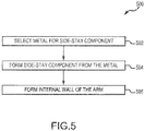
- a thin-skin side-stay beam 102 may be formed by selecting a suitable metal (Step 502).
- the metal may be an aluminum alloy, a titanium alloy, steel, or another suitable metal.
- the metal may also be suitable for e-beam additive manufacturing or WAAM techniques.
- the thin-skin side-stay beams may then be formed from the metal (Step 504).
- the thin-skin side-stay beams may include a lower arm 110 and/or an upper arm 112 as described above.
- An internal wall of the arm may also be formed using additive manufacturing (Step 506).
- Components made using WAAM may include a grain structure grown in the direction of material being added.
- the surfaces of the landing gear components made with additive manufacturing may be smooth. Smooth surfaces and joints may refer to non-welded shapes.
- the landing gear components may also have continuous steps, flanges, and other structures that may be rough when welded. Furthermore, the landing gear components may have internal structural details that cannot be machined into the components due to lack of access.
- Surfaces made using WAAM, EBAM, or similar weld-like techniques may deposit material in a series of cylindrical layers formed one on top of another.
- a wall formed by the techniques may thus have varying width corresponding to the cylindrical profile of each layer.
- the strength of the wall may be limited by the thin portions of the wall.
- the excess material may be removed from each layer during the deposition process.
- forming a thin skin landing gear of the present disclosure using WAAM and/or EBAM manufacturing may also include depositing a layer of material, removing excess material from the layer to give the layer a substantially uniform width, depositing another layer of the layer of uniform width, and removing excess material from the second layer to give the second layer a substantially uniform width. This process would be continued throughout the build of the entire part.
- several layers of material could be deposited, followed by a clean-up process which would remove excess material from the entire wall surface, creating a wall with a substantially uniform width.
- Thin-skin side-stay beams of the present disclosure may tend to reduce weight and increase stiffness, as the curved surfaces and elongated geometry of thin-skinned members use less material to achieve acceptable support levels.
- the thin-skin side-stay beam may also tend to reduce turbulence of air passing by the deployed landing gear with its smooth surfaces and rounded contours. In that regard, thin-skin side-stay beams of the present disclosure may thus tend to minimize noise generated by air rushing past deployed landing gear assemblies. Additionally, the micro structure of the thin-skin side-stay beams may be improved using additive manufacturing techniques.
- references to “one embodiment”, “an embodiment”, “an example embodiment”, etc. indicate that the embodiment described may include a particular feature, structure, or characteristic, but every embodiment may not necessarily include the particular feature, structure, or characteristic. Moreover, such phrases are not necessarily referring to the same embodiment. Further, when a particular feature, structure, or characteristic is described in connection with an embodiment, it is submitted that it is within the knowledge of one skilled in the art to affect such feature, structure, or characteristic in connection with other embodiments whether or not explicitly described. After reading the description, it will be apparent to one skilled in the relevant art(s) how to implement the disclosure in alternative embodiment
Landscapes
- Engineering & Computer Science (AREA)
- Mechanical Engineering (AREA)
- Manufacturing & Machinery (AREA)
- Aviation & Aerospace Engineering (AREA)
- Chemical & Material Sciences (AREA)
- Materials Engineering (AREA)
- Physics & Mathematics (AREA)
- Plasma & Fusion (AREA)
- Optics & Photonics (AREA)
- General Engineering & Computer Science (AREA)
- Powder Metallurgy (AREA)
- Laser Beam Processing (AREA)
Abstract
Description
- The disclosure relates generally to aircraft landing gear, with various embodiments relating to thin-skinned landing gear structures.
- Aircraft designers have continuously tried to increase the fuel efficiency of aircraft over the last century. The fuel efficiency of an aircraft may be related to the aircraft's mass and aerodynamic drag. In addition, noise regulations for aircraft at low altitudes encourage reduction of the aircraft's noise signature while it is near the ground. Landing gear can be heavy and aerodynamically resistant. Additionally, deployed landing gear may increase the noise signature of an aircraft as a result of air rushing past the deployed gear.
- A thin-skin side-stay beam is provided. The side-stay beam may include an upper arm with thin skin and a mating flange extending longitudinally from the thin skin. A lower arm may also have a thin skin and a mating flange extending longitudinally from the lower arm. A joint may include a pin and/or a bushing extending through the mating flanges to pivotally couple the upper arm to the lower arm.
- In various embodiments, the upper arm may have an internal wall extending longitudinally within the thin skin. The internal wall and the thin skin may define an internal cavity having a triangular geometry. The first internal wall may be substantially flat. The triangular geometry may also be convex along the thin skin. A curved surface may blend the first internal wall into the thin skin. The upper arm may also have a second internal wall extending longitudinally within the thin skin. The first internal wall, the second internal wall, and the thin skin may define a second internal cavity having a rectangular geometry. The second internal wall and the thin skin may define a third internal cavity with a triangular geometry. The thin skin may vary in thickness from about 0.07 inches to about 0.125 inches. The upper arm and the lower arm may be made using wire arc additive manufacturing (WAAM) and/or electron beam additive manufacturing (EBAM).
- An arm of a thin-skin side-stay beam is also provided. The arm may include a thin skin elongated in a longitudinal direction. A first mating flange may extend from a first longitudinal end of the thin skin. A second mating flange may also extend from a second longitudinal end of the thin skin. A first internal wall may extend longitudinally within the thin skin. The thin skin and the first internal wall may define a first triangular cavity. A second internal wall may extend longitudinally within the thin skin. The thin skin, the first internal wall, and the second internal wall may define a rectangular cavity. The thin skin and the second internal wall may further define a second triangular cavity.
- In various embodiments, the thin skin may have a thickness ranging from about 0.07 inches to about 0.125 inches. The first inner wall may have a thickness ranging from about 0.025 inches to about 0.25 inches. The first inner wall may also be blended into the thin skin by a curved surface. The curved surface may have a radius of curvature ranging from about 0.5 inches to about 0.8 inches. The first inner wall may be aligned longitudinally with the first mating flange and the second mating flange. The arm may be tapered with the height at the first longitudinal end greater than the height at the second longitudinal end.
- A method of making an arm for a thin-skin side stay is also provided. The method may include the steps of selecting a metal, and forming a thin skin of the arm from the metal using additive manufacturing. The arm may include an internal wall, and the arm may define a plurality of internal cavities.
- In various embodiments, forming the thin-skin of the arm may include depositing a first layer of the metal, removing an excess material from the first layer of the metal, and depositing a second layer of the metal over the first layer of the metal. The method may also include depositing a first layer of the metal, depositing a second layer of the metal over the first layer of the metal, and removing an excess material from the first layer of the metal and the second layer of the metal. The internal wall and arm may define a cavity from the plurality of cavities having a triangular geometry.
- The forgoing features and elements may be combined in various combinations without exclusivity, unless expressly indicated herein otherwise. These features and elements as well as the operation of the disclosed embodiments will become more apparent in light of the following description and accompanying drawings.
- The subject matter of the present disclosure is particularly pointed out and distinctly claimed in the concluding portion of the specification. A more complete understanding of the present disclosures, however, may best be obtained by referring to the detailed description and claims when considered in connection with the drawing figures, wherein like numerals denote like elements.
-
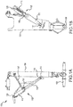
FIG. 1A illustrates a front view of a thin skin landing gear assembly, in accordance with various embodiments; -
FIG. 1B illustrates a side view of a thin skin landing gear assembly, in accordance with various embodiments; -
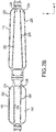
FIG. 2A illustrates a perspective view of a side-stay assembly having a thin-skin architecture, in accordance with various embodiments; -
FIG. 2B illustrates a cross-sectional view of a side-stay assembly having a thin-skin architecture and longitudinally oriented internal walls, in accordance with various embodiments; -
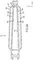
FIG. 3A illustrates a cross-sectional view of a lower arm having internal cavities and longitudinally oriented internal walls, in accordance with various embodiments; -
FIG. 3B illustrates a cross sectional view of a central cavity of a lower arm partially defined by internal walls, in accordance with various embodiments; -
FIG. 3C illustrates a cross-sectional view of the internal cavities of a lower arm, in accordance with various embodiments; -
FIG. 4A illustrates a cross-sectional view of a upper arm having internal cavities and longitudinally oriented internal walls, in accordance with various embodiments; -
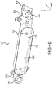
FIG. 4B illustrates a cross sectional view of a central cavity of an upper arm partially defined by internal walls, in accordance with various embodiments; -
FIG. 4C illustrates a cross-sectional view of the internal cavities of an upper arm, in accordance with various embodiments; and -
FIG. 5 illustrates a method of making a thin-skin side-stay beam using additive manufacturing techniques such as wire arc additive manufacturing (WAAM) and/or electron beam additive manufacturing (EBAM), in accordance with various embodiments. - The detailed description of exemplary embodiments herein makes reference to the accompanying drawings, which show exemplary embodiments by way of illustration and their best mode. While these exemplary embodiments are described in sufficient detail to enable those skilled in the art to practice the disclosures, it should be understood that other embodiments may be realized and that logical, chemical, and mechanical changes may be made without departing from the scope of the disclosures. Thus, the detailed description herein is presented for purposes of illustration only and not of limitation. For example, the steps recited in any of the method or process descriptions may be executed in any order and are not necessarily limited to the order presented. Furthermore, any reference to singular includes plural embodiments, and any reference to more than one component or step may include a singular embodiment or step. Also, any reference to attached, fixed, connected or the like may include permanent, removable, temporary, partial, full and/or any other possible attachment option. Additionally, any reference to without contact (or similar phrases) may also include reduced contact or minimal contact.
- The present disclosure relates to landing gear assemblies having aerodynamic thin-skin side-stay beams. Landing gear assemblies may have reduced weight and improved stress distribution by using a hollow-bodied, thin-skin support members and/or side-stays to support the aircraft. This thin-skin design uses thin-skin construction, similar to wing design, to distribute load forces along a greater surface area and thereby enable a reduced cross-section area construction, which reduces the overall mass of the landing gear. Various embodiments of the disclosure provide a smooth, aerodynamic structure, which tends to reduce drag and noise production due to aerodynamic buffeting.
- Referring now to
FIGs. 1A and 1B , an exemplarylanding gear assembly 100 is shown having a thin-skin side-stay beam 102 and thin-skin support member 104, in accordance with various embodiments. Thin-skin side-stay beam 102 may be pivotally coupled tolinkage 106, which is further pivotally coupled to thin-skin support member 104. Thin-skin side-stay beam 102 may also compriselower arm 110 that is pivotally coupled to mounting point 114 of thin-skin support member 104 by joint 116.Lower arm 110 may also be pivotally coupled toupper arm 112 of thin-skin side-stay beam 102 by joint 118. In that regard, thin-skin side-stay beam 102 may comprise anupper arm 112 coupled to alower arm 110 withupper arm 112 being longer thanupper arm 112.Upper arm 112 may further be pivotally coupled to an interface structure at joint 120. - In various embodiments, an
axle 108 may be coupled to thin-skin support member 104 in a perpendicular manner and may be configured to support a rotating wheel assembly. Thin-skin side-stay beam 102 may provide support for thin-skin support member 104 and thereby limit motion of thin-skin support member 104 relative to an aircraft in response tolanding gear assembly 100 being fully deployed. Thin-skin side-stay beam 102 may also provide a pulling force on thin-skin support member 104 at joint 116 and mounting point 114 to stowlanding gear assembly 100. - With reference to
FIG. 2A , a perspective view of thin-skin side-stay beam 102 is shown, in accordance with various embodiments.Lugs 200 may extend longitudinally (with length defined in the x direction, width defined in the y direction, and height defined in the z direction) fromlower arm 110.Joint 116 may include a bushing or pin passed through an opening defined inlugs 200 that have a substantially parallel orientation to one another.Mating flanges 202 may extend longitudinally fromlower arm 110 from the side opposite lugs 200.Joint 118 may include a pin or bushing passed through openings defined inmating flanges 202 oflower arm 110 as well as through openings defined inmating flanges 204 extending longitudinally fromupper arm 112.Lugs 208 may extend longitudinally fromupper arm 112 towards joint 120 for pivotal coupling using a pin and/or bushing.Mating tabs 206 may extend frommating flange 204 and/orupper arm 112 to define openings for coupling tolinkage 106 ofFIG. 1 . - Referring now to
FIGs. 2B ,3A , and4A , cross-sectional views of thin-skin side-stay beam 102 are shown, in accordance with various embodiments. Bothupper arm 112 andlower arm 110 of thin-skin side-stay beam 102 may include hollow internal passages at least partially defined by internal support walls. - In various embodiments,
lower arm 110 has athin skin 226 defining its outer surface and partially defininginternal cavity 220,internal cavity 224, andinternal cavity 230. The outer surface of lower arm andthin skin 226 may be smooth. The outer surface may comprise a tightly-curved leading edge and a less curved side surface for an aerodynamic geometry when the arm is deployed and exposed to wind.Thin skin 226 may vary in thickness from about 60 mils (1.5 mm) to about 400 mils (10.2 mm), from about 70 mils (1.8 mm) to about 125 mils (3.2 mm), or from about 50 mils (1.3 mm) to 500 mils (12.7 mm), or from about 40 mils (1.0 mm) to 600 mils (15.2 mm). As used herein, a mil refers to a thousandth of an inch.Thin skin 226 oflower arm 110 is thus typically less than about 400 mils (10.2 mm) thick, with greater thicknesses used to support greater airframe loads. Lower wall thicknesses forthin skin 226 tend to minimize the weight of thin-skin side-stay beam 102. The thickness circumferentially aroundlower arm 110 may be substantially uniform at a given longitudinal location along the x axis.Thin skin 226 may also be thicker at the longitudinal ends of lower arm 110 (near lugs 200 and mating flanges 202) and thinner at the longitudinal midpoint oflower arm 110. - In various embodiments,
lower arm 110 may includeinternal wall 222 andinternal wall 228.Internal wall 222 andinternal wall 228 may have reflective symmetry. The internal walls may also be non-parallel, with the ends ofinternal wall 222 andinternal wall 228 aligning withlugs 200 andmating flanges 202, both ofFIG. 2A .Internal cavity 220 may thus be defined bythin skin 226 andinternal wall 222.Internal cavity 230 may be defined bythin skin 226 andinternal wall 228.Internal cavity 224 may be defined bythin skin 226,internal wall 222, andinternal wall 228. Internal walls may vary in thickness similar to the above described thicknesses ofthin skin 226. Additionally, internal walls may have a thickness greater thanthin skin 226 in some locations. For example,internal wall 222 andinternal wall 228 may have a thickness ranging from about 125 mils (3.2 mm) to 250 mils (6.4 mm). - In various embodiments,
upper arm 112 has athin skin 232 defining its outer surface and partially defininginternal cavity 234,internal cavity 238, andinternal cavity 242.Thin skin 232 may vary in thickness from about 70 mils (1.8 mm) to about 125 mils (3.2 mm), or from about 60 mils (1.5 mm) to about 400 mils (10.2 mm), from about 50 mils (1.3 mm) to 500 mils (12.7 mm), or from about 40 mils (1.0 mm) to 600 mils (15.2 mm).Thin skin 232 ofupper arm 112 is thus typically less than about 400 mil (10.2 mm) thick, with greater thicknesses used to support greater airframe loads. Lower wall thicknesses forthin skin 232 tend to minimize the weight of thin-skin side-stay beam 102. The thickness aroundupper arm 112 may be substantially uniform at a given longitudinal location along the x axis.Thin skin 232 may be thicker at the longitudinal ends of upper arm 112 (near lugs 208 and mating flanges 204) and thinner at the longitudinal midpoint ofupper arm 112. - In various embodiments,
upper arm 112 may includeinternal wall 236 andinternal wall 240.Internal wall 236 andinternal wall 240 may have reflective symmetry. The internal walls may also be non-parallel, with the ends ofinternal wall 236 andinternal wall 240 aligning withlugs 208 andmating flanges 204, both ofFIG. 2A .Internal cavity 234 may thus be defined bythin skin 232 andinternal wall 236.Internal cavity 242 may be defined bythin skin 232 andinternal wall 240.Internal cavity 238 may be defined bythin skin 232,internal wall 236, andinternal wall 240. Internal walls may vary in thickness similar to the above described thicknesses ofthin skin 232. Additionally, internal walls may have a thickness greater thanthin skin 232 in some locations. For example,internal wall 236 andinternal wall 240 may have a thickness ranging from about 125 mils (3.2 mm) to 250 mils (6.4 mm). - Referring now to
FIG. 3A , the thickness ofinternal wall 222 andinternal wall 228 may vary along the length (i.e., in the x direction) oflower arm 110 and the radius of curvature of the surface joininginternal wall 222 withthin skin 226, orinternal wall 228 withthin skin 226, may vary as well.Curved surface 300 may extend along the length ofinternal wall 228 and may blend a surface ofinternal wall 228 into the internal surface ofthin skin 226.Curved surface 302 may also run along the length ofinternal wall 228 and may blend a surface ofinternal wall 228 into the internal surface ofthin skin 226. The curve of the curved surface may include a radial, multi-radial, oriented perpendicular to the length of internal wall 228 (i.e., in the y-z plane ofFIG. 2A ). The radius of curvature may vary at different longitudinal points along the length oflower arm 110. - In various embodiments,
curved surface 308 may be symmetric tocurved surface 302. Similarly,curved surface 300 may be symmetric tocurved surface 310.Curved surface 302 andcurved surface 308 may have a radius of curvature ranging from 0.5 inches (12.7 mm) to 0.8 inches (20.3 mm). In various embodiments, the radius of curvature ofcurved surface 308 andcurved surface 302 may be may be shorter near the longitudinal center oflower arm 110 than the radius of curvature near the longitudinal ends oflower arm 110.Curved surface 300 andcurved surface 310 may have a substantially uniform curvature of approximately 0.5 inches (12.7 mm), or ranging from 0.5 inches (12.7 mm) to 0.8 inches (20.3 mm). - With reference to
FIG. 3B , a cross sectional view oflower arm 110 taken along the x-z plane is shown, in accordance with various embodiments.Lower arm 110 may have a height D1 (in the z direction) proximate joint 118 andmating flange 202.Lower arm 110 may also have a height D2 (in the z direction) proximate joint 116 andlug 200.Lower arm 110 andinternal cavity 224 may have a tapered height in the longitudinal direction, with D1 greater than D2. In that regard,thin skin 226 may define two non-parallel longitudinal walls when viewed in cross section as shown inFIG. 2B .Curved surface 308 may define a perimeter ofinternal wall 222. - With reference to
FIG. 3C , a cross-sectional view oflower arm 110 taken along the y-z plane is shown, in accordance with various embodiments.Internal cavity 230 may have a triangular cross sectional geometry with curved vertices. Similarly,internal cavity 220 may have a triangular cross sectional geometry with curved vertices. The sides of the triangular geometries may be slightly convex alongthin skin 226 to improve load distribution.Internal wall 228 andinternal wall 222 may be substantially flat.Internal cavity 224 may have a substantially rectangular geometry with the sides alongthin skin 226 having a slightly convex geometry to improve load distribution. The outer surface ofthin skin 226 may have an elongated, oval-like geometry as viewed inFIG. 3C . - Referring now to
FIG. 4A , the thickness ofinternal wall 236 andinternal wall 240 may vary along the length (i.e., in the x direction) ofupper arm 112 and the radius of curvature of the surface joininginternal wall 236 withthin skin 232, orinternal wall 240 withthin skin 232, may vary as well.Curved surface 400 may extend along the length ofinternal wall 240 and may blend a surface ofinternal wall 240 into the internal surface ofthin skin 232.Curved surface 406 may also run along the length ofinternal wall 240 and may blend a surface ofinternal wall 240 into the internal surface ofthin skin 232. The curve of the curved surface may include a radial or multi-radial curve, oriented perpendicular to the length of internal wall 240 (i.e., in the y-z plane ofFIG. 2A ). The radius of curvature may vary at different longitudinal points along the length ofupper arm 112. - In various embodiments,
curved surface 404 may be symmetric tocurved surface 406. Similarly,curved surface 400 may be symmetric tocurved surface 402.Curved surface 406 andcurved surface 404 may have a radius of curvature ranging from 0.5 inches (12.7 mm) to 0.8 inches (20.3 mm). In various embodiments, the radius of curvature ofcurved surface 404 andcurved surface 406 may be may be shorter near the longitudinal center ofupper arm 112 than the radius of curvature near the longitudinal ends ofupper arm 112.Curved surface 400 andcurved surface 402 may have a substantially uniform curvature of approximately 0.5 inches (12.7 mm), or ranging from 0.5 inches (12.7 mm) to 0.8 inches (20.3 mm). - With reference to
FIG. 4B , a cross sectional view ofupper arm 112 taken along the x-z plane is shown, in accordance with various embodiments.Upper arm 112 may have a height D3 (in the z direction) proximate joint 120 andlug 208.Upper arm 112 may also have a height D4 (in the z direction) proximate joint 118 andmating flange 204.Mating flange 204 may include anarm 430 configured to contactlower arm 110 in response to pivotal motion and restrict the range of pivotal motion at joint 118.Upper arm 112 andinternal cavity 238 may have a tapered height in the longitudinal direction, with D3 greater than D4. In that regard,thin skin 232 may define two non-parallel longitudinal walls when viewed in cross section as shown inFIG. 2B .Curved surface 404 may define a perimeter ofinternal wall 236. - With reference to
FIG. 4C , a cross-sectional view ofupper arm 112 taken along the y-z plane is shown, in accordance with various embodiments.Internal cavity 242 may have a triangular geometry with curved vertices. Similarly,internal cavity 234 may have a triangular geometry with curved vertices. The sides of the triangular geometries may be slightly convex alongthin skin 232 to improve load distribution.Internal wall 240 andinternal wall 236 may be substantially flat.Internal cavity 238 may have a substantially rectangular geometry with the sides alongthin skin 232 having a slightly convex geometry to improve load distribution. The outer surface ofthin skin 232 may have an elongated, oval-like geometry as viewed inFIG. 4C . - With reference to
FIG. 5 , anexemplary process 500 for making thin skin landing gear components is shown, in accordance with various embodiments. Any of the various embodiments described herein may be made using additive manufacturing techniques such as direct metal laser sintering, selective laser sintering, selective laser melting, electron-beam melting, electron-beam freeform fabrication, electron beam additive manufacturing (EBAM), or wire arc additive manufacturing (WAAM). WAAM and/or EBAM manufacturing may be used to provide advantageous metallurgic properties in the thin-skin side-stay beams disclosed herein. For example, tensile tests performed on rolled WAAM walls found that the properties of rolled WAAM walls were improved over standard rolled walls and became isotropic. The isotropic material may be worked using cold working process to refine the microstructure and improve the related mechanical properties, thereby making the material anisotropic. The thin-skinned side-stay beams described herein may be made using a grade 5 titanium WAAM deposit such as, for example, Ti-6Al-4V. Grade 5 titanium may include 90% titanium, 6% aluminum, up to 0.25% iron, up to 0.2% oxygen, and 4% vanadium. Other titanium alloys may also be used to make thin-skinned side-stay beams using WAAM techniques. - The experimentally evaluated vertical and horizontal tensile properties of WAAM deposited 2319 aluminum alloy and wrought 2219 aluminum alloy are presented in table T1 below. The vertical (V) direction refers to samples taken across the build layers whilst the horizontal (H) direction refers to those taken along the layers. Yield strength (YS), ultimate tensile strength (UST), and elongation of the WAAM alloy are evenly distributed in the whole as-deposited wall. Average YS and UTS are 110 MPa (16.0 ksi) and 260 MPa (37.7 ksi), respectively. Although the strength values are lower than those of the T851-tempered alloy, they are 50% higher than those of the O-tempered alloy. Meanwhile, the 17% plastic elongation is higher than the T-tempered alloy, which may expand industrial application. In addition to the above mentioned improved metallurgic characteristics, the deposit width in WAAM manufacturing may be 3.5 mm (0.14 in) or lower, reducing the presence of excess material. In various embodiments, a WAAM deposited aluminum alloy such as the aluminum alloy described in table T1 may be used to make thin-skin side-stay beams of the present disclosure. The term approximately is used herein to describe a variance of +\- 10% of the measured values in the tables below.
Table T1 - Tensile properties of WAAM deposited 2319 alloy and wrought 2219 alloy WAAM Alloy Wrought Alloy V1 V2 V3 H1 H2 H3 2219-O 2219-T851 Yield Strength (Mpa) 105 106 107 112 110 121 76 350 Yield Strength (ksi) 15.2 15.4 15.5 16.2 16 17.6 11 50.8 UTS (Mpa) 257 261 256 262 263 263 172 455 UTS(ksi) 37.3 37.9 37.1 38 38.1 38.1 25 66 Elongation (%) 15.4 16.8 14.4 18.3 19 17.8 18 10 - In various embodiments, WAAM may be used to generate thin-skin side-stay beams with the above advantageous material properties including improved plastic elongation, UTS, and yield strength over the O-tempered counterpart. The improved material properties may enable thin-skin side-stay beams to meet standards for operation with reduced weight, as less material may be used in response to improved material properties. WAAM may also enable high build rates of approximately 20 pounds (9.1 kg) per hour.
- Thus, in various embodiments, a thin-skin side-
stay beam 102 may be formed by selecting a suitable metal (Step 502). The metal may be an aluminum alloy, a titanium alloy, steel, or another suitable metal. The metal may also be suitable for e-beam additive manufacturing or WAAM techniques. The thin-skin side-stay beams may then be formed from the metal (Step 504). The thin-skin side-stay beams may include alower arm 110 and/or anupper arm 112 as described above. An internal wall of the arm may also be formed using additive manufacturing (Step 506). - Components made using WAAM may include a grain structure grown in the direction of material being added. The surfaces of the landing gear components made with additive manufacturing may be smooth. Smooth surfaces and joints may refer to non-welded shapes. The landing gear components may also have continuous steps, flanges, and other structures that may be rough when welded. Furthermore, the landing gear components may have internal structural details that cannot be machined into the components due to lack of access.
- Surfaces made using WAAM, EBAM, or similar weld-like techniques may deposit material in a series of cylindrical layers formed one on top of another. A wall formed by the techniques may thus have varying width corresponding to the cylindrical profile of each layer. The strength of the wall, however, may be limited by the thin portions of the wall. Thus, the excess material may be removed from each layer during the deposition process. In that regard, forming a thin skin landing gear of the present disclosure using WAAM and/or EBAM manufacturing may also include depositing a layer of material, removing excess material from the layer to give the layer a substantially uniform width, depositing another layer of the layer of uniform width, and removing excess material from the second layer to give the second layer a substantially uniform width. This process would be continued throughout the build of the entire part. In various embodiments of the build process, several layers of material could be deposited, followed by a clean-up process which would remove excess material from the entire wall surface, creating a wall with a substantially uniform width.
- Thin-skin side-stay beams of the present disclosure may tend to reduce weight and increase stiffness, as the curved surfaces and elongated geometry of thin-skinned members use less material to achieve acceptable support levels. The thin-skin side-stay beam may also tend to reduce turbulence of air passing by the deployed landing gear with its smooth surfaces and rounded contours. In that regard, thin-skin side-stay beams of the present disclosure may thus tend to minimize noise generated by air rushing past deployed landing gear assemblies. Additionally, the micro structure of the thin-skin side-stay beams may be improved using additive manufacturing techniques.
- Benefits, other advantages, and solutions to problems have been described herein with regard to specific embodiments. Furthermore, the connecting lines shown in the various figures contained herein are intended to represent exemplary functional relationships and/or physical couplings between the various elements. It should be noted that many alternative or additional functional relationships or physical connections may be present in a practical system. However, the benefits, advantages, solutions to problems, and any elements that may cause any benefit, advantage, or solution to occur or become more pronounced are not to be construed as critical, required, or essential features or elements of the disclosures.
- The scope of the disclosures is accordingly to be limited by nothing other than the appended claims, in which reference to an element in the singular is not intended to mean "one and only one" unless explicitly so stated, but rather "one or more." Moreover, where a phrase similar to "at least one of A, B, or C" is used in the claims, it is intended that the phrase be interpreted to mean that A alone may be present in an embodiment, B alone may be present in an embodiment, C alone may be present in an embodiment, or that any combination of the elements A, B and C may be present in a single embodiment; for example, A and B, A and C, B and C, or A and B and C. Different cross-hatching is used throughout the figures to denote different parts but not necessarily to denote the same or different materials.
- Systems, methods and apparatus are provided herein. In the detailed description herein, references to "one embodiment", "an embodiment", "an example embodiment", etc., indicate that the embodiment described may include a particular feature, structure, or characteristic, but every embodiment may not necessarily include the particular feature, structure, or characteristic. Moreover, such phrases are not necessarily referring to the same embodiment. Further, when a particular feature, structure, or characteristic is described in connection with an embodiment, it is submitted that it is within the knowledge of one skilled in the art to affect such feature, structure, or characteristic in connection with other embodiments whether or not explicitly described. After reading the description, it will be apparent to one skilled in the relevant art(s) how to implement the disclosure in alternative embodiment
- Furthermore, no element, component, or method step in the present disclosure is intended to be dedicated to the public regardless of whether the element, component, or method step is explicitly recited in the claims. As used herein, the terms "comprises", "comprising", or any other variation thereof, are intended to cover a non-exclusive inclusion, such that a process, method, article, or apparatus that comprises a list of elements does not include only those elements but may include other elements not expressly listed or inherent to such process, method, article, or apparatus.
Claims (15)
- A thin-skin side-stay beam (102), comprising:an upper arm (112) comprising a first thin skin and a first mating flange (202) extending longitudinally from the first thin skin;a lower arm (110) comprising a second thin skin and a second mating flange (204) extending longitudinally from the second thin skin; anda joint (116) comprising at least one of a pin or a bushing extending through the first mating flange (202) and the second mating flange (204) to pivotally couple the upper arm (112) to the lower arm (110).
- The thin-skin side-stay beam of claim 1, wherein the upper arm (112) comprises a first internal wall extending longitudinally within the first thin skin, wherein the first internal wall and the first thin skin define a first internal cavity having a first triangular geometry.
- The thin-skin side-stay beam of claim 2, wherein the first internal wall is substantially flat, and preferably wherein the first triangular geometry is convex along the first thin skin.
- The thin-skin side-stay beam of claim 2, wherein a curved surface blends the first internal wall into the first thin skin.
- The thin-skin side-stay beam of claim 2, wherein the upper arm further comprises a second internal wall extending longitudinally within the first thin skin, wherein the first internal wall, the second internal wall, and the first thin skin define a second internal cavity having a rectangular geometry, and preferably wherein the second internal wall and the first thin skin define a third internal cavity having a second triangular geometry.
- The thin-skin side-stay beam of claim 1, wherein the first thin skin has a thickness ranging from about 70 mils to about 125 mils.
- The thin-skin side-stay beam of claim 1, wherein the upper arm (112) and the lower arm (110) are made using at least one of wire arc additive manufacturing or electron beam additive manufacturing.
- An arm of a thin-skin side-stay beam, comprising:a thin skin elongated in a longitudinal direction with a first mating flange extending from a first longitudinal end of the thin skin and a second mating flange extending from a second longitudinal end of the thin skin;a first internal wall extending longitudinally within the thin skin, wherein the thin skin and the first internal wall define a first triangular cavity; anda second internal wall extending longitudinally within the thin skin, wherein the thin skin, the first internal wall, and the second internal wall define a rectangular cavity, wherein the thin skin and the second internal wall define a second triangular cavity.
- The ann of claim 8, wherein the thin skin has a thickness ranging from about 0.07 inches to about 0.125 inches.
- The arm of claim 9, wherein the first internal wall has a thickness ranging from about 0.125 inches to about 0.25 inches, and preferably wherein the first internal wall is blended into the thin skin by a curved surface, and more preferably wherein the curved surface has a radius of curvature ranging from about 0.5 inches to about 0.8 inches.
- The arm of claim 8, wherein the first internal wall is aligned longitudinally with the first mating flange and the second mating flange.
- The arm of claim 8, wherein the arm has a first height at the first longitudinal end of the thin skin and a second height at the second longitudinal end of the thin skin and the first height is greater than the second height.
- A method of making an arm for a thin-skin side stay beam, comprising:selecting a metal;forming a thin skin of the arm from the metal using additive manufacturing, wherein the thin skin and the internal wall at least partially define a plurality of internal cavities; andforming an internal wall of the arm using additive manufacturing.
- The method of claim 13, wherein the forming the thin skin of the arm comprises:depositing a first layer of the metal;removing an excess material from the first layer of the metal; anddepositing a second layer of the metal over the first layer of the metal.
- The method of claim 13, wherein the forming the thin skin of the arm comprises:depositing a first layer of the metal;depositing a second layer of the metal over the first layer of the metal; andremoving an excess material from the first layer of the metal and the second layer of the metal; or wherein the internal wall and the thin skin define an internal cavity of the plurality of internal cavities, wherein the cavity has a triangular geometry.
Applications Claiming Priority (1)
| Application Number | Priority Date | Filing Date | Title |
|---|---|---|---|
| US15/222,772 US10563690B2 (en) | 2016-07-28 | 2016-07-28 | Thin-skin side stay beams and landing gear assemblies |
Publications (2)
| Publication Number | Publication Date |
|---|---|
| EP3275780A1 true EP3275780A1 (en) | 2018-01-31 |
| EP3275780B1 EP3275780B1 (en) | 2019-03-13 |
Family
ID=59014538
Family Applications (1)
| Application Number | Title | Priority Date | Filing Date |
|---|---|---|---|
| EP17174624.1A Active EP3275780B1 (en) | 2016-07-28 | 2017-06-06 | Thin-skin side stay beams and landing gear assemblies |
Country Status (2)
| Country | Link |
|---|---|
| US (3) | US10563690B2 (en) |
| EP (1) | EP3275780B1 (en) |
Cited By (7)
| Publication number | Priority date | Publication date | Assignee | Title |
|---|---|---|---|---|
| CN109774922A (en) * | 2019-01-22 | 2019-05-21 | 南京航空航天大学 | It is a kind of become grounding point master play landing gear |
| EP3604127A1 (en) * | 2018-08-02 | 2020-02-05 | Safran Landing Systems UK Limited | Aircraft landing gear assembly |
| CN110901899A (en) * | 2018-09-17 | 2020-03-24 | 赛峰起落架系统英国有限公司 | Aircraft landing gear component |
| EP3736210A1 (en) * | 2019-05-10 | 2020-11-11 | Goodrich Corporation | Additively manufactured landing gear with hydraulic fluid channels |
| FR3098493A1 (en) * | 2019-07-12 | 2021-01-15 | Safran Landing Systems | LANDING WITH REINFORCEMENT SAIL |
| US11167865B2 (en) | 2019-05-10 | 2021-11-09 | Goodrich Corporation | Additively manufactured lubrication channels |
| US11912400B2 (en) | 2021-09-28 | 2024-02-27 | Airbus Operations Limited | Landing gear stay |
Families Citing this family (6)
| Publication number | Priority date | Publication date | Assignee | Title |
|---|---|---|---|---|
| US10563690B2 (en) * | 2016-07-28 | 2020-02-18 | Goodrich Corporation | Thin-skin side stay beams and landing gear assemblies |
| US11426818B2 (en) | 2018-08-10 | 2022-08-30 | The Research Foundation for the State University | Additive manufacturing processes and additively manufactured products |
| US20200189494A1 (en) * | 2018-12-13 | 2020-06-18 | Safran Landing Systems Canada Inc. | Landing gear structure with harness |
| CN112319783A (en) * | 2021-01-04 | 2021-02-05 | 尚良仲毅(沈阳)高新科技有限公司 | System and unmanned aerial vehicle rise and fall |
| US11708150B2 (en) * | 2021-02-09 | 2023-07-25 | Safran Landing Systems Canada Inc. | Hybrid main landing gear fitting with detachable drag arm |
| US12365028B2 (en) * | 2022-03-04 | 2025-07-22 | Goodrich Corporation | Systems and methods for manufacturing landing gear components using titanium |
Citations (5)
| Publication number | Priority date | Publication date | Assignee | Title |
|---|---|---|---|---|
| US2421871A (en) * | 1942-07-22 | 1947-06-10 | Dowty George Herbert | Leg structure for mounting aircraft landing elements |
| US20130112309A1 (en) * | 2011-11-03 | 2013-05-09 | The Boeing Company | Tubular Composite Strut Having Internal Stiffening and Method for Making the Same |
| US20150034762A1 (en) * | 2013-08-02 | 2015-02-05 | Goodrich Corporation | Routings for articulated landing gear |
| WO2015053940A1 (en) * | 2013-10-07 | 2015-04-16 | United Technologies Corporation | Additively grown enhanced impact resistance features for improved structure and joint protection |
| CN105109673A (en) * | 2015-08-25 | 2015-12-02 | 中国运载火箭技术研究院 | Large-loading multi-point coordinated undercarriage fixed connection structure |
Family Cites Families (11)
| Publication number | Priority date | Publication date | Assignee | Title |
|---|---|---|---|---|
| US2395690A (en) | 1941-11-10 | 1946-02-26 | Smith Corp A O | Welded pressed metal landing gear strut |
| US2441871A (en) | 1944-04-04 | 1948-05-18 | Harry M Burt | Lamp holder for fluorescent lamps |
| FR2450199A1 (en) * | 1978-12-29 | 1980-09-26 | Messier Hispano Sa | PRINCIPAL LANDING AND SIDE LIFT LANDING GEAR FOR AIRCRAFT |
| FR2511338A1 (en) * | 1981-08-12 | 1983-02-18 | Messier Hispano Sa | LANDING TRAIN FOR AIRCRAFT |
| US6349901B1 (en) | 2000-08-30 | 2002-02-26 | Northrop Grumman Corporation | Landing gear |
| US6955023B2 (en) * | 2000-12-13 | 2005-10-18 | Kevin Chaite Rotheroe | Unitary metal structural member with internal reinforcement |
| FR2887601B1 (en) * | 2005-06-24 | 2007-10-05 | Snecma Moteurs Sa | MECHANICAL PIECE AND METHOD FOR MANUFACTURING SUCH A PART |
| GB0814291D0 (en) | 2008-08-05 | 2008-09-10 | Airbus Uk Ltd | Landing gear with noise reduction fairing |
| FR3017819B1 (en) * | 2014-02-25 | 2016-03-25 | Snecma | FIBROUS REINFORCEMENT FOR CARRYING OUT AN EXTENDED MECHANICAL PIECE OF COMPOSITE MATERIAL |
| CN105109637A (en) | 2015-08-31 | 2015-12-02 | 江阴市船舶设备制造有限公司 | Ship fender strip |
| US10563690B2 (en) * | 2016-07-28 | 2020-02-18 | Goodrich Corporation | Thin-skin side stay beams and landing gear assemblies |
-
2016
- 2016-07-28 US US15/222,772 patent/US10563690B2/en active Active
-
2017
- 2017-06-06 EP EP17174624.1A patent/EP3275780B1/en active Active
-
2019
- 2019-09-06 US US16/563,419 patent/US11827341B2/en active Active
- 2019-09-06 US US16/563,387 patent/US10590982B2/en active Active
Patent Citations (5)
| Publication number | Priority date | Publication date | Assignee | Title |
|---|---|---|---|---|
| US2421871A (en) * | 1942-07-22 | 1947-06-10 | Dowty George Herbert | Leg structure for mounting aircraft landing elements |
| US20130112309A1 (en) * | 2011-11-03 | 2013-05-09 | The Boeing Company | Tubular Composite Strut Having Internal Stiffening and Method for Making the Same |
| US20150034762A1 (en) * | 2013-08-02 | 2015-02-05 | Goodrich Corporation | Routings for articulated landing gear |
| WO2015053940A1 (en) * | 2013-10-07 | 2015-04-16 | United Technologies Corporation | Additively grown enhanced impact resistance features for improved structure and joint protection |
| CN105109673A (en) * | 2015-08-25 | 2015-12-02 | 中国运载火箭技术研究院 | Large-loading multi-point coordinated undercarriage fixed connection structure |
Cited By (14)
| Publication number | Priority date | Publication date | Assignee | Title |
|---|---|---|---|---|
| EP3604127A1 (en) * | 2018-08-02 | 2020-02-05 | Safran Landing Systems UK Limited | Aircraft landing gear assembly |
| WO2020025439A1 (en) * | 2018-08-02 | 2020-02-06 | Safran Landing Systems Uk Ltd | Aircraft landing gear assembly |
| US11613346B2 (en) | 2018-08-02 | 2023-03-28 | Safran Landing Systems Uk Ltd | Aircraft landing gear assembly and method |
| CN110901899A (en) * | 2018-09-17 | 2020-03-24 | 赛峰起落架系统英国有限公司 | Aircraft landing gear component |
| CN110901899B (en) * | 2018-09-17 | 2024-03-26 | 赛峰起落架系统英国有限公司 | Aircraft landing gear component |
| CN109774922B (en) * | 2019-01-22 | 2022-01-18 | 南京航空航天大学 | Main land playing device of variable grounding point |
| CN109774922A (en) * | 2019-01-22 | 2019-05-21 | 南京航空航天大学 | It is a kind of become grounding point master play landing gear |
| US11312483B2 (en) | 2019-05-10 | 2022-04-26 | Goodrich Corporation | Landing gear with hydraulic fluid channels |
| US11167865B2 (en) | 2019-05-10 | 2021-11-09 | Goodrich Corporation | Additively manufactured lubrication channels |
| EP3736210A1 (en) * | 2019-05-10 | 2020-11-11 | Goodrich Corporation | Additively manufactured landing gear with hydraulic fluid channels |
| WO2021009065A1 (en) * | 2019-07-12 | 2021-01-21 | Safran Landing Systems | Landing gear with reinforcing web |
| FR3098493A1 (en) * | 2019-07-12 | 2021-01-15 | Safran Landing Systems | LANDING WITH REINFORCEMENT SAIL |
| US11753153B2 (en) | 2019-07-12 | 2023-09-12 | Safran Landing Systems | Landing gear with reinforcing web |
| US11912400B2 (en) | 2021-09-28 | 2024-02-27 | Airbus Operations Limited | Landing gear stay |
Also Published As
| Publication number | Publication date |
|---|---|
| US11827341B2 (en) | 2023-11-28 |
| US10563690B2 (en) | 2020-02-18 |
| US20180031028A1 (en) | 2018-02-01 |
| US20200018345A1 (en) | 2020-01-16 |
| US10590982B2 (en) | 2020-03-17 |
| EP3275780B1 (en) | 2019-03-13 |
| US20200003251A1 (en) | 2020-01-02 |
Similar Documents
| Publication | Publication Date | Title |
|---|---|---|
| US10590982B2 (en) | Thin-skin side stay beams and landing gear assemblies | |
| US11685520B2 (en) | Aerodynamic noise reducing thin-skin landing gear structures and manufacturing techniques | |
| US7716835B2 (en) | Methods of manufacturing structural panels | |
| US8087614B2 (en) | Stringer for an aircraft wing and a method of forming thereof | |
| US9580164B2 (en) | Apparatus and methods for joining aircraft composite structures | |
| RU2438924C2 (en) | Aircraft wing stringer and method of its production | |
| WO2019048682A1 (en) | GENERATED BATTERY MOUNT | |
| JP2016175631A (en) | Composite fixed edge of aircraft wing and its mounting method | |
| EP0850113A1 (en) | Reinforced formed part, process for its production and its use | |
| US11084574B2 (en) | Aerodynamic noise reducing thin-skin landing gear structure | |
| DE202012002493U1 (en) | helicopter tail | |
| DE102010035212A1 (en) | Body structure of a motor vehicle, motor vehicle and method for producing a body structure | |
| DE102006026169B4 (en) | Aircraft fuselage structure and method for its manufacture | |
| WO2008080027A1 (en) | Seat track assembly | |
| EP3162699B1 (en) | Structural assembly, air or spacecraft and method for producing a structural assembly | |
| CN108137147A (en) | Airframe structure and manufacturing method without longeron | |
| DE102010012486A1 (en) | Suspension of a vehicle and method for producing a cross member thereof | |
| US20170297676A1 (en) | Hat section door frame with integral gussets | |
| CN108238261B (en) | Main structure for a support for an aircraft propeller group comprising a pyramidal section with convergent struts | |
| DE102006026170A1 (en) | Aircraft fuselage structure and method for its manufacture | |
| EP3088295A1 (en) | Modular propulsion unit nozzle | |
| CN218489895U (en) | Unmanned aerial vehicle variable cross section combined material tail-boom structure | |
| CN121025898A (en) | A multi-functional cabin structure with large cone angle composite material skin stringers | |
| Coombe et al. | Some Present Uses and Future Prospects of Titanium in Airframes |
Legal Events
| Date | Code | Title | Description |
|---|---|---|---|
| PUAI | Public reference made under article 153(3) epc to a published international application that has entered the european phase |
Free format text: ORIGINAL CODE: 0009012 |
|
| STAA | Information on the status of an ep patent application or granted ep patent |
Free format text: STATUS: THE APPLICATION HAS BEEN PUBLISHED |
|
| AK | Designated contracting states |
Kind code of ref document: A1 Designated state(s): AL AT BE BG CH CY CZ DE DK EE ES FI FR GB GR HR HU IE IS IT LI LT LU LV MC MK MT NL NO PL PT RO RS SE SI SK SM TR |
|
| AX | Request for extension of the european patent |
Extension state: BA ME |
|
| STAA | Information on the status of an ep patent application or granted ep patent |
Free format text: STATUS: REQUEST FOR EXAMINATION WAS MADE |
|
| 17P | Request for examination filed |
Effective date: 20180731 |
|
| RBV | Designated contracting states (corrected) |
Designated state(s): AL AT BE BG CH CY CZ DE DK EE ES FI FR GB GR HR HU IE IS IT LI LT LU LV MC MK MT NL NO PL PT RO RS SE SI SK SM TR |
|
| GRAP | Despatch of communication of intention to grant a patent |
Free format text: ORIGINAL CODE: EPIDOSNIGR1 |
|
| STAA | Information on the status of an ep patent application or granted ep patent |
Free format text: STATUS: GRANT OF PATENT IS INTENDED |
|
| INTG | Intention to grant announced |
Effective date: 20181004 |
|
| GRAS | Grant fee paid |
Free format text: ORIGINAL CODE: EPIDOSNIGR3 |
|
| GRAA | (expected) grant |
Free format text: ORIGINAL CODE: 0009210 |
|
| STAA | Information on the status of an ep patent application or granted ep patent |
Free format text: STATUS: THE PATENT HAS BEEN GRANTED |
|
| AK | Designated contracting states |
Kind code of ref document: B1 Designated state(s): AL AT BE BG CH CY CZ DE DK EE ES FI FR GB GR HR HU IE IS IT LI LT LU LV MC MK MT NL NO PL PT RO RS SE SI SK SM TR |
|
| REG | Reference to a national code |
Ref country code: GB Ref legal event code: FG4D |
|
| REG | Reference to a national code |
Ref country code: CH Ref legal event code: EP Ref country code: AT Ref legal event code: REF Ref document number: 1107359 Country of ref document: AT Kind code of ref document: T Effective date: 20190315 |
|
| REG | Reference to a national code |
Ref country code: IE Ref legal event code: FG4D |
|
| REG | Reference to a national code |
Ref country code: DE Ref legal event code: R096 Ref document number: 602017002643 Country of ref document: DE |
|
| REG | Reference to a national code |
Ref country code: NL Ref legal event code: MP Effective date: 20190313 |
|
| REG | Reference to a national code |
Ref country code: LT Ref legal event code: MG4D |
|
| PG25 | Lapsed in a contracting state [announced via postgrant information from national office to epo] |
Ref country code: LT Free format text: LAPSE BECAUSE OF FAILURE TO SUBMIT A TRANSLATION OF THE DESCRIPTION OR TO PAY THE FEE WITHIN THE PRESCRIBED TIME-LIMIT Effective date: 20190313 Ref country code: FI Free format text: LAPSE BECAUSE OF FAILURE TO SUBMIT A TRANSLATION OF THE DESCRIPTION OR TO PAY THE FEE WITHIN THE PRESCRIBED TIME-LIMIT Effective date: 20190313 Ref country code: NO Free format text: LAPSE BECAUSE OF FAILURE TO SUBMIT A TRANSLATION OF THE DESCRIPTION OR TO PAY THE FEE WITHIN THE PRESCRIBED TIME-LIMIT Effective date: 20190613 Ref country code: SE Free format text: LAPSE BECAUSE OF FAILURE TO SUBMIT A TRANSLATION OF THE DESCRIPTION OR TO PAY THE FEE WITHIN THE PRESCRIBED TIME-LIMIT Effective date: 20190313 |
|
| PG25 | Lapsed in a contracting state [announced via postgrant information from national office to epo] |
Ref country code: NL Free format text: LAPSE BECAUSE OF FAILURE TO SUBMIT A TRANSLATION OF THE DESCRIPTION OR TO PAY THE FEE WITHIN THE PRESCRIBED TIME-LIMIT Effective date: 20190313 Ref country code: RS Free format text: LAPSE BECAUSE OF FAILURE TO SUBMIT A TRANSLATION OF THE DESCRIPTION OR TO PAY THE FEE WITHIN THE PRESCRIBED TIME-LIMIT Effective date: 20190313 Ref country code: BG Free format text: LAPSE BECAUSE OF FAILURE TO SUBMIT A TRANSLATION OF THE DESCRIPTION OR TO PAY THE FEE WITHIN THE PRESCRIBED TIME-LIMIT Effective date: 20190613 Ref country code: LV Free format text: LAPSE BECAUSE OF FAILURE TO SUBMIT A TRANSLATION OF THE DESCRIPTION OR TO PAY THE FEE WITHIN THE PRESCRIBED TIME-LIMIT Effective date: 20190313 Ref country code: GR Free format text: LAPSE BECAUSE OF FAILURE TO SUBMIT A TRANSLATION OF THE DESCRIPTION OR TO PAY THE FEE WITHIN THE PRESCRIBED TIME-LIMIT Effective date: 20190614 Ref country code: HR Free format text: LAPSE BECAUSE OF FAILURE TO SUBMIT A TRANSLATION OF THE DESCRIPTION OR TO PAY THE FEE WITHIN THE PRESCRIBED TIME-LIMIT Effective date: 20190313 |
|
| REG | Reference to a national code |
Ref country code: AT Ref legal event code: MK05 Ref document number: 1107359 Country of ref document: AT Kind code of ref document: T Effective date: 20190313 |
|
| PG25 | Lapsed in a contracting state [announced via postgrant information from national office to epo] |
Ref country code: PT Free format text: LAPSE BECAUSE OF FAILURE TO SUBMIT A TRANSLATION OF THE DESCRIPTION OR TO PAY THE FEE WITHIN THE PRESCRIBED TIME-LIMIT Effective date: 20190713 Ref country code: AL Free format text: LAPSE BECAUSE OF FAILURE TO SUBMIT A TRANSLATION OF THE DESCRIPTION OR TO PAY THE FEE WITHIN THE PRESCRIBED TIME-LIMIT Effective date: 20190313 Ref country code: IT Free format text: LAPSE BECAUSE OF FAILURE TO SUBMIT A TRANSLATION OF THE DESCRIPTION OR TO PAY THE FEE WITHIN THE PRESCRIBED TIME-LIMIT Effective date: 20190313 Ref country code: EE Free format text: LAPSE BECAUSE OF FAILURE TO SUBMIT A TRANSLATION OF THE DESCRIPTION OR TO PAY THE FEE WITHIN THE PRESCRIBED TIME-LIMIT Effective date: 20190313 Ref country code: SK Free format text: LAPSE BECAUSE OF FAILURE TO SUBMIT A TRANSLATION OF THE DESCRIPTION OR TO PAY THE FEE WITHIN THE PRESCRIBED TIME-LIMIT Effective date: 20190313 Ref country code: CZ Free format text: LAPSE BECAUSE OF FAILURE TO SUBMIT A TRANSLATION OF THE DESCRIPTION OR TO PAY THE FEE WITHIN THE PRESCRIBED TIME-LIMIT Effective date: 20190313 Ref country code: RO Free format text: LAPSE BECAUSE OF FAILURE TO SUBMIT A TRANSLATION OF THE DESCRIPTION OR TO PAY THE FEE WITHIN THE PRESCRIBED TIME-LIMIT Effective date: 20190313 Ref country code: ES Free format text: LAPSE BECAUSE OF FAILURE TO SUBMIT A TRANSLATION OF THE DESCRIPTION OR TO PAY THE FEE WITHIN THE PRESCRIBED TIME-LIMIT Effective date: 20190313 |
|
| PG25 | Lapsed in a contracting state [announced via postgrant information from national office to epo] |
Ref country code: PL Free format text: LAPSE BECAUSE OF FAILURE TO SUBMIT A TRANSLATION OF THE DESCRIPTION OR TO PAY THE FEE WITHIN THE PRESCRIBED TIME-LIMIT Effective date: 20190313 Ref country code: SM Free format text: LAPSE BECAUSE OF FAILURE TO SUBMIT A TRANSLATION OF THE DESCRIPTION OR TO PAY THE FEE WITHIN THE PRESCRIBED TIME-LIMIT Effective date: 20190313 |
|
| REG | Reference to a national code |
Ref country code: DE Ref legal event code: R097 Ref document number: 602017002643 Country of ref document: DE |
|
| PG25 | Lapsed in a contracting state [announced via postgrant information from national office to epo] |
Ref country code: IS Free format text: LAPSE BECAUSE OF FAILURE TO SUBMIT A TRANSLATION OF THE DESCRIPTION OR TO PAY THE FEE WITHIN THE PRESCRIBED TIME-LIMIT Effective date: 20190713 Ref country code: AT Free format text: LAPSE BECAUSE OF FAILURE TO SUBMIT A TRANSLATION OF THE DESCRIPTION OR TO PAY THE FEE WITHIN THE PRESCRIBED TIME-LIMIT Effective date: 20190313 |
|
| PLBE | No opposition filed within time limit |
Free format text: ORIGINAL CODE: 0009261 |
|
| STAA | Information on the status of an ep patent application or granted ep patent |
Free format text: STATUS: NO OPPOSITION FILED WITHIN TIME LIMIT |
|
| PG25 | Lapsed in a contracting state [announced via postgrant information from national office to epo] |
Ref country code: MC Free format text: LAPSE BECAUSE OF FAILURE TO SUBMIT A TRANSLATION OF THE DESCRIPTION OR TO PAY THE FEE WITHIN THE PRESCRIBED TIME-LIMIT Effective date: 20190313 Ref country code: DK Free format text: LAPSE BECAUSE OF FAILURE TO SUBMIT A TRANSLATION OF THE DESCRIPTION OR TO PAY THE FEE WITHIN THE PRESCRIBED TIME-LIMIT Effective date: 20190313 |
|
| 26N | No opposition filed |
Effective date: 20191216 |
|
| PG25 | Lapsed in a contracting state [announced via postgrant information from national office to epo] |
Ref country code: SI Free format text: LAPSE BECAUSE OF FAILURE TO SUBMIT A TRANSLATION OF THE DESCRIPTION OR TO PAY THE FEE WITHIN THE PRESCRIBED TIME-LIMIT Effective date: 20190313 |
|
| REG | Reference to a national code |
Ref country code: BE Ref legal event code: MM Effective date: 20190630 |
|
| PG25 | Lapsed in a contracting state [announced via postgrant information from national office to epo] |
Ref country code: TR Free format text: LAPSE BECAUSE OF FAILURE TO SUBMIT A TRANSLATION OF THE DESCRIPTION OR TO PAY THE FEE WITHIN THE PRESCRIBED TIME-LIMIT Effective date: 20190313 |
|
| PG25 | Lapsed in a contracting state [announced via postgrant information from national office to epo] |
Ref country code: IE Free format text: LAPSE BECAUSE OF NON-PAYMENT OF DUE FEES Effective date: 20190606 |
|
| PG25 | Lapsed in a contracting state [announced via postgrant information from national office to epo] |
Ref country code: LU Free format text: LAPSE BECAUSE OF NON-PAYMENT OF DUE FEES Effective date: 20190606 Ref country code: BE Free format text: LAPSE BECAUSE OF NON-PAYMENT OF DUE FEES Effective date: 20190630 |
|
| REG | Reference to a national code |
Ref country code: CH Ref legal event code: PL |
|
| PG25 | Lapsed in a contracting state [announced via postgrant information from national office to epo] |
Ref country code: CH Free format text: LAPSE BECAUSE OF NON-PAYMENT OF DUE FEES Effective date: 20200630 Ref country code: LI Free format text: LAPSE BECAUSE OF NON-PAYMENT OF DUE FEES Effective date: 20200630 |
|
| PG25 | Lapsed in a contracting state [announced via postgrant information from national office to epo] |
Ref country code: CY Free format text: LAPSE BECAUSE OF FAILURE TO SUBMIT A TRANSLATION OF THE DESCRIPTION OR TO PAY THE FEE WITHIN THE PRESCRIBED TIME-LIMIT Effective date: 20190313 |
|
| PG25 | Lapsed in a contracting state [announced via postgrant information from national office to epo] |
Ref country code: MT Free format text: LAPSE BECAUSE OF FAILURE TO SUBMIT A TRANSLATION OF THE DESCRIPTION OR TO PAY THE FEE WITHIN THE PRESCRIBED TIME-LIMIT Effective date: 20190313 Ref country code: HU Free format text: LAPSE BECAUSE OF FAILURE TO SUBMIT A TRANSLATION OF THE DESCRIPTION OR TO PAY THE FEE WITHIN THE PRESCRIBED TIME-LIMIT; INVALID AB INITIO Effective date: 20170606 |
|
| GBPC | Gb: european patent ceased through non-payment of renewal fee |
Effective date: 20210606 |
|
| PG25 | Lapsed in a contracting state [announced via postgrant information from national office to epo] |
Ref country code: GB Free format text: LAPSE BECAUSE OF NON-PAYMENT OF DUE FEES Effective date: 20210606 |
|
| PG25 | Lapsed in a contracting state [announced via postgrant information from national office to epo] |
Ref country code: MK Free format text: LAPSE BECAUSE OF FAILURE TO SUBMIT A TRANSLATION OF THE DESCRIPTION OR TO PAY THE FEE WITHIN THE PRESCRIBED TIME-LIMIT Effective date: 20190313 |
|
| PGFP | Annual fee paid to national office [announced via postgrant information from national office to epo] |
Ref country code: DE Payment date: 20250520 Year of fee payment: 9 |
|
| PGFP | Annual fee paid to national office [announced via postgrant information from national office to epo] |
Ref country code: FR Payment date: 20250520 Year of fee payment: 9 |
|
| P01 | Opt-out of the competence of the unified patent court (upc) registered |
Free format text: CASE NUMBER: UPC_APP_0017246_3275780/2025 Effective date: 20251211 |