EP3275778A1 - Curved aircraft substructure repairs systems and methods - Google Patents
Curved aircraft substructure repairs systems and methods Download PDFInfo
- Publication number
- EP3275778A1 EP3275778A1 EP17168285.9A EP17168285A EP3275778A1 EP 3275778 A1 EP3275778 A1 EP 3275778A1 EP 17168285 A EP17168285 A EP 17168285A EP 3275778 A1 EP3275778 A1 EP 3275778A1
- Authority
- EP
- European Patent Office
- Prior art keywords
- stock
- aircraft
- leg
- curved
- flanges
- Prior art date
- Legal status (The legal status is an assumption and is not a legal conclusion. Google has not performed a legal analysis and makes no representation as to the accuracy of the status listed.)
- Granted
Links
- 238000000034 method Methods 0.000 title claims abstract description 44
- 230000008439 repair process Effects 0.000 title abstract description 85
- 238000005452 bending Methods 0.000 claims abstract description 14
- 238000005520 cutting process Methods 0.000 claims abstract description 8
- 238000010168 coupling process Methods 0.000 claims description 30
- 230000008878 coupling Effects 0.000 claims description 29
- 238000005859 coupling reaction Methods 0.000 claims description 29
- 238000009966 trimming Methods 0.000 claims description 13
- 239000003351 stiffener Substances 0.000 abstract description 75
- 230000008569 process Effects 0.000 description 3
- 229910052782 aluminium Inorganic materials 0.000 description 2
- XAGFODPZIPBFFR-UHFFFAOYSA-N aluminium Chemical compound [Al] XAGFODPZIPBFFR-UHFFFAOYSA-N 0.000 description 2
- 239000002131 composite material Substances 0.000 description 2
- 238000003698 laser cutting Methods 0.000 description 2
- 238000003754 machining Methods 0.000 description 2
- 229910052751 metal Inorganic materials 0.000 description 2
- 239000002184 metal Substances 0.000 description 2
- 150000002739 metals Chemical class 0.000 description 2
- 239000003381 stabilizer Substances 0.000 description 2
- 229920000049 Carbon (fiber) Polymers 0.000 description 1
- RYGMFSIKBFXOCR-UHFFFAOYSA-N Copper Chemical compound [Cu] RYGMFSIKBFXOCR-UHFFFAOYSA-N 0.000 description 1
- 229910000831 Steel Inorganic materials 0.000 description 1
- RTAQQCXQSZGOHL-UHFFFAOYSA-N Titanium Chemical compound [Ti] RTAQQCXQSZGOHL-UHFFFAOYSA-N 0.000 description 1
- 238000005219 brazing Methods 0.000 description 1
- 239000004917 carbon fiber Substances 0.000 description 1
- 229910052802 copper Inorganic materials 0.000 description 1
- 239000010949 copper Substances 0.000 description 1
- 230000000694 effects Effects 0.000 description 1
- 239000011152 fibreglass Substances 0.000 description 1
- 239000000463 material Substances 0.000 description 1
- VNWKTOKETHGBQD-UHFFFAOYSA-N methane Chemical compound C VNWKTOKETHGBQD-UHFFFAOYSA-N 0.000 description 1
- 238000012986 modification Methods 0.000 description 1
- 230000004048 modification Effects 0.000 description 1
- 239000010959 steel Substances 0.000 description 1
- 230000002459 sustained effect Effects 0.000 description 1
- 239000010936 titanium Substances 0.000 description 1
- 229910052719 titanium Inorganic materials 0.000 description 1
- 238000003466 welding Methods 0.000 description 1
- 239000002023 wood Substances 0.000 description 1
Images



Classifications
-
- B—PERFORMING OPERATIONS; TRANSPORTING
- B64—AIRCRAFT; AVIATION; COSMONAUTICS
- B64F—GROUND OR AIRCRAFT-CARRIER-DECK INSTALLATIONS SPECIALLY ADAPTED FOR USE IN CONNECTION WITH AIRCRAFT; DESIGNING, MANUFACTURING, ASSEMBLING, CLEANING, MAINTAINING OR REPAIRING AIRCRAFT, NOT OTHERWISE PROVIDED FOR; HANDLING, TRANSPORTING, TESTING OR INSPECTING AIRCRAFT COMPONENTS, NOT OTHERWISE PROVIDED FOR
- B64F5/00—Designing, manufacturing, assembling, cleaning, maintaining or repairing aircraft, not otherwise provided for; Handling, transporting, testing or inspecting aircraft components, not otherwise provided for
- B64F5/40—Maintaining or repairing aircraft
-
- B—PERFORMING OPERATIONS; TRANSPORTING
- B64—AIRCRAFT; AVIATION; COSMONAUTICS
- B64C—AEROPLANES; HELICOPTERS
- B64C1/00—Fuselages; Constructional features common to fuselages, wings, stabilising surfaces or the like
- B64C1/06—Frames; Stringers; Longerons ; Fuselage sections
- B64C1/061—Frames
-
- B—PERFORMING OPERATIONS; TRANSPORTING
- B64—AIRCRAFT; AVIATION; COSMONAUTICS
- B64C—AEROPLANES; HELICOPTERS
- B64C1/00—Fuselages; Constructional features common to fuselages, wings, stabilising surfaces or the like
- B64C1/06—Frames; Stringers; Longerons ; Fuselage sections
- B64C1/12—Construction or attachment of skin panels
Definitions
- the disclosure relates generally to aircraft and more specifically to repairing curved aircraft structures.
- Aircraft fuselages and other structures may be curved. Repair of curved structures require entire substructures to be replaced with prefabricated spare parts. The spare parts are expensive and must be ordered, resulting in extended downtime for aircrafts being repaired.
- a method may be disclosed. The method may include trimming a first stock into a blank shape, cutting a plurality of slits into the first stock, bending the first stock at least a plurality of times, where the bent first stock comprises a leg portion configured to be coupled to an aircraft, a side portion coupled to the leg portion, and a top portion coupled to the side portion, and where the leg portion and the side portion include the plurality of slits and the plurality of slits divides the leg portion into a plurality of leg flanges and the side portion into a plurality of side flanges, coupling the leg portion to a curved portion of the aircraft, where the leg portion substantially conforms to a curvature of the curved portion, and fastening the leg portion to the aircraft.
- the leg portion is connected to the side portion at a first angle and the side portion is connected to the top portion at a second angle and the method comprises: and coupling the leg portion to a curve portion of the aircraft, wherein the leg portion substantially conforms to a curvature of the curved portion.
- an apparatus may include a first stock body including a leg portion including a plurality of leg flanges and configured to couple to and substantially conform to a curvature of a curved portion of an aircraft, a side portion coupled to the leg portion and including a plurality of side flanges, and a top portion coupled to the side portion, where at least a portion of the top portion is curved.
- an aircraft comprising the above apparatus, the aircraft comprising: a fuselage; a wing coupled to the fuselage; and a propulsor coupled to the fuselage and/or the wing, wherein the apparatus is coupled to at least one of the fuselage and/or the wing.
- the aircraft structures may be any component of an aircraft such as, for example, the fuselage, aerodynamic devices such as wings, tails, horizontal stabilizers, or other airfoils, aircraft propulsors, and/or other components of the aircraft.
- Such aircraft structures may be curved. Damage may be sustained by such aircraft structures.
- Conventional aircraft structure field repair techniques are suitable for repairing straight structures, conventional repair techniques for repairing curved structures require entire substructures to be replaced with prefabricated spare parts.
- the systems and techniques disclosed herein allow for curved aircraft structures to be field repaired.
- Fig. 1 illustrates a perspective view of an aircraft in accordance with an example of the disclosure.
- aircraft 100 includes a main aerodynamic device 102, a secondary aerodynamic device 104, a fuselage 106, and a propulsor 108.
- the aircraft 100 shown in Fig. 1 may be a passenger airplane, other examples of the aircraft 100 may include any type of aircraft such as transport planes, helicopters, military aircraft, spacecraft, ground effects vehicles, and other such vehicles.
- the propulsor 108 may be any type of aircraft engine. Non-limiting examples of such engines include turbofans, turboprops, and turbojets.
- An aircraft 100 may have any number of propulsors 108.
- the fuselage 106 may be any type of aircraft fuselage.
- the fuselage 106 may be curved and may bear structural loads. For example, the fuselage 106 may bear loads from the structure of the aircraft 100 itself, load carried by the aircraft 100, the main aerodynamic device 102, secondary aerodynamic device 104, the propulsor 108, and/or other components of the aircraft 100. As such, the fuselage 106 may require a certain structural rigidity and repaired sections of the fuselage 106 may be required to maintain such structural rigidity.
- the main aerodynamic device 102 may be any fixed portion of a component of the aircraft 100 that may directly or indirectly affect the handling of the aircraft 100.
- the main aerodynamic device 102 may include a wing, as shown in Fig. 1 , a tail, a horizontal stabilizer, and another such control surface.
- any component that may generate lift, drag, steering force, and/or other such aerodynamic forces may be considered an aerodynamic device.
- the main aerodynamic device 102 may be fixed to the fuselage 106 of the aircraft 100, but other examples may fix the main aerodynamic device 102 to other portions of the aircraft 100.
- the secondary aerodynamic device 104 may move relative to the main aerodynamic device 102.
- the secondary aerodynamic device 104 may be a slat, a flap, a droop nose, an aileron, a flaperon, an elevator, a rudder, a moveable spoiler, portions of a flexible wing, or another such moveable aerodynamic component.
- Fig. 1 shows an example of an aircraft 100 with five secondary aerodynamic devices 104 per main aerodynamic device 102, other examples of the aircraft 100 may include any number of secondary aerodynamic devices 104 per main aerodynamic device 102.
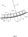
- Fig. 2 illustrates a side view of a curved aircraft substructure repair stiffener in accordance with an example of the disclosure.
- Fig. 2 shows an aircraft repair 200 that includes curved aircraft substructure repair stiffener 210 coupled to fuselage 206.
- the fuselage 206 may be a curved structure of the aircraft 100.
- the curved aircraft substructure repair stiffener 210 includes slits 220A-G to aid in substantially conforming at least a part of the leg portion to the curvature of the fuselage 206.
- the curved aircraft substructure repair stiffener 210 may be used to repair portions of the aircraft 100.
- the curved aircraft substructure repair stiffener 210 may allow repairs that structurally strengthen a damaged area of the aircraft 100.
- a portion of the aircraft 100 may be repaired and/or replaced and the curved aircraft substructure repair stiffener 210 may then be attached to the aircraft 100 (e.g., the repaired portion of the aircraft 100) to structurally strengthen the aircraft 100 (e.g., the repaired portion of the aircraft 100).
- Fig. 2 shows the radius 250.
- the radius 250 may be a radius of the curvature of the fuselage 206.
- At least a portion of the top portion of the curved aircraft substructure repair stiffener 210 may be curved such that at least a part of the leg portion substantially conforms to the radius 250 of the curvature of the fuselage 206.
- at least one of the slits 220A-G may be parallel and/or collinear with the radius 250.
- Fig. 3A illustrates a flat pattern of a Z shaped curved aircraft substructure repair stiffener in accordance with an example of the disclosure.
- Fig. 3A may show the flat pattern 312.
- the flat pattern 312 may be divided into a top portion 314, a side portion 316, and a leg portion 318.
- the leg portion 318 may include a plurality of leg flanges 322A-O and the side portion 316 may include a plurality of side flanges 324A-O.
- Each leg flange may be coupled to a corresponding side flange (e.g., leg flange 322A may be coupled to side flange 324A, leg flange 322B may be coupled to side flange 324B, and so on).
- Each of the leg flange and side flange may be defined, at least in part, by one or more slits 320A-N.
- leg flange 322A and side flange 324A may be defined by, at least, two sides of the flat pattern 312 and the slit 320A
- leg flange 322B and side flange 324B may be defined by, at least, a side of the flat pattern 312 and the slits 320A and 320B.
- Other leg flanges and side flanges may be defined by additional combinations of slits and portions of the flat pattern 312.
- the slits 320A-N may be formed on the flat pattern by, for example, cutting, stamping, laser cutting, machining, or other techniques of forming the slits 320A-N. Additionally, in certain examples, the slits 320A-N may include stress relief features 326A-N.
- the stress relief features 326A-N may be a cutout at the end of the slits 320A-N such as, for example, a circular or other shaped cut.
- the stress relief features 326A-N may be formed along with the slits 320A-N or may be formed as a secondary processing step. The stress relief features 326A-N may aid in preventing further tearing of the slits 326A-N during bending of the flat pattern 312.
- the slits 320A-N may include one or more slots and/or other cutouts. Such slots may augment or replace the slits. In such examples, the slots may also include one or more stress relief features and/or other features that may decrease stress and/or aid in the bending of the curved aircraft substructure repair stiffener.
- Fig. 3B illustrates an isometric view of a Z shaped curved aircraft substructure repair stiffener in accordance with an example of the disclosure.
- Fig. 3B shows a curved aircraft substructure repair stiffener 310.
- the curved aircraft substructure repair stiffener 310 may be manufactured by bending the flat pattern 312 into the shape of the curved aircraft substructure repair stiffener 310.
- the curved aircraft substructure repair stiffener 310 may be a Z shaped repair stiffener.
- the leg portion 318 may include the leg flanges 322A-O and the side portion 316 may include the side flanges 324A-O.
- the curved aircraft substructure repair stiffener 310 may be bent into the Z shape.
- Each individual leg flange 322A-O and side flange 324A-O may not be connected to other individual leg flanges and side flanges.
- leg flange 322A may be coupled to corresponding side flange 324A and side flange 324A may then be coupled to the top portion 314.
- Other leg flanges and side flanges may also be coupled in that manner.
- the top portion 314 may be bent such that the curved aircraft substructure repair stiffener 310 substantially conforms to a curvature of the portion of the aircraft 100 that the curved aircraft substructure repair stiffener 310 is repairing and/or is coupled to.
- substantially conforms may denote that a portion of the leg flanges may contact a portion of the aircraft 100 at some point. Bending of the top portion 314 may then allow for the leg portions 322A-O to substantially conform to the curvature of the portion of the aircraft 100 similar to that shown in Fig. 2 .
- the curved aircraft substructure repair stiffener 310 may be bent according to one radius, but other examples may bend different portions of the curved aircraft substructure repair stiffener 310 according to a plurality of radii or may include a flat (unbent) portion in addition to the bent portion of the curved aircraft substructure repair stiffener 310.
- a web stock 328 may be coupled to a portion of the curved substructure repair stiffener 310 to stiffen the curved substructure repair stiffener 310.
- the web stock 328 may, for example, be trimmed from the same or another piece of stock that is used to form the flat pattern 312.
- the web stock 328 may be formed into a web shape.
- the web stock 328 may be coupled to at least a portion of the leg portion 318 (in such a configuration, the web stock 328 may be known as a leg web), the side portion 316 (in such a configuration, the web stock 328 may be known as a side web), and/or the top portion 314 (in such a configuration, the web stock 328 may be known as a top web).
- the web stock 328 may be coupled to the curved substructure repair stiffener 310 via, for example, fasteners (e.g., nuts, bolts, screws, rivets, and other mechanical fasteners), welding, brazing, features on the curved substructure repair stiffener 310 and/or the web stock 328 (e.g., nuts, springs, and other forms), and/or other fastening techniques.
- fasteners e.g., nuts, bolts, screws, rivets, and other mechanical fasteners
- welding brazing
- features on the curved substructure repair stiffener 310 and/or the web stock 328 e.g., nuts, springs, and other forms
- other fastening techniques e.g., the web stock 328 may be coupled to a side of the side portion 316.
- the web stock 328 may be coupled to another side of the side portion 316 or to another part of the curved substructure repair stiffener 310 (e.g., the top portion 314 and/or the leg portion
- Fig. 4A illustrates a flat pattern of a hat shaped curved aircraft substructure repair stiffener in accordance with an example of the disclosure.
- Fig. 4A may show the flat pattern 412.
- the flat pattern 412 may be divided into a top portion 414, side portions 416A and 416B, and leg portions 418A and 418B.
- the flat pattern 412 of Fig. 4A may be a flat pattern for a hat shaped curved substructure repair stiffener (such as curved substructure repair stiffener 410 shown in Fig. 4B ).
- the leg portions 418A and 418B may include a plurality of leg flanges 422A-O and 430A-O, respectively.
- the side portions 416A and 416B may include a plurality of side flanges 424A-O and 428A-O, respectively.
- Each of the leg flange and side flange may be defined, at least in part, by one or more slits 420A-N or 432 A-N.
- the slits 420A-N and 432A-N may be formed on the flat pattern by, for example, cutting, stamping, laser cutting, machining, or other techniques.
- the slits 420A-N and/or 432A-N may include stress relief features 426A-N and/or 434A-N.
- the stress relief features 426A-N and/or 434A-N may be a cutout at the end of the slits 420A-N and/or 432A-N.
- the slits 420A-N and/or 432A-N may be one or more slots.
- Fig. 4B illustrates an isometric view of a hat shaped curved aircraft substructure repair stiffener in accordance with an example of the disclosure.
- the curved aircraft substructure repair stiffener 410 may be, for example, the curved aircraft substructure repair stiffener 412 bent into the hat shape.
- Each individual leg flange 422A-O and 430A-O and side flange 424A-O and 428A-O may not be connected to other individual leg flanges and side flanges.
- leg flange 422A may be coupled to corresponding side flange 424A and the side flange 424A may then be coupled to the top portion 414.
- Other leg flanges and side flanges may also be coupled in that manner.
- the top portion 414 may be bent such that the curved aircraft substructure repair stiffener 410 substantially conforms to a curvature of the portion of the aircraft 100 that the curved aircraft substructure repair stiffener 410 is repairing and/or is coupled to.
- one or more of web stocks 428A, 428B, 430, and/or 432 may be coupled to portions of the curved substructure repair stiffener 410 to stiffen the curved substructure repair stiffener 410.
- the web stock 428A may be coupled to at least a portion of the side portion 416A
- the web stock 428B may be coupled to at least a portion of the side portion 416B
- the web stock 430 may be coupled to the top portion 414
- the web stock 432 may be coupled to the leg portion 418A and/or 418B. While the examples of Fig.
- FIGS. 4B show the web stocks 428A, 428B, 430, and/or 432 coupled to one side of the portions of the curved substructure repair stiffener 410, other examples may couple the web stocks 428A, 428B, 430, and/or 432 to another side of the portions of the curved substructure repair stiffener 410.
- Figs. 3B and 4B may illustrate Z shaped and hat shaped curved substructure repair stiffeners
- other examples may include curved substructure repair stiffeners in other shapes (e.g., L shaped, M shaped, or other such shapes).
- various examples of the curved substructure repair stiffener may be made from metals (e.g., aluminum, steel, titanium, copper, and/or other metals), composites (e.g., carbon fiber, fiberglass, and/or other composites), wood, and/or other materials.
- Fig. 5 illustrates a sequence of operation of repairing a curved aircraft structure with a curved aircraft substructure repair stiffener in accordance with an example of the disclosure.
- the process described in Fig. 5 may be performed as a factory repair, as a field repair, or as another type of repair.
- a flat pattern may be produced (and provided to a mechanical to be bent by a mechanic repairing the aircraft).
- a curved aircraft substructure repair stiffener may be produced and provided as a field repair kit (e.g., may be produced with bent portions such as side portions and leg portions, but not curved, that may then be curved when coupled to the aircraft or may be produced as a complete curved aircraft substructure repair stiffener matching a curvature of the aircraft before being provided to the mechanic).
- the curved aircraft substructure repair stiffener may be produced as a field repair.
- stock may be trimmed into a flat pattern.
- a piece of sheetmetal or sheet aluminum may be trimmed into a flat pattern that may be configured to be bent into a curved aircraft substructure repair stiffener.
- the flat pattern may be created via a stencil or other tool, but other examples may allow for the flat pattern to be formed freely (e.g., fully or partially formed through free-hand, ruler, or other techniques of cutting by a mechanic).
- slits and/or other openings may be cut in the flat pattern.
- the flat pattern may then be bent in block 506.
- Various portions of the flat pattern may be bent according to the shape of the curved aircraft substructure repair stiffener. As such, for example, a Z-shaped stiffener may be bent at least twice, while a hat-shaped stiffener may be bent at least four times. Other stiffeners in other shapes may be bent a number of different times.
- stiffeners may bend the stock in 90 degree angles or substantially 90 degree angles (e.g., within +/- 5 degrees of 90 degree), but other examples may bend the stock in other angles as needed (e.g., substantially 45 degree angles, substantially 30 degree angles, substantially 60 degree angles, or other angles).
- the curved aircraft substructure repair stiffener may be coupled to the aircraft.
- the curved aircraft substructure repair stiffener may, for example, be coupled to a section of the aircraft to strengthen that section.
- the curved aircraft substructure repair stiffener may be coupled to the aircraft through mechanical fastening, bonding, or another coupling technique.
- web stock may be coupled to the side portion, top portion, leg portion, and/or other portions of the curved aircraft substructure repair stiffener.
- the web stock may be coupled to the curved aircraft substructure repair stiffener after the curved aircraft substructure repair stiffener is coupled to the aircraft, but in certain other examples, the web stock may be coupled to the curved aircraft substructure repair stiffener before the curved aircraft substructure repair stiffener is coupled to the aircraft, during when the curved aircraft substructure repair stiffener is coupled to the aircraft, or after the curved aircraft substructure repair stiffener is coupled to the aircraft.
- the web stock may be coupled via the same fasteners, processes, and/or techniques that couple the curved aircraft substructure repair stiffener to the aircraft and/or different fasteners, processes, and/or techniques.
Landscapes
- Engineering & Computer Science (AREA)
- Aviation & Aerospace Engineering (AREA)
- Mechanical Engineering (AREA)
- Manufacturing & Machinery (AREA)
- Transportation (AREA)
Abstract
Description
- The disclosure relates generally to aircraft and more specifically to repairing curved aircraft structures.
- Aircraft fuselages and other structures may be curved. Repair of curved structures require entire substructures to be replaced with prefabricated spare parts. The spare parts are expensive and must be ordered, resulting in extended downtime for aircrafts being repaired.
- Systems and methods are disclosed herein for a curved aircraft substructure repair stiffener. In certain examples, a method may be disclosed. The method may include trimming a first stock into a blank shape, cutting a plurality of slits into the first stock, bending the first stock at least a plurality of times, where the bent first stock comprises a leg portion configured to be coupled to an aircraft, a side portion coupled to the leg portion, and a top portion coupled to the side portion, and where the leg portion and the side portion include the plurality of slits and the plurality of slits divides the leg portion into a plurality of leg flanges and the side portion into a plurality of side flanges, coupling the leg portion to a curved portion of the aircraft, where the leg portion substantially conforms to a curvature of the curved portion, and fastening the leg portion to the aircraft.
- In a refinement of the method, the leg portion is connected to the side portion at a first angle and the side portion is connected to the top portion at a second angle and the method comprises: and coupling the leg portion to a curve portion of the aircraft, wherein the leg portion substantially conforms to a curvature of the curved portion.
- In certain other examples, an apparatus may be disclosed. The apparatus may include a first stock body including a leg portion including a plurality of leg flanges and configured to couple to and substantially conform to a curvature of a curved portion of an aircraft, a side portion coupled to the leg portion and including a plurality of side flanges, and a top portion coupled to the side portion, where at least a portion of the top portion is curved.
- Further, there is disclosed an aircraft comprising the above apparatus, the aircraft comprising: a fuselage; a wing coupled to the fuselage; and a propulsor coupled to the fuselage and/or the wing, wherein the apparatus is coupled to at least one of the fuselage and/or the wing.
- The scope of the invention is defined by the claims, which are incorporated into this section by reference. A more complete understanding of the disclosure will be afforded to those skilled in the art, as well as a realization of additional advantages thereof, by a consideration of the following detailed description of one or more implementations. Reference will be made to the appended sheets of drawings that will first be described briefly.
-
-
Fig. 1 illustrates a perspective view of an aircraft in accordance with an example of the disclosure. -
Fig. 2 illustrates a side view of a curved aircraft substructure repair stiffener in accordance with an example of the disclosure. -
Fig. 3A illustrates a flat pattern of a Z shaped curved aircraft substructure repair stiffener in accordance with an example of the disclosure. -
Fig. 3B illustrates an isometric view of a Z shaped curved aircraft substructure repair stiffener in accordance with an example of the disclosure. -
Fig. 4A illustrates a flat pattern of a hat shaped curved aircraft substructure repair stiffener in accordance with an example of the disclosure. -
Fig. 4B illustrates an isometric view of a hat shaped curved aircraft substructure repair stiffener in accordance with an example of the disclosure. -
Fig. 5 illustrates a sequence of operation of repairing a curved aircraft structure with a curved aircraft substructure repair stiffener in accordance with an example of the disclosure. - Examples of the disclosure and their advantages are best understood by referring to the detailed description that follows. It should be appreciated that like reference numerals are used to identify like elements illustrated in one or more of the figures.
- Systems and techniques for repairing curved aircraft structures are described in the disclosure herein in accordance with one or more examples. The aircraft structures may be any component of an aircraft such as, for example, the fuselage, aerodynamic devices such as wings, tails, horizontal stabilizers, or other airfoils, aircraft propulsors, and/or other components of the aircraft.
- Such aircraft structures may be curved. Damage may be sustained by such aircraft structures. Conventional aircraft structure field repair techniques are suitable for repairing straight structures, conventional repair techniques for repairing curved structures require entire substructures to be replaced with prefabricated spare parts. The systems and techniques disclosed herein allow for curved aircraft structures to be field repaired.
-
Fig. 1 illustrates a perspective view of an aircraft in accordance with an example of the disclosure. InFig. 1 ,aircraft 100 includes a mainaerodynamic device 102, a secondaryaerodynamic device 104, afuselage 106, and apropulsor 108. Though theaircraft 100 shown inFig. 1 may be a passenger airplane, other examples of theaircraft 100 may include any type of aircraft such as transport planes, helicopters, military aircraft, spacecraft, ground effects vehicles, and other such vehicles. - The
propulsor 108 may be any type of aircraft engine. Non-limiting examples of such engines include turbofans, turboprops, and turbojets. Anaircraft 100 may have any number ofpropulsors 108. Thefuselage 106 may be any type of aircraft fuselage. Thefuselage 106 may be curved and may bear structural loads. For example, thefuselage 106 may bear loads from the structure of theaircraft 100 itself, load carried by theaircraft 100, the mainaerodynamic device 102, secondaryaerodynamic device 104, thepropulsor 108, and/or other components of theaircraft 100. As such, thefuselage 106 may require a certain structural rigidity and repaired sections of thefuselage 106 may be required to maintain such structural rigidity. - The main
aerodynamic device 102 may be any fixed portion of a component of theaircraft 100 that may directly or indirectly affect the handling of theaircraft 100. As such, non-limiting examples of the mainaerodynamic device 102 may include a wing, as shown inFig. 1 , a tail, a horizontal stabilizer, and another such control surface. For the purposes of this disclosure, any component that may generate lift, drag, steering force, and/or other such aerodynamic forces may be considered an aerodynamic device. InFig. 1 , the mainaerodynamic device 102 may be fixed to thefuselage 106 of theaircraft 100, but other examples may fix the mainaerodynamic device 102 to other portions of theaircraft 100. - The secondary
aerodynamic device 104 may move relative to the mainaerodynamic device 102. As such, the secondaryaerodynamic device 104 may be a slat, a flap, a droop nose, an aileron, a flaperon, an elevator, a rudder, a moveable spoiler, portions of a flexible wing, or another such moveable aerodynamic component. ThoughFig. 1 shows an example of anaircraft 100 with five secondaryaerodynamic devices 104 per mainaerodynamic device 102, other examples of theaircraft 100 may include any number of secondaryaerodynamic devices 104 per mainaerodynamic device 102. -
Fig. 2 illustrates a side view of a curved aircraft substructure repair stiffener in accordance with an example of the disclosure.Fig. 2 shows anaircraft repair 200 that includes curved aircraftsubstructure repair stiffener 210 coupled tofuselage 206. Thefuselage 206 may be a curved structure of theaircraft 100. The curved aircraftsubstructure repair stiffener 210 includesslits 220A-G to aid in substantially conforming at least a part of the leg portion to the curvature of thefuselage 206. - In certain examples, the curved aircraft
substructure repair stiffener 210 may be used to repair portions of theaircraft 100. The curved aircraftsubstructure repair stiffener 210 may allow repairs that structurally strengthen a damaged area of theaircraft 100. In certain examples, a portion of theaircraft 100 may be repaired and/or replaced and the curved aircraftsubstructure repair stiffener 210 may then be attached to the aircraft 100 (e.g., the repaired portion of the aircraft 100) to structurally strengthen the aircraft 100 (e.g., the repaired portion of the aircraft 100). - Additionally,
Fig. 2 shows theradius 250. Theradius 250 may be a radius of the curvature of thefuselage 206. At least a portion of the top portion of the curved aircraftsubstructure repair stiffener 210 may be curved such that at least a part of the leg portion substantially conforms to theradius 250 of the curvature of thefuselage 206. Additionally, at least one of theslits 220A-G may be parallel and/or collinear with theradius 250. -
Fig. 3A illustrates a flat pattern of a Z shaped curved aircraft substructure repair stiffener in accordance with an example of the disclosure.Fig. 3A may show theflat pattern 312. Theflat pattern 312 may be divided into atop portion 314, aside portion 316, and aleg portion 318. Theleg portion 318 may include a plurality ofleg flanges 322A-O and theside portion 316 may include a plurality ofside flanges 324A-O. Each leg flange may be coupled to a corresponding side flange (e.g.,leg flange 322A may be coupled toside flange 324A, leg flange 322B may be coupled to side flange 324B, and so on). Each of the leg flange and side flange may be defined, at least in part, by one ormore slits 320A-N. As such,leg flange 322A andside flange 324A may be defined by, at least, two sides of theflat pattern 312 and theslit 320A, leg flange 322B and side flange 324B may be defined by, at least, a side of theflat pattern 312 and theslits 320A and 320B. Other leg flanges and side flanges may be defined by additional combinations of slits and portions of theflat pattern 312. - The
slits 320A-N may be formed on the flat pattern by, for example, cutting, stamping, laser cutting, machining, or other techniques of forming theslits 320A-N. Additionally, in certain examples, theslits 320A-N may include stress relief features 326A-N. The stress relief features 326A-N may be a cutout at the end of theslits 320A-N such as, for example, a circular or other shaped cut. The stress relief features 326A-N may be formed along with theslits 320A-N or may be formed as a secondary processing step. The stress relief features 326A-N may aid in preventing further tearing of theslits 326A-N during bending of theflat pattern 312. - In certain examples, the
slits 320A-N may include one or more slots and/or other cutouts. Such slots may augment or replace the slits. In such examples, the slots may also include one or more stress relief features and/or other features that may decrease stress and/or aid in the bending of the curved aircraft substructure repair stiffener. -
Fig. 3B illustrates an isometric view of a Z shaped curved aircraft substructure repair stiffener in accordance with an example of the disclosure.Fig. 3B shows a curved aircraftsubstructure repair stiffener 310. The curved aircraftsubstructure repair stiffener 310 may be manufactured by bending theflat pattern 312 into the shape of the curved aircraftsubstructure repair stiffener 310. The curved aircraftsubstructure repair stiffener 310 may be a Z shaped repair stiffener. - In
Fig. 3B , theleg portion 318 may include theleg flanges 322A-O and theside portion 316 may include theside flanges 324A-O. The curved aircraftsubstructure repair stiffener 310 may be bent into the Z shape. Eachindividual leg flange 322A-O andside flange 324A-O may not be connected to other individual leg flanges and side flanges. However,leg flange 322A may be coupled to correspondingside flange 324A andside flange 324A may then be coupled to thetop portion 314. Other leg flanges and side flanges may also be coupled in that manner. - The
top portion 314 may be bent such that the curved aircraftsubstructure repair stiffener 310 substantially conforms to a curvature of the portion of theaircraft 100 that the curved aircraftsubstructure repair stiffener 310 is repairing and/or is coupled to. For the purposes of this disclosure, "substantially conforms" may denote that a portion of the leg flanges may contact a portion of theaircraft 100 at some point. Bending of thetop portion 314 may then allow for theleg portions 322A-O to substantially conform to the curvature of the portion of theaircraft 100 similar to that shown inFig. 2 . In certain examples, the curved aircraftsubstructure repair stiffener 310 may be bent according to one radius, but other examples may bend different portions of the curved aircraftsubstructure repair stiffener 310 according to a plurality of radii or may include a flat (unbent) portion in addition to the bent portion of the curved aircraftsubstructure repair stiffener 310. - In certain examples, a
web stock 328 may be coupled to a portion of the curvedsubstructure repair stiffener 310 to stiffen the curvedsubstructure repair stiffener 310. Theweb stock 328 may, for example, be trimmed from the same or another piece of stock that is used to form theflat pattern 312. Theweb stock 328 may be formed into a web shape. Theweb stock 328 may be coupled to at least a portion of the leg portion 318 (in such a configuration, theweb stock 328 may be known as a leg web), the side portion 316 (in such a configuration, theweb stock 328 may be known as a side web), and/or the top portion 314 (in such a configuration, theweb stock 328 may be known as a top web). Theweb stock 328 may be coupled to the curvedsubstructure repair stiffener 310 via, for example, fasteners (e.g., nuts, bolts, screws, rivets, and other mechanical fasteners), welding, brazing, features on the curvedsubstructure repair stiffener 310 and/or the web stock 328 (e.g., nuts, springs, and other forms), and/or other fastening techniques. In the example shown inFig. 2 , theweb stock 328 may be coupled to a side of theside portion 316. In other examples, theweb stock 328 may be coupled to another side of theside portion 316 or to another part of the curved substructure repair stiffener 310 (e.g., thetop portion 314 and/or the leg portion 318). -
Fig. 4A illustrates a flat pattern of a hat shaped curved aircraft substructure repair stiffener in accordance with an example of the disclosure.Fig. 4A may show theflat pattern 412. Theflat pattern 412 may be divided into atop portion 414,side portions leg portions flat pattern 412 ofFig. 4A may be a flat pattern for a hat shaped curved substructure repair stiffener (such as curvedsubstructure repair stiffener 410 shown inFig. 4B ). - The
leg portions leg flanges 422A-O and 430A-O, respectively. Theside portions side flanges 424A-O and 428A-O, respectively. Each of the leg flange and side flange may be defined, at least in part, by one ormore slits 420A-N or 432 A-N. - The
slits 420A-N and 432A-N may be formed on the flat pattern by, for example, cutting, stamping, laser cutting, machining, or other techniques. In certain examples, theslits 420A-N and/or 432A-N may include stress relief features 426A-N and/or 434A-N. The stress relief features 426A-N and/or 434A-N may be a cutout at the end of theslits 420A-N and/or 432A-N. In certain examples, theslits 420A-N and/or 432A-N may be one or more slots. -
Fig. 4B illustrates an isometric view of a hat shaped curved aircraft substructure repair stiffener in accordance with an example of the disclosure. The curved aircraftsubstructure repair stiffener 410 may be, for example, the curved aircraftsubstructure repair stiffener 412 bent into the hat shape. Eachindividual leg flange 422A-O and 430A-O andside flange 424A-O and 428A-O may not be connected to other individual leg flanges and side flanges. However,leg flange 422A may be coupled to correspondingside flange 424A and theside flange 424A may then be coupled to thetop portion 414. Other leg flanges and side flanges may also be coupled in that manner. - The
top portion 414 may be bent such that the curved aircraftsubstructure repair stiffener 410 substantially conforms to a curvature of the portion of theaircraft 100 that the curved aircraftsubstructure repair stiffener 410 is repairing and/or is coupled to. - In certain examples, one or more of
web stocks substructure repair stiffener 410 to stiffen the curvedsubstructure repair stiffener 410. For example, theweb stock 428A may be coupled to at least a portion of theside portion 416A, theweb stock 428B may be coupled to at least a portion of theside portion 416B, theweb stock 430 may be coupled to thetop portion 414, and theweb stock 432 may be coupled to theleg portion 418A and/or 418B. While the examples ofFig. 4B show theweb stocks substructure repair stiffener 410, other examples may couple theweb stocks substructure repair stiffener 410. - While
Figs. 3B and4B may illustrate Z shaped and hat shaped curved substructure repair stiffeners, other examples may include curved substructure repair stiffeners in other shapes (e.g., L shaped, M shaped, or other such shapes). Additionally, various examples of the curved substructure repair stiffener may be made from metals (e.g., aluminum, steel, titanium, copper, and/or other metals), composites (e.g., carbon fiber, fiberglass, and/or other composites), wood, and/or other materials. -
Fig. 5 illustrates a sequence of operation of repairing a curved aircraft structure with a curved aircraft substructure repair stiffener in accordance with an example of the disclosure. The process described inFig. 5 may be performed as a factory repair, as a field repair, or as another type of repair. In certain examples, a flat pattern may be produced (and provided to a mechanical to be bent by a mechanic repairing the aircraft). In certain other examples, a curved aircraft substructure repair stiffener may be produced and provided as a field repair kit (e.g., may be produced with bent portions such as side portions and leg portions, but not curved, that may then be curved when coupled to the aircraft or may be produced as a complete curved aircraft substructure repair stiffener matching a curvature of the aircraft before being provided to the mechanic). In other examples, the curved aircraft substructure repair stiffener may be produced as a field repair. - In
block 502, stock may be trimmed into a flat pattern. For example, a piece of sheetmetal or sheet aluminum may be trimmed into a flat pattern that may be configured to be bent into a curved aircraft substructure repair stiffener. In certain examples, the flat pattern may be created via a stencil or other tool, but other examples may allow for the flat pattern to be formed freely (e.g., fully or partially formed through free-hand, ruler, or other techniques of cutting by a mechanic). - In
block 504, slits and/or other openings (e.g., slots) may be cut in the flat pattern. The flat pattern may then be bent inblock 506. Various portions of the flat pattern may be bent according to the shape of the curved aircraft substructure repair stiffener. As such, for example, a Z-shaped stiffener may be bent at least twice, while a hat-shaped stiffener may be bent at least four times. Other stiffeners in other shapes may be bent a number of different times. Certain examples of stiffeners may bend the stock in 90 degree angles or substantially 90 degree angles (e.g., within +/- 5 degrees of 90 degree), but other examples may bend the stock in other angles as needed (e.g., substantially 45 degree angles, substantially 30 degree angles, substantially 60 degree angles, or other angles). - In
block 508, the curved aircraft substructure repair stiffener may be coupled to the aircraft. The curved aircraft substructure repair stiffener may, for example, be coupled to a section of the aircraft to strengthen that section. The curved aircraft substructure repair stiffener may be coupled to the aircraft through mechanical fastening, bonding, or another coupling technique. - In
block 510, web stock may be coupled to the side portion, top portion, leg portion, and/or other portions of the curved aircraft substructure repair stiffener. In the embodiment shown inFig. 5 , the web stock may be coupled to the curved aircraft substructure repair stiffener after the curved aircraft substructure repair stiffener is coupled to the aircraft, but in certain other examples, the web stock may be coupled to the curved aircraft substructure repair stiffener before the curved aircraft substructure repair stiffener is coupled to the aircraft, during when the curved aircraft substructure repair stiffener is coupled to the aircraft, or after the curved aircraft substructure repair stiffener is coupled to the aircraft. The web stock may be coupled via the same fasteners, processes, and/or techniques that couple the curved aircraft substructure repair stiffener to the aircraft and/or different fasteners, processes, and/or techniques. - Further, the current disclosure comprises embodiments according to the following clauses:
- Clause 1. A method comprising:
- trimming a first stock into a blank shape; and
- cutting a plurality of slits into the first stock, wherein the first stock is configured to be bent at least a plurality of times to form a leg portion configured to be coupled to an aircraft, a side portion connection to the leg portion, and a top portion connected to the side portion, wherein the leg portion and the side portion include the plurality of slits and the plurality of slits divides the leg portion into a plurality of leg flanges and the side portion into a plurality of side flanges, wherein the bent first stock is configured to be coupled to the aircraft to reinforce at least a portion of the aircraft.
- Clause 2. The method of clause 1, further comprising:
- bending the first stock at least the plurality of times to form the leg portion, the side portion, and the top portion.
- Clause 3. The method of clause 1 or 2, wherein bending the first stock comprises:
- bending the first stock to form the leg portion, the side portion, and the top portion; and
- bending at least a portion of the top portion along a curve such that the leg portion substantially conforms to a curvature of a curved portion.
- Clause 4. The method of any of clauses 1 to 3, further comprising:
- coupling the leg portion to a curved portion of the aircraft, wherein the leg portion substantially conforms to a curvature of the curved portion and the coupling comprises fastening the leg portion to the aircraft.
- Clause 5. The method of any of clauses 1 to 4, further comprising:
- trimming a second stock into a web shape; and
- coupling the second stock to at least a plurality of the side flanges.
- Clause 6. The method of any of clauses 1 to 5, wherein the first stock is bent into a Z shape.
- Clause 7. The method of clause 6, further comprising:
- trimming a second stock into a first web shape;
- coupling the second stock to a first side of the side portion, wherein coupling the second stock comprises coupling the second stock to at least a plurality of the side flanges;
- trimming a third stock into a second web shape; and
- coupling the third stock to a second side of the side portion, wherein coupling the third stock comprises coupling the third stock to at least a plurality of the side flanges.
- Clause 8. The method of any of clauses 1 to 7, wherein the first stock is bent into a hat shape.
- Clause 9. The method of clause 8, wherein the hat shape comprises a first side portion comprising a plurality of first side flanges and a second side portion comprising a plurality of second side flanges, and the method further comprises:
- trimming a second stock into a first web shape;
- coupling the second stock to at least a plurality of the first side flanges;
- trimming a third stock into a second web shape; and
- coupling the third stock to at least a plurality of the second side flanges.
- Clause 10. The method of any of clauses 1 to 9, further comprising:
- coupling a leg web to at least a plurality of leg flanges; and
- coupling a top web to the top portion.
- Clause 11. The method of any of clauses 1 to 10, further comprising:
- forming a stress relief feature on at least an end of each of the plurality of slits.
- Clause 12. An apparatus comprising:
- a first stock body comprising:
- a leg portion comprising a plurality of leg flanges and configured to couple to and substantially conform to a curvature of a curved portion of an aircraft;
- a side portion connected to the leg portion and comprising a plurality of side flanges; and
- a top portion connected to the side portion, wherein at least a portion of the top portion is configured to be curved upon the leg portion substantially conforming to the curvature of the curved portion of the aircraft and the first stock body is configured to be bent and coupled to the aircraft to reinforce at least a portion of the aircraft.
- a first stock body comprising:
- Clause 13. The apparatus of clause 12, further comprising:
- a web stock coupled to at least a plurality of the side flanges.
- Clause 14. The apparatus of clause 12 or 13, wherein the first stock body is bent into a Z shape, the Z shape comprises at least the leg portion connected to the side portion at a first angle and the side portion connected to the top portion at a second angle.
- Clause 15. The apparatus of clause 14, wherein the first angle and the second angle are the same angle and/or are angles between 85-95 degrees.
- Clause 16. The apparatus of any of clauses 12 to 15, wherein the first stock body is bent into a hat shape, the side portion is a first side portion comprising a plurality of first side flanges and the leg portion is a first leg portion, and further comprising:
- a second side portion comprising a plurality of second side flanges and connected to the top portion; and
- a second leg portion connected to the second side portion and configured to couple to and substantially conform to a curvature of a curved portion of an aircraft, wherein the hat shape comprises at least the first leg portion connected to the first side portion at a first angle, the first side portion connected to the top portion at a second angle, the top portion connected to the second side portion at a third angle, and the second side portion connected to the second leg portion at a fourth angle.
- Clause 17. The apparatus of any of clauses 12 to 16, further comprising a leg web coupled to at least a plurality of the leg flanges and a top web coupled to the top portion.
- Clause 18. The apparatus of any of clauses 12 to 17, wherein the plurality of leg flanges and the plurality of side flanges are formed via a plurality of slits and further comprising a stress relief feature on at least an end of each of the plurality of slits.
- Clause 19. A method of aircraft fuselage repair using the apparatus of any of clauses 12 to 18, wherein the leg portion connected to the side portion at a first angle and the side portion is connected to the top portion at a second angle and the method comprises: and
coupling the leg portion to a curve portion of the aircraft, wherein the leg portion substantially conforms to a curvature of the curved portion. - Clause 20. An aircraft comprising the apparatus of any of clauses 12 to 18, the aircraft comprising:
- a fuselage;
- a wing coupled to the fuselage; and
- a propulsor coupled to the fuselage and/or the wing, wherein the apparatus is coupled to at least one of the fuselage and/or the wing.
- Examples described above illustrate but do not limit the invention. It should also be understood that numerous modifications and variations are possible in accordance with the principles of the present invention. Accordingly, the scope of the invention is defined only by the following claims.
Claims (15)
- A method comprising:trimming (502) a first stock into a blank shape; andcutting (504) a plurality of slits into the first stock, wherein the first stock is configured to be bent at least a plurality of times to form a leg portion configured to be coupled to an aircraft, a side portion connection to the leg portion, and a top portion connected to the side portion, wherein the leg portion and the side portion include the plurality of slits and the plurality of slits divides the leg portion into a plurality of leg flanges and the side portion into a plurality of side flanges, wherein the bent first stock is configured to be coupled to the aircraft to reinforce at least a portion of the aircraft.
- The method of claim 1, further comprising:bending (506) the first stock at least the plurality of times to form the leg portion, the side portion, and the top portion.
- The method of claim 2, wherein bending (506) the first stock comprises:bending the first stock to form the leg portion, the side portion, and the top portion; andbending at least a portion of the top portion along a curve such that the leg portion substantially conforms to a curvature of a curved portion.
- The method of any of claims 1 to 3, further comprising:coupling (508) the leg portion to a curved portion of the aircraft, wherein the leg portion substantially conforms to a curvature of the curved portion and the coupling comprises fastening the leg portion to the aircraft.
- The method of any of claims 1 to 4, further comprising:trimming a second stock into a web shape; andcoupling the second stock to at least a plurality of the side flanges.
- The method of any of claims 1 to 5, wherein the first stock is bent into a Z shape, optionally further comprising;
trimming a second stock into a first web shape;
coupling the second stock to a first side of the side portion, wherein coupling the second stock comprises coupling the second stock to at least a plurality of the side flanges;
trimming a third stock into a second web shape; and
coupling the third stock to a second side of the side portion, wherein coupling the third stock comprises coupling the third stock to at least a plurality of the side flanges. - The method of any of claims 1 to 6, wherein the first stock is bent into a hat shape, optionally;
wherein the hat shape comprises a first side portion comprising a plurality of first side flanges and a second side portion comprising a plurality of second side flanges, and the method further comprises:trimming a second stock into a first web shape;coupling the second stock to at least a plurality of the first side flanges;trimming a third stock into a second web shape; andcoupling the third stock to at least a plurality of the second side flanges. - The method of any of claims 1 to 7, further comprising:coupling (510) a leg web to at least a plurality of leg flanges; andcoupling a top web to the top portion.
- The method of any preceding claim, further comprising:forming a stress relief feature on at least an end of each of the plurality of slits.
- An apparatus comprising:a first stock body comprising:a leg portion (318, 418) comprising a plurality of leg flanges and configured to couple to and substantially conform to a curvature of a curved portion of an aircraft;a side portion (316, 416) connected to the leg portion and comprising a plurality of side flanges; anda top portion (314, 414) connected to the side portion, wherein at least a portion of the top portion is configured to be curved upon the leg portion substantially conforming to the curvature of the curved portion of the aircraft and the first stock body is configured to be bent and coupled to the aircraft to reinforce at least a portion of the aircraft.
- The apparatus of claim 10, further comprising:a web stock (328, 428) coupled to at least a plurality of the side flanges.
- The apparatus of claim 10 or 11, wherein the first stock body is bent into a Z shape, the Z shape comprises at least the leg portion connected to the side portion at a first angle and the side portion connected to the top portion at a second angle.
- The apparatus of any of claims 10 to 12, wherein the first stock body (428) is bent into a hat shape, the side portion is a first side portion (416A) comprising a plurality of first side flanges (424A-O) and the leg portion is a first leg portion (418A), and further comprising:a second side portion (416B) comprising a plurality of second side flanges (428A-O) and connected to the top portion; anda second leg portion (418B) connected to the second side portion and configured to couple to and substantially conform to a curvature of a curved portion of an aircraft, wherein the hat shape comprises at least the first leg portion connected to the first side portion at a first angle, the first side portion connected to the top portion at a second angle, the top portion connected to the second side portion at a third angle, and the second side portion connected to the second leg portion at a fourth angle.
- The apparatus of any of claims 10 to 13, further comprising a leg web coupled to at least a plurality of the leg flanges and a top web coupled to the top portion.
- The apparatus of any of claims 10 to 14, wherein the plurality of leg flanges and the plurality of side flanges are formed via a plurality of slits and further comprising a stress relief feature on at least an end of each of the plurality of slits.
Applications Claiming Priority (1)
| Application Number | Priority Date | Filing Date | Title |
|---|---|---|---|
| US15/224,349 US10392132B2 (en) | 2016-07-29 | 2016-07-29 | Curved aircraft substructure repair systems and methods |
Publications (2)
| Publication Number | Publication Date |
|---|---|
| EP3275778A1 true EP3275778A1 (en) | 2018-01-31 |
| EP3275778B1 EP3275778B1 (en) | 2019-08-21 |
Family
ID=58638726
Family Applications (1)
| Application Number | Title | Priority Date | Filing Date |
|---|---|---|---|
| EP17168285.9A Active EP3275778B1 (en) | 2016-07-29 | 2017-04-26 | Curved aircraft substructure repairs systems and methods |
Country Status (2)
| Country | Link |
|---|---|
| US (1) | US10392132B2 (en) |
| EP (1) | EP3275778B1 (en) |
Families Citing this family (2)
| Publication number | Priority date | Publication date | Assignee | Title |
|---|---|---|---|---|
| US10671047B2 (en) * | 2018-03-15 | 2020-06-02 | The Boeing Company | Composite structure repair system and method |
| US20200254702A1 (en) | 2019-02-07 | 2020-08-13 | The Boeing Company | Apparatus and method to tailor fiber distortion in composite parts |
Citations (7)
| Publication number | Priority date | Publication date | Assignee | Title |
|---|---|---|---|---|
| GB665850A (en) * | 1948-10-23 | 1952-01-30 | Boulton Aircraft Ltd | Improvements in and relating to panel structures |
| EP0728541A1 (en) * | 1995-02-24 | 1996-08-28 | Japan Aircraft Mfg. Co., Ltd | Metal sandwich structural body and manufacture thereof |
| WO2002098733A1 (en) * | 2001-06-05 | 2002-12-12 | Saab Ab | Device for bracing a shell in an aircraft fuselage |
| FR2923800A1 (en) * | 2007-11-16 | 2009-05-22 | Airbus France Sas | Connection device i.e. clip device, for e.g. frame, of aircraft, has element with weakened compression zone to absorb impacts subjected by external surface of fuselage skin and another element resisting to forces on internal surface of skin |
| US20120153082A1 (en) * | 2010-12-15 | 2012-06-21 | The Boeing Company | Splice and associated method for joining fuselage sections |
| WO2013093323A1 (en) * | 2011-12-21 | 2013-06-27 | Airbus Operations | Structural element for an aircraft fuselage that prevents lateral-torsional buckling |
| EP3162544A1 (en) * | 2015-10-06 | 2017-05-03 | The Boeing Company | Method and device for producing contoured composite laminate stiffeners with reduced wrinkling |
Family Cites Families (10)
| Publication number | Priority date | Publication date | Assignee | Title |
|---|---|---|---|---|
| US4410370A (en) * | 1979-09-29 | 1983-10-18 | Sumitomo Light Metal Industries, Ltd. | Aircraft stringer material and method for producing the same |
| US7159822B2 (en) * | 2004-04-06 | 2007-01-09 | The Boeing Company | Structural panels for use in aircraft fuselages and other structures |
| US7850387B2 (en) * | 2005-01-06 | 2010-12-14 | The Boeing Company | System for reducing stress concentrations in lap joints |
| EP2015889B1 (en) * | 2006-05-11 | 2014-07-09 | Bell Helicopter Textron Inc. | Device and method for repairing structural components |
| DE102006045633B4 (en) * | 2006-09-27 | 2008-10-23 | Airbus Deutschland Gmbh | Method for connecting a stringer to a structural component of an aircraft or spacecraft |
| DE102007044386A1 (en) * | 2007-09-18 | 2009-04-02 | Airbus Deutschland Gmbh | Structural component and method for stiffening an outer skin |
| FR2953812B1 (en) * | 2009-12-11 | 2012-09-07 | Airbus Operations Sas | PROCESS FOR REPAIRING AN AIRCRAFT FUSELAGE |
| US8844108B2 (en) | 2011-07-12 | 2014-09-30 | The Boeing Company | Large area repair of composite aircraft |
| JP5811082B2 (en) * | 2012-12-19 | 2015-11-11 | 横浜ゴム株式会社 | Connection structure for aircraft interior panels |
| EP2907743A1 (en) * | 2014-02-13 | 2015-08-19 | Airbus Operations GmbH | Stiffening element, method for coupling the same, and shell component for an aircraft or spacecraft |
-
2016
- 2016-07-29 US US15/224,349 patent/US10392132B2/en not_active Expired - Fee Related
-
2017
- 2017-04-26 EP EP17168285.9A patent/EP3275778B1/en active Active
Patent Citations (7)
| Publication number | Priority date | Publication date | Assignee | Title |
|---|---|---|---|---|
| GB665850A (en) * | 1948-10-23 | 1952-01-30 | Boulton Aircraft Ltd | Improvements in and relating to panel structures |
| EP0728541A1 (en) * | 1995-02-24 | 1996-08-28 | Japan Aircraft Mfg. Co., Ltd | Metal sandwich structural body and manufacture thereof |
| WO2002098733A1 (en) * | 2001-06-05 | 2002-12-12 | Saab Ab | Device for bracing a shell in an aircraft fuselage |
| FR2923800A1 (en) * | 2007-11-16 | 2009-05-22 | Airbus France Sas | Connection device i.e. clip device, for e.g. frame, of aircraft, has element with weakened compression zone to absorb impacts subjected by external surface of fuselage skin and another element resisting to forces on internal surface of skin |
| US20120153082A1 (en) * | 2010-12-15 | 2012-06-21 | The Boeing Company | Splice and associated method for joining fuselage sections |
| WO2013093323A1 (en) * | 2011-12-21 | 2013-06-27 | Airbus Operations | Structural element for an aircraft fuselage that prevents lateral-torsional buckling |
| EP3162544A1 (en) * | 2015-10-06 | 2017-05-03 | The Boeing Company | Method and device for producing contoured composite laminate stiffeners with reduced wrinkling |
Also Published As
| Publication number | Publication date |
|---|---|
| US10392132B2 (en) | 2019-08-27 |
| EP3275778B1 (en) | 2019-08-21 |
| US20180029725A1 (en) | 2018-02-01 |
Similar Documents
| Publication | Publication Date | Title |
|---|---|---|
| US11242129B2 (en) | Aerofoil structure and method of assembly | |
| CN106335629B (en) | Fuselage spar structure with continuous integral fastened upper and lower chord sections | |
| US6116539A (en) | Aeroelastically stable forward swept wing | |
| JP4990177B2 (en) | Airplane wing structure | |
| EP2735504B1 (en) | Method of manufacturing a highly integrated structure including leading and trailing edge ribs for an aircraft lifting surface | |
| JP6542508B2 (en) | Continuously curved girder and method of manufacture | |
| EP3415415B1 (en) | A spar arrangement in a wing tip device | |
| CN110603192B (en) | Aircraft Wing-to-Fuselage Interface Allowing Position Adjustment | |
| JP6930876B2 (en) | Aircraft wing and aircraft including the aircraft wing | |
| US7931233B2 (en) | Protective skin for aircraft | |
| US20160244155A1 (en) | Helicopter skid landing gear | |
| EP3415414B1 (en) | Wing-to-fuselage joints and aircraft including the same | |
| EP3898409B1 (en) | Aircraft assembly having an integral spar-cover | |
| EP3275778B1 (en) | Curved aircraft substructure repairs systems and methods | |
| US20190016434A1 (en) | Low stress stiffener runout in pi bonded structure | |
| EP2698241B1 (en) | Highly integrated inner structure of a torsion box of an aircraft lifting surface and method of producing it | |
| CN110582444B (en) | Aircraft wing unit with upper wing skin defining pressure floor | |
| EP3619110B1 (en) | Aircraft wing unit with pressure fence | |
| EP2886450B1 (en) | Aircraft control surface | |
| US4162777A (en) | Canted spar with intermediate intercostal stiffeners | |
| JP7656441B2 (en) | Structural composite airfoil with directly bonded forward spar and related methods | |
| US7677496B2 (en) | Stringer for an aircraft wing and a method of reinforcing thereof | |
| US20190210707A1 (en) | Aircraft panel and method of constructing | |
| EP3241742B1 (en) | Aircraft empennage | |
| US20240174344A1 (en) | Flow body for an aircraft with split ribs |
Legal Events
| Date | Code | Title | Description |
|---|---|---|---|
| PUAI | Public reference made under article 153(3) epc to a published international application that has entered the european phase |
Free format text: ORIGINAL CODE: 0009012 |
|
| STAA | Information on the status of an ep patent application or granted ep patent |
Free format text: STATUS: REQUEST FOR EXAMINATION WAS MADE |
|
| 17P | Request for examination filed |
Effective date: 20170426 |
|
| AK | Designated contracting states |
Kind code of ref document: A1 Designated state(s): AL AT BE BG CH CY CZ DE DK EE ES FI FR GB GR HR HU IE IS IT LI LT LU LV MC MK MT NL NO PL PT RO RS SE SI SK SM TR |
|
| AX | Request for extension of the european patent |
Extension state: BA ME |
|
| GRAP | Despatch of communication of intention to grant a patent |
Free format text: ORIGINAL CODE: EPIDOSNIGR1 |
|
| STAA | Information on the status of an ep patent application or granted ep patent |
Free format text: STATUS: GRANT OF PATENT IS INTENDED |
|
| INTG | Intention to grant announced |
Effective date: 20181002 |
|
| GRAJ | Information related to disapproval of communication of intention to grant by the applicant or resumption of examination proceedings by the epo deleted |
Free format text: ORIGINAL CODE: EPIDOSDIGR1 |
|
| STAA | Information on the status of an ep patent application or granted ep patent |
Free format text: STATUS: REQUEST FOR EXAMINATION WAS MADE |
|
| GRAP | Despatch of communication of intention to grant a patent |
Free format text: ORIGINAL CODE: EPIDOSNIGR1 |
|
| STAA | Information on the status of an ep patent application or granted ep patent |
Free format text: STATUS: GRANT OF PATENT IS INTENDED |
|
| INTC | Intention to grant announced (deleted) | ||
| INTG | Intention to grant announced |
Effective date: 20190228 |
|
| GRAS | Grant fee paid |
Free format text: ORIGINAL CODE: EPIDOSNIGR3 |
|
| GRAA | (expected) grant |
Free format text: ORIGINAL CODE: 0009210 |
|
| STAA | Information on the status of an ep patent application or granted ep patent |
Free format text: STATUS: THE PATENT HAS BEEN GRANTED |
|
| AK | Designated contracting states |
Kind code of ref document: B1 Designated state(s): AL AT BE BG CH CY CZ DE DK EE ES FI FR GB GR HR HU IE IS IT LI LT LU LV MC MK MT NL NO PL PT RO RS SE SI SK SM TR |
|
| REG | Reference to a national code |
Ref country code: GB Ref legal event code: FG4D |
|
| REG | Reference to a national code |
Ref country code: CH Ref legal event code: EP |
|
| REG | Reference to a national code |
Ref country code: DE Ref legal event code: R096 Ref document number: 602017006251 Country of ref document: DE |
|
| REG | Reference to a national code |
Ref country code: AT Ref legal event code: REF Ref document number: 1169448 Country of ref document: AT Kind code of ref document: T Effective date: 20190915 |
|
| REG | Reference to a national code |
Ref country code: IE Ref legal event code: FG4D |
|
| REG | Reference to a national code |
Ref country code: LT Ref legal event code: MG4D |
|
| REG | Reference to a national code |
Ref country code: NL Ref legal event code: MP Effective date: 20190821 |
|
| PG25 | Lapsed in a contracting state [announced via postgrant information from national office to epo] |
Ref country code: LT Free format text: LAPSE BECAUSE OF FAILURE TO SUBMIT A TRANSLATION OF THE DESCRIPTION OR TO PAY THE FEE WITHIN THE PRESCRIBED TIME-LIMIT Effective date: 20190821 Ref country code: HR Free format text: LAPSE BECAUSE OF FAILURE TO SUBMIT A TRANSLATION OF THE DESCRIPTION OR TO PAY THE FEE WITHIN THE PRESCRIBED TIME-LIMIT Effective date: 20190821 Ref country code: NO Free format text: LAPSE BECAUSE OF FAILURE TO SUBMIT A TRANSLATION OF THE DESCRIPTION OR TO PAY THE FEE WITHIN THE PRESCRIBED TIME-LIMIT Effective date: 20191121 Ref country code: SE Free format text: LAPSE BECAUSE OF FAILURE TO SUBMIT A TRANSLATION OF THE DESCRIPTION OR TO PAY THE FEE WITHIN THE PRESCRIBED TIME-LIMIT Effective date: 20190821 Ref country code: FI Free format text: LAPSE BECAUSE OF FAILURE TO SUBMIT A TRANSLATION OF THE DESCRIPTION OR TO PAY THE FEE WITHIN THE PRESCRIBED TIME-LIMIT Effective date: 20190821 Ref country code: PT Free format text: LAPSE BECAUSE OF FAILURE TO SUBMIT A TRANSLATION OF THE DESCRIPTION OR TO PAY THE FEE WITHIN THE PRESCRIBED TIME-LIMIT Effective date: 20191223 Ref country code: BG Free format text: LAPSE BECAUSE OF FAILURE TO SUBMIT A TRANSLATION OF THE DESCRIPTION OR TO PAY THE FEE WITHIN THE PRESCRIBED TIME-LIMIT Effective date: 20191121 Ref country code: NL Free format text: LAPSE BECAUSE OF FAILURE TO SUBMIT A TRANSLATION OF THE DESCRIPTION OR TO PAY THE FEE WITHIN THE PRESCRIBED TIME-LIMIT Effective date: 20190821 |
|
| PG25 | Lapsed in a contracting state [announced via postgrant information from national office to epo] |
Ref country code: IS Free format text: LAPSE BECAUSE OF FAILURE TO SUBMIT A TRANSLATION OF THE DESCRIPTION OR TO PAY THE FEE WITHIN THE PRESCRIBED TIME-LIMIT Effective date: 20191221 Ref country code: RS Free format text: LAPSE BECAUSE OF FAILURE TO SUBMIT A TRANSLATION OF THE DESCRIPTION OR TO PAY THE FEE WITHIN THE PRESCRIBED TIME-LIMIT Effective date: 20190821 Ref country code: LV Free format text: LAPSE BECAUSE OF FAILURE TO SUBMIT A TRANSLATION OF THE DESCRIPTION OR TO PAY THE FEE WITHIN THE PRESCRIBED TIME-LIMIT Effective date: 20190821 Ref country code: AL Free format text: LAPSE BECAUSE OF FAILURE TO SUBMIT A TRANSLATION OF THE DESCRIPTION OR TO PAY THE FEE WITHIN THE PRESCRIBED TIME-LIMIT Effective date: 20190821 Ref country code: ES Free format text: LAPSE BECAUSE OF FAILURE TO SUBMIT A TRANSLATION OF THE DESCRIPTION OR TO PAY THE FEE WITHIN THE PRESCRIBED TIME-LIMIT Effective date: 20190821 Ref country code: GR Free format text: LAPSE BECAUSE OF FAILURE TO SUBMIT A TRANSLATION OF THE DESCRIPTION OR TO PAY THE FEE WITHIN THE PRESCRIBED TIME-LIMIT Effective date: 20191122 |
|
| REG | Reference to a national code |
Ref country code: AT Ref legal event code: MK05 Ref document number: 1169448 Country of ref document: AT Kind code of ref document: T Effective date: 20190821 |
|
| PG25 | Lapsed in a contracting state [announced via postgrant information from national office to epo] |
Ref country code: TR Free format text: LAPSE BECAUSE OF FAILURE TO SUBMIT A TRANSLATION OF THE DESCRIPTION OR TO PAY THE FEE WITHIN THE PRESCRIBED TIME-LIMIT Effective date: 20190821 |
|
| PG25 | Lapsed in a contracting state [announced via postgrant information from national office to epo] |
Ref country code: AT Free format text: LAPSE BECAUSE OF FAILURE TO SUBMIT A TRANSLATION OF THE DESCRIPTION OR TO PAY THE FEE WITHIN THE PRESCRIBED TIME-LIMIT Effective date: 20190821 Ref country code: DK Free format text: LAPSE BECAUSE OF FAILURE TO SUBMIT A TRANSLATION OF THE DESCRIPTION OR TO PAY THE FEE WITHIN THE PRESCRIBED TIME-LIMIT Effective date: 20190821 Ref country code: PL Free format text: LAPSE BECAUSE OF FAILURE TO SUBMIT A TRANSLATION OF THE DESCRIPTION OR TO PAY THE FEE WITHIN THE PRESCRIBED TIME-LIMIT Effective date: 20190821 Ref country code: RO Free format text: LAPSE BECAUSE OF FAILURE TO SUBMIT A TRANSLATION OF THE DESCRIPTION OR TO PAY THE FEE WITHIN THE PRESCRIBED TIME-LIMIT Effective date: 20190821 Ref country code: EE Free format text: LAPSE BECAUSE OF FAILURE TO SUBMIT A TRANSLATION OF THE DESCRIPTION OR TO PAY THE FEE WITHIN THE PRESCRIBED TIME-LIMIT Effective date: 20190821 Ref country code: IT Free format text: LAPSE BECAUSE OF FAILURE TO SUBMIT A TRANSLATION OF THE DESCRIPTION OR TO PAY THE FEE WITHIN THE PRESCRIBED TIME-LIMIT Effective date: 20190821 |
|
| PG25 | Lapsed in a contracting state [announced via postgrant information from national office to epo] |
Ref country code: SM Free format text: LAPSE BECAUSE OF FAILURE TO SUBMIT A TRANSLATION OF THE DESCRIPTION OR TO PAY THE FEE WITHIN THE PRESCRIBED TIME-LIMIT Effective date: 20190821 Ref country code: CZ Free format text: LAPSE BECAUSE OF FAILURE TO SUBMIT A TRANSLATION OF THE DESCRIPTION OR TO PAY THE FEE WITHIN THE PRESCRIBED TIME-LIMIT Effective date: 20190821 Ref country code: SK Free format text: LAPSE BECAUSE OF FAILURE TO SUBMIT A TRANSLATION OF THE DESCRIPTION OR TO PAY THE FEE WITHIN THE PRESCRIBED TIME-LIMIT Effective date: 20190821 Ref country code: IS Free format text: LAPSE BECAUSE OF FAILURE TO SUBMIT A TRANSLATION OF THE DESCRIPTION OR TO PAY THE FEE WITHIN THE PRESCRIBED TIME-LIMIT Effective date: 20200224 |
|
| REG | Reference to a national code |
Ref country code: DE Ref legal event code: R097 Ref document number: 602017006251 Country of ref document: DE |
|
| PLBE | No opposition filed within time limit |
Free format text: ORIGINAL CODE: 0009261 |
|
| STAA | Information on the status of an ep patent application or granted ep patent |
Free format text: STATUS: NO OPPOSITION FILED WITHIN TIME LIMIT |
|
| PG2D | Information on lapse in contracting state deleted |
Ref country code: IS |
|
| 26N | No opposition filed |
Effective date: 20200603 |
|
| PG25 | Lapsed in a contracting state [announced via postgrant information from national office to epo] |
Ref country code: SI Free format text: LAPSE BECAUSE OF FAILURE TO SUBMIT A TRANSLATION OF THE DESCRIPTION OR TO PAY THE FEE WITHIN THE PRESCRIBED TIME-LIMIT Effective date: 20190821 |
|
| PG25 | Lapsed in a contracting state [announced via postgrant information from national office to epo] |
Ref country code: MC Free format text: LAPSE BECAUSE OF FAILURE TO SUBMIT A TRANSLATION OF THE DESCRIPTION OR TO PAY THE FEE WITHIN THE PRESCRIBED TIME-LIMIT Effective date: 20190821 |
|
| REG | Reference to a national code |
Ref country code: CH Ref legal event code: PL |
|
| PG25 | Lapsed in a contracting state [announced via postgrant information from national office to epo] |
Ref country code: LU Free format text: LAPSE BECAUSE OF NON-PAYMENT OF DUE FEES Effective date: 20200426 Ref country code: CH Free format text: LAPSE BECAUSE OF NON-PAYMENT OF DUE FEES Effective date: 20200430 Ref country code: LI Free format text: LAPSE BECAUSE OF NON-PAYMENT OF DUE FEES Effective date: 20200430 |
|
| REG | Reference to a national code |
Ref country code: BE Ref legal event code: MM Effective date: 20200430 |
|
| PG25 | Lapsed in a contracting state [announced via postgrant information from national office to epo] |
Ref country code: BE Free format text: LAPSE BECAUSE OF NON-PAYMENT OF DUE FEES Effective date: 20200430 |
|
| PG25 | Lapsed in a contracting state [announced via postgrant information from national office to epo] |
Ref country code: IE Free format text: LAPSE BECAUSE OF NON-PAYMENT OF DUE FEES Effective date: 20200426 |
|
| PG25 | Lapsed in a contracting state [announced via postgrant information from national office to epo] |
Ref country code: MT Free format text: LAPSE BECAUSE OF FAILURE TO SUBMIT A TRANSLATION OF THE DESCRIPTION OR TO PAY THE FEE WITHIN THE PRESCRIBED TIME-LIMIT Effective date: 20190821 Ref country code: CY Free format text: LAPSE BECAUSE OF FAILURE TO SUBMIT A TRANSLATION OF THE DESCRIPTION OR TO PAY THE FEE WITHIN THE PRESCRIBED TIME-LIMIT Effective date: 20190821 |
|
| PG25 | Lapsed in a contracting state [announced via postgrant information from national office to epo] |
Ref country code: MK Free format text: LAPSE BECAUSE OF FAILURE TO SUBMIT A TRANSLATION OF THE DESCRIPTION OR TO PAY THE FEE WITHIN THE PRESCRIBED TIME-LIMIT Effective date: 20190821 |
|
| PGFP | Annual fee paid to national office [announced via postgrant information from national office to epo] |
Ref country code: GB Payment date: 20220427 Year of fee payment: 6 Ref country code: FR Payment date: 20220425 Year of fee payment: 6 Ref country code: DE Payment date: 20220427 Year of fee payment: 6 |
|
| REG | Reference to a national code |
Ref country code: DE Ref legal event code: R119 Ref document number: 602017006251 Country of ref document: DE |
|
| GBPC | Gb: european patent ceased through non-payment of renewal fee |
Effective date: 20230426 |
|
| PG25 | Lapsed in a contracting state [announced via postgrant information from national office to epo] |
Ref country code: GB Free format text: LAPSE BECAUSE OF NON-PAYMENT OF DUE FEES Effective date: 20230426 |
|
| PG25 | Lapsed in a contracting state [announced via postgrant information from national office to epo] |
Ref country code: GB Free format text: LAPSE BECAUSE OF NON-PAYMENT OF DUE FEES Effective date: 20230426 Ref country code: FR Free format text: LAPSE BECAUSE OF NON-PAYMENT OF DUE FEES Effective date: 20230430 Ref country code: DE Free format text: LAPSE BECAUSE OF NON-PAYMENT OF DUE FEES Effective date: 20231103 |